EP4241609B1 - Neuartige schnürvorrichtung und anti-reverse-mechanismus dafür - Google Patents
Neuartige schnürvorrichtung und anti-reverse-mechanismus dafür Download PDFInfo
- Publication number
- EP4241609B1 EP4241609B1 EP22823314.4A EP22823314A EP4241609B1 EP 4241609 B1 EP4241609 B1 EP 4241609B1 EP 22823314 A EP22823314 A EP 22823314A EP 4241609 B1 EP4241609 B1 EP 4241609B1
- Authority
- EP
- European Patent Office
- Prior art keywords
- swing arm
- gap
- head
- stop piece
- rotatable cover
- Prior art date
- Legal status (The legal status is an assumption and is not a legal conclusion. Google has not performed a legal analysis and makes no representation as to the accuracy of the status listed.)
- Active
Links
Images


Classifications
-
- A—HUMAN NECESSITIES
- A43—FOOTWEAR
- A43C—FASTENINGS OR ATTACHMENTS OF FOOTWEAR; LACES IN GENERAL
- A43C11/00—Other fastenings specially adapted for shoes
- A43C11/16—Fastenings secured by wire, bolts, or the like
-
- B—PERFORMING OPERATIONS; TRANSPORTING
- B65—CONVEYING; PACKING; STORING; HANDLING THIN OR FILAMENTARY MATERIAL
- B65H—HANDLING THIN OR FILAMENTARY MATERIAL, e.g. SHEETS, WEBS, CABLES
- B65H75/00—Storing webs, tapes, or filamentary material, e.g. on reels
- B65H75/02—Cores, formers, supports, or holders for coiled, wound, or folded material, e.g. reels, spindles, bobbins, cop tubes, cans, mandrels or chucks
- B65H75/34—Cores, formers, supports, or holders for coiled, wound, or folded material, e.g. reels, spindles, bobbins, cop tubes, cans, mandrels or chucks specially adapted or mounted for storing and repeatedly paying-out and re-storing lengths of material provided for particular purposes, e.g. anchored hoses, power cables
- B65H75/38—Cores, formers, supports, or holders for coiled, wound, or folded material, e.g. reels, spindles, bobbins, cop tubes, cans, mandrels or chucks specially adapted or mounted for storing and repeatedly paying-out and re-storing lengths of material provided for particular purposes, e.g. anchored hoses, power cables involving the use of a core or former internal to, and supporting, a stored package of material
- B65H75/44—Constructional details
- B65H75/4481—Arrangements or adaptations for driving the reel or the material
- B65H75/4492—Manual drives
-
- A—HUMAN NECESSITIES
- A43—FOOTWEAR
- A43C—FASTENINGS OR ATTACHMENTS OF FOOTWEAR; LACES IN GENERAL
- A43C11/00—Other fastenings specially adapted for shoes
- A43C11/008—Combined fastenings, e.g. to accelerate undoing or fastening
-
- A—HUMAN NECESSITIES
- A43—FOOTWEAR
- A43C—FASTENINGS OR ATTACHMENTS OF FOOTWEAR; LACES IN GENERAL
- A43C11/00—Other fastenings specially adapted for shoes
- A43C11/14—Clamp fastenings, e.g. strap fastenings; Clamp-buckle fastenings; Fastenings with toggle levers
-
- A—HUMAN NECESSITIES
- A43—FOOTWEAR
- A43C—FASTENINGS OR ATTACHMENTS OF FOOTWEAR; LACES IN GENERAL
- A43C11/00—Other fastenings specially adapted for shoes
- A43C11/16—Fastenings secured by wire, bolts, or the like
- A43C11/165—Fastenings secured by wire, bolts, or the like characterised by a spool, reel or pulley for winding up cables, laces or straps by rotation
-
- A—HUMAN NECESSITIES
- A43—FOOTWEAR
- A43C—FASTENINGS OR ATTACHMENTS OF FOOTWEAR; LACES IN GENERAL
- A43C11/00—Other fastenings specially adapted for shoes
- A43C11/24—Ornamental buckles or other ornaments for shoes, with fastening function
-
- A—HUMAN NECESSITIES
- A43—FOOTWEAR
- A43C—FASTENINGS OR ATTACHMENTS OF FOOTWEAR; LACES IN GENERAL
- A43C7/00—Holding-devices for laces
- A43C7/08—Clamps drawn tight by laces
-
- B—PERFORMING OPERATIONS; TRANSPORTING
- B65—CONVEYING; PACKING; STORING; HANDLING THIN OR FILAMENTARY MATERIAL
- B65H—HANDLING THIN OR FILAMENTARY MATERIAL, e.g. SHEETS, WEBS, CABLES
- B65H2701/00—Handled material; Storage means
- B65H2701/30—Handled filamentary material
Definitions
- the present disclosure relates to the technical field of lacing systems, and in particular, to a novel lacing device and an anti-reverse mechanism thereof.
- US2020/346888A1 discloses a reel based closure device comprising a housing, a spool positioned within the interior region of the housing, a knob that is operably coupled with the spool and with the housing, and a rotation control component that is operably coupled with the knob.
- the present disclosure provides a novel lacing device and an anti-reverse mechanism thereof.
- a novel swing arm-stop piece mechanism is used as the anti-reverse mechanism.
- a swing arm head and a wedge-shaped head of a stop piece form a reverse self-locking system, which can greatly enhance the anti-reverse reliability of the lacing device.
- the present disclosure provides an anti-reverse mechanism for a lacing device, including:
- the direction of the first side of the swing arm is the anti-reverse direction of the mechanism, that is, the loosening direction of the lacing device.
- the direction of the second side of the swing arm is the tensioning direction of the lacing device.
- stop piece and the swing arm are located on the same part, it can be ensured that the stop piece and the swing arm rotate with the part, and the stop piece and the swing arm can also be relatively stationary when the part is stationary (excluding the deviation movement of the swing arm).
- the gap comprises an open end, and the open end comprises two end points; the gap further comprises a first side wall and a second side wall, the end point of the open end at the first side wall is a first end point, the end point of the open end at the second side wall is a second end point, and the first end point and the second end point of the gap are located on a circumference of the end points of the gap; and a straight line where the second side wall of the gap extends along and a radius through the second end point of the circumference of the end points of the gap have an included angle in a range of 0°-10°.
- the swing arm head comprises one or more tooth portions and a neck portion, and when the swing arm is in the original position, each of the one or more tooth portions of the swing arm head is engaged with the gap.
- the neck portion of the swing arm head is configured in a fan ring shape or a trapezoid shape.
- one side of the neck portion of the swing arm head adjacent to the slope surface of the wedge-shaped head may be arranged as a tapered plane, and the other side may be arranged as an arc-shaped concave surface.
- the whole of the neck portion of the swing arm head and the swing arm beam may be arranged in a shape similar to an axe.
- the structural design of the swing arm neck is to meet functional requirements of matching with the slope surface of the wedge-shaped head of the stop piece, and to realize smooth transition between the tooth portion and the swing arm beam, so as to ensure that each component can fully play its role and from an organically coordinated whole.
- the present disclosure further provides a novel lacing device including: a rotatable cover, a spool, a housing, and the anti-reverse mechanism as disclosed above.
- the rotatable cover is rotatably arranged on the housing, and the spool is supported by the housing, and is rotatable relative to the housing.
- the rotatable cover is provided with the one or more gaps.
- the spool is configured to roll up a lace when rotating in a tensioning direction and release the lace when rotating in a loosening direction.
- the housing is provided with the swing arm elastic component, and the swing arm is connected to the housing by the elastic member.
- the first direction is the loosening direction of the lacing device.
- the housing is further provided with the one or more stop pieces.
- the stop piece and the elastic member are configured to allow displacement of the swing arm relative to the gap of the rotatable cover until the swing arm head is disengaged from the gap of the rotatable cover to allow the rotatable cover to rotate in the tensioning direction.
- the external force in the loosening direction is configured to causes a side wall of the gap of the rotatable cover to exert bias pressure on the swing arm head to deviate the swing arm head toward the first side, at least part of the swing arm head abuts against the wedge-shaped head of the stop piece, the wedge-shaped head of the stop piece prevents the swing arm head from deviating towards widely to the first side, the base portion of the stop piece prevents the swing arm beam from deviating towards the first side, and the swing arm head always remains engaged with the gap of the rotatable cover to prevent the rotatable cover from rotating in the loosening direction.
- the deviation includes deflection, swing or bending, and the deviation movement causes the swing arm head to be no longer in the original position but to be inclined or bent to a certain degree.
- the deviation direction of the swing arm to the first side is the same as a direction of applying a force to the rotatable cover in the loosening direction.
- the first side and the second side of the whole swing arm are exactly the same as the first side and the second side of the swing arm head or the swing arm beam.
- the tooth portion of the swing arm head also includes a first side and a second side, and the first and second sides of the tooth portion are oriented in the same direction as the first and second sides of the swing arm or swing arm beam. For example, taking a central axis of the swing arm beam as the reference, a left side of the central axis is the first side, and a right side of the central axis is the second side.
- a left side of the central axis is the first side
- a right side of the central axis is the second side.
- a position where the swing arm tooth is engaged with the gap of the rotatable cover is called the original position
- a direction of rotating the rotatable cover in the loosening direction is called the first sides of the swing arm tooth, the swing arm neck, the swing arm beam, and the swing arm
- a direction of rotating the rotatable cover in the tensioning direction is called the second sides of the swing arm tooth, the swing arm neck, the swing arm beam, and the swing arm.
- the first side and the second side are respectively located on both sides of the original position.
- the swing arm beam and/or the swing arm head are/is configured to deviate from the original position towards the first side of the swing arm.
- the swing arm beam and the swing arm head are both deviated from the original position to the first side of the swing arm, the swing arm beam is inclined from the original position to the first side of the swing arm, and the swing arm head is inclined from the original position to the first side of the swing arm.
- the expression that "the swing arm beam and/or the swing arm head are/is configured to deviate from the original position towards the second side of the swing arm” includes at least one of the following three technical solutions: the swing arm beam and the swing arm head are both deviated from the original position to the second side of the swing arm, the swing arm beam is inclined from the original position to the second side of the swing arm, and the swing arm head is inclined from the original position to the second side of the swing arm.
- the stop piece and the swing arm are arranged separately and in one to one correspondence.
- the swing arm When the rotatable cover is not subjected to the external force and the swing arm head is engaged with the gap of the rotatable cover, the swing arm is in the original position, and the swing arm in the original position is in a state of natural extension (namely: the swing arm beam and the swing arm head are both in the original position and are in a state of natural extension).
- the swing arm beam and/or the swing arm head are/is in a state of deviating from the original position.
- the swing arm may be configured to have a gap with the stop piece when it is in the original position.
- the swing arm is configured to have a gap with the stop piece when it is in the original position, and with the gap, the stop piece does not hinder the movement of the swing arm when the rotatable cover is subjected to the external force in the tensioning direction, such that the swing arm head can be disengaged from the gap of the rotatable cover.
- the gap between the wedge-shaped head of the stop piece and the swing arm head is very important for the disengagement of the swing arm head from the gap.
- the external force in the tensioning direction causes the side wall of the gap to exert bias pressure on the swing arm head, a biasing force is transmitted to the elastic member through the swing arm, the biasing force applied by the side wall of the gap includes a radial component force and a circumferential component force, and the elastic member will elastically deform under the action of the radial component force to drive the swing arm to move radially inward.
- the circumferential component force mainly acts on the swing arm head, the direction is the same as that of the circumferential component of the external force in the tensioning direction, and the stop piece does not prevent the swing arm from being deviating towards the tensioning direction, such that the circumferential component force causes the swing arm to be subjected to circumferential deviation (including flexural deformation, swing, or deflection). Therefore, under the action of the external force in the tensioning direction, the displacement of the swing arm includes a radially inward displacement component and a circumferential displacement component in the tensioning direction.
- the side wall of the gap biasing the swing arm head (or swing arm) means that a pressure point on the swing arm head (or swing arm) is deviated from an axis of the swing arm head (or swing arm), making the swing arm head (or swing arm) both compressed and bent.
- the external force in the loosening direction causes the side wall of the gap to exert bias pressure on the swing arm head to deviate the swing arm head toward the first side, such that at least part of the swing arm head abuts against the wedge-shaped head of the stop piece.
- the wedge-shaped head of the stop piece may apply an extrusion force to the swing arm head.
- the extrusion force may include a radially outward component force, and the radially outward component force may always keep the swing arm head abutting against the gap of the rotatable cover.
- the extrusion force applied by the wedge-shaped head of the stop piece to the swing arm head is also a biasing force.
- the swing arm head may include one or more tooth portions and a neck portion, and when the swing arm is in the original position, the tooth portion of the swing arm head may be engaged with the gap of the rotatable cover. At least part of the neck portion of the swing arm head abuts against the wedge-shaped head of the stop piece when the rotatable cover is subjected to the external force in the loosening direction, and the base portion of the stop piece is configured to prevent the swing arm beam from deviating towards a first side of the swing arm beam.
- At least part of the neck portion of the swing arm head abutting against the wedge-shaped head of the stop piece may include a first side surface of the neck portion of the swing arm head abutting against the wedge-shaped head of the stop piece or part of the first side surface of the neck portion of the swing arm head abutting against the wedge-shaped head of the stop piece.
- the neck portion of the swing arm head may also be referred to as “the neck portion” and “the swing arm neck”.
- the tooth portion of the swing arm head may be referred to as “the tooth portion” and “the swing arm tooth”.
- the first side surface of the neck portion refers to the side wall surface located on the first side of the neck portion.
- the biasing force deviates the swing arm head in the direction of the external force in the loosening direction, causing at least part of the side surface of the neck portion of the swing arm head to abut against the wedge-shaped head of the stop piece, and then the wedge-shaped head of the stop piece applies an extrusion force on the side surface of the swing arm neck.
- the extrusion force includes a radially outward component force and a circumferential component force, and the circumferential component force and the biasing force on the swing arm head belong to opposite forces.
- the circumferential component force can deviate at least part of the biasing force acting on the swing arm head, and the radially outward component force makes the tooth portion of the swing arm head more close to the gap of the rotatable cover, such that the tooth portion of the swing arm head can always remain engaged with the gap of the rotatable cover, so as to prevent the rotatable cover from rotating in the loosening direction.
- the wedge-shaped head of the stop piece comprises a slope surface, the slope surface is adjacent to a first side of the neck portion of the swing arm head, a slope top of the slope surface is inclined to a first side of the wedge-shaped head relative to a slope toe, and the slope toe of the wedge-shaped head is adjacent to the base portion of the stop piece.
- the slope surface of the wedge-shaped head may be configured such that when the rotatable cover is subjected to the external force in the loosening direction, the swing arm head is inclined to its first side, such that at least part of the first side surface of the neck portion abuts against the slope surface of the wedge-shaped head.
- each of the one or more tooth portions of the swing arm head is engaged with the gap of the rotatable cover.
- the swing arm head may include one or more tooth portions.
- the swing arm head may include two tooth portions.
- a swing arm with two tooth portions has more excellent anti-reverse effects than a swing arm with only a single tooth portion.
- the swing arm beam is a slender structure to ensure its excellent swing elasticity, and when there are a large number of tooth portions, the swing arm tooth tends to be thick, so the transition connection of the neck portion is required to make the tooth portion of the swing arm smoothly transition to the slender swing arm beam.
- the tooth portion and the neck portion of the swing arm head may be integrally formed.
- the swing arm head and the swing arm beam may be integrally formed.
- the first side surface of the neck portion may be in parallel with the slope surface of the wedge-shaped head of the stop piece.
- the first side surface of the neck portion may be located on a first side in a radial direction of the swing arm, and the top of the first side surface may be deviated to the first side of the swing arm relative to the bottom thereof.
- the top of the first side surface of the neck portion refers to a connection point between the neck portion and the tooth portion, and the bottom refers to the connection point between the neck portion and the swing arm beam.
- the first side surface of the neck portion and a first tooth wall of the tooth portion may be perpendicular or have an included angle in a range of 60°-120°.
- the first tooth wall refers to a side wall located on the first side of the tooth portion.
- a first tooth portion of the one or more tooth portions is adjacent to the first side surface of the neck portion of the swing arm head, and the first side surface of the neck portion and a first tooth wall of the first tooth portion may be perpendicular to each other.
- the design of the relative included angle between the slope surface of the wedge-shaped head and the side surface of the neck portion makes the biasing force on the first tooth wall of each tooth portion from the gap of the rotatable cover parallel or substantially parallel to the slope surface of the wedge-shaped head of the stop piece. Under the action of the biasing force, even if the elastic member drives the swing arm to move radially inward, the deviation trend of the swing arm head is basically the same as the inclination of the slope surface of the wedge-shaped head of the stop piece.
- the gap between the swing arm head and the wedge-shaped head is basically unchanged, such that the wedge-shaped head of the stop piece does not hinder the deviation displacement of the swing arm head, and the tooth portion of the swing arm can be disengaged from the gap of the rotatable cover. Since the included angle of the first tooth walls of one or more tooth portions on the swing arm head is small, when the first tooth wall of the first tooth portion and the first side surface of the swing arm neck are perpendicular to each other, the first tooth walls of the other tooth portions are also substantially perpendicular to the first side surface of the swing arm neck. Therefore, the biasing force on the first tooth walls of the other tooth portions from the gap of the rotatable cover is substantially parallel to the slope surface of the wedge-shaped head of the stop piece.
- the external force in the loosening direction may cause the side wall of the gap to exert bias pressure on the swing arm head to deviate the swing arm head, at least part of the swing arm head may abut against the wedge-shaped head of the stop piece, and the base portion of the stop piece may prevent the swing arm beam from deviating towards its first side, such that the tooth portion of the swing arm may always remain engaged with the gap of the rotatable cover to prevent the rotatable cover and the spool from rotating in the loosening direction.
- the swing arm elastic component-stop piece-gap mechanism due to the strong deformation ability of the elastic member, the swing arm is driven to move to give way.
- the operation is labor-saving and the feeling of use is excellent.
- the anti-reverse ability of the lacing mechanism also deteriorates, because in the conventional swing arm structure, only the base portion of the stop piece has a deviation limiting effect on the swing arm beam.
- the swing arm and the stop piece both use a novel structure design, and the self-locking design of the neck portion of the swing arm head and the wedge-shaped head of the stop piece can further enhance the anti-reverse function of the lacing device.
- the side wall of the gap of the rotatable cover exerts bias pressure on the tooth portion of the swing arm, such that the swing arm head is inclined from the original position to the first side, and the swing arm beam is forced to tend to be deviated from the original position to the first side.
- the deviation of the swing arm neck causes the first side surface to abut against the wedge-shaped head of the stop piece and then be subjected to the extrusion force from the wedge-shaped head, which makes the tooth portion of the swing arm head further close to the gap of the rotatable gap to from reverse self-locking, that is, the wedge-shaped head of the stop piece and the neck portion of the swing arm head form reverse self-locking.
- the base portion of the stop piece limits the swing arm beam to swinging or deviating towards its first side at the same time. Under the dual action of reverse self-locking and swing limit, the swing arm head cannot be disengaged from the gap of the rotatable cover, such that the rotatable cover and the spool cannot rotate in the loosening direction.
- the housing may be provided with one or more swing arms along a circumference, and the tooth portion of the swing arms may protrude radially outward along the circumference.
- the expression “one or more swing arms arranged along the circumference” means that tail ends of the swing arms are located on the same circumference.
- the tail ends of the swing arms include a tail end of a free end of the swing arm beam and/or a tail end of the tooth portion of the swing arm head.
- the swing arm head is configured to engage the gap of the rotatable cover when the swing arm is in an original position, and the swing arm beam and/or the swing arm head are/is configured to deviate from the original position towards the first or second side of the swing arm
- the swing arm structure is configured to deviate towards both sides of the original position, such that the gap can rotate in the tensioning direction and in the loosening direction. It is because without a stop piece, the swing arm can be deviated from its original position to both sides, similar to a swinging motion, so it is named the swing arm.
- the one or more gaps may be distributed along the circumference.
- the gap of the present disclosure includes a top and an open end.
- the open end faces the inner side of the circumference.
- the open end of the gap includes two end points.
- the end point corresponding to the first side of the swing arm tooth is called a first end point.
- the end point corresponding to the second side of the swing arm tooth is called a second end point.
- a swing arm tooth tip corresponding to the top of the gap is the tail end of the tooth portion of the swing arm head.
- teeth are formed along a circumference of the rotatable cover.
- the teeth protrude toward an inside of the circumference.
- a space between adjacent teeth forms the gap.
- the first end point and the second end point of each gap may be located on the same circumference.
- This circumference is hereinafter referred to as "the circumference of the end point of the gap”. This is known as having one or more gaps distributed along the circumference.
- the central axis of the swing arm may coincide with or be parallel to a certain radius of the circumference of the end point of the gap.
- the gap may be an asymmetric gap, and the asymmetric gap may include a first side wall and a second side wall.
- a straight line where the second side wall of the asymmetric gap extends along and a radius through the second end point of the circumference of the end point of the gap may have an included angle in a range of 0°-10°.
- the straight line of the second side wall of the asymmetric gap may extend in the direction of the radius corresponding to the second end point on the circumference of the end point of the gap.
- the positive acute angle means that the second side wall is located on the second side of the radius of the circumference.
- the second side wall coincides with the radius or has an included angle within 10° with the radius, such that the force applied by the second side wall to the swing arm tooth is mainly a bending force, or there is some radially outward component force, which is beneficial to prevent the rotatable cover from rotating in the loosening direction. Since a self-locking force is generated to make the swing arm tooth close to the gap upward, the abutment between the tooth portion of the swing arm head and the second side wall of the gap constitutes reverse self-locking.
- the second side wall coincides with the radius or has an included angle within 10° with the radius, so even when the rotatable cover is rotated in the tensioning direction, the second side wall will reversely apply the upward resistance to the tooth portion of the swing arm, but the resistance is very small, which is not enough to hinder the sliding of the tooth portion along the first side wall of the gap.
- the tooth portion can still be disengaged from the gap, and the rotatable cover can still rotate smoothly in the tensioning direction.
- a straight line where the first side wall of the gap extends along and a radius through the first end point of the circumference of the end point of the gap may have an included angle in a range of 45°-80°.
- the first side wall is located on the second side of the radius corresponding to the first end point on the circumference of the gap.
- the first side wall and the radius corresponding to the first end point is at a large acute angle, and the radial component force of the biasing force applied by the first side wall to the tooth portion of the swing arm head will be relatively large.
- the radial component force is transmitted to the elastic member along the swing arm, the elastic member deforms and drives the swing arm to move radially inward, and the circumferential component force perpendicular to the radial component force causes the swing arm to be deviated to the second side. Therefore, the tooth portion of the swing arm head will slide from an engaging position to a disengaging position along the first side wall of the gap, and the gap can rotate smoothly, such that the rotatable cover and the spool can tension the lace in the tensioning direction.
- the second side wall is arranged in parallel with the radius corresponding to the second end point, such that the force applied the second side wall to the second tooth wall of the tooth portion has basically no radial component force, and the swing arm cannot radially inward slide to give way.
- the wedge-shaped head of the stop piece prevents the swing arm head from deviating towards widely to the first side, and the base portion of the stop piece prevents the swing arm beam from deviating towards the first side, the swing arm cannot be subjected to lateral deviation to give way, causing the tooth portion of the swing arm head to always remain engaged with the gap of the rotatable cover, and the rotatable and the spool cannot rotate in the loosening direction.
- the design of the inclination of the tooth wall of the tooth portion of the swing arm head makes the engagement between the tooth portion and the gap form reverse self-locking under the action of the external force in the loosening direction.
- the abutment between the neck portion of the swing arm head and the wedge-shaped head of the stop piece also forms reverse self-locking under the action of the external force in the loosening direction. In this way, under the action of the external force in the loosening direction, the tooth portion of the swing arm head and the gap, and the neck portion and the wedge-shaped head of the stop piece form double reverse self-locking, which greatly enhances the anti-reverse function of the lacing device.
- the innovative design of the swing arm head and the wedge-shaped head of the stop piece in the present disclosure uses the double self-locking function ingeniously, which not only saves the structural space, but also improves the anti-reverse effect, and solves the problem of poor anti-reverse effect caused by the elastic member.
- the lacing device not only has labor-saving operation and excellent hand feeling when tensioning the lace, but also has a quite reliable anti-reverse effect.
- the reverse self-locking effect formed by the neck portion of the swing arm head and the wedge-shaped head of the stop piece is far stronger than the reverse self-locking effect formed by the engagement between the tooth portion and the gap under the action of the external force in the loosening direction.
- the reverse self-locking formed between the neck portion of the swing arm head and the wedge-shaped head of the stop piece is the main anti-reverse mechanism of the swing arm-stop piece-gap mechanism.
- the elastic member may be an elastic base or an elastic ring base composed of an elastic base.
- the “swing arm elastic component” mentioned in the present disclosure mainly includes two forms: a retractable swing arm and a retractable swing arm ring, which will be introduced respectively below.
- the swing arm elastic component may be one or more retractable swing arms or a retractable swing arm ring.
- the retractable swing arm includes an elastic base and a swing arm connected thereto.
- the retractable swing arm ring includes an elastic ring base and one or more swing arms connected to the elastic ring base, and the swing arm beam extends outward in a radial direction of a circumference of the elastic ring base, and the swing arm is connected to the housing by the elastic ring base.
- the retractable swing arm ring may be formed by connecting a plurality of retractable swing arms end to end through their elastic bases.
- the elastic base may be two serpentine elastic elements that are connected.
- the elastic base may be integrally formed.
- the elastic base and the swing arm may be arranged in one-to-one correspondence, and the two serpentine elastic elements in the elastic base may be arranged in mirror symmetry relative to the swing arm beam of the swing arm.
- the elastic base and the corresponding swing arm may be integrally formed.
- a main elastic force direction of the two serpentine elastic elements may be in the radial direction of the circumference of the swing arm.
- the main elastic direction refers to the direction with strong elastic deformation ability, and the direction perpendicular to it also has certain deformation performance, but the deformation ability is weak or the external force threshold for deformation is relatively large.
- a tail of each of the two serpentine elastic elements may be connected to the swing arm beam.
- An end of the swing arm beam connected to the serpentine elastic element is called the "swing arm tail".
- a tail end of the swing arm tail is the tail end of the free end of the swing arm beam.
- connection point between the swing arm tail and the elastic base may be in a trident shape or similar to an inverted Y-shaped structure.
- the two serpentine elastic elements may be connected tail to tail.
- a tail-to-tail connection area of the two serpentine elastic elements may be configured as a waveform structure of an elastic portion that projects radially outward.
- the swing arm tail may be arranged at a peak position of the waveform structure of the elastic portion.
- the waveform structure that projects radially outward is similar to a peak position of a wave spring.
- the wave spring When the wave spring is subjected to an axial load, the wave peak and the wave trough generate axial relative displacement to form deformation energy. After the external load is removed, under the action of deformation energy, the original shape is restored, thus playing the role of buffering, shock absorption and compensation.
- the wave spring is mainly used in occasions where deformation and axial space requirements are very small and the vibration is reduced.
- the load-deformation characteristics of the wave spring are greatly affected by the spread angle, which is manifested in the rapid intervention in deformation of both ends of the wave spring after being compressed at a large spread angle, resulting in a rapid rise of a load-deformation characteristic curve.
- the spread angle also known as the unfolding angle, in the present disclosure, refers to an angle at which two lines diverge at the position of a wave peak or a wave trough in a sine curve.
- the spread angle of the waveform structure of the elastic portion may be 110°-160°.
- heads of the two serpentine elastic elements may be relatively far apart.
- the heads of the two serpentine elastic elements may be separately fixed on the housing.
- the elastic base may include a first serpentine elastic element and a second serpentine elastic element that are connected, and the first serpentine elastic element and the second serpentine elastic element may be respectively arranged on both sides of the swing arm beam.
- a plurality of the elastic bases may be connected to form an elastic ring base, and the elastic ring base may be integrally formed.
- One of a head of the first serpentine elastic element and a head of the second serpentine elastic element is defined as a head of each elastic base, and the other is defined as a tail of each elastic base.
- the head of the first serpentine elastic element is defined as the head of each elastic base, then the head of the second serpentine elastic element is defined as the tail of each elastic base; and vice versa.
- any two adjacent elastic bases may be connected end to end.
- any two adjacent elastic bases may be connected end to end to form an elastic ring base of a closed-loop structure.
- an area where any two adjacent elastic bases are connected end to end is configured as a waveform structure of the fixing portion that protrudes radially outward.
- the waveform structure of the fixing portion may be provided with a fixing portion, and the elastic ring base may be fixedly arranged on the housing through the fixing portion.
- wave peaks of the waveform structures of the elastic portion in the elastic ring base may be located on the same circumference.
- wave peaks of the waveform structures of the fixing portion in the elastic ring base may be located on the same circumference.
- the biasing force includes a radially inward component force.
- the biasing force is transmitted to the waveform structure of the elastic portion through the swing arm tail.
- the waveform structure of the elastic portion deforms radially inward to drive the swing arm tail to move radially inward.
- the radially inward component force is also transmitted to elastic pieces of the two serpentine elastic elements through the waveform structure of the elastic portion.
- the serpentine elastic element deforms and elongates in the radial direction.
- the deformation and elongation of the serpentine elastic element further strengthens the deformation ability of the waveform structure of the elastic portion and increase the amplitude of its radial displacement.
- the external force applied by the side wall of the gap to the swing arm is quickly transmitted to the elastic member, and the elastic member converts the external force through contraction or tensile deformation, such that the swing arm is subjected to radial displacement, and there is basically no residual stress in the interior of the swing arm and the interior of the elastic member, which has excellent use reliability and durability.
- the deformation of the elastic member drives the radial displacement of the swing arm, such that the swing arm head gives away more effortlessly and smoothly, thereby effectively improving the use of feeling of the lacing device when tensioning the lace.
- the radially outward extension of the swing arm beam along the circumference of the one or more swing arms is defined as: the orthographic symmetry axis of the swing arm beam extends in the radial direction of the circumference of the one or more swing arms.
- the orthographic projection refers to a projection obtained by projecting on the gap or the swing arm with a parallel projection line perpendicular to the projection plane, taking a circumferential surface parallel to the gap or the swing arm as a projection plane.
- an annular platform may be arranged on one end face of the housing, and the tails of the one or more swing arms may be connected to the annular platform through the elastic member.
- the annular platform is configured to support the one or more swing arms.
- the elastic member may be fixedly arranged on the annular platform.
- the manner in which the elastic member is fixed on the annular platform may include detachable and non-detachable fixing.
- the elastic member may be detachably fixed on the annular platform through a snap structure.
- the housing may be provided with a retractable swing arm ring.
- the retractable swing arm ring may include a retractable elastic ring base and one or more swing arms arranged along a circumference.
- the swing arm includes at least a swing arm head and a swing arm beam.
- the swing arm beam extends outward in a radial direction of the circumference.
- the swing arm may be connected to the housing through the elastic ring base.
- the retractable elastic ring base and the one or more swing arms may be integrally formed to form the retractable swing arm ring.
- the retractable elastic ring base may be formed by connecting a plurality of the retractable swing arms end to end through the elastic base.
- the elastic ring base may include an outer ring portion and an inner ring portion, and the one or more swing arms may be arranged on the inner ring portion.
- the one or more swing arms may extend radially outward along the circumference of the inner ring portion of the elastic ring base.
- the elastic ring base may be fixedly arranged on the annular platform through a snap structure.
- the one or more swing arms may be supported on the end face of the annular platform.
- the stop piece and the annular platform may be integrally formed.
- the tooth portion of the swing arm head may extend out of an outer periphery of the annular platform.
- the tooth portion extends out of the outer periphery of the annular platform in order to be able to be inserted into the gap of the rotatable cover, so as to realize the engagement of the swing arm head with the gap.
- a leading edge of the wedge-shaped head of the one or more stop pieces may be substantially flush with the outer periphery of the annular platform.
- substantially flush means that a distance between the leading edge of the wedge-shaped head and the outer periphery of the annular platform is within a range of ⁇ 1 mm.
- the rotatable cover may have a cavity with a buckle position, and the cavity may at least be provided with the gap.
- both the rotatable cover and the spool can rotate freely clockwise or counterclockwise, so as to automatically loosen the lace.
- a gear switching structure for preferred embodiments of a gear switching structure, a spool structure, and a connection method between the spool and the rotatable cover that are not mentioned in the present disclosure, reference may be made to the content of the patent document CN208993976U .
- the rotatable cover in the present disclosure is equivalent to an upper cover in the patent CN208993976U
- the spool in the present disclosure is equivalent to a winder in the patent CN208993976U .
- the housing may be directly fixed on an item to be laced.
- the items to be laced include shoes, clothes, hats, and bags.
- the present disclosure further provides a novel lacing device, including: a rotatable cover, a spool, a housing and the anti-reverse mechanism as disclosed above.
- the rotatable cover is rotatably arranged on the housing, and the spool is supported by the housing, and is rotatable relative to the housing.
- the housing is provided with the one or more gaps.
- the spool is configured to roll up a lace when rotating in a tensioning direction and release the lace when rotating in a loosening direction.
- the rotatable cover is provided with the swing arm elastic component, and the swing arm is connected to the rotatable cover by the elastic member.
- the first direction is the tensioning direction of the lacing device.
- the rotatable cover is further provided with the one or more stop pieces.
- the stop piece and the elastic member are configured to allow displacement of the swing arm relative to the gap of the housing until the swing arm head is disengaged from the gap of the housing to allow the rotatable cover to rotate in the tensioning direction.
- the external force in the loosening direction is configured to causes a side wall of the gap of the housing to exert bias pressure on the swing arm head to deviate the swing arm head toward the first side, at least part of the swing arm head abuts against the wedge-shaped head of the stop piece, the wedge-shaped head of the stop piece prevents the swing arm head from deviating towards widely to the first side, the base portion of the stop piece prevents the swing arm beam from deviating towards the first side, and the swing arm head always remains engaged with the gap of the housing to prevent the rotatable cover from rotating in the loosening direction.
- the bias of the side wall of the gap to the swing arm head when the external force in the loosening direction is applied is a reverse bias.
- the reason for the "reverse bias” is that the biasing force is derived from the resistance of the external force in the loosening direction, and the biasing force or its component force in a certain direction is opposite to the direction of the applied external force in the loosening direction.
- the forward bias or reverse bias is a type of bias, and the forward and reverse bias are simply distinguished according to the direction consistency of the biasing force and the external force.
- the external force in the loosening direction causes the swing arm head to abut against the side wall of the gap of the housing, the abutting force causes the side wall of the gap to reversely exert bias pressure on the swing arm head, and the swing arm head is inclined under the action of the reverse biasing force, such that at least part of the swing arm head abuts against the wedge-shaped head of the stop piece, and then the wedge-shaped head applies an extrusion force to the swing arm head abutting against it.
- the extrusion force makes it difficult for the swing arm head to be further deviated and displaced, such that the swing arm head can always remain engaged with the gap of the housing to prevent the rotatable cover from rotating in the loosening direction.
- the stop piece further includes a base portion, and the base portion of the stop piece is arranged corresponding to the swing arm beam.
- the external force in the loosening direction may cause the side wall of the gap to reversely exert bias pressure on the swing arm head to deviate the swing arm head, at least part of the swing arm head may abut against the wedge-shaped head of the stop piece, and the swing arm beam may abut against the base portion of the stop piece, such that the swing arm head may always remain engaged with the gap of the housing to prevent the rotatable cover from rotating in the loosening direction.
- a direction of the first side of the swing arm is the tensioning direction of the lacing device
- a direction of the second side opposite to the first side of the swing arm is the anti-reverse direction of the lacing device.
- the novel swing arm-stop piece-gap mechanism provided by the present disclosure is the anti-reverse mechanism. When the tooth portion of the swing arm is engaged with the gap, the anti-reverse mechanism only allows the lacing device to rotate in the tensioning direction, but cannot rotate in the loosening direction.
- the swing arm When the swing arm rotates, the swing arm acts as a driving part, and the gap has a blocking effect on the movement of the swing arm head. Therefore, when the rotatable cover is rotated in the tensioning direction, the swing arm head is subjected to the resistance of the gap on the housing, such that the swing arm head and/or the swing arm beam move to the second side of the swing arm to give way, and the rotatable cover and the spool can rotate in the tensioning direction.
- the biasing resistance applied by the side wall of the gap to the tooth portion of the swing arm head slightly deviates the swing arm head to the first side, such that at least part of the swing arm head abuts against the wedge-shaped head of the stop piece, and the base portion of the stop piece abuts against the swing arm beam at the same time to prevent the swing arm beam from deviating towards the first side to give way. Therefore, the tooth portion of the swing arm and the gap of the housing always remain engaged, and the rotatable cover cannot rotate in the loosening direction, thereby realizing the anti-reverse effect.
- first and second are only used for the purpose of discriminative description, and have no connotation of relative importance, nor do they indicate or imply the number of technical features.
- a feature defined with “first” or “second” may expressly or implicitly that there are one or more features including that feature.
- "a plurality of” means two or more, unless otherwise specifically defined.
- connection and “fixed” in the present disclosure should be understood in a broad sense, for example, it may be a fixed connection, a detachable connection, or an integral forming; it may be a direct connection, or an indirect connection through an intermediate medium.
- connection and “fixed” in the present disclosure should be understood in a broad sense, for example, it may be a fixed connection, a detachable connection, or an integral forming; it may be a direct connection, or an indirect connection through an intermediate medium.
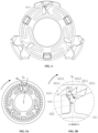
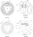
- the clockwise direction of the lacing device using the novel stop piece-retractable swing arm ring structure is the direction of tensioning the lace, such that the arrangement of the stop piece 44 can prevent the rotatable cover and the spool from rotating in the counterclockwise direction under the action of the external force in the loosening direction, thereby preventing the lace from being accidentally disengaged in the tensioning state.
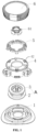
- the housing 4 is also provided with a ring of buckle protrusions 41, an inner wall of a cavity of the corresponding rotatable cover 6 has at least one buckle position (hidden in the figure), and the rotatable cover 6 is pressed and buckled on the outer periphery of the housing to form a whole locking structure of the lacing device.
- the rotatable cover 6 When the lacing device is in use, the rotatable cover 6 is pressed down hard, and a "click" sound can be heard, such that the engaging teeth on the rotatable cover 6 is meshed with the engaging teeth on the spool 3, and the rotatable cover 6 can rotate to drive the spool 3 to rotate together at this time.
- the rotatable cover 6 is rotated in the tensioning direction, and a crisp "click” sound can be heard.
- the tooth portion 5211 of the swing arm head is engaged with the gap on the rotatable cover, and the engaging teeth on the rotatable cover and the end face of the spool are meshed.
- a first side wall BL1 of the gap 6512 extrudes the tooth portion 5212 of the swing arm, forcing the swing arm head and the swing arm beam 522 to be deviated to give way in the direction of an extrusion force F1.
- the extrusion force F1 is perpendicular to the side wall BL1, and is also parallel to the slope surface 4411 of the wedge-shaped head 441 of the stop piece. Therefore, under the action of the extrusion force F1, the moving tendency of the swing arm head is parallel or nearly parallel to the slope surface 4411 of the wedge-shaped head of the stop piece.
- the wedge-shaped head of the stop piece will not hinder the displacement of the swing arm head in this direction, and at the same time, part of the extrusion force applied by the side wall BL1 of the gap 6512 to the swing arm tooth 5212 is transmitted to the elastic base 511 connected therewith along the swing arm beam 522 and forces the elastic base 511 to elastically deform, so as to further drive the swing arm beam to move radially inward.
- the first side wall TS1 of the tooth portion 5212 of the swing arm can slide in the direction of A1 to A2 along the first side wall BL1 of the gap 6512.
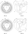
- the rotating force is continuously applied, the tooth portion 5212 of the swing arm slides to a first end point DD1 of the gap along the first side wall BL1 of the gap, and at this time, the swing arm is inclined to give away to the maximum extent and reaches a critical position A3, which is unstable.
- the tooth portion 5212 of the swing arm is quickly engaged with the next gap 6513, and reaches a position A4 for re-engagement.
- the gap is advanced one step in the clockwise direction. The previous tensioning action is repeated to realize the rotation of the rotatable cover and the spool round and round.
- a second side wall BL2 of the gap exerts bias pressure on the swing arm tooth when the rotatable cover is rotated in the loosening direction (counterclockwise direction).
- the biasing force F2 includes a counterclockwise circumferential component force F21 and an upward radial component force F22.
- the swing arm head Under the action of the circumferential component force F21, the swing arm head is inclined in the counterclockwise direction, such that the first side surface NS1 of the neck portion 5213 of the swing arm abuts against the slope surface 4411 of the wedge-shaped head of the stop piece, the swing arm beam partially abuts against the base portion of the stop piece, the slope surface 4411 applies an oblique upward extrusion force P1 to the neck portion 5212, and the base portion of the stop piece applies a transverse extrusion force P2 to the swing arm beam.
- the extrusion force P1 is in a direction basically the same as that of the first side wall of the swing arm tooth, and has an upward radial component force P12 and a circumferential component force P11.
- the circumferential component force P11 can partially deviate the circumferential component force of the biasing force F2.
- a combined force of the extrusion force P1 and the biasing force F2 makes the swing arm tooth push up against the gap of the rotatable cover, that is, the extrusion force applied by the stop piece to the swing arm forms a first self-locking force for engagement of the swing arm tooth with the gap of the rotatable cover.
- the extrusion force P2 applied by the base portion of the stop piece to the swing arm beam is basically a circumferential force, which can restrict the swing arm from swinging to the side in the counterclockwise direction.
- the radial direction of the radial component force of the biasing force F2 received by each tooth portion corresponds to a radial direction R1 or R2 where a second end point DD2 of each tooth portion is located separately.
- the radial direction of the radial component force of the extrusion force P1 applied by the slope surface 4411 to the neck portion 5212 refers to the R 0 direction in FIG. 5B .
- the same structure is marked with the same reference numeral. If there is no corresponding reference numeral in a single figure, reference may be made to the figure with the corresponding structure reference numeral.
- the upward radial component force also makes the swing arm tooth push against the side wall of the gap to form a second self-locking force for engagement of the swing arm tooth with the gap of the rotatable cover.
- a single stop piece can achieve an anti-reverse effect superior than that of the structure with two stop pieces corresponding to one swing arm.
- the design is ingenious and the anti-reverse effect is remarkable.
- the structures of the gap and the elastic base are exactly the same, and thus are marked with the same reference numerals.
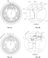
- the difference lies in the structural design of the swing arm and the stop piece. More specifically, as shown in FIG. 10B , in this comparative example, the swing arm head only includes a tooth portion without a neck portion, and includes only one tooth portion 5212'.
- the structure of a single tooth portion is the same as that of Embodiment 1, and the stop piece 44' is not provided with a wedge-shaped head. Only the base portion is arranged adjacent to the swing arm beam 522, and the structure of the swing arm beam 522 is the same as that of Embodiment 1.
- the second side wall BL2 of the gap 6512 applies an extrusion force to the second tooth wall TS2' of the swing arm tooth 5212'.
- this component force is very small, most of which are circumferential component forces.
- the swing arm abuts against the stop piece.
- a contact point of the stop piece and the swing arm constitutes a fulcrum P of the lever, which further increases the external force in the loosening direction.
- the first side wall BL1 of the gap will also apply a certain extrusion force to the swing arm tooth, and the extrusion force has a radially inward component force.
- the radially inward component force of the extrusion force is transmitted to the elastic base 511. Due to the strong deformation ability of the elastic base, elastic deformation will occur even when the radially inward force is small.
- the contact between the swing arm tooth and the second side wall of the gap gradually changes into a point contact, and the extrusion force applied by the gap of the rotatable cover to the swing arm tooth is equivalent to the external pressure on one end of the lever.
- the lever principle under the action of the force and the characteristics of easy deformation of the elastic base, the tail of the swing arm will tilt up. With the increase of the tilt degree of the tail, the hindering effect of the stop piece on the swing arm gradually decreases.
- the swing arm tooth is gradually disengaged from the gap until a critical position shown in FIG. 11B , and only the apex of the tooth portion 5212' is in contact with the first end point DD1 of the gap 6512.
- the position of the contact point P between the stop piece and the swing arm (equivalent to the fulcrum of a lever) on the swing arm may change continuously with the deviation displacement of the swing arm. Since the critical position is unstable, under the restoring elastic force of the swing arm and the elastic base 511, the tooth portion 5212' of the swing arm is quickly engaged with the next gap 6511 to achieve re-engagement. At this time, the gap is advanced one step in the counterclockwise direction. By continuously applying a large external force in the loosening direction, the rotatable cover and the spool can rotate in the counterclockwise direction round and round. The lacing device loses its anti-reverse function.
- the structural arrangement of the stop piece and the swing arm head cannot prevent the accidental loosening of the lace under a large external force in the loosening direction (an external force in the loosening direction exceeding a certain threshold), because when the external force in the loosening direction exceeds a certain threshold, the swing arm-stop piece-gap mechanism loses the anti-reverse function. Therefore, in special situations outdoors, the external force in the loosening direction is unexpectedly increased, and the lace is at risk of loosening. Therefore, although the characteristics of easy deformation of the elastic base 511 have an excellent effect on the improvement of the hand feeling when tensioning the lace, the corresponding risk of lace loosening also increases.
- the swing arm-stop piece-gap mechanism used by the comparative example only has the upward self-locking effect of the swing arm tooth and the gap and the anti-deflection effect of the base portion of the stop piece. This double effect can only be used for a small external force in the loosening direction. When the external force in the loosening direction exceeds a certain threshold, the anti-reverse effect is lost, so a lacing device using this mechanism can only have the effect of preventing the lacing from loosening for a small external force in the loosening direction.
Landscapes
- Chairs For Special Purposes, Such As Reclining Chairs (AREA)
- Prostheses (AREA)
- Orthopedics, Nursing, And Contraception (AREA)
- Transmission Devices (AREA)
- Footwear And Its Accessory, Manufacturing Method And Apparatuses (AREA)
- Containers And Plastic Fillers For Packaging (AREA)
Claims (16)
- Rücklaufsperrmechanismus für eine Schnürvorrichtung, umfassend:eine oder mehrere entlang eines Umfangs angeordnete Ausnehmungen (6511, 6512);eine elastische Schwingarmkomponente, umfassend einen elastischen Bauteil und einen oder mehrere entlang eines Umfangs angeordneten Schwingarmen (52), wobei der elastische Bauteil mit dem Schwingarm (52) verbunden ist; der Schwingarm (52) mindestens einen Schwingarmkopf (521) und einen Schwingarmträger (522), der sich radial nach außen entlang des Umfangs erstreckt, umfasst, wobei der Schwingarm (52) eine erste und eine zweite Seite aufweist, wobei sich die erste und die zweite Seite gegenüberliegen, wobei der Schwingarmkopf (521) so konfiguriert ist, dass er in die Ausnehmung (6511, 6512) eingreift, wenn sich der Schwingarm in seiner Ausgangsposition befindet, wobei der Schwingarmkopf (521) und/oder der Schwingarmträger (522) so konfiguriert ist/sind, dass sie von der Ausgangsposition in eine erste Richtung zur ersten Seite oder in eine entgegengesetzte zweite Richtung zur zweiten Seite des Schwingarms (52) abweichen; undein oder mehrere Anschlagstücke (44), wobei sich das Anschlagstück (44) auf der ersten Seite des Schwingarms (52) befindet, das Anschlagstück (44) und der Schwingarm (52) sich an einem gemeinsamen Teil befinden und getrennt angeordnet sind, dadurch gekennzeichnet, dass das Anschlagstück (44) einen keilförmigen Kopf (441) und einen Basisabschnitt (442) umfasst, wobei der keilförmige Kopf (441) des Anschlagstücks (44) entsprechend dem Schwingarmkopf (521) angeordnet ist und der Basisabschnitt (442) des Anschlagstücks (44) entsprechend dem Schwingarmträger (522) angeordnet ist;wobei, wenn die Ausnehmung (6511, 6512) oder der Schwingarm (52) einer äußeren Kraft in Festziehrichtung ausgesetzt ist, das Anschlagstück (44) und der elastische Bauteil dazu konfiguriert sind, eine Verschiebung des Schwingarms (52) relativ zur Ausnehmung (6511, 6512) zuzulassen, bis der Schwingarmkopf (521) von der Ausnehmung (6511, 6512) gelöst ist, um eine Drehung der Ausnehmung (6511, 6512) oder des Schwingarms (52) in Festziehrichtung zuzulassen; undwobei, wenn die Ausnehmung (6511, 6512) oder der Schwingarm (52) einer äußeren Kraft in Löserichtung ausgesetzt ist, die äußere Kraft in Löserichtung bewirkt, dass eine Seitenwand der Ausnehmung (6511, 6512) einen Vorspanndruck auf den Schwingarmkopf (521) ausübt, um den Schwingarmkopf (521) zur ersten Seite hin auszulenken, sodass zumindest ein Teil des Schwingarmkopfes (521) am keilförmigen Kopf (441) des Anschlagstücks (44) anliegt, wobei der keilförmige Kopf (441) des Anschlagstücks (44) verhindert, dass der Schwingarmkopf (521) weit zur ersten Seite hin auslenkt, der Basisabschnitt (442) des Anschlagstücks (44) verhindert, dass der Schwingarmträger (522) zur ersten Seite hin auslenkt, so dass der Schwingarmkopf (521) immer in Eingriff mit der Ausnehmung (6511, 6512) bleibt, um eine Drehung der Ausnehmung (6511, 6512) oder des Schwingarms (52) in Löserichtung zu verhindern.
- Rücklaufsperrmechanismus nach Anspruch 1, dadurch gekennzeichnet, dass die Ausnehmung (6511, 6512) ein offenes Ende mit zwei Endpunkten aufweist; die Ausnehmung (6511, 6512) ferner eine erste Seitenwand (BL1) und eine zweite Seitenwand (BL2) aufweist, wobei der Endpunkt des offenen Endes an der ersten Seitenwand (BL1) ein erster Endpunkt (DD1) und der Endpunkt des offenen Endes an der zweiten Seitenwand (BL2) ein zweiter Endpunkt (DD2) ist, wobei sich der erste Endpunkt (DD1) und der zweite Endpunkt (DD2) der Ausnehmung (6511, 6512) auf einem Umfang der Endpunkte der Ausnehmung (6511, 6512) befinden; wobei eine Gerade, entlang der die zweite Seitenwand (BL2) der Ausnehmung (6511, 6512) verläuft, und ein Radius durch den zweiten Endpunkt (DD2) des Umfangs der Endpunkte der Ausnehmung (6511, 6512) einen eingeschlossenen Winkel im Bereich von 0° bis 10° aufweisen.
- Rücklaufsperrmechanismus nach Anspruch 2, dadurch gekennzeichnet, dass der Schwingarmkopf (521) einen oder mehrere Zahnabschnitte (5211, 5212) und einen Halsabschnitt (5213) aufweist, wobei, wenn sich der Schwingarm (52) in der Ausgangsposition befindet, jeder der einen oder mehreren Zahnabschnitte (5211, 5212) des Schwingarmkopfs (521) mit der Ausnehmung (6511, 6512) in Eingriff steht.
- Rücklaufsperrmechanismus nach Anspruch 3, dadurch gekennzeichnet, dass der Halsabschnitt (5213) des Schwingarmkopfes (521) fächerringförmig oder trapezförmig ausgebildet ist.
- Neuartige Schnürvorrichtung, umfassend: eine drehbare Abdeckung (6), eine Spule (3), ein Gehäuse (4) und einen Rücklaufsperrmechanismus nach Anspruch 1, wobei die drehbare Abdeckung (6) drehbar am Gehäuse (4) angeordnet ist und die Spule (3) vom Gehäuse (4) getragen und relativ zum Gehäuse (4) drehbar ist;wobei die drehbare Abdeckung (6) mit einer oder mehreren Ausnehmungen (6511, 6512) versehen ist;wobei die Spule (3) so konfiguriert ist, dass sie beim Drehen in Festziehrichtung einen Schnürsenkel aufrollt und beim Drehen in Löserichtung den Schnürsenkel freigibt;wobei das Gehäuse (4) mit der elastischen Schwingarmkomponente versehen ist, und der Schwingarm (52) über den elastischen Bauteil mit dem Gehäuse (4) verbunden ist, wobei die erste Richtung die Löserichtung der Schnürvorrichtung ist;wobei das Gehäuse (4) ferner mit einem oder mehreren Anschlagstücken (44) versehen ist;wobei, wenn die drehbare Abdeckung (6) einer äußeren Kraft in Festziehrichtung ausgesetzt ist, das Anschlagstück (44) und der elastische Bauteil dazu konfiguriert sind, eine Verschiebung des Schwingarms (52) relativ zu der Ausnehmung (6511, 6512) der drehbaren Abdeckung (6) zuzulassen, bis der Schwingarmkopf (521) aus der Ausnehmung (6511, 6512) der drehbaren Abdeckung (6) gelöst ist, um eine Drehung der drehbaren Abdeckung (6) in der Festziehrichtung zuzulassen; undwobei, wenn die drehbare Abdeckung (6) einer äußeren Kraft in Löserichtung ausgesetzt ist, diese äußere Kraft in Löserichtung bewirkt, dass eine Seitenwand der Ausnehmung (6511, 6512) der drehbaren Abdeckung (6) einen Vorspanndruck auf den Schwingarmkopf (521) ausübt, um den Schwingarmkopf (521) zur ersten Seite hin auszulenken, sodass zumindest ein Teil des Schwingarmkopfes (521) am keilförmigen Kopf (441) des Anschlagstücks (44) anliegt, wobei der keilförmige Kopf (441) des Anschlagstücks (44) verhindert, dass der Schwingarmkopf (521) weit zur ersten Seite hin auslenkt, der Basisabschnitt (442) des Anschlagstücks (44) verhindert, dass der Schwingarmträger (522) zur ersten Seite hin auslenkt, so dass der Schwingarmkopf (521) immer in Eingriff mit der Ausnehmung (6511, 6512) der drehbaren Abdeckung (6) bleibt, um eine Drehung der drehbaren Abdeckung (6) in Löserichtung zu verhindern.
- Schnürvorrichtung nach Anspruch 5, dadurch gekennzeichnet, dass der Schwingarmkopf (521) einen oder mehrere Zahnabschnitte (5211, 5212) und einen Halsabschnitt (5213) aufweist, wobei, wenn die drehbare Abdeckung (6) einer äußeren Kraft in Löserichtung ausgesetzt ist, zumindest ein Teil des Halsabschnitts (5213) des Schwingarmkopfes (521) am keilförmigen Kopf (441) des Anschlagstücks (44) anliegt, und der Basisabschnitt (442) des Anschlagstücks (44) dazu konfiguriert ist, eine Abweichung des Schwingarmträgers (522) zu einer ersten Seite des Schwingarmträgers (522) zu verhindern.
- Schnürvorrichtung nach Anspruch 6, dadurch gekennzeichnet, dass der keilförmige Kopf (441) des Anschlagstücks (44) eine Schrägfläche (4411) aufweist, die an eine erste Seite des Halsabschnitts (5213) des Schwingarmkopfes (521) angrenzt, wobei eine Schräge-Spitze der Schrägfläche (4411) relativ zu einem Schräge-Fuß zu einer ersten Seite des keilförmigen Kopfes (441) geneigt ist und der Schräge-Fuß des keilförmigen Kopfes (441) an den Basisabschnitt (442) des Anschlagstücks (44) angrenzt.
- Schnürvorrichtung nach Anspruch 6, dadurch gekennzeichnet, dass, wenn sich der Schwingarm (52) in der Ausgangsposition befindet, jeder der einen oder mehreren Zahnabschnitte (5211, 5212) des Schwingarmkopfs (521) mit der Ausnehmung (6511, 6512) der drehbaren Abdeckung (6) in Eingriff steht.
- Schnürvorrichtung nach Anspruch 6, dadurch gekennzeichnet, dass der Schwingarmkopf (521) zwei Zahnabschnitte (5211, 5212) aufweist.
- Schnürvorrichtung nach Anspruch 6, dadurch gekennzeichnet, dass der Halsabschnitt (5213) des Schwingarmkopfes (521) eine erste Seitenfläche (NS1) aufweist, wobei die erste Seitenfläche (NS1) des Halsabschnitts (5213) und eine erste Zahnwand (TS1) der Zahnabschnitte (5211, 5212) einen eingeschlossenen Winkel im Bereich von 60° bis 120° aufweisen.
- Schnürvorrichtung nach Anspruch 6, dadurch gekennzeichnet, dass der Halsabschnitt (5213) des Schwingarmkopfes (521) eine erste Seitenfläche (NS1) aufweist, wobei die erste Seitenfläche (NS1) parallel zu einer Schrägfläche (4411) des keilförmigen Kopfes (441) des Anschlagstücks (44) angeordnet ist.
- Schnürvorrichtung nach Anspruch 10, dadurch gekennzeichnet, dass ein erster Zahnabschnitt (5212) des einen oder der mehreren Zahnabschnitte an die erste Seitenfläche (NS1) des Halsabschnitts (5213) des Schwingarmkopfes (521) angrenzt und die erste Seitenfläche (NS1) des Halsabschnitts (5213) und eine erste Zahnwand (TS1) des ersten Zahnabschnitts (5212) senkrecht zueinander stehen.
- Schnürvorrichtung nach Anspruch 5, dadurch gekennzeichnet, dass das Anschlagstück (44) und der Schwingarm (52) getrennt und in einer eins-zu-eins Entsprechung angeordnet sind.
- Schnürvorrichtung nach Anspruch 5, dadurch gekennzeichnet, dass der elastische Bauteil eine elastische Basis (511) oder eine aus einer elastischen Basis (511) bestehende elastische Ringbasis (51) ist.
- Schnürvorrichtung nach Anspruch 14, dadurch gekennzeichnet, dass die elastische Schwingarmkomponente ein einziehbarer Schwingarmring (5) ist, der die elastische Ringbasis (51) und einen oder mehrere mit der elastischen Ringbasis (51) verbundene Schwingarme (52) umfasst, wobei sich der Schwingarmträger (522) radial vom Umfang der elastischen Ringbasis (51) nach außen erstreckt, und der Schwingarm (52) über die elastische Ringbasis (51) mit dem Gehäuse (4) verbunden ist.
- Neuartige Schnürvorrichtung, umfassend: eine drehbare Abdeckung (6), eine Spule (3), ein Gehäuse (4) und einen Rücklaufsperrmechanismus nach Anspruch 1, wobei die drehbare Abdeckung (6) drehbar am Gehäuse (4) angeordnet ist und die Spule (3) vom Gehäuse (4) getragen und relativ zum Gehäuse (4) drehbar ist,wobei das Gehäuse (4) mit einer oder mehreren Ausnehmungen (6511, 6512) versehen ist;wobei die Spule (3) so konfiguriert ist, dass sie beim Drehen in Festziehrichtung einen Schnürsenkel aufrollt und beim Drehen in Löserichtung den Schnürsenkel freigibt;wobei die drehbare Abdeckung (6) mit der elastischen Schwingarmkomponente versehen ist, und der Schwingarm (52) über den elastischen Bauteil mit der drehbaren Abdeckung (6) verbunden ist, wobei die erste Richtung die Festziehrichtung der Schnürvorrichtung ist;wobei die drehbare Abdeckung (6) ferner mit einem oder mehreren Anschlagstücken (44) versehen ist;wobei, wenn die drehbare Abdeckung (6) einer äußeren Kraft in Festziehrichtung ausgesetzt ist, das Anschlagstück (44) und der elastische Bauteil dazu konfiguriert sind, eine Verschiebung des Schwingarms (52) relativ zu der Ausnehmung (6511, 6512) des Gehäuses (4) zuzulassen, bis der Schwingarmkopf (521) aus der Ausnehmung (6511, 6512) des Gehäuses (4) gelöst ist, um eine Drehung der drehbaren Abdeckung (6) in der Festziehrichtung zuzulassen; undwobei, wenn die drehbare Abdeckung (6) einer äußeren Kraft in Löserichtung ausgesetzt ist, diese äußere Kraft in Löserichtung bewirkt, dass eine Seitenwand der Ausnehmung (6511, 6512) des Gehäuses (4) einen Vorspanndruck auf den Schwingarmkopf (521) ausübt, um den Schwingarmkopf (521) zur ersten Seite hin auszulenken, sodass zumindest ein Teil des Schwingarmkopfes (521) am keilförmigen Kopf (441) des Anschlagstücks (44) anliegt, wobei der keilförmige Kopf (441) des Anschlagstücks (44) verhindert, dass der Schwingarmkopf (521) weit zur ersten Seite hin auslenkt, der Basisabschnitt (442) des Anschlagstücks (44) verhindert, dass der Schwingarmträger (522) zur ersten Seite hin auslenkt, so dass der Schwingarmkopf (521) immer in Eingriff mit der Ausnehmung (6511, 6512) des Gehäuses (4) bleibt, um eine Drehung der drehbaren Abdeckung (6) in Löserichtung zu verhindern.
Applications Claiming Priority (2)
| Application Number | Priority Date | Filing Date | Title |
|---|---|---|---|
| CN202210068932.4A CN116509108A (zh) | 2022-01-21 | 2022-01-21 | 一种新型的系带装置及其止逆机构 |
| PCT/CN2022/086784 WO2023137886A1 (zh) | 2022-01-21 | 2022-04-14 | 一种新型的系带装置及其止逆机构 |
Publications (4)
| Publication Number | Publication Date |
|---|---|
| EP4241609A1 EP4241609A1 (de) | 2023-09-13 |
| EP4241609A4 EP4241609A4 (de) | 2024-01-10 |
| EP4241609C0 EP4241609C0 (de) | 2025-05-14 |
| EP4241609B1 true EP4241609B1 (de) | 2025-05-14 |
Family
ID=85384407
Family Applications (1)
| Application Number | Title | Priority Date | Filing Date |
|---|---|---|---|
| EP22823314.4A Active EP4241609B1 (de) | 2022-01-21 | 2022-04-14 | Neuartige schnürvorrichtung und anti-reverse-mechanismus dafür |
Country Status (7)
| Country | Link |
|---|---|
| US (1) | US12116238B2 (de) |
| EP (1) | EP4241609B1 (de) |
| JP (1) | JP7538989B2 (de) |
| KR (1) | KR102869366B1 (de) |
| CN (1) | CN116509108A (de) |
| AU (1) | AU2022291677B2 (de) |
| WO (1) | WO2023137886A1 (de) |
Families Citing this family (7)
| Publication number | Priority date | Publication date | Assignee | Title |
|---|---|---|---|---|
| US12440001B2 (en) * | 2022-02-17 | 2025-10-14 | Pride Manufacturing Company, Llc | Micro-adjustable rotary closure |
| TW202406824A (zh) * | 2022-08-01 | 2024-02-16 | 蔡志信 | 緊固裝置 |
| JP1763586S (ja) * | 2022-11-21 | 2024-02-15 | 締め付けボタン | |
| US12402695B2 (en) * | 2022-12-15 | 2025-09-02 | Shenzhen Icomwell Intelligent Medical Technology Co., Ltd. | Spool, tightening device with spool, and coupling method of spool and lace |
| KR20250130681A (ko) * | 2023-01-12 | 2025-09-02 | 보아 테크놀러지, 인크. | 릴 기반 폐쇄 디바이스 |
| CN117413997B (zh) * | 2023-10-25 | 2024-10-22 | 石狮市森科智能科技有限公司 | 一种系带装置 |
| WO2025255355A1 (en) * | 2024-06-07 | 2025-12-11 | Ossur Iceland Ehf | Tensioning device |
Family Cites Families (64)
| Publication number | Priority date | Publication date | Assignee | Title |
|---|---|---|---|---|
| IT1188254B (it) * | 1986-01-13 | 1988-01-07 | Nordica Spa | Dispositivo di azionamento con funzione multipla particolarmente per scarponi da sci |
| US6257382B1 (en) * | 1999-08-20 | 2001-07-10 | Sheng-Hsin Liao | Cable winding apparatus |
| US6375109B1 (en) * | 2000-02-29 | 2002-04-23 | Sheng-Hsin Liao | Wire winding box for short distance use |
| US7367522B2 (en) * | 2005-10-14 | 2008-05-06 | Chin Chu Chen | String fastening device |
| WO2010059989A2 (en) * | 2008-11-21 | 2010-05-27 | Boa Technology, Inc. | Reel based lacing system |
| US10070695B2 (en) * | 2010-04-30 | 2018-09-11 | Boa Technology Inc. | Tightening mechanisms and applications including the same |
| DE112011106171B3 (de) * | 2010-04-30 | 2022-10-27 | Boa Technology, Inc. | Aufrollerbasiertes Schnürsystem |
| KR101099458B1 (ko) * | 2011-07-25 | 2011-12-27 | 주식회사 신경 | 신발끈 조임장치 |
| US9101181B2 (en) * | 2011-10-13 | 2015-08-11 | Boa Technology Inc. | Reel-based lacing system |
| KR101249420B1 (ko) * | 2012-12-17 | 2013-04-03 | 주식회사 신경 | 와이어 조임장치 |
| US10251451B2 (en) * | 2013-03-05 | 2019-04-09 | Boa Technology Inc. | Closure devices including incremental release mechanisms and methods therefor |
| US10076160B2 (en) * | 2013-06-05 | 2018-09-18 | Boa Technology Inc. | Integrated closure device components and methods |
| JP6087219B2 (ja) | 2013-06-18 | 2017-03-01 | 株式会社ジャパーナ | 靴紐巻取装置 |
| EP3019043B1 (de) * | 2013-07-10 | 2019-09-18 | Boa Technology Inc. | Verschlussvorrichtungen mit inkrementellen lösemechanismen und verfahren dafür |
| CN203492894U (zh) | 2013-09-11 | 2014-03-26 | 陈金柱 | 带体收放装置 |
| KR102350912B1 (ko) * | 2013-09-13 | 2022-01-13 | 보아 테크놀러지, 인크. | 릴 기반 폐쇄 장치 및 그에 따른 방법 |
| FR3023455B1 (fr) * | 2014-07-08 | 2016-08-26 | Mavic Sas | Dispositif d'enroulement et de blocage a cliquet d'un lacet de serrage |
| JP6406919B2 (ja) | 2014-08-11 | 2018-10-17 | 株式会社ジャパーナ | 靴紐巻取装置の取付構造 |
| WO2016033792A1 (zh) * | 2014-09-05 | 2016-03-10 | 陈金柱 | 带体收放装置及其收放方法 |
| KR101874925B1 (ko) * | 2015-08-21 | 2018-07-05 | 김석환 | 스트링 권취장치 및 이를 이용한 신발과 옷 |
| KR101607690B1 (ko) * | 2015-06-05 | 2016-03-30 | 구연욱 | 와이어 릴 |
| CN106919220B (zh) * | 2015-12-25 | 2018-06-05 | 陈金柱 | 紧固装置 |
| CN207604572U (zh) * | 2016-02-11 | 2018-07-13 | 河荣浩 | 夹线装置 |
| US11806264B2 (en) * | 2016-05-03 | 2023-11-07 | Icarus Medical, LLC | Adjustable tensioning device |
| FR3051334B1 (fr) * | 2016-05-18 | 2018-06-15 | Mavic Sas | Dispositif d'enroulement et de blocage pour un lacet de serrage |
| JP6882827B2 (ja) * | 2016-08-10 | 2021-06-02 | 株式会社アルペン | 巻取装置 |
| EP3539405B1 (de) * | 2016-11-11 | 2023-01-18 | Chin-Chu Chen | Befestigungsvorrichtung und verfahren zum zusammensetzen derselben |
| CN206187398U (zh) * | 2016-11-11 | 2017-05-24 | 陈金柱 | 紧固装置 |
| US11607014B2 (en) * | 2016-11-11 | 2023-03-21 | Chin-Chu Chen | Fastening device and lace assembling method |
| KR101723579B1 (ko) * | 2016-11-29 | 2017-04-06 | 주식회사 신경 | 와이어 조임장치 |
| KR101837194B1 (ko) * | 2016-12-30 | 2018-03-13 | 소윤서 | 줄 길이 조절장치 |
| CN107055221B (zh) * | 2017-01-21 | 2018-07-24 | 鸿康医疗器材用品(深圳)有限公司 | 绳带松紧调节固定器 |
| KR101804801B1 (ko) * | 2017-03-13 | 2017-12-05 | 하민우 | 와이어 조임장치 |
| KR101833680B1 (ko) * | 2017-08-04 | 2018-02-28 | 김정곤 | 신발끈의 조임장치 |
| CN208993976U (zh) | 2018-08-14 | 2019-06-18 | 深圳市爱康伟达智能医疗科技有限公司 | 一种系带装置及用于该装置的齿 |
| US10856620B2 (en) * | 2017-12-29 | 2020-12-08 | Shenzhen City Aikang Weida Intelligent Medical Technology Co., Ltd. | Lacing device based on rotor and stator, lacing system containing same and use method thereof |
| US10558052B2 (en) * | 2018-03-23 | 2020-02-11 | Htc Corporation | Adjusting mechanism and head mounted display |
| KR102314745B1 (ko) * | 2018-09-07 | 2021-10-19 | 타이렌 주식회사 | 끈 조절장치 |
| US10633218B2 (en) * | 2018-09-13 | 2020-04-28 | Yu-Chien WANG | Reel device |
| CN111003616A (zh) * | 2018-10-08 | 2020-04-14 | 王祐谦 | 卷线器 |
| US11033003B1 (en) * | 2018-10-21 | 2021-06-15 | George Wayne Burkhardt | Retractable leash device and method therefor |
| US11633018B2 (en) * | 2018-10-29 | 2023-04-25 | Pride Manufacturing Company, Llc | Latching system for a rotary closure |
| CN111115388B (zh) * | 2018-10-30 | 2021-11-19 | 陈金柱 | 紧固装置 |
| CN111115389B (zh) * | 2018-10-30 | 2022-04-05 | 陈金柱 | 紧固装置 |
| US11064767B2 (en) * | 2018-10-30 | 2021-07-20 | Chin-Chu Chen | Fastening device |
| US12207706B2 (en) * | 2018-10-30 | 2025-01-28 | Chin-Chu Chen | Fastening device |
| CN109386574B (zh) * | 2018-11-20 | 2024-06-28 | 深圳市菲特奥科技有限公司 | 一种绳带调节装置及具有该绳带调节装置的用品 |
| KR102189249B1 (ko) * | 2019-04-10 | 2020-12-09 | 하민우 | 와이어 조임장치 |
| WO2020223631A1 (en) * | 2019-05-01 | 2020-11-05 | Boa Technology Inc. | Reel based closure system |
| JP2022530682A (ja) | 2019-05-03 | 2022-06-30 | プライド マニュファクチャリング カンパニー リミテッド ライアビリティ カンパニー | 回転式クロージャ用システム及び方法 |
| CN110921437B (zh) * | 2019-12-18 | 2024-10-01 | 深圳市菲特奥科技有限公司 | 一种收绳装置及具有绳带的用品 |
| EP4103009A4 (de) * | 2020-02-14 | 2024-03-13 | Shift Holding, LLC | Schalttrommel und zugehörige verfahren |
| CN112089154B (zh) * | 2020-09-28 | 2025-07-29 | 李付德 | 一种旋钮装置 |
| CN215423119U (zh) * | 2021-01-25 | 2022-01-07 | 深圳市爱康伟达智能医疗科技有限公司 | 一种系带装置及其摆臂-凸块结构 |
| WO2022182990A1 (en) * | 2021-02-25 | 2022-09-01 | Pride Manufacturing Company, Llc | Systems and methods for an improved rotary closure |
| CN215501560U (zh) * | 2021-07-12 | 2022-01-14 | 苏州星诺奇科技股份有限公司 | 一种系带装置 |
| CN216272500U (zh) | 2021-08-17 | 2022-04-12 | 深圳市爱康伟达智能医疗科技有限公司 | 一种卷线筒及基于其的系紧机构 |
| US20230200356A1 (en) * | 2021-12-29 | 2023-06-29 | Dongguan Jiasheng Enterprise Co., Ltd | Retractable pet leash |
| EP4456756A1 (de) * | 2021-12-30 | 2024-11-06 | Boa Technology, Inc. | Verschlusssystem auf rollenbasis |
| US12336597B2 (en) * | 2022-08-01 | 2025-06-24 | Chin-Chu Chen | Fastening device |
| TW202406824A (zh) * | 2022-08-01 | 2024-02-16 | 蔡志信 | 緊固裝置 |
| CN115413863A (zh) * | 2022-09-01 | 2022-12-02 | 泉州振科技术服务有限公司 | 一种转动式绳物收放装置、鞋及物品 |
| WO2024259562A1 (zh) * | 2023-06-19 | 2024-12-26 | 深圳市益思特科技有限公司 | 绳线收放装置、鞋子、手套、医疗护具及收纳装置 |
| CN220442052U (zh) * | 2023-07-29 | 2024-02-06 | 江西思创通智能科技有限公司 | 一种新型的系带系统 |
-
2022
- 2022-01-21 CN CN202210068932.4A patent/CN116509108A/zh active Pending
- 2022-04-14 EP EP22823314.4A patent/EP4241609B1/de active Active
- 2022-04-14 WO PCT/CN2022/086784 patent/WO2023137886A1/zh not_active Ceased
- 2022-09-30 US US17/956,895 patent/US12116238B2/en active Active
- 2022-12-29 KR KR1020220188389A patent/KR102869366B1/ko active Active
- 2022-12-29 AU AU2022291677A patent/AU2022291677B2/en active Active
-
2023
- 2023-01-13 JP JP2023003829A patent/JP7538989B2/ja active Active
Also Published As
| Publication number | Publication date |
|---|---|
| EP4241609C0 (de) | 2025-05-14 |
| JP2023107215A (ja) | 2023-08-02 |
| AU2022291677B2 (en) | 2024-08-08 |
| EP4241609A4 (de) | 2024-01-10 |
| EP4241609A1 (de) | 2023-09-13 |
| KR102869366B1 (ko) | 2025-10-14 |
| KR20230113151A (ko) | 2023-07-28 |
| US12116238B2 (en) | 2024-10-15 |
| AU2022291677A1 (en) | 2023-08-10 |
| US20230234809A1 (en) | 2023-07-27 |
| WO2023137886A1 (zh) | 2023-07-27 |
| JP7538989B2 (ja) | 2024-08-23 |
| CN116509108A (zh) | 2023-08-01 |
Similar Documents
| Publication | Publication Date | Title |
|---|---|---|
| EP4241609B1 (de) | Neuartige schnürvorrichtung und anti-reverse-mechanismus dafür | |
| US20240417213A1 (en) | Lacing device and anti-reverse mechanism thereof | |
| US7578334B2 (en) | Control system for architectural coverings with reversible drive and single operating element | |
| CN216723374U (zh) | 一种新型的系带装置及其止逆机构 | |
| JP2023553009A (ja) | リール式クロージャー装置 | |
| KR20250030029A (ko) | 릴 기반 폐쇄 시스템 | |
| US5745963A (en) | Adjustable fastening device for sports footwear | |
| CN216256587U (zh) | 一种基于销杆弹性组件的止逆机构及系紧装置 | |
| US20240375910A1 (en) | Reel based closure device | |
| JPH01284685A (ja) | ベネチアン・ブラインド用クラッチ集合体 | |
| KR20240017766A (ko) | 체결 디바이스 | |
| US20170369267A1 (en) | Horizontal-pull coating film transferring tool | |
| CN215837385U (zh) | 一种基于摆臂结构的系带装置及其摆臂-凹槽-挡块结构 | |
| US20120266418A1 (en) | Buckle for swimming/diving goggles | |
| WO2024199546A1 (zh) | 一种系带锁扣结构以及系带装置 | |
| CN114788600A (zh) | 一种基于摆臂结构的系带装置 | |
| US20070017050A1 (en) | Roller-type paintbrush | |
| JPS5951803B2 (ja) | 合成樹脂製連続フアスナ−エレメント列を有するスライドフアスナ− | |
| US682684A (en) | Snap-hook. | |
| CN120020081A (zh) | 一种系紧机构及其止回组件 | |
| CN215423119U (zh) | 一种系带装置及其摆臂-凸块结构 | |
| CN115702732A (zh) | 一种基于销杆弹性组件的止逆机构及系紧装置 | |
| JP6687307B2 (ja) | 巻取装置 | |
| CN222466213U (zh) | 皮带扣及腰带 | |
| US4985798A (en) | Magnetic tape cassette having improved dust proofing |
Legal Events
| Date | Code | Title | Description |
|---|---|---|---|
| STAA | Information on the status of an ep patent application or granted ep patent |
Free format text: STATUS: UNKNOWN |
|
| STAA | Information on the status of an ep patent application or granted ep patent |
Free format text: STATUS: THE INTERNATIONAL PUBLICATION HAS BEEN MADE |
|
| PUAI | Public reference made under article 153(3) epc to a published international application that has entered the european phase |
Free format text: ORIGINAL CODE: 0009012 |
|
| STAA | Information on the status of an ep patent application or granted ep patent |
Free format text: STATUS: REQUEST FOR EXAMINATION WAS MADE |
|
| 17P | Request for examination filed |
Effective date: 20221223 |
|
| AK | Designated contracting states |
Kind code of ref document: A1 Designated state(s): AL AT BE BG CH CY CZ DE DK EE ES FI FR GB GR HR HU IE IS IT LI LT LU LV MC MK MT NL NO PL PT RO RS SE SI SK SM TR |
|
| A4 | Supplementary search report drawn up and despatched |
Effective date: 20231213 |
|
| RIC1 | Information provided on ipc code assigned before grant |
Ipc: A43C 11/16 20060101AFI20231207BHEP |
|
| STAA | Information on the status of an ep patent application or granted ep patent |
Free format text: STATUS: EXAMINATION IS IN PROGRESS |
|
| 17Q | First examination report despatched |
Effective date: 20240805 |
|
| GRAP | Despatch of communication of intention to grant a patent |
Free format text: ORIGINAL CODE: EPIDOSNIGR1 |
|
| STAA | Information on the status of an ep patent application or granted ep patent |
Free format text: STATUS: GRANT OF PATENT IS INTENDED |
|
| DAV | Request for validation of the european patent (deleted) | ||
| DAX | Request for extension of the european patent (deleted) | ||
| INTG | Intention to grant announced |
Effective date: 20250212 |
|
| GRAS | Grant fee paid |
Free format text: ORIGINAL CODE: EPIDOSNIGR3 |
|
| GRAA | (expected) grant |
Free format text: ORIGINAL CODE: 0009210 |
|
| STAA | Information on the status of an ep patent application or granted ep patent |
Free format text: STATUS: THE PATENT HAS BEEN GRANTED |
|
| RAP3 | Party data changed (applicant data changed or rights of an application transferred) |
Owner name: SHENZHEN ICOMWELL INTELLIGENT MEDICALTECHNOLOGY CO., LTD. |
|
| AK | Designated contracting states |
Kind code of ref document: B1 Designated state(s): AL AT BE BG CH CY CZ DE DK EE ES FI FR GB GR HR HU IE IS IT LI LT LU LV MC MK MT NL NO PL PT RO RS SE SI SK SM TR |
|
| REG | Reference to a national code |
Ref country code: GB Ref legal event code: FG4D |
|
| REG | Reference to a national code |
Ref country code: CH Ref legal event code: EP |
|
| REG | Reference to a national code |
Ref country code: IE Ref legal event code: FG4D |
|
| U01 | Request for unitary effect filed |
Effective date: 20250516 |
|
| U07 | Unitary effect registered |
Designated state(s): AT BE BG DE DK EE FI FR IT LT LU LV MT NL PT RO SE SI Effective date: 20250522 |
|
| PG25 | Lapsed in a contracting state [announced via postgrant information from national office to epo] |
Ref country code: ES Free format text: LAPSE BECAUSE OF FAILURE TO SUBMIT A TRANSLATION OF THE DESCRIPTION OR TO PAY THE FEE WITHIN THE PRESCRIBED TIME-LIMIT Effective date: 20250514 |
|
| PG25 | Lapsed in a contracting state [announced via postgrant information from national office to epo] |
Ref country code: NO Free format text: LAPSE BECAUSE OF FAILURE TO SUBMIT A TRANSLATION OF THE DESCRIPTION OR TO PAY THE FEE WITHIN THE PRESCRIBED TIME-LIMIT Effective date: 20250814 Ref country code: GR Free format text: LAPSE BECAUSE OF FAILURE TO SUBMIT A TRANSLATION OF THE DESCRIPTION OR TO PAY THE FEE WITHIN THE PRESCRIBED TIME-LIMIT Effective date: 20250815 |
|
| PG25 | Lapsed in a contracting state [announced via postgrant information from national office to epo] |
Ref country code: PL Free format text: LAPSE BECAUSE OF FAILURE TO SUBMIT A TRANSLATION OF THE DESCRIPTION OR TO PAY THE FEE WITHIN THE PRESCRIBED TIME-LIMIT Effective date: 20250514 |
|
| PG25 | Lapsed in a contracting state [announced via postgrant information from national office to epo] |
Ref country code: HR Free format text: LAPSE BECAUSE OF FAILURE TO SUBMIT A TRANSLATION OF THE DESCRIPTION OR TO PAY THE FEE WITHIN THE PRESCRIBED TIME-LIMIT Effective date: 20250514 |
|
| PG25 | Lapsed in a contracting state [announced via postgrant information from national office to epo] |
Ref country code: RS Free format text: LAPSE BECAUSE OF FAILURE TO SUBMIT A TRANSLATION OF THE DESCRIPTION OR TO PAY THE FEE WITHIN THE PRESCRIBED TIME-LIMIT Effective date: 20250814 |
|
| PG25 | Lapsed in a contracting state [announced via postgrant information from national office to epo] |
Ref country code: IS Free format text: LAPSE BECAUSE OF FAILURE TO SUBMIT A TRANSLATION OF THE DESCRIPTION OR TO PAY THE FEE WITHIN THE PRESCRIBED TIME-LIMIT Effective date: 20250914 |
|
| PG25 | Lapsed in a contracting state [announced via postgrant information from national office to epo] |
Ref country code: SM Free format text: LAPSE BECAUSE OF FAILURE TO SUBMIT A TRANSLATION OF THE DESCRIPTION OR TO PAY THE FEE WITHIN THE PRESCRIBED TIME-LIMIT Effective date: 20250514 |
|
| PG25 | Lapsed in a contracting state [announced via postgrant information from national office to epo] |
Ref country code: CZ Free format text: LAPSE BECAUSE OF FAILURE TO SUBMIT A TRANSLATION OF THE DESCRIPTION OR TO PAY THE FEE WITHIN THE PRESCRIBED TIME-LIMIT Effective date: 20250514 |
|
| PG25 | Lapsed in a contracting state [announced via postgrant information from national office to epo] |
Ref country code: SK Free format text: LAPSE BECAUSE OF FAILURE TO SUBMIT A TRANSLATION OF THE DESCRIPTION OR TO PAY THE FEE WITHIN THE PRESCRIBED TIME-LIMIT Effective date: 20250514 |