EP4241548A1 - Tête de distribution pour une machine de distribution agricole et machine de distribution et procédé de distribution de matériau - Google Patents
Tête de distribution pour une machine de distribution agricole et machine de distribution et procédé de distribution de matériau Download PDFInfo
- Publication number
- EP4241548A1 EP4241548A1 EP22401024.9A EP22401024A EP4241548A1 EP 4241548 A1 EP4241548 A1 EP 4241548A1 EP 22401024 A EP22401024 A EP 22401024A EP 4241548 A1 EP4241548 A1 EP 4241548A1
- Authority
- EP
- European Patent Office
- Prior art keywords
- return
- flow area
- area
- air
- discharge
- Prior art date
- Legal status (The legal status is an assumption and is not a legal conclusion. Google has not performed a legal analysis and makes no representation as to the accuracy of the status listed.)
- Pending
Links
- 239000000463 material Substances 0.000 title claims abstract description 99
- 238000009826 distribution Methods 0.000 title claims abstract description 22
- 238000000034 method Methods 0.000 title claims description 7
- 239000008187 granular material Substances 0.000 claims abstract description 39
- 238000003892 spreading Methods 0.000 claims abstract description 22
- 230000007480 spreading Effects 0.000 claims abstract description 22
- 238000003860 storage Methods 0.000 claims abstract description 17
- 238000000926 separation method Methods 0.000 claims description 39
- 238000012986 modification Methods 0.000 description 4
- 230000004048 modification Effects 0.000 description 4
- 238000000151 deposition Methods 0.000 description 3
- 230000000694 effects Effects 0.000 description 3
- 239000002689 soil Substances 0.000 description 3
- 239000011343 solid material Substances 0.000 description 2
- 238000004804 winding Methods 0.000 description 2
- 229910000831 Steel Inorganic materials 0.000 description 1
- XAGFODPZIPBFFR-UHFFFAOYSA-N aluminium Chemical compound [Al] XAGFODPZIPBFFR-UHFFFAOYSA-N 0.000 description 1
- 229910052782 aluminium Inorganic materials 0.000 description 1
- 238000007664 blowing Methods 0.000 description 1
- 230000008021 deposition Effects 0.000 description 1
- 230000001066 destructive effect Effects 0.000 description 1
- 239000003337 fertilizer Substances 0.000 description 1
- 238000004519 manufacturing process Methods 0.000 description 1
- 239000007769 metal material Substances 0.000 description 1
- JTJMJGYZQZDUJJ-UHFFFAOYSA-N phencyclidine Chemical class C1CCCCN1C1(C=2C=CC=CC=2)CCCCC1 JTJMJGYZQZDUJJ-UHFFFAOYSA-N 0.000 description 1
- 230000009467 reduction Effects 0.000 description 1
- 230000002441 reversible effect Effects 0.000 description 1
- 238000009331 sowing Methods 0.000 description 1
- 239000010959 steel Substances 0.000 description 1
- 238000003971 tillage Methods 0.000 description 1
- 230000007704 transition Effects 0.000 description 1
Images


Classifications
-
- A—HUMAN NECESSITIES
- A01—AGRICULTURE; FORESTRY; ANIMAL HUSBANDRY; HUNTING; TRAPPING; FISHING
- A01C—PLANTING; SOWING; FERTILISING
- A01C7/00—Sowing
- A01C7/08—Broadcast seeders; Seeders depositing seeds in rows
- A01C7/081—Seeders depositing seeds in rows using pneumatic means
- A01C7/084—Pneumatic distribution heads for seeders
Definitions
- the invention relates to a distributor head for an agricultural spreading machine according to the preamble of patent claim 1, an agricultural spreading machine according to the preamble of patent claim 13 and a method for distributing granular material according to the preamble of patent claim 14.
- Agricultural spreading machines such as seed drills
- a distribution device designed as a distribution head, in which granular material is introduced into a distribution area of the distribution head via a main delivery line, for example a riser pipe.
- the granular material introduced into the distributor head is then fed to several dispensing channels, via which the granular material is introduced into dispensing lines, each dispensing line leading to a storage device, for example a seed coulter.
- Corresponding distributor heads often also have return devices via which return flows of granular material from the discharge channels can be returned to the main delivery line.
- air discharge flow areas of the return devices allow air separated from a return flow to be introduced into a discharge channel or a discharge line so that the amount of air returned to the main delivery line does not lead to a flow stall in the main delivery line. Furthermore, this prevents the delivery of granular material from coming to a standstill as a result of the reduction in the volume flow, which would result in a blockage of the main delivery line.
- Distributor heads with return devices which include a material return flow area and an air discharge flow area, are for example from the publications WO 2017/055266 A1 and EP 3 372 065 B1 known.
- the object underlying the invention is to further improve the air separation in return devices of a distributor head.
- the object is achieved by a distributor head of the type mentioned at the outset, wherein in the distributor head according to the invention the material return flow region and the air discharge flow region of the respective return devices are pneumatically connected to one another along a separation section in such a way that air from a return flow flowing through the material return flow region can be separated into the air discharge flow region along the separation route .
- the material return flow area and the air removal flow area are therefore not pneumatically separated from one another by a channel or line wall, as was previously the case, but are pneumatically connected to one another along a separation path, so that air is separated from the return flow along the separation path.
- the deposition section preferably has a length of at least 10mm, more preferably a length of at least 20mm, particularly preferably a length of at least 30mm.
- the flow area available for air separation is significantly increased by providing a separation section.
- the separation period available for air separation is also significantly extended because air separation is possible while flowing through the entire separation section. Overall, the separation performance is significantly increased, so that the distributor head according to the invention can also be used in areas of application in which a pronounced air separation is required for the error-free operation of the distributor head.
- a material return path preferably runs along the material return flow areas of the return devices.
- the material return path preferably connects a discharge channel with the main delivery line, so that the returned material can be reintroduced into the main delivery line.
- Air discharge paths preferably run along the air discharge flow areas, via which the separated air can be fed to a discharge channel and/or a discharge line. Along the separation path, air can flow from the material return path into the air discharge path and be fed to a discharge channel and/or a discharge line via the air discharge path.
- the material return flow area and the air removal flow area preferably merge into one another, with the material return flow area and the air removal flow area being geometrically separated from one another via an edge. Flows in opposite directions preferably form in the material return flow area and the air removal flow area.
- the main delivery line can be an upright riser, for example a riser pipe.
- the distributor head according to the invention is advantageously further developed in that the material return flow area and the air discharge flow area of the respective return devices are separated from one another without any walls along the separation section.
- the material return flow area and the air removal flow area share a common flow space within the return devices. Because the material return flow area and the air removal flow area are wall-free separated from one another, an air-conducting connection between the material return flow area and the air removal flow area always remains present.
- the material return flow area and the air removal flow area can be pneumatically connected to one another along the separation path in such a way that the granular material does not pass from the material return flow area into the air removal flow area solely due to the flows that form.
- an air-permeable separating device for example a grid or a sieve, which cannot be passed by the granular material, can be arranged between the material return flow area and the air removal flow area.
- a distributor head is advantageous, in which the material return flow area rotates at least in sections, in particular spirally, around the air discharge flow area.
- the material return flow area forms a winding or outer helix that wraps around the air removal flow area.
- the material return flow area runs, for example, helically around the air removal flow area.
- the material flow within the material return flow area is therefore in the slipstream of the air flow in the air discharge flow area.
- the return devices therefore act like centrifugal separators or cyclones.
- the surrounding material return flow area causes the return flow to rotate so that the centrifugal force is used to separate air.
- the material return flow area can have a contour that changes over the course of the turn.
- the flow cross section of the air discharge flow area is larger than the flow cross section of the discharge channel and/or the flow cross section of the discharge line.
- the average flow cross section of the air discharge flow area is larger than the average flow cross section of the discharge channel and/or the average flow cross section of the discharge line. The flow velocity along the air discharge flow area is thus reduced. This reduces the risk of granular material from the material return flow area entering the air discharge flow area due to suction.
- the material return flow area and the air discharge flow area extend in sections along separate line sections.
- the material return flow area and the air discharge flow area are separated from one another in sections by a line wall.
- a line area which includes the inlet of the material return flow area and the outlet of the air discharge flow area, extend Material return flow area and the air discharge flow area along separate line sections.
- the distributor head according to the invention is further developed by a, in particular circumferential, return collection area, which is connected to the main delivery line and into which several or all of the material return flow areas open. Within the return collection area, several return flows are brought together before they are introduced into the main delivery line.
- the return collection area can be designed, for example, as a return funnel.
- the material return flow areas open obliquely into the return collection area, so that a vortex-shaped material flow preferably forms in the return collection area.
- the material return path therefore opens obliquely into the return collection area.
- the angle between the material return path and a horizontal axis is in a range between 10 and 80 degrees, preferably in a range between 20 and 60 degrees, in the transition region from the material return flow area to the return collection area.
- the spreading machine When driving on slopes, the spreading machine will tilt. Due to the slope, there is a risk that the return collection area will fill up on one side, namely on the side down the slope. This risk is minimized by the material return flow areas or the return flow paths opening obliquely into the return collection area in such a way that a circulating vortex-shaped material flow is formed within the material return flow area.
- a distributor head according to the invention with a deflection device is preferred, which can be moved into a feed-through position and a return position.
- a movable deflection body of the deflection device is preferably designed to block a passage from the discharge channel into the material return flow area in the passage position.
- the movable deflection body of the deflection device is designed to provide the passage in the return position from the discharge channel into the material return flow area.
- the deflection body can be a movable, in particular pivotable, deflection flap.
- the deflection bodies of the respective deflection devices can be connected to a drive, for example an electric drive. By controlling the drives, the forward position or the return position on the deflection device can be set.
- a distributor head according to the invention is also advantageous, in which the discharge channel and the air discharge flow area are permanently and/or permanently pneumatically connected to one another.
- the distributor head preferably does not have a locking device via which the permanent and/or permanent pneumatic connection between the dispensing channel and the air discharge flow area can be interrupted.
- the deflection body of the deflection device is designed to reduce the free flow cross section in the passage from the discharge channel into the air discharge flow area in the passage position.
- the deflection body preferably has a cover wing, by means of which the passage from the discharge channel into the air discharge flow area can be covered.
- the cover wing does not completely fill the passage from the discharge channel into the air discharge flow area, for example due to a recess, so that a permanent pneumatic connection between the discharge channel and the air discharge flow region is guaranteed.
- the granular material flows through the application channel and the application line to a depositing device, for example a seed coulter.
- a suction flow can occur from the discharge channel into the material return flow area and/or the air discharge flow area. Due to the suction, granular material can inadvertently flow into the air discharge flow area, thereby reducing the output.
- the cover wing counteracts this effect and therefore acts as a flow throttle.
- the deflection body can be a throttle rocker.
- the cover wing acts as a flow resistance so that the suction caused by the nozzle in the main delivery line does not cause sufficient suction to move granular material into the To suck in air discharge flow area. Granular material can pass through the recess or recesses in the cover wing.
- the return devices each comprise at least two shell parts, in particular half-shell parts, with the at least two shell parts each forming a return device.
- the return devices are preferably each divided into two half-shells.
- the return devices are preferably divided along their longitudinal direction.
- Both shell parts preferably comprise, at least in sections, a part of the air discharge flow area and/or a part of the material return flow area.
- the shell parts are preferably connected to one another in a reversible, non-destructive manner, for example by means of screws. Because the return devices are composed of non-destructively removable shell parts, the air discharge flow area and the material return flow area can be opened and possible blockages can be eliminated. In addition, production and assembly are simplified by dividing it into two shell parts.
- a discharge flow body is arranged in the air discharge flow area of the return devices, the discharge flow body preferably extending at least in sections along the separation path of the respective return devices in the air discharge flow area.
- the discharge flow body is preferably designed as an elongated body, for example as a rod or rod.
- the discharge flow body is preferably cylindrical with a round cross section.
- the discharge flow body can be made of a solid material or as a hollow body, for example as a tube.
- the discharge flow body can be made of a metallic material, for example steel or aluminum, or of a plastic.
- the discharge flow body can extend over the entire air discharge flow area of the return device along the separation section.
- the discharge flow body is preferably central in cross section, in particular in the center Air discharge flow area arranged.
- the discharge flow body extends parallel to a longitudinal axis of the return device.
- the discharge flow body can be connected to the return device at least in sections in its longitudinal extent inside the return device and fastened to the return device.
- the discharge flow body is attached in its upper and/or in its lower end region to the return device, in particular reversibly and non-destructively.
- the discharge flow body is preferably connected to the return device in a positive and/or non-positive manner, for example by means of a clamp connection or by means of screws.
- the discharge flow body can also be cohesively connected to the return device, for example glued or welded or at least partially enclosed by the material of the return device.
- the object on which the invention is based is further achieved by an agricultural spreading machine of the type mentioned at the outset, the distributor head of the agricultural spreading machine according to the invention being designed according to one of the embodiments described above.
- the advantages and modifications of the spreading machine according to the invention reference is made to the advantages and modifications of the distributor head according to the invention.
- the object on which the invention is based is further achieved by a method for distributing granular material of the type mentioned at the outset, the material return flow area and the air discharge flow area being within the scope of the method according to the invention respective return devices are pneumatically connected to one another along a separation section in such a way that air is separated from a return flow flowing through the material return flow area along the separation section into the air discharge flow area.
- the method is preferably carried out using a distributor head according to one of the embodiments described above.
- the Fig. 1 shows a machine assembly 200 with an agricultural towing vehicle 202 designed as a tractor and an agricultural spreading machine 100 designed as a seed drill.
- the agricultural spreading machine 100 is designed as a towed machine in the illustrated embodiment. In other embodiments, the agricultural spreading machine 100 can also be designed as a carried machine, so that the vehicle 202 functions as a carrier vehicle.
- the agricultural spreading machine 100 includes a storage container 102 for storing granular material, for example seeds and/or fertilizer.
- the granular material stored in the storage container 102 is fed to a distribution head 10 via a feed line 112.
- the distribution head 10 distributes the granular material to a plurality of discharge lines 110 (in the Fig. 1 the application lines 110 are hidden), the application lines 110 being connected to storage devices 104 of the agricultural application machine 100.
- the granular material is deposited onto an agricultural area via the storage devices 104.
- the storage devices 104 can be seed coulters, for example.
- the storage devices 104 are arranged on a machine frame 106 of the agricultural spreading machine 100. Soil cultivation tools 108 are also attached to the machine frame 106.
- the agricultural spreading machine 100 has several transverse rows of leading soil cultivation tools 108, which are arranged in front of the storage devices 104 in the direction of travel. Furthermore, the agricultural spreading machine 100 includes several transverse rows of trailing soil cultivation tools 109, which are arranged behind the storage devices 104 in the direction of travel.
- the distributor head 10 is equipped with deflection devices 38, via which the introduction of granular material into the discharge lines 110 leading to the storage devices 104 can be temporarily interrupted in order to The application of the granular material to the agricultural area is to be temporarily interrupted in a row-specific, area-specific or across the entire width of the agricultural spreading machine 100.
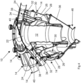
- the Fig. 2 to 4 show a distributor head 10 with a main delivery line 12.
- the main delivery line 12 connects to the feed line 112 of the agricultural spreading machine 100.
- the granular material is introduced into a distribution area 22 of the distributor head 10 via the main delivery line 12.
- Several discharge channels 24 extend from the distribution area 22, via which the granular material is introduced into discharge lines 110 leading to the storage devices 104.
- Deflection devices 38 are arranged on the discharge channels 24 of the distributor head 10, which can each be moved into a through-feed position and a return position.
- the deflection devices 38 each have a deflection body 40 designed as a movable deflection flap.
- the passage position the discharge channel 24 is released and a passage from the discharge channel via the line section 34 into a material return flow area 28 is blocked.
- the return position the deflection body 40 is pivoted in such a way that the passage from the discharge channel 24 via the line section 34 into the material return flow area 28 is released.
- the granular material is thus guided back into the main delivery line 12 via the line section 34 and the material return flow area 28 by means of a return flow.
- the material return flow area 28 is part of a return device 14 of the distributor head 10.
- the return device 14 further comprises an air discharge flow area 26. Via the air removal flow area 26, air separated from the return flow can be returned to the discharge channel 24 for blowing out via the discharge line 110. In this way, it is avoided that an excessive amount of air is returned to the main delivery line 12 when the deflection body 40 of the deflection device 38 blocks the discharge channel 24 in the return position of the deflection device 38.
- the material return flow area 28 spirals around the air discharge flow area 26.
- the material return flow area 28 forms a winding or outer helix that wraps around the air removal flow area 26.
- the material return flow area 28 and the air removal flow area 26 are separated from one another without walls along a spiral-shaped separation path 30.
- the flow spaces of the material return flow area 28 and the air discharge flow area 26 are pneumatically connected to one another along the separation section 30 and merge into one another along the separation section 30.
- the pneumatic connection between the material return flow area 28 and the air discharge flow area 26 along the separation section 30 allows air from the return flow flowing through the material return flow area 28 to be separated along the separation section 30 into the air removal flow area 26.
- air can therefore flow from the material return path, which extends along the material return flow region 28, into an air discharge path, which extends along the air discharge flow region 26, so that the separated air can be discharged via the discharge line 110.
- the material return flow area 28 and the air removal flow area 26 extend along separate line sections 32, 34. In this area, the material return flow area 28 and the air removal flow area 26 are separated from one another in sections by a line wall.
- the distributor head 10 further comprises a circumferential return collection area 36, which is connected to the main delivery line 12 and into which all material return flow areas 28 open.
- the return collection area 36 is a return funnel.
- the Material return flow areas 28 open obliquely into the return collection area 36, so that a vortex-shaped material flow is formed in the return collection area 36.
- the vortex-shaped material flow within the material return flow area 28 prevents the return collection area 36 from filling up on one side when driving on a slope and the resulting machine inclination.
- the delivery channels 24 are limited by walls 16.
- the air discharge flow areas 26 are limited by walls 18.
- the material return flow areas 28 are limited by walls 20.
- the average flow cross section of the air discharge flow area 26 is larger than the average flow cross section of the discharge channel 24 and larger than the average flow cross section of the discharge line 110. The flow velocity along the air discharge flow region 26 is thus reduced. This reduces the risk of granular material from the material return flow area 28 entering the air discharge flow area 26 due to a suction effect.
- the Fig. 5 shows a deflection device 38 of a return device 14.
- the deflection body 40 designed as a deflection flap has a cover wing 42, by means of which the passage from the discharge channel 24 into the air discharge flow area 26 is only partially filled due to recesses 44 in the cover wing 42. Due to the recesses 44, there is a permanent pneumatic connection between the discharge channel 24 and the air discharge flow area 26.
- a deposit device 104 for example a sowing coulter.
- the cover wing 42 of the deflection body 40 which has recesses 44, acts i.e. as a flow throttle.
- the deflection body 40 is designed as a throttle rocker.
- the cover wing 42 therefore serves as a flow resistance, so that the suction caused by the nozzle 46 in the main delivery line 12 does not produce a sufficient suction effect from the discharge channel 24 into the air discharge flow area 26 in order to suck in granular material into the air discharge flow area 26.
- the Fig. 6 shows that the cover wing 42 can also have a central circular recess instead of two semicircular recesses. In other embodiments, a different number of recesses 44 may also be present in the cover wing 42, wherein the recesses 44 may also have other shapes.
- the representation in the Fig. 6 shows that the wall 18 of the air discharge flow area 26 and the wall 20 of the material return flow area 28 merge into one another.
- the material return flow area 28 runs spirally around the air removal flow area 26, the material return flow area 28 and the air removal flow area 26 being pneumatically connected to one another along the separation section 30 and separated from one another without any walls.
- a separating device for example a grid or a sieve, can also be located along the separation section 30.
- the Fig. 7 shows a return device 14, which is divided in its longitudinal direction into two shell parts 50a, 50b designed as half-shells.
- the insides of the shell parts 50a, 50b can be seen.
- the shell parts 50a, 50b can be assembled and fastened together so that the shell parts 50a, 50b together form the return device 14.
- the material return flow region 28 and the air discharge flow region 26 of the return device 26 are also formed by the mutually attached shell parts 50a, 50b, with both shell parts 50a, 50b each comprising a part of the material return flow region 28 and the air discharge flow region 26.
- the return device 14 also includes a discharge flow body 48.
- the discharge flow body 48 is designed as an elongated, cylindrical rod, which extends over the entire discharge path 30 of the return device 14 in the air discharge flow area 26 parallel to the longitudinal axis of the return device 14.
- the discharge flow body 48 is attached at its upper end to the shell part 50b of the return device 14.
- the lower end of the discharge flow body 48 is exposed and not attached to the return device 14.
- Air which is separated from the material return flow area 28 into the air removal flow area 26 by means of the return device 14, flows at least in sections around the removal flow body 48, whereby the flow behavior of the separated air is positively influenced and thus the air separation by means of the return device 14 is improved.
- the Fig. 8 shows the return device 14 comprising two shell parts 50a, 50b from the Fig. 7 in the assembled state in a view from below.
- the shell parts 50a, 50b have a substantially identical semicircular cross-section, so that in the assembled state a circular cross-section results at the lower end of the return device 14.
- the discharge flow body 48 is arranged in cross section centrally in the center of the return device 14 and extends longitudinally in the air discharge flow area 26 along the discharge path 30 in the longitudinal direction of the return device 14.
- the discharge flow body 48 has a circular cross section and is designed as a hollow cylinder.
- the discharge flow body 48 can also be made of a solid material.
Landscapes
- Life Sciences & Earth Sciences (AREA)
- Soil Sciences (AREA)
- Environmental Sciences (AREA)
- Fertilizing (AREA)
Applications Claiming Priority (1)
| Application Number | Priority Date | Filing Date | Title |
|---|---|---|---|
| DE102022105720.8A DE102022105720B3 (de) | 2022-03-11 | 2022-03-11 | Verteilerkopf für eine landwirtschaftliche Ausbringmaschine und Ausbringmaschine zum Verteilen von Material |
Publications (1)
| Publication Number | Publication Date |
|---|---|
| EP4241548A1 true EP4241548A1 (fr) | 2023-09-13 |
Family
ID=83598475
Family Applications (1)
| Application Number | Title | Priority Date | Filing Date |
|---|---|---|---|
| EP22401024.9A Pending EP4241548A1 (fr) | 2022-03-11 | 2022-09-06 | Tête de distribution pour une machine de distribution agricole et machine de distribution et procédé de distribution de matériau |
Country Status (2)
| Country | Link |
|---|---|
| EP (1) | EP4241548A1 (fr) |
| DE (1) | DE102022105720B3 (fr) |
Citations (5)
| Publication number | Priority date | Publication date | Assignee | Title |
|---|---|---|---|---|
| EP0799560A2 (fr) * | 1996-04-04 | 1997-10-08 | Kverneland Accord GmbH & Co. KG | Conduite pour l'air de sortie d'un distributeur pneumatique |
| WO2017055266A1 (fr) | 2015-09-28 | 2017-04-06 | Horsch Maschinen Gmbh | Tour de distribution d'une machine de distribution agricole et procédé pour la mise hors circuit en série sur une telle tour de distribution |
| EP3417688A1 (fr) * | 2017-06-20 | 2018-12-26 | Amazonen-Werke H. Dreyer GmbH & Co. KG | Machine d'épandage pneumatique agricole |
| EP3372065B1 (fr) | 2017-03-08 | 2020-04-22 | Horsch Maschinen GmbH | Tour de distribution d'une machine agricole, machine agricole et procédé de fonctionnement d'une telle machine agricole |
| DE102020106966A1 (de) * | 2020-03-13 | 2021-09-16 | Amazonen-Werke H. Dreyer SE & Co. KG | Verteilvorrichtung für körniges Material |
-
2022
- 2022-03-11 DE DE102022105720.8A patent/DE102022105720B3/de active Active
- 2022-09-06 EP EP22401024.9A patent/EP4241548A1/fr active Pending
Patent Citations (5)
| Publication number | Priority date | Publication date | Assignee | Title |
|---|---|---|---|---|
| EP0799560A2 (fr) * | 1996-04-04 | 1997-10-08 | Kverneland Accord GmbH & Co. KG | Conduite pour l'air de sortie d'un distributeur pneumatique |
| WO2017055266A1 (fr) | 2015-09-28 | 2017-04-06 | Horsch Maschinen Gmbh | Tour de distribution d'une machine de distribution agricole et procédé pour la mise hors circuit en série sur une telle tour de distribution |
| EP3372065B1 (fr) | 2017-03-08 | 2020-04-22 | Horsch Maschinen GmbH | Tour de distribution d'une machine agricole, machine agricole et procédé de fonctionnement d'une telle machine agricole |
| EP3417688A1 (fr) * | 2017-06-20 | 2018-12-26 | Amazonen-Werke H. Dreyer GmbH & Co. KG | Machine d'épandage pneumatique agricole |
| DE102020106966A1 (de) * | 2020-03-13 | 2021-09-16 | Amazonen-Werke H. Dreyer SE & Co. KG | Verteilvorrichtung für körniges Material |
Also Published As
| Publication number | Publication date |
|---|---|
| DE102022105720B3 (de) | 2023-06-01 |
Similar Documents
| Publication | Publication Date | Title |
|---|---|---|
| WO2020035337A1 (fr) | Élément semeur pour un semoir monograine | |
| EP0732044B1 (fr) | Conduit pour machine agricole | |
| DE202020104231U1 (de) | Landwirtschaftliche pneumatische Verteilmaschine | |
| EP3417689A1 (fr) | Machine d'épandage pneumatique agricole | |
| EP3440908B1 (fr) | Dispositif de séparation pour matériau granulaire avec ensemble de conversion | |
| DE4411240C2 (de) | Verteilerkopf für eine Verteilmaschine für Saatgut und/oder Dünger | |
| EP3417688A1 (fr) | Machine d'épandage pneumatique agricole | |
| EP2636294B2 (fr) | Installation d'absorption d'énergie pour un canal d'acheminement d'un soc | |
| DE3247884A1 (de) | Verfahren zum aussaeen von saatgut und saemaschine zur durchfuehrung des verfahrens | |
| DE3503835A1 (de) | Vorrichtung in einer kombinierten saemaschine zum gleichzeitigen ausstreuen von saatgut und duengemittel | |
| EP4241548A1 (fr) | Tête de distribution pour une machine de distribution agricole et machine de distribution et procédé de distribution de matériau | |
| EP2011382A2 (fr) | Machine à semer | |
| EP3213616B1 (fr) | Soc de semoir à disque | |
| EP4072260B1 (fr) | Machine de distribution pneumatique | |
| DE102018120075A1 (de) | Verteilmaschine für körniges Gut | |
| DE1929865A1 (de) | Duengemittel- bzw. Saatgutverteiler | |
| DE1507204A1 (de) | Sammelbehaelter fuer landwirtschaftliche Maschinen,insbesondere Koernertank an Maehdreschern | |
| DE102016204468A1 (de) | Reiheneinheit einer landwirtschaftlichen Maschine | |
| EP3108733B1 (fr) | Dispositif de transport a flux d'air ameliore de materiau granulaire a epandre sur une surface agricole | |
| EP3513643A1 (fr) | Épandeur | |
| DE2114467A1 (de) | Drillmaschine | |
| DE1800567A1 (de) | Streuvorrichtung fuer landwirtschaftliche Zwecke | |
| EP3108734B1 (fr) | Dispositif de transport pneumatique ameliore de materiau granulaire a epandre sur une surface agricole | |
| DE2436355C3 (de) | Maschine zum Ausbringen von Saatgut und Düngemitteln | |
| DE102021118523A1 (de) | Verteilvorrichtung für körniges Material |
Legal Events
| Date | Code | Title | Description |
|---|---|---|---|
| PUAI | Public reference made under article 153(3) epc to a published international application that has entered the european phase |
Free format text: ORIGINAL CODE: 0009012 |
|
| STAA | Information on the status of an ep patent application or granted ep patent |
Free format text: STATUS: THE APPLICATION HAS BEEN PUBLISHED |
|
| AK | Designated contracting states |
Kind code of ref document: A1 Designated state(s): AL AT BE BG CH CY CZ DE DK EE ES FI FR GB GR HR HU IE IS IT LI LT LU LV MC MK MT NL NO PL PT RO RS SE SI SK SM TR |
|
| STAA | Information on the status of an ep patent application or granted ep patent |
Free format text: STATUS: REQUEST FOR EXAMINATION WAS MADE |
|
| 17P | Request for examination filed |
Effective date: 20240111 |
|
| RBV | Designated contracting states (corrected) |
Designated state(s): AL AT BE BG CH CY CZ DE DK EE ES FI FR GB GR HR HU IE IS IT LI LT LU LV MC MK MT NL NO PL PT RO RS SE SI SK SM TR |