EP4240610B1 - System zur elektrischen energieversorgung zumindest eines elektrisch angetriebenen fahrzeugs - Google Patents
System zur elektrischen energieversorgung zumindest eines elektrisch angetriebenen fahrzeugs Download PDFInfo
- Publication number
- EP4240610B1 EP4240610B1 EP21807056.3A EP21807056A EP4240610B1 EP 4240610 B1 EP4240610 B1 EP 4240610B1 EP 21807056 A EP21807056 A EP 21807056A EP 4240610 B1 EP4240610 B1 EP 4240610B1
- Authority
- EP
- European Patent Office
- Prior art keywords
- guiding
- wheels
- sliding elements
- aligning
- tracking device
- Prior art date
- Legal status (The legal status is an assumption and is not a legal conclusion. Google has not performed a legal analysis and makes no representation as to the accuracy of the status listed.)
- Active
Links
Images


Classifications
-
- B—PERFORMING OPERATIONS; TRANSPORTING
- B60—VEHICLES IN GENERAL
- B60L—PROPULSION OF ELECTRICALLY-PROPELLED VEHICLES; SUPPLYING ELECTRIC POWER FOR AUXILIARY EQUIPMENT OF ELECTRICALLY-PROPELLED VEHICLES; ELECTRODYNAMIC BRAKE SYSTEMS FOR VEHICLES IN GENERAL; MAGNETIC SUSPENSION OR LEVITATION FOR VEHICLES; MONITORING OPERATING VARIABLES OF ELECTRICALLY-PROPELLED VEHICLES; ELECTRIC SAFETY DEVICES FOR ELECTRICALLY-PROPELLED VEHICLES
- B60L5/00—Current collectors for power supply lines of electrically-propelled vehicles
- B60L5/04—Current collectors for power supply lines of electrically-propelled vehicles using rollers or sliding shoes in contact with trolley wire
- B60L5/045—Current collectors for power supply lines of electrically-propelled vehicles using rollers or sliding shoes in contact with trolley wire with trolley wire finders
-
- B—PERFORMING OPERATIONS; TRANSPORTING
- B60—VEHICLES IN GENERAL
- B60L—PROPULSION OF ELECTRICALLY-PROPELLED VEHICLES; SUPPLYING ELECTRIC POWER FOR AUXILIARY EQUIPMENT OF ELECTRICALLY-PROPELLED VEHICLES; ELECTRODYNAMIC BRAKE SYSTEMS FOR VEHICLES IN GENERAL; MAGNETIC SUSPENSION OR LEVITATION FOR VEHICLES; MONITORING OPERATING VARIABLES OF ELECTRICALLY-PROPELLED VEHICLES; ELECTRIC SAFETY DEVICES FOR ELECTRICALLY-PROPELLED VEHICLES
- B60L5/00—Current collectors for power supply lines of electrically-propelled vehicles
- B60L5/04—Current collectors for power supply lines of electrically-propelled vehicles using rollers or sliding shoes in contact with trolley wire
- B60L5/06—Structure of the rollers or their carrying means
-
- B—PERFORMING OPERATIONS; TRANSPORTING
- B60—VEHICLES IN GENERAL
- B60L—PROPULSION OF ELECTRICALLY-PROPELLED VEHICLES; SUPPLYING ELECTRIC POWER FOR AUXILIARY EQUIPMENT OF ELECTRICALLY-PROPELLED VEHICLES; ELECTRODYNAMIC BRAKE SYSTEMS FOR VEHICLES IN GENERAL; MAGNETIC SUSPENSION OR LEVITATION FOR VEHICLES; MONITORING OPERATING VARIABLES OF ELECTRICALLY-PROPELLED VEHICLES; ELECTRIC SAFETY DEVICES FOR ELECTRICALLY-PROPELLED VEHICLES
- B60L5/00—Current collectors for power supply lines of electrically-propelled vehicles
- B60L5/36—Current collectors for power supply lines of electrically-propelled vehicles with means for collecting current simultaneously from more than one conductor, e.g. from more than one phase
-
- B—PERFORMING OPERATIONS; TRANSPORTING
- B60—VEHICLES IN GENERAL
- B60L—PROPULSION OF ELECTRICALLY-PROPELLED VEHICLES; SUPPLYING ELECTRIC POWER FOR AUXILIARY EQUIPMENT OF ELECTRICALLY-PROPELLED VEHICLES; ELECTRODYNAMIC BRAKE SYSTEMS FOR VEHICLES IN GENERAL; MAGNETIC SUSPENSION OR LEVITATION FOR VEHICLES; MONITORING OPERATING VARIABLES OF ELECTRICALLY-PROPELLED VEHICLES; ELECTRIC SAFETY DEVICES FOR ELECTRICALLY-PROPELLED VEHICLES
- B60L5/00—Current collectors for power supply lines of electrically-propelled vehicles
- B60L5/40—Current collectors for power supply lines of electrically-propelled vehicles for collecting current from lines in slotted conduits
-
- B—PERFORMING OPERATIONS; TRANSPORTING
- B60—VEHICLES IN GENERAL
- B60L—PROPULSION OF ELECTRICALLY-PROPELLED VEHICLES; SUPPLYING ELECTRIC POWER FOR AUXILIARY EQUIPMENT OF ELECTRICALLY-PROPELLED VEHICLES; ELECTRODYNAMIC BRAKE SYSTEMS FOR VEHICLES IN GENERAL; MAGNETIC SUSPENSION OR LEVITATION FOR VEHICLES; MONITORING OPERATING VARIABLES OF ELECTRICALLY-PROPELLED VEHICLES; ELECTRIC SAFETY DEVICES FOR ELECTRICALLY-PROPELLED VEHICLES
- B60L5/00—Current collectors for power supply lines of electrically-propelled vehicles
- B60L5/42—Current collectors for power supply lines of electrically-propelled vehicles for collecting current from individual contact pieces connected to the power supply line
-
- B—PERFORMING OPERATIONS; TRANSPORTING
- B60—VEHICLES IN GENERAL
- B60L—PROPULSION OF ELECTRICALLY-PROPELLED VEHICLES; SUPPLYING ELECTRIC POWER FOR AUXILIARY EQUIPMENT OF ELECTRICALLY-PROPELLED VEHICLES; ELECTRODYNAMIC BRAKE SYSTEMS FOR VEHICLES IN GENERAL; MAGNETIC SUSPENSION OR LEVITATION FOR VEHICLES; MONITORING OPERATING VARIABLES OF ELECTRICALLY-PROPELLED VEHICLES; ELECTRIC SAFETY DEVICES FOR ELECTRICALLY-PROPELLED VEHICLES
- B60L50/00—Electric propulsion with power supplied within the vehicle
- B60L50/50—Electric propulsion with power supplied within the vehicle using propulsion power supplied by batteries or fuel cells
- B60L50/53—Electric propulsion with power supplied within the vehicle using propulsion power supplied by batteries or fuel cells in combination with an external power supply, e.g. from overhead contact lines
-
- B—PERFORMING OPERATIONS; TRANSPORTING
- B60—VEHICLES IN GENERAL
- B60M—POWER SUPPLY LINES, AND DEVICES ALONG RAILS, FOR ELECTRICALLY- PROPELLED VEHICLES
- B60M1/00—Power supply lines for contact with collector on vehicle
- B60M1/30—Power rails
- B60M1/34—Power rails in slotted conduits
-
- B—PERFORMING OPERATIONS; TRANSPORTING
- B60—VEHICLES IN GENERAL
- B60L—PROPULSION OF ELECTRICALLY-PROPELLED VEHICLES; SUPPLYING ELECTRIC POWER FOR AUXILIARY EQUIPMENT OF ELECTRICALLY-PROPELLED VEHICLES; ELECTRODYNAMIC BRAKE SYSTEMS FOR VEHICLES IN GENERAL; MAGNETIC SUSPENSION OR LEVITATION FOR VEHICLES; MONITORING OPERATING VARIABLES OF ELECTRICALLY-PROPELLED VEHICLES; ELECTRIC SAFETY DEVICES FOR ELECTRICALLY-PROPELLED VEHICLES
- B60L2200/00—Type of vehicles
- B60L2200/30—Trolleys
-
- B—PERFORMING OPERATIONS; TRANSPORTING
- B60—VEHICLES IN GENERAL
- B60L—PROPULSION OF ELECTRICALLY-PROPELLED VEHICLES; SUPPLYING ELECTRIC POWER FOR AUXILIARY EQUIPMENT OF ELECTRICALLY-PROPELLED VEHICLES; ELECTRODYNAMIC BRAKE SYSTEMS FOR VEHICLES IN GENERAL; MAGNETIC SUSPENSION OR LEVITATION FOR VEHICLES; MONITORING OPERATING VARIABLES OF ELECTRICALLY-PROPELLED VEHICLES; ELECTRIC SAFETY DEVICES FOR ELECTRICALLY-PROPELLED VEHICLES
- B60L2200/00—Type of vehicles
- B60L2200/40—Working vehicles
Definitions
- the invention relates to the field of electrical feeding of vehicles, and in particular electrical feeding of underground vehicles.
- WO 2014/112926 A1 discloses a system for electrically feeding at least one electrically powered vehicle, comprising: at least one elongated slotted element being suspended and adapted to extend along a road section on which the at least one vehicle is adapted to travel with its lengthwise direction substantially in parallel with the direction of travel, said elongated slotted element comprising at least one electric conductor arranged in at least one slot in said elongated slotted element and being adapted to be electrically energized; at least one current collector being adapted to co-act with said at least one suspended elongated slotted element, said current collector comprising at least one contact element being adapted to connect electrically with corresponding at least one electric conductor of said elongated slotted element;at least one collector arm supporting the at least one contact element at its first end and being adapted to connect directly or indirectly to an electrically
- WO 2016/174030 discloses a system for electrical feeding of a vehicle in an underground environment such as a mine.
- the electrical feeding is used to propel the vehicle directly and/or to charge an onboard battery.
- the system comprises at least one elongated slotted element having at least one slot or groove in which electric conductors are arranged.
- the slotted element is suspended for example from the ceiling in the mine tunnels, and a current collector connects the vehicle electrically to the slotted element.
- Such a system is advantageous since it not only provides low emissions, reduced need for battery capacity, but also good safety properties due to the slotted electric conductors.
- One problem however with such slotted electric conductors is that the current collector must be precisely aligned with the slots to provide adequate electric contact.
- An object of the invention is to solve or improve on at least some of the problems mentioned above in the background section.
- a system for electrically feeding at least one electrically powered vehicle comprises at least one elongated slotted element and at least one current collector.
- the at least one elongated slotted element is suspended and extends along a road section on which the at least one vehicle is adapted to travel with its lengthwise direction substantially in parallel with the direction of travel, said elongated slotted element comprising at least one electric conductor arranged in at least one slot in said elongated slotted element and being adapted to be electrically energized.
- the at least one current collector is adapted to co-act with said at least one suspended elongated slotted element.
- At least one of the current collector(s) comprises at least one contact element and at least one collector arm, and may furthermore comprise, or be provided with or be arranged to co-act with, at least one actuator.
- the at least one contact element is adapted to connect electrically with a corresponding at least one electric conductor of said elongated slotted element.
- the collector arm supports the at least one contact element at its first end and is adapted to connect directly or indirectly to an electrically propellable vehicle at its second end.
- the at least one actuator is configured to act on the collector arm to displace the first end thereof towards the at least one suspended elongated slotted element.
- the contact element is connected to the collector arm by means of a tracking device, said tracking device comprising a body part to which said at least one contact element is connected.
- the tracking device further comprises lateral guiding means configured to co-act with at least one laterally facing portion of the elongated slotted element to guide the tracking device laterally relative elongated slotted element.
- At least one lateral guiding means is laterally displaceable relative said body part by means of an alignment actuator.
- a system for electrically feeding one or more electrically powered vehicles which vehicles may be a ground vehicles, road vehicles, mining vehicles or conveyances.
- the system comprises one or more slotted elements being elongated, which in this context means having a greater length than width and height.
- the system preferably comprises a plurality of such elements arranged consecutively along the extension of the road. It is understood that the elongated slotted element being suspended refers to that it is arranged above the road surface, for instance by being suspended from for example a ceiling or wall of a mining tunnel or from one or more stands, posts or the like.
- the elongated slotted element comprises at least one slot or groove extending along the lengthwise direction of the elongated slotted element with at least one electric conductor arranged in at least one of the slots or grooves.
- the elongated slotted element does not necessarily need to be suspended vertically, i.e. with its slots facing vertically downwards. On the contrary, the elongated slotted element may even be suspended horizontally, i.e. with its slots facing sideways, or at any angle between a horizontal and vertical position. It is understood that any reference herein to the lengthwise/longitudinal direction and lateral direction is defined with respect to the slotted element.
- At least one of the current collector(s) comprises at least one contact element, at least one collector arm and at least one actuator.
- the at least one contact element may be formed from one, two, or a plurality of elements being at least partly formed of a conductive material, for instance having at least one contact surface being adapted to connect electrically and mechanically with a corresponding electric conductor.
- the at least one collector arm of the at least one of the current collector(s) may be formed from one or more arm segments/portions arranged in parallel or in series.
- the at least one actuator may comprise one or more actuators being part of the at least one of the current collector(s) or being separate part(s) co-acting with one, two or more current collectors.
- the at least one actuator is configured to act on the collector arm in the sense that it provides a force onto the collector arm, or onto one or more of the arm segments/portions (if any), to displace the contact element towards the at least one suspended elongated slotted element, or more specifically towards the corresponding electric conductor(s).
- the at least one contact element is connected to the collector arm by means of a tracking device, i.e. the tracking device is connected to the first end of the collector arm.
- the at least one contact element is connected to the body part rigidly or resiliently, for instance by being connected via one or more spring elements.
- the lateral guiding means of the tracking device is/are configured to co-act with at least one laterally facing portion of the elongated slotted element.
- the lateral guiding means co-act with laterally facing portions on both/opposite lateral sides of the slotted element, which sides may be facing in opposite lateral directions.
- the lateral guiding means may for example be formed as one or more guiding wheels configured to roll against said laterally facing portions, or as sliding elements configured to slide against the laterally facing portions.
- At least one of the lateral guiding means is laterally displaceable relative said body part by means of an alignment actuator, which may for example be a hydraulic actuator, a pneumatic actuator, an electric motor or a solenoid.
- the alignment actuator may alternatively be a mechanical actuator comprising for example a linkage and/or a hydraulic circuit.
- the invention is based on the insight that the contact elements of the current collector may be precisely aligned with the corresponding conductors by having a tracking device with lateral guiding means which not only guide the contact elements, but are also laterally displaceable to be able to align the contact elements with the conductors. Such alignment is achieved by means of actuating the guiding means to provide relative lateral displacement between the contact elements and the slotted element.
- the tracking device further comprises vertical guiding means configured to co-act with the elongated slotted element to guide the tracking device vertically relative said elongated slotted element.
- At least one of the vertical guiding means may be vertically displaceable relative the body part to vertically align the contact element(s) with the conductor(s) by means of the alignment actuator or an additional alignment actuator. It is understood that the vertical direction is defined with respect to the slotted element as the plane in which the slot(s) are aligned. The vertical plane is thus not necessarily perpendicular with the road surface.
- the lateral guiding means comprises at least two guiding elements or wheels adapted to co-act with opposite lateral sides of the slotted element, the at least two guiding elements or wheels being laterally displaceable relative the body part by means of the alignment actuator between extended positions where the guiding wheels are spaced apart a first distance being greater than the lateral width of the elongated slotted element and withdrawn positions where the guiding wheels are spaced apart a second distance corresponding to said lateral width.
- the alignment actuator of the tracking device is a mechanical actuator comprising an alignment bar having a length in the lateral direction being equal to or greater than said first distance, said alignment bar being displaceable vertically relative the body part, and being mechanically connected to the guiding elements or wheels such as to displace the at least two guiding elements or wheels towards each other when the alignment bar is pushed towards the body part.
- the mechanical connection may for example be achieved by means of a desmodromic type of cam arrangement which is arranged to push and pull the guiding elements or wheels laterally, a set of interconnected hydraulic cylinders, a rack and pinion arrangement, or any other suitable mechanical connection known to the person skilled in the art.
- the system may further comprise an electronic control system and at least one thereto connected position sensor, said electronic control system being configured to, in response to signals from said at least one position sensor, control the at least one actuator such that the alignment bar of the tracking device is laterally aligned with said elongated slotted element, whereafter the electronic control system controls the at least one actuator to displace the tracking device towards the elongated slotted element such that the alignment bar is pushed towards the body part of the tracking device, whereby the guiding wheels are actuated laterally towards the slotted element until the contact element(s) is/are laterally aligned and in contact with the corresponding electric conductor(s).
- the alignment actuator of the tracking device may be an electrical, hydraulic or pneumatic actuator.
- the system may further comprise an electronic control system and at least one thereto connected position sensor, said electronic control system being configured to control the alignment actuator such that the guiding elements or wheels are displaced to their extended positions, whereafter the electronic control system, in response to signals from said at least one position sensor, controls the at least one actuator such that tracking device is aligned with the slotted element between the guiding elements or wheels, whereafter the alignment actuator is controlled to displace the guiding elements or wheels laterally inwards towards the slotted element until the contact element(s) is/are laterally aligned with the corresponding electric conductor(s), whereafter the at least one actuator is controlled to displace the tracking device towards the slotted element until the contact element(s) is/are in contact with the corresponding electric conductor(s).
- the elongated slotted element is provided with a flange or groove on at least one lateral side thereof or on both lateral sides, said flange(s) or groove(s) extending along the lengthwise direction of the elongated slotted element and being configured to receive the lateral guiding means or guiding wheels thereon/therein to support the tracking device vertically when the guiding elements or wheels are in abutment with the elongated slotted element.
- the laterally facing portions of the slotted element are provided with aligning edges at the bottom thereof, i.e. each laterally facing portion is provided with an aligning edge at its bottom.
- Edge in this context refers to the longitudinal edge which separates the laterally facing portion from the portion of the slotted element facing the vehicle, i.e. the portion/surface in which the slots are formed. It is understood that the terms top and bottom do not necessarily require the slotted element to be suspended vertically; the bottom edges are to be interpreted as the edges being closest to the slots, and the top edges are furthest away from the slots.
- the tracking device is provided with at least one set of aligning wheels or sliding elements on each lateral side thereof.
- Two or more sets of aligning wheels or sliding elements may be provided on each lateral side of the tracking device, the sets of aligning wheels or sliding elements being spaced apart in the lengthwise direction.
- the aligning wheels or sliding elements at each lateral side are disposed to form a respective aligning surface being arranged to slide laterally (and upwards/downwards assuming a vertical alignment) against the corresponding aligning edges.
- each aligning wheel or sliding element is aligned to slidingly co-act with the corresponding aligning edge at the bottom of the laterally facing portion of the corresponding lateral side of the slotted element.
- the aligning wheels or sliding elements are spaced apart a distance such that at least one aligning wheel or sliding elements of each set of aligning wheels is able to roll or slide against a corresponding aligning edge at the bottom of the laterally facing portions.
- at least one of the aligning wheels or sliding elements at a first/second lateral side of the slotted element is configured to roll or slide against the aligning edge at the bottom of the slotted element at the first/second lateral side thereof when the current collector is laterally aligned with the slotted element.
- the two sets of aligning wheels or sliding elements may be described as being laterally spaced apart a distance corresponding to the distance between aligning edges at the bottom of the slotted element.
- the guiding wheels or sliding elements are laterally displaceable between extended positions where the guiding wheels or sliding elements are spaced apart a first distance being greater than or equal to the lateral width of the elongated slotted element and withdrawn positions where the guiding wheels or sliding elements are disposed at a distance from each other such that the guiding wheels roll or slide against respective lateral portions.
- This alternative embodiment is advantageous since the corresponding alignment of the aligning edges and the aligning surface formed by the aligning wheels or sliding elements allows the current collector to automatically align with the slotted element by means of, after an initial lateral alignment which does not need to be very accurate, pushing the current collector upwards towards the slotted element such that the aligning wheel(s) or sliding element(s) slide(s) laterally on the aligning edge(s) until the current collector is centered/aligned with the slotted element.
- the guiding wheels or sliding elements being configured to roll or slide on the laterally facing portions provides guiding of the tracking device relative said elongated slotted element.
- the aligning edges are chamfered, and the aligning wheels are rotatable around axes of rotation disposed at corresponding angles as the aligning edges.
- the aligning edges and the corresponding aligning surfaces are disposed at corresponding angles.
- the aligning edges may be rounded/convex.
- At least one, or each, laterally facing portion of the slotted element is furthermore provided with a guiding edge at the top thereof, wherein the guiding wheels or sliding elements are laterally displaceable relative the body part by means of being supported by holding elements at the lateral sides of the tracking device, which holding elements are rotatable relative the body part around respective axes of rotation being substantially parallel with the lengthwise direction.
- the at least one alignment actuator is configured to rotate the holding elements to laterally displace the guiding wheels or sliding elements.
- At least one, or each, set of guiding wheels or sliding elements is, in the withdrawn position, disposed to co-act with the corresponding guiding edge(s) at the top of the laterally facing portion, and the guiding wheels in the withdrawn position are disposed at a distance from each other such that said at least one set of guiding wheels roll on said guiding edge.
- the guiding wheels are spaced apart a second distance which corresponds to (but is not exactly equal to) the lateral width of the slotted element.
- the guiding edges are chamfered, and the guiding wheels are rotatable around axes of rotation disposed at corresponding angles as the guiding edges.
- the guiding edges may be rounded/convex.
- the guiding wheels or sliding elements at each lateral side form a respective guiding surface, wherein the aligning wheels or sliding elements and the guiding wheels or sliding elements are aligned such that, in the extended positions of the guiding wheels or sliding elements, at each lateral side, the aligning surface of the aligning wheels or sliding elements and the guiding surface of the adjacent guiding wheels or sliding elements are disposed in a common plane.
- the aligning wheels and the guiding wheels may have the same diameter, and in the extended positions of the guiding wheels, the axis of rotation of at least one, or each, set of guiding wheels and the axis of rotation of the adjacent set of aligning wheels are located in a common plane, which plane is disposed at the same angle as the corresponding chamfered edge.
- the contact element(s) is/are connected to the body part by means of a displacement device configured to displace the contact elements relative the body part in a direction towards and away from the body part, e.g. towards the slotted element.
- the displacement device is configured to displace the contact elements vertically.
- the displacement device comprises an actuator, which may for example be a hydraulic actuator, a pneumatic actuator, an electric motor, a solenoid or other means of actuation that can be applied by those skilled in the art.
- this embodiment has been described as a vertical overhead application. It is appreciated that the orientation may be vertical, horizontal or in fact any angle to the vertical plane.
- the aligning wheels as described may also be sliders, skid plates, magnetic strips or other translation devices that may be applied by those skilled in the art.
- the at least one contact element is connected to the tracking device by means of one or more resilient connection means.
- the resilient connection means may comprise a spring device, for instance in the form of an arm segment being at least partly formed from a resilient material.
- the collector arm comprises a telescopic arm segment being directly or indirectly connectable to a vehicle.
- the at least one actuator comprises an actuator configured to extend and withdraw the telescopic arm segment, which actuator may be a hydraulic actuator, an electric actuator or a pneumatic actuator.
- the current collector comprises rotational connection means for directly or indirectly pivotably connecting the second end of the collector arm to a vehicle.
- the rotational connection means may comprise at least one rotational/hinge joint, i.e. providing rotation/movement relative the vehicle in one or more planes, for instance in a vertical plane.
- rotational connection means may comprise a ball joint, i.e. providing rotation and translatory movement in all directions.
- the at least one actuator comprises one or more actuator(s) configured to rotate the current collector around one or more rotational axis/axes defined by the rotational connection means.
- system further comprises a sliding device arranged at the second end of the collector arm, said sliding device being configured to allow lateral movement of the collector arm relative the vehicle.
- At least one of the collector arm(s) is formed by at least two serially arranged arm segments comprising first and second arm segments, further comprising a sliding device arranged between said first and second arm segments, said sliding device being configured to allow lateral movement of the first arm segment relative the second arm segment.
- the system comprises at least one electrically powered vehicle to which the second end of at least one current collector is connected.
- a method for aligning a current collector with a suspended elongated slotted element in a system according to the first aspect of the invention.
- the method comprises:
- a system for electrically feeding at least one electrically powered vehicle is provided.
- the system according to the third aspect corresponds to the system according to the first aspect, but with the difference being that the elongated slotted element is replaced with an elongated element having at least one electric conductor mounted thereto (but not necessarily in at least one slot), or one or more elongated elements being conductive themselves and being adapted to be electrically energized.
- Fig. 1 shows a cross section view of an embodiment of the system according to the invention along with an electrically powered mine vehicle 1 arranged in a mine.
- the system comprises elongated slotted elements 2 and a current collector 4.
- the elongated slotted elements 2 are suspended consecutively from the ceiling of a mine tunnel extending along the road section 3 on which the vehicle 1 is adapted to travel with its lengthwise direction substantially in parallel with the direction of travel.
- the elongated slotted element comprises two electric conductors 5 arranged in respective slots 6 in said elongated slotted element.
- the electric conductors are electrically energized to supply the vehicle with electric power.
- the current collector 4 co-acts with the elongated slotted elements 2.
- the current collector comprises two contact elements 7 and a telescopic collector arm 8.
- a hydraulic actuator 9 is arranged within the collector arm to extend and withdraw the arm.
- the contact elements 7 connect mechanically and electrically with the electric conductors 5.
- the collector arm 8 supports the contact elements at its first end 8' and connects to the vehicle 1 at its second end 8".
- the contact elements 7 are connected to the collector arm 8 by means of a tracking device 10, the tracking device comprising a body part 11 to which said contact elements 7 are attached.
- the tracking device 11 further comprises lateral guiding means 12a, 12b in the form of guiding wheels adapted to roll against opposite laterally facing portions 2', 2" of the elongated slotted element 2 to guide the tracking device laterally relative elongated slotted element.
- the guiding wheels are laterally displaceable relative said body part by means of an alignment actuator 13 between extended positions where the guiding wheels are spaced apart a first distance being greater than the lateral width of the elongated slotted element and withdrawn positions (as shown in fig. 1 ) where the guiding wheels are spaced apart a second distance corresponding to said lateral width.
- an alignment actuator 13 between extended positions where the guiding wheels are spaced apart a first distance being greater than the lateral width of the elongated slotted element and withdrawn positions (as shown in fig. 1 ) where the guiding wheels are spaced apart a second distance corresponding to said lateral width.
- the slotted element 2 is vertically aligned with respect to the road 3.
- the alignment actuator is electrical (comprises a motor), but may in other embodiments for example be hydraulic.
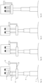
- Fig. 2a-2d shows an embodiment of the system according to the invention, where the current collector and slotted element are shown at different relative positions.
- the embodiment corresponds to what is shown in fig. 1 and the figure references correspond, but it is simplified by comprising only one guiding wheel 12 rather than two wheels 12a, 12b as in fig. 1 .
- the tracking device is "roughly" aligned with the slotted element. Such rough alignment can be achieved by means of positions sensors, which may be magnetic. Precise alignment is achieved by displacing the guiding wheel 12 laterally towards the body part 11 of the tracking device by means of actuator 13.
- the guiding wheel 12 is in abutment with a laterally facing side portion.
- the actuator 13 has further withdrawn, which means that the body portion 11 and collector arm 8 has been displaced to the right until the guiding wheel has reached its withdrawn position where the contact elements 7 are aligned with the slots 6 and the electric conductors.
- the telescopic collector arm 8 has been extended such that contact elements make contact with the conductors. It is understood that the alignment steps illustrated by fig. 2a-2d are typically controlled by an electronic control unit (ECU).
- ECU electronice control unit
- Fig. 3 shows a perspective view of parts of another embodiment of the system according to the invention (shown without the at least one slotted element).
- the tracking device 110 comprises four guiding wheels 115a-d, two on either side of the slotted element, which guiding wheels are laterally displaceable relative the body part 111 of the tracking device.
- Two contact elements 106 each co-acting with a corresponding electric conductor.
- the tracking device is furthermore provided with vertical guiding wheels 114a-d arranged to roll against a downwardly facing portion of the slotted element (assuming a vertical alignment thereof).
- the alignment actuator (not shown) of the tracking device is electrical (comprises a motor), but may in other embodiments for example be hydraulic. The alignment actuator displaces the two pairs of guiding wheels towards and away from each other.
- the collector arm 108 is telescopic and is rotationally connected at its first/upper end to the tracking device.
- the lower/second end of the current collector is connected via rotational connection means in the form of a hinge joint 118 to a sliding device 120.
- a hydraulic actuator 109a is configured to rotate the current collector around the rotational axis defined by the rotational connection means.
- a further hydraulic actuator 109b is configured to rotate the tracking device relative the collector arm.
- the sliding device 120 arranged at the second end of the collector arm is configured to allow lateral movement of the collector arm relative the vehicle.
- Fig. 4 shows a side view of the embodiment in fig. 3 with its telescopic collector arm extended to two different lengths
- Fig. 5 shows a side view of parts of yet another embodiment of the system according to the invention (shown without the at least one slotted element).
- the embodiment corresponds to that shown in figs. 3-4 , but differs in that the collector arm is formed from two serially arranged arm segments 308a, 308b.
- Arm segment 308a corresponds to the telescopic arm 108 in fig. 3 , and is connected via a sliding device 320 (to allow relative lateral movement between the two arm segments) and a hinge joint to the lower arm segment 308b which is in turn is connectable to the vehicle via a lower hinge joint.
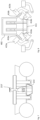
- Fig. 6 shows a tracking device of another embodiment of the system which corresponds to the embodiment in fig. 3 except for the tracking device being different.
- the guiding wheels 215a-d are shown in extended and withdrawn positions
- fig. 7 shows a side view of the tracking device in fig. 6 illustrating the vertical movement of the alignment bar 213'.
- a total of four contact elements 206, where two co-act with each electric conductor, are connected to the body part 211.
- the alignment actuator of the tracking device is a mechanical actuator 213 comprising an alignment bar 213' having a length in the lateral direction being equal to or greater than the distance between the guiding wheels in their extended positions (first distance).
- the alignment bar is displaceable vertically relative the body part 211 and is mechanically connected to the guiding wheels to displace the two pairs of guiding wheels towards each other when the alignment bar is pushed towards the body part.
- the mechanical connection may for example be achieved by means of a desmodromic type of cam arrangement, i.e. the downwards movement of the alignment bar incurs a rotation of a cam which in turn pulls the guiding wheels inwards.
- Fig. 8 shows a cross-section view of parts of yet another embodiment of the system according to the invention (shown without collector arm and parts of the tracking device).
- This embodiment is similar to those shown in figs. 3-5 but differs mainly in that the slotted element 402 is provided with flanges 416a, 416b at both lateral sides.
- the flanges extend along the lengthwise direction of the elongated slotted element.
- the guiding wheels 415a, 415b are angled such that they roll onto the flanges 416a-b to support the tracking device vertically, which means that it is not necessary to force the tracking device upwards once the guiding wheels have engaged with the flanges.
- the vertical guiding wheels 414a-b are also angled to roll against opposite lower sides of the flanges.
- the guiding wheels 415a-b are rotatably connected to L-shaped holding elements which are in turn rotatably connected to the body part (not shown) such that the guiding wheels are laterally displaceable between extended positions (angled out) as shown with solid lines, and withdrawn positions (angled in) as shown with dotted lines when making contact with the flanges. This means that the tracking device can be aligned with the slotted element by means of upwards movement together with inwards displacement of the guiding wheels.
- Fig. 9a-d shows parts of yet another embodiment of the system according to the invention (shown without the collector arm, which may be of the type shown in fig. 3/4 or fig. 5 ), where the tracking device 510 is shown in four different positions relative the slotted element 502.
- the slotted element is seen in a cross-section, and the longitudinal end of the current collector is seen.
- the elongated slotted element 502 differs from the above-described embodiments in that it comprises chamfered guiding edges 516a, 516c at the top of the laterally facing portions 502', 502" of the slotted element, and chamfered aligning edges 516b, 516d at the bottom.
- the edges are chamfered at 45 degrees angle relative the direction of movement of the contact elements, which in the shown vertical alignment equals to 45 degrees relative a vertical plane.
- the elongated slotted element comprises two electric conductors 505 arranged in respective slots 507 in the elongated slotted element. In other embodiments, there may be only one electric conductor, alternatively three or more electric conductors.
- the tracking device 510 comprises two sets of aligning wheels 514a, 514b on each lateral side thereof (only one set on each side can be seen in fig. 9a-d ), the aligning wheels being stationary (apart from rolling motion) relative the body part 511.
- the aligning wheels are angled at 45 degrees such as to be able to roll against the chamfered aligning edges 516b, 516d.
- the aligning wheels thus form vertical guiding means.
- they also form lateral guiding means by means of upwards movement of the tracking device and sliding action of the aligning wheels against the chamfered aligning edges.
- each set of aligning wheels comprise three parallel wheels arranged to rotate around respective common axes of rotation 514a', 514b'.
- the tracking device 510 further comprises two sets of guiding wheels 515a, 515b on each lateral side of the body part 511 (only one set on each side can be seen in fig. 9a-d ), the guiding wheels being arranged laterally outside the aligning wheels 514a, 514b.
- the guiding wheels are laterally displaceable relative the body part by means of being rotatably attached to a respective holding element 517a, 517b which is pivotable/rotatable relative the body part around axes of rotation (axis of rotation 517' of holding element 517a is seen in fig. 10 ) which are perpendicular with the corresponding axes of rotation 515a', 515b' of the guiding wheels.
- the tracking device is aligned with the slotted element, as shown in fig. 9c and 9d , the axes of rotation of the holding elements are substantially parallel with the lengthwise direction of the slotted element.
- the aligning wheels 514a, 514b and the guiding wheels 515a, 515b have the same diameter, and in the extended positions of the guiding wheels as shown in fig. 9a , the axis of rotation 514a', 514b' of the alignment wheels and the axis of rotation 515a', 515b' of the guiding wheels on the respective side lie in the same plane, which plane is disposed at the same angle as the chamfered aligning edges (45 degrees in this embodiment). Consequently, each of the guiding surfaces 515a", 515b" formed by the guiding wheels lie in the same plane as the corresponding aligning surfaces 514a", 514b" formed by the aligning wheels.
- the alignment actuators 517c, 517d of the tracking device are pneumatic cylinders, but may in other embodiments for example be electric, hydraulic or other actuation means that may be applied by those skilled in that art. Further, the actuator may be wire-operated or the like, i.e. an actuator that gets its movement via for example wires from a source of power disposed at a distance.
- the alignment actuators pivot/rotate the holding elements such that the guiding wheels are displaced towards and away from the slotted element.
- the current collector comprises two sets of contact elements 506, each set of contact element being adapted to co-act with a corresponding electric conductor 505 in the slotted element 502.
- the contact elements are connected to the body part 511 by means of a displacement device 518 which is shown in more detail in fig. 10 .
- the displacement device is configured to displace the contact elements towards and away from the body part 511, i.e. in a direction towards and away from the slotted element when the current collector is laterally aligned therewith.
- the current collector in fig. 9a-d aligns with the slotted element as follows.
- the current collector has been roughly laterally aligned with the slotted element by means of the collector arm, whereafter a control system orders the tracking device 510 to be displaced towards the slotted element by means of the collector arm such that the uppermost of guiding wheels 515a makes contact with the chamfered aligning edge 516b.
- the tracking device is displaced further upwards such that the first the guiding wheels 515a, and thereafter the aligning wheels 514a slide on the chamfered aligning edge 516b until the position shown in fig. 9b is achieved.
- both the guiding wheels and the aligning wheels have an aligning function.
- the sliding motion has been stopped by means of the lowermost of alignment wheels 514b having come into contact with chamfered aligning edge 516d.
- the current collector with its tracking device is now laterally aligned with the slotted element.
- the control system receives signals from position sensors 519a, 519b indicating that the current collector is laterally and vertically aligned, whereafter the control system orders the alignment actuators 517c, 517d to pivot the holding elements 517a, 517b until the guiding wheels 515a, 515b make contact with the respective chamfered guiding edges in the position shown in fig. 9c .
- the axes of rotation 515a', 515b' of the guiding wheels are now angled at corresponding angles as the chamfered guiding edges 516a, 516c. Thereafter, the control system orders actuator 518a (see fig.
- fig. 10 shows a cross-section view of parts of the embodiment in fig. 9a-d .
- the cross-section is taken in a vertical plane through the rightmost contact element 506 as seen in fig. 9a-d .
- the contact element 506 is formed form a plurality of consecutively arranged plate-shaped elements, each being resiliently connected (by means of spring members 518e for example) to an elongated base part 518d of displacement device 518.
- the base part is connected to the body part 511 of the tracking device by means of two parallel and pivotable rods 518b, 518c which are rotatably connected at respective ends thereof to the base part and the body part.
- an actuator in the form of a pneumatic cylinder 518a is connected between the base part and the body part such as to displace the base part 518d towards and away from the body part 511.
- the actuator may be hydraulic, electric or other means of actuation such as a wire-operated actuator or the like, i.e. an actuator that gets its movement via for example wires from a source of power disposed at a distance.
- two sets of aligning wheels 514a are disposed longitudinally spaced apart at opposite longitudinal sides of the holding element 517a.
- two sets of guiding wheels 515a are fitted longitudinally spaced apart on the holding element 517a. In other embodiments, only one set or more than two sets of guiding/aligning wheels are provided on each lateral side of the tracking device.
- the ground contact element makes contact before the main contact elements. This is achieved by all of the individual plate-shaped elements of contact elements 506 and ground contact elements 506' being preloaded with one or more springs (518a for example) that is allowed to compress. This compression spring also allows for un-even wear of individual contact elements, which may also be referred to as "brushes", allowing all contact elements to be seated against the respective electric conductor. Actuator 518a applies a controlled force to ensure the correct contact force is maintained to the brush carrier assembly, the individual brush springs then allow each brush to maintain an even individual force to the electric conductors.
- springs 518a for example
- control system which may be an electronic control system, it is not illustrated in the figures since such systems are well known in the art.
- tracking devices of one embodiment may be combined with collector arms from other embodiments.
- the edges of the slotted element in fig. 9a-d are not necessarily chamfered at 45 degrees.
- the orientation may be any angle from the vertical plane.
- wheels may be sliders, skid plates, magnets or in fact any other means of providing the function of the wheels as described.
- the individual contact element springs may be another device or devices such as pneumatic energizers, rubber or other devices that can apply a controlled and known force to each brush.
- the number of electric conductors (and contact elements) may be one or more.
Landscapes
- Engineering & Computer Science (AREA)
- Mechanical Engineering (AREA)
- Power Engineering (AREA)
- Transportation (AREA)
- Life Sciences & Earth Sciences (AREA)
- Sustainable Development (AREA)
- Sustainable Energy (AREA)
- Current-Collector Devices For Electrically Propelled Vehicles (AREA)
- Arrangements For Transmission Of Measured Signals (AREA)
- Elimination Of Static Electricity (AREA)
- Non-Adjustable Resistors (AREA)
Claims (16)
- System zur elektrischen Energieversorgung zumindest eines elektrisch angetriebenen Fahrzeugs (1), umfassend:mindestens ein längliches geschlitztes Element (2; 402; 502), das aufgehängt und so angepasst ist, dass es sich entlang eines Straßenabschnitts (3) erstreckt, auf dem das mindestens eine Fahrzeug so angepasst ist, dass es mit seiner Längsrichtung im Wesentlichen parallel zur Fahrtrichtung fährt, wobei das längliche geschlitzte Element mindestens einen elektrischen Leiter (5; 505) umfasst, der in mindestens einem Schlitz (7; 507) in dem länglichen geschlitzten Element angeordnet ist und der so angepasst ist, dass er elektrisch gespeist wird;mindestens ein Stromabnehmer (4), der so angepasst ist, dass er mit dem mindestens einen aufgehängten länglichen geschlitzten Element (2) zusammenwirkt, wobei der Stromabnehmer Folgendes umfasstmindestens ein Kontaktelement (6; 206; 506), das so angepasst ist, dass es sich elektrisch mit dem mindestens einen entsprechenden elektrischen Leiter (5; 505) des länglichen geschlitzten Elements verbindet;mindestens einen Abnehmerarm (8; 108; 308a-b), der an seinem ersten Ende (8') das mindestens eine Kontaktelement stützt und so angepasst ist, dass er sich an seinem zweiten Ende (8'') direkt oder indirekt mit einem elektrisch treibfähigen Fahrzeug verbindet, undmindestens einen Aktuator (9; 109a-b), der so konfiguriert ist, dass er auf den mindestens einen Abnehmerarm einwirkt, um das erste Ende (8') in Richtung des mindestens einen aufgehängten länglichen geschlitzten Elements zu verschieben,wobei das Kontaktelement (6; 106; 206; 506) mit dem mindestens einen Abnehmerarm durch eine Verfolgungsvorrichtung (10; 110; 510) verbunden ist, wobei die Verfolgungsvorrichtung ein Körperteil (11; 111; 211; 411; 511) umfasst, mit dem das mindestens eine Kontaktelement verbunden ist,dadurch gekennzeichnet, dass die Verfolgungsvorrichtung ferner Mittel zur seitlichen Führung umfasst, umfassend mindestens zwei Führungsräder (12a-b; 115a-d; 215a-d; 415a-b; 515a-b) oder Gleitelemente, die so konfiguriert sind, dass sie gegen seitlich zugewandte Flächenabschnitte (2', 2", 502', 502") an beiden seitlichen Seiten an einem Außenabschnitt (502') des länglichen geschlitzten Elements (2; 502) rollen oder gleiten, um die Verfolgungsvorrichtung seitlich relativ zu dem länglichen geschlitzten Element zu führen, wobei die mindestens zwei Führungsräder oder Gleitelemente durch einen Ausrichtaktuator (13) relativ zu dem Körperteil seitlich verschiebbar sind.
- System nach einem der vorhergehenden Ansprüche, wobei die Verfolgungsvorrichtung (110) ferner Mittel zur vertikalen Führung (114a-114d; 514a-b) umfasst, die so konfiguriert sind, dass sie mit dem länglichen geschlitzten Element zusammenwirken, um die Verfolgungsvorrichtung vertikal relativ zu dem länglichen geschlitzten Element zu führen.
- System nach einem der vorhergehenden Ansprüche, wobei die mindestens zwei Führungsräder (12a-b; 115a-d; 215a-d; 415a-b; 515a-b) oder Gleitelemente relativ zum Körperteil (11; 111; 211; 411; 511) durch den Ausrichtaktuator (13, 213) zwischen ausgefahrenen Positionen seitlich verschiebbar sind, in denen die Führungselemente oder -räder mit einer ersten Entfernung voneinander beabstandet sind, die größer als die laterale Breite des länglichen geschlitzten Elements und zurückgezogenen Positionen ist, in denen die Führungselemente oder -räder mit einer der seitlichen Breite entsprechenden zweiten Entfernung voneinander beabstandet sind.
- System nach Anspruch 3, wobei der Ausrichtaktuator (213) der Verfolgungsvorrichtung ein mechanischer Aktuator ist, umfassend einen Ausrichtbalken (213'), der in der lateralen Richtung eine Länge hat, die gleich oder größer als die erste Entfernung ist, wobei der Ausrichtbalken relativ zu dem Körperteil (211) verschiebbar ist und mechanisch mit den Führungsrädern oder Gleitelementen (215a-215d) derart verbunden ist, dass er die mindestens zwei Führungsräder oder Gleitelemente zueinander verschiebt, wenn der Ausrichtbalken in Richtung des Körperteils geschoben wird
- System nach einem der vorhergehenden Ansprüche, wobei dem länglichen geschlitzten Element (402) ein Flansch (416a, 416b) oder eine Nut an mindestens einer seitlichen Seite bereitgestellt wird, wobei sich der Flansch oder die Nut entlang der Längsrichtung des länglichen geschlitzten Elements erstreckt und dazu konfiguriert ist, mindestens Teile der Führungsräder oder Gleitelemente (415a, 415b) daran oder darin aufzunehmen, um die Verfolgungsvorrichtung zu stützen, wenn die Führungsräder oder Gleitelemente an dem länglichen geschlitzten Element anliegen.
- System nach einem der vorhergehenden Ansprüche, wobei der Abnehmerarm (8; 108; 308a) ein Teleskoparmsegment umfasst, das direkt oder indirekt mit einem Fahrzeug verbindbar ist, wobei der mindestens eine Aktuator (9; 109a) einen Aktuator umfasst, der zum Ausfahren und Zurückziehen des Teleskoparmsegments konfiguriert ist.
- System nach einem der vorhergehenden Ansprüche, wobei der Stromabnehmer Mittel zur Drehverbindung (118) zum direkten oder indirekten drehbaren Verbinden des zweiten Endes des Abnehmerarms mit einem Fahrzeug umfasst, wobei der mindestens eine Aktuator einen Aktuator (109a) umfasst, der so konfiguriert ist, dass er den Stromabnehmer um eine durch die Mittel zur Drehverbindung (118) definierte Drehachse dreht.
- System nach einem der vorhergehenden Ansprüche, wobei das System ferner eine Gleitvorrichtung (120) umfasst, die an dem zweiten Ende des Abnehmerarms (108) angeordnet ist, wobei die Gleitvorrichtung so konfiguriert ist, dass sie eine seitliche Bewegung des Abnehmerarms relativ zu einem Fahrzeug ermöglicht, oder wobei der Abnehmerarm durch mindestens zwei seriell angeordnete Armsegmente gebildet ist, umfassend erste und zweite Armsegmente (308a, 308b), ferner umfassend eine Gleitvorrichtung (320), die zwischen dem ersten und zweiten Armsegment angeordnet ist, wobei die Gleitvorrichtung so konfiguriert ist, dass sie eine seitliche Bewegung des ersten Armsegments relativ zu dem zweiten Armsegment ermöglicht.
- System nach Anspruch 3, wobei der Ausrichtaktuator (13) der Verfolgungsvorrichtung (10) ein elektrischer, hydraulischer oder pneumatischer Aktuator ist, wobei das System ferner eine elektronische Steuereinheit und mindestens einen damit verbundenen Positionssensor umfasst, wobei die elektronische Steuereinheit so konfiguriert ist, dass sie:den Ausrichtaktuator derart steuert, dass die Führungsräder oder Gleitelemente in ihre ausgefahrenen Positionen verschoben werden;nachdem die Führungsräder oder Gleitelemente in ihre ausgefahrenen Positionen verschoben wurden und als Reaktion auf Signale von dem mindestens einen Positionssensor, den mindestens einen Aktuator derart steuert, dass die Verfolgungsvorrichtung mit dem geschlitzten Element zwischen den Führungsrädern oder Gleitelementen ausgerichtet ist;nachdem die Verfolgungsvorrichtung mit dem geschlitzten Element ausgerichtet wurde, den Ausrichtaktuator steuert, um die Führungsräder oder Gleitelemente seitlich nach innen in Richtung des geschlitzten Elements zu verschieben, bis das mindestens eine Kontaktelement seitlich mit dem mindestens einen entsprechenden elektrischen Leiter ausgerichtet ist, undnachdem das Kontaktelement seitlich mit dem mindestens einen entsprechenden elektrischen Leiter ausgerichtet wurde, den mindestens einen Aktuator steuert, um die Verfolgungsvorrichtung in Richtung des geschlitzten Elements zu verschieben, bis das mindestens eine Kontaktelement in Kontakt mit dem mindestens einen entsprechenden elektrischen Leiter ist.
- System nach einem der Ansprüche 1 bis 4 oder einem der Ansprüche 6 bis 8, abhängig von einem der Ansprüche 1 bis 4, wobei jedem seitlich zugewandten Flächenabschnitt (502', 502") des geschlitzten Elements (502) eine Ausrichtkante (516b, 516d) an dem Boden davon bereitgestellt wird und wobei die Verfolgungsvorrichtung (510) mindestens einen Satz von Ausrichträdern oder Gleitelementen (514a, 514b) an jeder seitlichen Seite davon umfasst, wobei die Ausrichträder oder Gleitelemente an jeder seitlichen Seite angeordnet sind, um eine entsprechende Ausrichtfläche (514a", 514b") zu bilden, die so angeordnet ist, dass sie seitlich gegen die jeweiligen Ausrichtkanten (516b, 516d) am Boden der seitlich zugewandten Flächenabschnitte gleitet, wobei die Ausrichträder oder Gleitelemente ferner mit einer derartigen Entfernung voneinander beabstandet sind, dass mindestens ein Ausrichtrad oder Gleitelement (514a, 514b) jedes Satzes von Ausrichträdern oder Gleitelementen gegen eine entsprechende Ausrichtkante (516b, 516d) am Boden der seitlich zugewandten Flächenabschnitte rollen oder gleiten kann,
wobei die Führungsräder oder Gleitelemente (515a, 515b) relativ zu dem Körperteil (511) zwischen ausgefahrenen Positionen seitlich verschiebbar sind, in denen die Führungsräder oder Gleitelemente mit einer ersten Entfernung voneinander beabstandet sind, die größer oder gleich der seitlichen Breite des länglichen geschlitzten Elements (502) ist, und zurückgezogenen Positionen, in denen die Führungsräder oder Gleitelemente in einer derartigen Entfernung voneinander angeordnet sind, dass die Führungsräder oder Gleitelemente gegen jeweilige seitliche Abschnitte rollen oder gleiten. - System nach Anspruch 10, wobei die Ausrichtkanten abgeschrägt sind und wobei die Ausrichträder um Drehachsen (514a', 514b') drehbar sind, die in entsprechenden Winkeln wie die abgeschrägten Ausrichtkanten angeordnet sind.
- System nach Anspruch 10 oder 11, wobei fernerhin mindestens einem seitlich zugewandten Flächenabschnitt (502', 502") des geschlitzten Elements (502) eine Führungskante (516a, 516c) an der Oberseite davon bereitgestellt wird und wobei die Führungsräder oder Gleitelemente (515a, 515b) relativ zum Körperteil (511) dadurch seitlich verschiebbar sind, dass sie durch Halteelemente (517a, 517b) an den seitlichen Seiten der Verfolgungsvorrichtung gestützt werden, deren Halteelemente relativ zum Körperteil um jeweilige Drehachsen (517a') drehbar sind, die im Wesentlichen parallel zur Längsrichtung sind, wobei mindestens ein Satz von Führungsrädern oder Gleitelementen in der zurückgezogenen Position so ausgerichtet ist, dass er mit der entsprechenden Führungskante (516a, 516c) an der Oberseite des seitlich zugewandten Flächenabschnitts zusammenwirkt, und wobei die Führungsräder oder Gleitelemente in den zurückgezogenen Positionen in einer derartigen Entfernung voneinander beabstandet sind, dass der mindestens eine Satz von Führungsrädern oder Gleitelementen auf der Führungskante rollt oder gleitet.
- System nach Anspruch 12, wobei die Führungskanten abgeschrägt sind und wobei die Führungsräder um Drehachsen (515a', 515b') drehbar sind, die in entsprechenden Winkeln als die Führungskanten angeordnet sind.
- System nach einem der Ansprüche 10 bis 13, wobei die Führungsräder oder Gleitelemente (515a, 515b) an jeder seitlichen Seite eine jeweilige Führungsfläche (515a", 515b") bilden und wobei die Ausrichträder oder Gleitelemente und die Führungsräder oder Gleitelemente derart ausgerichtet sind, dass in den ausgefahrenen Positionen der Führungsräder oder Gleitelemente jede Ausrichtfläche (514a", 514b") der Ausrichträder oder Gleitelemente und die Führungsfläche der benachbarten Führungsräder oder Gleitelemente in einer gemeinsamen Ebene angeordnet sind.
- System nach einem der Ansprüche 10 bis 14, wobei das mindestens eine Kontaktelement mit dem Körperteil durch eine Verschiebevorrichtung (518) verbunden ist, die so konfiguriert ist, dass sie die Kontaktelemente relativ zu dem Körperteil in einer Richtung zu und weg von dem Körperteil (511) verschiebt.
- System nach einem der Ansprüche 1 bis 4 oder einem der Ansprüche 6 bis 8, abhängig von einem der Ansprüche 1 bis 4, wobei mindestens einem seitlich zugewandten Flächenabschnitt (502', 502") an dem Außenabschnitt des geschlitzten Elements (502) eine Führungskante (516a, 516c) an der Oberseite davon bereitgestellt wird und wobei die Führungsräder oder Gleitelemente (515a, 515b) relativ zum Körperteil (511) dadurch seitlich verschiebbar sind, dass sie durch Halteelemente (517a, 517b) an den seitlichen Seiten der Verfolgungsvorrichtung gestützt werden, deren Halteelemente relativ zum Körperteil um jeweilige Drehachsen (517a') drehbar sind, die im Wesentlichen parallel zur Längsrichtung sind, wobei mindestens ein Satz von Führungsrädern oder Gleitelementen in der zurückgezogenen Position so ausgerichtet ist, dass er mit der entsprechenden Führungskante (516a, 516c) an der Oberseite des seitlich zugewandten Flächenabschnitts zusammenwirkt, und wobei die Führungsräder oder Gleitelemente in den zurückgezogenen Positionen in einer derartigen Entfernung voneinander beabstandet sind, dass der mindestens eine Satz von Führungsrädern oder Gleitelementen auf der Führungskante rollt oder gleitet.
Priority Applications (1)
| Application Number | Priority Date | Filing Date | Title |
|---|---|---|---|
| EP25183441.2A EP4596297A3 (de) | 2020-11-05 | 2021-11-05 | System zur elektrischen speisung mindestens eines elektrisch angetriebenen fahrzeugs |
Applications Claiming Priority (2)
| Application Number | Priority Date | Filing Date | Title |
|---|---|---|---|
| PCT/EP2020/081199 WO2022096115A1 (en) | 2020-11-05 | 2020-11-05 | System for electrically feeding at least one electrically powered vehicle |
| PCT/EP2021/080811 WO2022096665A1 (en) | 2020-11-05 | 2021-11-05 | System for electrically feeding at least one electrically powered vehicle |
Related Child Applications (1)
| Application Number | Title | Priority Date | Filing Date |
|---|---|---|---|
| EP25183441.2A Division EP4596297A3 (de) | 2020-11-05 | 2021-11-05 | System zur elektrischen speisung mindestens eines elektrisch angetriebenen fahrzeugs |
Publications (3)
| Publication Number | Publication Date |
|---|---|
| EP4240610A1 EP4240610A1 (de) | 2023-09-13 |
| EP4240610B1 true EP4240610B1 (de) | 2025-06-18 |
| EP4240610C0 EP4240610C0 (de) | 2025-06-18 |
Family
ID=73138850
Family Applications (2)
| Application Number | Title | Priority Date | Filing Date |
|---|---|---|---|
| EP25183441.2A Pending EP4596297A3 (de) | 2020-11-05 | 2021-11-05 | System zur elektrischen speisung mindestens eines elektrisch angetriebenen fahrzeugs |
| EP21807056.3A Active EP4240610B1 (de) | 2020-11-05 | 2021-11-05 | System zur elektrischen energieversorgung zumindest eines elektrisch angetriebenen fahrzeugs |
Family Applications Before (1)
| Application Number | Title | Priority Date | Filing Date |
|---|---|---|---|
| EP25183441.2A Pending EP4596297A3 (de) | 2020-11-05 | 2021-11-05 | System zur elektrischen speisung mindestens eines elektrisch angetriebenen fahrzeugs |
Country Status (7)
| Country | Link |
|---|---|
| US (1) | US20240010073A1 (de) |
| EP (2) | EP4596297A3 (de) |
| CN (1) | CN116685496A (de) |
| AU (1) | AU2021374029A1 (de) |
| CA (1) | CA3197611A1 (de) |
| PE (1) | PE20250823A1 (de) |
| WO (2) | WO2022096115A1 (de) |
Families Citing this family (2)
| Publication number | Priority date | Publication date | Assignee | Title |
|---|---|---|---|---|
| WO2025255309A1 (en) * | 2024-06-07 | 2025-12-11 | Caterpillar Inc. | A mobile machine power conductor linkage for receiving power from a power conductor rail assembly |
| EP4714719A1 (de) | 2024-09-23 | 2026-03-25 | Bluvein Innovation Pty. Ltd. | System und verfahren zur elektrischen speisung von elektrisch angetriebenen fahrzeugen |
Citations (1)
| Publication number | Priority date | Publication date | Assignee | Title |
|---|---|---|---|---|
| US6264017B1 (en) * | 1999-06-25 | 2001-07-24 | Woodhead Industries, Inc. | Multi-conductor power bar system and trolley therefor |
Family Cites Families (21)
| Publication number | Priority date | Publication date | Assignee | Title |
|---|---|---|---|---|
| US3727729A (en) * | 1970-10-06 | 1973-04-17 | Merlin Gerin | Multi-phase electrical distribution and current collecting system for high speed vehicles |
| US3730311A (en) * | 1971-03-10 | 1973-05-01 | Rohr Industries Inc | Collector sled and mounting structure therefor for high speed, track mounted electric vehicle |
| JPS5820814B2 (ja) * | 1978-09-07 | 1983-04-25 | 日産自動車株式会社 | ル−プ状給電トロリの給電装置 |
| DE3245601C2 (de) * | 1982-12-09 | 1986-11-27 | Wampfler Gmbh, 7858 Weil | Vorrichtung zum Abgriff von Strom für ein Fahrzeug |
| EP2296933B1 (de) * | 2008-07-01 | 2016-10-05 | Proterra Inc. | Aufladestationen für elektrofahrzeuge |
| CN102917907A (zh) * | 2009-12-23 | 2013-02-06 | 普罗特拉公司 | 用于电动车辆的充电站 |
| SE1000324A1 (sv) * | 2010-04-01 | 2011-03-22 | Elways Ab | Ett, för ett eller flera, elektriskt framdrivbara fordon anpassat system (Kontaktmedel) |
| SE536908C2 (sv) * | 2013-01-18 | 2014-10-28 | Enega AB | Anordning för att åstadkomma eldrift av tunga fordon |
| EP3427997B1 (de) * | 2013-11-06 | 2020-07-08 | Honda Motor Co., Ltd. | Kontaktladegeräte mit ladearm und kontaktladesystem für elektrofahrzeug |
| HUP1400184A2 (hu) * | 2014-04-02 | 2015-10-28 | Dalma Bartalosova | Alsó áramszedésre és kisiklásbiztosan kötött pályás üzemre képes elektromos meghajtású jármû |
| DE102014219178A1 (de) * | 2014-09-23 | 2016-03-24 | Bayerische Motoren Werke Aktiengesellschaft | Zellkontaktiersystem eines Kraftfahrzeugbatteriemoduls sowie Kraftfahrzeugbatteriemodul |
| US10720683B2 (en) * | 2014-09-30 | 2020-07-21 | Cps Technology Holdings Llc | Battery module thermal management features for internal flow |
| SE538900C2 (sv) | 2015-04-27 | 2017-01-31 | Elways Ab | System and method for electrical feeding of a vehicle |
| WO2018087564A1 (en) * | 2016-11-10 | 2018-05-17 | Algret Yannick | Electricity collector device |
| EP3815953B1 (de) * | 2019-10-30 | 2022-05-04 | Elways AB | Elektrisch antreibbares fahrzeug, einen stromabnehmer umfassend |
| US20210253193A1 (en) * | 2020-02-17 | 2021-08-19 | Chengbang Liu | Smart electric scooter with communication capabilities |
| DE102020202616A1 (de) * | 2020-03-02 | 2021-09-02 | Robert Bosch Gesellschaft mit beschränkter Haftung | Antriebseinheit für einen selbstfahrenden Wagen, selbstfahrender Wagen, Tragstruktur für selbstfahrende Wagen und Transportsystem |
| SE544156C2 (en) * | 2020-06-09 | 2022-02-08 | Scania Cv Ab | An apparatus for the electrical charging of an electrical battery unit of a vehicle |
| BR112023018470A2 (pt) * | 2021-03-12 | 2023-11-14 | Bluvein Innovation Pty Ltd | Sistema para alimentar eletricamente veículos acionados eletricamente |
| EP4366973A4 (de) * | 2021-07-09 | 2025-04-23 | Bluvein Innovation Pty. Ltd. | Elektrofahrzeug für hochleistungsanwendungen |
| SE545770C2 (en) * | 2022-09-05 | 2024-01-09 | Evias Ab | System comprising at least one electrically propellable vehicle |
-
2020
- 2020-11-05 WO PCT/EP2020/081199 patent/WO2022096115A1/en not_active Ceased
-
2021
- 2021-11-05 WO PCT/EP2021/080811 patent/WO2022096665A1/en not_active Ceased
- 2021-11-05 CN CN202180088173.1A patent/CN116685496A/zh active Pending
- 2021-11-05 CA CA3197611A patent/CA3197611A1/en active Pending
- 2021-11-05 PE PE2025000212A patent/PE20250823A1/es unknown
- 2021-11-05 AU AU2021374029A patent/AU2021374029A1/en active Pending
- 2021-11-05 EP EP25183441.2A patent/EP4596297A3/de active Pending
- 2021-11-05 US US18/035,688 patent/US20240010073A1/en active Pending
- 2021-11-05 EP EP21807056.3A patent/EP4240610B1/de active Active
Patent Citations (1)
| Publication number | Priority date | Publication date | Assignee | Title |
|---|---|---|---|---|
| US6264017B1 (en) * | 1999-06-25 | 2001-07-24 | Woodhead Industries, Inc. | Multi-conductor power bar system and trolley therefor |
Also Published As
| Publication number | Publication date |
|---|---|
| EP4240610A1 (de) | 2023-09-13 |
| US20240010073A1 (en) | 2024-01-11 |
| EP4596297A3 (de) | 2025-10-01 |
| PE20250823A1 (es) | 2025-03-20 |
| CA3197611A1 (en) | 2022-05-12 |
| WO2022096665A1 (en) | 2022-05-12 |
| AU2021374029A9 (en) | 2024-09-05 |
| AU2021374029A1 (en) | 2023-06-15 |
| CN116685496A (zh) | 2023-09-01 |
| EP4596297A2 (de) | 2025-08-06 |
| WO2022096115A1 (en) | 2022-05-12 |
| EP4240610C0 (de) | 2025-06-18 |
Similar Documents
| Publication | Publication Date | Title |
|---|---|---|
| EP4240610B1 (de) | System zur elektrischen energieversorgung zumindest eines elektrisch angetriebenen fahrzeugs | |
| AU2024100050A4 (en) | System for electrically feeding at least one electrically powered vehicle | |
| EP2819876B1 (de) | Stromübertragungsvorrichtung zur aufladung elektrischer energiespeicher von fahrzeugen an überkopfladestationen | |
| US10017062B2 (en) | Electric charging device, electric connection device, system and method for charging a battery of a vehicle | |
| CN108136917B (zh) | 用于将车辆电连接到充电站的快速充电系统和方法 | |
| CN104245406A (zh) | 用于电动车辆的充电的连接系统 | |
| EP2701940A2 (de) | Nicht schienengebundenes fahrzeug mit einem strohmabnehmer | |
| US20250026243A1 (en) | Relocatable base for elevated power rails and method of deployment | |
| SE537626C2 (sv) | Strömavtagare | |
| WO2016174030A1 (en) | System and method for electrical feeding of a vehicle | |
| US20240001771A1 (en) | System and method for supporting elevated power rails | |
| EP3815953B1 (de) | Elektrisch antreibbares fahrzeug, einen stromabnehmer umfassend | |
| EP4031400A1 (de) | Stationäre ladeanordnung und verfahren zum laden | |
| CN111113448B (zh) | 一种导轨式巡线机器人 | |
| EP4032740A1 (de) | Stromabnehmer-anordnung für doppelpolige fahrdrähte | |
| CN222436022U (zh) | 一种伸缩锁止机构及汽车搬运机器人 | |
| EP4714719A1 (de) | System und verfahren zur elektrischen speisung von elektrisch angetriebenen fahrzeugen | |
| DE102020005533A1 (de) | Vorrichtung zum konduktiven Laden eines elektrisch betriebenen Fahrzeugs | |
| CN116424588A (zh) | 一种多功能桁架、火箭测试及发射设备 | |
| EP3003771A2 (de) | Mechanismus für elektrische versorgung von strassenfahrzeugen | |
| CN106218446A (zh) | 纵臂受电式电动列车 |
Legal Events
| Date | Code | Title | Description |
|---|---|---|---|
| STAA | Information on the status of an ep patent application or granted ep patent |
Free format text: STATUS: UNKNOWN |
|
| STAA | Information on the status of an ep patent application or granted ep patent |
Free format text: STATUS: THE INTERNATIONAL PUBLICATION HAS BEEN MADE |
|
| PUAI | Public reference made under article 153(3) epc to a published international application that has entered the european phase |
Free format text: ORIGINAL CODE: 0009012 |
|
| STAA | Information on the status of an ep patent application or granted ep patent |
Free format text: STATUS: REQUEST FOR EXAMINATION WAS MADE |
|
| 17P | Request for examination filed |
Effective date: 20230602 |
|
| AK | Designated contracting states |
Kind code of ref document: A1 Designated state(s): AL AT BE BG CH CY CZ DE DK EE ES FI FR GB GR HR HU IE IS IT LI LT LU LV MC MK MT NL NO PL PT RO RS SE SI SK SM TR |
|
| DAV | Request for validation of the european patent (deleted) | ||
| DAX | Request for extension of the european patent (deleted) | ||
| GRAP | Despatch of communication of intention to grant a patent |
Free format text: ORIGINAL CODE: EPIDOSNIGR1 |
|
| STAA | Information on the status of an ep patent application or granted ep patent |
Free format text: STATUS: GRANT OF PATENT IS INTENDED |
|
| INTG | Intention to grant announced |
Effective date: 20240319 |
|
| GRAJ | Information related to disapproval of communication of intention to grant by the applicant or resumption of examination proceedings by the epo deleted |
Free format text: ORIGINAL CODE: EPIDOSDIGR1 |
|
| STAA | Information on the status of an ep patent application or granted ep patent |
Free format text: STATUS: REQUEST FOR EXAMINATION WAS MADE |
|
| INTC | Intention to grant announced (deleted) | ||
| GRAP | Despatch of communication of intention to grant a patent |
Free format text: ORIGINAL CODE: EPIDOSNIGR1 |
|
| STAA | Information on the status of an ep patent application or granted ep patent |
Free format text: STATUS: GRANT OF PATENT IS INTENDED |
|
| INTG | Intention to grant announced |
Effective date: 20240905 |
|
| GRAJ | Information related to disapproval of communication of intention to grant by the applicant or resumption of examination proceedings by the epo deleted |
Free format text: ORIGINAL CODE: EPIDOSDIGR1 |
|
| STAA | Information on the status of an ep patent application or granted ep patent |
Free format text: STATUS: REQUEST FOR EXAMINATION WAS MADE |
|
| INTC | Intention to grant announced (deleted) | ||
| GRAP | Despatch of communication of intention to grant a patent |
Free format text: ORIGINAL CODE: EPIDOSNIGR1 |
|
| STAA | Information on the status of an ep patent application or granted ep patent |
Free format text: STATUS: GRANT OF PATENT IS INTENDED |
|
| INTG | Intention to grant announced |
Effective date: 20250109 |
|
| GRAS | Grant fee paid |
Free format text: ORIGINAL CODE: EPIDOSNIGR3 |
|
| GRAA | (expected) grant |
Free format text: ORIGINAL CODE: 0009210 |
|
| STAA | Information on the status of an ep patent application or granted ep patent |
Free format text: STATUS: THE PATENT HAS BEEN GRANTED |
|
| AK | Designated contracting states |
Kind code of ref document: B1 Designated state(s): AL AT BE BG CH CY CZ DE DK EE ES FI FR GB GR HR HU IE IS IT LI LT LU LV MC MK MT NL NO PL PT RO RS SE SI SK SM TR |
|
| REG | Reference to a national code |
Ref country code: GB Ref legal event code: FG4D |
|
| REG | Reference to a national code |
Ref country code: CH Ref legal event code: EP |
|
| REG | Reference to a national code |
Ref country code: DE Ref legal event code: R096 Ref document number: 602021032537 Country of ref document: DE |
|
| REG | Reference to a national code |
Ref country code: CH Ref legal event code: EP |
|
| REG | Reference to a national code |
Ref country code: IE Ref legal event code: FG4D |
|
| U01 | Request for unitary effect filed |
Effective date: 20250630 |
|
| U07 | Unitary effect registered |
Designated state(s): AT BE BG DE DK EE FI FR IT LT LU LV MT NL PT RO SE SI Effective date: 20250711 |
|
| PG25 | Lapsed in a contracting state [announced via postgrant information from national office to epo] |
Ref country code: NO Free format text: LAPSE BECAUSE OF FAILURE TO SUBMIT A TRANSLATION OF THE DESCRIPTION OR TO PAY THE FEE WITHIN THE PRESCRIBED TIME-LIMIT Effective date: 20250918 Ref country code: GR Free format text: LAPSE BECAUSE OF FAILURE TO SUBMIT A TRANSLATION OF THE DESCRIPTION OR TO PAY THE FEE WITHIN THE PRESCRIBED TIME-LIMIT Effective date: 20250919 |
|
| PG25 | Lapsed in a contracting state [announced via postgrant information from national office to epo] |
Ref country code: HR Free format text: LAPSE BECAUSE OF FAILURE TO SUBMIT A TRANSLATION OF THE DESCRIPTION OR TO PAY THE FEE WITHIN THE PRESCRIBED TIME-LIMIT Effective date: 20250618 |
|
| PG25 | Lapsed in a contracting state [announced via postgrant information from national office to epo] |
Ref country code: RS Free format text: LAPSE BECAUSE OF FAILURE TO SUBMIT A TRANSLATION OF THE DESCRIPTION OR TO PAY THE FEE WITHIN THE PRESCRIBED TIME-LIMIT Effective date: 20250918 |
|
| U20 | Renewal fee for the european patent with unitary effect paid |
Year of fee payment: 5 Effective date: 20251110 |
|
| PG25 | Lapsed in a contracting state [announced via postgrant information from national office to epo] |
Ref country code: IS Free format text: LAPSE BECAUSE OF FAILURE TO SUBMIT A TRANSLATION OF THE DESCRIPTION OR TO PAY THE FEE WITHIN THE PRESCRIBED TIME-LIMIT Effective date: 20251018 |
|
| PG25 | Lapsed in a contracting state [announced via postgrant information from national office to epo] |
Ref country code: SM Free format text: LAPSE BECAUSE OF FAILURE TO SUBMIT A TRANSLATION OF THE DESCRIPTION OR TO PAY THE FEE WITHIN THE PRESCRIBED TIME-LIMIT Effective date: 20250618 |
|
| PG25 | Lapsed in a contracting state [announced via postgrant information from national office to epo] |
Ref country code: CZ Free format text: LAPSE BECAUSE OF FAILURE TO SUBMIT A TRANSLATION OF THE DESCRIPTION OR TO PAY THE FEE WITHIN THE PRESCRIBED TIME-LIMIT Effective date: 20250618 |
|
| PG25 | Lapsed in a contracting state [announced via postgrant information from national office to epo] |
Ref country code: PL Free format text: LAPSE BECAUSE OF FAILURE TO SUBMIT A TRANSLATION OF THE DESCRIPTION OR TO PAY THE FEE WITHIN THE PRESCRIBED TIME-LIMIT Effective date: 20250618 |
|
| PG25 | Lapsed in a contracting state [announced via postgrant information from national office to epo] |
Ref country code: SK Free format text: LAPSE BECAUSE OF FAILURE TO SUBMIT A TRANSLATION OF THE DESCRIPTION OR TO PAY THE FEE WITHIN THE PRESCRIBED TIME-LIMIT Effective date: 20250618 |
|
| PG25 | Lapsed in a contracting state [announced via postgrant information from national office to epo] |
Ref country code: ES Free format text: LAPSE BECAUSE OF FAILURE TO SUBMIT A TRANSLATION OF THE DESCRIPTION OR TO PAY THE FEE WITHIN THE PRESCRIBED TIME-LIMIT Effective date: 20250618 |
|
| PLBE | No opposition filed within time limit |
Free format text: ORIGINAL CODE: 0009261 |
|
| STAA | Information on the status of an ep patent application or granted ep patent |
Free format text: STATUS: NO OPPOSITION FILED WITHIN TIME LIMIT |