EP4240133B1 - Tool-carrying group for agricultural machines - Google Patents
Tool-carrying group for agricultural machines Download PDFInfo
- Publication number
- EP4240133B1 EP4240133B1 EP21814880.7A EP21814880A EP4240133B1 EP 4240133 B1 EP4240133 B1 EP 4240133B1 EP 21814880 A EP21814880 A EP 21814880A EP 4240133 B1 EP4240133 B1 EP 4240133B1
- Authority
- EP
- European Patent Office
- Prior art keywords
- tool
- carrying
- shaft
- support
- group
- Prior art date
- Legal status (The legal status is an assumption and is not a legal conclusion. Google has not performed a legal analysis and makes no representation as to the accuracy of the status listed.)
- Active
Links
Images


Classifications
-
- A—HUMAN NECESSITIES
- A01—AGRICULTURE; FORESTRY; ANIMAL HUSBANDRY; HUNTING; TRAPPING; FISHING
- A01B—SOIL WORKING IN AGRICULTURE OR FORESTRY; PARTS, DETAILS, OR ACCESSORIES OF AGRICULTURAL MACHINES OR IMPLEMENTS, IN GENERAL
- A01B33/00—Tilling implements with rotary driven tools, e.g. in combination with fertiliser distributors or seeders, with grubbing chains, with sloping axles, with driven discs
- A01B33/08—Tools; Details, e.g. adaptations of transmissions or gearings
- A01B33/082—Transmissions; Gearings; Power distribution
- A01B33/085—Transmissions; Gearings; Power distribution specially adapted for tools on a vertical shaft
-
- A—HUMAN NECESSITIES
- A01—AGRICULTURE; FORESTRY; ANIMAL HUSBANDRY; HUNTING; TRAPPING; FISHING
- A01B—SOIL WORKING IN AGRICULTURE OR FORESTRY; PARTS, DETAILS, OR ACCESSORIES OF AGRICULTURAL MACHINES OR IMPLEMENTS, IN GENERAL
- A01B23/00—Elements, tools, or details of harrows
- A01B23/04—Frames; Drawing-arrangements
- A01B23/046—Specially adapted for harrows with rotating tools
-
- A—HUMAN NECESSITIES
- A01—AGRICULTURE; FORESTRY; ANIMAL HUSBANDRY; HUNTING; TRAPPING; FISHING
- A01B—SOIL WORKING IN AGRICULTURE OR FORESTRY; PARTS, DETAILS, OR ACCESSORIES OF AGRICULTURAL MACHINES OR IMPLEMENTS, IN GENERAL
- A01B33/00—Tilling implements with rotary driven tools, e.g. in combination with fertiliser distributors or seeders, with grubbing chains, with sloping axles, with driven discs
- A01B33/06—Tilling implements with rotary driven tools, e.g. in combination with fertiliser distributors or seeders, with grubbing chains, with sloping axles, with driven discs with tools on vertical or steeply-inclined shaft
- A01B33/065—Tilling implements with rotary driven tools, e.g. in combination with fertiliser distributors or seeders, with grubbing chains, with sloping axles, with driven discs with tools on vertical or steeply-inclined shaft comprising a plurality of rotors carried by an elongate, substantially closed transmission casing, transversely connectable to a tractor
-
- A—HUMAN NECESSITIES
- A01—AGRICULTURE; FORESTRY; ANIMAL HUSBANDRY; HUNTING; TRAPPING; FISHING
- A01B—SOIL WORKING IN AGRICULTURE OR FORESTRY; PARTS, DETAILS, OR ACCESSORIES OF AGRICULTURAL MACHINES OR IMPLEMENTS, IN GENERAL
- A01B21/00—Harrows with rotary non-driven tools
- A01B21/02—Harrows with rotary non-driven tools with tooth-like tools
- A01B21/06—Harrows with rotary non-driven tools with tooth-like tools on vertically-arranged axles
Definitions
- the present invention relates to a tool-carrying group for agricultural machines, in particular for rotary harrows, and an agricultural machine comprising such a tool-carrying group.
- a tool-carrying group constructed according to the prior art is shown in Figure 1 .
- the group according to the prior art comprises a first flanged element A and a second flanged element B which are fixed to the supporting structure of a machine and which are provided with respective rolling bearings C which rotatably support a mechanical transmission shaft D for a rotational movement.
- a similar tool-carrying group is also described in EP2232972A1 in the name of the same Applicant.
- the problem of supporting a rotor of a rotary harrow has evident difficulties as a result of the harsh operating conditions of the shaft which can be subjected to repeated and variable loading cycles over time.
- the blades which operate on the ground transmit to the respective blade-carrying shafts mechanical stresses which have a variable magnitude and direction depending on the rotation speed of the rotors, the advance speed of the agricultural machine and the conditions of the ground, as well as any obstacles (stones, stumps, pieces of wood and the like). Therefore, the tool-carrying groups have to be structurally rigid and particularly resistant in order to support the stresses transmitted by the respective blade-carrying shafts.
- the fact that the internal rolling track of the bearing is constructed in one piece in the shaft involves the shaft having to be a special shaft and it not being possible to use a shaft of the conventional type.
- the conventional shafts which are commercially available do not in fact have rolling tracks for rolling elements.
- the tool-carrying group can be loaded in the presence of external contaminants, such as, for example, earth or dust, which are introduced into the rolling bearings, accelerating the wear and reducing the service-life thereof.
- external contaminants such as, for example, earth or dust
- the technical problem addressed by the present invention is to provide a tool-carrying group and an agricultural machine comprising such a tool-carrying group which are structurally and functionally configured to at least partially overcome one or more of the disadvantages set out with reference to the cited prior art.
- an object of the present invention is to provide a tool-carrying group which allows bearings to be replaced without having to replace the entire tool-carrying shaft.
- Another object of the invention is to provide a tool-carrying group which allows the use and simple assembly of a shaft of the conventional type, particularly a shaft without rolling tracks for rolling elements.
- a tool-carrying group for agricultural machines in particular for rotary harrows, comprising two supports which are configured to be mounted axially with spacing on a supporting structure so as to rotatably support a tool-carrying shaft on the supporting structure.
- Each of the two supports includes a flanged element which is configured to be removably secured to the supporting structure and in which an axial seat is defined.
- the two supports are configured to be mounted on the supporting structure with spacing from each other along the axis of the tool-carrying shaft so as to effectively counteract the external stresses which tend to flex the shaft.
- a first support of the supports comprises a first blind seat which is configured to receive a first end of the tool-carrying shaft, and a second support of the supports comprises a second through-seat, the through-hole of which is configured for the passage of the tool-carrying shaft.
- the present invention relates to an agricultural machine comprising at least one tool-carrying group and furthermore a supporting structure to which the tool-carrying group is removably secured, and a tool-carrying shaft which is rotatably supported on the supporting structure by means of the tool-carrying group.
- blade-carrying shaft is intended to be understood to be a tool-carrying shaft which is or can be rotatably secured to a rotary harrow and which is provided to support a plurality of rotary harrow blades which - due to the rotation of the shaft - apply a mechanical action to the ground.
- the agricultural machine comprises a plurality of tool-carrying groups and respective tool-carrying shafts.
- an agricultural machine of the type of a rotary harrow comprising a plurality of rotors 110 which are provided with blades 103 for processing and refining the soil.
- the rotors 110 are associated with the frame of the agricultural machine 100 in the region of a supporting structure, preferably a box-shaped beam 102 which extends longitudinally along a longitudinal axis Y.
- the agricultural machine 100 may further comprise rotors 110 which are associated with foldable lateral portions of the frame.
- Each rotor 110 is provided with a blade-carrying shaft 101 which extends through the box-shaped beam 102 and which is rotatable about a respective rotation axis X which is preferably perpendicular to the longitudinal axis Y of the box-shaped beam 102.
- the blade-carrying shaft 101 extends longitudinally between a first wall 106 and a second wall 107 of the box-shaped beam 102 which face and are spaced apart from each other.
- the first support 1 and the second support 1' are or can be removably secured to the box-shaped beam 102 in the region of the inlet and outlet sections of the blade-carrying shaft 101 via the same box-shaped beam.
- the first support 1 is removably secured to the first wall 106 and the second support 1' is removably secured to the second wall 107.
- This arrangement allows the first support 1 to be positioned at a distance D from the second support 1', as shown in Figure 4 , so as to reduce the vibrations and the loading on the supports 1 and 1' when the shaft 101 is rotating.
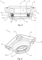
- the flanged element 2 of the first support 1 may have, for example, a circular shape.
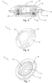
- the flanged element 2' of the second support 1' may have, for example, a square shape, as shown in Figure 9 . It will be understood that the flanged elements 2 and 2' may have any other shape.
- first seat 11 and a second seat 11' which extend along the axis X, respectively.
- first seat 11 which is defined in the flanged element 2 of the first support 1 is blind and is configured to receive the first end 104 of the blade-carrying shaft 101 at the side of the first support 1 which is directed towards the box-shaped beam 102, as shown in Figures 4 to 7 .
- the second rolling track 6 is structurally integrated with the respective flanged element so as to define therewith, and furthermore with the bearing ring 3 and the rolling elements 4, a rolling bearing which is integrated in the same flanged element.
- This solution allows the use of rolling elements 4 with greater dimensions than those used in a conventional tool-carrying group as described above with reference to the prior art without this further involving a greater spatial requirement of the group itself.
- the bearing ring 3 can be disassembled into two halves. Therefore, the flanged element 2 of the first support 1 with the spheres 4 and relevant cage 41 can be mounted independently of the two halves of the bearing ring 3.
- the flanged elements 2, 2' of the supports 1, 1' and/or the rings 3 and/or the rolling elements 4 are made from steel or another metal material having mechanical properties which are adequate for ensuring secure and durable operation of the tool-carrying group 1.
- the sealing element 7 may be of the type of a cassette seal comprising a plurality of sealing lips 70 which are interposed between an external sealing ring 71 and an internal sealing ring 72.
- the external sealing ring 71 is received in an annular seat 73 of the collar 113 while the internal sealing ring 72 engages in a sealing manner on the blade-carrying shaft 101.
- the rings 71, 72 are rigid sealing elements, between which there are interposed the sealing lips 70 which are made from resilient material, such as, for example, an elastomer material.
- the cassette seal further comprises a toroidal spring 74.
- the sealing lips 70 inside the cassette seal form a greased serpentine arrangement. Filling with grease reduces the wear, thereby extending the maintenance intervals.
- the invention thereby solves the problem set out while achieving a number of advantages, including:
Landscapes
- Life Sciences & Earth Sciences (AREA)
- Engineering & Computer Science (AREA)
- Mechanical Engineering (AREA)
- Soil Sciences (AREA)
- Environmental Sciences (AREA)
- Power Engineering (AREA)
- Rolling Contact Bearings (AREA)
Priority Applications (1)
| Application Number | Priority Date | Filing Date | Title |
|---|---|---|---|
| RS20250694A RS67048B1 (sr) | 2020-11-09 | 2021-11-09 | Grupa za nošenje alata za poljoprivredne mašine |
Applications Claiming Priority (3)
| Application Number | Priority Date | Filing Date | Title |
|---|---|---|---|
| IT202020000006245U IT202000006245U1 (it) | 2020-11-09 | 2020-11-09 | Gruppo portautensili per macchine agricole |
| IT202000026672 | 2020-11-09 | ||
| PCT/IB2021/060346 WO2022097116A1 (en) | 2020-11-09 | 2021-11-09 | Tool-carrying group for agricultural machines |
Publications (2)
| Publication Number | Publication Date |
|---|---|
| EP4240133A1 EP4240133A1 (en) | 2023-09-13 |
| EP4240133B1 true EP4240133B1 (en) | 2025-04-16 |
Family
ID=78770830
Family Applications (1)
| Application Number | Title | Priority Date | Filing Date |
|---|---|---|---|
| EP21814880.7A Active EP4240133B1 (en) | 2020-11-09 | 2021-11-09 | Tool-carrying group for agricultural machines |
Country Status (6)
| Country | Link |
|---|---|
| EP (1) | EP4240133B1 (pl) |
| CN (1) | CN116471925B (pl) |
| ES (1) | ES3036169T3 (pl) |
| PL (1) | PL4240133T3 (pl) |
| RS (1) | RS67048B1 (pl) |
| WO (1) | WO2022097116A1 (pl) |
Families Citing this family (1)
| Publication number | Priority date | Publication date | Assignee | Title |
|---|---|---|---|---|
| EP4376584B1 (en) * | 2021-07-30 | 2025-04-23 | Maschio Gaspardo S.p.A. | Agricultural machine |
Family Cites Families (16)
| Publication number | Priority date | Publication date | Assignee | Title |
|---|---|---|---|---|
| NL7408245A (nl) * | 1974-06-20 | 1975-12-23 | Lely Nv C Van Der | Grondbewerkingsmachine. |
| DE3916267A1 (de) * | 1989-05-19 | 1990-12-06 | Niemeyer Gmbh & Co Kg Soehne | Zapfwellenangetriebene kreiselegge |
| DE19842145A1 (de) * | 1998-09-15 | 2000-03-16 | Mannesmann Rexroth Ag | Abstützung für einen Wagenkasten an einem Fahrgestell |
| IT251483Y1 (it) * | 2000-07-07 | 2003-11-19 | Valex Internat Sa | Struttura rotante di supporto del gruppo utensili in un rastrello motorizzato, e rastrello motorizzato relativo |
| CN101046225A (zh) * | 2002-07-15 | 2007-10-03 | 日本精工株式会社 | 车轮支撑用滚动轴承单元 |
| DE102006007580A1 (de) * | 2006-02-18 | 2007-09-06 | Schaeffler Kg | Rotierendes landwirtschaftliches Werkzeug mit Lageranordnung |
| JP4894652B2 (ja) * | 2007-06-25 | 2012-03-14 | 日本精工株式会社 | 車輪支持用転がり軸受ユニットの製造方法 |
| ITPD20090018U1 (it) * | 2009-03-26 | 2010-09-27 | Maschio Gaspardo Spa | Erpice rotativo perfezionato |
| IT1401699B1 (it) * | 2010-09-13 | 2013-08-02 | Feraboli S P A | Gruppo falciante a dischi, particolarmente per macchine agricole del tipo falciatrici, falciacondizionatrici o simili, ad elevata sicurezza di impiego. |
| DE102012207749A1 (de) * | 2012-05-09 | 2013-11-14 | Schaeffler Technologies AG & Co. KG | Lageranordnung sowie Parabolrinnenkollektor |
| KR102064046B1 (ko) * | 2015-02-09 | 2020-01-08 | 광씨 우펑 머시너리 컴퍼니 리미티드 | 확장형 경운 리지분쇄기 및 경운 리지분쇄기 |
| DE102016222795A1 (de) * | 2016-11-18 | 2018-05-24 | Thyssenkrupp Ag | Lenkwelle für ein Kraftfahrzeug |
| DE102017108558A1 (de) * | 2017-04-21 | 2018-10-25 | Beckhoff Automation Gmbh | Fördereinrichtung und Lineartransportsystem |
| CN207235374U (zh) * | 2017-09-20 | 2018-04-17 | 兰州工业学院 | 一种新型的农用翻土装置 |
| DE102017223599A1 (de) * | 2017-12-21 | 2019-07-18 | Zf Friedrichshafen Ag | Fahrzeugachse für eine selbstfahrende Arbeitsmaschine sowie Arbeitsmaschine mit der Fahrzeugachse |
| CN211210384U (zh) * | 2019-11-29 | 2020-08-11 | 新疆中收农牧机械有限公司 | 一种被动轴及座一体的动力驱动耙 |
-
2021
- 2021-11-09 PL PL21814880.7T patent/PL4240133T3/pl unknown
- 2021-11-09 CN CN202180075312.7A patent/CN116471925B/zh active Active
- 2021-11-09 ES ES21814880T patent/ES3036169T3/es active Active
- 2021-11-09 RS RS20250694A patent/RS67048B1/sr unknown
- 2021-11-09 WO PCT/IB2021/060346 patent/WO2022097116A1/en not_active Ceased
- 2021-11-09 EP EP21814880.7A patent/EP4240133B1/en active Active
Also Published As
| Publication number | Publication date |
|---|---|
| EP4240133A1 (en) | 2023-09-13 |
| WO2022097116A1 (en) | 2022-05-12 |
| CN116471925B (zh) | 2025-12-12 |
| PL4240133T3 (pl) | 2025-08-25 |
| RS67048B1 (sr) | 2025-08-29 |
| ES3036169T3 (en) | 2025-09-15 |
| CN116471925A (zh) | 2023-07-21 |
Similar Documents
| Publication | Publication Date | Title |
|---|---|---|
| US4757211A (en) | Machine for generating electricity | |
| EP2238346B1 (en) | Epicyclic gear stage for a wind turbine gearbox, a wind turbine gearbox and a wind turbine | |
| US20090285693A1 (en) | Wind Turbine, A Method For Servicing A Main Bearing Unit Of A Wind Turbine And Use Thereof | |
| EP4240133B1 (en) | Tool-carrying group for agricultural machines | |
| EP2296959A2 (en) | Self-lubricated track roller assembly and machine using same | |
| US3819243A (en) | Bearing unit for a rotating drum | |
| EP2655879B1 (de) | Windkraftanlage | |
| US3713494A (en) | Alternative input drives on housing of gearbox for tools rotating about vertical axes | |
| US6293631B1 (en) | Crawler sprocket drive guard | |
| RU2654113C1 (ru) | Комплект стоечно-корпусных редукционных приводов со сменными дисками с вращающимися лопастями "ВИКОСТ" | |
| WO2000035585A1 (en) | A mineral breaker | |
| US5167590A (en) | Gearbox, preferably a cycloidal one, for direct connection with a driving and driven element | |
| CA3064543A1 (en) | Compound harmonic gearbox configured for continuous output rotation | |
| RU2659391C1 (ru) | Комплект почвенных орудий к боронам и культиваторам с редукционными приводами с вращающимися лопастями "викост" | |
| CN114787451B (zh) | 具有分离式内轮/集成轴承的沟槽切割机驱动器 | |
| HUE035060T2 (hu) | Gyûrûkerék és henger talajmûveléshez | |
| DE102014205816A1 (de) | Lageranordnung zur drehbaren Lagerung eines Turbinenblattes an einer Turbinennabe | |
| IT202000006245U1 (it) | Gruppo portautensili per macchine agricole | |
| US20140145410A1 (en) | Bearing assembly for oscillation joint | |
| JP6941861B2 (ja) | 農作業機 | |
| US4396236A (en) | Bearing unit | |
| RU2163431C1 (ru) | Машина для добычи лакричного сырья | |
| US11959457B2 (en) | Series of planetary gearboxes, wind turbine, industrial application, and use of rolling bearings | |
| RU235348U1 (ru) | Культиватор дисковый для ухода за лесными культурами | |
| RU237623U1 (ru) | Культиватор дисковый навесной для ухода за лесными культурами |
Legal Events
| Date | Code | Title | Description |
|---|---|---|---|
| STAA | Information on the status of an ep patent application or granted ep patent |
Free format text: STATUS: UNKNOWN |
|
| STAA | Information on the status of an ep patent application or granted ep patent |
Free format text: STATUS: THE INTERNATIONAL PUBLICATION HAS BEEN MADE |
|
| PUAI | Public reference made under article 153(3) epc to a published international application that has entered the european phase |
Free format text: ORIGINAL CODE: 0009012 |
|
| STAA | Information on the status of an ep patent application or granted ep patent |
Free format text: STATUS: REQUEST FOR EXAMINATION WAS MADE |
|
| 17P | Request for examination filed |
Effective date: 20230421 |
|
| AK | Designated contracting states |
Kind code of ref document: A1 Designated state(s): AL AT BE BG CH CY CZ DE DK EE ES FI FR GB GR HR HU IE IS IT LI LT LU LV MC MK MT NL NO PL PT RO RS SE SI SK SM TR |
|
| P01 | Opt-out of the competence of the unified patent court (upc) registered |
Effective date: 20231002 |
|
| DAV | Request for validation of the european patent (deleted) | ||
| DAX | Request for extension of the european patent (deleted) | ||
| GRAP | Despatch of communication of intention to grant a patent |
Free format text: ORIGINAL CODE: EPIDOSNIGR1 |
|
| STAA | Information on the status of an ep patent application or granted ep patent |
Free format text: STATUS: GRANT OF PATENT IS INTENDED |
|
| RIC1 | Information provided on ipc code assigned before grant |
Ipc: A01B 21/06 20060101ALN20241129BHEP Ipc: A01B 23/04 20060101ALI20241129BHEP Ipc: A01B 33/06 20060101ALI20241129BHEP Ipc: A01B 33/08 20060101AFI20241129BHEP |
|
| INTG | Intention to grant announced |
Effective date: 20241219 |
|
| GRAS | Grant fee paid |
Free format text: ORIGINAL CODE: EPIDOSNIGR3 |
|
| GRAA | (expected) grant |
Free format text: ORIGINAL CODE: 0009210 |
|
| STAA | Information on the status of an ep patent application or granted ep patent |
Free format text: STATUS: THE PATENT HAS BEEN GRANTED |
|
| AK | Designated contracting states |
Kind code of ref document: B1 Designated state(s): AL AT BE BG CH CY CZ DE DK EE ES FI FR GB GR HR HU IE IS IT LI LT LU LV MC MK MT NL NO PL PT RO RS SE SI SK SM TR |
|
| REG | Reference to a national code |
Ref country code: GB Ref legal event code: FG4D |
|
| REG | Reference to a national code |
Ref country code: CH Ref legal event code: EP |
|
| REG | Reference to a national code |
Ref country code: IE Ref legal event code: FG4D |
|
| REG | Reference to a national code |
Ref country code: DE Ref legal event code: R096 Ref document number: 602021029332 Country of ref document: DE |
|
| REG | Reference to a national code |
Ref country code: NL Ref legal event code: MP Effective date: 20250416 |
|
| PG25 | Lapsed in a contracting state [announced via postgrant information from national office to epo] |
Ref country code: NL Free format text: LAPSE BECAUSE OF FAILURE TO SUBMIT A TRANSLATION OF THE DESCRIPTION OR TO PAY THE FEE WITHIN THE PRESCRIBED TIME-LIMIT Effective date: 20250416 |
|
| REG | Reference to a national code |
Ref country code: ES Ref legal event code: FG2A Ref document number: 3036169 Country of ref document: ES Kind code of ref document: T3 Effective date: 20250915 |
|
| PG25 | Lapsed in a contracting state [announced via postgrant information from national office to epo] |
Ref country code: FI Free format text: LAPSE BECAUSE OF FAILURE TO SUBMIT A TRANSLATION OF THE DESCRIPTION OR TO PAY THE FEE WITHIN THE PRESCRIBED TIME-LIMIT Effective date: 20250416 Ref country code: PT Free format text: LAPSE BECAUSE OF FAILURE TO SUBMIT A TRANSLATION OF THE DESCRIPTION OR TO PAY THE FEE WITHIN THE PRESCRIBED TIME-LIMIT Effective date: 20250818 |
|
| REG | Reference to a national code |
Ref country code: LT Ref legal event code: MG9D |
|
| PG25 | Lapsed in a contracting state [announced via postgrant information from national office to epo] |
Ref country code: NO Free format text: LAPSE BECAUSE OF FAILURE TO SUBMIT A TRANSLATION OF THE DESCRIPTION OR TO PAY THE FEE WITHIN THE PRESCRIBED TIME-LIMIT Effective date: 20250716 Ref country code: GR Free format text: LAPSE BECAUSE OF FAILURE TO SUBMIT A TRANSLATION OF THE DESCRIPTION OR TO PAY THE FEE WITHIN THE PRESCRIBED TIME-LIMIT Effective date: 20250717 |
|
| PG25 | Lapsed in a contracting state [announced via postgrant information from national office to epo] |
Ref country code: BG Free format text: LAPSE BECAUSE OF FAILURE TO SUBMIT A TRANSLATION OF THE DESCRIPTION OR TO PAY THE FEE WITHIN THE PRESCRIBED TIME-LIMIT Effective date: 20250416 |
|
| PG25 | Lapsed in a contracting state [announced via postgrant information from national office to epo] |
Ref country code: HR Free format text: LAPSE BECAUSE OF FAILURE TO SUBMIT A TRANSLATION OF THE DESCRIPTION OR TO PAY THE FEE WITHIN THE PRESCRIBED TIME-LIMIT Effective date: 20250416 |
|
| PG25 | Lapsed in a contracting state [announced via postgrant information from national office to epo] |
Ref country code: IS Free format text: LAPSE BECAUSE OF FAILURE TO SUBMIT A TRANSLATION OF THE DESCRIPTION OR TO PAY THE FEE WITHIN THE PRESCRIBED TIME-LIMIT Effective date: 20250816 |
|
| PG25 | Lapsed in a contracting state [announced via postgrant information from national office to epo] |
Ref country code: LV Free format text: LAPSE BECAUSE OF FAILURE TO SUBMIT A TRANSLATION OF THE DESCRIPTION OR TO PAY THE FEE WITHIN THE PRESCRIBED TIME-LIMIT Effective date: 20250416 |
|
| PGFP | Annual fee paid to national office [announced via postgrant information from national office to epo] |
Ref country code: DE Payment date: 20251119 Year of fee payment: 5 |
|
| PGFP | Annual fee paid to national office [announced via postgrant information from national office to epo] |
Ref country code: GB Payment date: 20251121 Year of fee payment: 5 |
|
| PG25 | Lapsed in a contracting state [announced via postgrant information from national office to epo] |
Ref country code: DK Free format text: LAPSE BECAUSE OF FAILURE TO SUBMIT A TRANSLATION OF THE DESCRIPTION OR TO PAY THE FEE WITHIN THE PRESCRIBED TIME-LIMIT Effective date: 20250416 Ref country code: SM Free format text: LAPSE BECAUSE OF FAILURE TO SUBMIT A TRANSLATION OF THE DESCRIPTION OR TO PAY THE FEE WITHIN THE PRESCRIBED TIME-LIMIT Effective date: 20250416 |
|
| PGFP | Annual fee paid to national office [announced via postgrant information from national office to epo] |
Ref country code: AT Payment date: 20260113 Year of fee payment: 5 |
|
| PGFP | Annual fee paid to national office [announced via postgrant information from national office to epo] |
Ref country code: IT Payment date: 20251016 Year of fee payment: 5 |
|
| PGFP | Annual fee paid to national office [announced via postgrant information from national office to epo] |
Ref country code: FR Payment date: 20251126 Year of fee payment: 5 |
|
| PGFP | Annual fee paid to national office [announced via postgrant information from national office to epo] |
Ref country code: BE Payment date: 20251119 Year of fee payment: 5 |
|
| PG25 | Lapsed in a contracting state [announced via postgrant information from national office to epo] |
Ref country code: CZ Free format text: LAPSE BECAUSE OF FAILURE TO SUBMIT A TRANSLATION OF THE DESCRIPTION OR TO PAY THE FEE WITHIN THE PRESCRIBED TIME-LIMIT Effective date: 20250416 |
|
| PGFP | Annual fee paid to national office [announced via postgrant information from national office to epo] |
Ref country code: PL Payment date: 20251030 Year of fee payment: 5 |
|
| PG25 | Lapsed in a contracting state [announced via postgrant information from national office to epo] |
Ref country code: EE Free format text: LAPSE BECAUSE OF FAILURE TO SUBMIT A TRANSLATION OF THE DESCRIPTION OR TO PAY THE FEE WITHIN THE PRESCRIBED TIME-LIMIT Effective date: 20250416 |
|
| PG25 | Lapsed in a contracting state [announced via postgrant information from national office to epo] |
Ref country code: SK Free format text: LAPSE BECAUSE OF FAILURE TO SUBMIT A TRANSLATION OF THE DESCRIPTION OR TO PAY THE FEE WITHIN THE PRESCRIBED TIME-LIMIT Effective date: 20250416 |
|
| PGFP | Annual fee paid to national office [announced via postgrant information from national office to epo] |
Ref country code: RS Payment date: 20251031 Year of fee payment: 5 |
|
| PGFP | Annual fee paid to national office [announced via postgrant information from national office to epo] |
Ref country code: ES Payment date: 20251229 Year of fee payment: 5 |