EP2655879B1 - Windkraftanlage - Google Patents
Windkraftanlage Download PDFInfo
- Publication number
- EP2655879B1 EP2655879B1 EP11797243.0A EP11797243A EP2655879B1 EP 2655879 B1 EP2655879 B1 EP 2655879B1 EP 11797243 A EP11797243 A EP 11797243A EP 2655879 B1 EP2655879 B1 EP 2655879B1
- Authority
- EP
- European Patent Office
- Prior art keywords
- bearing
- pinion
- inner ring
- generator
- rotor
- Prior art date
- Legal status (The legal status is an assumption and is not a legal conclusion. Google has not performed a legal analysis and makes no representation as to the accuracy of the status listed.)
- Active
Links
Images

Classifications
-
- F—MECHANICAL ENGINEERING; LIGHTING; HEATING; WEAPONS; BLASTING
- F16—ENGINEERING ELEMENTS AND UNITS; GENERAL MEASURES FOR PRODUCING AND MAINTAINING EFFECTIVE FUNCTIONING OF MACHINES OR INSTALLATIONS; THERMAL INSULATION IN GENERAL
- F16H—GEARING
- F16H1/00—Toothed gearings for conveying rotary motion
- F16H1/02—Toothed gearings for conveying rotary motion without gears having orbital motion
- F16H1/20—Toothed gearings for conveying rotary motion without gears having orbital motion involving more than two intermeshing members
- F16H1/22—Toothed gearings for conveying rotary motion without gears having orbital motion involving more than two intermeshing members with a plurality of driving or driven shafts; with arrangements for dividing torque between two or more intermediate shafts
- F16H1/227—Toothed gearings for conveying rotary motion without gears having orbital motion involving more than two intermeshing members with a plurality of driving or driven shafts; with arrangements for dividing torque between two or more intermediate shafts comprising two or more gearwheels in mesh with the same internally toothed wheel
-
- F—MECHANICAL ENGINEERING; LIGHTING; HEATING; WEAPONS; BLASTING
- F03—MACHINES OR ENGINES FOR LIQUIDS; WIND, SPRING, OR WEIGHT MOTORS; PRODUCING MECHANICAL POWER OR A REACTIVE PROPULSIVE THRUST, NOT OTHERWISE PROVIDED FOR
- F03D—WIND MOTORS
- F03D80/00—Details, components or accessories not provided for in groups F03D1/00 - F03D17/00
- F03D80/70—Bearing or lubricating arrangements
-
- F—MECHANICAL ENGINEERING; LIGHTING; HEATING; WEAPONS; BLASTING
- F05—INDEXING SCHEMES RELATING TO ENGINES OR PUMPS IN VARIOUS SUBCLASSES OF CLASSES F01-F04
- F05B—INDEXING SCHEME RELATING TO WIND, SPRING, WEIGHT, INERTIA OR LIKE MOTORS, TO MACHINES OR ENGINES FOR LIQUIDS COVERED BY SUBCLASSES F03B, F03D AND F03G
- F05B2260/00—Function
- F05B2260/70—Adjusting of angle of incidence or attack of rotating blades
- F05B2260/79—Bearing, support or actuation arrangements therefor
-
- F—MECHANICAL ENGINEERING; LIGHTING; HEATING; WEAPONS; BLASTING
- F16—ENGINEERING ELEMENTS AND UNITS; GENERAL MEASURES FOR PRODUCING AND MAINTAINING EFFECTIVE FUNCTIONING OF MACHINES OR INSTALLATIONS; THERMAL INSULATION IN GENERAL
- F16C—SHAFTS; FLEXIBLE SHAFTS; ELEMENTS OR CRANKSHAFT MECHANISMS; ROTARY BODIES OTHER THAN GEARING ELEMENTS; BEARINGS
- F16C17/00—Sliding-contact bearings for exclusively rotary movement
-
- F—MECHANICAL ENGINEERING; LIGHTING; HEATING; WEAPONS; BLASTING
- F16—ENGINEERING ELEMENTS AND UNITS; GENERAL MEASURES FOR PRODUCING AND MAINTAINING EFFECTIVE FUNCTIONING OF MACHINES OR INSTALLATIONS; THERMAL INSULATION IN GENERAL
- F16C—SHAFTS; FLEXIBLE SHAFTS; ELEMENTS OR CRANKSHAFT MECHANISMS; ROTARY BODIES OTHER THAN GEARING ELEMENTS; BEARINGS
- F16C19/00—Bearings with rolling contact, for exclusively rotary movement
- F16C19/22—Bearings with rolling contact, for exclusively rotary movement with bearing rollers essentially of the same size in one or more circular rows, e.g. needle bearings
- F16C19/34—Bearings with rolling contact, for exclusively rotary movement with bearing rollers essentially of the same size in one or more circular rows, e.g. needle bearings for both radial and axial load
- F16C19/38—Bearings with rolling contact, for exclusively rotary movement with bearing rollers essentially of the same size in one or more circular rows, e.g. needle bearings for both radial and axial load with two or more rows of rollers
- F16C19/383—Bearings with rolling contact, for exclusively rotary movement with bearing rollers essentially of the same size in one or more circular rows, e.g. needle bearings for both radial and axial load with two or more rows of rollers with tapered rollers, i.e. rollers having essentially the shape of a truncated cone
- F16C19/385—Bearings with rolling contact, for exclusively rotary movement with bearing rollers essentially of the same size in one or more circular rows, e.g. needle bearings for both radial and axial load with two or more rows of rollers with tapered rollers, i.e. rollers having essentially the shape of a truncated cone with two rows, i.e. double-row tapered roller bearings
-
- F—MECHANICAL ENGINEERING; LIGHTING; HEATING; WEAPONS; BLASTING
- F16—ENGINEERING ELEMENTS AND UNITS; GENERAL MEASURES FOR PRODUCING AND MAINTAINING EFFECTIVE FUNCTIONING OF MACHINES OR INSTALLATIONS; THERMAL INSULATION IN GENERAL
- F16C—SHAFTS; FLEXIBLE SHAFTS; ELEMENTS OR CRANKSHAFT MECHANISMS; ROTARY BODIES OTHER THAN GEARING ELEMENTS; BEARINGS
- F16C2360/00—Engines or pumps
- F16C2360/31—Wind motors
-
- F—MECHANICAL ENGINEERING; LIGHTING; HEATING; WEAPONS; BLASTING
- F16—ENGINEERING ELEMENTS AND UNITS; GENERAL MEASURES FOR PRODUCING AND MAINTAINING EFFECTIVE FUNCTIONING OF MACHINES OR INSTALLATIONS; THERMAL INSULATION IN GENERAL
- F16C—SHAFTS; FLEXIBLE SHAFTS; ELEMENTS OR CRANKSHAFT MECHANISMS; ROTARY BODIES OTHER THAN GEARING ELEMENTS; BEARINGS
- F16C32/00—Bearings not otherwise provided for
- F16C32/06—Bearings not otherwise provided for with moving member supported by a fluid cushion formed, at least to a large extent, otherwise than by movement of the shaft, e.g. hydrostatic air-cushion bearings
-
- F—MECHANICAL ENGINEERING; LIGHTING; HEATING; WEAPONS; BLASTING
- F16—ENGINEERING ELEMENTS AND UNITS; GENERAL MEASURES FOR PRODUCING AND MAINTAINING EFFECTIVE FUNCTIONING OF MACHINES OR INSTALLATIONS; THERMAL INSULATION IN GENERAL
- F16C—SHAFTS; FLEXIBLE SHAFTS; ELEMENTS OR CRANKSHAFT MECHANISMS; ROTARY BODIES OTHER THAN GEARING ELEMENTS; BEARINGS
- F16C33/00—Parts of bearings; Special methods for making bearings or parts thereof
- F16C33/30—Parts of ball or roller bearings
- F16C33/58—Raceways; Race rings
- F16C33/581—Raceways; Race rings integral with other parts, e.g. with housings or machine elements such as shafts or gear wheels
-
- Y—GENERAL TAGGING OF NEW TECHNOLOGICAL DEVELOPMENTS; GENERAL TAGGING OF CROSS-SECTIONAL TECHNOLOGIES SPANNING OVER SEVERAL SECTIONS OF THE IPC; TECHNICAL SUBJECTS COVERED BY FORMER USPC CROSS-REFERENCE ART COLLECTIONS [XRACs] AND DIGESTS
- Y02—TECHNOLOGIES OR APPLICATIONS FOR MITIGATION OR ADAPTATION AGAINST CLIMATE CHANGE
- Y02E—REDUCTION OF GREENHOUSE GAS [GHG] EMISSIONS, RELATED TO ENERGY GENERATION, TRANSMISSION OR DISTRIBUTION
- Y02E10/00—Energy generation through renewable energy sources
- Y02E10/70—Wind energy
- Y02E10/72—Wind turbines with rotation axis in wind direction
Definitions
- the invention relates to a wind turbine, comprising a housing, a rotor and at least one generator shaft having a generator, wherein the rotor is mounted relative to the housing in a bearing assembly having at least two bearing rings and wherein between the rotor and the generator, a drive train is arranged to transmit the rotation of the rotor to the at least one generator shaft, wherein the drive train comprises the at least one bearing inner ring of the bearing assembly, wherein the rotor is flanged to an end face of the bearing inner ring and thus rotatably connected to the bearing inner ring, wherein the bearing inner ring with a on the inner circumference of the bearing inner ring (ie on a cylindrical inner surface of the bearing inner race) arranged toothing is provided, wherein the drive train further comprises at least one pinion, which is in engagement with the toothing of the bearing inner ring, wherein the pinion directly or via a transmission with the Genera Torwelle is connected and wherein the pinion is arranged radially inside the bearing inner ring
- Wind turbines of this type are well known in the art.
- a plant of the generic type shows the DE 10 2007 041 508 A1 .
- Similar solution show the DE 10 2007 008 758 A1 , the DE 10 2006 057 055 B3 , the DE 103 51 524 A1 , the DE 10 2007 042 770 A1 , the EP 1 677 005 A1 and the DE 103 51 524 A1 .
- the rotor of the system is stored in a large warehouse, often a double row tapered roller bearing assembly is used.
- the so-mounted rotor is often coupled via a gearbox with the generator shaft, so that its rotation is transmitted to the generator shaft. This is how electrical energy can be gained.
- the invention is therefore based on the object, a wind turbine of the generic type train so that a simpler, cheaper and more flexible concept is given.
- the availability of the system should be increased.
- the solution of this problem by the invention is characterized in that the pinion together with the generator shaft, possibly existing gear and generator are arranged eccentrically to the axis of rotation of the rotor.
- the drive train preferably has at least two pinions, each of which is in engagement with the toothing, wherein each pinion is connected directly or via a transmission with a generator shaft of a generator.
- the drive train has according to a particularly preferred embodiment, at least 3 to 6 pinions, which are respectively engaged with the toothing, each pinion is connected directly or via a gear to a generator shaft of a generator and wherein the pinion preferably evenly distributed around the circumference of the inner ring are arranged.
- the pinion together with direct or indirect connection to the generator shaft and the generator are preferably designed as a replaceable unit.
- each generator together with connection via the pinion is a module (one unit), if necessary, in or out Intervention with the toothed bearing ring can be brought.
- This offers in particular the possibility to continue to run the wind turbine in case of failure of a generator and only to replace the failed generator.
- the bearing arrangement is preferably designed as a roller bearing assembly. This is especially thought of a double-row tapered roller bearing assembly. This can be according to a training, the only storage of the rotor, the two tapered roller bearings are arranged in an X-arrangement.
- the bearing arrangement may also be designed differently, with a possible solution being based on a hydrostatic bearing.
- the advantage of the proposed solution is first that no large generator is more mandatory, but that a number of smaller generators can be used.
- the individual generators can be changed quickly by interchangeability.
- Another advantage is that in the event that there is a lower wind speed, only a part of the generators can be connected to the grid, so that even then electricity can be generated.
- the proposed concept is characterized by a significantly increased flexibility, which can also be implemented inexpensively.
- a wind turbine 1 is shown, which is constructed in a conventional manner. It has a housing 2, in which the storage for the (main) rotor 3 is housed; furthermore, here is the in Fig. 1 not shown generator arranged.
- the bearing assembly 8 generally has at least one bearing outer ring 6 and at least one bearing inner ring 7.
- the bearing assembly 8 is designed here as a rolling bearing, as a double-row tapered roller bearings. Accordingly, two outer bearing rings 6 'and 6 "are arranged adjacently, tapered rollers provide the rolling connection to a bearing inner ring 7', 7" which, in the exemplary embodiment, has two raceways as a one-piece bearing ring.
- the rotor 3 of the wind turbine 1 is directly flanged to an end face 10 of the bearing inner ring 7 ', d. H. the rotor 3 rests with an axial end surface on the end face 10 of the bearing inner ring 7 'and is here fixed with screws on the bearing inner ring 7'.
- the bearing inner ring 7 ' corresponding threaded holes.
- the bearing inner ring 7 ', 7 "on its cylindrical inner peripheral surface has a toothing 11.
- mesh pinion 12 of which several are distributed around the circumference of the bearing inner ring 7', 7", but only one of which is shown ,
- the bearing inner ring 7, 7 "and the pinion 12 are part of a drive train 9, with which the rotation of the rotor 3 is transmitted to the generator shafts 4 of the generators 5, of which one of the number of pinions 12 corresponding number is available.
- the pinions 12 are directly or indirectly - in the embodiment via a gear 13 - rotatably connected to the generator shafts 4.
- the elements pinion 12, optionally gear 13, generator shaft 4 and generator 5 are formed as a unit. Accordingly, a unit can be assembled as a complete module and then the pinion 12 can be engaged with the gearing 11 to activate the unit.
- the bearing assembly 8 can also be arbitrarily different than in Fig. 2 be shown represented. In this case, in addition to rolling bearings and bearings or - according to a specific preferred embodiment - also hydrostatic bearings are used.
- seals for storage, etc. can be provided in an expert manner complementary.
- the rotor bearing 8 can thus be designed as a rolling or sliding bearing for the absorption of radial and axial forces and moments.
- a double row tapered roller bearing is provided in an X-arrangement.
- the bearing rings are each flange-mounted and sealed on both sides.
- the toothing 11 is preferably an integral part of the bearing ring. In this case, the toothing 11 but not only be formed from the material of the bearing ring, but for example pressed as a separate component, shrunk or screwed and so connected to the bearing ring.
- the housing 2 is formed in the embodiment as a (non-rotating) frame construction. As in Fig. 2 can be seen that the generator 5 as the transmission 13th formed flanged element, wherein the transmission 13 is in turn flanged to the housing 2.
- the flange solution of the bearing rings is preferred, but not mandatory.
- the bearing rings can also sit classically on a shaft or in a housing.
Landscapes
- Engineering & Computer Science (AREA)
- General Engineering & Computer Science (AREA)
- Mechanical Engineering (AREA)
- Life Sciences & Earth Sciences (AREA)
- Sustainable Development (AREA)
- Sustainable Energy (AREA)
- Chemical & Material Sciences (AREA)
- Combustion & Propulsion (AREA)
- Wind Motors (AREA)
- Rolling Contact Bearings (AREA)
Description
- Die Erfindung betrifft eine Windkraftanlage, umfassend ein Gehäuse, einen Rotor und mindestens einen eine Generatorwelle aufweisenden Generator, wobei der Rotor relativ zu dem Gehäuse in einer mindestens zwei Lagerringe aufweisenden Lageranordnung gelagert ist und wobei zwischen dem Rotor und dem Generator ein Antriebsstrang angeordnet ist, um die Drehung des Rotors auf die mindestens eine Generatorwelle zu übertragen, wobei der Antriebsstrang den mindestens einen Lagerinnenring der Lageranordnung umfasst, wobei der Rotor an einer Stirnseite des Lagerinnenrings angeflanscht und so mit dem Lagerinnenring drehfest verbunden ist, wobei der Lagerinnenring mit einer am Innenumfang des Lagerinnenrings (d. h. an einer zylindrischen Innenfläche des Lagerinnenrings) angeordneten Verzahnung versehen ist, wobei der Antriebsstrang weiterhin mindestens ein Ritzel umfasst, das mit der Verzahnung des Lagerinnenrings in Eingriff steht, wobei das Ritzel direkt oder über ein Getriebe mit der Generatorwelle verbunden ist und wobei das Ritzel radial innerhalb des Lagerinnenrings angeordnet ist und wobei die Verzahnung und das Ritzel eine Stirnverzahnung bilden (d. h. die Achsen der miteinander kämmenden Zahnräder sind parallel zueinander angeordnet).
- Windkraftanlagen dieser Art sind im Stand der Technik hinlänglich bekannt. Eine Anlage der gattungsgemäßen Art zeigt die
DE 10 2007 041 508 A1 . Ähnliche Lösung zeigen dieDE 10 2007 008 758 A1 , dieDE 10 2006 057 055 B3 , dieDE 103 51 524 A1 , dieDE 10 2007 042 770 A1 , dieEP 1 677 005 A1 und dieDE 103 51 524 A1 . Der Rotor der Anlage wird in einem Großlager gelagert, wobei häufig eine zweireihige Kegelrollenlageranordnung zum Einsatz kommt. Der so gelagerte Rotor ist häufig über ein Getriebe mit der Generatorwelle gekoppelt, so dass seine Drehung auf die Generatorwelle übertragen wird. So kann elektrische Energie gewonnen werden. - Nachteilig ist bei den vorbekannten Lösungen, dass die Anlage aufgrund ihrer Dimensionen sehr groß und teuer ist. Dies gilt insbesondere für den Generator. Weiterhin bedeutet es bei der vorbekannten Konzeption, dass im Falle dessen, dass der Generator wartungs- bzw. reparaturbedingt ausfällt, die gesamte Anlage angehalten werden muss und bis zum Abschluss der Wartung- bzw. Reparaturarbeiten keine Energie erzeugt werden kann.
- Der Erfindung liegt daher die Aufgabe zu Grunde, eine Windkraftanlage der gattungsgemäßen Art so fortzubilden, dass ein einfacheres, kostengünstigeres und flexibleres Konzept gegeben ist. Die Verfügbarkeit der Anlage soll damit erhöht werden.
- Die Lösung dieser Aufgabe durch die Erfindung ist dadurch gekennzeichnet, dass das Ritzel samt Generatorwelle, gegebenenfalls vorhandenem Getriebe und Generator exzentrisch zur Drehachse des Rotors angeordnet sind.
- Der Antriebsstrang weist bevorzugt mindestens zwei Ritzel auf, die jeweils mit der Verzahnung in Eingriff stehen, wobei jedes Ritzel direkt oder über ein Getriebe mit einer Generatorwelle eines Generators verbunden ist.
- Der Antriebsstrang hat gemäß einer besonders bevorzugten Ausgestaltung mindestens 3 bis 6 Ritzel, die jeweils mit der Verzahnung in Eingriff stehen, wobei jedes Ritzel direkt oder über ein Getriebe mit einer Generatorwelle eines Generators verbunden ist und wobei die Ritzel bevorzugt gleichmäßig um den Umfang des Innenrings verteilt angeordnet sind.
- Das Ritzel samt direkter oder indirekter Verbindung zur Generatorwelle und der Generator sind dabei bevorzugt als auswechselbare Einheit ausgebildet.
- Dies eröffnet die Möglichkeit, dass eine Anzahl kleinerer Generatoren, und nicht mehr wie im Stand der Technik ein einziger großer Generator, zum Einsatz kommt, wobei jeder Generator samt Anbindung über das Ritzel ein Modul (eine Einheit) darstellt, die bei Bedarf in oder außer Eingriff mit dem verzahnten Lagerring gebracht werden kann. Dies bietet insbesondere die Möglichkeit, beim Ausfall eines Generators die Windkraftanlage weiterlaufen zu lassen und lediglich den ausgefallenen Generator zu ersetzen.
- Die Lageranordnung ist bevorzugt als Wälzlageranordnung ausgebildet. Hierbei ist insbesondere an eine zweireihige Kegelrollenlageranordnung gedacht. Diese kann gemäß einer Fortbildung die einzige Lagerung des Rotors sein, wobei die beiden Kegelrollenlager in X-Anordnung angeordnet sind.
- Die Lageranordnung kann auch andersartig ausgeführt sein, wobei eine mögliche Lösung auf eine hydrostatische Lagerung abstellt.
- Natürlich sind grundsätzlich auch andere Lageranordnungen möglich und denkbar.
- Der Vorteil der vorgeschlagenen Lösung besteht zunächst darin, dass kein großer Generator mehr zwingend ist, sondern dass auch eine Anzahl kleinerer Generatoren zum Einsatz kommen kann. Die einzelnen Generatoren können durch Austauschbarkeit schnell gewechselt werden.
- Ein weiterer Vorteil besteht darin, dass im Falle dessen, dass eine geringere Windgeschwindigkeit vorliegt, nur ein Teil der Generatoren ans Netz genommen werden kann, so dass auch dann Strom erzeugt werden kann.
- Demgemäß zeichnet sich die vorgeschlagene Konzeption durch eine wesentlich erhöhte Flexibilität aus, die auch kostengünstig umgesetzt werden kann.
- In der Zeichnung ist ein Ausführungsbeispiel der Erfindung dargestellt. Es zeigen:
- Fig. 1
- in perspektivscher Darstellung eine Windkraftanlage und
- Fig. 2
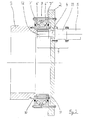
- einen Schnitt durch das Innere der Windkraftanlage.
- In
Fig. 1 ist eine Windkraftanlage 1 dargestellt, die in an sich bekannter Weise aufgebaut ist. Sie weist ein Gehäuse 2 auf, in dem die Lagerung für den (Haupt-)Rotor 3 untergebracht ist; ferner ist hier der inFig. 1 nicht dargestellte Generator angeordnet. Die Lageranordnung 8 weist generell mindestens einen Lageraußenring 6 und mindestens einen Lagerinnenring 7 auf. - In
Fig. 2 sind Details des Aufbaus der Anlage zu sehen. Die Lageranordnung 8 ist hier als Wälzlagerung ausgeführt, und zwar als zweireihige Kegelrollenlager. Demgemäß sind zwei Lageraußenringe 6' und 6" benachbart angeordnet. Kegelrollen stellen die Wälzverbindung zu einem Lagerinnenring 7', 7" her, der im Ausführungsbeispiel als einteiliger Lagerring zwei Laufbahnen aufweist. - Der Rotor 3 der Windkraftanlage 1 ist an einer Stirnseite 10 des Lagerinnenrings 7' direkt angeflanscht, d. h. der Rotor 3 liegt mit einer axialen Endfläche an der Stirnseite 10 des Lagerinnenrings 7' an und ist hier mit Schrauben am Lagerinnenring 7' fixiert. Hierzu weist der Lagerinnenring 7' entsprechende Gewindebohrungen auf.
- Weiterhin weist der Lagerinnenring 7', 7" an seiner zylindrischen Innenumfangsfläche eine Verzahnung 11 auf. Mit der Verzahnung 11 kämmen Ritzel 12, von denen mehrere um den Umfang des Lagerinnenrings 7', 7" verteilt angeordnet sind, von denen allerdings nur eines dargestellt ist.
- Der Lagerinnenring 7, 7" sowie die Ritzel 12 sind Bestandteil eines Antriebsstrangs 9, mit dem die Drehung des Rotors 3 auf die Generatorwellen 4 der Generatoren 5 übertragen wird, von denen eine der Anzahl der Ritzel 12 entsprechende Anzahl vorhanden ist. Die Ritzel 12 sind direkt oder indirekt - im Ausführungsbeispiel über ein Getriebe 13 - mit den Generatorwellen 4 drehfest verbunden.
- Zum Antrieb der Generatorwellen 4 werden die Ritzel 12 mit der Verzahnung 11 in Eingriff gebracht.
- Die Elemente Ritzel 12, gegebenenfalls Getriebe 13, Generatorwelle 4 und Generator 5 sind als Einheit ausgebildet. Demgemäß kann eine Einheit als komplettes Modul montiert und dann das Ritzel 12 mit der Verzahnung 11 in Eingriff gebracht werden, um die Einheit zu aktivieren.
- Die Lageranordnung 8 kann auch beliebig anders als in
Fig. 2 dargestellt ausgeführt sein. Dabei können neben Wälzlagern auch Gleitlager oder - gemäß einer speziellen bevorzugten Ausführungsform - auch hydrostatische Lagerungen verwendet werden. - Weitere Elemente, wie Dichtungen für die Lagerung etc., können in fachmännischer Weise ergänzend vorgesehen werden.
- Die Rotorlagerung 8 kann also als Wälz- oder Gleitlagerung für die Aufnahme von Radial- und Axialkräften sowie von Momenten ausgeführt sein. Im Ausführungsbeispiel ist eine zweireihige Kegelrollenlagerung in X-Anordnung vorgesehen. Die Lagerringe sind jeweils angeflanscht und beidseitig abgedichtet. Die Verzahnung 11 ist bevorzugt integrierter Bestandteil des Lagerrings. Dabei kann die Verzahnung 11 aber nicht nur aus dem Material des Lagerrings ausgeformt sein, sondern beispielsweise als separates Bauteil eingepresst, aufgeschrumpft oder angeschraubt und so mit dem Lagerring verbunden sein.
- Das Gehäuse 2 ist im Ausführungsbeispiel als (nicht drehende) Rahmenkonstruktion ausgebildet. Wie in
Fig. 2 zu sehen ist, die der Generator 5 als am Getriebe 13 angeflanschtes Element ausgebildet, wobei das Getriebe 13 wiederum am Gehäuse 2 angeflanscht ist. - Die Flanschlösung der Lagerringe ist bevorzugt, aber nicht zwingend. Die Lagerringe können auch klassisch auf einer Welle bzw. in einem Gehäuse sitzen.
- Sehr vorteilhaft ist die im Ausführungsbeispiel gemäß
Fig. 2 vorgesehene Ausgestaltung, wonach das Gehäuse 2 als Rahmenkonstruktion ausgebildet ist, d. h. im Wesentlichen eine Trägerplatte darstellt. Hier ergibt sich in vorteilhafter Weise, dass der Generator 5 samt Getriebe 13 an dem Gehäuse 2 angeflanscht werden kann, genauso wie dies für die Lageranordnung 8 selber gilt. Am Lagerinnenring 7 wiederum kann der Rotor 3 angeflanscht sein. Es ergibt sich somit ein modulares Konzept, das eine relativ einfache Montage erlaubt. Auch der Austausch von Generatoren 5 ist besonders einfach möglich. -
- 1
- Windkraftanlage
- 2
- Gehäuse
- 3
- Rotor
- 4
- Generatorwelle
- 5
- Generator
- 6, 7
- Lagerring
- 6, 6', 6"
- Lageraußenring
- 7, 7', 7"
- Lagerinnenring
- 8
- Lageranordnung
- 9
- Antriebsstrang
- 10
- Stirnseite
- 11
- Verzahnung
- 12
- Ritzel
- 13
- Getriebe
Claims (8)
- Windkraftanlage (1), umfassend ein Gehäuse (2), einen Rotor (3) und mindestens einen eine Generatorwelle (4) aufweisenden Generator (5), wobei der Rotor (3) relativ zu dem Gehäuse (2) in einer mindestens zwei Lagerringe (6, 6', 6", 7, 7', 7") aufweisenden Lageranordnung (8) gelagert ist und wobei zwischen dem Rotor (3) und dem Generator (5) ein Antriebsstrang (9) angeordnet ist, um die Drehung des Rotors (3) auf die mindestens eine Generatorwelle (4) zu übertragen, wobei der Antriebsstrang (9) den mindestens einen Lagerinnenring (7, 7', 7") der Lageranordnung (8) umfasst, wobei der Rotor (3) an einer Stirnseite (10) des Lagerinnenrings (7, 7', 7") angeflanscht und so mit dem Lagerinnenring (7, 7', 7") drehfest verbunden ist, wobei der Lagerinnenring (7, 7', 7") mit einer am Innenumfang des Lagerinnenrings (7, 7', 7") angeordneten Verzahnung (11) versehen ist, wobei der Antriebsstrang (9) weiterhin mindestens ein Ritzel (12) umfasst, das mit der Verzahnung (11) des Lagerinnenrings (7, 7', 7") in Eingriff steht, wobei das Ritzel (12) direkt oder über ein Getriebe (13) mit der Generatorwelle (4) verbunden ist und wobei das Ritzel (12) radial innerhalb des Lagerinnenrings (7, 7', 7") angeordnet ist und wobei die Verzahnung (11) und das Ritzel (12) eine Stirnverzahnung bilden,
dadurch gekennzeichnet,
dass das Ritzel (12) samt Generatorwelle (4), gegebenenfalls vorhandenem Getriebe (13) und Generator (5) exzentrisch zur Drehachse des Rotors (3) angeordnet sind. - Windkraftanlage nach Anspruch 1, dadurch gekennzeichnet, dass der Antriebsstrang (9) mindestens zwei Ritzel (12) aufweist, die jeweils mit der Verzahnung (11) in Eingriff stehen, wobei jedes Ritzel (12) direkt oder über ein Getriebe (13) mit einer Generatorwelle (4) verbunden ist.
- Windkraftanlage nach Anspruch 2, dadurch gekennzeichnet, dass der Antriebsstrang (9) mindestens 3 bis 6 Ritzel (12) aufweist, die jeweils mit der Verzahnung (11) in Eingriff stehen, wobei jedes Ritzel (12) direkt oder über ein Getriebe (13) mit einer Generatorwelle (4) verbunden ist und wobei die Ritzel (12) bevorzugt gleichmäßig um den Umfang des Innenrings (7, 7', 7") verteilt angeordnet sind.
- Windkraftanlage nach Anspruch 2 oder 3, dadurch gekennzeichnet, dass das Ritzel (12) samt direkter oder indirekter Verbindung zur Generatorwelle (4) und der Generator (5) als auswechselbare Einheit ausgebildet sind.
- Windkraftanlage nach einem der Ansprüche 1 bis 4, dadurch gekennzeichnet, dass die Lageranordnung (8) als Wälzlageranordnung ausgebildet ist.
- Windkraftanlage nach Anspruch 5, dadurch gekennzeichnet, dass die Lageranordnung (8) als zweireihige Kegelrollenlageranordnung ausgebildet ist.
- Windkraftanlage nach Anspruch 6, dadurch gekennzeichnet, dass die Lageranordnung (8) die einzige Lagerung des Rotors (3) ist und die beiden Kegelrollenlager in X-Anordnung angeordnet sind.
- Windkraftanlage nach einem der Ansprüche 1 bis 4, dadurch gekennzeichnet, dass die Lageranordnung (8) als hydrostatische Lagerung ausgebildet ist.
Applications Claiming Priority (2)
| Application Number | Priority Date | Filing Date | Title |
|---|---|---|---|
| DE102010063687A DE102010063687A1 (de) | 2010-12-21 | 2010-12-21 | Windkraftanlage |
| PCT/EP2011/072838 WO2012084665A2 (de) | 2010-12-21 | 2011-12-15 | Windkraftanlage |
Publications (2)
| Publication Number | Publication Date |
|---|---|
| EP2655879A2 EP2655879A2 (de) | 2013-10-30 |
| EP2655879B1 true EP2655879B1 (de) | 2015-12-09 |
Family
ID=45350771
Family Applications (1)
| Application Number | Title | Priority Date | Filing Date |
|---|---|---|---|
| EP11797243.0A Active EP2655879B1 (de) | 2010-12-21 | 2011-12-15 | Windkraftanlage |
Country Status (3)
| Country | Link |
|---|---|
| EP (1) | EP2655879B1 (de) |
| DE (1) | DE102010063687A1 (de) |
| WO (1) | WO2012084665A2 (de) |
Cited By (1)
| Publication number | Priority date | Publication date | Assignee | Title |
|---|---|---|---|---|
| US11009077B2 (en) | 2018-07-04 | 2021-05-18 | Aktiebolaget Skf | Sealed bearing module |
Families Citing this family (6)
| Publication number | Priority date | Publication date | Assignee | Title |
|---|---|---|---|---|
| DE102013204412A1 (de) * | 2013-03-14 | 2014-09-18 | Schaeffler Technologies Gmbh & Co. Kg | Wälzlager und Verfahren zur Herstellung eines Wälzlagers |
| DE102014205816A1 (de) * | 2014-03-28 | 2015-10-01 | Aktiebolaget Skf | Lageranordnung zur drehbaren Lagerung eines Turbinenblattes an einer Turbinennabe |
| DE102017128949A1 (de) * | 2017-12-06 | 2019-06-06 | Thyssenkrupp Ag | Wälzlageranordnung und Verfahren |
| EP3650689A1 (de) * | 2018-11-06 | 2020-05-13 | ZF Friedrichshafen AG | Ausgangsmodul mit integriertem lagerring |
| AT522476B1 (de) * | 2019-05-21 | 2020-11-15 | Miba Gleitlager Austria Gmbh | Gondel für eine Windkraftanlage |
| CN113864330B (zh) * | 2021-11-05 | 2025-07-04 | 瓦房店轴承集团国家轴承工程技术研究中心有限公司 | 自调心变桨轴承 |
Family Cites Families (6)
| Publication number | Priority date | Publication date | Assignee | Title |
|---|---|---|---|---|
| DE10351524A1 (de) * | 2002-11-05 | 2004-08-12 | Roland Weitkamp | Rotorlagerung für eine Windenergieanlage |
| JP4031747B2 (ja) * | 2003-09-30 | 2008-01-09 | 三菱重工業株式会社 | 風力発電用風車 |
| DE102006057055B3 (de) * | 2006-12-04 | 2008-06-19 | Lohmann & Stolterfoht Gmbh | Leistungsverzweigtes Windkraftgetriebe |
| DE102007008758A1 (de) * | 2007-02-22 | 2008-08-28 | Schuler Pressen Gmbh & Co. Kg | Getriebe-Nabeneinheit für eine Windkraftanlage |
| DE102007041508A1 (de) * | 2007-08-31 | 2009-03-05 | Schaeffler Kg | Rotorlagerung für eine Windenergieanlage |
| DE102007042770A1 (de) * | 2007-09-07 | 2009-03-12 | Schaeffler Kg | Rotorlagerung für eine Windenergieanlage |
-
2010
- 2010-12-21 DE DE102010063687A patent/DE102010063687A1/de not_active Ceased
-
2011
- 2011-12-15 EP EP11797243.0A patent/EP2655879B1/de active Active
- 2011-12-15 WO PCT/EP2011/072838 patent/WO2012084665A2/de not_active Ceased
Cited By (1)
| Publication number | Priority date | Publication date | Assignee | Title |
|---|---|---|---|---|
| US11009077B2 (en) | 2018-07-04 | 2021-05-18 | Aktiebolaget Skf | Sealed bearing module |
Also Published As
| Publication number | Publication date |
|---|---|
| DE102010063687A1 (de) | 2012-06-21 |
| EP2655879A2 (de) | 2013-10-30 |
| WO2012084665A2 (de) | 2012-06-28 |
| WO2012084665A3 (de) | 2012-09-07 |
Similar Documents
| Publication | Publication Date | Title |
|---|---|---|
| EP2655879B1 (de) | Windkraftanlage | |
| EP3502468B1 (de) | Windenergieanlage mit triebstrang | |
| EP1961958A2 (de) | Getriebe-Nabeneinheint für eine Windkraftanlage | |
| EP2795115B1 (de) | Blatt- oder maschinenhauslager einer windkraftanlage | |
| EP2630370B1 (de) | Baugruppe zur auskopplung der rotationsenergie von der rotornabe des windrades einer windkraftanlage | |
| EP2671308B1 (de) | Rotorlagerung für eine elektrische maschine | |
| EP2562081B1 (de) | Nabe einer Windkraftanlage und Vorrichtung zur Verstellung mehrerer Elemente relativ zueinander | |
| EP3350464A1 (de) | Planetengetriebe für eine windkraftanlage mit gleitgelagerten planetenrädern | |
| DE102010036241A1 (de) | Antriebseinheit | |
| DE102014225136A1 (de) | Getriebeverdichter, Anordnung mit einem Antrieb und einem Getriebeverdichter | |
| EP2710259A1 (de) | Windkraftgetriebe | |
| EP3550140A1 (de) | Maschinenträger für eine windenergieanlage | |
| EP2702298A1 (de) | Vorrichtung zur übertragung von rotationsenergie sowie damit ausgerüstete windkraftanlage | |
| EP3121443A1 (de) | Triebstranglagerung einer windenergieanlage und windenergieanlage | |
| EP3324076B1 (de) | Wälzlagergetriebe | |
| EP3396203A1 (de) | Getriebe | |
| WO2013072004A1 (de) | Planetengetriebe mit einem getriebegehäuse | |
| DE102013006281B4 (de) | Antriebs- oder Verstellvorrichtung | |
| DE102013213662A1 (de) | Lageranordnung für ein Planetengetriebe einer Windkraftanlage | |
| EP3491238B1 (de) | Maschinenhaus für eine windenergieanlage sowie verfahren | |
| DE102011019002A1 (de) | Energieübertragungsbaugruppe mit mehreren Abtriebsaggregaten | |
| DE102014226046B4 (de) | Wolfrom-Getriebe mit dreifach verzahnten Planeten für eine Windkraftanlage und Verfahren zur Montage von Lagern eines solchen Getriebes | |
| EP3803113A1 (de) | Windenergieanlage | |
| WO2019121111A1 (de) | Planetengetriebe mit verbesserter stützstruktur, antriebsstrang und windkraftanlage | |
| EP2541043A2 (de) | Kompakt-Wasserradvorrichtung |
Legal Events
| Date | Code | Title | Description |
|---|---|---|---|
| PUAI | Public reference made under article 153(3) epc to a published international application that has entered the european phase |
Free format text: ORIGINAL CODE: 0009012 |
|
| 17P | Request for examination filed |
Effective date: 20130626 |
|
| AK | Designated contracting states |
Kind code of ref document: A2 Designated state(s): AL AT BE BG CH CY CZ DE DK EE ES FI FR GB GR HR HU IE IS IT LI LT LU LV MC MK MT NL NO PL PT RO RS SE SI SK SM TR |
|
| DAX | Request for extension of the european patent (deleted) | ||
| GRAP | Despatch of communication of intention to grant a patent |
Free format text: ORIGINAL CODE: EPIDOSNIGR1 |
|
| RIC1 | Information provided on ipc code assigned before grant |
Ipc: F16H 1/22 20060101ALI20150616BHEP Ipc: F16C 33/58 20060101ALI20150616BHEP Ipc: F03D 11/00 20060101AFI20150616BHEP Ipc: F16C 17/00 20060101ALI20150616BHEP Ipc: F16C 19/38 20060101ALI20150616BHEP Ipc: F16C 33/60 20060101ALI20150616BHEP Ipc: F16C 32/06 20060101ALI20150616BHEP |
|
| INTG | Intention to grant announced |
Effective date: 20150703 |
|
| GRAS | Grant fee paid |
Free format text: ORIGINAL CODE: EPIDOSNIGR3 |
|
| GRAA | (expected) grant |
Free format text: ORIGINAL CODE: 0009210 |
|
| AK | Designated contracting states |
Kind code of ref document: B1 Designated state(s): AL AT BE BG CH CY CZ DE DK EE ES FI FR GB GR HR HU IE IS IT LI LT LU LV MC MK MT NL NO PL PT RO RS SE SI SK SM TR |
|
| REG | Reference to a national code |
Ref country code: GB Ref legal event code: FG4D Free format text: NOT ENGLISH |
|
| REG | Reference to a national code |
Ref country code: AT Ref legal event code: REF Ref document number: 764703 Country of ref document: AT Kind code of ref document: T Effective date: 20151215 Ref country code: CH Ref legal event code: EP |
|
| REG | Reference to a national code |
Ref country code: IE Ref legal event code: FG4D Free format text: LANGUAGE OF EP DOCUMENT: GERMAN |
|
| REG | Reference to a national code |
Ref country code: DE Ref legal event code: R096 Ref document number: 502011008487 Country of ref document: DE |
|
| REG | Reference to a national code |
Ref country code: LT Ref legal event code: MG4D |
|
| REG | Reference to a national code |
Ref country code: NL Ref legal event code: MP Effective date: 20151209 |
|
| PG25 | Lapsed in a contracting state [announced via postgrant information from national office to epo] |
Ref country code: NO Free format text: LAPSE BECAUSE OF FAILURE TO SUBMIT A TRANSLATION OF THE DESCRIPTION OR TO PAY THE FEE WITHIN THE PRESCRIBED TIME-LIMIT Effective date: 20160309 Ref country code: ES Free format text: LAPSE BECAUSE OF FAILURE TO SUBMIT A TRANSLATION OF THE DESCRIPTION OR TO PAY THE FEE WITHIN THE PRESCRIBED TIME-LIMIT Effective date: 20151209 Ref country code: LT Free format text: LAPSE BECAUSE OF FAILURE TO SUBMIT A TRANSLATION OF THE DESCRIPTION OR TO PAY THE FEE WITHIN THE PRESCRIBED TIME-LIMIT Effective date: 20151209 |
|
| PG25 | Lapsed in a contracting state [announced via postgrant information from national office to epo] |
Ref country code: SE Free format text: LAPSE BECAUSE OF FAILURE TO SUBMIT A TRANSLATION OF THE DESCRIPTION OR TO PAY THE FEE WITHIN THE PRESCRIBED TIME-LIMIT Effective date: 20151209 Ref country code: FI Free format text: LAPSE BECAUSE OF FAILURE TO SUBMIT A TRANSLATION OF THE DESCRIPTION OR TO PAY THE FEE WITHIN THE PRESCRIBED TIME-LIMIT Effective date: 20151209 Ref country code: LV Free format text: LAPSE BECAUSE OF FAILURE TO SUBMIT A TRANSLATION OF THE DESCRIPTION OR TO PAY THE FEE WITHIN THE PRESCRIBED TIME-LIMIT Effective date: 20151209 Ref country code: GR Free format text: LAPSE BECAUSE OF FAILURE TO SUBMIT A TRANSLATION OF THE DESCRIPTION OR TO PAY THE FEE WITHIN THE PRESCRIBED TIME-LIMIT Effective date: 20160310 Ref country code: BE Free format text: LAPSE BECAUSE OF NON-PAYMENT OF DUE FEES Effective date: 20151231 Ref country code: RS Free format text: LAPSE BECAUSE OF FAILURE TO SUBMIT A TRANSLATION OF THE DESCRIPTION OR TO PAY THE FEE WITHIN THE PRESCRIBED TIME-LIMIT Effective date: 20151209 Ref country code: NL Free format text: LAPSE BECAUSE OF FAILURE TO SUBMIT A TRANSLATION OF THE DESCRIPTION OR TO PAY THE FEE WITHIN THE PRESCRIBED TIME-LIMIT Effective date: 20151209 |
|
| PG25 | Lapsed in a contracting state [announced via postgrant information from national office to epo] |
Ref country code: IS Free format text: LAPSE BECAUSE OF FAILURE TO SUBMIT A TRANSLATION OF THE DESCRIPTION OR TO PAY THE FEE WITHIN THE PRESCRIBED TIME-LIMIT Effective date: 20151209 |
|
| PG25 | Lapsed in a contracting state [announced via postgrant information from national office to epo] |
Ref country code: CZ Free format text: LAPSE BECAUSE OF FAILURE TO SUBMIT A TRANSLATION OF THE DESCRIPTION OR TO PAY THE FEE WITHIN THE PRESCRIBED TIME-LIMIT Effective date: 20151209 Ref country code: IT Free format text: LAPSE BECAUSE OF FAILURE TO SUBMIT A TRANSLATION OF THE DESCRIPTION OR TO PAY THE FEE WITHIN THE PRESCRIBED TIME-LIMIT Effective date: 20151209 |
|
| REG | Reference to a national code |
Ref country code: CH Ref legal event code: PL |
|
| PG25 | Lapsed in a contracting state [announced via postgrant information from national office to epo] |
Ref country code: IS Free format text: LAPSE BECAUSE OF FAILURE TO SUBMIT A TRANSLATION OF THE DESCRIPTION OR TO PAY THE FEE WITHIN THE PRESCRIBED TIME-LIMIT Effective date: 20160409 Ref country code: PT Free format text: LAPSE BECAUSE OF FAILURE TO SUBMIT A TRANSLATION OF THE DESCRIPTION OR TO PAY THE FEE WITHIN THE PRESCRIBED TIME-LIMIT Effective date: 20160411 Ref country code: SM Free format text: LAPSE BECAUSE OF FAILURE TO SUBMIT A TRANSLATION OF THE DESCRIPTION OR TO PAY THE FEE WITHIN THE PRESCRIBED TIME-LIMIT Effective date: 20151209 Ref country code: EE Free format text: LAPSE BECAUSE OF FAILURE TO SUBMIT A TRANSLATION OF THE DESCRIPTION OR TO PAY THE FEE WITHIN THE PRESCRIBED TIME-LIMIT Effective date: 20151209 Ref country code: RO Free format text: LAPSE BECAUSE OF FAILURE TO SUBMIT A TRANSLATION OF THE DESCRIPTION OR TO PAY THE FEE WITHIN THE PRESCRIBED TIME-LIMIT Effective date: 20151209 Ref country code: SK Free format text: LAPSE BECAUSE OF FAILURE TO SUBMIT A TRANSLATION OF THE DESCRIPTION OR TO PAY THE FEE WITHIN THE PRESCRIBED TIME-LIMIT Effective date: 20151209 |
|
| REG | Reference to a national code |
Ref country code: DE Ref legal event code: R097 Ref document number: 502011008487 Country of ref document: DE |
|
| REG | Reference to a national code |
Ref country code: IE Ref legal event code: MM4A |
|
| PG25 | Lapsed in a contracting state [announced via postgrant information from national office to epo] |
Ref country code: MC Free format text: LAPSE BECAUSE OF FAILURE TO SUBMIT A TRANSLATION OF THE DESCRIPTION OR TO PAY THE FEE WITHIN THE PRESCRIBED TIME-LIMIT Effective date: 20151209 |
|
| PLBE | No opposition filed within time limit |
Free format text: ORIGINAL CODE: 0009261 |
|
| STAA | Information on the status of an ep patent application or granted ep patent |
Free format text: STATUS: NO OPPOSITION FILED WITHIN TIME LIMIT |
|
| PG25 | Lapsed in a contracting state [announced via postgrant information from national office to epo] |
Ref country code: IE Free format text: LAPSE BECAUSE OF NON-PAYMENT OF DUE FEES Effective date: 20151215 Ref country code: CH Free format text: LAPSE BECAUSE OF NON-PAYMENT OF DUE FEES Effective date: 20151231 Ref country code: PL Free format text: LAPSE BECAUSE OF FAILURE TO SUBMIT A TRANSLATION OF THE DESCRIPTION OR TO PAY THE FEE WITHIN THE PRESCRIBED TIME-LIMIT Effective date: 20151209 Ref country code: LI Free format text: LAPSE BECAUSE OF NON-PAYMENT OF DUE FEES Effective date: 20151231 Ref country code: DK Free format text: LAPSE BECAUSE OF FAILURE TO SUBMIT A TRANSLATION OF THE DESCRIPTION OR TO PAY THE FEE WITHIN THE PRESCRIBED TIME-LIMIT Effective date: 20151209 |
|
| 26N | No opposition filed |
Effective date: 20160912 |
|
| GBPC | Gb: european patent ceased through non-payment of renewal fee |
Effective date: 20160309 |
|
| PG25 | Lapsed in a contracting state [announced via postgrant information from national office to epo] |
Ref country code: SI Free format text: LAPSE BECAUSE OF FAILURE TO SUBMIT A TRANSLATION OF THE DESCRIPTION OR TO PAY THE FEE WITHIN THE PRESCRIBED TIME-LIMIT Effective date: 20151209 |
|
| REG | Reference to a national code |
Ref country code: FR Ref legal event code: ST Effective date: 20161114 |
|
| PG25 | Lapsed in a contracting state [announced via postgrant information from national office to epo] |
Ref country code: FR Free format text: LAPSE BECAUSE OF NON-PAYMENT OF DUE FEES Effective date: 20160209 Ref country code: GB Free format text: LAPSE BECAUSE OF NON-PAYMENT OF DUE FEES Effective date: 20160309 |
|
| PG25 | Lapsed in a contracting state [announced via postgrant information from national office to epo] |
Ref country code: BG Free format text: LAPSE BECAUSE OF FAILURE TO SUBMIT A TRANSLATION OF THE DESCRIPTION OR TO PAY THE FEE WITHIN THE PRESCRIBED TIME-LIMIT Effective date: 20151209 Ref country code: HU Free format text: LAPSE BECAUSE OF FAILURE TO SUBMIT A TRANSLATION OF THE DESCRIPTION OR TO PAY THE FEE WITHIN THE PRESCRIBED TIME-LIMIT; INVALID AB INITIO Effective date: 20111215 |
|
| PG25 | Lapsed in a contracting state [announced via postgrant information from national office to epo] |
Ref country code: CY Free format text: LAPSE BECAUSE OF FAILURE TO SUBMIT A TRANSLATION OF THE DESCRIPTION OR TO PAY THE FEE WITHIN THE PRESCRIBED TIME-LIMIT Effective date: 20151209 |
|
| PG25 | Lapsed in a contracting state [announced via postgrant information from national office to epo] |
Ref country code: HR Free format text: LAPSE BECAUSE OF FAILURE TO SUBMIT A TRANSLATION OF THE DESCRIPTION OR TO PAY THE FEE WITHIN THE PRESCRIBED TIME-LIMIT Effective date: 20151209 |
|
| PG25 | Lapsed in a contracting state [announced via postgrant information from national office to epo] |
Ref country code: MT Free format text: LAPSE BECAUSE OF FAILURE TO SUBMIT A TRANSLATION OF THE DESCRIPTION OR TO PAY THE FEE WITHIN THE PRESCRIBED TIME-LIMIT Effective date: 20151209 |
|
| PG25 | Lapsed in a contracting state [announced via postgrant information from national office to epo] |
Ref country code: LU Free format text: LAPSE BECAUSE OF NON-PAYMENT OF DUE FEES Effective date: 20151215 |
|
| REG | Reference to a national code |
Ref country code: AT Ref legal event code: MM01 Ref document number: 764703 Country of ref document: AT Kind code of ref document: T Effective date: 20161215 |
|
| PG25 | Lapsed in a contracting state [announced via postgrant information from national office to epo] |
Ref country code: AT Free format text: LAPSE BECAUSE OF NON-PAYMENT OF DUE FEES Effective date: 20161215 |
|
| PG25 | Lapsed in a contracting state [announced via postgrant information from national office to epo] |
Ref country code: MK Free format text: LAPSE BECAUSE OF FAILURE TO SUBMIT A TRANSLATION OF THE DESCRIPTION OR TO PAY THE FEE WITHIN THE PRESCRIBED TIME-LIMIT Effective date: 20151209 |
|
| PG25 | Lapsed in a contracting state [announced via postgrant information from national office to epo] |
Ref country code: AL Free format text: LAPSE BECAUSE OF FAILURE TO SUBMIT A TRANSLATION OF THE DESCRIPTION OR TO PAY THE FEE WITHIN THE PRESCRIBED TIME-LIMIT Effective date: 20151209 Ref country code: TR Free format text: LAPSE BECAUSE OF FAILURE TO SUBMIT A TRANSLATION OF THE DESCRIPTION OR TO PAY THE FEE WITHIN THE PRESCRIBED TIME-LIMIT Effective date: 20151209 |
|
| P01 | Opt-out of the competence of the unified patent court (upc) registered |
Effective date: 20230513 |
|
| PGFP | Annual fee paid to national office [announced via postgrant information from national office to epo] |
Ref country code: DE Payment date: 20241227 Year of fee payment: 14 |