EP4240044A1 - Kommunikationssystem, kommunikationsverfahren und verfahren zur installation einer funkwellenbrechungsplatte - Google Patents
Kommunikationssystem, kommunikationsverfahren und verfahren zur installation einer funkwellenbrechungsplatte Download PDFInfo
- Publication number
- EP4240044A1 EP4240044A1 EP21886104.5A EP21886104A EP4240044A1 EP 4240044 A1 EP4240044 A1 EP 4240044A1 EP 21886104 A EP21886104 A EP 21886104A EP 4240044 A1 EP4240044 A1 EP 4240044A1
- Authority
- EP
- European Patent Office
- Prior art keywords
- radio wave
- refracting plate
- polarization
- refractive
- base station
- Prior art date
- Legal status (The legal status is an assumption and is not a legal conclusion. Google has not performed a legal analysis and makes no representation as to the accuracy of the status listed.)
- Pending
Links
Images


Classifications
-
- H—ELECTRICITY
- H04—ELECTRIC COMMUNICATION TECHNIQUE
- H04B—TRANSMISSION
- H04B7/00—Radio transmission systems, i.e. using radiation field
- H04B7/02—Diversity systems; Multi-antenna system, i.e. transmission or reception using multiple antennas
- H04B7/04—Diversity systems; Multi-antenna system, i.e. transmission or reception using multiple antennas using two or more spaced independent antennas
- H04B7/04013—Intelligent reflective surfaces
-
- H—ELECTRICITY
- H01—ELECTRIC ELEMENTS
- H01Q—ANTENNAS, i.e. RADIO AERIALS
- H01Q15/00—Devices for reflection, refraction, diffraction or polarisation of waves radiated from an antenna, e.g. quasi-optical devices
- H01Q15/0006—Devices acting selectively as reflecting surface, as diffracting or as refracting device, e.g. frequency filtering or angular spatial filtering devices
- H01Q15/0086—Devices acting selectively as reflecting surface, as diffracting or as refracting device, e.g. frequency filtering or angular spatial filtering devices said selective devices having materials with a synthesized negative refractive index, e.g. metamaterials or left-handed materials
-
- H—ELECTRICITY
- H01—ELECTRIC ELEMENTS
- H01Q—ANTENNAS, i.e. RADIO AERIALS
- H01Q15/00—Devices for reflection, refraction, diffraction or polarisation of waves radiated from an antenna, e.g. quasi-optical devices
- H01Q15/02—Refracting or diffracting devices, e.g. lens, prism
-
- H—ELECTRICITY
- H01—ELECTRIC ELEMENTS
- H01Q—ANTENNAS, i.e. RADIO AERIALS
- H01Q15/00—Devices for reflection, refraction, diffraction or polarisation of waves radiated from an antenna, e.g. quasi-optical devices
- H01Q15/02—Refracting or diffracting devices, e.g. lens, prism
- H01Q15/12—Refracting or diffracting devices, e.g. lens, prism functioning also as polarisation filter
-
- H—ELECTRICITY
- H01—ELECTRIC ELEMENTS
- H01Q—ANTENNAS, i.e. RADIO AERIALS
- H01Q15/00—Devices for reflection, refraction, diffraction or polarisation of waves radiated from an antenna, e.g. quasi-optical devices
- H01Q15/14—Reflecting surfaces; Equivalent structures
-
- H—ELECTRICITY
- H04—ELECTRIC COMMUNICATION TECHNIQUE
- H04W—WIRELESS COMMUNICATION NETWORKS
- H04W16/00—Network planning, e.g. coverage or traffic planning tools; Network deployment, e.g. resource partitioning or cells structures
- H04W16/24—Cell structures
- H04W16/26—Cell enhancers or enhancement, e.g. for tunnels, building shadow
-
- H—ELECTRICITY
- H04—ELECTRIC COMMUNICATION TECHNIQUE
- H04W—WIRELESS COMMUNICATION NETWORKS
- H04W84/00—Network topologies
- H04W84/02—Hierarchically pre-organised networks, e.g. paging networks, cellular networks, WLAN [Wireless Local Area Network] or WLL [Wireless Local Loop]
- H04W84/04—Large scale networks; Deep hierarchical networks
- H04W84/042—Public Land Mobile systems, e.g. cellular systems
- H04W84/047—Public Land Mobile systems, e.g. cellular systems using dedicated repeater stations
Definitions
- the present disclosure relates to a communication system, a communication method, and a radio wave refracting plate installation method.
- Patent Document 1 JP 2017-17643 A
- a work for making a hole in the wall in a house is required.
- the installation of the FWA may cause a poor communication performance when visibility from the base station is poor.
- a radio wave increases straight advancing ability thereof as the frequency increases.
- the more the 5G of 28 GHz band capable of large-capacity communication is used the more the visibility from the base station is required.
- a location where the visibility of the base station is poor may be an out-of-coverage area, in which communication may be impossible or unstable.
- An object of the present disclosure is to provide a communication system, a communication method, and a radio wave refracting plate installation method capable of appropriately performing communication using millimeter waves even in an out-of-coverage area.
- a communication system includes a base station configured to transmit and receive a radio wave, and a radio wave refracting plate configured to refract the radio wave transmitted from the base station at a predetermined angle to emit a refractive radio wave, when the radio wave passes through the radio wave refracting plate.
- a communication method includes transmitting and receiving a radio wave, and refracting a radio wave transmitted at a predetermined angle to emit a refractive radio wave, when the transmitted radio wave passes through.
- a communication method includes transmitting and receiving a radio wave, and refracting the radio wave at a predetermined angle to emit a refractive radio wave from an outdoor space to an indoor space, when the transmitted radio wave passes through.
- a communication method includes transmitting and receiving a radio wave, refracting the radio wave at a predetermined angle to emit a first refractive radio wave, when the transmitted radio wave passes through, and refracting at least a part of the first refractive radio wave in a direction toward a room in an indoor space as a second refractive radio wave, and passing a remaining part of the first refractive radio wave as a passed-through radio wave.
- a radio wave refracting plate installation method includes installing a radio wave refracting plate at a position visible from positions of a base station and a relay apparatus, the radio wave refracting plate being configured to refract a radio wave transmitted from the base station at a predetermined angle to emit a refractive radio wave, when the radio wave passes through the radio wave refracting plate, and the relay apparatus being configured to receive the refractive radio wave and transmit and receive data to and from a terminal apparatus to relay wireless communication between the base station and the terminal apparatus.
- communication using millimeter waves can be appropriately performed even in an out-of-coverage area.
- FIG. 1 is a block diagram illustrating a configuration example of a wireless communication system according to the first embodiment.
- a communication system 1 includes a base station 10, a radio wave refracting plate 12, and a relay apparatus 14.
- the communication system 1 may be, for example, a communication system supporting millimeter wave communication capable of performing large-capacity data communication in high speed, such as the fifth generation mobile communication system (hereinafter, also referred to as the "5G”) or the sixth generation mobile communication system (hereinafter, also referred to as the "6G").
- 5G fifth generation mobile communication system
- 6G sixth generation mobile communication system
- the base station 10 is a wireless communication apparatus configured to wirelessly communicate with the relay apparatus 14.
- the base station 10 is configured to wirelessly communicate with the relay apparatus 14 by transmitting and receiving radio waves (millimeter waves) corresponding to the 5G or the 6G, for example.
- the base station 10 is configured to wirelessly communicate with the relay apparatus 14 via the radio wave refracting plate 12.
- the base station 10 may be configured to communicate with a terminal apparatus such as a smartphone via the radio wave refracting plate 12 and the relay apparatus 14.
- the radio wave refracting plate 12 is a plate-shaped member configured to be capable of passing the radio waves transmitted from the base station 10 through the radio wave refracting plate 12.
- the radio wave refracting plate 12 is configured to, for example, when receiving a radio wave transmitted from the base station 10, refract the radio wave at a predetermined angle to emit as a refractive radio wave.
- the radio wave refracting plate 12 is configured to, when receiving a radio wave transmitted from the base station 10, refract the radio wave in a direction toward the relay apparatus 14 to emit to the relay apparatus 14.
- the radio wave refracting plate 12 may be made of, for example, a metamaterial that changes a phase of an incident light.
- the relay apparatus 14 is a relay apparatus configured to receive radio waves transmitted from the base station 10 via the radio wave refracting plate 12.
- the relay apparatus 14 is configured to transmit the radio waves toward the base station 10 via the radio wave refracting plate 12, for example.
- the relay apparatus 14 is configured to relay wireless communication between the base station 10 and a terminal apparatus (not illustrated), for example.
- the relay apparatus 14 is configured to perform millimeter wave communication for the 5G, the 6G, or the like, for example, with a terminal apparatus (not illustrated).
- the relay apparatus 14 may be configured to, for example, when receiving millimeter waves from the base station 10 via the radio wave refracting plate 12, change a communication scheme into Wi-Fi (trade name), Bluetooth (trade name), and the like to wirelessly communicate with the terminal apparatus.
- the relay apparatus 14 may be configured to wirelessly communicate with the terminal apparatus using the communication scheme the same as with the base station 10.
- the relay apparatus 14 may be configured to wirelessly communicate with the terminal apparatus using a communication scheme different from the communication scheme with the base station 10.
- the relay apparatus 14 may be configured to be connectable with the terminal apparatus by wire.
- the relay apparatus 14 may be CPE (Customer Premises Equipment) installed in a subscriber's housing/facility, and may include terminal equipment and a
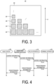
- FIG. 2 is a diagram for describing an example of the wireless communication system according to the first embodiment.
- the communication system 1 is configured to, for example, appropriately perform large-capacity communication in each room of a user in a collective housing or the like which is even a location where visibility of the base station 10 is poor.
- a communication system using millimeter waves for the 5G or the like is applied to the collective housing or the like, steel frames, columns, walls, floors, and the like may be obstacles.
- the millimeter waves are expected to be guided indoors from a large opening surface such as window glass.
- a direction in which the window glass is installed in the collective housing or the like may be limited to one direction, it may be difficult to perform millimeter wave communication in the room depending on a positional relationship with the base station 10.
- the refractive radio wave obtained by refracting the radio wave from the base station 10 by use of the radio wave refracting plate 12 is relayed by the relay apparatus 14 through the window glass to enable millimeter wave communication in the room.
- FIG. 2 includes a room R and a balcony V.
- the room R and the balcony V are examples of the room in the collective housing.
- the balcony V is in a service area of the base station 10
- the room R is in an out-of-coverage area of the base station 10.
- the radio wave refracting plate 12 is installed outdoors.
- the radio wave refracting plate 12 is, for example, installed in the balcony V.
- the radio wave refracting plate 12 may be fixed to a handrail H or the like so as not to be blown by, for example, wind.
- the radio wave refracting plate 12 may be installed at a position where the relay apparatus 14 can be seen from the window glass G, for example.
- the radio wave refracting plate 12 may be installed, for example, such that a surface direction thereof is at a right angle with respect to a surface direction of the window glass G.
- the radio wave refracting plate 12 may include a mechanism, for example, capable of rotating in a horizontal direction or changing an elevation/depression angle.
- the radio wave refracting plate 12 may be constructed to be, for example, installed inside a resin case and be able to rotate or incline inside the case. In this case, the direction of refraction of the radio waves can be adjusted while the radio wave refracting plate 12 is fixed so as not to be blown by wind or the like.
- the radio wave refracting plate 12 may include, for example, a film. In this case, the radio wave refracting plate 12 may be attached to the window glass G outdoors or indoors.
- the relay apparatus 14 is installed indoors.
- the relay apparatus 14 is installed in the room R.
- the relay apparatus 14 may be installed in various locations on a floor, wall, ceiling, furniture, or the like in the room R, for example.
- the relay apparatus 14 may be fixedly installed in the room R, for example.
- the relay apparatus 14 may be movably installed in the room R, for example.
- the radio wave refracting plate 12 is installed at a position capable of receiving a radio wave W1 transmitted from the base station 10, for example.
- the installation location of the radio wave refracting plate 12 may be set based on the position of the base station 10 and the installation location of the relay apparatus 14.
- the radio wave refracting plate 12 may be installed at a position where visibility when viewed from the base station 10 and the relay apparatus 14 is good, for example.
- the radio wave refracting plate 12 may be set at a position visible from the positions of the base station 10 and relay apparatus 14, for example.
- the radio wave refracting plate 12 may be installed such that the surface direction of the radio wave refracting plate 12 is orthogonal to an incident direction of the radio wave W1 from the base station 10.
- an angle of the radio wave refracting plate 12 with respect to the base station 10 may vary depending on the relationship between the position of the base station 10 and the position where the radio wave refracting plate 12 is installed. For example, when the radio wave refracting plate 12 is installed in each room of the collective housing, the angle of the radio wave refracting plate 12 with respect to the base station 10 may vary from room to room.
- the radio wave refracting plate 12 can refract the radio wave W1 from the base station 10 to emit as a refractive radio wave W2 through the window glass G toward the relay apparatus 14.
- the radio wave refracting plate 12 may be configured to, for example, amplify a signal level of the radio wave W1 from the base station 10 while refracting to emit the refractive radio wave W2.
- the radio wave refracting plate 12 may be configured, for example, such that the emitted refractive radio wave W2 obtained by refracting the radio wave W1 from the base station 10 converges at the position of the relay apparatus 14.
- the radio wave refracting plate 12 may be configured to amplify the signal level of the radio wave W1 while refracting with taking into consideration of an attenuation rate of the radio wave, when the window glass G is made of a glass having a relatively large attenuation rate of radio waves such as a heat absorbing glass or a heat reflecting glass, for example.
- an antireflection film to avoid reflection of the radio wave in the predetermined frequency band may be attached to the window glass G at least a portion between the radio wave refracting plate 12 and the relay apparatus 14.
- the radio wave refracting plate 12 may be configured to, for example, when the wall of the room R is made of wood, refract the radio wave W1 from the base station 10 to emit as the refractive radio wave W2 through the wood wall toward the relay apparatus 14.
- the radio wave refracting plate 12 may be installed outdoors in the vicinity of the wood wall, for example.
- the radio wave refracting plate 12 may be configured, for example, such that the emitted refractive radio wave W2 obtained by refracting the radio wave W1 from the base station 10 converges at the position of the relay apparatus 14 through the wood wall of the room R.
- the radio wave refracting plate 12 may be installed, for example, such that the surface direction thereof is in parallel with the surface direction of the window glass G.
- the radio wave refracting plate 12 can adjust the refractive angle of the refractive radio wave W2 with respect to the radio wave W1 from the base station 10 by, for example, rotating in a state of the surface of the radio wave refracting plate 12 facing the window glass G.
- the radio wave refracting plate 12 may be configured to have characteristics set depending on the nature of the window glass G when the radio wave refracting plate 12 includes a film attached to the window glass G.
- the radio wave refracting plate 12 may be configured, for example, depending on reflective characteristics of the window glass G with respect to the radio wave W1 from the base station 10.
- the radio wave refracting plate 12 may be configured, for example, to cancel out a reflection of the radio wave W1 on the window glass G.
- the radio wave refracting plate 12 may be configured such that, for example, a phase of a reflective wave from the window glass G with respect to the radio wave W1 and a phase of a reflective wave from the radio wave refracting plate 12 are opposite to each other.
- An area of the radio wave refracting plate 12 is preferably configured to be larger than an antenna effective area of the relay apparatus 14.
- the radio wave refracting plate 12 is preferably configured to have the area formed larger to converge the refractive radio wave W2 to the relay apparatus 14.
- the radio wave refracting plate 12 is preferably configured such that an electrical power density at the position of the relay apparatus 14 is greater than an electrical power density at the position of the radio wave refracting plate 12. This increases a radio wave intensity that can be received by the relay apparatus 14 to allow stable communication.
- a focal point at which the refractive radio wave W2 is converged is preferably on a straight line connecting the radio wave refracting plate 12 and the relay apparatus 14, and closer to the relay apparatus 14 than a midpoint between the radio wave refracting plate 12 and the relay apparatus 14.
- the focal point of the refractive radio wave W2 may be closer to an inner side of the room than the relay apparatus 14.
- a length of one side of the radio wave refracting plate 12 is preferably configured to be smaller than 2L ⁇ tan(w) where w (deg) represents a half width of an antenna (not illustrated) of the base station 10 and L (m) represents a distance between the base station 10 and the radio wave refracting plate 12.
- the radio wave refracting plate 12 may be configured to refract the radio wave W1 from the base station 10 to emit as the refractive radio wave W2 toward the relay apparatus 14, regardless of the frequency of the band of the radio wave W1 from the base station 10.
- a plurality of radio wave refracting plates 12 may be installed depending on the frequency of the band.
- the radio wave refracting plate 12 may include unit structures (elements) two-dimensionally arranged on a plane.
- the unit structures may be arranged such that the phase changes along a direction A when the radio wave W1 from the base station 10 passes through the radio wave refracting plate 12.
- the direction A may be a direction parallel to a plane including, as sides, a straight line connecting the base station 10 and the radio wave refracting plate 12, and a straight line connecting the radio wave refracting plate 12 and the relay apparatus 14.
- the radio wave refracting plate 12 may change the frequency band of the radio wave of which the phase is to be changed and an amount of change in the phase, depending on a shape, such as a size and shape of the unit structure, for example.
- the refractive angle can be adjusted by changing the size and shape of the unit structure.
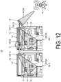
- FIG. 3 is a diagram schematically illustrating an example of the radio wave refracting plate 12.
- the radio wave refracting plate 12 may include a substrate 20, elements 22, elements 24, elements 26, and elements 28, for example.
- the elements 22, the elements 24, the elements 26, and the elements 28 may be formed on the substrate 20.
- the substrate 20 may have a rectangular shape of 30 cm x 30 cm, for example, but is not limited thereto.
- the elements 22, 24, 26, and 28 may be two-dimensionally arranged on the substrate 20. Specifically, in FIG. 3 , a plurality of elements 22 may be arranged in a line in the bottom row of the substrate 20. In the substrate 20, a plurality of elements 24 may be arranged in a line in a row above the row where the elements 22 are arranged. In the substrate 20, a plurality of elements 26 may be arranged in a line in a row above the row where the elements 24 are arranged.
- a plurality of elements 28 may be arranged in a line in a row above the row where the elements 26 are arranged.
- a plurality of elements 22 may be arranged in a line in a row above the row where the elements 28 are arranged.
- the radio wave refracting plate 12 may have a structure in which a plurality of elements having different sizes are periodically arranged.
- the elements 22 to 28 may be different in the frequency band of the radio wave to be changed and the amount of change in the phase.
- the elements 22 to 28 have the rectangular shapes, without limitation.
- the frequency band of the radio wave to be refracted and the amount of change in the phase can be adjusted by varying the sizes and shapes of the element 22, the element 24, and the element 26, and the element 28.
- the relay apparatus 14 is configured to perform wireless communication with a terminal apparatus 16 located in the room R, based on the refractive radio wave W2 received from the radio wave refracting plate 12, for example.
- the terminal apparatus 16 may be a communication apparatus including a smartphone.
- the relay apparatus 14 may be configured to emit radio waves toward a whole of the room R in performing millimeter wave communication for the 5G, the 6G, or the like with the terminal apparatus 16, for example.
- the relay apparatus 14 may be configured to emit a beam toward the terminal apparatus 16 in performing millimeter wave communication for the 5G, the 6G, or the like with the terminal apparatus 16, for example.
- the relay apparatus 14 may be configured to wirelessly communicate with the terminal apparatus 16 using Wi-Fi, for example.
- FIG. 4 is a sequence diagram illustrating an example of a flow of processing for the communication system according to the first embodiment.
- FIG. 4 For example, as illustrated in FIG. 2 . Processing of communication between the base station 10 and the terminal apparatus 16 incapable of directly receiving millimeter waves from base station 10, in millimeter wave communication using millimeter waves for the 5G, the 6G, or the like, is illustrated.
- the base station 10 transmits, to the radio wave refracting plate 12, a radio wave of millimeter waves including content information related to various contents such as video, music, and audio (step S10).
- the radio wave refracting plate 12 refracts the radio wave of millimeter waves including the content information received from the base station 10 to transmit as a refractive radio wave of millimeter waves including the content information to the relay apparatus 14 (step S12).
- the relay apparatus 14 when receiving the refractive radio wave of millimeter wave from the radio wave refracting plate 12, transmits the content information included in the refractive radio wave by using millimeter waves, Wi-Fi or the like to the terminal apparatus 16 (step S14). Accordingly, the communication system 1 can guide the content information transmitted from the base station 10 to the terminal apparatus 16.
- the communication system 1 can also transmit predetermined information from the terminal apparatus 16 to the base station 10.
- the terminal apparatus 16 transmits the predetermined information to be transmitted to the base station 10 to the relay apparatus 14 by using millimeter waves, Wi-Fi, or the like (step S16).
- the relay apparatus 14 outputs the radio wave of millimeter waves including the predetermined information received from the terminal apparatus 16 to the radio wave refracting plate 12 (step S18).
- the radio wave refracting plate 12 refracts the radio wave of millimeter waves including the predetermined information received from the relay apparatus 14 to transmit as a refractive radio wave of millimeter waves including the predetermined information to the base station 10 (step S20). Accordingly, the communication system 1 can guide the predetermined information transmitted from the terminal apparatus 16 to the base station 10.
- FIG. 5 is a block diagram illustrating a configuration example of the base station according to the first embodiment.
- the base station 10 includes a communicator 30, a storage 32, and a controller 34, for example.
- the communicator 30 is a wireless communication interface performing wireless communication with an external apparatus.
- the communicator 30 is configured to wirelessly communicate with the relay apparatus 14, the terminal apparatus 16, or the like.
- the communicator 30 corresponds to millimeter wave communication for the 5G, the 6G, or the like, for example.
- the storage 32 is a memory storing various types of information.
- the storage 32 is configured to store information such as arithmetic content and a program of the controller 34, for example.
- the storage 32 may include at least one selected from the group consisting of, for example, a RAM (random access memory), a primary storage device such a ROM (read only memory), and an external storage device such as an HDD (hard disk drive).
- the controller 34 is configured to control an operation of each unit in the base station 10.
- the controller 34 is implemented by, for example, a CPU (central processing unit), an MPU (micro processing unit), and the like executing the program stored in the storage 32 on the RAM (random access memory) or the like used as a work space.
- the controller 34 may be implemented by, for example, an integrated circuit such as an ASIC (application specific integrated circuit) or a FPGA (field programmable gate array).
- the controller 34 may be implemented in a combination of hardware and software.
- FIG. 6 is a block diagram illustrating a configuration example of the relay apparatus according to the first embodiment.
- the relay apparatus 14 As illustrated in FIG. 6 , the relay apparatus 14, a first communicator 40, a second communicator 42, a storage 44, and a controller 46 are included.
- the first communicator 40 is a wireless communication interface performing wireless communication with an external apparatus.
- the first communicator 40 is configured to wirelessly communicate with the base station 10, the terminal apparatus 16, or the like.
- the first communicator 40 corresponds to millimeter wave communication for the 5G, the 6G, or the like, for example.
- the second communicator 42 is a wireless communication interface performing wireless communication with an external apparatus.
- the second communicator 42 is configured to wirelessly communicate with the terminal apparatus 16.
- the second communicator 42 corresponds to short-range wireless communication such as Wi-Fi, for example. Note that when the relay apparatus 14 communicates with the terminal apparatus 16 using millimeter waves, the second communicator 42 may not be necessarily provided.
- the storage 44 is a memory storing various types of information.
- the storage 44 is configured to store information such as arithmetic content and a program of the controller 46, for example.
- the storage 44 includes at least one selected from the group consisting of, for example, a RAM, a primary storage device such a ROM, and an external storage device such as an HDD.
- the controller 46 is configured to control an operation of each unit in the base station 10.
- the controller 46 is implemented by, for example, a CPU, an MPU, and the like executing the program stored in the storage 44 on the RAM or the like used as a work space.
- the controller 46 may be implemented by an integrated circuit such as an ASIC or a FPGA, for example.
- the controller 46 may be implemented in a combination of hardware and software.
- the communication system 1 is configured to refract the radio wave of millimeter waves transmitted from the base station 10 by use of the radio wave refracting plate 12 to guide to the relay apparatus 14 installed in the room R in which it is difficult to perform communication using millimeter waves. Accordingly, in the first embodiment, communication using millimeter waves can be appropriately performed by using the radio wave refracting plate 12 and the relay apparatus 14 even in an out-of-coverage area. In the first embodiment, the radio wave refracting plate 12 only needs to be arranged between the base station 10 and the relay apparatus 14, so communication using millimeter waves can be easily performed even in an out-of-coverage area.
- the radio wave refracting plate 12 can refract and emit the radio wave of millimeter waves transmitted from the base station 10 to be converged to the relay apparatus 14. Accordingly, in the first embodiment, communication using millimeter waves can be more appropriately performed even in an out-of-coverage area.
- the access point does not need to be provided. Accordingly, in the first embodiment, a power supply for the access point is not required, which is advantageous in terms of cost.
- a work for making a hole in the house or the like is not required for drawing the optical communication line and the like to the room R for performing high-speed communication. Accordingly, in the first embodiment, an effort or the like of the work of construction is not taken, which is advantageous in terms of cost.
- FIG. 7 is a diagram for describing an example of a wireless communication system according to the variation of the first embodiment.
- a communication system 1A includes the base station 10 and the radio wave refracting plate 12.
- the communication system 1A differs from the communication system 1 illustrated in FIGs. 1 and 2 in that the communication system 1A does not include the relay apparatus 14.
- the radio wave refracting plate 12 may be installed at a position where visibility when viewing the base station 10 and the whole of the room R is good, for example.
- the radio wave refracting plate 12 may be configured to emit the radio wave received from the base station 10 as a refractive radio wave toward inside the room R.
- the radio wave refracting plate 12 may be configured, for example, to emit the radio wave received from the base station 10 as a refractive radio wave to be spread to the whole of the room R in a horizontal direction of the room R.
- the radio wave refracting plate 12 may be designed such that a beam width in a horizontal direction of the refractive radio wave W2 is wider than a beam width in a vertical direction. In this case, a large range area of the room R can be covered and the radio waves are not unnecessarily spread in the vertical direction, and thus, the terminal apparatus 16 can receive large electrical power to efficiently perform communication.
- the radio wave refracting plate 12 may be designed such that the refractive radio waves W2 converge, and have a focal point near a window frame of the window glass G or between the glass and the glass.
- the window frame is non-metal, even if the window glass is made of a material having a high attenuation such as heat reflecting glass or heat absorbing glass, the refractive radio wave W2 passes through the window frame portion through which the radio wave is likely to pass, and thus the radio waves efficiently penetrate indoors to allow stable communication.
- the radio wave refracting plate 12 may be designed to allow convergence to one point, or may be designed to allow convergence to a line segment along the window frame of the window glass G. A direction of the line segment is preferred in the vertical direction.
- a location where the refractive radio wave W2 converges is preferably an end of the window glass G on a side closer to the radio wave refracting plate 12. This makes it possible to efficiently implement a communication area in the whole of the room R.
- the terminal apparatus 16 is configured to receive the refractive radio wave from the radio wave refracting plate 12 to receive the radio wave transmitted from the base station 10.
- the communication system 1A is configured to guide the content information transmitted from the base station 10 directly to the terminal apparatus 16 via the radio wave refracting plate 12.
- the terminal apparatus 16 transmits the radio waves including the predetermined information to the radio wave refracting plates 12 to transmit the radio waves to the base station 10.
- the communication system 1A is configured to guide the predetermined information transmitted from the terminal apparatus 16 directly to the base station 10 via the radio wave refracting plate 12.
- the communication system 1A is configured to refract the radio wave of millimeter waves transmitted from the base station 10 by use of the radio wave refracting plate 12 to guide to the room R in which it is difficult to perform communication using millimeter waves. Accordingly, in the first embodiment, communication between the base station 10 and the terminal apparatus 16 using millimeter waves can be appropriately performed by using the radio wave refracting plate 12 even in an out-of-coverage area.
- FIG. 8 is a block diagram illustrating a configuration example of the wireless communication system according to the second embodiment.
- a communication system 1B includes the base station 10, the radio wave refracting plate 12, the relay apparatus 14 installed in each of a first house 50-1 to a n-th house 50-n (n is an integer of 2 or more), and a first polarization-supported refracting plate 18-1 to a n-th polarization-supported refracting plate 18-n.
- the first polarization-supported refracting plate 18-1 to the n-th polarization-supported refracting plate 18-n, if not necessarily distinguished, may be collectively referred to as the polarization-supported refracting plate 18.
- the first house 50-1 to the n-th house 50-n if not necessarily distinguished, may be collectively referred to as the house 50.
- FIG. 9 is a diagram for describing an example of the wireless communication system according to the second embodiment.
- FIG. 9 illustrates the first house 50-1 and the second house 50-2.
- the first house 50-1 and the second house 50-2 may be rooms next to each other in the collective housing.
- the first polarization-supported refracting plate 18-1 is installed in a balcony V1 in the first house 50-1.
- the second polarization-supported refracting plate 18-2 is installed in a balcony V2 in the second house 50-2.
- the first polarization-supported refracting plate 18-1 and the second polarization-supported refracting plate 18-2 may be fixed to a handrail H1 and a handrail H2, respectively, so as not to be blown by, for example, wind.
- a radio wave W10 from the base station 10 is refracted, by the radio wave refracting plate 12, as a refractive radio wave W11 in parallel to a surface of the window glass G on a side of the respective balconies V.
- the radio wave W10 from the base station 10 contains a vertical polarization and a horizontal polarization.
- the radio wave refracting plate 12 may be configured to also refract a radio wave of an inclined polarization.
- the radio wave refracting plate 12 is configured to refract the radio wave W10 from the base station 10 in a direction of the first polarization-supported refracting plate 18-1.
- the radio wave refracting plate 12 includes a plurality of structures designed to have a refractive angle for each different frequency band at which refractive angle a radio wave incident in a direction of a line connecting the base station 10 with the radio wave refracting plate 12 is refracted to a direction of a line connecting the radio wave refracting plate 12 with the first polarization-supported refracting plate 18-1. Note that a plurality of radio wave refracting plates 12 may be disposed for different frequency bands.
- the first polarization-supported refracting plate 18-1 includes a plurality of structures designed to have a refractive angle for each different frequency band at which refractive angle a radio wave incident in a direction of a line connecting the radio wave refracting plate 12 with the first polarization-supported refracting plate 18-1 is refracted to a direction of a line connecting the first polarization-supported refracting plate 18-1 with the room of the first house 50-1.
- a plurality of first polarization-supported refracting plates 18-1 may be disposed for different frequency bands.
- the second polarization-supported refracting plate 18-2 includes a plurality of structures designed to have a refractive angle for each different frequency band at which refractive angle a radio wave incident in a direction of a line connecting the first polarization-supported refracting plate 18-1 with the second polarization-supported refracting plate 18-2 is refracted to a direction of a line connecting the second polarization-supported refracting plate 18-2 with the room of the first house 50-1.
- a plurality of second polarization-supported refracting plates 18-2 may be disposed for different frequency bands.
- the first polarization-supported refracting plate 18-1 receives the refractive radio wave W11 from the radio wave refracting plate 12.
- the first polarization-supported refracting plate 18-1 passes therethrough at least a part of the vertical polarization and the horizontal polarization contained in the refractive radio wave W11, as a passed-through radio wave W12.
- the first polarization-supported refracting plate 18-1 passes therethrough at least a part of the vertical polarization and the horizontal polarization contained in the refractive radio wave W 11, as a refractive radio wave W13 in a direction inside the room of the first house 50-1.
- the refractive radio wave W13 is relayed to the relay apparatus 14 via the window glass G to enable millimeter wave communication, for example.
- the second polarization-supported refracting plate 18-2 receives the passed-through radio wave W12 from first polarization-supported refracting plate 18-1.
- the second polarization-supported refracting plate 18-2 passes therethrough at least a part of the vertical polarization and the horizontal polarization contained in the passed-through radio wave W12, as a passed-through radio wave W14.
- the second polarization-supported refracting plate 18-2 passes therethrough at least a part of the vertical polarization and the horizontal polarization contained in the passed-through radio wave W12, as a passed-through radio wave W15 in a direction toward the inside of the room of the second house 50-2.
- the refractive radio wave W15 is relayed to the relay apparatus 14 via the window glass G to enable millimeter wave communication, for example.
- the polarization-supported refracting plate 18 is installed so that a radio wave area can be created even in a room where visibility of the base station 10 from the window glass G of the room is poor so long as the rooms are at the same floor in the collective housing.
- the radio wave refracting plate 12 has a configuration same as, and/or similar to, the radio wave refracting plate 12 illustrated in FIG. 3 .
- the direction A may be a direction parallel to a plane defined by a line connecting the base station 10 with the radio wave refracting plate 12 and a line connecting the radio wave refracting plate 12 with the first polarization-supported refracting plate 18-1.
- FIG. 10 is a diagram schematically illustrating an example of the polarization-supported refracting plate 18 according to the second embodiment.
- the polarization-supported refracting plate 18 may include a substrate 60, elements 62, elements 64, elements 66, and elements 68, for example.
- the elements 62, the elements 64, the element 66s, and the elements 68 are formed in a rectangular shape.
- the polarization-supported refracting plate 18 may be configured such that the phase changes only with respect to a polarization in the direction A, and the phase does not change with respect to a polarization orthogonal to the direction A.
- the polarization-supported refracting plate 18 may include unit structures (elements) two-dimensionally arranged on a plane.
- the unit structures may be arranged such that the phase changes along the direction A when a carrier passes through the polarization-supported refracting plate 18.
- the direction A may be a direction parallel to a plane defined by a line connecting the radio wave refracting plate 12 with the first polarization-supported refracting plate 18-1 and a line connecting the first polarization-supported refracting plate 18-1 with the first house 50-1.
- the direction A may be a direction parallel to a plane defined by a line connecting the first polarization-supported refracting plate 18-1 with the second polarization-supported refracting plate 18-2 and a line connecting the second polarization-supported refracting plate 18-2 with the second house 50-2.
- the polarization-supported refracting plate 18 is designed to not only refract but also diffuse the radio wave of a polarization incident from the base station 10.
- a length of one side of the polarization-supported refracting plate 18 is preferably configured to be smaller than 2L ⁇ tan(w) where w (deg) represents a half width of an antenna (not illustrated) of the base station 10 and L (m) represents a distance between the base station 10 and the radio wave refracting plate 12.
- the polarization-supported refracting plate 18 is designed to have an operational polarization angle ⁇ in a range from 0° to 90°.
- the operating polarization angle ⁇ can be designed to have any value to change a ratio of electrical powers of the radio waves propagating in a refractive direction and a direct traveling direction. Note that, as described above, the radio waves radiated by the base station 10 contain the polarizations of both the vertical polarization and the horizontal polarization.
- FIG. 12 is a diagram for describing an example of a communication system according to a first variation of the second embodiment.
- FIG. 12 illustrates an example of propagating radio waves from the base station to two houses of the first house 50-1 and the second house 50-2.
- a first polarization-supported refracting plate 18A-1 is installed in the balcony V1 in the first house 50-1.
- a second polarization-supported refracting plate 18A-2 is installed in the balcony V2 in the second house 50-2.
- the radio wave refracting plate 12 refracts a radio wave W10A from the base station 10 to emit as a refractive radio wave W 11A to the first polarization-supported refracting plate 18A-1. Assume that the refractive radio wave W11A has 50% of the vertical polarization components and 50% of the horizontal polarization components of the total.
- the first polarization-supported refracting plate 18A-1 is designed to have the operational polarization angle ⁇ of 0°, for example. In other words, the first polarization-supported refracting plate 18A-1 is designed to refract the horizontal polarization only.
- the first polarization-supported refracting plate 18A-1 makes all components of the vertical polarization of the refractive radio wave W11, as a passed-through radio wave W12A, go straight in the direction of the second polarization-supported refracting plate 18A-2.
- the passed-through radio wave W12A contains only the vertical polarization.
- An electrical power of the passed-through radio wave W12A is 50% of the electrical power of the refractive radio wave W11A.
- the first polarization-supported refracting plate 18A-1 refracts all components of the horizontal polarization of the refractive radio wave W11, as a refractive radio wave W13A, in the direction of the room of the first house 50-1.
- the refractive radio wave W13A contains only the horizontal polarization.
- An electrical power of the refractive radio wave W13A is 50% of the electrical power of the refractive radio wave W11 A.
- the second polarization-supported refracting plate 18A-2 is designed to have the operational polarization angle ⁇ of 90°, for example.
- the second polarization-supported refracting plate 18A-2 is designed to refract the vertical polarization only.
- the second polarization-supported refracting plate 18A-2 refracts the entire passed-through radio wave W12A, as a refractive radio wave W15A, in the direction of the room of the second house 50-2.
- An electrical power of the refractive radio wave W15A is 50% of the electrical power of the refractive radio wave W11A.
- the operating polarization angles ⁇ of the first polarization-supported refracting plate 18A-1 and the second polarization-supported refracting plate 18A-2 are designed as illustrated in FIG. 12 , so that the electrical power of the refractive radio wave W11A can be efficiently propagated evenly to the first house 50-1 and the second house 50-2.
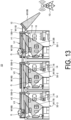
- FIG. 13 is a diagram for describing an example of the communication system according to the second variation of the second embodiment.
- FIG. 13 illustrates an example of propagating radio waves from the base station to three houses of the first house 50-1, the second house 50-2, and the third house 50-3.
- a first polarization-supported refracting plate 18B-1 is installed in the balcony V1 in the first house 50-1.
- a second polarization-supported refracting plate 18B-2 is installed in the balcony V2 in the second house 50-2.
- a third polarization-supported refracting plate 18B-3 is installed in a balcony V3 in the third house 50-3.
- the radio wave refracting plate 12 refracts a radio wave W10B from the base station 10 to emit as a refractive radio wave W11B to the first polarization-supported refracting plate 18B-1. Assume that the refractive radio wave W11B has 50% of the vertical polarization components and 50% of the horizontal polarization components of the total.
- the first polarization-supported refracting plate 18B-1 is designed to have the operational polarization angle ⁇ of 45°, for example.
- the first polarization-supported refracting plate 18B-1 is designed to refract halves of both the vertical polarization and the horizontal polarization of the received radio wave.
- the first polarization-supported refracting plate 18B-1 makes the halves of both the vertical polarization and the horizontal polarization of the refractive radio wave W11B, as a passed-through radio wave W12B, go straight in a direction of the second polarization-supported refracting plate 18B-2.
- the passed-through radio wave W12B has 25% of the vertical polarization components and 25% of the horizontal polarization components of the total.
- An electrical power of the passed-through radio wave W12B is 50% of the electrical power of the refractive radio wave W11B.
- the first polarization-supported refracting plate 18B-1 refracts halves of both the vertical polarization and the horizontal polarization of the refractive radio wave W11B, as a refractive radio wave W13B, in the direction of the room of the first house 50-1.
- the refractive radio wave W13B has 25% of the vertical polarization components and 25% of the horizontal polarization components of the total.
- An electrical power of the refractive radio wave W13B is 50% of the electrical power of the refractive radio wave W11B.
- the second polarization-supported refracting plate 18B-2 is designed to have the operational polarization angle ⁇ of 45°, for example.
- the second polarization-supported refracting plate 18B-2 makes halves of both the vertical polarization and the horizontal polarization of the passed-through radio wave W12B, as a passed-through radio wave W14B, go straight in a direction of the third polarization-supported refracting plate 18B-3.
- the passed-through radio wave W14B has 13% of the vertical polarization components and 13% of the horizontal polarization components of the total.
- An electrical power of the passed-through radio wave W14B is 25% of the electrical power of the refractive radio wave W11B.
- the second polarization-supported refracting plate 18B-2 refracts halves of both the vertical polarization and the horizontal polarization of the passed-through radio wave W12B, as a refractive radio wave W15B, in the direction of the room of the second house 50-2. Assume that the refractive radio wave W15B has 13% of the vertical polarization components and 13% of the horizontal polarization components of the total. An electrical power of the refractive radio wave W15B is 25% of the electrical power of the refractive radio wave W11B.
- the third polarization-supported refracting plate 18B-3 is designed to have the operational polarization angle ⁇ of 45°, for example.
- the third polarization-supported refracting plate 18B-3 makes halves of both the vertical polarization and the horizontal polarization of the passed-through radio wave W14B, as a passed-through radio wave W16B go straight.
- the passed-through radio wave W16B has 6% of the vertical polarization components and 6% of the horizontal polarization components of the total.
- An electrical power of the passed-through radio wave W14B is 13% of the electrical power of the refractive radio wave W11B.
- the third polarization-supported refracting plate 18B-3 refracts halves of both the vertical polarization and the horizontal polarization of the passed-through radio wave W14B, as a refractive radio wave W17B, in the direction of the room of the third house 50-3.
- the refractive radio wave W17B has 6% of the vertical polarization components and 6% of the horizontal polarization components of the total.
- An electrical power of the refractive radio wave W17B is 13% of the electrical power of the refractive radio wave W11B.
- the operating polarization angles ⁇ of the first polarization-supported refracting plate 18B-1 to the third polarization-supported refracting plate 18B-3 are designed as illustrated in FIG. 13 , so that the electrical power of the refractive radio wave W11B can be propagated to the first house 50-1 to the third house 50-3.
- the electrical power intensity is made to be half each time propagating to the next house.
- the first polarization-supported refracting plate 18B-1 to the third polarization-supported refracting plate 18B-3 illustrated in FIG. 13 are described as having the same operating polarization angle ⁇ , but the present disclosure is not limited thereto.
- the operational polarization angles ⁇ of the first polarization-supported refracting plate 18B-1 to the third polarization-supported refracting plate 18B-3 may be different from each other.
- the first polarization-supported refracting plate 18B-1 may be designed to have the operational polarization angle ⁇ of 30°, for example.
- the passed-through radio wave W12B may have 38% of the vertical polarization components and 13% of the horizontal polarization components of the total.
- the electrical power of the passed-through radio wave W12B is 50% of the electrical power of the refractive radio wave W11B.
- the refractive radio wave W13B may have 13% of the vertical polarization components and 38% of the horizontal polarization components of the total.
- the electrical power of the refractive radio wave W13B is 50% of the electrical power of the refractive radio wave W11B.
- the second polarization-supported refracting plate 18B-2 may be designed to have the operational polarization angle ⁇ of 60°, for example.
- the passed-through radio wave W14B may have 14% of the vertical polarization components and 5% of the horizontal polarization components of the total.
- the electrical power of the passed-through radio wave W14B is 19% of the electrical power of the refractive radio wave W11B.
- the refractive radio wave W15B may have 23% of the vertical polarization components and 8% of the horizontal polarization components of the total.
- the electrical power of the refractive radio wave W15B is 31% of the electrical power of the refractive radio wave W11B.
- the third polarization-supported refracting plate 18B-3 may be designed to have the operational polarization angle ⁇ of 45°, for example.
- the passed-through radio wave W16B may have 9% of the vertical polarization components and 0% of the horizontal polarization components of the total.
- the electrical power of the passed-through radio wave W16B is 9% of the electrical power of the refractive radio wave W11B.
- the refractive radio wave W17B may have 5% of the vertical polarization components and 5% of the horizontal polarization components of the total.
- the electrical power of the refractive radio wave W17B is 9% of the electrical power of the refractive radio wave W11B.
- each ratio of the electrical powers can be roughly estimated by decomposing the polarization contained in the radio wave from the base station 10 into the vertical components and the horizontal components in accordance with the operating polarization angle ⁇ .
- the design can be made to effectively distribute the electrical power in accordance with the magnitude of the electrical power received from the base station 10, the number of households drawing the radio waves, the use case, or the like.
- the second embodiment can freely build the system.
- a reflector has been known that is formed of a metal plate or the like in order to bend the radio waves from the base station 10 in a desired direction such as that of a terminal apparatus or the like.
- the reflector has a problem that the travel direction of the radio wave after reflection is sensitive to an installation angle, so it is difficult to adjust the angle during the installation. Therefore, the reflector installed outdoors is rocked by wind to cause a problem that the communication state becomes unstable.
- FIG. 14 is a graph illustrating a relationship between a rotational angle of a radio wave refracting plate and a traveling direction of a radio wave.
- a graph G1 shows characteristics when a radio wave is vertically incident on the radio wave refracting plate 12 designed to have a refractive angle of 30°.
- a graph G2 shows characteristics when the vertically incident radio wave is vertically incident on a reflector reflecting a radio wave in a direction of a reflection angle of 30°.
- FIG. 14 illustrates a horizontal axis indicates the rotational angle of the radio wave refracting plate 12 or the reflector, and a vertical axis indicates a deviation of the radio wave in the refractive direction or the reflection direction.
- FIG. 14 illustrates the deviations in the refractive direction or the reflection direction with the rotational angle in a range of -10° to 10° with respect to the incident radio wave.
- the deviation in the refractive direction or in the reflection direction of 30° is 0° when the rotational angle is 0°.
- the radio wave refracting plate 12 has little change in the refractive angle, for example, even when the radio wave refracting plate 12 rotates in the range of -10° to 10° with reference to 0° with respect to the radio wave received, for example.
- the reflection angle changes greatly. For example, when the reflector is rotated 5°, the reflection angle changes by 10°. Specifically, when the reflector rotated ⁇ ° after the installation, the reflection direction of the radio wave deviates by 2 ⁇ °. In this case, the radio wave incident on the metal reflector at an incident angle of ⁇ ° is reflected at the reflection angle of ⁇ °, and thus the angle formed by the incident wave and the reflective wave is 2 ⁇ °.
- the ⁇ ° inclination with respect to the incident wave causes the incidence angle of ⁇ ° + ⁇ ° and the reflective wave of ⁇ ° + ⁇ °, and the angle formed by the incident wave and the reflective wave is 2 ⁇ ° + 2 ⁇ °.
- the relay antenna when the relay antenna is installed instead of the reflector, the relay antenna rotates ⁇ ° after the installation, the traveling direction of the radio wave deviates by ⁇ °. Furthermore, since the incident direction deviates by ⁇ °, the gain is significantly reduced when the installation is made with the maximum gain for the base station direction.
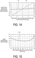
- FIG. 15 is a graph for describing changes in the refractive angle with respect to the rotational angle of the radio wave refracting plate.
- a graph G10 shows characteristics of the radio wave refracting plate 12.
- FIG. 15 illustrates the change in the refractive angle with the rotational angle in a range of -70° to 30° with respect to the incident radio wave. Note that in the example illustrated in FIG. 15 , the radio wave refracting plate 12 is designed to have a refractive angle of 30°.
- FIG. 15 is a graph for describing changes in the refractive angle with respect to the rotational angle of the radio wave refracting plate.
- a graph G10 shows characteristics of the radio wave refracting plate 12.
- FIG. 15 illustrates the change in the refractive angle with the rotational angle in a range of -70° to 30° with respect to the incident radio wave. Note that in the example illustrated in FIG. 15 , the radio wave refracting plate 12 is designed to have a refractive angle of 30
- the radio wave refracting plate 12 is in a direction perpendicular to the incident direction of the radio wave when the rotational angle is 0°, and is in a direction perpendicular to the refractive direction of the radio wave when the rotational angle is -30°.
- the radio wave refracting plate 12 indicates a good characteristic with the rotational angle in a range of approximately -40° to 10° with respect to the incident direction of the radio wave.
- a perpendicular direction of the radio wave refracting plate 12 preferably is positioned between the incident direction of the radio wave and the refractive direction.
- the perpendicular direction of the radio wave refracting plate 12 is preferably positioned from -30° to 0°.
Landscapes
- Engineering & Computer Science (AREA)
- Computer Networks & Wireless Communication (AREA)
- Signal Processing (AREA)
- Physics & Mathematics (AREA)
- Electromagnetism (AREA)
- Mobile Radio Communication Systems (AREA)
- Radio Relay Systems (AREA)
- Aerials With Secondary Devices (AREA)
Applications Claiming Priority (2)
| Application Number | Priority Date | Filing Date | Title |
|---|---|---|---|
| JP2020183310 | 2020-10-30 | ||
| PCT/JP2021/039176 WO2022091986A1 (ja) | 2020-10-30 | 2021-10-22 | 通信システム、通信方法、および電波屈折板の設置方法 |
Publications (2)
| Publication Number | Publication Date |
|---|---|
| EP4240044A1 true EP4240044A1 (de) | 2023-09-06 |
| EP4240044A4 EP4240044A4 (de) | 2024-10-02 |
Family
ID=81383926
Family Applications (1)
| Application Number | Title | Priority Date | Filing Date |
|---|---|---|---|
| EP21886104.5A Pending EP4240044A4 (de) | 2020-10-30 | 2021-10-22 | Kommunikationssystem, kommunikationsverfahren und verfahren zur installation einer funkwellenbrechungsplatte |
Country Status (4)
| Country | Link |
|---|---|
| EP (1) | EP4240044A4 (de) |
| JP (1) | JP7504217B2 (de) |
| CN (1) | CN116325362A (de) |
| WO (1) | WO2022091986A1 (de) |
Families Citing this family (9)
| Publication number | Priority date | Publication date | Assignee | Title |
|---|---|---|---|---|
| WO2024014411A1 (ja) * | 2022-07-14 | 2024-01-18 | 京セラ株式会社 | 無線通信システムおよび無線通信方法 |
| WO2024024426A1 (ja) * | 2022-07-28 | 2024-02-01 | 京セラ株式会社 | 電波制御装置および電波制御方法 |
| US20260051663A1 (en) * | 2022-08-25 | 2026-02-19 | Kyocera Corporation | Communication system and communication method |
| JPWO2024142824A1 (de) * | 2022-12-27 | 2024-07-04 | ||
| WO2024157897A1 (ja) * | 2023-01-26 | 2024-08-02 | Agc株式会社 | 電波伝搬制御部材、及び、アンテナシステム |
| JPWO2024161966A1 (de) * | 2023-01-31 | 2024-08-08 | ||
| WO2024257674A1 (ja) * | 2023-06-12 | 2024-12-19 | 京セラ株式会社 | 電波制御装置、及び電波制御板用の筐体 |
| WO2025004939A1 (ja) * | 2023-06-28 | 2025-01-02 | 京セラ株式会社 | 通信システム、および電波制御板の設置方法 |
| WO2025143109A1 (ja) * | 2023-12-28 | 2025-07-03 | 株式会社ジャパンディスプレイ | 電波反射装置 |
Family Cites Families (10)
| Publication number | Priority date | Publication date | Assignee | Title |
|---|---|---|---|---|
| JP2558554B2 (ja) * | 1990-11-30 | 1996-11-27 | デイエツクスアンテナ株式会社 | 電波の誘電体透過損失防止具 |
| JP2002164735A (ja) * | 2000-11-28 | 2002-06-07 | Kobe Steel Ltd | マイクロ波無線通信システムにおける無給電中継装置 |
| US6864857B2 (en) * | 2002-01-10 | 2005-03-08 | Raytheon Company | Optically transparent millimeter wave reflector |
| US7697929B2 (en) * | 2004-05-20 | 2010-04-13 | Pine Valley Investments, Inc. | Millimeter wave communication system |
| US8149178B2 (en) * | 2006-05-23 | 2012-04-03 | Intel Corporation | Millimeter-wave communication system with directional antenna and one or more millimeter-wave reflectors |
| JP5337432B2 (ja) * | 2007-11-30 | 2013-11-06 | 株式会社エヌ・ティ・ティ・ドコモ | 無線通信システム |
| JP6174086B2 (ja) | 2015-07-06 | 2017-08-02 | ソフトバンク株式会社 | 無線通信システム、無線通信制御装置及びプログラム |
| JP6965989B2 (ja) * | 2018-04-09 | 2021-11-10 | 株式会社村田製作所 | 電磁波伝搬制御部材、電磁波伝搬制御構造体、電磁波伝搬制御部材付きサッシ及び窓構造体 |
| US11342682B2 (en) * | 2018-05-24 | 2022-05-24 | Metawave Corporation | Frequency-selective reflector module and system |
| CN109149121B (zh) * | 2018-08-29 | 2021-01-12 | 北京交通大学 | 电磁介质直接覆盖漏波系统的真空管飞行列车通信系统 |
-
2021
- 2021-10-22 EP EP21886104.5A patent/EP4240044A4/de active Pending
- 2021-10-22 WO PCT/JP2021/039176 patent/WO2022091986A1/ja not_active Ceased
- 2021-10-22 CN CN202180069640.6A patent/CN116325362A/zh active Pending
- 2021-10-22 JP JP2022559098A patent/JP7504217B2/ja active Active
Also Published As
| Publication number | Publication date |
|---|---|
| JPWO2022091986A1 (de) | 2022-05-05 |
| JP7504217B2 (ja) | 2024-06-21 |
| US20230379010A1 (en) | 2023-11-23 |
| CN116325362A (zh) | 2023-06-23 |
| EP4240044A4 (de) | 2024-10-02 |
| WO2022091986A1 (ja) | 2022-05-05 |
Similar Documents
| Publication | Publication Date | Title |
|---|---|---|
| EP4240044A1 (de) | Kommunikationssystem, kommunikationsverfahren und verfahren zur installation einer funkwellenbrechungsplatte | |
| US10276921B2 (en) | Radiating closures | |
| US11664881B2 (en) | Method and apparatus for wireless infrastructure | |
| US12562496B2 (en) | Meta-structure based reflectarrays for enhanced wireless applications | |
| US20220278740A1 (en) | Meta-structure wireless infrastructure for beamforming systems | |
| US9728861B2 (en) | Reflector device, communication system using the same and communication method using the same | |
| JP5877894B2 (ja) | アンテナ | |
| Kalimulin et al. | Impact of mounting structures twists and sways on point-to-point millimeter-wave backhaul links | |
| US12597963B2 (en) | Communication system, communication method, and radio wave refracting plate installation method | |
| JP2003332836A (ja) | アンテナ | |
| WO2024127942A1 (ja) | 無線伝達システム | |
| CN205004427U (zh) | 一种天线 | |
| JP2001308797A (ja) | 無線伝送方法および装置 | |
| CN106357286B (zh) | 一种无线信号收发终端 | |
| US20260051663A1 (en) | Communication system and communication method | |
| CN204205068U (zh) | 一种天线 | |
| KR102347833B1 (ko) | 무선 통신 빔(beam)의 방향성을 변경하는 반사체 및 이를 포함하는 장치 | |
| WO2025105137A1 (ja) | 無線伝達システム | |
| CN118828544B (zh) | 一种应用于楼宇的天线布设方法和装置 | |
| US20250062786A1 (en) | Transmitter/receiver, transmission/reception device, and transmission/reception method | |
| JP2007060308A (ja) | 光空間伝送システム | |
| JP6836475B2 (ja) | 無線通信システム、無線通信方法及び無線通信装置 | |
| JP4410695B2 (ja) | 無線lanシステムおよびそのアンテナモジュール | |
| TW202410553A (zh) | 反射板、電磁波反射裝置及電磁波反射柵 | |
| WO2025115482A1 (ja) | 受信電力の測定方法、電力反射効率の計算方法、受信電力の測定プログラム、及び、電力反射効率の計算プログラム |
Legal Events
| Date | Code | Title | Description |
|---|---|---|---|
| STAA | Information on the status of an ep patent application or granted ep patent |
Free format text: STATUS: THE INTERNATIONAL PUBLICATION HAS BEEN MADE |
|
| PUAI | Public reference made under article 153(3) epc to a published international application that has entered the european phase |
Free format text: ORIGINAL CODE: 0009012 |
|
| STAA | Information on the status of an ep patent application or granted ep patent |
Free format text: STATUS: REQUEST FOR EXAMINATION WAS MADE |
|
| 17P | Request for examination filed |
Effective date: 20230419 |
|
| AK | Designated contracting states |
Kind code of ref document: A1 Designated state(s): AL AT BE BG CH CY CZ DE DK EE ES FI FR GB GR HR HU IE IS IT LI LT LU LV MC MK MT NL NO PL PT RO RS SE SI SK SM TR |
|
| DAV | Request for validation of the european patent (deleted) | ||
| DAX | Request for extension of the european patent (deleted) | ||
| A4 | Supplementary search report drawn up and despatched |
Effective date: 20240903 |
|
| RIC1 | Information provided on ipc code assigned before grant |
Ipc: H04W 84/04 20090101ALI20240828BHEP Ipc: H01Q 15/12 20060101ALI20240828BHEP Ipc: H01Q 15/02 20060101ALI20240828BHEP Ipc: H01Q 15/00 20060101ALI20240828BHEP Ipc: H01Q 15/14 20060101ALI20240828BHEP Ipc: H01Q 15/10 20060101ALI20240828BHEP Ipc: H04W 16/26 20090101AFI20240828BHEP |
|
| STAA | Information on the status of an ep patent application or granted ep patent |
Free format text: STATUS: EXAMINATION IS IN PROGRESS |
|
| 17Q | First examination report despatched |
Effective date: 20260217 |