EP4239807A2 - Mit markierungen konfigurierbarer datenkommunikationsporteinsatz zur anpassung der etikettierung und identifizierung von datenkommunikationsstationen - Google Patents
Mit markierungen konfigurierbarer datenkommunikationsporteinsatz zur anpassung der etikettierung und identifizierung von datenkommunikationsstationen Download PDFInfo
- Publication number
- EP4239807A2 EP4239807A2 EP23182685.0A EP23182685A EP4239807A2 EP 4239807 A2 EP4239807 A2 EP 4239807A2 EP 23182685 A EP23182685 A EP 23182685A EP 4239807 A2 EP4239807 A2 EP 4239807A2
- Authority
- EP
- European Patent Office
- Prior art keywords
- identification
- identification icon
- insert
- blank insert
- connector
- Prior art date
- Legal status (The legal status is an assumption and is not a legal conclusion. Google has not performed a legal analysis and makes no representation as to the accuracy of the status listed.)
- Granted
Links
Images




Classifications
-
- G—PHYSICS
- G02—OPTICS
- G02B—OPTICAL ELEMENTS, SYSTEMS OR APPARATUS
- G02B6/00—Light guides; Structural details of arrangements comprising light guides and other optical elements, e.g. couplings
- G02B6/24—Coupling light guides
- G02B6/36—Mechanical coupling means
- G02B6/38—Mechanical coupling means having fibre to fibre mating means
- G02B6/3807—Dismountable connectors, i.e. comprising plugs
- G02B6/3895—Dismountable connectors, i.e. comprising plugs identification of connection, e.g. right plug to the right socket or full engagement of the mating parts
-
- H—ELECTRICITY
- H01—ELECTRIC ELEMENTS
- H01R—ELECTRICALLY-CONDUCTIVE CONNECTIONS; STRUCTURAL ASSOCIATIONS OF A PLURALITY OF MUTUALLY-INSULATED ELECTRICAL CONNECTING ELEMENTS; COUPLING DEVICES; CURRENT COLLECTORS
- H01R13/00—Details of coupling devices of the kinds covered by groups H01R12/70 or H01R24/00 - H01R33/00
- H01R13/46—Bases; Cases
- H01R13/465—Identification means, e.g. labels, tags, markings
-
- G—PHYSICS
- G09—EDUCATION; CRYPTOGRAPHY; DISPLAY; ADVERTISING; SEALS
- G09F—DISPLAYING; ADVERTISING; SIGNS; LABELS OR NAME-PLATES; SEALS
- G09F23/00—Advertising on or in specific articles, e.g. ashtrays, letter-boxes
-
- G—PHYSICS
- G09—EDUCATION; CRYPTOGRAPHY; DISPLAY; ADVERTISING; SEALS
- G09F—DISPLAYING; ADVERTISING; SIGNS; LABELS OR NAME-PLATES; SEALS
- G09F3/00—Labels, tag tickets, or similar identification or indication means; Seals; Postage or like stamps
- G09F3/08—Fastening or securing by means not forming part of the material of the label itself
- G09F3/16—Fastening or securing by means not forming part of the material of the label itself by clamps
-
- G—PHYSICS
- G09—EDUCATION; CRYPTOGRAPHY; DISPLAY; ADVERTISING; SEALS
- G09F—DISPLAYING; ADVERTISING; SIGNS; LABELS OR NAME-PLATES; SEALS
- G09F7/00—Signs, name or number plates, letters, numerals, or symbols; Panels or boards
- G09F7/18—Means for attaching signs, plates, panels, or boards to a supporting structure
- G09F2007/1856—Means for attaching signs, plates, panels, or boards to a supporting structure characterised by the supporting structure
- G09F2007/1869—Means for attaching signs, plates, panels, or boards to a supporting structure characterised by the supporting structure plates fixed to instruments
-
- H—ELECTRICITY
- H01—ELECTRIC ELEMENTS
- H01R—ELECTRICALLY-CONDUCTIVE CONNECTIONS; STRUCTURAL ASSOCIATIONS OF A PLURALITY OF MUTUALLY-INSULATED ELECTRICAL CONNECTING ELEMENTS; COUPLING DEVICES; CURRENT COLLECTORS
- H01R13/00—Details of coupling devices of the kinds covered by groups H01R12/70 or H01R24/00 - H01R33/00
- H01R13/44—Means for preventing access to live contacts
- H01R13/443—Dummy plugs
-
- H—ELECTRICITY
- H01—ELECTRIC ELEMENTS
- H01R—ELECTRICALLY-CONDUCTIVE CONNECTIONS; STRUCTURAL ASSOCIATIONS OF A PLURALITY OF MUTUALLY-INSULATED ELECTRICAL CONNECTING ELEMENTS; COUPLING DEVICES; CURRENT COLLECTORS
- H01R24/00—Two-part coupling devices, or either of their cooperating parts, characterised by their overall structure
- H01R24/60—Contacts spaced along planar side wall transverse to longitudinal axis of engagement
- H01R24/62—Sliding engagements with one side only, e.g. modular jack coupling devices
- H01R24/64—Sliding engagements with one side only, e.g. modular jack coupling devices for high frequency, e.g. RJ 45
Definitions
- the present disclosure relates generally to a device and method of use thereof to label and customize data communication stations, outlets and connectors, and more particularly, to a device, a blank insert or a connector housing insert, configured to receive customizable indicia, and to be inserted into a conventional outlet in a data communications station to thereby identify and specify connectors and outlets and to enhance the labeling and identification of connectivity for the data communication station.
- Connectivity interfaces commonly known as, e.g., ports, connectors, sockets, outlets, jacks, adapters, plugs and the like, may be configured to receive a variety of connectors including, but not limited to, Registered Jacks (e.g. RJ-11, RJ-45 etc.), various category connectors (e.g.
- Connectors for the transmission of digital and analog voice, audio, video and data signals (collectively referred to herein generally as "connectors"), along various conductive media (e.g. copper wire, optical fiber) disposed within cabling.
- Connectors including, but not limited to, wall plates, patch panels, patch blocks, termination blocks, housings, etc., may include such connectivity interfaces configured to receive one or more of such connectors.
- data communication stations which can make it hard to keep track of the type of connectivity interface(s) configured to receive specific connector(s) within a particular data communication station as well as identification of the equipment or circuits to which specific cables are connected.
- Some existing data communication stations such as wall plates, may have identification icons at the top or bottom front facing surfaces of the wall plate for general identification purposes, but the identification icons are not typically specific to individual connectors or connectivity interfaces.
- a device referred to herein as a blank insert or a connector housing insert, configurable to receive customizable indicia, may be inserted into a connectivity interface in a data communications station in lieu of a standard connector, e.g. a RJ-45 jack or a fiber optic adapter into which fiber optic connector are disposed, to thereby identify, label and specify, the respective connector, the respective connectivity interface and/or other connectors and connectivity interfaces in the data communication station to enhance the labeling and identification of connectivity for the data communication station.
- a blank insert or connector housing insert may be useful not only to identify connectivity parameters of connectors and connectivity interfaces in the data communication station, but may also be used as place holders to reserve space for future expansion of connectivity interfaces in the data communication station.
- a method of assembling a data communication station includes providing a blank insert or connector housing insert, inserting the blank insert or connector housing insert into a connectivity interface formed in a data communication station, selecting an identification icon configured to be received by the blank insert, connector housing insert or directly by the data communication station, and attaching the identification icon to the blank insert, connector housing insert or data communication station.
- the present disclosure describes an apparatus, system and assembly for a blank insert or connector housing insert, configurable to receive connectivity indicia, and to be received in a data communication station for identifying connectivity information such as, but not limited to, the connectivity interface, the connector (e.g. RJ-45, HDMI, USB, etc.) and circuitry (e.g. connected devices, connected cabling, connected locations, etc.), etc.
- the disclosed blank insert, connector housing insert and data communication station provide the means to identify and label data communication stations, cables, connectivity interfaces, and the like.
- connectivity interface is used generally to include a port, a connector, a socket, an outlet, a jack, a plug, and the like, configured to receive a variety of connectors such as, but not limited to, USB, RJ-45, HMDI, F-connector, fiber connectors and the like.
- the system for identification and indicia disclosed herein provides for various types and sizes of identification icons and windows that may be attached variously, alone and in combination, to a blank insert 150, 250, 350, 2170 (see FIGs. 1A-D , 2A-D , 3A , 7A ), a connector housing insert 725, 825, 2125, 2135 (see FIGs. 4A-C , 5A-H , 6A-D , 7A ), and directly to a data communication station such as a wall plate 2010 ( FIGs. 7A-C ).
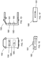
- the blank insert 150, 250, 350, 2170 may include a front facing surface (e.g. 160 of blank insert 150 of FIG. 1A ) configured to receive indicia or markings thereon.
- the blank insert 150, 250, 350, 2170 may include retention features (e.g. first and second apertures 170, 175 of the blank insert 150 of FIGs. 1A-F ) formed therein.
- the first and second apertures 170, 175 are each adapted and configured to receive an identification icon (e.g. identification icon 180, 185 of FIGs. 1C-F).
- FIGs. 1C-F , 2C-F , 3A-C and the following description include some non-limiting examples of types and sizes of identification icons that may be attached to the blank insert 150, 250, 350, 2170.
- the first aperture 170 is adapted and configured to receive a first identification icon 180
- the second aperture 175 is adapted and configured to receive a second identification icon 185 upon which are disposed various indicia or markings for purposes of identification.
- the first and second identification icons 180, 185 are sized so that the entire identification icon does not extend beyond the opposing side walls of blank insert 150.
- the first identification icon 180 includes a retention tab 181 that extends from the rear facing surface of the identification icon 180.
- the retention tab 181 assists in holding the identification icon 180 in place when the identification icon 180 is inserted into the blank insert 150.
- the second identification icon 185 includes a similar retention tab 183 as the retention tab 181 of the first identification icon 180.
- first identification icon 180 and the second identification icon 185 may be interchangeable.
- first and second identification icons 180, 185 may be removed from the first and second apertures 170, 175 formed in the blank insert 150, and replaced with other identification icons (not shown).
- the first and second identification icons 180, 185 may be flush with the front facing surface 160 of blank insert 150.
- the first and second identification icons may be received by the first and second apertures of the blank insert, respectively, or another type of retention feature on the blank insert, so that the first and second identification icons are at least partially raised from the front facing surface of the blank insert.
- the first and second identification icons may be recessed relative to the front facing surface of the blank insert.
- the first and second identification icons 180, 185 allow for additional information, such as marking and indicia, to be provided on the data communication station thereby enhancing the functionality of the blank insert 150.
- Each of the first and second identification icons 180, 185 may include markings or indicia (e.g. illustration, picture, letter, color, symbol, pattern, number, etc.) for purposes of identification and/or to convey information.
- the additional information may supplement the information that may be presented on the data communication station at another location such as, but not limited to, information that may be presented on the connector housing insert or cabling, and may be of use to any number of individuals such as, but not limited to, an end user, an information technology technician, a data communications contractor, etc.
- the first and second identification icons 180, 185 may include identifying information related to the current use of connectivity interfaces in a data communication station, and/or a future use of a connector housing insert and respective connectivity interface that may replace the blank insert 150.
- at least one of the first and second identification icons 180, 185 may include identifying information related to the data communication station and/or connectivity interface(s) (e.g. connector(s), port(s), jack(s), outlet(s), and the like) within the station such as, but not limited to, a specific color icon to identify the station as a 10GBASE-T Ethernet station, a phone or computer illustration to identify the purpose of a connectivity interface within the station, the location, and the like.
- at least one of the first and second identification icons 180, 185 may include identifying information related to the data communication station identification within the building, installation use, and/or maintenance information of the data communications infrastructure.
- the front facing surface 160 of blank insert 150 includes two apertures 170, 175 formed therein; however, in other embodiments, as is understood by one of ordinary skill in the art, the front facing surface of the blank insert may include any number of apertures formed therein (e.g. one, two, three, four, etc.), each such aperture being configured to receive an identification icon upon which indicia may be disposed as described above.
- the first and second apertures 170, 175 are generally rectangular-shaped and configured to receive generally rectangular-shaped identification icons 180, 185; however, as is understood by one of ordinary skill in the art, the identification icons 180, 185 may be any suitable size, shape, or orientation, and the corresponding apertures may be configured accordingly.
- the identification icon may extend beyond the opposing sidewalls of the blank insert and extend across at least some portion of the front facing surface of the blank insert.
- identification icons may be smaller than the front facing surface of the blank insert, being just large enough to add a color spot, or other such indicator, on the blank insert.
- the apertures 170, 175 formed in the blank insert are adapted and configured to receive the respective identification icon 180, 185, but it will be understood by one of ordinary skill in the art that the apertures 170, 175 formed therein are only an example of one type of retention feature, and in alternative embodiments, other types of retention features may be included on the blank insert to engage with the respective identification icons, such as but not limited to, the types of retention features shown in FIGs. 4A-C , 5A-H , 6A-I and described below.
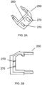
- FIGs. 2A-F an alternate exemplary embodiment of a blank insert 250 and respective identification icons are shown.
- the blank insert 250 and respective identification icons 280, 285 are substantially similar to the blank insert 150 and respective identification icons 180, 185 illustrated in FIGs. 1A-F and discussed above, except for the following additional features.
- the first and second identification icons 280, 285 are larger than the first and second identification icons 180, 185 (see FIG. 1C ). More specifically, the first and second identification icons 280, 285 extend across at least a portion of the front facing surface 260 of the blank insert 250. As such, the first and second identification icons 280, 285 are at least partially raised from the front facing surface 260 of the blank insert 250.
- the larger size of the first and second identification icons 280, 285 permits more indicia (e.g. illustration, picture, letter, color, symbol, pattern, number, etc.) to be marked on the identification icons than the smaller first and second identification icons 180, 185 (see FIG. 1C ). Thus, more information may be provided on the data communication station (not shown).
- the first and second identification icons 280, 285 may be of any suitable shape, size, or orientation. In some embodiments, the first identification icon 280 and the second identification icon 285 may be interchangeable. In addition, the first identification icon 280 and the second identification icon 285 may be removed from the first and second apertures 270, 275 and replaced with other identification icons having different identification markings or indicia (not shown). In another exemplary embodiment, identification icons of different sizes may be attached to the blank insert 250 of the data communication station. For example, the identification icon 180 (see FIG. 1C ) may be attached to the first aperture 270 formed in the blank insert, and the identification icon 285 (see FIG. 2C ) may be attached to the second aperture 275 formed in the blank insert.
- FIGs. 3A-C an alternate exemplary embodiment of a blank insert 350 is shown, the blank insert 350 being disposed in a data communication station 300, such as a wall plate.
- the blank insert 350 is substantially similar to the blank insert 150 illustrated in FIGs. 1A-F and discussed above, but for the following additional features.
- the first and second identification icons 380, 385 are larger than the first and second identification icons 180, 185 (see FIG. 1C ), and larger than the first and second identification icons 280, 285 (see Fig. 2C ). More specifically, the first identification icon 380 extends across and beyond the sides and the top of the front facing surface 360 of the blank insert 350, and the second identification icon 385 extends across and beyond the sides and the bottom of the front facing surface 360 of the blank insert 350. As such, the first and second identification icons 380, 385 are at least partially raised from the front facing surface 360 of the blank insert 350. The larger size of the first and second identification icons 380, 385 allows more markings or indicia (e.g.
- the first and second identification icons 380, 385 may be of any suitable shape, size, or orientation. In some embodiments, the first identification icon 380 and the second identification icon 385 may be interchangeable. In addition, the first identification icon 380 and the second identification icon 385 may be removed from the first and second apertures formed in the blank insert 350 and replaced with other identification icons having different identification markings or indicia (not shown). In another exemplary embodiment, identification icons of different sizes may be attached to the blank insert 350 of the data communication station 300. For example, the identification icon 180 (see FIG. 1C ) or the identification icon 280 (see FIG. 2C ) may be attached to the first aperture formed in the blank insert 350, and the identification icon 385 (see FIG. 3A ) may be attached to the second aperture formed in the blank insert 350.
- a connector housing insert 725 may include a connectivity interface 726 and a retention feature such as an aperture 770 formed therein.
- the aperture 770 formed in the connector housing insert 725 is adapted and configured to receive any of the identification icons 180, 185, 280, 285, 380, 385 (see FIGs. 1A-F , 2A-F , 3A-C ).
- any of the different-sized identification icons described above in relation to a blank insert may also be adapted and configured to attach to a connector housing insert (e.g. connector housing insert 725 of FIGs. 4A-B ) in substantially the same or similar way as the identification icons attach to the blank inserts.
- FIGs. 4A-C show another non-limiting exemplary embodiment of an identification icon 790 that may attach to the connector housing insert 725.
- the identification icon 790 may include a front facing surface 792 and a back surface 794.
- the front facing surface 792 is adapted and configured to receive indicia (e.g. illustration, picture, letter, color, words, symbol, pattern, number, etc.).
- the back surface 794 may include a retention tab 791 that extends from the back surface 794 in a rearward direction, the retention tab 791 being configured to attach the identification icon 790 to the connector housing insert 725.
- the retention tab 791 is adapted and configured to be inserted into the aperture 770 formed in the connector housing insert 725, and be engaged with the connector housing insert 725 by a snap-fit engagement. Similar snap-fit engagement may permit the coupling of the identification icons 180, 185, 280, 285, 380, 385 having retention tabs 181, 281, 381, respectively, as shown in FIGs. 1E-F , 2E-F and 3B-C , respectively, to the aperture 770 formed in the connector housing insert 725. Furthermore, the identification icon 790 may be removed from the connector housing insert 725 and be replaced with another identification icon (not shown).
- the identification icons 180, 185, 280, 285, 380, 385 and 790 may be composed of any suitable material.
- the identification icons 180, 185, 280, 285, 380, 385 and 790 are plastic.
- the identification icons may be metal, paper, card stock, a label, etc.
- the identification icons 180, 185, 280, 285, 380, 385 and 790 may include indicia (e.g. illustration, picture, letter, color, words, symbol, pattern, number, etc.) embedded on the front surface thereof, and/or may be configured to receive markings directly thereon with a pencil, pen, marker, other writing device, print device, such as but not limited to, a printer, label maker, etc.
- indicia may be molded into the identification icons 180, 185, 280, 285, 380, 385 and 790.
- the identification icons 180, 185, 280, 285, 380, 385 and 790 may be any suitable shape, size, or orientation.
- the aperture 770 formed in the connector housing insert 725 is only one type of retention feature which may be used and, in alternative embodiments, other types, shapes and sizes of retention features may be included on the connector housing insert to engage with the respective identification icon.
- the identification icon 790 allows for additional information to be provided on the data communication station (such as data communication station 300 shown in FIG. 3A ), thereby enhancing the functionality of the connector housing insert 725.
- the identification icon 790 may include indicia (e.g. illustration, picture, letter, color, words, symbol, pattern, number, etc.) for purposes of identification and/or to convey information.
- the additional information may supplement the information that may be presented at another location on the data communication station.
- the information may be of use to any number of individuals, such as but not limited to, an end user, an information technician, a data communications contractor, etc.
- the identification icon 790 may include identifying information related to the current use of the connectivity interface 726.
- the identification icon 790 may include identifying information related to the respective data communication station (e.g. data communication station 300 shown in FIG. 3A ). In yet another non-limiting example, the identification icon 790 may include identifying information related to the data communication station, identification within the building, installation use, and/or maintenance of the data communications infrastructure.
- the front facing surface 727 of the connector housing insert 725 includes one aperture 770 formed therein to receive an identification icon; however, in other embodiments, the connector housing insert may include any number of apertures (e.g. one, two, three, four, etc.) formed therein or other types of retention features, each aperture or other type of retention feature being configured to receive or attach an identification icon.
- the identification icon 790 attaches to the connector housing insert 725; however, in other embodiments, the identification icon 790 may be adapted and configured to be inserted into any of the apertures formed in a blank insert, such as but not limited to the apertures 170, 175 formed in the blank insert 150 (see FIGs. 1A-B ) and the apertures 270, 275 formed in the blank insert 250 (see FIGs. 2A-B ).
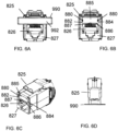
- FIGs. 5A-H show another non-limiting exemplary embodiment of a connector housing insert 825 and an identification icon 890.
- the connector housing insert 825 may include a connectivity interface 826, a recess 885 formed therein, and one or more retention features, such as flanges 880.
- the flanges 880 are adapted and configured to extend from the connector housing insert 825 from opposing sides 882, 884 of the recess 885 formed in the connector housing insert 825.
- another side 886 of the recess 885 formed in the connector housing insert 825 may include a slot 887.
- the recess 885 formed in the connector housing insert 825 is adapted and configured to receive the identification icon 890.
- the identification icon 890 may include a front facing surface 892 and a back surface 894.
- the front facing surface 892 is adapted and configured to receive indicia (e.g. illustration, picture, letter, color, words, symbol, pattern, number, etc.).
- the identification icon 890 is adapted and configured to be inserted into the recess 885 formed in the connector housing insert 825, and be engaged with the connector housing insert 825 by a snap-fit engagement. More specifically, the flanges 880 of the connector housing insert 825 assist in retaining the identification icon 890 within the recess 885.
- the identification icon 890 is sized so that the entire identification icon fits within the recess 885.
- the identification icon 890 may be removed from the connector housing insert 825 and be replaced with another identification icon (not shown).
- a tool 896 such as but not limited to a paperclip, may be used. That is, a portion of the tool 896 may be inserted into the slot 887 behind the identification icon 890, and push on the back surface 894 of the identification icon 890 to disengage the identification icon 890 from the connector housing insert 825.
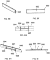
- FIGs. 6A-I shows an alternate exemplary embodiment of an identification icon 990.
- the identification icon 990 is substantially similar to the identification icon 890 illustrated in FIGs. 5A-H and discussed above, except for the following additional features.
- the identification icon 990 is larger than the identification icon 890 (see FIGs. 5A-H ). More specifically, the identification icon 990 extends across at least a portion of the front facing surface 827 of the connector housing insert 825. As such, the identification icon 990 is at least partially raised from the front facing surface 827 of the connector housing insert 825. The larger size of the identification icon 990 permits more indicia (e.g. illustration, picture, letter, color, symbol, pattern, number, etc.) to be marked on the front facing surface 992 of the identification icon 990 than the small identification icon 890 (see FIGs. 5A-H ). Thus, more information may be provided on the identification icon 990.
- indicia e.g. illustration, picture, letter, color, symbol, pattern, number, etc.
- the back surface 994 of the identification icon 990 may include a retention tab 991 that extends from the back surface 994 in a rearward direction.
- the retention tab 991 may include opposing first and second ends 998 having a middle portion 995 disposed therebetween. Furthermore, the retention tab 991 bows inward towards the back surface 994 of the identification icon 990.
- the retention tab 991 is adapted and configured to be inserted into the recess 885 formed in the connector housing insert 825, and engaged with the connector housing insert 825 by a snap-fit engagement. More specifically, when the identification icon 990 is attached to the connector housing insert 825, the opposing first and second ends 998 of the retention tab 991 fit under the flanges 880 of the connector housing insert 825. As such, the flanges 880 of the connector housing insert 825 engage the opposing first and second ends 998 of the identification icon 990, thereby retaining the retention tab 991 within the recess 885.
- the identification icon 890, 990 may be composed of any suitable material.
- the identification icon 890, 990 is plastic.
- the identification icon may be metal, paper, card stock, a label, etc.
- the identification icon 890, 990 may include indicia (e.g. illustration, picture, letter, color, words, symbol, pattern, number, etc.) embedded on the front surface thereof, and/or may be configured to receive markings directly thereon with a pencil, pen, marker, other writing device, print device, such as but not limited to, a printer, label maker, etc.
- indicia may be molded into the identification icon 890, 990.
- the identification icon 890, 990 may be any suitable shape, size, or orientation.
- the recess 885 and the flanges 880 formed in the connector housing insert 825 are only one type of retention feature which may be used and, in alternative embodiments, other types, shapes and sizes of retention features may be included on the connector housing insert to engage with the respective identification icon.
- the identification icon 890, 990 allows for additional information to be provided on the respective data communication station (such as data communication station 300 shown in FIG. 3A ), thereby enhancing the functionality of the connector housing insert 825.
- the identification icon 890, 990 may include indicia (e.g. illustration, picture, letter, color, words, symbol, pattern, number, etc.) for purposes of identification and/or to convey information.
- the additional information may supplement the information that may be presented at another location on the data communication station.
- the information may be of use to any number of individuals, such as but not limited to, an end user, an information technician, a data communications contractor, etc.
- the identification icon 890, 990 may include identifying information related to the current use of the connectivity interface 826. In another non-limiting example, the identification icon 890, 990 may include identifying information related to the respective data communication station (such as data communication station 300 shown in FIG. 3A ). In yet another non-limiting example, the identification icon 890, 990 may include identifying information related to the data communication station identification within the building, installation use, and/or maintenance of the data communications infrastructure.
- the front facing surface 827 of the connector housing insert 825 includes one recess 885 formed therein; however, in other embodiments, the connector housing insert may include any number of recesses (e.g. one, two, three, four, etc.) formed therein or other types of retention features, each recess or other type of retention feature being configured to receive or attach an identification icon.
- the connector housing insert may include any number of recesses (e.g. one, two, three, four, etc.) formed therein or other types of retention features, each recess or other type of retention feature being configured to receive or attach an identification icon.
- the identification icon 890, 990 attaches to the connector housing insert 825; however, in other embodiments, the identification icon 890, 990 may be adapted and configured to be attached to a blank insert.
- the identification icon 890, 990 may be of any suitable shape, size, or orientation (see FIGs. 5A-H , 6A-I ). In some embodiments, the identification icons 890, 990 may be interchangeable. In addition, the identification icon 890, 990 may be disengaged from the connector housing insert 825 and replaced with another identification icon having different identification markings or indicia (not shown). In another exemplary embodiment, an identification icon of a different size may be attached to the connector housing insert 825.
- the connector housing inserts 325, 335 may be configured accordingly to retain an identification icon, such as identification icon 790 (see FIGs. 4A-C ) or identification icon 890, 990 (see FIGs. 5A-H , 6A-I ).
- any of the identification icons described herein may vary based on the type of data communication station, the number of connector housing inserts and/or connectivity interfaces and/or blank inserts in the data communication station, the number of identification icons used in the data communication station, space availability to accommodate the identification icons, application requirements, etc.
- a data communication station 2000 may include one or more blank inserts 2170 adapted and configured to receive one or more identification icons (e.g. 2290), as described in detail above; and, the data communication station 2000 may also include one or more connector housing inserts 2125, 2135 adapted and configured to receive one or more other identification icons such as identification icons 180, 185, 280, 285, 380, 385, 790, 890 and 990 (see FIGs. 1C-F , 2C-F , 3A-C , 4A-C , 5A-H , 6A-I ) described in detail above.
- identification icons 180, 185, 280, 285, 380, 385, 790, 890 and 990 see FIGs. 1C-F , 2C-F , 3A-C , 4A-C , 5A-H , 6A-I ) described in detail above.
- the data communication station 2000 may include one or more identification icons 2300, 2400 that may be inserted and attached directly to a wall plate 2010.
- each of the one or more identification icons 2300, 2400 is adapted and configured to be in registered alignment with an aperture or apertures formed in the wall plate 2010.
- retention tabs 2310 disposed at the rear surface of identification icons 2300, 2400 may be used to attach the identification icons 2300, 2400 to the wall plate 2010, as shown in FIGs. 7A-C .
- identification icons 2300, 2400 may be structurally similar to identification icons 180, 185, 280, 285, 380, 385, 790, 890 and 990 (see FIGs. 1C-F , 2C-F , 3A-C , 4A-C , 5A-H , 6A-I ) with retention tabs extending from the rearward surface.
- identification icons 2300, 2400 may be sufficiently large in size to be comprised of a transparent front window portion or cover 2320 behind which is an inserted label insert 2330 (e.g. a strip of paper or plastic) upon which may be disposed markings or indicia.
- identification icons 2300, 2400 may include various forms of retention tabs 2310 at opposing ends or elsewhere that extend rearward and are configured to be received by apertures in the front face of wall plate 2010.
- identification icons 180, 185, 280, 285, 380, 385, 790, 890 and 990 may be comprised of a transparent window or cover, similar to window or cover 2320, and configured to receive an insertable label, such as label insert 2330, and upon which informative or identifying markings or indicia may be printed or disposed.
- the identification icons 2300, 2400 may be any suitable shape, size, or orientation.
- the connector housing inserts each include a connectivity interface, the connectivity interface configured to receive an RJ-45 connector.
- the connectivity interface may be used to receive other connectors, including but not limited to, other registered jacks (e.g. RJ-11, etc.), various category connectors (e.g. Category 6, Category 6A), S-Video adapters, F-Connectors, binding post connectors, banana jack connectors, stereo adapters, RCA connectors, BNC connectors, shielded connectors, USB, HDMI, DisplayPort and any other such connectors now or hereafter known.
- wall plates are shown to receive various inserts.
- other types of data communication stations such as wall plates, patch panels, patch blocks etc., variously configured to receive other types and shapes of inserts may be used.
- the respective data communication stations may include any number of apertures formed therein, and the apertures formed in the respective data communication stations may be arranged in various configurations.
Landscapes
- Physics & Mathematics (AREA)
- General Physics & Mathematics (AREA)
- Engineering & Computer Science (AREA)
- Theoretical Computer Science (AREA)
- Optics & Photonics (AREA)
- Connector Housings Or Holding Contact Members (AREA)
- Details Of Connecting Devices For Male And Female Coupling (AREA)
- Mobile Radio Communication Systems (AREA)
Applications Claiming Priority (4)
| Application Number | Priority Date | Filing Date | Title |
|---|---|---|---|
| US201562134905P | 2015-03-18 | 2015-03-18 | |
| US15/070,578 US10151890B2 (en) | 2015-03-18 | 2016-03-15 | Data communication port insert configurable with indicia to customize data communication station labeling and identification |
| PCT/US2016/022592 WO2016149332A1 (en) | 2015-03-18 | 2016-03-16 | Data communication port insert configurable with indicia to customize data communication station labeling and identification |
| EP16765633.9A EP3271971B1 (de) | 2015-03-18 | 2016-03-16 | Mit markierungen konfigurierbarer datenkommunikationsporteinsatz zur anpassung von datenkommunikationsstationsetikettierung und -identifizierung |
Related Parent Applications (2)
| Application Number | Title | Priority Date | Filing Date |
|---|---|---|---|
| EP16765633.9A Division EP3271971B1 (de) | 2015-03-18 | 2016-03-16 | Mit markierungen konfigurierbarer datenkommunikationsporteinsatz zur anpassung von datenkommunikationsstationsetikettierung und -identifizierung |
| EP16765633.9A Division-Into EP3271971B1 (de) | 2015-03-18 | 2016-03-16 | Mit markierungen konfigurierbarer datenkommunikationsporteinsatz zur anpassung von datenkommunikationsstationsetikettierung und -identifizierung |
Publications (3)
| Publication Number | Publication Date |
|---|---|
| EP4239807A2 true EP4239807A2 (de) | 2023-09-06 |
| EP4239807A3 EP4239807A3 (de) | 2023-10-18 |
| EP4239807B1 EP4239807B1 (de) | 2025-10-15 |
Family
ID=56919453
Family Applications (2)
| Application Number | Title | Priority Date | Filing Date |
|---|---|---|---|
| EP16765633.9A Active EP3271971B1 (de) | 2015-03-18 | 2016-03-16 | Mit markierungen konfigurierbarer datenkommunikationsporteinsatz zur anpassung von datenkommunikationsstationsetikettierung und -identifizierung |
| EP23182685.0A Active EP4239807B1 (de) | 2015-03-18 | 2016-03-16 | Mit markierungen konfigurierbarer datenkommunikationsporteinsatz zur anpassung der etikettierung und identifizierung von datenkommunikationsstationen |
Family Applications Before (1)
| Application Number | Title | Priority Date | Filing Date |
|---|---|---|---|
| EP16765633.9A Active EP3271971B1 (de) | 2015-03-18 | 2016-03-16 | Mit markierungen konfigurierbarer datenkommunikationsporteinsatz zur anpassung von datenkommunikationsstationsetikettierung und -identifizierung |
Country Status (5)
| Country | Link |
|---|---|
| US (2) | US10151890B2 (de) |
| EP (2) | EP3271971B1 (de) |
| CA (1) | CA2980144C (de) |
| MX (1) | MX2017011912A (de) |
| WO (1) | WO2016149332A1 (de) |
Families Citing this family (7)
| Publication number | Priority date | Publication date | Assignee | Title |
|---|---|---|---|---|
| JP1604551S (de) * | 2017-07-20 | 2018-05-21 | ||
| JP1604074S (de) * | 2017-07-20 | 2018-05-21 | ||
| CN111417995A (zh) | 2017-11-28 | 2020-07-14 | 康普技术有限责任公司 | 用于识别电信部件的标记和方法 |
| MX2020010032A (es) * | 2018-03-29 | 2020-10-14 | Commscope Technologies Llc | Marcas distintivas y metodo para identificar componentes de telecomunicaciones. |
| USD916044S1 (en) | 2018-10-19 | 2021-04-13 | Commscope Technologies Llc | Telecommunications enclosure |
| USD1073615S1 (en) * | 2020-09-08 | 2025-05-06 | Aces Electronics Co., Ltd. | Electrical connector |
| US20240346959A1 (en) * | 2023-04-11 | 2024-10-17 | Jensen Enterprises, Inc. | Utility Access Box Lid Labeling System and Methods |
Family Cites Families (132)
| Publication number | Priority date | Publication date | Assignee | Title |
|---|---|---|---|---|
| US1930610A (en) | 1933-02-20 | 1933-10-17 | Pass & Seymour Inc | Card holder |
| US1975690A (en) * | 1933-03-30 | 1934-10-02 | Arrow Hart & Hegeman Electric | Illuminated sign |
| US2431999A (en) | 1944-07-25 | 1947-12-02 | Glenn L Martin Co | Electrical connector block |
| US2515820A (en) | 1945-10-15 | 1950-07-18 | George P R Clark | Luminous display unit |
| US2549419A (en) | 1946-11-15 | 1951-04-17 | John X J Callahan | Multiplex laminated poster |
| US2625759A (en) | 1951-05-07 | 1953-01-20 | Koepke William Frederick | Electric outlet circuit indicator |
| US2710382A (en) * | 1954-04-06 | 1955-06-07 | Joseph P Fitzpatrick | Covers for electric wall receptacles |
| US3438536A (en) | 1966-11-29 | 1969-04-15 | Heinemann Electric Ltd | Removable covers |
| US3989338A (en) | 1974-11-08 | 1976-11-02 | Gosser Robert B | Push-pin assembly method and construction |
| US4293173A (en) * | 1978-02-16 | 1981-10-06 | Armstrong Cork Company | Electrical outlet insulation system |
| US4282591A (en) | 1979-03-22 | 1981-08-04 | Andreuccetti Ilio A | Light control and indicating device |
| US4479317A (en) | 1982-09-27 | 1984-10-30 | Hanna Ivan E | Electrical circuit marking identification plate |
| US4707564A (en) | 1986-03-27 | 1987-11-17 | Gonzales Arturo E F | Message cover for electrical wall switches |
| US4780573A (en) | 1986-06-24 | 1988-10-25 | Own Joseph K M | Switch/socket cover |
| US4743206A (en) * | 1986-11-10 | 1988-05-10 | Karl Imhoff | Child-safe outlet plate |
| US4820193A (en) | 1988-04-04 | 1989-04-11 | Thomas & Betts Corporation | Panel mounted electrical connector including means for providing an indication of correct conductor termination |
| US5106325A (en) | 1990-01-19 | 1992-04-21 | Leviton Manufacturing Co. Inc. | Modular higher density communications coupling system |
| US5051870A (en) | 1990-06-11 | 1991-09-24 | Companion John A | Electronic socket attachment method and identification system |
| US5212899A (en) | 1991-06-27 | 1993-05-25 | Gerhard Fandreyer | Switch plate labelling assembly |
| JPH0533412A (ja) | 1991-07-27 | 1993-02-09 | Hiroshi Yagakinai | 建物における間仕切りの施工方法 |
| US5284363A (en) | 1991-08-15 | 1994-02-08 | Gar-Doc, Inc. | Multi-layer hinged label |
| US5156551A (en) | 1991-10-01 | 1992-10-20 | Reliance Comm/Tec Corporation | Front-facing line terminal block assembly |
| US5380045A (en) | 1992-05-22 | 1995-01-10 | Comann; Tyler K. | Method for identifying an object and the resulting structure |
| US5295869A (en) | 1992-12-18 | 1994-03-22 | The Siemon Company | Electrically balanced connector assembly |
| US5401193A (en) | 1993-02-10 | 1995-03-28 | Lo Cicero; Rae-Ann | Patch panel system |
| USD359475S (en) | 1994-02-23 | 1995-06-20 | Superior Modular Products Incorporated | Patch panel |
| US5594206A (en) | 1994-06-03 | 1997-01-14 | Hubbell Incorporated | Label cover construction and arrangement thereof on switch faceplate |
| US5538438A (en) | 1994-07-26 | 1996-07-23 | Ortronics, Inc. | RJ connector and cover therefor |
| USD366025S (en) | 1994-08-10 | 1996-01-09 | The Siemon Company | Panel yoke |
| US5611691A (en) | 1995-01-17 | 1997-03-18 | Serge A. Atlan | Modular construction kit using electronic control modules |
| US5632648A (en) | 1995-04-19 | 1997-05-27 | Dan-Chief Enterprise Co., Ltd. | Adapter fixing device |
| US5613874A (en) * | 1995-05-05 | 1997-03-25 | Ortronics Inc. | Snap-in designation strip for modular information management oulet |
| US6496884B1 (en) | 1995-05-05 | 2002-12-17 | Nec Corporation | Microcomputer system with color coded components |
| US5769647A (en) | 1995-11-22 | 1998-06-23 | The Siemon Company | Modular outlet employing a door assembly |
| US5575665A (en) | 1995-12-01 | 1996-11-19 | Superior Modular Products Incorporated | Patch panel with hinged tie bar |
| US5675125A (en) | 1996-02-12 | 1997-10-07 | American Tack & Hardware Co., Inc. | Screwless outlet box covering |
| US5836786A (en) | 1996-05-21 | 1998-11-17 | The Whitaker Corporation | Patch panel having snap together construction |
| US5765698A (en) | 1996-09-04 | 1998-06-16 | Hubbell Incorporated | Panel assembly with angularly oriented hinges |
| JPH10172362A (ja) | 1996-12-11 | 1998-06-26 | Yazaki Corp | ケーブルラベル及びその貼着方法並びに電源接続部 |
| USD411514S (en) | 1997-07-24 | 1999-06-29 | The Siemon Company | Patch panel |
| DE19742456C2 (de) | 1997-09-26 | 2001-06-07 | Telefunken Microelectron | Verfahren zur Kennzeichnung von Gehäusen |
| US5975962A (en) | 1998-02-20 | 1999-11-02 | Laukonis; Robert | Network shelf system |
| US5983539A (en) | 1998-03-16 | 1999-11-16 | Martin; Brian | Tag lock |
| USD411515S (en) | 1998-04-08 | 1999-06-29 | The Siemon Company | Patch panel |
| US6089892A (en) | 1998-04-27 | 2000-07-18 | Haworth, Inc. | Telecommunications cabling arrangement |
| US6537106B1 (en) | 1998-06-05 | 2003-03-25 | Adc Telecommunications, Inc. | Telecommunications patch panel with angled connector modules |
| US6053764A (en) | 1998-06-30 | 2000-04-25 | Lucent Technologies Inc. | Patch panel and interlocking module |
| US6371793B1 (en) | 1998-08-24 | 2002-04-16 | Panduit Corp. | Low crosstalk modular communication connector |
| US6026605A (en) | 1998-10-28 | 2000-02-22 | Tippett; Nancy J. | Switch plate picture frame assembly |
| US6086415A (en) | 1998-10-29 | 2000-07-11 | Hubbell Incorporated | High density modular patch panel |
| US6282826B1 (en) | 1999-01-27 | 2001-09-04 | James R. Richards | Protective holder and method of using same |
| US6215067B1 (en) | 1999-04-29 | 2001-04-10 | Surtec Industries Inc. | Communication line connecting box with pivoted cover |
| US6337836B1 (en) | 1999-06-01 | 2002-01-08 | Arthur F. Eidelson | Programmable electronic label |
| US6172301B1 (en) | 1999-07-14 | 2001-01-09 | Hubbell Incorporated | Receptacle faceplate |
| US6245998B1 (en) | 1999-10-27 | 2001-06-12 | Avaya Technology Corp. | Cable management assembly for equipment racks |
| US6520544B1 (en) | 2000-01-10 | 2003-02-18 | Moore North America, Inc. | Radio frequency labels on reusable containers |
| WO2001052364A1 (en) | 2000-01-14 | 2001-07-19 | Panduit Corp. | Low crosstalk modular communication connector |
| US6358080B1 (en) | 2000-05-23 | 2002-03-19 | Avaya Technology Corp. | Snap-in module system |
| US6332795B1 (en) | 2000-05-23 | 2001-12-25 | Avaya Technology Corp. | Hinged connection system |
| US6421941B1 (en) | 2000-06-30 | 2002-07-23 | Adc Telecommunications, Inc. | Designation window |
| US7161556B2 (en) | 2000-08-07 | 2007-01-09 | Color Kinetics Incorporated | Systems and methods for programming illumination devices |
| US6347715B1 (en) | 2000-09-25 | 2002-02-19 | Hubbell Incorporated | Patch panel assembly |
| US6722563B1 (en) | 2000-10-17 | 2004-04-20 | Pitney Bowes Inc. | Method for printing a label pair with information-based indicia program (IBIP) indicia |
| US6461189B1 (en) | 2000-12-21 | 2002-10-08 | Compaq Information Technologies Group, L.P. | Connector map |
| US6831569B2 (en) | 2001-03-08 | 2004-12-14 | Koninklijke Philips Electronics N.V. | Method and system for assigning and binding a network address of a ballast |
| US6793524B2 (en) * | 2001-03-30 | 2004-09-21 | Adc Telecommunications, Inc. | Multimedia outlet with protective cover |
| US6814625B2 (en) * | 2001-04-10 | 2004-11-09 | Cinch Connectors, Inc. | Electrical connector |
| US6761583B2 (en) | 2001-06-01 | 2004-07-13 | Agilent Technologies, Inc. | Modular system interface apparatus |
| ITGE20010019U1 (it) | 2001-06-20 | 2002-12-20 | Grafoplast Spa | Tessere multiple a doppio spessore stampabili con stampante a trasferimento termico per la siglatura di componenti elettrotecnici e/o elettr |
| US6877218B2 (en) | 2001-06-21 | 2005-04-12 | Rauland-Borg Corporation | Hand tool for applying electrical connectors |
| US6642452B2 (en) | 2001-08-31 | 2003-11-04 | Iplate Technologies, Inc. | Lighted switch or outlet plate with labeling designation |
| US6478611B1 (en) | 2001-11-08 | 2002-11-12 | Hon Hai Precision Ind. Co., Ltd. | Electrical connector with visual indicator |
| US6599149B2 (en) | 2002-01-02 | 2003-07-29 | Surtec Industries, Inc. | Patch panel |
| US20030145945A1 (en) | 2002-02-06 | 2003-08-07 | Kennedy Patrick R. | Labeling assembly |
| US6752431B1 (en) | 2002-03-08 | 2004-06-22 | Ampersand Label, Inc. | Peel-back, re-sealable multi-ply label |
| US6718674B2 (en) | 2002-03-21 | 2004-04-13 | Panduit Corp. | Apparatus and system for identification labeling |
| KR200283068Y1 (ko) | 2002-03-22 | 2002-07-26 | 김동준 | 와이어 연결블록의 라벨홀더 고정구조 |
| US6786776B2 (en) | 2002-09-27 | 2004-09-07 | Leviton Manufacturing Co., Inc. | Electrical connector jack |
| JPWO2004042878A1 (ja) | 2002-11-05 | 2006-03-09 | 矢崎総業株式会社 | コネクタハウジング、コネクタハウジングのマーキング方法及びコネクタハウジングへの端子金具の挿入方法 |
| US6814624B2 (en) | 2002-11-22 | 2004-11-09 | Adc Telecommunications, Inc. | Telecommunications jack assembly |
| US7709072B2 (en) | 2002-12-20 | 2010-05-04 | Panduit Corp. | Adhesive pattern for a label system |
| JP2004239994A (ja) | 2003-02-04 | 2004-08-26 | Fuji Photo Film Co Ltd | コネクタ用表示具 |
| US6916211B2 (en) | 2003-02-20 | 2005-07-12 | Eric Charles Price | Electrical circuit breadboard |
| US7119708B2 (en) | 2003-04-11 | 2006-10-10 | Avaya Technology Corp | Apparatus and method for providing visual and hardware addressing information |
| US7112090B2 (en) | 2003-05-14 | 2006-09-26 | Panduit Corp. | High density keystone jack patch panel |
| US7400226B2 (en) | 2003-09-12 | 2008-07-15 | Simplexgrinnell Lp | Emergency lighting system with improved monitoring |
| US20060059757A1 (en) * | 2004-09-17 | 2006-03-23 | Illen Products Ltd. | Identifier tag assembly having peripheral frame |
| US7357249B1 (en) | 2004-10-18 | 2008-04-15 | Weber Warren D | Optical disc stacked removable label marketing system |
| US7424785B2 (en) | 2004-12-20 | 2008-09-16 | Emc Corporation | Label cassette for an electronics enclosure |
| US7404736B2 (en) | 2004-12-30 | 2008-07-29 | Panduit Corp. | Patch panel and strain relief bar assembly |
| US7672591B2 (en) | 2005-03-01 | 2010-03-02 | Soto Alexander I | System and method for a subscriber-powered network element |
| GB0504522D0 (en) | 2005-03-04 | 2005-04-13 | Tyco Electronics Amp Es Sa | Network connection sensing assembly |
| DE102006019144A1 (de) | 2005-05-24 | 2006-11-30 | Erco Leuchten Gmbh | Leuchte |
| USD542240S1 (en) | 2005-09-08 | 2007-05-08 | Leviton Manufacturing Co., Inc. | Patch panel |
| JP2007174750A (ja) | 2005-12-20 | 2007-07-05 | Furukawa Electric Co Ltd:The | ワイヤーハーネス外装品 |
| US7183487B1 (en) | 2006-01-31 | 2007-02-27 | Panduit Corp. | Stainless steel faceplates with labels |
| US7371107B2 (en) | 2006-03-29 | 2008-05-13 | Lotes Co., Ltd. | Electrical connector |
| KR200422110Y1 (ko) | 2006-04-24 | 2006-07-24 | 대은전자 주식회사 | 통신기기용 모듈러 패치패널 |
| US7740282B2 (en) * | 2006-05-05 | 2010-06-22 | Leviton Manufacturing Co., Inc. | Port identification system and method |
| US7581843B2 (en) | 2006-06-02 | 2009-09-01 | Joseph Stauner | Electrical fixture assembly adapted to be modified to comply to a power usage limit |
| US7343078B2 (en) | 2006-06-29 | 2008-03-11 | Commscope Solutions Properties, Llc | Patch panels with communications connectors that are rotatable about a vertical axis |
| US7479032B2 (en) | 2006-10-10 | 2009-01-20 | Adc Gmbh | Upgradeable telecommunications patch panel and method of upgrading same |
| US7722402B2 (en) | 2006-10-16 | 2010-05-25 | Tyco Electronics Corporation | Panel interface module which provides electrical connectivity between panel and shielded jacks |
| US7455548B2 (en) | 2006-10-19 | 2008-11-25 | Adc Telecommunication, Inc. | Rotatable connector modules with inverted jacks |
| US7335056B1 (en) | 2006-10-19 | 2008-02-26 | Adc Telecommunications, Inc. | RJ to RJ swing panel |
| US7427204B1 (en) * | 2006-10-30 | 2008-09-23 | Mangone Peter G | Dummy plug apparatus with unitary tag |
| US7674977B1 (en) * | 2006-12-12 | 2010-03-09 | Airtite Systems LLC | Wall outlet plate assembly |
| US7488205B2 (en) | 2006-12-13 | 2009-02-10 | Commscope, Inc. Of North Carolina | Fixed angled patch panel |
| US8267714B2 (en) * | 2007-03-29 | 2012-09-18 | The Siemon Company | Modular connector with reduced termination variability and improved performance |
| US7585191B2 (en) | 2007-06-01 | 2009-09-08 | Telect Inc. | Intuitive labeling schemes for structured cabling solutions |
| US7565053B2 (en) * | 2007-06-05 | 2009-07-21 | Adc Telecommunications, Inc. | Fiber optic dust cap and dust plug with high power protection |
| CA2617853A1 (en) | 2008-01-11 | 2009-07-11 | Belden Cdt Canada Inc. | Patch panel labelling system |
| US7547227B1 (en) | 2008-04-21 | 2009-06-16 | Leviton Manufacturing Co., Inc. | Adhesive laminate label for a communication connector jack and communication connector jack including same |
| US7756380B2 (en) | 2008-07-31 | 2010-07-13 | Commscope, Inc. Of North Carolina | Hinged cable guide panel providing access to panel rear |
| US7722411B2 (en) | 2008-08-28 | 2010-05-25 | Leviton Manufacturing Co., Inc. | Voice and data patch panel having a bracket for structured wire enclosures |
| USD616374S1 (en) | 2008-09-30 | 2010-05-25 | Leviton Manufacturing Co., Inc. | Patch panel |
| US8028452B2 (en) | 2008-10-17 | 2011-10-04 | Leviton Manufacturing Co., Ltd. | Enhanced patch panel indicia system |
| AU2009200824A1 (en) | 2009-03-03 | 2010-09-23 | Tyco Electronics Services Gmbh | Consolidation point enclosure |
| WO2010114789A1 (en) | 2009-04-02 | 2010-10-07 | The Siemon Company | Telecommunications patch panel |
| EP2264497A1 (de) * | 2009-06-19 | 2010-12-22 | Corning Cable Systems LLC | Faseroptische Modulanordnung mit verbessertem Zugang and Beschriftung |
| US8643476B2 (en) * | 2009-06-29 | 2014-02-04 | Commscope, Inc. Of North Carolina | Dynamic labeling of patch panel ports |
| US8221157B2 (en) * | 2009-09-21 | 2012-07-17 | Ideal Industries, Inc. | Connector assemblies with integrated wiring diagrams and methods of using the same |
| DE102010009804A1 (de) * | 2010-03-01 | 2011-09-01 | Phoenix Contact Gmbh & Co. Kg | Elektrische Anschlussklemme |
| US8038456B1 (en) * | 2010-04-23 | 2011-10-18 | Leviton Manufacturing Co., Inc | Tamper prevention system having a shroud to partially cover a release mechanism |
| EP2400775B1 (de) | 2010-06-22 | 2014-01-15 | 3M Innovative Properties Co. | Trägerstruktur für Telekommunikationsbuchsen |
| DE202011000748U1 (de) * | 2011-03-31 | 2012-07-04 | Weidmüller Interface GmbH & Co. KG | Anschlussvorrichtung für einen elektrischen Leiter mit einer Markiervorrichtung |
| US8485834B2 (en) * | 2011-05-12 | 2013-07-16 | International Business Machines Corporation | Mitigating electromagnetic interference using dummy plugs |
| US8391663B2 (en) | 2011-05-24 | 2013-03-05 | Methode Electronics, Inc. | Rack cabling system |
| US8636222B2 (en) * | 2011-10-07 | 2014-01-28 | Kurt Vanderwel | Selectively concealable indicator systems and assemblies |
| US9223097B2 (en) * | 2012-01-31 | 2015-12-29 | Hewlett Packard Enterprise Development Lp | Connector indicia |
| US9058752B2 (en) * | 2012-09-12 | 2015-06-16 | Panduit Corp. | Flex mount terminal marker |
| US9196977B2 (en) * | 2013-07-30 | 2015-11-24 | Consert Inc. | Apparatus for use in wiring a multi-configurable electrical device during installation thereof at a point of operation |
-
2016
- 2016-03-15 US US15/070,578 patent/US10151890B2/en active Active
- 2016-03-16 CA CA2980144A patent/CA2980144C/en active Active
- 2016-03-16 EP EP16765633.9A patent/EP3271971B1/de active Active
- 2016-03-16 EP EP23182685.0A patent/EP4239807B1/de active Active
- 2016-03-16 WO PCT/US2016/022592 patent/WO2016149332A1/en not_active Ceased
- 2016-03-16 MX MX2017011912A patent/MX2017011912A/es unknown
-
2018
- 2018-08-31 US US16/119,851 patent/US10371902B2/en active Active
Also Published As
| Publication number | Publication date |
|---|---|
| WO2016149332A1 (en) | 2016-09-22 |
| EP3271971B1 (de) | 2023-08-09 |
| CA2980144A1 (en) | 2016-09-22 |
| EP3271971A1 (de) | 2018-01-24 |
| US20190004259A1 (en) | 2019-01-03 |
| CA2980144C (en) | 2023-09-05 |
| US10371902B2 (en) | 2019-08-06 |
| EP4239807A3 (de) | 2023-10-18 |
| EP4239807B1 (de) | 2025-10-15 |
| US20160276779A1 (en) | 2016-09-22 |
| MX2017011912A (es) | 2018-04-10 |
| US10151890B2 (en) | 2018-12-11 |
| EP3271971A4 (de) | 2018-11-14 |
Similar Documents
| Publication | Publication Date | Title |
|---|---|---|
| US10371902B2 (en) | Data communication port insert configurable with indicia to customize data communication station labeling and identification | |
| US20110189863A1 (en) | Break-away connection for in-flight entertainment system | |
| US7591667B2 (en) | Network connection sensing assembly | |
| CN202050511U (zh) | 智能型结构的布缆系统与其配线座 | |
| US9832542B2 (en) | Patch panel system and jack module attachment thereto | |
| ES2731679T3 (es) | Sistema de conexiones de comunicaciones | |
| US10522939B2 (en) | Cover assembly for a telecommunications connector | |
| EP2264497A1 (de) | Faseroptische Modulanordnung mit verbessertem Zugang and Beschriftung | |
| CN105068192B (zh) | 光纤连接器 | |
| US9966716B2 (en) | Adapter | |
| EP4737969A2 (de) | Faseroptische ablagesysteme | |
| CN101171723B (zh) | 可插接的无螺丝的线连接器系统 | |
| CN201926780U (zh) | 具有防误插识别信息的sc连接器组件及其sc插头 | |
| CN204391333U (zh) | 以一体式舌板固定金属间隔板的信号连接器 | |
| JP2939714B2 (ja) | コネクタ | |
| CN102759778B (zh) | 一种光连接器插头 | |
| US7874866B2 (en) | Labeling assembly | |
| CN101692515B (zh) | Sata连接器 | |
| JP2555357Y2 (ja) | 光レセプタクル | |
| CN101694909B (zh) | Sata连接器 | |
| CN212970405U (zh) | 兼容不同接收卡的hub板及led显示箱体 | |
| JP3145618U (ja) | 4チャネルコンパクト型プラグ着脱可能なトランシーバモジュールのケース構造 | |
| CN201699234U (zh) | Usb插槽连接器 | |
| CN205985640U (zh) | 可正反插的快速充电转接头 | |
| CN103427245A (zh) | 可插拔的接线装置和具有可插拔的接线装置的电子仪器 |
Legal Events
| Date | Code | Title | Description |
|---|---|---|---|
| PUAI | Public reference made under article 153(3) epc to a published international application that has entered the european phase |
Free format text: ORIGINAL CODE: 0009012 |
|
| STAA | Information on the status of an ep patent application or granted ep patent |
Free format text: STATUS: THE APPLICATION HAS BEEN PUBLISHED |
|
| AC | Divisional application: reference to earlier application |
Ref document number: 3271971 Country of ref document: EP Kind code of ref document: P |
|
| AK | Designated contracting states |
Kind code of ref document: A2 Designated state(s): AL AT BE BG CH CY CZ DE DK EE ES FI FR GB GR HR HU IE IS IT LI LT LU LV MC MK MT NL NO PL PT RO RS SE SI SK SM TR |
|
| PUAL | Search report despatched |
Free format text: ORIGINAL CODE: 0009013 |
|
| AK | Designated contracting states |
Kind code of ref document: A3 Designated state(s): AL AT BE BG CH CY CZ DE DK EE ES FI FR GB GR HR HU IE IS IT LI LT LU LV MC MK MT NL NO PL PT RO RS SE SI SK SM TR |
|
| RIC1 | Information provided on ipc code assigned before grant |
Ipc: H01R 24/64 20110101ALN20230912BHEP Ipc: H01R 13/443 20060101ALI20230912BHEP Ipc: H01R 13/46 20060101AFI20230912BHEP |
|
| STAA | Information on the status of an ep patent application or granted ep patent |
Free format text: STATUS: REQUEST FOR EXAMINATION WAS MADE |
|
| 17P | Request for examination filed |
Effective date: 20240129 |
|
| RBV | Designated contracting states (corrected) |
Designated state(s): AL AT BE BG CH CY CZ DE DK EE ES FI FR GB GR HR HU IE IS IT LI LT LU LV MC MK MT NL NO PL PT RO RS SE SI SK SM TR |
|
| GRAP | Despatch of communication of intention to grant a patent |
Free format text: ORIGINAL CODE: EPIDOSNIGR1 |
|
| STAA | Information on the status of an ep patent application or granted ep patent |
Free format text: STATUS: GRANT OF PATENT IS INTENDED |
|
| RIC1 | Information provided on ipc code assigned before grant |
Ipc: H01R 24/64 20110101ALN20250513BHEP Ipc: G09F 23/00 20060101ALI20250513BHEP Ipc: G09F 3/16 20060101ALI20250513BHEP Ipc: H01R 13/443 20060101ALI20250513BHEP Ipc: H01R 13/46 20060101AFI20250513BHEP |
|
| INTG | Intention to grant announced |
Effective date: 20250522 |
|
| GRAS | Grant fee paid |
Free format text: ORIGINAL CODE: EPIDOSNIGR3 |
|
| GRAA | (expected) grant |
Free format text: ORIGINAL CODE: 0009210 |
|
| STAA | Information on the status of an ep patent application or granted ep patent |
Free format text: STATUS: THE PATENT HAS BEEN GRANTED |
|
| AC | Divisional application: reference to earlier application |
Ref document number: 3271971 Country of ref document: EP Kind code of ref document: P |
|
| AK | Designated contracting states |
Kind code of ref document: B1 Designated state(s): AL AT BE BG CH CY CZ DE DK EE ES FI FR GB GR HR HU IE IS IT LI LT LU LV MC MK MT NL NO PL PT RO RS SE SI SK SM TR |
|
| P01 | Opt-out of the competence of the unified patent court (upc) registered |
Free format text: CASE NUMBER: UPC_APP_5979_4239807/2025 Effective date: 20250904 |
|
| REG | Reference to a national code |
Ref country code: GB Ref legal event code: FG4D Ref country code: CH Ref legal event code: F10 Free format text: ST27 STATUS EVENT CODE: U-0-0-F10-F00 (AS PROVIDED BY THE NATIONAL OFFICE) Effective date: 20251015 |
|
| REG | Reference to a national code |
Ref country code: DE Ref legal event code: R096 Ref document number: 602016093837 Country of ref document: DE |
|
| REG | Reference to a national code |
Ref country code: IE Ref legal event code: FG4D |
|
| REG | Reference to a national code |
Ref country code: NL Ref legal event code: MP Effective date: 20251015 |
|
| REG | Reference to a national code |
Ref country code: AT Ref legal event code: MK05 Ref document number: 1847886 Country of ref document: AT Kind code of ref document: T Effective date: 20251015 |
|
| PG25 | Lapsed in a contracting state [announced via postgrant information from national office to epo] |
Ref country code: NL Free format text: LAPSE BECAUSE OF FAILURE TO SUBMIT A TRANSLATION OF THE DESCRIPTION OR TO PAY THE FEE WITHIN THE PRESCRIBED TIME-LIMIT Effective date: 20251015 |
|
| PGFP | Annual fee paid to national office [announced via postgrant information from national office to epo] |
Ref country code: GB Payment date: 20260330 Year of fee payment: 11 |
|
| PG25 | Lapsed in a contracting state [announced via postgrant information from national office to epo] |
Ref country code: ES Free format text: LAPSE BECAUSE OF FAILURE TO SUBMIT A TRANSLATION OF THE DESCRIPTION OR TO PAY THE FEE WITHIN THE PRESCRIBED TIME-LIMIT Effective date: 20251015 |
|
| REG | Reference to a national code |
Ref country code: LT Ref legal event code: MG9D |
|
| PG25 | Lapsed in a contracting state [announced via postgrant information from national office to epo] |
Ref country code: NO Free format text: LAPSE BECAUSE OF FAILURE TO SUBMIT A TRANSLATION OF THE DESCRIPTION OR TO PAY THE FEE WITHIN THE PRESCRIBED TIME-LIMIT Effective date: 20260115 |
|
| PG25 | Lapsed in a contracting state [announced via postgrant information from national office to epo] |
Ref country code: AT Free format text: LAPSE BECAUSE OF FAILURE TO SUBMIT A TRANSLATION OF THE DESCRIPTION OR TO PAY THE FEE WITHIN THE PRESCRIBED TIME-LIMIT Effective date: 20251015 Ref country code: FI Free format text: LAPSE BECAUSE OF FAILURE TO SUBMIT A TRANSLATION OF THE DESCRIPTION OR TO PAY THE FEE WITHIN THE PRESCRIBED TIME-LIMIT Effective date: 20251015 Ref country code: HR Free format text: LAPSE BECAUSE OF FAILURE TO SUBMIT A TRANSLATION OF THE DESCRIPTION OR TO PAY THE FEE WITHIN THE PRESCRIBED TIME-LIMIT Effective date: 20251015 |
|
| PG25 | Lapsed in a contracting state [announced via postgrant information from national office to epo] |
Ref country code: RS Free format text: LAPSE BECAUSE OF FAILURE TO SUBMIT A TRANSLATION OF THE DESCRIPTION OR TO PAY THE FEE WITHIN THE PRESCRIBED TIME-LIMIT Effective date: 20260115 |
|
| PG25 | Lapsed in a contracting state [announced via postgrant information from national office to epo] |
Ref country code: IS Free format text: LAPSE BECAUSE OF FAILURE TO SUBMIT A TRANSLATION OF THE DESCRIPTION OR TO PAY THE FEE WITHIN THE PRESCRIBED TIME-LIMIT Effective date: 20260215 |
|
| PGFP | Annual fee paid to national office [announced via postgrant information from national office to epo] |
Ref country code: FR Payment date: 20260327 Year of fee payment: 11 |
|
| PG25 | Lapsed in a contracting state [announced via postgrant information from national office to epo] |
Ref country code: PT Free format text: LAPSE BECAUSE OF FAILURE TO SUBMIT A TRANSLATION OF THE DESCRIPTION OR TO PAY THE FEE WITHIN THE PRESCRIBED TIME-LIMIT Effective date: 20260216 |
|
| PG25 | Lapsed in a contracting state [announced via postgrant information from national office to epo] |
Ref country code: PL Free format text: LAPSE BECAUSE OF FAILURE TO SUBMIT A TRANSLATION OF THE DESCRIPTION OR TO PAY THE FEE WITHIN THE PRESCRIBED TIME-LIMIT Effective date: 20251015 |
|
| PG25 | Lapsed in a contracting state [announced via postgrant information from national office to epo] |
Ref country code: LV Free format text: LAPSE BECAUSE OF FAILURE TO SUBMIT A TRANSLATION OF THE DESCRIPTION OR TO PAY THE FEE WITHIN THE PRESCRIBED TIME-LIMIT Effective date: 20251015 |
|
| PG25 | Lapsed in a contracting state [announced via postgrant information from national office to epo] |
Ref country code: BG Free format text: LAPSE BECAUSE OF FAILURE TO SUBMIT A TRANSLATION OF THE DESCRIPTION OR TO PAY THE FEE WITHIN THE PRESCRIBED TIME-LIMIT Effective date: 20251015 |