EP4239336A1 - Procédé de fabrication d'une plaque de microtitrage dotée de revêtements à molécules de capture et plaque de microtitrage - Google Patents
Procédé de fabrication d'une plaque de microtitrage dotée de revêtements à molécules de capture et plaque de microtitrage Download PDFInfo
- Publication number
- EP4239336A1 EP4239336A1 EP22160018.2A EP22160018A EP4239336A1 EP 4239336 A1 EP4239336 A1 EP 4239336A1 EP 22160018 A EP22160018 A EP 22160018A EP 4239336 A1 EP4239336 A1 EP 4239336A1
- Authority
- EP
- European Patent Office
- Prior art keywords
- membrane
- segment
- carrier
- segments
- blot
- Prior art date
- Legal status (The legal status is an assumption and is not a legal conclusion. Google has not performed a legal analysis and makes no representation as to the accuracy of the status listed.)
- Granted
Links
- 238000000576 coating method Methods 0.000 title claims abstract description 33
- 238000004519 manufacturing process Methods 0.000 title claims description 4
- 238000005497 microtitration Methods 0.000 title 2
- 239000012528 membrane Substances 0.000 claims abstract description 242
- 238000000034 method Methods 0.000 claims abstract description 38
- 239000011248 coating agent Substances 0.000 claims abstract description 10
- 239000010410 layer Substances 0.000 claims description 125
- 239000000427 antigen Substances 0.000 claims description 50
- 102000036639 antigens Human genes 0.000 claims description 50
- 108091007433 antigens Proteins 0.000 claims description 50
- 239000012790 adhesive layer Substances 0.000 claims description 42
- 230000027455 binding Effects 0.000 claims description 24
- 238000004080 punching Methods 0.000 claims description 17
- 239000013610 patient sample Substances 0.000 claims description 15
- 230000000903 blocking effect Effects 0.000 claims description 14
- 101000946191 Galerina sp Laccase-1 Proteins 0.000 claims description 13
- 101100218337 Gibberella zeae (strain ATCC MYA-4620 / CBS 123657 / FGSC 9075 / NRRL 31084 / PH-1) aurL2 gene Proteins 0.000 claims description 13
- 101150017281 LAC2 gene Proteins 0.000 claims description 13
- 239000002313 adhesive film Substances 0.000 claims description 11
- 238000003672 processing method Methods 0.000 claims description 11
- 238000005520 cutting process Methods 0.000 claims description 6
- 239000000758 substrate Substances 0.000 claims description 6
- 238000000926 separation method Methods 0.000 claims description 5
- 238000003119 immunoblot Methods 0.000 description 10
- 238000012360 testing method Methods 0.000 description 9
- 238000011156 evaluation Methods 0.000 description 6
- 238000011534 incubation Methods 0.000 description 6
- 238000012545 processing Methods 0.000 description 6
- 238000002845 discoloration Methods 0.000 description 5
- 210000002966 serum Anatomy 0.000 description 5
- 102100028707 Homeobox protein MSX-1 Human genes 0.000 description 4
- 102100040615 Homeobox protein MSX-2 Human genes 0.000 description 4
- 101000985653 Homo sapiens Homeobox protein MSX-1 Proteins 0.000 description 4
- 101000967222 Homo sapiens Homeobox protein MSX-2 Proteins 0.000 description 4
- 101001047659 Homo sapiens Lymphocyte transmembrane adapter 1 Proteins 0.000 description 4
- 101150043187 LAX2 gene Proteins 0.000 description 4
- 101150100093 LAX3 gene Proteins 0.000 description 4
- 102100024034 Lymphocyte transmembrane adapter 1 Human genes 0.000 description 4
- 239000000853 adhesive Substances 0.000 description 4
- 230000001070 adhesive effect Effects 0.000 description 4
- 238000013019 agitation Methods 0.000 description 4
- 238000013459 approach Methods 0.000 description 4
- 101000575029 Bacillus subtilis (strain 168) 50S ribosomal protein L11 Proteins 0.000 description 3
- 102100035793 CD83 antigen Human genes 0.000 description 3
- 101000946856 Homo sapiens CD83 antigen Proteins 0.000 description 3
- 239000002318 adhesion promoter Substances 0.000 description 3
- 229920000139 polyethylene terephthalate Polymers 0.000 description 3
- 239000005020 polyethylene terephthalate Substances 0.000 description 3
- 230000001681 protective effect Effects 0.000 description 3
- 239000002516 radical scavenger Substances 0.000 description 3
- 230000011218 segmentation Effects 0.000 description 3
- 239000000126 substance Substances 0.000 description 3
- 102000002260 Alkaline Phosphatase Human genes 0.000 description 2
- 108020004774 Alkaline Phosphatase Proteins 0.000 description 2
- 101000592939 Bacillus subtilis (strain 168) 50S ribosomal protein L24 Proteins 0.000 description 2
- 208000016604 Lyme disease Diseases 0.000 description 2
- 108700023315 OspC Proteins 0.000 description 2
- 239000003153 chemical reaction reagent Substances 0.000 description 2
- 238000001514 detection method Methods 0.000 description 2
- 238000003745 diagnosis Methods 0.000 description 2
- 230000009871 nonspecific binding Effects 0.000 description 2
- 210000002381 plasma Anatomy 0.000 description 2
- 239000004033 plastic Substances 0.000 description 2
- 229920003023 plastic Polymers 0.000 description 2
- 238000002360 preparation method Methods 0.000 description 2
- 239000000523 sample Substances 0.000 description 2
- 239000007790 solid phase Substances 0.000 description 2
- QRXMUCSWCMTJGU-UHFFFAOYSA-L (5-bromo-4-chloro-1h-indol-3-yl) phosphate Chemical compound C1=C(Br)C(Cl)=C2C(OP([O-])(=O)[O-])=CNC2=C1 QRXMUCSWCMTJGU-UHFFFAOYSA-L 0.000 description 1
- QRXMUCSWCMTJGU-UHFFFAOYSA-N 5-bromo-4-chloro-3-indolyl phosphate Chemical compound C1=C(Br)C(Cl)=C2C(OP(O)(=O)O)=CNC2=C1 QRXMUCSWCMTJGU-UHFFFAOYSA-N 0.000 description 1
- 208000030090 Acute Disease Diseases 0.000 description 1
- 101100237207 Arabidopsis thaliana MS3 gene Proteins 0.000 description 1
- 208000023275 Autoimmune disease Diseases 0.000 description 1
- 241000894006 Bacteria Species 0.000 description 1
- 208000035143 Bacterial infection Diseases 0.000 description 1
- 241001148604 Borreliella afzelii Species 0.000 description 1
- 241000589969 Borreliella burgdorferi Species 0.000 description 1
- 241001148605 Borreliella garinii Species 0.000 description 1
- 108010040721 Flagellin Proteins 0.000 description 1
- 101000832767 Homo sapiens Disintegrin and metalloproteinase domain-containing protein 8 Proteins 0.000 description 1
- 206010020751 Hypersensitivity Diseases 0.000 description 1
- 101100181411 Medicago truncatula LAX4 gene Proteins 0.000 description 1
- 101100024551 Mus musculus Msx3 gene Proteins 0.000 description 1
- 239000000020 Nitrocellulose Substances 0.000 description 1
- 239000004677 Nylon Substances 0.000 description 1
- 239000002033 PVDF binder Substances 0.000 description 1
- 101000760673 Rattus norvegicus Actin-binding Rho-activating protein Proteins 0.000 description 1
- 101100431670 Rattus norvegicus Ybx3 gene Proteins 0.000 description 1
- 208000036142 Viral infection Diseases 0.000 description 1
- 239000013566 allergen Substances 0.000 description 1
- 230000007815 allergy Effects 0.000 description 1
- 238000011511 automated evaluation Methods 0.000 description 1
- 208000022362 bacterial infectious disease Diseases 0.000 description 1
- 210000004369 blood Anatomy 0.000 description 1
- 239000008280 blood Substances 0.000 description 1
- 239000003795 chemical substances by application Substances 0.000 description 1
- 238000011157 data evaluation Methods 0.000 description 1
- 230000001419 dependent effect Effects 0.000 description 1
- 238000009795 derivation Methods 0.000 description 1
- 201000010099 disease Diseases 0.000 description 1
- 208000037265 diseases, disorders, signs and symptoms Diseases 0.000 description 1
- 238000009826 distribution Methods 0.000 description 1
- 238000005516 engineering process Methods 0.000 description 1
- 230000002255 enzymatic effect Effects 0.000 description 1
- 239000000284 extract Substances 0.000 description 1
- 229920002457 flexible plastic Polymers 0.000 description 1
- 239000011521 glass Substances 0.000 description 1
- 238000010191 image analysis Methods 0.000 description 1
- 238000003018 immunoassay Methods 0.000 description 1
- 238000000338 in vitro Methods 0.000 description 1
- 239000007788 liquid Substances 0.000 description 1
- 239000000463 material Substances 0.000 description 1
- 239000011159 matrix material Substances 0.000 description 1
- 239000000203 mixture Substances 0.000 description 1
- 238000011527 multiparameter analysis Methods 0.000 description 1
- FSVCQIDHPKZJSO-UHFFFAOYSA-L nitro blue tetrazolium dichloride Chemical compound [Cl-].[Cl-].COC1=CC(C=2C=C(OC)C(=CC=2)[N+]=2N(N=C(N=2)C=2C=CC=CC=2)C=2C=CC(=CC=2)[N+]([O-])=O)=CC=C1[N+]1=NC(C=2C=CC=CC=2)=NN1C1=CC=C([N+]([O-])=O)C=C1 FSVCQIDHPKZJSO-UHFFFAOYSA-L 0.000 description 1
- 229920001220 nitrocellulos Polymers 0.000 description 1
- 229920001778 nylon Polymers 0.000 description 1
- 239000002985 plastic film Substances 0.000 description 1
- -1 polyethylene terephthalate Polymers 0.000 description 1
- 229920001184 polypeptide Polymers 0.000 description 1
- 229920002981 polyvinylidene fluoride Polymers 0.000 description 1
- 238000003825 pressing Methods 0.000 description 1
- 102000004196 processed proteins & peptides Human genes 0.000 description 1
- 108090000765 processed proteins & peptides Proteins 0.000 description 1
- 102000004169 proteins and genes Human genes 0.000 description 1
- 108090000623 proteins and genes Proteins 0.000 description 1
- 238000012887 quadratic function Methods 0.000 description 1
- 238000001454 recorded image Methods 0.000 description 1
- 230000003612 virological effect Effects 0.000 description 1
- 238000011179 visual inspection Methods 0.000 description 1
Images


Classifications
-
- G—PHYSICS
- G01—MEASURING; TESTING
- G01N—INVESTIGATING OR ANALYSING MATERIALS BY DETERMINING THEIR CHEMICAL OR PHYSICAL PROPERTIES
- G01N33/00—Investigating or analysing materials by specific methods not covered by groups G01N1/00 - G01N31/00
- G01N33/48—Biological material, e.g. blood, urine; Haemocytometers
- G01N33/50—Chemical analysis of biological material, e.g. blood, urine; Testing involving biospecific ligand binding methods; Immunological testing
- G01N33/53—Immunoassay; Biospecific binding assay; Materials therefor
- G01N33/543—Immunoassay; Biospecific binding assay; Materials therefor with an insoluble carrier for immobilising immunochemicals
- G01N33/54366—Apparatus specially adapted for solid-phase testing
-
- B—PERFORMING OPERATIONS; TRANSPORTING
- B01—PHYSICAL OR CHEMICAL PROCESSES OR APPARATUS IN GENERAL
- B01J—CHEMICAL OR PHYSICAL PROCESSES, e.g. CATALYSIS OR COLLOID CHEMISTRY; THEIR RELEVANT APPARATUS
- B01J2219/00—Chemical, physical or physico-chemical processes in general; Their relevant apparatus
- B01J2219/00274—Sequential or parallel reactions; Apparatus and devices for combinatorial chemistry or for making arrays; Chemical library technology
- B01J2219/00583—Features relative to the processes being carried out
- B01J2219/00603—Making arrays on substantially continuous surfaces
-
- B—PERFORMING OPERATIONS; TRANSPORTING
- B01—PHYSICAL OR CHEMICAL PROCESSES OR APPARATUS IN GENERAL
- B01L—CHEMICAL OR PHYSICAL LABORATORY APPARATUS FOR GENERAL USE
- B01L2300/00—Additional constructional details
- B01L2300/08—Geometry, shape and general structure
- B01L2300/0809—Geometry, shape and general structure rectangular shaped
- B01L2300/0829—Multi-well plates; Microtitration plates
-
- G—PHYSICS
- G01—MEASURING; TESTING
- G01N—INVESTIGATING OR ANALYSING MATERIALS BY DETERMINING THEIR CHEMICAL OR PHYSICAL PROPERTIES
- G01N2474/00—Immunochemical assays or immunoassays characterised by detection mode or means of detection
- G01N2474/10—Immunoblots, e.g. Western blot or Dot blot
Definitions
- the invention relates to a method for producing a microtiter plate with catcher molecule coatings.
- the invention also relates to a microtiter plate with capture molecule coatings in the form of blot line segments in at least one well.
- the invention also relates to a method in which a microtiter plate according to the invention is used for an incubation.
- the invention also relates to a digital image processing method.
- Capture molecules within the meaning of this application are antigen molecules or antibody molecules. Thus, within the meaning of this application, capture molecules can also be referred to as antigens or antibodies. Within the meaning of this application, the term antigens also includes so-called allergens.
- test systems are known in the field of medical laboratory diagnostics, with which the presence of specific antibodies in patient samples is checked. Since antibodies are formed in a patient's body after a viral or bacterial infection, such tests can be used to diagnose acute diseases or diseases that the patient has already gone through. Likewise, if appropriate antigens are selected, autoimmune diseases or allergies can be diagnosed.
- immunoblot strips in particular line blot strips, are often used to make a diagnosis.
- the immunoblot strips required in each case are usually placed in incubation channels provided for this purpose, in which they are incubated with the required reagents and the patient sample. After the test has been carried out correctly, special discolorations, the so-called bands, appear on the immunoblot strips in the case of patient samples that have tested positive, which means that the binding of antibodies to the antigens provided on the immunoblot strips can be detected.
- the incubated immunoblot strips can be evaluated either by visual inspection or else the immunoblot strips are evaluated with the aid of automated or at least partially automated systems.
- the EU-ROBlotOne system from EUROIMMUN Medical Labordiagnostika AG is known, which takes pictures of incubated immunoblot strips while the strips are still in the incubation channels of an incubation tray. The corresponding recordings will be also digitized if necessary, transmitted to a data evaluation unit and evaluated there with the help of special laboratory software.
- the appearance of the bands and the discoloration of the individual bands in comparison to the background are first determined in preparation for making a diagnosis proposal. In the case of strongly positive samples, there is regularly a strong discoloration on the immunoblot strips, while only weakly positive samples often only deliver weak signals that can therefore be difficult to evaluate.
- a conjugate is added, which is preferably an alkaline phosphatase (AP)-labeled antibody, which in turn binds to the specific antibody.
- the conjugate catalyzes a color reaction with a subsequently added substrate.
- the substrate is preferably nitroblue tetrazolium chloride/5-bromo-4-chloro-3-indolyl phosphate (NBT/BCIP).
- a discoloration or a dark line appears at the respective antigen position as a so-called band.
- the intensity of the resulting color is proportional to the antibody concentration in the sample. Such colorations can then preferably be detected by means of digital image processing and, if necessary, evaluated.
- Line blot strips with several different antigens are so-called multi-parameter line blots and enable the creation of extensive combined antibody profiles on one test strip.
- Membrane strips with several purified, biochemically characterized antigens or antigen extracts are used as the antigen-containing solid phase, which are applied as thin parallel lines or blot lines on the line blot strip or the membrane strip.
- antibody coatings can be provided on a line blot strip as capture molecule coatings in order to determine binding of antigens to antibodies.
- scavenger molecule coatings in the form of antibody coatings can be provided.
- a capture molecule line can also be referred to as a blot line, which in particular has antigens or antibodies.
- microtiter plate made of glass with wells, the well bottom having a coating with holes in it, into which antigen spots are introduced directly.
- Such microtiter plates then have a number of recesses or wells, in each of which there are a number of antigen spots.
- binding of antibodies to the antigen spots located on the well bottom can then be detected.
- the object of the present invention is to provide a microtiter plate with catcher molecule coatings which is particularly simple and practicable to produce.
- a further advantage can lie in providing a microtiter plate whose capture molecule coatings can be optically evaluated efficiently and reliably using a digital image processing method.
- the object according to the invention is achieved by a method according to the invention for producing a microtiter plate with catcher molecule coatings, a microtiter plate according to the invention and a method according to the invention in which a microtiter plate according to the invention is used and a digital image processing method according to the invention.
- An exemplary microtiter plate MT is in figure 1 shown.
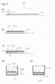
- FIGS. 2A to 2E illustrate the method according to the invention for producing a microtiter plate with capture molecule coatings. The process consists of several steps.
- a first support membrane M1 is provided.
- a second support membrane M2 is also provided.
- the first carrier membrane M2 is coated with respective first blot lines BL11, . . . , BL14, which can also be referred to as a first set of blot lines BL1.
- the respective first blot lines BL11, . . . , BL14 each have a respective capture molecule type. These respective capture molecule types can be different.
- the carrier membrane M1 is coated with the blot lines BL1 by moving a plurality of dispensing capillaries or dispensing needles D along an application direction or coating direction AR.
- the dispensing needles D are guided over the membrane M1 in the application direction AR.
- the movement is in particular a linear movement.
- first membrane segment MS1 which in the Figure 2A indicated by a broken line, from the first support membrane M1.
- the membrane segment MS1 then has respective line sections LA11, . . . LA14 of the respective first blot lines BL11, .., BL14, as in FIG Figure 2C shown.
- a line section can also be referred to as a line segment or a blot line segment.
- a second membrane segment MS2 is separated from the second carrier membrane M2. How from the Figure 2C As can be seen, the second membrane segment MS2 has respective line sections LA21, ..., LA23 of the respective second blot lines BL21, ..., BL23.
- membrane segments MS11 or MS21 can preferably be separated from the membranes M1 or M2.
- the first membrane segment MS1 is also positioned and fixed on a carrier layer T and the second membrane segment MS2 is positioned and fixed on the carrier layer T.
- the membrane segment MS11 is also positioned and fixed on the carrier layer T and the membrane segment MS21 on the carrier layer T.
- the membrane segment MS11 is also positioned and fixed on the carrier layer T and the membrane segment MS21 is positioned and fixed on the carrier layer T in on the carrier layer, in particular on a further area TS2, which preferably forms a further carrier layer segment.
- the dashed circular line TS in the Figure 2C indicates a carrier layer segment which is separated from the carrier layer and which has the first and the second membrane segment MS1, MS2.
- the carrier layer segment TS is also positioned and fixed in a well W of a microtiter plate.
- Figure 2D shows the well wall WW and the carrier layer segment TS from above, so that the carrier layer TS is visible from the opening of the well W.
- the Figure 2E 12 illustrates the position of the carrier layer segment TS with the membrane segments MS1, MS2 located thereon above the well bottom WB and between the well walls WW in the lateral sectional view of the well W
- the positioning and fixing of the carrier layer segment TS in the well W takes place in particular in such a way that the membrane segments MS1, MS2 are visible from the opening OF of the well.
- the fixing of the membrane segments or the fixing of the carrier layer segment can preferably be referred to as mechanical fixing.
- the membrane segments can preferably also be referred to as carrier membrane segments.
- the first blot lines BL1 on the carrier membrane M1 are blocked with a first blocking buffer. It is also preferred after the coating of the second support membrane M2 with the second blot lines BL2 a blocking of the second blot lines BL2 on the second support membrane M2 with a second blocking buffer, which in particular can be a different blocking buffer than the first blocking buffer.
- the first line segments LA11, . . . , LA13 are therefore preferably blocked with the first blocking buffer and the second line segments are blocked with the second blocking buffer.
- the method according to the invention has the advantage that a plurality of capture molecule coatings can be introduced or positioned above the well bottom of the well of a microtiter plate without a dispensing capillary having to be positioned and moved directly within the narrow space of a well.
- the carrier layer segment TS has to be positioned in the well above the well bottom in a single step, there is only one single work step in which a particularly precise positioning of a tool within the interior of the depression of the well must be achieved.
- the dispensing capillaries can be positioned outside of the well, so that more work space is available during this step.
- standard line coating devices which have the dispensing capillary can be used without having to provide special dispensing devices for applying catcher molecule coatings to a well bottom.
- different combinations of capture molecule coatings or blot line segments can be configured or produced relatively easily for different diagnostic questions and for different wells.
- the second carrier membrane which has the second blot lines
- other combinations of capture molecule types can be achieved on the support layer segment by a third carrier membrane with third blot lines located thereon which have capture molecule types other than those of the second blot lines.
- a batch control of the capture molecules after applying the blot lines to a membrane is possible in a simple manner, since, for example, a test membrane segment MS11 can be separated from the membrane M1, which can be processed or incubated in a separate processing well or blot tray to check the quality of the To check capture molecules of the BL1 blot lines.
- a batch control therefore, no processing or incubation of the catcher molecule coatings has to take place directly in a well, in which case an entire microtiter plate would then later have to be disposed of.
- the membrane segment MS11 can be processed and evaluated separately outside of the microtiter plate.
- a microtiter plate is a unit that has a number of wells or recesses that are mechanically firmly connected to one another.
- the individual wells can preferably be arranged in a matrix arrangement, as in the microtiter plate MT from FIG figure 1 .
- a plurality of wells can be arranged along only one propagation direction or a linear arrangement, as in FIG Figure 6A shown as a microtiter plate MTX.
- the particularly preferred method proposed here can also block the first blot lines BL1 on the membrane M1 with a different blocking buffer than for the second Blot lines BL2 on membrane M2. This means that individual blocking liquids can be used depending on the type of capture molecule, which enables greater stability of the respective blot lines.
- the first blot lines are preferably blot lines running parallel to one another.
- the second blot lines are preferably blot lines running parallel to one another.
- the membrane segments are separated by cutting them out, preferably by punching them out.
- the punching out is particularly preferably carried out by means of a punching knife.
- the membrane segments each have a respective longitudinal extension, a respective longitudinal axis along the longitudinal extension and also a respective transverse axis perpendicular to the respective longitudinal axis.
- the central axis is in particular a common central axis.
- the membrane segments are fixed to the carrier layer by means of an adhesive layer located between the membrane segments and the carrier layer or applied there.
- the carrier layer segment is fixed in the well on the bottom of the well by means of an adhesive layer located between the well bottom and the carrier layer segment or applied to the carrier layer segment.
- the carrier layer segment is fixed in the well by clamping the carrier layer segment within the inner side wall of the well.
- a microtiter plate with at least one well with catcher molecule coatings, having a carrier layer segment which is positioned and fixed above a well bottom in the well, and also two or more carrier membrane segments positioned and fixed on the carrier layer segment, each of which has a plurality of blot line segments, with the respective blot line segments having respective Have capture molecule types.
- the blot line segments of a carrier membrane segment are blot line segments running parallel to one another.
- the microtiter plate comprises at least one adhesive layer above the carrier layer segment, on which the carrier membrane segments are fixed.
- the adhesive layer consists of a plurality of adhesive layer sections, with the adhesive layer sections in particular also being sections of a double-sided adhesive film.
- the carrier layer segment is fixed to the bottom of the well by means of a further adhesive layer, the further adhesive layer preferably being a double-sided adhesive film.
- the carrier membrane segments each have a respective elongate extent, also each have a respective longitudinal axis along the elongate extent and also each have a respective transverse axis perpendicular to the respective longitudinal axis
- the carrier layer segment also having a circular base area and the elongate carrier membrane segments also being in the manner on the carrier layer segment are positioned such that the carrier membrane segments are each positioned with their respective longitudinal axes perpendicular to a central axis MA of the circular base area of the carrier layer segment, further the first carrier membrane segment is positioned with its transverse axis offset from the central axis by a first distance and furthermore the second carrier membrane segment is positioned with its transverse axis positioned offset from the central axis by a second distance different from the first distance.
- a method comprising the steps: providing a microtiter plate according to the invention having the carrier membrane segments, incubating the carrier membrane segments with a patient sample, a conjugate and a substrate.
- the method preferably comprises the further steps: capturing an image which represents the carrier layer segment and the carrier membrane segments, identifying the first carrier membrane segment and the second carrier membrane segment in the image, determining respective binding measures which indicate a respective binding of antibodies or antigens to respective blot line segments, as well as Output of the respective bond dimensions.
- a digital image processing method is also proposed, the steps: providing a microtiter plate proposed herein, capturing an image representing the carrier layer segment and the carrier membrane segments, providing a data set which indicates respective membrane segment types for respective spatial positions of respective transverse axes, identifying the first carrier membrane segment and the second Support membrane segment in the image using the data set, providing sub-images representing the respective membrane segments.
- the method preferably also comprises: determining respective binding measures which indicate a respective binding of antibodies or antigens to respective blot line segments on the basis of the partial images, and outputting the respective binding measures.
- the blot lines BL1 run parallel to one another. Furthermore, the blot lines BL2 in particular run parallel to one another.
- Figure 3A shows a side view of the first carrier membrane M1, on which the blot lines are applied along the application direction AR. These blot lines are not shown separately in this side view, but can be assumed to be on the surface of the membrane M1.
- the membrane segments can preferably be fixed on the carrier layer. It is also explained how the carrier layer segment is fixed in the well above the bottom of the well.
- the Figure 3A shows the carrier membrane M1 in a side view, which is applied to a double-sided adhesive film K1.
- a protective film F1 is preferably located below the double-sided adhesive film K1.
- a membrane segment MS1 is separated by cutting it out, preferably by punching it out. Punching is particularly preferably carried out using a punching knife.
- the double-sided adhesive film K1 represents an adhesive layer.
- the double-sided adhesive film K1 has an adhesion promoter, in particular on its top and bottom, which can be selected depending on the membrane material M1 to be applied.
- adhesion promoters are, for example, from EP 2327636 B1 known.
- the adhesive layer K1 can preferably be a UV adhesive previously applied to the carrier layer T as an alternative to the embodiment of a double-sided adhesive film.
- the UV adhesive can then be referred to as an adhesive layer.
- the membrane segment MS1 is preferably cut out by means of the punching tool SW1.
- the membrane segment MS1 is preferably detached in such a way that an adhesive layer segment K11 is also detached.
- the membrane segment MS1 can then, as in the Figure 2D shown, are fixed to a carrier layer T by means of the adhesive layer segment K11.
- membrane segment MS1 and adhesive layer segment K11 can be expelled from the punching tool SW1 and thus applied to the carrier layer T by introducing compressed air into the punching tool SW1.
- the fixing of the membrane segment MS1 on the carrier layer T thus takes place by means of an adhesive layer or an adhesive layer segment K11 located between the membrane segments and the carrier layer.
- Analogous steps can be carried out for a second carrier membrane M2, so that a second membrane segment MS2 is fixed to the carrier layer TS by means of an adhesive layer K21.
- the carrier layer T is preferably located on a further adhesive layer K2.
- the further adhesive layer K2 is preferably located on a further protective film F2.
- the carrier layer segment TS is then detached, in particular by means of cutting out, preferably by means of punching out, particularly preferably by means of a punching knife SW2 in the form of a punching tool.
- the separation preferably takes place in such a way that an adhesive layer segment K22 or an adhesive layer K22 is also separated and that the carrier layer segment TS is then fixed, as in Figure 3D shown, takes place by means of the adhesive layer K22 located between the corrugated base WB and the carrier layer segment TS.
- the combination of adhesive layer K22, carrier layer segment TS, adhesive layer segments K11, K21 and membrane segments MS1, MS2 can be expelled from the punching tool SW2 by applying pressure to the punching tool and positioned and fixed on the well bottom.
- FIG. 3C A further alternative embodiment of the method according to the invention will now be described with reference to FIG Figure 3C set forth.
- a carrier layer segment TS can be separated from the carrier layer T by means of a punching tool SW2. It can then, as in the Figure 3E As can be seen, the carrier layer segment TS is fixed in the well W2, which preferably has conically tapering well walls WW2, by clamping the carrier layer segment TS within the inner side walls ISW of the well W2.
- the advantage of such a clamping method according to the Figure 3E is that no additional layer of adhesive is necessary.
- the advantage of providing a further adhesive layer K22 is that lower demands are placed on the tolerance dimensions of the base area of the carrier layer segment TS compared to the dimensions of the inner space of the well W. If an adhesive layer K22 is used, any gaps that may occur between the carrier layer segment TS and the well walls WW when positioning and fixing the membrane segments are tolerable. This is not the case if the carrier layer segment TS is clamped in the well W2, as in FIG Figure 3E shown.
- Figures 4A-C show a further preferred embodiment of the method according to the invention, in which, instead of a double-sided adhesive film, an adhesive K1X applied over a large area is alternatively used as the adhesive layer.
- the membrane M1 is provided with blot lines applied in the application directions AR.
- a protective film F1 is preferably present.
- a membrane segment MS1 is then separated out, particularly preferably by means of a punching tool SW1.
- the Figure 4B shows a structure that then results, in which membrane segments MS1, MS2 are positioned and fixed on an adhesive layer K1X applied over the entire surface of the carrier layer T.
- the Figure 4C shows the separation of the carrier layer segment TS2 from the carrier layer T.
- the carrier layer segment TS2 with the membrane segments MS1, MS2 located and positioned and fixed thereon can then preferably be positioned and fixed in the well W by means of an adhesive layer K22X previously applied to the well bottom.
- the carrier layer segment TS2 by clamping the carrier layer segment TS2 within the inner side walls of the well W2.
- the embodiments from the Figure 3D as well as the Figure 4D have in common that the carrier layer segment TS, TS2 is positioned and fixed above the well bottom WB in the well W2, with two or more membrane segments MS1, MS2 positioned and fixed on the carrier layer segment TS, TS2, each of which has several blot line segments, wherein the respective blot line segments have respective capture molecule types. Furthermore, in these two embodiments from the Figure 3D and 4D there is at least one adhesive layer K11, K21, K11X above the carrier layer segment, on which the carrier membrane segments MS1, MS2 are fixed.
- the carrier layer segment TS, TS2 is fixed to the well base WB of the well W by means of a further adhesive layer K22, K22X.
- K22, K22X a further adhesive layer
- the membrane segments MS1, MS2 can be positioned in relation to the carrier layer segment TS, TS2 outside the depression of the well, with a larger agitation space corresponding to the tools then being provided for this step than inside the well.
- the adhesive layer for fixing the carrier membrane segments MS1, MS2 from the embodiment of FIG Figure 3D is given by several adhesive layer sections K11, K21.
- the Figure 5A shows a schematic representation of a preferred embodiment of a carrier layer segment TS with at least two membrane segments MS1, MS2. A further, third membrane segment MS3 is preferably present.
- the membrane segments MS1, MS2 each have an elongate extent.
- the membrane segments MS1, MS2 each have a longitudinal axis LAC1, LAC2 along their longitudinal extension. Furthermore, the membrane segments MS1, MS2 each have a transverse axis Q1, Q2 perpendicular to the longitudinal axis LAC1, LAC2.
- the carrier layer segment TS has a circular base area FL.
- the membrane segments MS1, MS2 are positioned on the carrier layer segment TS in such a way that the elongated membrane segments MS1, MS2 are positioned on the carrier layer segment TS in a special way.
- the carrier membrane segments MS1, MS2 are positioned with their respective longitudinal axes LAC1, LAC2 perpendicular to a specific central axis MA of the circular base area FL of the carrier layer segment TS.
- the first carrier membrane segment MS1 is positioned with its transverse axis Q1 offset by a first distance DI1 relative to the central axis MA.
- this distance DI1 is zero (0).
- the second support membrane segment MS2 is positioned offset by a second distance DI2 with its transverse axis Q2 relative to the central axis MA. This second distance DI2 differs from the first distance DI1.
- This embodiment of a carrier segment TS with membrane segments MS1, MS2 within a microtiter plate is therefore particularly advantageous since due to the spatial arrangement of the membrane segments MS1, MS2 an assignment of corresponding image areas MSX11, MSX12, see Figure 6C , The corresponding membrane segments MS1, MS2 can be made to certain membrane segment types.
- the first membrane segment MS1 from Figure 5A be a membrane segment MSX1 on which a first line segment LAX1 of a blot line is present.
- a second line segment LAX2 can also be present, for example.
- the line segment LAX1 can be a serum control.
- the lineage segment LAX2 can be a conjugate control.
- the second membrane segment MS2 can be a membrane segment MSX2 which has four different bands or line segments of blot lines.
- This can be line segments LAX3 to LAX6.
- the line segment LAX3 can have a first type of scavenger molecule and the line segment LAX4 can have a second type of scavenger molecule.
- a microtiter plate proposed here having corresponding carrier membrane segments, can therefore be incubated with a patient sample, a conjugate and a substrate. An image can then also be captured which represents the carrier layer segment and the carrier membrane segments.
- the Figure 6A shows an embodiment of a microtiter plate MTX with corresponding membrane segments and discolorations appearing on the bands or line segments located thereon.
- the Figure 6B shows an exemplary image B, which represents a carrier layer segment with carrier membrane segments located thereon.
- the Figure 6C shows respective image sections of image B from FIG Figure 6B , representing respective membrane segments MSX11, MSX12, MSX13.
- the Figure 7A shows the basic steps of a digital image processing method.
- a step S1 the image that represents the carrier layer segment and the carrier membrane segments is captured.
- the first carrier membrane segment and the second carrier membrane segment are identified in the image, in particular by means of a data set DA provided.
- This data set indicates at least two types of support membrane segments and respective locations of the types of support membrane segments relative to a central axis of a circular area of a support layer segment.
- the data set DA indicates distances of transverse axes of the membrane segments from a central axis of the circular area of the backing layer segment.
- respective binding measures are determined, which indicate a respective binding of antibodies or antigens to respective blot line segments.
- binding measures can be derived from gray values of corresponding bands or line segments or line sections of the membrane segments.
- step S4 the respective bond dimensions are output.
- the Figure 7B shows a first particular embodiment of in relation to Figure 7A explained procedure.
- an image is recorded in a step S10.
- a circular area of the carrier layer segment is created in the image, as in FIG Figure 5A shown, detected by a segmentation step.
- the respective membrane segment areas are recognized by means of segmentation.
- the transverse axes of the membrane segment surfaces are determined.
- the central axis of the circular carrier layer segment is determined, with this central axis running parallel to the transverse axes of the membrane segment surfaces.
- a data set DA is also provided, which can preferably be referred to as higher knowledge.
- This data record DA indicates a respective membrane segment type for respective distances of respective transverse axes relative to the central axis.
- the data set indicates a corresponding spatial sequence of line segments or corresponding bands with capture molecule types on the corresponding membrane segment for each membrane segment type. From this, the sequence of the bands or line segments with the corresponding capture molecule can then be determined in a corresponding partial image of a membrane segment, as in Figure 6C shown, can be derived.
- a step S16 the band intensity or the line segments are analyzed by means of digital image processing of an output of corresponding binding measures which indicate the respective binding of antibodies or antigens to the respective blot line segments.
- Such a degree of binding can be, for example, a medium gray area with a band or a line segment.
- a measure of commitment can be a qualitative measure of commitment, which indicates a positive or negative decision.
- the Figure 7C shows an alternative image processing method to that of FIG Figure 7B .
- the image is recorded in step S20. Furthermore, by means of segmentation, the diaphragm segment surfaces are recognized in a step S21. Furthermore, in a step S22, the transverse axes of the membrane segment surfaces are determined. In the event that the carrier segment TS, see the embodiment from the Figure 5A , has three membrane segments MS1, MS2, MS3, the respective positions of the respective transverse axes can then be determined. Furthermore, the relative distances in the longitudinal direction or orthogonally to the transverse axis to the respective other transverse axes can be determined for each transverse axis. A minimum distance is then determined for a specific transverse axis in relation to another, nearest transverse axis.
- the transverse axis Q1 has a minimum distance DI1 of 0 (zero) from the transverse axis Q3.
- the transverse axis Q2 has a minimum distance DI2 compared to the transverse axis Q1 and the transverse axis Q3.
- the respective membrane segment types or membrane segments MS1, MS2, MS3 or MSX1, MSX2, MSX3 can then be identified in order to also reliably identify their spatial orientation and thus the sequence of the corresponding line segments LAX1, LAX2, LAX3, LAX6, LAX7, LAX10 .
- a step S24 the band intensities are then analyzed via image processing and the respective binding measures for the respective bands are output.
- the data set indicates respective membrane segment types for respective spatial positions of respective transverse axes.
- the data record can also be given in the form of several partial data records.
- an image B is captured, which represents the carrier layer segment TS and the carrier membrane segments MS1, MS2.
- a data set is provided which indicates respective membrane segment types for respective spatial positions of respective transverse axes.
- the first carrier membrane segment MS1 and the second carrier membrane segment MS2 are identified in the image B using the data set.
- partial images MSX11, MSX12 are provided, which represent the respective membrane segments MS1, MS2, and the respective membrane segment types are indexed for the respective partial images MSX11, MSX12. This indexing of the membrane segment types can be done by providing the partial images MSX11, MSX12 in a specific order. Alternatively, this indexing can take place in that a respective partial image MSX11, MSX12 is provided together with a respective partial data record which indicates the respective membrane segment type for a respective partial image.
- the respective binding measures are preferably determined, which indicate a respective binding of antibodies or antigens to the respective blot line segments, and the respective binding measures are output.
- the membrane segments can preferably be referred to as blot strips or line blot strips Reference 1 ( Raoult, D, and Dasch, GA, 1989, The line blot: an immunoassay for monoclonal and other antibodies. Its application to the serotyping of gram-negative bacteria. J. Immunol. Methods, 125(1-2), 57-65 ; WO2013041540 ).
- the term "blot strip” or "line blot” or “membrane segment” within the meaning of this application is regarded as a test strip, particularly preferably as a membrane-based strip, which is coated with at least two different substances for capturing antibodies or antigens, the Substances are preferably polypeptides. These two substances are preferably applied as respective line segments spatially separated from one another on the membrane segment or the line blot or the test strip.
- Such a membrane segment or such a test strip or line blot preferably has one or more areas which are called a control band, such a control band being suitable for confirming that the membrane segment or line blot or test strip is long enough and under appropriate conditions with a patient sample was contacted.
- the patient sample is preferably human blood, preferably human blood plasma or human blood serum, more preferably diluted human blood plasma or diluted human blood serum.
- Different line blots of two blot strips are described in the prior art, for example in reference 2 ( van Oss, JC, and Regenmortel, MHV, Immunochemistry, 1994, Marcell Dekker, especially Chapter 35 ).
- a support membrane is preferably a nitrocellulose membrane, a nylon membrane or a PVDF membrane.
- the carrier membrane is thus suitable for adsorbing a solution of capture molecule and buffer.
- the membrane is coated with a capture molecule by applying such a solution to the membrane.
- a carrier layer is preferably a mechanically strong plastic layer or a mechanically flexible plastic film.
- the plastic can in particular be PET (polyethylene terephthalate), in particular antistatic PET.
- a blocking buffer is a buffer that prevents non-specific binding of the detection antibody or the detection antigen to the surface of the membrane prevented.
- a buffer contains either proteins or other components to block binding sites so that non-specific binding is prevented.
- a double-sided adhesive film can be a film which is coated on both sides with an adhesion promoter as described above.
- aspects have been described in the context of a device, it is understood that these aspects also represent a description of the corresponding method, so that a block or a component of a device is also to be understood as a corresponding method step or as a feature of a method step. Analogously, aspects that have been described in connection with or as a method step also represent a description of a corresponding feature of a corresponding device.
- the line blot strips were processed manually in a blot tray according to the instructions DN_2131G_A_DE_C11 of the product Anti-Borrelia-EUROLINE-RN-AT (IgG).
- the antigens and antibodies in the microtiter plate were processed according to the same instructions, with the volumes of the reagents being adjusted. This adjustment took into account the difference in volume between the blot tray and the well of the microtiter plate.
- the image acquisition and evaluation of the lineblot strips was carried out in a first attempt with the products EUROBIotScanner and EUROLineScan.
- the images of the wells were recorded in a second approach with a newly developed image recording system, the evaluation of the well images was also carried out with the product EUROLineScan.
- the figure 8 shows a table with results.
- the intensity values of the two approaches are comparable or correlate strongly with each other, as later also with reference to figure 9 still stated.
- the respective positive/negative evaluations for the respective line blot strip (EL) or microtiter plate (MTP) approaches using respective, individual threshold values for the respective approaches can be found in the last two columns. Here a match of all respective positive/negative evaluations can be determined.
- the serum control and the conjugate control each used antibodies as capture molecules. These antibodies of the respective controls are each anti-human antibodies.
- the antigen with the designation p39 is also known under the designation BmpA, a corresponding Uniprot number is P0C223.
- the antigen, designated DbpA has a corresponding Uniprot number O50917.
- the antigen with the designation p41 is also known as flagellin, a corresponding Uniprot number is C3VMP5.
- the antigen designated p100 has a corresponding Uniprot number Q45013.
- the antigen with the designation VlsE Ba is also known under the designation VlsE Borrelia afzelii, a corresponding Uniprot number is Q5DVM0.
- the antigen with the designation VlsE Bb is also known under the designation VlsE Borrelia burgdorferi, a corresponding Uniprot number is O06878.
- the antigen with the designation VlsE Bg is also known under the designation VlsE Borrelia garinii, a corresponding Uniprot number is Q5DVM1.
- the antigen with the designation OspC Mix is also known under the designation OspC, a corresponding Uniprot number is Q07337.
- figure 9 shows a correlation of the intensity values for common line blot strips (EUROLINE) on the x-axis and wells of microtiter plates (EUROMicroblot) on the y-axis across all Antigens as well as antibodies and all patient samples.
Priority Applications (2)
| Application Number | Priority Date | Filing Date | Title |
|---|---|---|---|
| EP22160018.2A EP4239336B1 (fr) | 2022-03-03 | 2022-03-03 | Procédé de fabrication d'une plaque de microtitrage dotée de revêtements à molécules de capture et plaque de microtitrage |
| PT221600182T PT4239336T (pt) | 2022-03-03 | 2022-03-03 | Método para a produção de uma placa de microtitulação com revestimentos de moléculas de captura e placa de microtitulação |
Applications Claiming Priority (1)
| Application Number | Priority Date | Filing Date | Title |
|---|---|---|---|
| EP22160018.2A EP4239336B1 (fr) | 2022-03-03 | 2022-03-03 | Procédé de fabrication d'une plaque de microtitrage dotée de revêtements à molécules de capture et plaque de microtitrage |
Publications (2)
| Publication Number | Publication Date |
|---|---|
| EP4239336A1 true EP4239336A1 (fr) | 2023-09-06 |
| EP4239336B1 EP4239336B1 (fr) | 2024-01-10 |
Family
ID=80628835
Family Applications (1)
| Application Number | Title | Priority Date | Filing Date |
|---|---|---|---|
| EP22160018.2A Active EP4239336B1 (fr) | 2022-03-03 | 2022-03-03 | Procédé de fabrication d'une plaque de microtitrage dotée de revêtements à molécules de capture et plaque de microtitrage |
Country Status (2)
| Country | Link |
|---|---|
| EP (1) | EP4239336B1 (fr) |
| PT (1) | PT4239336T (fr) |
Citations (6)
| Publication number | Priority date | Publication date | Assignee | Title |
|---|---|---|---|---|
| EP2327636B1 (fr) | 2008-06-27 | 2012-08-22 | Constantia Teich GmbH | Flacon pour médicaments fermé par un couvercle |
| WO2013041540A1 (fr) | 2011-09-24 | 2013-03-28 | Euroimmun Medizinische Labordiagnostika Ag | Bandelette d'étalonnage pour un immunotransfert |
| DE102013008468A1 (de) * | 2013-05-21 | 2014-11-27 | Euroimmun Medizinische Labordiagnostika Ag | Verfahren zur automatisierten Auswertung von inkubierten lmmunoblotstreifen |
| US20150011437A1 (en) * | 2012-07-09 | 2015-01-08 | Jiandi Zhang | Multi-unit plate for immunoblot analysis |
| US9366668B2 (en) * | 2007-02-15 | 2016-06-14 | Lawrence Livermore National Security, Llc | Device, array, and methods for disease detection and analysis |
| EP2427267B1 (fr) | 2009-05-04 | 2021-02-24 | BioCopy Holding AG | Support reconnaissable pour procédés de mesure optiques |
-
2022
- 2022-03-03 EP EP22160018.2A patent/EP4239336B1/fr active Active
- 2022-03-03 PT PT221600182T patent/PT4239336T/pt unknown
Patent Citations (6)
| Publication number | Priority date | Publication date | Assignee | Title |
|---|---|---|---|---|
| US9366668B2 (en) * | 2007-02-15 | 2016-06-14 | Lawrence Livermore National Security, Llc | Device, array, and methods for disease detection and analysis |
| EP2327636B1 (fr) | 2008-06-27 | 2012-08-22 | Constantia Teich GmbH | Flacon pour médicaments fermé par un couvercle |
| EP2427267B1 (fr) | 2009-05-04 | 2021-02-24 | BioCopy Holding AG | Support reconnaissable pour procédés de mesure optiques |
| WO2013041540A1 (fr) | 2011-09-24 | 2013-03-28 | Euroimmun Medizinische Labordiagnostika Ag | Bandelette d'étalonnage pour un immunotransfert |
| US20150011437A1 (en) * | 2012-07-09 | 2015-01-08 | Jiandi Zhang | Multi-unit plate for immunoblot analysis |
| DE102013008468A1 (de) * | 2013-05-21 | 2014-11-27 | Euroimmun Medizinische Labordiagnostika Ag | Verfahren zur automatisierten Auswertung von inkubierten lmmunoblotstreifen |
Non-Patent Citations (5)
| Title |
|---|
| A. ALRASHOUDI ABDULELAH ET AL: "Fabrication of a Lateral Flow Assay for Rapid In-Field Detection of COVID-19 Antibodies Using Additive Manufacturing Printing Technolog", INTERNATIONAL JOURNAL OF BIOPRINTING, vol. 7, no. 4, 23 August 2021 (2021-08-23), pages 399, XP055932370, ISSN: 2424-7723, Retrieved from the Internet <URL:https://ijb.whioce.com/index.php/int-j-bioprinting/article/viewFile/399/265> DOI: 10.18063/ijb.v7i4.399 * |
| ANFOSSI LAURA ET AL: "Multiplex Lateral Flow Immunoassay: An Overview of Strategies towards High-throughput Point-of-Need Testing", BIOSENSORS, vol. 9, no. 1, 26 December 2018 (2018-12-26), CH, pages 1 - 14, XP055855313, ISSN: 2079-6374, DOI: 10.3390/bios9010002 * |
| JUNE MAI ET AL, 1 July 2015 (2015-07-01), XP055743991, Retrieved from the Internet <URL:https://cdn.shopify.com/s/files/1/0718/6639/files/NatureApplicationNote_MemAssay.pdf?4> [retrieved on 20201026] * |
| RAOULT, DDASCH, G. A.: "The line blot: an immunoassay for monoclonal and other antibodies. Its application to the serotyping of gram-negative bacteria", J. IMMUNOL. METHODS, vol. 125, 1989, pages 57 - 65, XP023653127, DOI: 10.1016/0022-1759(89)90078-1 |
| SUJATHA RAMACHANDRAN ET AL: "A Rapid, Multiplexed, High-Throughput Flow-Through Membrane Immunoassay: A Convenient Alternative to ELISA", DIAGNOSTICS, vol. 3, no. 2, 2 April 2013 (2013-04-02), pages 244 - 260, XP055549823, DOI: 10.3390/diagnostics3020244 * |
Also Published As
| Publication number | Publication date |
|---|---|
| PT4239336T (pt) | 2024-03-14 |
| EP4239336B1 (fr) | 2024-01-10 |
Similar Documents
| Publication | Publication Date | Title |
|---|---|---|
| EP2758783B1 (fr) | Un procédé d'immunotransfert | |
| EP1136822B1 (fr) | Méthode pour l'identification des structures cibles spécifiques aux cellules | |
| EP0810428B1 (fr) | Appareil automatique et procédé de mesure et d'identification de molécules ou de fragments de molécules | |
| DE3322373C2 (de) | Testmittel und Verfahren zum Nachweis von Antigenen und/oder Antikörpern | |
| EP2223111B1 (fr) | Procédé elispot faisant appel à deux systèmes de filtration | |
| WO2005083434A2 (fr) | Dispositif et procede d'analyse optique de bandelettes de test | |
| DE69531575T2 (de) | Lesekopf mit veränderbarer Auflösung | |
| DE60215302T2 (de) | Einrichtungen und verfahren für bildobjekte | |
| EP4239336B1 (fr) | Procédé de fabrication d'une plaque de microtitrage dotée de revêtements à molécules de capture et plaque de microtitrage | |
| DE102010020785A1 (de) | Vorrichtung und Verfahren zum Erkennen von magnetisch markierten Mikroobjekten | |
| EP3591403B1 (fr) | Procédé de détection automatisée d'anticorps dans un échantillon biologique liquide à l'aide d'une puce à antigène et puce à antigène correspondante | |
| DE102011117320A1 (de) | Vorrichtung und Verfahren zum Nachweis von in biologischen oder chemischen Proben vorliegenden Substanzen | |
| EP3149477A1 (fr) | Dispositif et procédé de détermination d'antigènes de groupes sanguins au moyen d'un anticorps incomplet | |
| EP2288916A1 (fr) | Procédé d'immunochromatographie et système de test pour la détermination d'au moins un analyte dans une solution test à analyser | |
| EP1713589B1 (fr) | Element d'analyse et procede pour analyser le sang | |
| EP2059906A2 (fr) | Procédé de détermination quantitative de la co-localisation de marqueurs moléculaires dans les coupes de tissu | |
| DE102011117311A1 (de) | Vorrichtung und Verfahren zum Nachweis von in biologischen oder chemischen Proben vorliegenden Substanzen | |
| DE60317497T2 (de) | Verfahren, system und kit zum nachweis eines analyten in einer probe | |
| EP2771697B1 (fr) | Dispositif et procédé de détection de substances présentes dans des prélèvements biologiques ou chimiques | |
| EP2771672B1 (fr) | Dispositif et procédé de détection de substances présentes dans des prélèvements biologiques ou chimiques | |
| DE202007014762U1 (de) | Anordnung zur Aufbereitung von zu untersuchendem Gewebe sowie Objektträger für zu untersuchendes Gewebe | |
| DE19628821A1 (de) | Verfahren zur Untersuchung der Nierenfunktion | |
| DE102005001362A1 (de) | Verfahren und Vorrichtung zur Quantifizierung von Proteinen | |
| DE19645569C1 (de) | Vorrichtung zum quantifizierenden und differenzierenden Nachweis verschiedener Biomoleküle in einem einzigen Testansatz | |
| EP0374686A2 (fr) | Méthode pour améliorer la correction et la reproduction de donnéös de mesure d essais immunométriques |
Legal Events
| Date | Code | Title | Description |
|---|---|---|---|
| PUAI | Public reference made under article 153(3) epc to a published international application that has entered the european phase |
Free format text: ORIGINAL CODE: 0009012 |
|
| STAA | Information on the status of an ep patent application or granted ep patent |
Free format text: STATUS: REQUEST FOR EXAMINATION WAS MADE |
|
| 17P | Request for examination filed |
Effective date: 20230228 |
|
| AK | Designated contracting states |
Kind code of ref document: A1 Designated state(s): AL AT BE BG CH CY CZ DE DK EE ES FI FR GB GR HR HU IE IS IT LI LT LU LV MC MK MT NL NO PL PT RO RS SE SI SK SM TR |
|
| GRAP | Despatch of communication of intention to grant a patent |
Free format text: ORIGINAL CODE: EPIDOSNIGR1 |
|
| STAA | Information on the status of an ep patent application or granted ep patent |
Free format text: STATUS: GRANT OF PATENT IS INTENDED |
|
| INTG | Intention to grant announced |
Effective date: 20230920 |
|
| GRAS | Grant fee paid |
Free format text: ORIGINAL CODE: EPIDOSNIGR3 |
|
| GRAA | (expected) grant |
Free format text: ORIGINAL CODE: 0009210 |
|
| STAA | Information on the status of an ep patent application or granted ep patent |
Free format text: STATUS: THE PATENT HAS BEEN GRANTED |
|
| AK | Designated contracting states |
Kind code of ref document: B1 Designated state(s): AL AT BE BG CH CY CZ DE DK EE ES FI FR GB GR HR HU IE IS IT LI LT LU LV MC MK MT NL NO PL PT RO RS SE SI SK SM TR |
|
| REG | Reference to a national code |
Ref country code: GB Ref legal event code: FG4D Free format text: NOT ENGLISH |
|
| REG | Reference to a national code |
Ref country code: CH Ref legal event code: EP |
|
| REG | Reference to a national code |
Ref country code: DE Ref legal event code: R096 Ref document number: 502022000384 Country of ref document: DE |
|
| REG | Reference to a national code |
Ref country code: IE Ref legal event code: FG4D Free format text: LANGUAGE OF EP DOCUMENT: GERMAN |
|
| REG | Reference to a national code |
Ref country code: PT Ref legal event code: SC4A Ref document number: 4239336 Country of ref document: PT Date of ref document: 20240314 Kind code of ref document: T Free format text: AVAILABILITY OF NATIONAL TRANSLATION Effective date: 20240311 |
|
| P01 | Opt-out of the competence of the unified patent court (upc) registered |
Effective date: 20240229 |