EP4238737B1 - Schiebeanordnung für spritzgussformen - Google Patents
Schiebeanordnung für spritzgussformen Download PDFInfo
- Publication number
- EP4238737B1 EP4238737B1 EP23382112.3A EP23382112A EP4238737B1 EP 4238737 B1 EP4238737 B1 EP 4238737B1 EP 23382112 A EP23382112 A EP 23382112A EP 4238737 B1 EP4238737 B1 EP 4238737B1
- Authority
- EP
- European Patent Office
- Prior art keywords
- slide
- injection molds
- slide assembly
- slide body
- insert
- Prior art date
- Legal status (The legal status is an assumption and is not a legal conclusion. Google has not performed a legal analysis and makes no representation as to the accuracy of the status listed.)
- Active
Links
Images


Classifications
-
- B—PERFORMING OPERATIONS; TRANSPORTING
- B29—WORKING OF PLASTICS; WORKING OF SUBSTANCES IN A PLASTIC STATE IN GENERAL
- B29C—SHAPING OR JOINING OF PLASTICS; SHAPING OF MATERIAL IN A PLASTIC STATE, NOT OTHERWISE PROVIDED FOR; AFTER-TREATMENT OF THE SHAPED PRODUCTS, e.g. REPAIRING
- B29C45/00—Injection moulding, i.e. forcing the required volume of moulding material through a nozzle into a closed mould; Apparatus therefor
- B29C45/17—Component parts, details or accessories; Auxiliary operations
- B29C45/26—Moulds
- B29C45/33—Moulds having transversely, e.g. radially, movable mould parts
-
- B—PERFORMING OPERATIONS; TRANSPORTING
- B29—WORKING OF PLASTICS; WORKING OF SUBSTANCES IN A PLASTIC STATE IN GENERAL
- B29C—SHAPING OR JOINING OF PLASTICS; SHAPING OF MATERIAL IN A PLASTIC STATE, NOT OTHERWISE PROVIDED FOR; AFTER-TREATMENT OF THE SHAPED PRODUCTS, e.g. REPAIRING
- B29C33/00—Moulds or cores; Details thereof or accessories therefor
- B29C33/30—Mounting, exchanging or centering
- B29C33/32—Mounting, exchanging or centering using magnetic means
-
- B—PERFORMING OPERATIONS; TRANSPORTING
- B29—WORKING OF PLASTICS; WORKING OF SUBSTANCES IN A PLASTIC STATE IN GENERAL
- B29C—SHAPING OR JOINING OF PLASTICS; SHAPING OF MATERIAL IN A PLASTIC STATE, NOT OTHERWISE PROVIDED FOR; AFTER-TREATMENT OF THE SHAPED PRODUCTS, e.g. REPAIRING
- B29C45/00—Injection moulding, i.e. forcing the required volume of moulding material through a nozzle into a closed mould; Apparatus therefor
- B29C45/17—Component parts, details or accessories; Auxiliary operations
- B29C45/26—Moulds
- B29C45/2673—Moulds with exchangeable mould parts, e.g. cassette moulds
- B29C45/2675—Mounting of exchangeable mould inserts
-
- B—PERFORMING OPERATIONS; TRANSPORTING
- B29—WORKING OF PLASTICS; WORKING OF SUBSTANCES IN A PLASTIC STATE IN GENERAL
- B29C—SHAPING OR JOINING OF PLASTICS; SHAPING OF MATERIAL IN A PLASTIC STATE, NOT OTHERWISE PROVIDED FOR; AFTER-TREATMENT OF THE SHAPED PRODUCTS, e.g. REPAIRING
- B29C45/00—Injection moulding, i.e. forcing the required volume of moulding material through a nozzle into a closed mould; Apparatus therefor
- B29C45/17—Component parts, details or accessories; Auxiliary operations
- B29C45/26—Moulds
- B29C45/33—Moulds having transversely, e.g. radially, movable mould parts
- B29C45/332—Mountings or guides therefor; Drives therefor
-
- B—PERFORMING OPERATIONS; TRANSPORTING
- B29—WORKING OF PLASTICS; WORKING OF SUBSTANCES IN A PLASTIC STATE IN GENERAL
- B29C—SHAPING OR JOINING OF PLASTICS; SHAPING OF MATERIAL IN A PLASTIC STATE, NOT OTHERWISE PROVIDED FOR; AFTER-TREATMENT OF THE SHAPED PRODUCTS, e.g. REPAIRING
- B29C45/00—Injection moulding, i.e. forcing the required volume of moulding material through a nozzle into a closed mould; Apparatus therefor
- B29C45/17—Component parts, details or accessories; Auxiliary operations
- B29C45/40—Removing or ejecting moulded articles
-
- B—PERFORMING OPERATIONS; TRANSPORTING
- B29—WORKING OF PLASTICS; WORKING OF SUBSTANCES IN A PLASTIC STATE IN GENERAL
- B29C—SHAPING OR JOINING OF PLASTICS; SHAPING OF MATERIAL IN A PLASTIC STATE, NOT OTHERWISE PROVIDED FOR; AFTER-TREATMENT OF THE SHAPED PRODUCTS, e.g. REPAIRING
- B29C45/00—Injection moulding, i.e. forcing the required volume of moulding material through a nozzle into a closed mould; Apparatus therefor
- B29C45/17—Component parts, details or accessories; Auxiliary operations
- B29C45/40—Removing or ejecting moulded articles
- B29C45/44—Removing or ejecting moulded articles for undercut articles
-
- B—PERFORMING OPERATIONS; TRANSPORTING
- B29—WORKING OF PLASTICS; WORKING OF SUBSTANCES IN A PLASTIC STATE IN GENERAL
- B29C—SHAPING OR JOINING OF PLASTICS; SHAPING OF MATERIAL IN A PLASTIC STATE, NOT OTHERWISE PROVIDED FOR; AFTER-TREATMENT OF THE SHAPED PRODUCTS, e.g. REPAIRING
- B29C45/00—Injection moulding, i.e. forcing the required volume of moulding material through a nozzle into a closed mould; Apparatus therefor
- B29C45/17—Component parts, details or accessories; Auxiliary operations
- B29C45/26—Moulds
- B29C45/33—Moulds having transversely, e.g. radially, movable mould parts
- B29C2045/338—Mould parts with combined axial and transversal movements
-
- B—PERFORMING OPERATIONS; TRANSPORTING
- B29—WORKING OF PLASTICS; WORKING OF SUBSTANCES IN A PLASTIC STATE IN GENERAL
- B29C—SHAPING OR JOINING OF PLASTICS; SHAPING OF MATERIAL IN A PLASTIC STATE, NOT OTHERWISE PROVIDED FOR; AFTER-TREATMENT OF THE SHAPED PRODUCTS, e.g. REPAIRING
- B29C45/00—Injection moulding, i.e. forcing the required volume of moulding material through a nozzle into a closed mould; Apparatus therefor
- B29C45/17—Component parts, details or accessories; Auxiliary operations
- B29C45/40—Removing or ejecting moulded articles
- B29C2045/4068—Removing or ejecting moulded articles using an auxiliary mould part carrying the moulded article and removing it from the mould
-
- B—PERFORMING OPERATIONS; TRANSPORTING
- B29—WORKING OF PLASTICS; WORKING OF SUBSTANCES IN A PLASTIC STATE IN GENERAL
- B29C—SHAPING OR JOINING OF PLASTICS; SHAPING OF MATERIAL IN A PLASTIC STATE, NOT OTHERWISE PROVIDED FOR; AFTER-TREATMENT OF THE SHAPED PRODUCTS, e.g. REPAIRING
- B29C33/00—Moulds or cores; Details thereof or accessories therefor
- B29C33/38—Moulds or cores; Details thereof or accessories therefor characterised by the material or the manufacturing process
- B29C33/40—Plastics, e.g. foam or rubber
-
- H—ELECTRICITY
- H01—ELECTRIC ELEMENTS
- H01F—MAGNETS; INDUCTANCES; TRANSFORMERS; SELECTION OF MATERIALS FOR THEIR MAGNETIC PROPERTIES
- H01F7/00—Magnets
Definitions
- the present invention relates to a slide assembly for injection molds.
- slide assemblies are used to model on the sides of the product to be manufactured some figure shapes which, by the traditional system of the conventional mold, are impossible to reproduce, since they basically consist of a mold plate and a cavity plate, and only have a single opening movement which requires that all the machined parts are made to be demolded in the opening direction of the mold.
- Molds that have to manufacture parts with shapes that cannot be demolded by conventional methods require the application of mechanisms called slides, which are responsible for transmitting displacements perpendicular to the opening of the mold during the opening and closing process, which allow the demolding of the aforementioned negatives perpendicularly during the opening of the mold and before the demolding of the injected product.
- a drawback of these conventional slide assemblies is that they require a large number of components and machining that can be complicated and costly.
- CN212636452U discloses a forced core-pulling mechanism of a plastic oil storage cup mold, which belongs to the technical field of plastic part production and comprises a panel, an upper mold base and a lower mold base, a first core-pulling device and a second core-pulling device are arranged on the upper mold base, and the first core-pulling device comprises a first sliding block and a first sliding seat.
- EP 0 529 036 A1 discloses the use of magnets mounted in a slide support in order to stabilize a slide body into a position on the slide support where guide rods leave or enter the corresponding holes in the slide body.
- the aim of the present invention is to provide a slide assembly for injection molds that is more economical and simpler.
- the slide assembly according to the present invention comprises elements coordinated in such a way that it becomes a sliding unit to be installed on the mold plates, without requiring the classic hardened and precision-ground base guides to achieve perfect operation. Furthermore, it does not require the incorporation of inclined guides for sliding, nor any auxiliary mechanism to retain the slide during the ejection process.
- the slide assembly only needs a recess in the punch plate where a magnetic sliding base is housed, formed, for example, by a stainless steel base, non-magnetic, where some properly polarized magnets are housed and where, by means of glue, a plate of antimagnetic sliding material is glued, forming a parallelepiped-shaped assembly with dimensions adapted to each slide model.
- a positioning ball which, pushed by a spring, serves as a positioner to fix the slide body when the mold is opened.
- This magnetic base is positioned in the mold by its own gripping force and also guarantees the adhesion of the slide assembly during the entire working cycle.
- the incorporation of a slide stop in the assembly is only an additional guarantee that any malfunction in the mold will not lead to unintentional sliding of the slide.
- the closing wedge incorporates an angled or inclined projection which forms a sliding ramp so that the slide assembly can slide with the opening and closing movement of the mold by means of the angular socket designed for this purpose, since during this movement the contact faces between the closing wedge and the slide body generate, due to the angle of inclination of both parts, the forward sliding of the slide body, which is generated at the moment of closing the mold, while the backward movement is generated by the same method at the moment of opening the mold.
- the closing wedge also includes an adjustment plate that can be ground to the correct dimension so that, when the mold is closed, it exactly matches the bearing surface and the precise seal between the punch plate and the cavity plate. Only one screw is required to perfectly anchor the closing wedge in its housing in the cavity plate.
- the slide body is a parallelepiped profile with an angular or inclined hole, where the closing wedge, which is part of this assembly, is slidably fitted.
- the end of the slide body where the figure insert is to be installed includes a transverse hole or slot across the full width of the slide with an inverted L-shaped profile, where the tolerances in the longitudinal direction are equivalent to those used in any sliding system within the sector, while in the transverse direction they allow a slight displacement between the slot or hole in the slide body and a projection of the figure insert, when assembled.
- Magnets duly housed in one side of the slot or L-shaped hole of the slide body will keep the mold insert in transverse contact thanks to their magnetic attraction.
- One side of this slide body has a groove that allows the slide stop installed in the mold not to be an obstacle to the sliding of the slide body. However, it is the lower part of this groove that allows the sliding stop to perform its function as an operational safety device.
- the figure insert is a parallelepiped with certain dimensions that we can attach to the slide body by means of a transverse and inverted L-shaped projection that fits into the transverse slot or hole of the slide body, with the appropriate tolerances to achieve its own displacements.
- the sliding stop is an element formed by means of a cylindrical bar of certain dimensions which longitudinally has a housing for a fixing screw.
- a lateral machining in a staggered form will form the projection that will serve as a support guide for the slide body when it is mounted in the mold.
- the assembly between the slide body and the figure insert is carried out by machining both parts in the shape of an inverted L, which remain in a certain position thanks to the magnetic attraction of the magnets, and it is precisely this position which prevents friction between the figure insert and the mold cavity during movement, thus avoiding any possible friction that could generate imperfections and generate burrs in the injected part.
- An advantage of the slide assembly of the present invention is the type of machining and positioning of the figure insert, which, being fully interchangeable due to its design, always maintains perfect centering. This is achieved by means of tapered lateral fits between the insert and the cavity, and flat fits between the cavity and the closure plate.
- the support of the cavity plate when closing the mold on the figure insert guarantees perfect closing in this part of the mold, as it is this contact that slightly slides the figure insert out of its housing with the slide, until perfect closing is achieved at the end of the closing stroke.
- the perpendicular machining between the lateral adjustment cones and the support base are carried out with maximum precision, as they do not require the classic conical machining to avoid the friction caused by the displacement of traditional systems.
- the slide assembly according to the present invention represents a radical change from the concept normally employed, since in addition to requiring fewer components, with the savings that this means, its geometry requires much simpler and easier to apply machining in the mold, with the consequent savings that this represents.
- Another advantage that will be highly valued by injection molders is that, as it does not require inclined guides to achieve the planned displacements, the cavity plate is free of all the projections that the location of these guides entailed and, therefore, the use of robots to extract parts to achieve the automation of the production system is freed up and greatly simplified.
- the slide assembly according to the present invention comprises a slide body 5 provided with a hole 51 for housing a closing wedge 1, a figure insert 4 being attached to said slide body 5.
- the closing wedge 1 comprises a main portion 14, in a parallelepiped shape, and a protruding portion 15, which is the one that is housed in the hole 51 of the slide body 5.
- This protruding portion 15 preferably forms an acute angle with the main portion 14, defining inclined surfaces, complementary with inclined surfaces defined by the hole 51.
- This slide assembly is designed to perform the function of moving a figure insert 4 attached to the slide body 5 by actuation of the closing wedge 1 when the mold is opened and closed.
- the closing wedge 1 is attached to a part of the mold called the injection side by means of a housing adjusted to the dimensions of the closing wedge 1 and a screw 3.
- the closing wedge 1 comprises an adjustment plate 2, which is positioned on the closing wedge 1, in particular, on the part of the main portion 14 away from the protruding portion 15, and which allows the height position inside the mold housing to be adjusted to the exact position at the moment of closing the mold.
- the assembly of the slide body 5 and the figure insert 4 moves over a sliding base 6, which is magnetic by means of built-in magnets 8. This makes it possible to keep this sliding base 6 attached to the mold, also during the translation process when the mold is opened and closed.
- this sliding base 6 comprises a sliding layer 7 placed between the sliding base 6 and the slide body 5.
- This sliding layer 7 is made of a low-friction material, e.g. Turcite ® , i.e. PTFE (polytetrafluoroethylene) resin with added fillers, e.g. bronze.
- Turcite ® i.e. PTFE (polytetrafluoroethylene) resin with added fillers, e.g. bronze.
- the sliding layer 7 has the property that no lubrication is necessary, i.e. it is self-lubricating.
- the screw 3 passes through the slide body 5 and fixes the closing wedge 1 with the adjustment plate 2.
- the closing wedge 1 has a threaded hole in the part where it is inserted into the closing wedge 1, which prevents it from coming out freely when it is unscrewed for disassembly. This offers the advantage of not having the possibility of losing it.
- the slide assembly according to the present invention also comprises a slide stop 9, which is shown in figure 1 .
- This slide stop 9 has the main function of preventing the slide body 5 from slipping out of the mold in the event that, due to some anomaly during the injection process, the slide assembly becomes incorrectly positioned and the ejection from the mold advances, pushing it towards the outside of the mold and with the risk of causing it to fall.
- the slide stop 9 is bolted to the mold and has a flange that acts as a stop.
- the magnetic sliding base 6 enables this function to be fulfilled.
- Another technical advantage of the slide assembly of the present invention is the freedom of movement of the figure insert 4 with respect to the slide body 5.
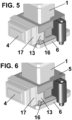
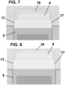
- the figure insert 4 comprises an L-shaped projection 13 which is housed in a complementary hole 16 of the slide body 5 with a gap, which allows the figure insert 4 to move vertically and horizontally, and also to tilt.
- the slide body 5 can be moved from left to right and up and down and tilted.
- the slide body 5 comprises one or more magnets 10, located next to said complementary hole 16.
- This magnet or magnets 10 cause the figure insert 4 to remain in a certain position thanks to the magnetic attraction thereof, and it is precisely this position which prevents friction between the figure insert 4 and the mold cavity during movements thereof, thus avoiding any possible friction that could generate imperfections and generate burrs in the injected part.
- the reason for this freedom of movement is to focus the adjustment of the figure insert 4 of the slide assembly on the figure insert of the mold through a 10° taper lock, which ensures the exact position of the figure insert 4 of the slide assembly.
- the slide assembly is freed from the need for precise and exact positioning, as is usually the case with conventional slide assemblies, thus reducing the need for precision machining and, therefore, eliminating the side guides that in conventional slide assemblies allow the slide assembly to maintain positional accuracy for the subsequent adjustment and assembly of the figure insert.
- the sliding base 6 also comprises a spring-loaded positioning ball 19 to facilitate positioning of the sliding base 6, and a disassembly hole 12 for easy removal with a spanner, which also serves to unscrew a screw located in the sliding stop 9.
- the figure insert 4 comprises beveled side portions 17 and a stop surface 18.
Landscapes
- Engineering & Computer Science (AREA)
- Mechanical Engineering (AREA)
- Manufacturing & Machinery (AREA)
- Moulds For Moulding Plastics Or The Like (AREA)
- Injection Moulding Of Plastics Or The Like (AREA)
- Bearings For Parts Moving Linearly (AREA)
- Physics & Mathematics (AREA)
- Electromagnetism (AREA)
- Power Engineering (AREA)
Claims (13)
- Schieberanordnung für Spritzgießformen, umfassend:- einen Schließkeil (1);- einen Schieberkörper (5), der mit einem Loch versehen ist, um zumindest teilweise den Schließkeil (1) aufzunehmen;- einen Figureneinsatz (4), der mit dem Schieberkörper (5) in Eingriff steht;wobei der Figureneinsatz (4) in einer Gebrauchsposition, in der er mit dem Schieberkörper in Eingriff steht, in Bezug auf den Schieberkörper (5) vertikal und horizontal beweglich ist, wobei der Figureneinsatz (4) einen Vorsprung (13) umfasst, der in einem komplementären Loch (16) des Schieberkörpers (5) untergebracht ist,dadurch gekennzeichnet, dass der Schieberkörper (5) mindestens einen Magneten (10) umfasst, der neben dem komplementären Loch (16) angeordnet ist.
- Schieberanordnung für Spritzgießformen nach Anspruch 1, wobei der Figureneinsatz (4) in der Gebrauchsposition um eine horizontale Achse in Bezug auf den Schieberkörper (5) schwenkbar ist.
- Schieberanordnung für Spritzgießformen nach einem der vorhergehenden Ansprüche, die auch eine Gleitbasis (6) umfasst, auf der der Schieberkörper (5) angeordnet ist, wobei der Schieberkörper (5) auf der Gleitbasis (6) gleitet.
- Schieberanordnung für Spritzgießformen nach einem der vorhergehenden Ansprüche, wobei die Gleitbasis (6) magnetisch ist.
- Schieberanordnung für Spritzgießformen nach einem der vorhergehenden Ansprüche, wobei die Gleitbasis (6) eine Gleitschicht (7) umfasst, die zwischen der Gleitbasis (6) und dem Schieberkörper (5) angeordnet ist.
- Schieberanordnung für Spritzgießformen nach Anspruch 5, wobei die Gleitschicht (7) aus gefülltem Polytetrafluorethylenharz hergestellt ist.
- Schieberanordnung für Spritzgießformen nach einem der vorhergehenden Ansprüche, wobei der Schließkeil (1) einen Hauptteil (14) und einen vorstehenden Teil (15) umfasst, der in dem Loch des Schieberkörpers (5) untergebracht ist.
- Schieberanordnung für Spritzgießformen nach Anspruch 7, wobei der vorstehende Teil (15) mit dem Hauptteil (14) einen spitzen Winkel bildet, der geneigte Flächen definiert, die komplementär zu den durch das Loch definierten geneigten Flächen sind.
- Schieberanordnung für Spritzgießformen nach einem der vorhergehenden Ansprüche, wobei der Schließkeil (1) eine Einstellplatte (2) umfasst, die an seinem vom Schieberkörper (5) am weitesten entfernten Teil angeordnet ist.
- Schieberanordnung für Spritzgießformen nach einem der vorhergehenden Ansprüche, die auch eine Schraube (3) umfasst, die durch den Schließkeil (1) verläuft.
- Schieberanordnung für Spritzgießformen nach einem der vorhergehenden Ansprüche, wobei die Gleitbasis (6) eine Positionierkugel (11) umfasst.
- Schieberanordnung für Spritzgießformen nach einem der vorhergehenden Ansprüche, wobei die Gleitbasis (6) eine Demontageöffnung (12) umfasst.
- Schieberanordnung für Spritzgießformen nach einem der vorhergehenden Ansprüche, wobei der Figureneinsatz (4) abgeschrägte Seitenabschnitte (17) umfasst.
Applications Claiming Priority (1)
| Application Number | Priority Date | Filing Date | Title |
|---|---|---|---|
| ES202230121A ES2948400B2 (es) | 2022-02-16 | 2022-02-16 | Conjunto de corredera para moldes de inyección |
Publications (3)
| Publication Number | Publication Date |
|---|---|
| EP4238737A1 EP4238737A1 (de) | 2023-09-06 |
| EP4238737C0 EP4238737C0 (de) | 2024-07-17 |
| EP4238737B1 true EP4238737B1 (de) | 2024-07-17 |
Family
ID=85222194
Family Applications (1)
| Application Number | Title | Priority Date | Filing Date |
|---|---|---|---|
| EP23382112.3A Active EP4238737B1 (de) | 2022-02-16 | 2023-02-08 | Schiebeanordnung für spritzgussformen |
Country Status (7)
| Country | Link |
|---|---|
| US (1) | US12384080B2 (de) |
| EP (1) | EP4238737B1 (de) |
| JP (1) | JP2023119591A (de) |
| KR (1) | KR20230123446A (de) |
| CN (1) | CN116604784A (de) |
| ES (2) | ES2948400B2 (de) |
| PL (1) | PL4238737T3 (de) |
Citations (1)
| Publication number | Priority date | Publication date | Assignee | Title |
|---|---|---|---|---|
| JPS5941514U (ja) * | 1982-09-11 | 1984-03-17 | 有限会社十和田精工 | 成形装置 |
Family Cites Families (14)
| Publication number | Priority date | Publication date | Assignee | Title |
|---|---|---|---|---|
| US5137442A (en) * | 1991-02-07 | 1992-08-11 | D & L Incorporated | Universal internal core lifter apparatus |
| ES2029186A6 (es) * | 1991-02-25 | 1992-07-16 | Navarra Pruna Alberto | Perfeccionamientos en los medios de bloqueo y deslizamiento para correderas en moldes de inyeccion. |
| JPH09314607A (ja) * | 1996-05-24 | 1997-12-09 | Ricoh Co Ltd | 射出成形用金型の調整方法ならびに金型調整用フィルムおよびその製造方法 |
| US20050098295A1 (en) * | 2002-09-26 | 2005-05-12 | Dubay Richard L. | Universal slide assembly for molding and casting systems |
| JP2004181869A (ja) * | 2002-12-05 | 2004-07-02 | Alps Electric Co Ltd | スライドコア組立体移動構造 |
| JP3936670B2 (ja) * | 2003-04-11 | 2007-06-27 | 東海興業株式会社 | インサート部材を有する樹脂成形品の製造方法及びその製造装置 |
| JP2005138419A (ja) * | 2003-11-06 | 2005-06-02 | Olympus Corp | 射出成形金型及び射出成形方法 |
| US7387505B1 (en) * | 2006-11-24 | 2008-06-17 | Cheng Uei Precision Industry Co., Ltd. | Side-action mechanism and injection mold using the same |
| US20120251020A1 (en) * | 2011-04-04 | 2012-10-04 | Swei Gwo S | Self-Lubricating Structure and Method of Manufacturing the Same |
| PT2716428T (pt) * | 2011-06-01 | 2016-11-04 | Comercial De Utiles Y Moldes Sa | Corrediça deslizante compacta para moldes de injeção |
| DE102013017793B4 (de) * | 2013-10-25 | 2016-03-31 | Pauser und Weinkauf Konstruktion GbR (vertretungsberechtigter Gesellschafter: Günter Pauser, 96052 Bamberg) | Spritzgießwerkzeug |
| CN205522136U (zh) * | 2016-01-25 | 2016-08-31 | 珠海格力电器股份有限公司 | 内模镶件和面板体成型模具 |
| CN111331779B (zh) * | 2020-03-23 | 2022-02-11 | 深圳市凯中精密技术股份有限公司 | 叠层滑块机构 |
| CN212636452U (zh) * | 2020-05-22 | 2021-03-02 | 泉州尚嘉模具有限公司 | 一种塑胶储油杯模具强脱抽芯机构 |
-
2022
- 2022-02-16 ES ES202230121A patent/ES2948400B2/es active Active
-
2023
- 2023-02-08 PL PL23382112.3T patent/PL4238737T3/pl unknown
- 2023-02-08 ES ES23382112T patent/ES2985549T3/es active Active
- 2023-02-08 EP EP23382112.3A patent/EP4238737B1/de active Active
- 2023-02-14 US US18/168,780 patent/US12384080B2/en active Active
- 2023-02-15 KR KR1020230020255A patent/KR20230123446A/ko active Pending
- 2023-02-15 JP JP2023021630A patent/JP2023119591A/ja active Pending
- 2023-02-16 CN CN202310123394.9A patent/CN116604784A/zh active Pending
Patent Citations (1)
| Publication number | Priority date | Publication date | Assignee | Title |
|---|---|---|---|---|
| JPS5941514U (ja) * | 1982-09-11 | 1984-03-17 | 有限会社十和田精工 | 成形装置 |
Also Published As
| Publication number | Publication date |
|---|---|
| JP2023119591A (ja) | 2023-08-28 |
| ES2948400B2 (es) | 2024-01-24 |
| EP4238737A1 (de) | 2023-09-06 |
| EP4238737C0 (de) | 2024-07-17 |
| ES2948400A1 (es) | 2023-09-11 |
| US12384080B2 (en) | 2025-08-12 |
| US20230256658A1 (en) | 2023-08-17 |
| KR20230123446A (ko) | 2023-08-23 |
| PL4238737T3 (pl) | 2025-03-03 |
| CN116604784A (zh) | 2023-08-18 |
| ES2985549T3 (es) | 2024-11-06 |
Similar Documents
| Publication | Publication Date | Title |
|---|---|---|
| US9017062B2 (en) | Compact slide rail for injection molds | |
| CN101835394B (zh) | 用于阀杆致动的凸轮设备及同步阀杆致动的方法 | |
| US5773048A (en) | Retainer for injection molding machine components | |
| US10894347B2 (en) | Device for demolding parts and mold including the device | |
| US4765585A (en) | Slide retainer for injection molds | |
| EP2121267B1 (de) | Formsperre | |
| AU2003237556A1 (en) | Shut-off fitting | |
| EP4238737B1 (de) | Schiebeanordnung für spritzgussformen | |
| US7300271B2 (en) | Injection mold insert block alignment system | |
| HK40100525A (en) | Slide assembly for injection molds | |
| HK40100525B (en) | Slide assembly for injection molds | |
| US20080085337A1 (en) | Retaining device | |
| JP3138562B2 (ja) | ディスク基盤射出成形金型 | |
| CA2989902C (en) | Mold stack for injection molding machine | |
| US20250340002A1 (en) | Slider assembly for injection molds | |
| JPH09141702A (ja) | ディスク射出成形金型の固定側と可動側の円盤キャビティプレートの整列案内装置 | |
| JP3151796B2 (ja) | 金型装置 | |
| US20080128936A1 (en) | External Sprue Bar Position Alignment Method | |
| US11285647B2 (en) | Device for securing and/or releasing injection moulds, means and method | |
| CA3067645C (en) | Device for securing and/or releasing injection moulds, means and method | |
| KR20240054869A (ko) | 사출성형기계용 회전장치 | |
| CN108340542B (zh) | 一种快速定位装置以及注塑机系统 | |
| WO2017188067A1 (ja) | スライド駒の駆動機構 |
Legal Events
| Date | Code | Title | Description |
|---|---|---|---|
| PUAI | Public reference made under article 153(3) epc to a published international application that has entered the european phase |
Free format text: ORIGINAL CODE: 0009012 |
|
| STAA | Information on the status of an ep patent application or granted ep patent |
Free format text: STATUS: THE APPLICATION HAS BEEN PUBLISHED |
|
| AK | Designated contracting states |
Kind code of ref document: A1 Designated state(s): AL AT BE BG CH CY CZ DE DK EE ES FI FR GB GR HR HU IE IS IT LI LT LU LV MC ME MK MT NL NO PL PT RO RS SE SI SK SM TR |
|
| STAA | Information on the status of an ep patent application or granted ep patent |
Free format text: STATUS: REQUEST FOR EXAMINATION WAS MADE |
|
| 17P | Request for examination filed |
Effective date: 20240301 |
|
| RBV | Designated contracting states (corrected) |
Designated state(s): AL AT BE BG CH CY CZ DE DK EE ES FI FR GB GR HR HU IE IS IT LI LT LU LV MC ME MK MT NL NO PL PT RO RS SE SI SK SM TR |
|
| GRAP | Despatch of communication of intention to grant a patent |
Free format text: ORIGINAL CODE: EPIDOSNIGR1 |
|
| STAA | Information on the status of an ep patent application or granted ep patent |
Free format text: STATUS: GRANT OF PATENT IS INTENDED |
|
| REG | Reference to a national code |
Ref country code: HK Ref legal event code: DE Ref document number: 40100525 Country of ref document: HK |
|
| INTG | Intention to grant announced |
Effective date: 20240422 |
|
| GRAS | Grant fee paid |
Free format text: ORIGINAL CODE: EPIDOSNIGR3 |
|
| GRAA | (expected) grant |
Free format text: ORIGINAL CODE: 0009210 |
|
| STAA | Information on the status of an ep patent application or granted ep patent |
Free format text: STATUS: THE PATENT HAS BEEN GRANTED |
|
| AK | Designated contracting states |
Kind code of ref document: B1 Designated state(s): AL AT BE BG CH CY CZ DE DK EE ES FI FR GB GR HR HU IE IS IT LI LT LU LV MC ME MK MT NL NO PL PT RO RS SE SI SK SM TR |
|
| REG | Reference to a national code |
Ref country code: CH Ref legal event code: EP |
|
| REG | Reference to a national code |
Ref country code: DE Ref legal event code: R096 Ref document number: 602023000255 Country of ref document: DE |
|
| REG | Reference to a national code |
Ref country code: IE Ref legal event code: FG4D |
|
| U01 | Request for unitary effect filed |
Effective date: 20240722 |
|
| U07 | Unitary effect registered |
Designated state(s): AT BE BG DE DK EE FI FR IT LT LU LV MT NL PT SE SI Effective date: 20240801 |
|
| REG | Reference to a national code |
Ref country code: ES Ref legal event code: FG2A Ref document number: 2985549 Country of ref document: ES Kind code of ref document: T3 Effective date: 20241106 |
|
| PG25 | Lapsed in a contracting state [announced via postgrant information from national office to epo] |
Ref country code: NO Free format text: LAPSE BECAUSE OF FAILURE TO SUBMIT A TRANSLATION OF THE DESCRIPTION OR TO PAY THE FEE WITHIN THE PRESCRIBED TIME-LIMIT Effective date: 20241017 |
|
| PG25 | Lapsed in a contracting state [announced via postgrant information from national office to epo] |
Ref country code: GR Free format text: LAPSE BECAUSE OF FAILURE TO SUBMIT A TRANSLATION OF THE DESCRIPTION OR TO PAY THE FEE WITHIN THE PRESCRIBED TIME-LIMIT Effective date: 20241018 |
|
| PG25 | Lapsed in a contracting state [announced via postgrant information from national office to epo] |
Ref country code: IS Free format text: LAPSE BECAUSE OF FAILURE TO SUBMIT A TRANSLATION OF THE DESCRIPTION OR TO PAY THE FEE WITHIN THE PRESCRIBED TIME-LIMIT Effective date: 20241117 |
|
| PG25 | Lapsed in a contracting state [announced via postgrant information from national office to epo] |
Ref country code: HR Free format text: LAPSE BECAUSE OF FAILURE TO SUBMIT A TRANSLATION OF THE DESCRIPTION OR TO PAY THE FEE WITHIN THE PRESCRIBED TIME-LIMIT Effective date: 20240717 |
|
| PG25 | Lapsed in a contracting state [announced via postgrant information from national office to epo] |
Ref country code: RS Free format text: LAPSE BECAUSE OF FAILURE TO SUBMIT A TRANSLATION OF THE DESCRIPTION OR TO PAY THE FEE WITHIN THE PRESCRIBED TIME-LIMIT Effective date: 20241017 |
|
| PG25 | Lapsed in a contracting state [announced via postgrant information from national office to epo] |
Ref country code: RS Free format text: LAPSE BECAUSE OF FAILURE TO SUBMIT A TRANSLATION OF THE DESCRIPTION OR TO PAY THE FEE WITHIN THE PRESCRIBED TIME-LIMIT Effective date: 20241017 Ref country code: NO Free format text: LAPSE BECAUSE OF FAILURE TO SUBMIT A TRANSLATION OF THE DESCRIPTION OR TO PAY THE FEE WITHIN THE PRESCRIBED TIME-LIMIT Effective date: 20241017 Ref country code: IS Free format text: LAPSE BECAUSE OF FAILURE TO SUBMIT A TRANSLATION OF THE DESCRIPTION OR TO PAY THE FEE WITHIN THE PRESCRIBED TIME-LIMIT Effective date: 20241117 Ref country code: HR Free format text: LAPSE BECAUSE OF FAILURE TO SUBMIT A TRANSLATION OF THE DESCRIPTION OR TO PAY THE FEE WITHIN THE PRESCRIBED TIME-LIMIT Effective date: 20240717 Ref country code: GR Free format text: LAPSE BECAUSE OF FAILURE TO SUBMIT A TRANSLATION OF THE DESCRIPTION OR TO PAY THE FEE WITHIN THE PRESCRIBED TIME-LIMIT Effective date: 20241018 |
|
| U20 | Renewal fee for the european patent with unitary effect paid |
Year of fee payment: 3 Effective date: 20250121 |
|
| PG25 | Lapsed in a contracting state [announced via postgrant information from national office to epo] |
Ref country code: SM Free format text: LAPSE BECAUSE OF FAILURE TO SUBMIT A TRANSLATION OF THE DESCRIPTION OR TO PAY THE FEE WITHIN THE PRESCRIBED TIME-LIMIT Effective date: 20240717 |
|
| PG25 | Lapsed in a contracting state [announced via postgrant information from national office to epo] |
Ref country code: SK Free format text: LAPSE BECAUSE OF FAILURE TO SUBMIT A TRANSLATION OF THE DESCRIPTION OR TO PAY THE FEE WITHIN THE PRESCRIBED TIME-LIMIT Effective date: 20240717 |
|
| PLBE | No opposition filed within time limit |
Free format text: ORIGINAL CODE: 0009261 |
|
| STAA | Information on the status of an ep patent application or granted ep patent |
Free format text: STATUS: NO OPPOSITION FILED WITHIN TIME LIMIT |
|
| 26N | No opposition filed |
Effective date: 20250422 |
|
| PGFP | Annual fee paid to national office [announced via postgrant information from national office to epo] |
Ref country code: ES Payment date: 20250423 Year of fee payment: 3 |
|
| PG25 | Lapsed in a contracting state [announced via postgrant information from national office to epo] |
Ref country code: MC Free format text: LAPSE BECAUSE OF FAILURE TO SUBMIT A TRANSLATION OF THE DESCRIPTION OR TO PAY THE FEE WITHIN THE PRESCRIBED TIME-LIMIT Effective date: 20240717 |
|
| PG25 | Lapsed in a contracting state [announced via postgrant information from national office to epo] |
Ref country code: IE Free format text: LAPSE BECAUSE OF NON-PAYMENT OF DUE FEES Effective date: 20250208 |
|
| U20 | Renewal fee for the european patent with unitary effect paid |
Year of fee payment: 4 Effective date: 20260120 |
|
| PG25 | Lapsed in a contracting state [announced via postgrant information from national office to epo] |
Ref country code: RO Free format text: LAPSE BECAUSE OF FAILURE TO SUBMIT A TRANSLATION OF THE DESCRIPTION OR TO PAY THE FEE WITHIN THE PRESCRIBED TIME-LIMIT Effective date: 20240717 |
|
| PGFP | Annual fee paid to national office [announced via postgrant information from national office to epo] |
Ref country code: TR Payment date: 20260203 Year of fee payment: 4 |
|
| PGFP | Annual fee paid to national office [announced via postgrant information from national office to epo] |
Ref country code: CZ Payment date: 20260203 Year of fee payment: 4 |
|
| PGFP | Annual fee paid to national office [announced via postgrant information from national office to epo] |
Ref country code: PL Payment date: 20260120 Year of fee payment: 4 |