EP4238631A1 - Procédé et dispositif de séparation de gaz - Google Patents
Procédé et dispositif de séparation de gaz Download PDFInfo
- Publication number
- EP4238631A1 EP4238631A1 EP21886149.0A EP21886149A EP4238631A1 EP 4238631 A1 EP4238631 A1 EP 4238631A1 EP 21886149 A EP21886149 A EP 21886149A EP 4238631 A1 EP4238631 A1 EP 4238631A1
- Authority
- EP
- European Patent Office
- Prior art keywords
- gas
- membrane
- membrane module
- gas separation
- pressure
- Prior art date
- Legal status (The legal status is an assumption and is not a legal conclusion. Google has not performed a legal analysis and makes no representation as to the accuracy of the status listed.)
- Pending
Links
- 238000000926 separation method Methods 0.000 title claims abstract description 132
- 239000012528 membrane Substances 0.000 claims abstract description 181
- 239000000203 mixture Substances 0.000 claims abstract description 36
- 239000012466 permeate Substances 0.000 claims abstract description 29
- VNWKTOKETHGBQD-UHFFFAOYSA-N methane Chemical group C VNWKTOKETHGBQD-UHFFFAOYSA-N 0.000 claims description 69
- 239000002360 explosive Substances 0.000 claims description 16
- 239000007789 gas Substances 0.000 description 154
- 239000000758 substrate Substances 0.000 description 37
- VYPSYNLAJGMNEJ-UHFFFAOYSA-N Silicium dioxide Chemical compound O=[Si]=O VYPSYNLAJGMNEJ-UHFFFAOYSA-N 0.000 description 28
- 239000002808 molecular sieve Substances 0.000 description 27
- URGAHOPLAPQHLN-UHFFFAOYSA-N sodium aluminosilicate Chemical compound [Na+].[Al+3].[O-][Si]([O-])=O.[O-][Si]([O-])=O URGAHOPLAPQHLN-UHFFFAOYSA-N 0.000 description 27
- HNPSIPDUKPIQMN-UHFFFAOYSA-N dioxosilane;oxo(oxoalumanyloxy)alumane Chemical compound O=[Si]=O.O=[Al]O[Al]=O HNPSIPDUKPIQMN-UHFFFAOYSA-N 0.000 description 26
- 239000010457 zeolite Substances 0.000 description 25
- 229910021536 Zeolite Inorganic materials 0.000 description 24
- CURLTUGMZLYLDI-UHFFFAOYSA-N Carbon dioxide Chemical compound O=C=O CURLTUGMZLYLDI-UHFFFAOYSA-N 0.000 description 21
- 238000000034 method Methods 0.000 description 19
- 230000002093 peripheral effect Effects 0.000 description 19
- 229910002092 carbon dioxide Inorganic materials 0.000 description 15
- 239000000377 silicon dioxide Substances 0.000 description 13
- 239000011148 porous material Substances 0.000 description 12
- 239000000463 material Substances 0.000 description 11
- QVGXLLKOCUKJST-UHFFFAOYSA-N atomic oxygen Chemical group [O] QVGXLLKOCUKJST-UHFFFAOYSA-N 0.000 description 8
- 239000000919 ceramic Substances 0.000 description 7
- OKTJSMMVPCPJKN-UHFFFAOYSA-N Carbon Chemical compound [C] OKTJSMMVPCPJKN-UHFFFAOYSA-N 0.000 description 6
- 229910052799 carbon Inorganic materials 0.000 description 6
- 239000001569 carbon dioxide Substances 0.000 description 6
- 239000001301 oxygen Substances 0.000 description 5
- 229910052760 oxygen Inorganic materials 0.000 description 5
- 239000002243 precursor Substances 0.000 description 5
- PNEYBMLMFCGWSK-UHFFFAOYSA-N Alumina Chemical compound [O-2].[O-2].[O-2].[Al+3].[Al+3] PNEYBMLMFCGWSK-UHFFFAOYSA-N 0.000 description 4
- IJGRMHOSHXDMSA-UHFFFAOYSA-N Atomic nitrogen Chemical compound N#N IJGRMHOSHXDMSA-UHFFFAOYSA-N 0.000 description 4
- 239000002028 Biomass Substances 0.000 description 4
- 230000015572 biosynthetic process Effects 0.000 description 4
- 238000001514 detection method Methods 0.000 description 4
- 230000000694 effects Effects 0.000 description 4
- CSCPPACGZOOCGX-UHFFFAOYSA-N Acetone Chemical compound CC(C)=O CSCPPACGZOOCGX-UHFFFAOYSA-N 0.000 description 3
- LFQSCWFLJHTTHZ-UHFFFAOYSA-N Ethanol Chemical compound CCO LFQSCWFLJHTTHZ-UHFFFAOYSA-N 0.000 description 3
- OKKJLVBELUTLKV-UHFFFAOYSA-N Methanol Chemical compound OC OKKJLVBELUTLKV-UHFFFAOYSA-N 0.000 description 3
- 230000007423 decrease Effects 0.000 description 3
- 230000001771 impaired effect Effects 0.000 description 3
- 229910052751 metal Inorganic materials 0.000 description 3
- 239000002184 metal Substances 0.000 description 3
- XLYOFNOQVPJJNP-UHFFFAOYSA-N water Chemical class O XLYOFNOQVPJJNP-UHFFFAOYSA-N 0.000 description 3
- GHOKWGTUZJEAQD-ZETCQYMHSA-N (D)-(+)-Pantothenic acid Chemical compound OCC(C)(C)[C@@H](O)C(=O)NCCC(O)=O GHOKWGTUZJEAQD-ZETCQYMHSA-N 0.000 description 2
- QGZKDVFQNNGYKY-UHFFFAOYSA-N Ammonia Chemical compound N QGZKDVFQNNGYKY-UHFFFAOYSA-N 0.000 description 2
- ATUOYWHBWRKTHZ-UHFFFAOYSA-N Propane Chemical compound CCC ATUOYWHBWRKTHZ-UHFFFAOYSA-N 0.000 description 2
- WYURNTSHIVDZCO-UHFFFAOYSA-N Tetrahydrofuran Chemical compound C1CCOC1 WYURNTSHIVDZCO-UHFFFAOYSA-N 0.000 description 2
- GWEVSGVZZGPLCZ-UHFFFAOYSA-N Titan oxide Chemical compound O=[Ti]=O GWEVSGVZZGPLCZ-UHFFFAOYSA-N 0.000 description 2
- MCMNRKCIXSYSNV-UHFFFAOYSA-N Zirconium dioxide Chemical compound O=[Zr]=O MCMNRKCIXSYSNV-UHFFFAOYSA-N 0.000 description 2
- 229910052796 boron Inorganic materials 0.000 description 2
- 238000010586 diagram Methods 0.000 description 2
- KZHJGOXRZJKJNY-UHFFFAOYSA-N dioxosilane;oxo(oxoalumanyloxy)alumane Chemical compound O=[Si]=O.O=[Si]=O.O=[Al]O[Al]=O.O=[Al]O[Al]=O.O=[Al]O[Al]=O KZHJGOXRZJKJNY-UHFFFAOYSA-N 0.000 description 2
- 229910052733 gallium Inorganic materials 0.000 description 2
- 238000010438 heat treatment Methods 0.000 description 2
- 239000011261 inert gas Substances 0.000 description 2
- 229910052742 iron Inorganic materials 0.000 description 2
- 239000010410 layer Substances 0.000 description 2
- 229910052863 mullite Inorganic materials 0.000 description 2
- 229910052757 nitrogen Inorganic materials 0.000 description 2
- 229920000642 polymer Polymers 0.000 description 2
- 238000011084 recovery Methods 0.000 description 2
- 229910052710 silicon Inorganic materials 0.000 description 2
- 239000010703 silicon Substances 0.000 description 2
- 238000003980 solgel method Methods 0.000 description 2
- 239000011269 tar Substances 0.000 description 2
- 229910052718 tin Inorganic materials 0.000 description 2
- 229910052719 titanium Inorganic materials 0.000 description 2
- 229910052725 zinc Inorganic materials 0.000 description 2
- 229910052726 zirconium Inorganic materials 0.000 description 2
- 235000017166 Bambusa arundinacea Nutrition 0.000 description 1
- 235000017491 Bambusa tulda Nutrition 0.000 description 1
- 241001330002 Bambuseae Species 0.000 description 1
- 239000004215 Carbon black (E152) Substances 0.000 description 1
- OTMSDBZUPAUEDD-UHFFFAOYSA-N Ethane Chemical compound CC OTMSDBZUPAUEDD-UHFFFAOYSA-N 0.000 description 1
- SECXISVLQFMRJM-UHFFFAOYSA-N N-Methylpyrrolidone Chemical compound CN1CCCC1=O SECXISVLQFMRJM-UHFFFAOYSA-N 0.000 description 1
- 235000015334 Phyllostachys viridis Nutrition 0.000 description 1
- 239000004642 Polyimide Substances 0.000 description 1
- 229920001328 Polyvinylidene chloride Polymers 0.000 description 1
- 229910052581 Si3N4 Inorganic materials 0.000 description 1
- 238000005299 abrasion Methods 0.000 description 1
- 150000004703 alkoxides Chemical class 0.000 description 1
- 229910000323 aluminium silicate Inorganic materials 0.000 description 1
- 229910021529 ammonia Inorganic materials 0.000 description 1
- 125000003118 aryl group Chemical group 0.000 description 1
- 230000004323 axial length Effects 0.000 description 1
- 239000011425 bamboo Substances 0.000 description 1
- 239000011230 binding agent Substances 0.000 description 1
- 239000003575 carbonaceous material Substances 0.000 description 1
- 239000003795 chemical substances by application Substances 0.000 description 1
- 239000003245 coal Substances 0.000 description 1
- 239000011248 coating agent Substances 0.000 description 1
- 238000000576 coating method Methods 0.000 description 1
- 238000009833 condensation Methods 0.000 description 1
- 230000005494 condensation Effects 0.000 description 1
- 230000008602 contraction Effects 0.000 description 1
- 230000018044 dehydration Effects 0.000 description 1
- 238000006297 dehydration reaction Methods 0.000 description 1
- 238000009792 diffusion process Methods 0.000 description 1
- 238000003618 dip coating Methods 0.000 description 1
- 238000001035 drying Methods 0.000 description 1
- 238000004880 explosion Methods 0.000 description 1
- 238000000855 fermentation Methods 0.000 description 1
- 230000004151 fermentation Effects 0.000 description 1
- 235000013305 food Nutrition 0.000 description 1
- 239000011521 glass Substances 0.000 description 1
- 230000005484 gravity Effects 0.000 description 1
- 229910052736 halogen Inorganic materials 0.000 description 1
- 150000002367 halogens Chemical class 0.000 description 1
- 239000012510 hollow fiber Substances 0.000 description 1
- 229930195733 hydrocarbon Natural products 0.000 description 1
- 150000002430 hydrocarbons Chemical class 0.000 description 1
- 239000001257 hydrogen Substances 0.000 description 1
- 229910052739 hydrogen Inorganic materials 0.000 description 1
- 150000002431 hydrogen Chemical class 0.000 description 1
- 230000007062 hydrolysis Effects 0.000 description 1
- 238000006460 hydrolysis reaction Methods 0.000 description 1
- 229910010272 inorganic material Inorganic materials 0.000 description 1
- 239000011147 inorganic material Substances 0.000 description 1
- 229920005610 lignin Polymers 0.000 description 1
- 244000144972 livestock Species 0.000 description 1
- QSHDDOUJBYECFT-UHFFFAOYSA-N mercury Chemical compound [Hg] QSHDDOUJBYECFT-UHFFFAOYSA-N 0.000 description 1
- 229910052753 mercury Inorganic materials 0.000 description 1
- 150000002739 metals Chemical class 0.000 description 1
- 230000004048 modification Effects 0.000 description 1
- 238000012986 modification Methods 0.000 description 1
- 239000003345 natural gas Substances 0.000 description 1
- 229920000368 omega-hydroxypoly(furan-2,5-diylmethylene) polymer Polymers 0.000 description 1
- 239000003960 organic solvent Substances 0.000 description 1
- 125000004430 oxygen atom Chemical group O* 0.000 description 1
- 239000005011 phenolic resin Substances 0.000 description 1
- 229920001568 phenolic resin Polymers 0.000 description 1
- 229910052698 phosphorus Inorganic materials 0.000 description 1
- 229920001721 polyimide Polymers 0.000 description 1
- -1 polypyrrolones Polymers 0.000 description 1
- 229920001709 polysilazane Polymers 0.000 description 1
- 238000002459 porosimetry Methods 0.000 description 1
- 239000001294 propane Substances 0.000 description 1
- 229920005989 resin Polymers 0.000 description 1
- 239000011347 resin Substances 0.000 description 1
- 239000010801 sewage sludge Substances 0.000 description 1
- HBMJWWWQQXIZIP-UHFFFAOYSA-N silicon carbide Chemical compound [Si+]#[C-] HBMJWWWQQXIZIP-UHFFFAOYSA-N 0.000 description 1
- 229910010271 silicon carbide Inorganic materials 0.000 description 1
- HQVNEWCFYHHQES-UHFFFAOYSA-N silicon nitride Chemical compound N12[Si]34N5[Si]62N3[Si]51N64 HQVNEWCFYHHQES-UHFFFAOYSA-N 0.000 description 1
- 229910052814 silicon oxide Inorganic materials 0.000 description 1
- 239000002356 single layer Substances 0.000 description 1
- 239000002002 slurry Substances 0.000 description 1
- 239000002904 solvent Substances 0.000 description 1
- 239000000126 substance Substances 0.000 description 1
- 238000003786 synthesis reaction Methods 0.000 description 1
- 239000013076 target substance Substances 0.000 description 1
- YLQBMQCUIZJEEH-UHFFFAOYSA-N tetrahydrofuran Natural products C=1C=COC=1 YLQBMQCUIZJEEH-UHFFFAOYSA-N 0.000 description 1
- 239000002699 waste material Substances 0.000 description 1
- 239000002023 wood Substances 0.000 description 1
- RUDFQVOCFDJEEF-UHFFFAOYSA-N yttrium(III) oxide Inorganic materials [O-2].[O-2].[O-2].[Y+3].[Y+3] RUDFQVOCFDJEEF-UHFFFAOYSA-N 0.000 description 1
Images
Classifications
-
- B—PERFORMING OPERATIONS; TRANSPORTING
- B01—PHYSICAL OR CHEMICAL PROCESSES OR APPARATUS IN GENERAL
- B01D—SEPARATION
- B01D53/00—Separation of gases or vapours; Recovering vapours of volatile solvents from gases; Chemical or biological purification of waste gases, e.g. engine exhaust gases, smoke, fumes, flue gases, aerosols
- B01D53/22—Separation of gases or vapours; Recovering vapours of volatile solvents from gases; Chemical or biological purification of waste gases, e.g. engine exhaust gases, smoke, fumes, flue gases, aerosols by diffusion
-
- B—PERFORMING OPERATIONS; TRANSPORTING
- B01—PHYSICAL OR CHEMICAL PROCESSES OR APPARATUS IN GENERAL
- B01D—SEPARATION
- B01D53/00—Separation of gases or vapours; Recovering vapours of volatile solvents from gases; Chemical or biological purification of waste gases, e.g. engine exhaust gases, smoke, fumes, flue gases, aerosols
- B01D53/30—Controlling by gas-analysis apparatus
-
- C—CHEMISTRY; METALLURGY
- C07—ORGANIC CHEMISTRY
- C07C—ACYCLIC OR CARBOCYCLIC COMPOUNDS
- C07C7/00—Purification; Separation; Use of additives
- C07C7/144—Purification; Separation; Use of additives using membranes, e.g. selective permeation
-
- B—PERFORMING OPERATIONS; TRANSPORTING
- B01—PHYSICAL OR CHEMICAL PROCESSES OR APPARATUS IN GENERAL
- B01D—SEPARATION
- B01D2256/00—Main component in the product gas stream after treatment
- B01D2256/24—Hydrocarbons
- B01D2256/245—Methane
-
- B—PERFORMING OPERATIONS; TRANSPORTING
- B01—PHYSICAL OR CHEMICAL PROCESSES OR APPARATUS IN GENERAL
- B01D—SEPARATION
- B01D2257/00—Components to be removed
- B01D2257/50—Carbon oxides
- B01D2257/504—Carbon dioxide
-
- B—PERFORMING OPERATIONS; TRANSPORTING
- B01—PHYSICAL OR CHEMICAL PROCESSES OR APPARATUS IN GENERAL
- B01D—SEPARATION
- B01D2257/00—Components to be removed
- B01D2257/70—Organic compounds not provided for in groups B01D2257/00 - B01D2257/602
- B01D2257/702—Hydrocarbons
- B01D2257/7022—Aliphatic hydrocarbons
- B01D2257/7025—Methane
-
- B—PERFORMING OPERATIONS; TRANSPORTING
- B01—PHYSICAL OR CHEMICAL PROCESSES OR APPARATUS IN GENERAL
- B01D—SEPARATION
- B01D2258/00—Sources of waste gases
- B01D2258/05—Biogas
Definitions
- the present invention relates to a method and an apparatus for separating combustible components from a gas that contains combustible components, by using a selective gas-permeable membrane (hereinafter also referred to as a "membrane").
- a selective gas-permeable membrane hereinafter also referred to as a "membrane”
- Membrane separation is a commonly used technique for separating a gas that contains combustible components, such as methane, into combustible components and other gas components (e.g., Patent Literature 1 and 2).
- Separatation performance refers to selectivity for combustible gases and non-combustible gases. Consequently, a permeate side has a high proportion of combustible gases. In instances where the concentration of combustible gases is high, if air from the outside is inadvertently introduced through a leak, the permeate side becomes within an explosive range easily.
- Patent Literature 2 describes a method for separating a combustible organic vapor-containing exhaust gas with a membrane; in the method, to avoid an explosive range, an inert gas is passed on a permeate side through which a combustible organic vapor permeates.
- inorganic membranes since they typically have high separation performance, a content of the substance that is selectively separated decreases in later stages of separation. As a result, a partial pressure that serves as a driving force for the separation decreases, which results in an extremely low amount of the gas that permeates. Accordingly, typically, it is necessary to increase the pressure of the non-permeate side or reduce the pressure of the permeate side, in order to increase the difference in the partial pressure between the permeate side and the non-permeate side of the membrane. In the instance where the pressure is increased, power used for a compressor or the like increases, which is economically disadvantageous.
- an object of the present invention is to provide a gas separation method and a gas separation apparatus for performing, by using a membrane module, a membrane separation treatment on a gas that contains combustible components; the method and the apparatus are designed to immediately stop the operation of the membrane module in instances in which a combustible component is inadvertently introduced into the permeate gas.
- the gas separation method and the gas separation apparatus of the present invention enable the operation of a membrane module to be immediately stopped in instances in which a combustible component is inadvertently introduced into the permeate gas.
- the treatment target gas contains one or more combustible components and one or more non-combustible components.
- the combustible components include, but are not limited to, hydrocarbon gases, such as methane, ethane, and propane, hydrogen, and ammonia.
- the non-combustible components include, but are not limited to, carbon dioxide gas (CO 2 ), nitrogen, and halogen gas.
- the source gas containing such combustible components and non-combustible components include, but are not limited to, biogases, landfill gases, hot spring gases, coal mine gases, and natural gases.
- biogas is a gas produced by methane fermentation of biomass and may be subclassified as follows: a biogas produced from landfill-derived biomass may be referred to as a "landfill gas", a biogas produced from sewage sludge-derived biomass as a "digester gas”, and a biogas produced from food waste- or livestock waste-derived biomass as a "biogas".
- the concentration of combustible components in the source gas is, approximately, 30 to 70% (vol.%, the same applies hereinafter) for biogases, 20 to 70% for landfill gases, depending on how the gases were collected, and 10 to 90% in terms of methane for hot spring gases, where the composition is one in which the concentration of saturated water vapor is not taken into account.
- the concentration of combustible components in the source gas be 20 to 95%.
- a membrane module include a membrane module that includes a large number of tubular separation membranes disposed in a vessel and in which a source gas can be passed through an outer side of the tubular separation membranes, and non-combustible components can be allowed to permeate into an inner side of the tubular separation membranes or in which a source gas can be passed through the inner side of the tubular separation membranes, and non-combustible components can be allowed to permeate to the outer side of the tubular separation membranes.
- These are not intended to be limiting and can be applied to a honeycomb structure, a hollow fiber structure, a sheet structure, and the like.
- the tubular separation membranes are those that include a molecular sieve membrane, which serves as a selective gas-permeable membrane, disposed on an inner peripheral surface and/or an outer peripheral surface of tubular porous substrates.
- a molecular sieve membrane which serves as a selective gas-permeable membrane
- the porous substrate serves as a support for supporting the molecular sieve membrane.
- the material that forms the porous substrate is not particularly limited, and any of a variety of materials, such as glass, ceramics, metals, formed carbon materials, and resins, can be employed. In the instance of ceramic supports, any ceramic may be used as long as the ceramic is a chemically stable porous inorganic material that enables the formation of a crystallized zeolite in the form of a membrane, on a surface or the like of the material.
- the ceramic may be, for example, a ceramic sintered body made of, for instance, silica, ⁇ -alumina, ⁇ -alumina, mullite, zirconia, titania, yttria, silicon nitride, silicon carbide, or the like.
- aluminas such as ⁇ -alumina and ⁇ -alumina, and mullite are preferable, and aluminas are particularly preferable.
- the support can be easily partially transformed into a zeolite, and, consequently, strong bonding between the support and the zeolite is achieved, which facilitates the formation of a membrane that is dense and has a high separation performance.
- the porous substrate itself need not have the functions of a molecular sieve.
- the porous substrate has small pores (voids, vacancies) interconnecting an outer wall side (outer peripheral surface) and an inner wall side (inner peripheral surface).
- the porous substrate has a porosity that is typically greater than or equal to 20%, preferably greater than or equal to 25%, and more preferably greater than or equal to 30% and is typically less than or equal to 80%, preferably less than or equal to 60%, and more preferably less than or equal to 50%.
- An average pore diameter of the porous substrate is typically greater than or equal to 0.01 um, preferably greater than or equal to 0.05 um, and more preferably greater than or equal to 0.1 um, and the upper limit thereof is typically less than or equal to 20 ⁇ m, preferably less than or equal to 10 ⁇ m, and more preferably less than or equal to 5 um.
- the porous substrate When the porous substrate has such pores, the porous substrate has sufficient strength and, therefore, can appropriately support the molecular sieve membrane; in addition, the porous substrate can allow permeation therethrough, at a sufficient speed, of the molecules that have permeated through the molecular sieve membrane, and the porous substrate can also allow molecules to reach the molecular sieve membrane at a sufficient speed.
- the porosity and the pore diameter of the porous substrate can be easily determined, for instance, by mercury intrusion porosimetry or by SEM examination of a cross section. The average pore diameter can be determined in a similar manner. Alternatively, the average pore diameter can be calculated from a volume and a mass, based on a true specific gravity.
- the porous substrate is one in which the openings of the pores extending from the outer peripheral surface to the inner peripheral surface have a maximum diameter that is typically less than or equal to 10 ⁇ m and preferably less than or equal to 8 um.
- the lower limit of the maximum diameter is greater than or equal to 0.05 um.
- the portions extending from the outer peripheral surface to the inner peripheral surface may have a pore diameter that is entirely uniform or have a pore diameter that varies locally or progressively, as described in JP 2005-270887 A , for example.
- a thickness (difference between a radius of the outer peripheral surface and a radius of the inner peripheral surface) of the tubular porous substrate is not particularly limited.
- the thickness is preferably greater than or equal to 0.5 mm, more preferably greater than or equal to 0.8 mm, and even more preferably greater than or equal to 1.0 mm, depending on the material, the porosity, and the like.
- An inner diameter of the tubular porous substrate is not particularly limited.
- a ratio of the inner diameter (diameter) to the above-mentioned thickness of the porous substrate is preferably less than or equal to 20, more preferably less than or equal to 17, even more preferably less than or equal to 13, and particularly preferably less than or equal to 9, depending on the material, the porosity, and the like.
- the inner diameter be greater than or equal to 3 mm, particularly, greater than or equal to 5 mm, and less than or equal to 20 mm, particularly, less than or equal to 15 mm.
- a length (axial length) of the porous substrate is not particularly limited.
- the molecular sieve membrane is formed on the outer peripheral surface and/or the inner peripheral surface of the porous substrate.
- the molecular sieve membrane may have any form as long as the molecular sieve membrane can appropriately perform the functions of the molecular sieve.
- the molecular sieve membrane may either be an organic membrane or an inorganic membrane.
- the molecular sieve membrane is an inorganic membrane.
- the inorganic membrane is a zeolite membrane, a silica membrane, a carbon membrane, or a combination thereof.
- a zeolite membrane or a silica membrane is preferable.
- a zeolite membrane is preferable from the standpoint of separation performance, water resistance, and durability.
- the zeolite be an aluminosilicate; alternatively, it is also possible that a metal element, such as Ga, Fe, B, Ti, Zr, Sn, or Zn, be used instead of Al, or an element, such as Ga, Fe, B, Ti, Zr, Sn, Zn, or P, be included together with Al, provided that the performance of the membrane is not significantly impaired.
- a metal element such as Ga, Fe, B, Ti, Zr, Sn, Zn, or P, be included together with Al, provided that the performance of the membrane is not significantly impaired.
- the framework of the crystalline zeolite that forms the pores of the zeolite membrane is an 8- or less-membered oxygen ring. More preferably, the framework is a 6- to 8-membered oxygen ring.
- Examples of the structure of the zeolite include AEI, AFG, ANA, CHA, DDR, EAB, ERI, ESV, FAR, FRA, GIS, ITE, KFI, LEV, LIO, LOS, LTA, LTN, MAR, MWF, PAU, RHO, RTH, SOD, STI, TOL, and UFI.
- a membrane formed of a zeolite of a type of AEI, CHA, DDR, ERI, KFI, LEV, MWF, PAU, RHO, RTH, SOD, LTA, or UFI it is more preferable to use a membrane formed of a zeolite of a type of CHA, DDR, MWF, RHO, or SOD.
- zeolites having an n-membered oxygen ring the value of n represents the number of oxygen atoms that is highest among those of the pores formed by the zeolite framework and T elements (elements other than oxygen that form the framework).
- an organic template (structure-directing agent) may be used if necessary.
- the template is not particularly limited as long as the template enables the formation of the desired zeolite structure, and, if the synthesis can be achieved without any template, there is no need to use a template.
- a content of silica in the silica membrane is not particularly limited as long as the effects of the present invention are not significantly impaired.
- a proportion of silicon to all electropositive elements including silicon is typically greater than or equal to 50 mol%, in a silicon oxide composition.
- the silica membrane is formed on an inorganic porous substrate with a sol-gel process, a CVD process, a polymer precursor process, or the like.
- the silica membrane can be formed by reacting a metal alkoxide with water on an inorganic porous substrate to cause hydrolysis and dehydration condensation, thereby forming a gel.
- the silica membrane can be formed, for example, as follows: in instances where the inorganic porous substrate is a porous tubular substrate, oxygen is passed through the inner side, and a silica source through the outer side, to deposit an amorphous silica layer within the pores of the substrate.
- the silica membrane can be formed by applying a silica precursor, such as an alkoxysilane or a polysilazane, to an inorganic porous substrate and subsequently performing a heat treatment thereon.
- a silica precursor such as an alkoxysilane or a polysilazane
- the carbon membrane is formed by dip coating (immersion-coating) a carbon membrane precursor solution onto a porous substrate, performing a heat treatment thereon at a temperature of approximately 600 to 800°C, and drying the resultant.
- the carbon membrane precursor include aromatic polyimides, polypyrrolones, polyfurfuryl alcohols, polyvinylidene chlorides, phenolic resins, lignin derivatives, wood tars, and bamboo tars.
- a preferred solvent that may be used is an organic solvent, such as tetrahydrofuran, acetone, methanol, ethanol, or N-methylpyrrolidone.
- a thickness of the molecular sieve membrane is not particularly limited.
- the lower limit of the thickness is typically greater than or equal to 0.01 um.
- the upper limit of the thickness is preferably less than or equal to 30 um and more preferably less than or equal to 10 um.
- the membranes may be formed of a single layer or two or more layers, and the thickness of the membranes is preferably greater than or equal to 1 nm.
- the thickness is preferably less than or equal to 10 um and more preferably less than or equal to 1 um.
- the thickness thereof is preferably greater than or equal to 0.05 ⁇ m and more preferably greater than or equal to 0.1 um.
- the upper limit of the thickness is preferably less than or equal to 5 mm and more preferably less than or equal to 500 um. It is preferable that the thickness of the membrane be small, provided that the performance of the membrane is not significantly impaired.
- Methods for forming the molecular sieve membrane on a surface of the porous substrate are not limited to the methods described above. Examples of the methods include (1) a method in which a material that can form a molecular sieve membrane is firmly attached to a surface of a porous substrate with a binder or the like; (2) a method in which a porous substrate is impregnated with a slurry or a solution in which a material that can form a molecular sieve membrane is dispersed or dissolved, to cause the material to be firmly attached to a surface of the porous substrate; and (3) a method in which a material (in particular, for a zeolite) that can form a molecular sieve membrane is crystallized in the form of a membrane on a surface of a porous substrate (see, for example, the pamphlet of WO 2013/125660 A1 , and the like).
- the molecular sieve membrane may be formed only on the outer peripheral surface of the porous substrate; the molecular sieve membrane may be formed only on the inner peripheral surface of the porous substrate; or the molecular sieve membrane may be formed on both the outer peripheral surface and the inner peripheral surface of the porous substrate. Any of these forms may be employed. Typically, from the standpoint of an internal contraction force possessed by the coated member, it is desirable that the molecular sieve membrane be formed on the outer peripheral surface of the porous substrate.
- a separation factor ⁇ of the membrane is greater than or equal to 80, preferably greater than or equal to 100, and particularly preferably greater than or equal to 150.
- the separation factor ⁇ may vary depending on separation conditions.
- the separation factor ⁇ is defined as each of the values obtained under the separation conditions of the separation operations performed by the respective membrane modules.
- a secondary side (permeate side) of the membrane module is depressurized with a vacuum pump so that the pressure can become lower than the atmospheric pressure. Furthermore, a composition, a pressure, a flow rate, and the like of the gas of the secondary side are analyzed by performing detection on-line or in-line, and the supply of the source gas and the vacuum pump are stopped in the following instances: instances in which the composition of the gas of the secondary side enters a specified range (e.g., a range of the concentration of combustible components of greater than 20 vol.% or an explosive range) as a result of, for instance, damage, such as breakage, in the membrane; instances in which the concentration of oxygen of the secondary side enters a specified range (e.g., a range of greater than 1 vol.% or an explosive range); and/or instances in which at least one of the pressure and the flow rate, of the gas of the secondary side, exceeds a reference value. Additionally, valves installed on a source gas entry side and a
- the specified range can be entered for various reasons. The most likely reason is believed to be inadvertent introduction of the source gas. Inadvertent introduction of the source gas can occur in instances in which the separation membrane is broken during the separation operation or in instances in which a seal of the separation membrane becomes insufficient.
- the reference value of the pressure of the gas of the secondary side is, for example, a value 10 kPa higher than a default value or a value of a degree of depressurization specified for a secondary side 4b. Furthermore, the reference value of the flow rate of the gas of the secondary side is, for example, a value 50% higher than a default value.
- umps are stopped means that the supply of the source gas and depressurization are stopped; this encompasses cases in which a state, such as an idling state, is created in which the supply of a material, pressurization, and depressurization by the pumps are not performed.
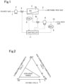
- Fig. 1 illustrates an example of a gas separation apparatus equipped with a membrane module.
- the source gas containing combustible components is introduced into a primary side 4a of a membrane module 4 through a tube 1, which includes a pressure pump 2 and a valve (emergency shut-off valve) 3.
- a membrane 4m divides the interior of the membrane module 4 into the primary side 4a and the secondary side 4b.
- the source gas contains methane (CH 4 ), which is a combustible component, and carbon dioxide gas (CO 2 ), which is a non-combustible component, and the membrane 4m is a zeolite membrane.
- CH 4 methane
- CO 2 carbon dioxide gas
- the membrane 4m is a zeolite membrane.
- Carbon dioxide gas can permeate through the zeolite membrane 4m, and methane cannot substantially permeate through the zeolite membrane 4m.
- a primary side exit gas which is methane-rich, flows out to a tube 5 from a primary side outlet of the membrane module 4.
- a tube 10 is connected to the secondary side 4b of the membrane module 4.
- the tube 10 includes a pressure sensor 6, a valve (emergency shut-off valve) 7, a vacuum pump 8, and a methane sensor 9 for detecting a concentration of methane.
- the secondary side 4b has a reduced pressure less than or equal to a specified degree of depressurization.
- the reduced pressure is preferably less than or equal to -30 kPaG and particularly preferably less than or equal to -50 kPaG.
- the sensor is not limited to methane sensors, and any means capable of detecting the composition may be used.
- a gas sensor operable in a known manner may be used.
- the use of a methane sensor is preferable from the standpoint of detecting the combustible gas.
- Carbon dioxide gas permeates through the zeolite membrane 4m and is drawn as a CO 2 rich gas through the tube 10.
- a controller 11 is configured to include detection signals input from the pressure sensor 6 and the methane sensor 9.
- the controller 11 is configured to stop the pumps 2 and 8 and close the valves 3 and 7 in an emergency.
- the stopping operation for emergencies is not limited to the stopping of the pumps, and any other operation that stops the separation operation may be employed.
- An amount of supply of the source gas per unit time is such that CO 2 is in an amount of 40 molar parts, and CH 4 is in an amount of 60 molar parts.
- the source gas is pressurized to 600 kPaG with the pressure pump 2 and supplied to the membrane module 4.
- An amount of exit of the methane-rich gas, which is the primary side exit gas, per unit time is such that CO 2 is in an amount of 3 molar parts, and CH 4 is in an amount of 58 molar parts, provided that an absolute pressure of the permeate side of the membrane is reduced to -30 kPaG, a permeance for CO 2 is 2.0E-06 mol/m 2 /Pa/s, an area of the membrane is 2.6 m 2 , and the separation factor ⁇ of the membrane is 83.
- An amount of exit of the CO 2 -rich gas, which is the secondary side exit gas, per unit time is such that CO 2 is in an amount of 37 molar parts, and CH 4 is in an amount of 2 molar parts.
- zeolite separation membranes have high separation performance, and, therefore, if a supply pressure of the source gas is low, the partial pressure of the separation target substance, which acts as a driving force for the separation, decreases at or near the exit side of the primary chamber 4a, and as a result, the separation performance is reduced. Accordingly, this embodiment uses the vacuum pump 8.
- the flow of methane into the secondary side 4b is detected with the methane sensor 9, and if the concentration of methane enters a specified range (e.g., a range of the concentration of methane of greater than 20 vol.% or the explosive range), a determination is made that an anomaly, such as breakage of the membrane, has occurred, and the pressure pump 2 and the vacuum pump 8 are stopped. Additionally, the valves 3 and 7 may be closed.
- a specified range e.g., a range of the concentration of methane of greater than 20 vol.% or the explosive range
- the pressure sensor 6 and/or a flowmeter are installed on the tube 10; in instances where the pressure exceeds a reference value (e.g., a value 10 kPa higher than a default value or a value of the degree of depressurization specified for the secondary side 4b) and/or in instances where the detected flow rate exceeds a reference value (e.g., a value 50% higher than a default value), the pumps 2 and 8 may be stopped to stop the separation operation. Additionally, the valves 3 and 7 may be closed.
- the reference values may be preset in accordance with the separation conditions for the separation target gas.
- the pressure pump 2 and the vacuum pump 8 may be stopped in instances where the concentration of methane in the gas of the secondary side 4b enters a specified range (e.g., a range of the concentration of methane of greater than 20 vol.% or the explosive range), plus in instances where the pressure exceeds a reference value (e.g., a value 10 kPa higher than a default value or a value of the degree of depressurization specified for the secondary side 4b) and/or in instances where the detected flow rate exceeds a reference value (e.g., a value 50% higher than a default value). Additionally, the valves 3 and 7 may be closed.
- a specified range e.g., a range of the concentration of methane of greater than 20 vol.% or the explosive range
- a reference value e.g., a value 10 kPa higher than a default value or a value of the degree of depressurization specified for the secondary side 4b
- the valves 3 and 7 may be closed.
- valve 3 and the valve 7 are closed, and subsequently, the residual gas is discharged from the tube 5 to return the pressure of the interior of the module to a normal pressure.
- the pressure recovery may be carried out with the gas that has permeated through the membrane, or the pressure recovery may be carried out with air from a separately provided line.
- an inert gas such as nitrogen
- air are introduced from the tube 1 to replace the gas within the module.
- the vacuum pump 8 may be activated.
- JP 2020-192482 A a method that uses a pitot tube for the identification
- JP 2020-192482 A a method that uses a pitot tube for the identification
- the vacuum pump 8 is activated, and subsequently, a source gas is introduced through the tube 1. After a permeation amount or the composition of the secondary side is stabilized, the separation operation is resumed.
- the gas that has permeated through a zeolite membrane contains substantially no CH 4 , provided that the separation performance of the separation membrane is high. Accordingly, even if air is inadvertently introduced into the permeate gas through a leak during the depressurization, the composition does not enter the explosive range, with the composition changing from a point a to a point X as illustrated in Fig. 2 .
- the composition in instances where the CH 4 concentration is approximately less than or equal to 20%, even if air is inadvertently introduced into the permeate gas through a leak during the depressurization, the composition substantially does not enter the explosive range, with the composition changing from a point b to the point X. However, if breakage, abrasion, and/or the like of the membrane occurs in addition to the leak during the depressurization, and, consequently, methane derived from the source gas and oxygen are inadvertently introduced into the permeate gas, the composition may enter the explosive range, with the composition changing from a point c to the point X.
- the above-described embodiment produces a large effect in the manner in which the flow of methane into the secondary side 4b is detected with a methane sensor or with a pressure sensor and/or a flowmeter, and in instances where the concentration of methane enters a reference range, or the pressure or the flow rate exceeds a reference value, the pressure pump 2 and the vacuum pump 8 are stopped.
- the configuration may include the closing of the valves 3 and 7. In this case, the effect is increased.
- the module is provided as a single module.
- the module may be a plurality of the modules that are connected to one another via a serial connection, a parallel connection, or a combination of serial and parallel connections.
- the detection of the composition, the flow rate, or the pressure may be performed for each of the modules, or the detection of the composition, the flow rate, or the pressure may be performed collectively for a particular number of the modules.
Landscapes
- Chemical & Material Sciences (AREA)
- Analytical Chemistry (AREA)
- Engineering & Computer Science (AREA)
- Oil, Petroleum & Natural Gas (AREA)
- General Chemical & Material Sciences (AREA)
- Chemical Kinetics & Catalysis (AREA)
- Organic Chemistry (AREA)
- Water Supply & Treatment (AREA)
- Separation Using Semi-Permeable Membranes (AREA)
Applications Claiming Priority (2)
| Application Number | Priority Date | Filing Date | Title |
|---|---|---|---|
| JP2020181559 | 2020-10-29 | ||
| PCT/JP2021/039318 WO2022092031A1 (fr) | 2020-10-29 | 2021-10-25 | Procédé et dispositif de séparation de gaz |
Publications (2)
| Publication Number | Publication Date |
|---|---|
| EP4238631A1 true EP4238631A1 (fr) | 2023-09-06 |
| EP4238631A4 EP4238631A4 (fr) | 2024-04-03 |
Family
ID=81382457
Family Applications (1)
| Application Number | Title | Priority Date | Filing Date |
|---|---|---|---|
| EP21886149.0A Pending EP4238631A4 (fr) | 2020-10-29 | 2021-10-25 | Procédé et dispositif de séparation de gaz |
Country Status (5)
| Country | Link |
|---|---|
| US (1) | US20230264142A1 (fr) |
| EP (1) | EP4238631A4 (fr) |
| JP (1) | JPWO2022092031A1 (fr) |
| CN (1) | CN116547057A (fr) |
| WO (1) | WO2022092031A1 (fr) |
Family Cites Families (10)
| Publication number | Priority date | Publication date | Assignee | Title |
|---|---|---|---|---|
| JPH072177B2 (ja) * | 1989-02-23 | 1995-01-18 | 松下電工株式会社 | 炭酸泉製造方法ならびに装置 |
| US6887300B2 (en) * | 2003-01-24 | 2005-05-03 | Cms Technology Holdings, Inc. | Cyclic membrane separation process |
| JP4383217B2 (ja) | 2004-03-25 | 2009-12-16 | 財団法人ファインセラミックスセンター | ケイ素基質耐水蒸気膜及びこれを用いた水素ガス分離材並びにこれらの製造方法 |
| JP4592630B2 (ja) * | 2006-03-29 | 2010-12-01 | 中国電力株式会社 | 水素ガス生成装置および水素ガス生成装置の運転制御方法 |
| CN108031300B (zh) | 2012-02-24 | 2022-02-08 | 三菱化学株式会社 | 沸石膜复合体 |
| DE102013004079A1 (de) * | 2013-03-11 | 2014-09-11 | Eisenmann Ag | Verfahren zur Gewinnung von hochreinem Methan aus Biogas sowie Anlage zur Durchführung dieses Verfahrens |
| JP6467983B2 (ja) * | 2015-02-25 | 2019-02-13 | 三菱ケミカル株式会社 | 分離膜モジュール及びその補修方法 |
| EP3680470A4 (fr) * | 2017-09-07 | 2021-06-02 | Renaissance Energy Research Corporation | Système de génération d'énergie électrique |
| JP2020192482A (ja) | 2019-05-24 | 2020-12-03 | 三菱ケミカル株式会社 | 損傷管状分離膜の検出方法及び装置並びに分離膜モジュールの補修方法 |
| JP2020181559A (ja) | 2019-09-12 | 2020-11-05 | 株式会社中央サービス | コインランドリーシステム、およびコインランドリーシステムにおける情報提供方法 |
-
2021
- 2021-10-25 CN CN202180072666.6A patent/CN116547057A/zh active Pending
- 2021-10-25 EP EP21886149.0A patent/EP4238631A4/fr active Pending
- 2021-10-25 JP JP2022559127A patent/JPWO2022092031A1/ja active Pending
- 2021-10-25 WO PCT/JP2021/039318 patent/WO2022092031A1/fr active Application Filing
-
2023
- 2023-04-27 US US18/308,352 patent/US20230264142A1/en active Pending
Also Published As
| Publication number | Publication date |
|---|---|
| US20230264142A1 (en) | 2023-08-24 |
| WO2022092031A1 (fr) | 2022-05-05 |
| JPWO2022092031A1 (fr) | 2022-05-05 |
| CN116547057A (zh) | 2023-08-04 |
| EP4238631A4 (fr) | 2024-04-03 |
Similar Documents
| Publication | Publication Date | Title |
|---|---|---|
| JP7060042B2 (ja) | 多孔質支持体-ゼオライト膜複合体及び多孔質支持体-ゼオライト膜複合体の製造方法 | |
| EP2818232B1 (fr) | Complexe de membrane zéolithique | |
| US9216390B2 (en) | Systems, compositions, and methods for fluid purification | |
| US7297184B2 (en) | Apparatus and method for separating gases | |
| AU766490B2 (en) | Hydrogen-selective silica based membrane | |
| Caro et al. | Zeolite membranes–status and prospective | |
| US20120000358A1 (en) | Structure provided with zeolite separation membrane, method for producing same, method for separating mixed fluids and device for separating mixed fluids | |
| JP2010532259A (ja) | ゼオライト膜構造体及びゼオライト膜構造体の製造方法 | |
| Jüttke et al. | Polymer derived ceramic membranes for gas separation | |
| Chen et al. | Effect of substrate curvature on microstructure and gas permeability of hollow fiber MFI zeolite membranes | |
| Huang et al. | Steam-stable hydrophobic ITQ-29 molecular sieve membrane with H 2 selectivity prepared by secondary growth using Kryptofix 222 as SDA | |
| EA020789B1 (ru) | Способ получения газоразделительной мембраны с молекулярным ситом | |
| Kanezashi et al. | Thermal stability improvement of MFI-type zeolite membranes with doped zirconia intermediate layer | |
| JP2016159211A (ja) | 分離膜モジュール及びその運転方法 | |
| EP4238631A1 (fr) | Procédé et dispositif de séparation de gaz | |
| JP2018179581A (ja) | ガスセンサおよびガス検出方法 | |
| US10576414B2 (en) | Gas separation method | |
| Meriaudeau et al. | Preparation and characterization of silicalite molecular sieve membranes over supported porous sintered glass | |
| JP7227031B2 (ja) | ゼオライト膜付多孔質支持体、その製造方法、及びそれを用いた窒素の分離方法 | |
| US10688434B2 (en) | Gas separation method | |
| Kajama et al. | Silica modified membrane for carbon dioxide separation from natural gas | |
| JP2012246207A (ja) | 水素分離方法及び水素分離装置 | |
| JP2010274174A (ja) | 炭素膜複合体および分離膜モジュール | |
| JP2016159185A (ja) | 多孔質支持体−ゼオライト膜複合体の製造方法 | |
| CN115943194B (zh) | 液体燃料合成系统 |
Legal Events
| Date | Code | Title | Description |
|---|---|---|---|
| STAA | Information on the status of an ep patent application or granted ep patent |
Free format text: STATUS: THE INTERNATIONAL PUBLICATION HAS BEEN MADE |
|
| PUAI | Public reference made under article 153(3) epc to a published international application that has entered the european phase |
Free format text: ORIGINAL CODE: 0009012 |
|
| STAA | Information on the status of an ep patent application or granted ep patent |
Free format text: STATUS: REQUEST FOR EXAMINATION WAS MADE |
|
| 17P | Request for examination filed |
Effective date: 20230424 |
|
| AK | Designated contracting states |
Kind code of ref document: A1 Designated state(s): AL AT BE BG CH CY CZ DE DK EE ES FI FR GB GR HR HU IE IS IT LI LT LU LV MC MK MT NL NO PL PT RO RS SE SI SK SM TR |
|
| DAV | Request for validation of the european patent (deleted) | ||
| DAX | Request for extension of the european patent (deleted) | ||
| A4 | Supplementary search report drawn up and despatched |
Effective date: 20240304 |
|
| RIC1 | Information provided on ipc code assigned before grant |
Ipc: B01D 53/30 20060101ALI20240228BHEP Ipc: B01D 53/22 20060101AFI20240228BHEP |