EP4238487A1 - Dispositif de mesure pour tissu vivant, dispositif d'aspiration, procédé de mesure pour tissu vivant, et programme - Google Patents
Dispositif de mesure pour tissu vivant, dispositif d'aspiration, procédé de mesure pour tissu vivant, et programme Download PDFInfo
- Publication number
- EP4238487A1 EP4238487A1 EP20959918.2A EP20959918A EP4238487A1 EP 4238487 A1 EP4238487 A1 EP 4238487A1 EP 20959918 A EP20959918 A EP 20959918A EP 4238487 A1 EP4238487 A1 EP 4238487A1
- Authority
- EP
- European Patent Office
- Prior art keywords
- temperature
- measuring device
- measurement
- optical sensor
- light
- Prior art date
- Legal status (The legal status is an assumption and is not a legal conclusion. Google has not performed a legal analysis and makes no representation as to the accuracy of the status listed.)
- Pending
Links
- 238000005259 measurement Methods 0.000 title claims abstract description 166
- 238000000691 measurement method Methods 0.000 title 1
- 230000003287 optical effect Effects 0.000 claims abstract description 247
- 238000000034 method Methods 0.000 claims abstract description 28
- 230000008569 process Effects 0.000 claims abstract description 9
- 230000001678 irradiating effect Effects 0.000 claims abstract description 6
- 239000013307 optical fiber Substances 0.000 claims description 25
- 238000012545 processing Methods 0.000 claims description 18
- 230000008859 change Effects 0.000 claims description 13
- 239000000835 fiber Substances 0.000 claims description 12
- 239000000443 aerosol Substances 0.000 description 44
- 239000000758 substrate Substances 0.000 description 24
- 210000000214 mouth Anatomy 0.000 description 19
- 238000010586 diagram Methods 0.000 description 18
- 239000000796 flavoring agent Substances 0.000 description 18
- 235000019634 flavors Nutrition 0.000 description 18
- 239000007788 liquid Substances 0.000 description 18
- 230000004048 modification Effects 0.000 description 16
- 238000012986 modification Methods 0.000 description 16
- 239000000126 substance Substances 0.000 description 14
- 238000010438 heat treatment Methods 0.000 description 11
- 230000007246 mechanism Effects 0.000 description 11
- 210000003296 saliva Anatomy 0.000 description 11
- 230000001976 improved effect Effects 0.000 description 10
- 238000004891 communication Methods 0.000 description 7
- 230000000391 smoking effect Effects 0.000 description 7
- 239000012530 fluid Substances 0.000 description 6
- 241000208125 Nicotiana Species 0.000 description 4
- 235000002637 Nicotiana tabacum Nutrition 0.000 description 4
- 230000000694 effects Effects 0.000 description 4
- 230000006870 function Effects 0.000 description 4
- 239000012212 insulator Substances 0.000 description 4
- 239000000203 mixture Substances 0.000 description 4
- 230000005855 radiation Effects 0.000 description 4
- DNIAPMSPPWPWGF-UHFFFAOYSA-N Propylene glycol Chemical compound CC(O)CO DNIAPMSPPWPWGF-UHFFFAOYSA-N 0.000 description 3
- 238000012937 correction Methods 0.000 description 3
- 230000000704 physical effect Effects 0.000 description 3
- 206010006326 Breath odour Diseases 0.000 description 2
- PEDCQBHIVMGVHV-UHFFFAOYSA-N Glycerine Chemical compound OCC(O)CO PEDCQBHIVMGVHV-UHFFFAOYSA-N 0.000 description 2
- PWHULOQIROXLJO-UHFFFAOYSA-N Manganese Chemical compound [Mn] PWHULOQIROXLJO-UHFFFAOYSA-N 0.000 description 2
- 230000004913 activation Effects 0.000 description 2
- 238000001816 cooling Methods 0.000 description 2
- 230000009849 deactivation Effects 0.000 description 2
- 238000002474 experimental method Methods 0.000 description 2
- 230000006698 induction Effects 0.000 description 2
- 239000012774 insulation material Substances 0.000 description 2
- 229910052748 manganese Inorganic materials 0.000 description 2
- 239000011572 manganese Substances 0.000 description 2
- 239000006199 nebulizer Substances 0.000 description 2
- 238000013021 overheating Methods 0.000 description 2
- BASFCYQUMIYNBI-UHFFFAOYSA-N platinum Chemical compound [Pt] BASFCYQUMIYNBI-UHFFFAOYSA-N 0.000 description 2
- 239000010453 quartz Substances 0.000 description 2
- 230000035945 sensitivity Effects 0.000 description 2
- VYPSYNLAJGMNEJ-UHFFFAOYSA-N silicon dioxide Inorganic materials O=[Si]=O VYPSYNLAJGMNEJ-UHFFFAOYSA-N 0.000 description 2
- 230000003595 spectral effect Effects 0.000 description 2
- 230000007704 transition Effects 0.000 description 2
- 238000013519 translation Methods 0.000 description 2
- SNICXCGAKADSCV-JTQLQIEISA-N (-)-Nicotine Chemical class CN1CCC[C@H]1C1=CC=CN=C1 SNICXCGAKADSCV-JTQLQIEISA-N 0.000 description 1
- 239000004925 Acrylic resin Substances 0.000 description 1
- 229920000178 Acrylic resin Polymers 0.000 description 1
- 229920000742 Cotton Polymers 0.000 description 1
- WQZGKKKJIJFFOK-GASJEMHNSA-N Glucose Natural products OC[C@H]1OC(O)[C@H](O)[C@@H](O)[C@@H]1O WQZGKKKJIJFFOK-GASJEMHNSA-N 0.000 description 1
- HBBGRARXTFLTSG-UHFFFAOYSA-N Lithium ion Chemical compound [Li+] HBBGRARXTFLTSG-UHFFFAOYSA-N 0.000 description 1
- 230000003213 activating effect Effects 0.000 description 1
- 238000007792 addition Methods 0.000 description 1
- 230000002411 adverse Effects 0.000 description 1
- 239000004964 aerogel Substances 0.000 description 1
- 230000003466 anti-cipated effect Effects 0.000 description 1
- 238000000889 atomisation Methods 0.000 description 1
- 239000002775 capsule Substances 0.000 description 1
- 239000000919 ceramic Substances 0.000 description 1
- 238000006243 chemical reaction Methods 0.000 description 1
- 230000007423 decrease Effects 0.000 description 1
- 238000001514 detection method Methods 0.000 description 1
- 239000003814 drug Substances 0.000 description 1
- 238000005401 electroluminescence Methods 0.000 description 1
- 239000002657 fibrous material Substances 0.000 description 1
- 239000003365 glass fiber Substances 0.000 description 1
- 239000008103 glucose Substances 0.000 description 1
- 235000011187 glycerol Nutrition 0.000 description 1
- 230000036541 health Effects 0.000 description 1
- 238000009532 heart rate measurement Methods 0.000 description 1
- 230000006872 improvement Effects 0.000 description 1
- 230000001939 inductive effect Effects 0.000 description 1
- 238000011835 investigation Methods 0.000 description 1
- 230000031700 light absorption Effects 0.000 description 1
- 229910001416 lithium ion Inorganic materials 0.000 description 1
- 238000010801 machine learning Methods 0.000 description 1
- 239000000463 material Substances 0.000 description 1
- 229910052697 platinum Inorganic materials 0.000 description 1
- 229920003229 poly(methyl methacrylate) Polymers 0.000 description 1
- 239000004926 polymethyl methacrylate Substances 0.000 description 1
- 239000011148 porous material Substances 0.000 description 1
- 230000004044 response Effects 0.000 description 1
- 230000000717 retained effect Effects 0.000 description 1
- 230000000630 rising effect Effects 0.000 description 1
- 230000028327 secretion Effects 0.000 description 1
- 239000004065 semiconductor Substances 0.000 description 1
- 239000007787 solid Substances 0.000 description 1
- 230000007480 spreading Effects 0.000 description 1
- 150000005846 sugar alcohols Polymers 0.000 description 1
- 210000004243 sweat Anatomy 0.000 description 1
- 238000000904 thermoluminescence Methods 0.000 description 1
- 235000019505 tobacco product Nutrition 0.000 description 1
- 238000012546 transfer Methods 0.000 description 1
- 239000012780 transparent material Substances 0.000 description 1
- 238000011144 upstream manufacturing Methods 0.000 description 1
- XLYOFNOQVPJJNP-UHFFFAOYSA-N water Substances O XLYOFNOQVPJJNP-UHFFFAOYSA-N 0.000 description 1
Images


Classifications
-
- A—HUMAN NECESSITIES
- A61—MEDICAL OR VETERINARY SCIENCE; HYGIENE
- A61B—DIAGNOSIS; SURGERY; IDENTIFICATION
- A61B5/00—Measuring for diagnostic purposes; Identification of persons
- A61B5/145—Measuring characteristics of blood in vivo, e.g. gas concentration, pH value; Measuring characteristics of body fluids or tissues, e.g. interstitial fluid, cerebral tissue
- A61B5/14507—Measuring characteristics of blood in vivo, e.g. gas concentration, pH value; Measuring characteristics of body fluids or tissues, e.g. interstitial fluid, cerebral tissue specially adapted for measuring characteristics of body fluids other than blood
-
- A—HUMAN NECESSITIES
- A61—MEDICAL OR VETERINARY SCIENCE; HYGIENE
- A61B—DIAGNOSIS; SURGERY; IDENTIFICATION
- A61B5/00—Measuring for diagnostic purposes; Identification of persons
-
- A—HUMAN NECESSITIES
- A61—MEDICAL OR VETERINARY SCIENCE; HYGIENE
- A61B—DIAGNOSIS; SURGERY; IDENTIFICATION
- A61B5/00—Measuring for diagnostic purposes; Identification of persons
- A61B5/0059—Measuring for diagnostic purposes; Identification of persons using light, e.g. diagnosis by transillumination, diascopy, fluorescence
- A61B5/0082—Measuring for diagnostic purposes; Identification of persons using light, e.g. diagnosis by transillumination, diascopy, fluorescence adapted for particular medical purposes
- A61B5/0088—Measuring for diagnostic purposes; Identification of persons using light, e.g. diagnosis by transillumination, diascopy, fluorescence adapted for particular medical purposes for oral or dental tissue
-
- A—HUMAN NECESSITIES
- A61—MEDICAL OR VETERINARY SCIENCE; HYGIENE
- A61B—DIAGNOSIS; SURGERY; IDENTIFICATION
- A61B5/00—Measuring for diagnostic purposes; Identification of persons
- A61B5/01—Measuring temperature of body parts ; Diagnostic temperature sensing, e.g. for malignant or inflamed tissue
-
- A—HUMAN NECESSITIES
- A61—MEDICAL OR VETERINARY SCIENCE; HYGIENE
- A61B—DIAGNOSIS; SURGERY; IDENTIFICATION
- A61B5/00—Measuring for diagnostic purposes; Identification of persons
- A61B5/145—Measuring characteristics of blood in vivo, e.g. gas concentration, pH value; Measuring characteristics of body fluids or tissues, e.g. interstitial fluid, cerebral tissue
- A61B5/14507—Measuring characteristics of blood in vivo, e.g. gas concentration, pH value; Measuring characteristics of body fluids or tissues, e.g. interstitial fluid, cerebral tissue specially adapted for measuring characteristics of body fluids other than blood
- A61B5/14517—Measuring characteristics of blood in vivo, e.g. gas concentration, pH value; Measuring characteristics of body fluids or tissues, e.g. interstitial fluid, cerebral tissue specially adapted for measuring characteristics of body fluids other than blood for sweat
-
- A—HUMAN NECESSITIES
- A61—MEDICAL OR VETERINARY SCIENCE; HYGIENE
- A61B—DIAGNOSIS; SURGERY; IDENTIFICATION
- A61B5/00—Measuring for diagnostic purposes; Identification of persons
- A61B5/145—Measuring characteristics of blood in vivo, e.g. gas concentration, pH value; Measuring characteristics of body fluids or tissues, e.g. interstitial fluid, cerebral tissue
- A61B5/1455—Measuring characteristics of blood in vivo, e.g. gas concentration, pH value; Measuring characteristics of body fluids or tissues, e.g. interstitial fluid, cerebral tissue using optical sensors, e.g. spectral photometrical oximeters
-
- A—HUMAN NECESSITIES
- A61—MEDICAL OR VETERINARY SCIENCE; HYGIENE
- A61B—DIAGNOSIS; SURGERY; IDENTIFICATION
- A61B5/00—Measuring for diagnostic purposes; Identification of persons
- A61B5/44—Detecting, measuring or recording for evaluating the integumentary system, e.g. skin, hair or nails
- A61B5/441—Skin evaluation, e.g. for skin disorder diagnosis
- A61B5/443—Evaluating skin constituents, e.g. elastin, melanin, water
-
- A—HUMAN NECESSITIES
- A61—MEDICAL OR VETERINARY SCIENCE; HYGIENE
- A61B—DIAGNOSIS; SURGERY; IDENTIFICATION
- A61B5/00—Measuring for diagnostic purposes; Identification of persons
- A61B5/45—For evaluating or diagnosing the musculoskeletal system or teeth
- A61B5/4538—Evaluating a particular part of the muscoloskeletal system or a particular medical condition
- A61B5/4542—Evaluating the mouth, e.g. the jaw
- A61B5/4552—Evaluating soft tissue within the mouth, e.g. gums or tongue
-
- A—HUMAN NECESSITIES
- A61—MEDICAL OR VETERINARY SCIENCE; HYGIENE
- A61B—DIAGNOSIS; SURGERY; IDENTIFICATION
- A61B5/00—Measuring for diagnostic purposes; Identification of persons
- A61B5/68—Arrangements of detecting, measuring or recording means, e.g. sensors, in relation to patient
- A61B5/6801—Arrangements of detecting, measuring or recording means, e.g. sensors, in relation to patient specially adapted to be attached to or worn on the body surface
- A61B5/6813—Specially adapted to be attached to a specific body part
- A61B5/6814—Head
- A61B5/682—Mouth, e.g., oral cavity; tongue; Lips; Teeth
-
- A—HUMAN NECESSITIES
- A61—MEDICAL OR VETERINARY SCIENCE; HYGIENE
- A61B—DIAGNOSIS; SURGERY; IDENTIFICATION
- A61B5/00—Measuring for diagnostic purposes; Identification of persons
- A61B5/68—Arrangements of detecting, measuring or recording means, e.g. sensors, in relation to patient
- A61B5/6887—Arrangements of detecting, measuring or recording means, e.g. sensors, in relation to patient mounted on external non-worn devices, e.g. non-medical devices
- A61B5/6898—Portable consumer electronic devices, e.g. music players, telephones, tablet computers
-
- G—PHYSICS
- G01—MEASURING; TESTING
- G01N—INVESTIGATING OR ANALYSING MATERIALS BY DETERMINING THEIR CHEMICAL OR PHYSICAL PROPERTIES
- G01N21/00—Investigating or analysing materials by the use of optical means, i.e. using sub-millimetre waves, infrared, visible or ultraviolet light
- G01N21/17—Systems in which incident light is modified in accordance with the properties of the material investigated
- G01N21/25—Colour; Spectral properties, i.e. comparison of effect of material on the light at two or more different wavelengths or wavelength bands
- G01N21/31—Investigating relative effect of material at wavelengths characteristic of specific elements or molecules, e.g. atomic absorption spectrometry
- G01N21/35—Investigating relative effect of material at wavelengths characteristic of specific elements or molecules, e.g. atomic absorption spectrometry using infrared light
- G01N21/359—Investigating relative effect of material at wavelengths characteristic of specific elements or molecules, e.g. atomic absorption spectrometry using infrared light using near infrared light
-
- G—PHYSICS
- G01—MEASURING; TESTING
- G01N—INVESTIGATING OR ANALYSING MATERIALS BY DETERMINING THEIR CHEMICAL OR PHYSICAL PROPERTIES
- G01N21/00—Investigating or analysing materials by the use of optical means, i.e. using sub-millimetre waves, infrared, visible or ultraviolet light
- G01N21/17—Systems in which incident light is modified in accordance with the properties of the material investigated
- G01N21/47—Scattering, i.e. diffuse reflection
- G01N21/4738—Diffuse reflection, e.g. also for testing fluids, fibrous materials
- G01N21/474—Details of optical heads therefor, e.g. using optical fibres
-
- A—HUMAN NECESSITIES
- A61—MEDICAL OR VETERINARY SCIENCE; HYGIENE
- A61B—DIAGNOSIS; SURGERY; IDENTIFICATION
- A61B2560/00—Constructional details of operational features of apparatus; Accessories for medical measuring apparatus
- A61B2560/02—Operational features
- A61B2560/0242—Operational features adapted to measure environmental factors, e.g. temperature, pollution
- A61B2560/0247—Operational features adapted to measure environmental factors, e.g. temperature, pollution for compensation or correction of the measured physiological value
- A61B2560/0252—Operational features adapted to measure environmental factors, e.g. temperature, pollution for compensation or correction of the measured physiological value using ambient temperature
-
- G—PHYSICS
- G01—MEASURING; TESTING
- G01N—INVESTIGATING OR ANALYSING MATERIALS BY DETERMINING THEIR CHEMICAL OR PHYSICAL PROPERTIES
- G01N21/00—Investigating or analysing materials by the use of optical means, i.e. using sub-millimetre waves, infrared, visible or ultraviolet light
- G01N21/17—Systems in which incident light is modified in accordance with the properties of the material investigated
- G01N21/25—Colour; Spectral properties, i.e. comparison of effect of material on the light at two or more different wavelengths or wavelength bands
- G01N21/31—Investigating relative effect of material at wavelengths characteristic of specific elements or molecules, e.g. atomic absorption spectrometry
- G01N21/35—Investigating relative effect of material at wavelengths characteristic of specific elements or molecules, e.g. atomic absorption spectrometry using infrared light
- G01N21/3554—Investigating relative effect of material at wavelengths characteristic of specific elements or molecules, e.g. atomic absorption spectrometry using infrared light for determining moisture content
-
- G—PHYSICS
- G01—MEASURING; TESTING
- G01N—INVESTIGATING OR ANALYSING MATERIALS BY DETERMINING THEIR CHEMICAL OR PHYSICAL PROPERTIES
- G01N2201/00—Features of devices classified in G01N21/00
- G01N2201/12—Circuits of general importance; Signal processing
- G01N2201/121—Correction signals
- G01N2201/1211—Correction signals for temperature
Definitions
- the present disclosure relates to a measuring device for biological tissue, an inhalation device, a measuring method for biological tissue, and a program.
- a measuring device for measuring the amount of a substance in biological tissue such as moisture inside the oral cavity is known.
- various sensors for measuring biological tissue are adopted.
- One example of a sensor applied to a measuring device for biological tissue is a sensor (optical sensor) using an optical element.
- a measuring mechanism for measuring the amount of a substance in biological tissue to a smoking implement such as a smoking device carried by the user is also known.
- a smoking device provided with a measuring device for measuring the amount of a substance in biological tissue is also an example of a measuring device for biological tissue.
- a measuring device adopting an optical sensor is largely influenced by temperature when heat is produced, and to accommodate an adequate heat radiation mechanism, the measuring device is typically a bulky device like those used in laboratories and factories. Moreover, since it takes time for an optical sensor to stabilize operations after being started up, the measurement time is usually long. In other words, a device which adopts an optical sensor for measuring biological tissue and which can be used casually by a user has not been available. Furthermore, in the case where a measuring mechanism is applied to a smoking implement, heating is also expected to occur when generating a smokable component, which necessitates particular consideration regarding how the optical sensor is influenced by heating.
- a measuring device for biological tissue is provided.
- the measuring device is provided with: an optical sensor that measures optical data about an object of measurement through a measurement surface in contact with the object of measurement by irradiating the object of measurement with light from a light emitter and causing a light receiver to receive reflected light that is reflected from the object of measurement, the object of measurement being a portion of biological tissue; a temperature sensor that measures the temperature of the optical sensor; and a data processor that processes the optical data on the basis of the temperature of the optical sensor and derives a measurement result pertaining to the object of measurement on the basis of the processed optical data.
- the processing of the optical data by the data processor includes selecting the optical data for which the temperature of the optical sensor substantially corresponds to a designated temperature.
- the designated temperature is determined dynamically on the basis of the ambient temperature when the measuring device is started up.
- the processing of the optical data by the data processor includes correcting the optical data for each wavelength of the reflected light on the basis of the temperature of the optical sensor.
- a model of the rate of change of light intensity with respect to the temperature of the optical sensor is defined for each wavelength in advance and stored in storage, and the optical data is corrected by using the model.
- the light emitter is activated if the temperature of the optical sensor is equal to or lower than a prescribed threshold value, and the light emitter is deactivated if the temperature of the optical sensor is higher than the prescribed threshold value.
- the measurement surface is provided with an optically transparent window.
- the measurement surface is disposed on an inclined surface at a position between the light receiver and the light emitter.
- the angle of inclination of the inclined surface is less than or equal to 15 degrees.
- the light emitter and the light receiver are joined to the measurement surface through an optical fiber.
- the optical fiber is provided with a first fiber joining the light emitter and the measurement surface and a second fiber joining the light receiver and the measurement surface, and the distance between the end of the first fiber on the measurement surface side and the end of the second fiber on the measurement surface side is within a range from 0 mm to 3 mm.
- the measuring device in the measuring device of any of the 1st to 11th aspects, is provided to an inhalation device and is integrated with the inhalation device.
- the temperature sensor is disposed between an air channel provided in the inhalation device and the optical sensor.
- the measuring device in the measuring device of any of the 1st to 11th aspects, is removably attached to an inhalation device.
- the object of measurement is oral tissue.
- an inhalation device provided with the measuring device of any of the 1st to 15th aspects is provided.
- a measuring method for biological tissue includes: a step of a temperature sensor measuring the temperature of an optical sensor; a step of the optical sensor measuring optical data, the step including irradiating an object of measurement with light and receiving reflected light that is reflected from the object of measurement through a measurement surface in contact with the object of measurement, the object of measurement being a portion of biological tissue; a step for processing the optical data on the basis of the temperature of the optical sensor; and a step for deriving a measurement result pertaining to the object of measurement on the basis of the processed optical data.
- the step for processing the optical data includes selecting the optical data for which the temperature of the optical sensor substantially corresponds to a designated temperature.
- the step for processing the optical data includes correcting the optical data for each wavelength of the reflected light on a basis of the temperature of the optical sensor.
- a program causing a measuring device to execute the measuring method of any of the 17th to 19th aspects is provided.
- a measuring device for biological tissue is a device which utilizes an optical sensor and which is compact enough to fit in a user's hand.
- the optical sensor can be utilized to take measurements by irradiating biological tissue with light.
- Such an optical sensor is provided with a light receiver and a light emitter. Additionally, by putting the measuring device in contact with an object of measurement, namely a portion of biological tissue, causing the light emitter to emit light, and causing the light receiver to receive reflected light that is reflected from the object of measurement, optical data about the object of measurement is measured.
- optical sensors are highly robust and the measuring element (optical element) is not exposed. Usability is also high because a film or the like for protecting the element is unnecessary. Furthermore, since it is not necessary to put the optical element in direct contact with biological tissue, the user is not made to feel uncomfortable.
- a measuring device which uses an optical sensor and which is compact enough to fit in the user's hand is susceptible to noise due to heat produced when a light-emitting element emits light. Specifically, if the light-emitting element produces heat and the temperature of light-emitting element rises, the peak wavelength emitted thereafter increases. As a consequence, the light intensity of the reflected light received by a light-receiving element is lowered relatively. Moreover, since the user carries the compact measuring device, the measuring device is expected to be used in various seasons, indoors and outdoors. That is, the measuring device is readily influenced by temperature changes in the external environment. Due to these temperature-related factors, the measurement data varies greatly and the measurement accuracy of the measuring device is expected to be adversely impacted.
- a measuring device for biological tissue is further provided with a temperature sensor that measures the temperature of the optical sensor, in addition to the configuration of the optical sensor described above. Furthermore, temperature information about the optical sensor and optical data are associated. More specifically, optical data acquired by the optical sensor is processed appropriately on the basis of the temperature of the optical sensor acquired by the temperature sensor, and a measurement result regarding biological tissue is derived on the basis of the processed optical data. With this configuration, an appropriate measurement result can be derived while also considering the impact of noise due to heat produced when the light-emitting element emits light, even in a compact measuring device.
- the object of measurement to be measured by the measuring device for biological tissue may be anything measurable by the optical sensor.
- the optical sensor can measure a plurality of wavelengths, and therefore the amounts of a variety of substances in biological tissue can be measured at the same time.
- Biological tissue includes the oral cavity, the skin on the surface of the body, and the like.
- a measurement result is derived by analyzing substances (such as moisture and glucose) in saliva, the physical properties of oral tissue (for example, the color of oral tissue and the degree of tongue roughness), and the like.
- examples in the case where the object of measurement is the skin on the surface of the body include substances (such as moisture) in sweat, the physical properties of the skin (such as the dryness of the skin), and the like.
- the measuring device may also be applied to the measurement of the amount and physical properties of a substance not in biological tissue.
- Fig. 1 is an overall perspective view of a measuring device 10 for biological tissue according to an embodiment.
- Figs. 2A and 2B are schematic diagrams of a measurer 20 included in the measuring device 10.
- Fig. 2A is a plan view from the front of the measurer 20
- Fig. 2B is a cross section illustrating a side view of the measurer 20, the cross section taken along the line A-A in Fig. 1 .
- an X-Y-Z orthogonal coordinate system is defined in Figs. 1 , 2A , and 2B . That is, the Z axis points vertically upward, the X-Y plane cuts the measuring device 10 horizontally, and the Y axis points in the direction extending from the front surface to the back surface of the measuring device 10.
- the X-Y-Z coordinate system illustrated in the drawings will be used in this sense.
- the measuring device 10 is a device compact enough to fit in a user's hand.
- the measuring device 10 is provided with the measurer 20 for taking a measurement by being put into contact with biological tissue, and a main body 30.
- the measurer 20 is disposed so as to extend in the Z-axis direction from the upper surface of the main body 30.
- the measurer 20 forms a measurement surface 21 in the X-Z plane. That is, the user puts the object of measurement, namely a portion of biological tissue, in contact with the measurement surface 21, and thereby causes the biological tissue to be measured.
- the measurement surface 21 may have an opening.
- the measurer 20 is provided with: an optical sensor 24 including a light receiver 22 and a light emitter 23; a temperature sensor 25; and a heat radiator 26.
- the light receiver 22 and the light emitter 23 are disposed in close proximity. More specifically, the light receiver 22 and the light emitter 23 are disposed closely with the light receiver 22 positioned above and the light emitter 23 positioned below in the vertical direction (+Z direction), and each element of the light receiver 22 and the light emitter 23 point in the -Y direction. Additionally, through the measurer 20, the light emitter 23 is configured to irradiate the object of measurement with light and the light receiver 22 is configured to receive reflected light reflecting from the object of measurement. For example, in the case where the object of measurement is the oral cavity, light emitted from the light emitter 23 irradiates the tongue inside the oral cavity and the lips, and the light receiver 22 receives the reflected light therefrom.
- optical data about the object of measurement is measured.
- the light receiver 22 and the light emitter 23 are not limited to the above-described positional relationship, and may also be positioned with the light receiver 22 below and the light emitter 23 above in the +Z direction.
- the optical data may include, but is not limited to, a plurality of light wavelength data and the light intensity on each wavelength.
- the light receiver 22 of the optical sensor 24 is provided with a light-receiving element.
- a photodiode (PD) is adopted as the light-receiving element to achieve a compact measuring device 10.
- the light receiver 22 is not limited thereto, and a phototube or a photomultiplier tube using the external photoelectric effect (photoelectron emission), a phototransistor, an avalanche photodiode, a photoconductive cell, an image sensor, or a photocell using the internal photoelectric effect of a semiconductor, a radiation thermocouple or a thermopile that detects heat due to light absorption, a pyroelectric detector utilizing the pyroelectric effect, or the like may also be adopted.
- a phototube or a photomultiplier tube using the external photoelectric effect (photoelectron emission) a phototransistor, an avalanche photodiode, a photoconductive cell, an image sensor, or a photocell using the internal photoelectric effect of a semiconductor, a radiation thermocouple or a thermopile that detects heat due to light absorption, a pyroelectric detector utilizing the pyroelectric effect, or the like.
- the light receiver 22 of the optical sensor 24 may also be provided with a wavelength specifier (not illustrated) such as a spectral element or an optical filter that receives one or more specific wavelengths.
- the spectral element may be, but is not limited to, a diffraction grating, a prism, or the like having a wavelength-selective mechanism. With this arrangement, multiple types of biological information can be acquired as optical data pertaining to a plurality of wavelengths. That is, the amounts of a plurality of substances in biological tissue can be measured at the same time.
- the wavelength specifier may be integrated with the light-receiving element.
- the light emitter 23 of the optical sensor 24 is provided with a light-emitting element.
- the light emitter 23 may be, but is not limited to, a thermal radiation light source, a thermoluminescence light source, an electroluminescence light source, a laser, or the like.
- a light-emitting diode LED
- the light-emitting element is not limited to the above, and a laser diode (LD), a fluorescent lamp, or an incandescent lamp may also be adopted.
- a wideband LED may be adopted as the light-emitting element in the measuring device 10.
- an inclined surface may be formed by inclining the measurement surface 21 by an angle ⁇ toward the light receiver 22 (in the case of Fig. 2B , the +Y direction) with respect to the vertical direction (+Z direction).
- the direction of the incline is such that, in Fig. 2B , the angle of incidence from the light emitter 23 to the measurement surface 21 is small compared to the case of no gradient with respect to the +Z direction.
- the measurement surface 21 is inclined in this way for the following reason.
- Light emitted from the LED which may be adopted as the light emitter 23 travels straight ahead while spreading out in all directions.
- a person skilled in the art knows that for an angle of radiation in the range from 0° to 60°, an intensity of 50% or higher compared to light traveling straight ahead is maintained.
- a mechanism such as an optical filter having a slit is adopted as the light receiver 22, the angle at which reflected light is incident on the light receiver 22 influences the received light intensity.
- the inventor obtained the finding that by inclining the measurement surface 21 by a prescribed angle toward the light receiver 22, the angle of incidence on the light receiver 22 can be reduced and the light reception sensitivity can be improved compared to the case of no incline.
- the inclination angle ⁇ may be adjusted in the range from 0° to 15°, more preferably adjusted in the range from 1° to 5° (for example, 2°). Note that a person skilled in the art understands that if the positional relationship of the light receiver 22 and the light emitter 23 in Fig. 2B is transposed, the direction of the incline is reversed (that is, inclined - ⁇ degrees with respect to the +Z direction).
- the temperature sensor 25 measures the temperature of the optical sensor 24. As described above, heat produced by the light emitter 23 itself may influence the optical data from the optical sensor 24, and therefore it is necessary to consider the temperature of the light emitter 23 during data measurement. That is, the temperature sensor 25 is disposed close to the light emitter 23 to measure the temperature of at least the light emitter 23. The temperature sensor 25 may be disposed at any position close to the light emitter 23. The optical data may be associated with the temperature of the optical sensor 24 (particularly the light emitter 23) measured by the temperature sensor 25.
- the temperature of the light receiver 22 may also influence the measured optical data.
- the temperature of the light receiver 22 may greatly influence the measured optical data. That is, a temperature sensor 25 for measuring the temperature of the light receiver 22 may be installed separately, or the temperatures of both the light receiver 22 and the light emitter 23 may be measured by a single temperature sensor 25.
- the temperature sensor 25 may be any of a negative temperature coefficient (NTC) thermistor, a thermocouple, a thermopile, or a platinum temperature sensor.
- NTC negative temperature coefficient
- the heat radiator 26 is configured as a mechanism for radiating heat produced while the light emitter 23 is operating.
- the heat radiator 26 may be disposed close to the light emitter 23.
- the heat radiator 26 may be a heat-conducting plate, and more particularly, is disposed behind the light emitter 23 in the X-Z plane. With this arrangement, heat produced by the light emitter 23 can be radiated in the Z-axis direction.
- the heat-conducting plate may contain a substance having a thermal conductivity equal to or greater than 0.20 W/(m ⁇ K), more preferably 20 W/(m ⁇ K).
- the heat radiator 26 is not limited to a heat-conducting plate, and a cooling fan, a Peltier cooling mechanism, or the like may otherwise be adopted.
- Fig. 3 is a schematic diagram of a functional configuration example of the measuring device 10 for biological tissue according to the present embodiment.
- the measuring device 10 according to the present configuration example includes a power source 11, a sensor 12, a notifier 13, storage 14, a communicator 15, and a controller 16.
- the controller 16 includes a data processor 17.
- the power source 11 stores electric power and also supplies electric power to each component of the measuring device 10 on the basis of control by the controller 16.
- the power source 11 may be formed from a rechargeable battery such as a lithium-ion secondary cell, for example.
- the power source 11 may be formed from a primary battery such as a manganese dry cell battery or an alkaline manganese battery.
- the sensor 12 acquires various information pertaining to the measuring device 10.
- the sensor 12 includes the optical sensor 24 and the temperature sensor 25 described above. Specifically, the optical sensor 24 emits light from the light emitter 23 to the object of measurement through the measurement surface 21 and receives reflected light from the object of measurement through the measurement surface 21 with the light receiver 22.
- the temperature sensor 25 is disposed close to the light emitter 23 and measures the temperature of the optical sensor 24 (particularly the light emitter 23). Otherwise, the sensor 12 is provided with an input device which includes a button, a switch or the like and which receives the input of information from the user.
- the notifier 13 notifies the user of various information.
- the notifier 13 is configured as a light-emitting device (for example, an LED) that emits light, a display device that displays information such as images and text, a sound output device that outputs sound, a vibration device that vibrates, or the like.
- a measurement result pertaining to the object of measurement measured by the measuring device 10 may be displayed on a display device.
- the storage 14 stores various information for operations by the measuring device 10.
- the various information includes measurement data acquired by the optical sensor 24, temperature data acquired by the temperature sensor 25, and a measurement result derived in relation to biological tissue.
- the storage 14 includes a non-volatile storage medium such as flash memory.
- the storage 14 also stores programs such as firmware in addition to computer-executable instructions for causing the measuring device 10 to operate.
- the communicator 15 is a communication interface capable of performing communication conforming to any given wired or wireless communication standard.
- Wi-Fi(R), Bluetooth(R), or the like may be adopted as the communication standard.
- a data communication cable is connected through an external connection terminal such as Micro-USB, for example. With this arrangement, data relating to operations by the measuring device 10 is inputted/outputted with respect to external equipment.
- the controller 16 functions as a computational processing device and control device, and controls overall operations inside the measuring device 10 by following various programs.
- the controller 16 is achieved by an electronic circuit such as a central processing unit (CPU) or a microprocessor, for example.
- the data processor 17 starts up the sensor 12 including the optical sensor 24 and the temperature sensor 25 to acquire data, and derives a measurement result pertaining to biological tissue on the basis of the acquired optical data and temperature.
- the above describes a configuration example of the measuring device 10.
- the measuring device 10 is not limited to the above configuration and may take a variety of configurations exemplified below.
- the measuring device 10 for biological tissue uses the optical sensor 24, is compact enough to fit in the user's hand, and can be used casually by the user. In such a measuring device 10, the measurement accuracy of the amount of a substance in biological tissue is improved by appropriately processing optical data acquired by the optical sensor 24. Furthermore, with such a measuring device 10, a measuring mechanism using the optical sensor 24 can be applied to an inhalation device such as a smoking implement.
- Fig. 4 is a flowchart illustrating a measuring method for biological tissue according to the present embodiment, and illustrates a schematic operational flow related to operations by the measuring device 10.
- the following illustrates operations executed by the controller 16 as the primary entity for deriving a measurement result pertaining to biological tissue in relation to the measuring device 10, but the operations by the measuring device 10 are not limited to the following.
- the steps illustrated hereinafter are merely illustrative examples, any other steps may also be included, and the operational sequence of the steps is not limited except where specifically indicated in the following.
- the present operational flow starts when the measuring device 10 is powered on and the measuring device 10 is started up. At this time, the temperature sensor 25 is started up.
- the controller 16 causes the temperature sensor 25 to measure the temperature of the optical sensor 24 (step S10).
- the temperature of the optical sensor 24 includes the temperature of at least the light emitter 23. In addition, the temperature of the light receiver 22 may also be included.
- both the temperature of the light emitter 23 and the temperature of the light receiver 22 may be respectively acquired and used in the following process.
- the temperature of the light emitter 23 and the temperature of the light receiver 22 are considered to be the same, and only the temperature of the light emitter 23 may be used.
- the controller 16 determines whether the measured temperature of the optical sensor 24 satisfies a prescribed temperature condition (step S20).
- the prescribed temperature condition may be stipulated using a prescribed temperature threshold (such as 60 degrees Celsius (°C)), for example.
- the temperature condition is preset and stored in the storage 14. By providing the prescribed temperature condition, the operations of the optical sensor 24 are restricted to a desired range.
- the measuring device 10 is considered to be capable of taking a measurement appropriately, and the optical sensor 24 is activated (step S30).
- the temperature of the optical sensor 24 does not satisfy the prescribed temperature condition by being, for example, higher than the prescribed temperature threshold (No)
- the flow returns to step S10 without activating the optical sensor 24.
- the optical sensor 24 may be deactivated (step S25). Note that the entire optical sensor 24 may be subject to activation and deactivation. Alternatively, only the light emitter 23 of the optical sensor 24 or both the light receiver 22 and the light emitter 23 of the optical sensor 24 may be subject to activation and deactivation.
- the measuring device 10 can be made to operate stably under appropriate temperature conditions, and the accuracy of measurement can be improved. Furthermore, the battery of the power source 11 can also be conserved.
- the controller 16 causes the optical sensor 24 to measure optical data about the object of measurement, namely a portion of biological tissue (step S40).
- the measured optical data is associated with the temperature of the optical sensor 24 already measured in step S10.
- the optical data may include a plurality of light wavelength data and the light intensity on each wavelength, for example.
- the data processor 17 of the controller 16 processes optical data on the basis of the already-measured temperature of the optical sensor 24 (step S50). More specifically, the data processor 17 specifies optical data by selecting the optical data for which the temperature of the optical sensor 24 substantially corresponds to a designated temperature.
- the designated temperature refers to a certain set value.
- selecting the optical data for which the temperature of the optical sensor 24 substantially corresponds to the designated temperature refers to selecting the optical data associated with the temperature of the light emitter 23 from among the optical data measured in the case where the temperature of the light emitter 23 is within a fixed designated temperature zone.
- the fixed designated temperature zone refers to a zone such as 50°C ⁇ 2.0°C having a lower limit (48.0°C) and an upper limit (52.0°C) of temperature. Such information is preset and stored in the storage 14.
- step S50 any means may be adopted as the configuration that selects and specifies optical data insofar as the optical data corresponding to a certain set value can be acquired.
- the target optical data at the timing when the temperature of the optical sensor 24 corresponds to the set value may be acquired selectively in real time while the optical data is being measured in step S40. Otherwise, all of the optical data measured in step S40 may be briefly stored in the storage 14, after which only the target optical data may be selectively retained while all other optical data may be removed from the storage 14.
- the data processor 17 of the controller 16 derives a measurement result pertaining to the object of measurement on the basis of the optical data processed in step S50 (step S60). For example, two pieces of wavelength data included in the optical data selected as substantially corresponding to the designated temperature are used to calculate a relative ratio. Thereafter, by comparing the calculated relative ratio to a reference state value calculated and determined in advance, the state at the time of measurement may be specified with respect to a reference state.
- An example of deriving a measurement result in step S60 is as follows. The following assumes that the measuring device 10 is used to measure the amount of moisture (that is, the amount of saliva) inside a person's oral cavity. In this case, the object of measurement is a person's tongue. For example, a reflection ratio of reflected light on the wavelengths 900 nm and 970 nm can be applied as a metric for measuring the amount of moisture inside a person's oral cavity. That is, among the optical data processed in step S50, data about the light intensity of reflected light on the wavelengths 900 nm and 970 nm is selectively used to calculate the relative ratio.
- the calculated relative ratio is the reflection ratio of reflected light on the wavelengths 900 nm and 970 nm.
- the light intensity of reflected light related to the wavelengths 900 nm and 970 nm can be acquired by the wavelength specifier provided in the optical sensor 24.
- the light intensity of reflected light on the wavelengths 900 nm and 970 nm is measured in advance for a virtual dry tongue from which the saliva on a human tongue is sufficiently removed with absorbent cotton or the like, and the reflection ratio is calculated is stored in the storage 14. Thereafter, by comparing the reflection ratio measured by the measuring device 10 to the stored reflection ratio of the virtual dry tongue, the state of the tongue can be determined, such as whether the tongue is in a normal state or a dry state. Moreover, the specific amount of saliva can be calculated. In other words, by using the measuring device 10 for biological tissue according to the present embodiment, the amount of saliva inside a person's oral cavity can be measured easily.
- the inventors have experimentally confirmed that, in one example, if the designated temperature zone is set to 45°C ⁇ 2.5°C, the reflection ratio of a tongue in the normal state is uniformly higher than the reflection ratio of the virtual dry tongue, and the relative ratio is calculated as a significant difference of approximately 1.03.
- the controller 16 causes the notifier 13 to issue a notification of the measurement result derived in step S60 (step S70).
- the user may be notified of the measurement result by displaying information such as an image on a display device.
- the user may be notified of a specific oral health state, such as whether the tongue is in a normal state or a dry state, and the calculated amount of saliva.
- the person's bad breath level may be further calculated from the calculated amount of saliva, and the user may be notified.
- step S70 When the notification of the measurement result is issued in step S70, the present operational flow ends.
- optical data for which the temperature of the optical sensor 24 substantially corresponds to a designated temperature is selected.
- the desired optical data may simply be selected from among a plurality of optical data, and therefore the computational load imposed on the controller 16 is kept small.
- such optical data is raw data, and therefore by using such data, the measurement result that is ultimate obtained is highly accurate compared to the case of using edited data.
- step S20 a temperature condition for the operations by the measuring device 10 is set. That is, in step S20, the controller 16 determines whether the temperature of the temperature sensor 25 satisfies a prescribed temperature condition, and the process from step S30 can be executed depending on the result. Furthermore, in the present modification, an additional temperature condition for the operations by the measuring device 10 may be set, and after the optical sensor 24 is activated in step S30, the operations by the measuring device 10 may be further restricted by the controller 16.
- Fig. 5 illustrates a modification in relation to the schematic operational flow in Fig. 4 , and is a schematic operational flowchart with an additional temperature condition for the operations by the measuring device 10 added between steps S30 and S70 of Fig. 4 .
- the notifier 13 issues a notification in response to the optical sensor 24 being activated in step S30 of Fig. 4 .
- the user is notified by turning on an LED.
- the optical sensor 24 If the optical sensor 24 is activated in step S30, the optical sensor 24 enters a temperature rising stage in association with the light emission by the light emitter 23. Initially, the controller 16 causes the temperature sensor 25 to detect that the optical sensor 24 has reached a first temperature (step S35).
- the first temperature is the lower limit of an allowed temperature range in which measuring operations are allowed to be performed.
- the first temperature may be a temperature (for example, 20°C) that can be reached in a few seconds after the optical sensor 24 is activated.
- the first temperature may be the designated temperature to be used in steps S40 and S50 described above.
- the designated temperature is not limited thereto.
- a plurality of designated temperatures may be set. If a plurality of designated temperatures are set, one designated temperature to be used during measurement is determined dynamically from among the plurality of designated temperatures. For example, a designated temperature that is higher than the ambient temperature (for example, room temperature) when the measuring device 10 is started up and also closest to the ambient temperature may be determined dynamically as the designated temperature.
- setting a plurality of designated temperatures is advantageous because a more appropriate set value can be selected flexibly even in the case where the measuring device 10 is used in an environment with large changes in ambient temperature.
- the ambient temperature may be measured by the temperature sensor 25 before the optical sensor 24 is activated, or measured by a temperature sensor installed separately from the measuring device or the like.
- the controller 16 sequentially executes the measuring operations from steps S40 to S60 described above and derives a measurement result.
- the controller 16 causes the temperature sensor 25 to detect that the optical sensor 24 has reached a second temperature (step S62).
- the second temperature is a temperature higher than the first temperature and is the upper limit of the allowed temperature range in which measuring operations are allowed to be performed.
- the controller 16 determines that the temperature of the optical sensor 24 has exceeded the permissible limit for measuring operations and deactivates the optical sensor 24 (step S64). If the optical sensor 24 is deactivated, the controller 16 may additionally cause the notifier 13 to issue a notification. For example, the LED may be turned off or blinked to notify the user that the measuring device 10 has exceeded the permissible limit.
- step S64 If the optical sensor 24 is deactivated in step S64, the optical sensor 24 enters a temperature falling stage.
- the controller 16 causes the temperature sensor 25 to detect that the optical sensor 24 has fallen to a third temperature (step S66).
- the third temperature is a resume temperature for allowing measuring operations to be performed again, and may be same or lower than the first temperature which is the lower limit of the allowed temperature range. If the third temperature is detected, the controller 16 may additionally cause the notifier 13 to issue a notification. For example, the LED that was turned off in step S64 may be turned on again to notify the user that the measuring device 10 can resume measurement.
- step S68 the controller 16 determines whether to end the measuring operations by the measuring device 10 (step S68). For example, the determination may be made according to whether an instruction is received from the user via a button, a switch, or the like. In the case of ending measuring operations (Yes), the flow proceeds to step S70 in Fig. 3 , the measurement result is displayed by the notifier 13, and thereafter the measuring operations end. On the other hand, in the case of not ending measuring operations (No), the present operational flow may return to step S30 in Fig. 3 , for example.
- the measuring device 10 by adding an additional temperature condition for the operations by the measuring device 10, thermal overheating of the optical sensor 24 (particularly the light emitter 23) can be prevented, for example, and the safety of the measuring device 10 can be improved. Also, the measuring device 10 can be made to operate stably under appropriate temperature conditions, and the accuracy of measurement can be improved. Furthermore, by deactivating the optical sensor 24 as appropriate, the battery of the power source 11 can also be conserved.
- Fig. 6 is a schematic graph of temperature transitions in the optical sensor 24 in the case where the controller 16 executes temperature control operations.
- the horizontal axis (x axis) is time (sec) and the vertical axis (y axis) is the temperature (°C) of the optical sensor 24.
- the controller 16 may take a light pulse measurement in the optical sensor 24 and perform known lock-in detection using the pulse frequency to execute a light noise process.
- the temperature of the optical sensor 24 can be maintained in the designated temperature zone (48°C to 52°C) pertaining to the designated temperature of 50°C for approximately 8 seconds, for example.
- the measuring device 10 By executing such temperature control operations, the measuring device 10 can be stabilized in a desired state. The accuracy of the measurement data can also be improved. Furthermore, the battery of the power source 11 can be conserved.
- the optical data necessary to derive a measurement result is specified by selecting the optical data for which the temperature of the optical sensor 24 substantially corresponds to the designated temperature.
- the optical data necessary to derive a measurement result may be specified by correcting, for each wavelength of the reflected light, the optical data acquired by the optical sensor 24 on the basis of the temperature of the optical sensor 24 acquired by the temperature sensor 25.
- a model of the rate of change of light intensity with respect to the temperature of the optical sensor 24 is defined for each wavelength in advance and stored in the storage 14.
- the model of the rate of change of light intensity is created on the basis of empirical data acquired through experiment.
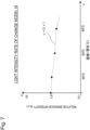
- Fig. 7 illustrates an example of such a model of the rate of change of light intensity.
- the horizontal axis (x axis) is the temperature (°C) of the optical sensor 24
- the vertical axis (y axis) is the relative emission intensity of the optical sensor 24.
- the emission intensity is a relative emission intensity in which the value for a temperature of 0°C is normalized to 1.0.
- I(A) is the measurement value of the actual (uncorrected) light intensity for the wavelength A measured by the optical sensor 24.
- the optical data from the optical sensor 24 is influenced by heat produced by the operations of the light emitter 23. Furthermore, the temperature of the light receiver 22 may also influence the measured optical data. Accordingly, in the present modification, to further improve the measurement accuracy of the measuring device 10, the optical data obtained by the light receiver 22 may be corrected on the basis of not only the temperature of the light emitter 23 but also the temperature of the light receiver 22. In particular, in the case where the light receiver 22 and the light emitter 23 are disposed apart (for example, separated from each other by at least 10 mm), the optical data may be corrected on the basis of both the temperature of the light emitter 23 and the temperature of the light receiver 22.
- a corrected light intensity I c2 ( ⁇ ) corrected on the basis of both the temperature of the light receiver 22 and the temperature of the light emitter 23 is defined as in the following Expression 2.
- I c 2 ⁇ I ⁇ / I ⁇ S t S ⁇ I ⁇ D t D
- the inventor discovered that if the temperature to of the light receiver 22 and the temperature ts of the light emitter 23 are in the temperature range from approximately 15°C to 60°C, the accuracy of the corrected light intensity is maintained through the correction of the optical data. Also, instead of the above 60°C, the upper limit of such a temperature range may be set to an operation-guaranteeing value for the light receiver 22 (a spectroscope, for example) and the light emitter 23 (an LED, for example).
- the timing of measurement is no longer restricted by the temperature condition on the optical sensor 24.
- the measuring device 10 can take measurements at any timings, making the measuring device 10 even easier to use for the user.
- measurements can be taken with stable and consistent accuracy, without being influenced by various temperatures depending on the season or location.
- the method for correcting the optical data for each wavelength of the reflected light in the present modification can be executed in combination with the method for selecting the optical data for which the temperature of the optical sensor 24 substantially corresponds to the designated temperature described above.
- the measuring device 10 for biological tissue according to the first embodiment described above is configured as a standalone measuring device 10.
- the measuring device 10 for biological tissue is provided to an inhalation device 100. That is, the measuring device 10 for biological tissue according to the second embodiment treats oral tissue as the object of measurement that is a portion of biological tissue, and is integrated with the inhalation device 100.
- the measuring device 10 is provided to the inhalation device 100 and used as a portion thereof.
- the inhalation device 100 according to the present embodiment is compact enough to fit in the user's hand, and can be carried and used casually by the user.
- the inhalation device 100 can also be used as a measuring device 10 for oral tissue.
- the inhalation device 100 is a device that generates a substance to be inhaled by the user and may be an electronic tobacco product or a nebulizer, but is not limited thereto.
- the inhalation device 100 may also be a heated flavor inhaler or a non-heated flavor inhaler, and in particular, may include any of various inhalation devices that generate an aerosol or an aerosol with added flavor to be inhaled by the user.
- the generated inhalation component may also contain a gas such as invisible vapor in addition to an aerosol.
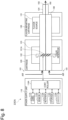
- FIG. 8 is a schematic diagram illustrating a first configuration example of an inhalation device.
- an inhalation device 100A according to the present configuration example includes a power supply unit 110, a cartridge 120, and a flavor-imparting cartridge 130.
- the power supply unit 110 includes a power source 111A, a sensor 112A, a notifier 113A, storage 114A, a communicator 115A, and a controller 116A.
- the cartridge 120 includes a heater 121A, a liquid channel 122, and a liquid reservoir 123.
- the flavor-imparting cartridge 130 includes a flavor source 131 and a mouthpiece 124.
- An air channel 180 is formed in the cartridge 120 and the flavor-imparting cartridge 130.
- the power source 111A, sensor 112A, notifier 113A, storage 114A, communicator 115A, and controller 116A included in the power supply unit 110 substantially includes the configuration of each of the power source 11, sensor 12, notifier 13, storage 14, communicator 15, and controller 16 (data processor 17) included in the measuring device 10 according to the first embodiment.
- controller 16 data processor 17
- the sensor 112A acquires various information pertaining to the inhalation device 100A.
- the sensor 112A may be a pressure sensor such as a microphone condenser, a flow sensor, a temperature sensor, or the like, and acquires a value associated with inhalation by the user.
- the storage 114A stores various information for operations by the inhalation device 100A.
- the storage 114A also stores programs such as firmware in addition to computer-executable instructions for causing the inhalation device 100A to operate.
- the liquid reservoir 123 stores an aerosol source.
- An aerosol is generated by atomizing the aerosol source.
- the aerosol source may be a polyhydric alcohol such as glycerin or propylene glycol and a liquid such as water.
- the aerosol source may also contain tobacco-derived or non-tobacco-derived flavor components.
- the aerosol source may also contain a medicine.
- the aerosol source that is, the liquid stored in the liquid reservoir 123, is channeled from the liquid reservoir 123 and held in the liquid channel 122.
- the liquid channel 122 is a wick formed by twisting fiber materials such as glass fiber or other porous materials such as porous ceramics.
- the aerosol source stored in the liquid reservoir 123 is channeled by the capillary effect of the wick.
- the heater 121A heats the aerosol source to atomize the aerosol source and generate an aerosol.
- the heater 121A is configured as a coil that is wound around the liquid channel 122.
- the heater 121A generates heat, the aerosol source held in the liquid channel 122 is heated and atomized, and an aerosol is generated.
- the heater 121A generates heat when supplied with power from the power source 111A.
- power may be supplied when the sensor 112A detects the user starting inhaling and/or the inputting of prescribed information. Additionally, the supply of power may be stopped when the sensor 112A detects the user finishing inhaling and/or the inputting of prescribed information.
- the flavor source 131 is a component for imparting a flavor component to the aerosol.
- the flavor source 131 may contain tobacco-derived or non-tobacco-derived flavor components.
- the air channel 180 is a channel for air to be inhaled by the user.
- the air channel 180 has a tubular structure with an air inflow hole 181 serving as an inlet for air into the air channel 180 and an air outflow hole 182 serving as an outlet for air from the air channel 180 on either end.
- the liquid channel 122 is disposed on the upstream side (the side close to the air inflow hole 181) and the flavor source 131 is disposed on the downstream side (the side close to the air outflow hole 182).
- Air flowing in from the air inflow hole 181 in association with inhalation by the user is mixed with the aerosol generated by the heater 121A, and as indicated by the arrow 190, passes through the flavor source 131 and is transported to the air outflow hole 182.
- the flavor component contained in the flavor source 131 is imparted to the aerosol.
- the mouthpiece 124 is a member that is put into the user's mouth during inhalation.
- the air outflow hole 182 is disposed in the mouthpiece 124. The user puts the mouthpiece 124 into the user's mouth and inhales, and can thereby draw in the fluid mixture of aerosol and air into the oral cavity.
- configuration example 1 of the inhalation device 100A The above describes configuration example 1 of the inhalation device 100A. Obviously, the configuration of the inhalation device 100A is not limited to the above and may take a variety of configurations exemplified below.
- the inhalation device 100A does not have to include the flavor-imparting cartridge 130.
- the mouthpiece 124 is provided on the cartridge 120.
- the inhalation device 100A may also include multiple types of aerosol sources. By causing multiple types of aerosols generated from the multiple types of aerosol sources to be mixed inside the air channel 180 and inducing a chemical reaction, still other types of aerosols may be generated.
- the means for atomizing the aerosol source is not limited to heating by the heater 121A.
- the means for atomizing the aerosol source may also be vibration atomization or induction heating.
- Fig. 9 is a schematic diagram illustrating a second configuration example of an inhalation device.
- a stick-type substrate 150 is inserted, for example, the stick-type substrate 150 including a flavor-producing substrate such as a filling which is an inhalation component source containing an aerosol source and a flavor source.
- the aerosol source is not limited to a liquid and may also be a solid.
- the inserted stick-type substrate 150 is heated from the outer circumference thereof, and thereby generates a flavor-containing aerosol.
- the inhalation device 100B includes a power source 111B, a sensor 112B, a notifier 113B, storage 114B, a communicator 115B, a controller 116B, a heater 121B, a holder 140, and an insulator 144.
- the power source 111B, the sensor 112B, the notifier 113B, the storage 114B, the communicator 115B, and the controller 116B each function in substantially the same way as the corresponding component included in the inhalation device 100A according to configuration example 1.
- the holder 140 has an internal space 141 and holds the stick-type substrate 150 while accommodating a portion of the stick-type substrate 150 in the internal space 141.
- the holder 140 has an opening 142 that connects the internal space 141 to the outside and holds the stick-type substrate 150 inserted into the internal space 141 from the opening 142.
- the holder 140 is a cylindrical body having the opening 142 and a base part 143 as a base, and demarcates a columnar internal space 141.
- the holder 140 also has a function of demarcating a channel for air to be supplied to the stick-type substrate 150.
- An air inflow hole serving as an inlet for air into the channel is disposed in the base part 143, for example.
- an air outflow hole serving as an outlet for air from the channel is the opening 142.
- the stick-type substrate 150 includes a substrate part 151 and an inhaling part 152.
- the substrate part 151 includes an aerosol source.
- the inhaling part 152 projects out from the opening 142. Additionally, if the user puts the inhaling part 152 projecting out from the opening 142 into the user's mouth and inhales, air flows into the internal space 141 from an air inflow hole not illustrated and arrives inside the user's mouth together with an aerosol produced from the substrate part 151.
- the heater 121B has a configuration similar to the heater 121A according to configuration example 1. However, in the example illustrated in Fig. 9 , the heater 121B is configured in a film form and is disposed to cover the outer circumference of the holder 140. Additionally, when the heater 121B generates heat, the substrate part 151 of the stick-type substrate 150 is heated from the outer circumference, and an aerosol is generated.
- the insulator 144 prevents heat transfer from the heater 121B to other components.
- the insulator 144 is formed from a vacuum insulation material, an aerogel insulation material, or the like.
- the inhalation device 100B is not limited to the above configuration and may take a variety of configurations exemplified below.
- the heater 121B may be configured in a blade form and may be disposed to project into the internal space 141 from the base part 143 of the holder 140.
- the heater 121B in the blade form is inserted into the substrate part 151 of the stick-type substrate 150 and heats the substrate part 151 of the stick-type substrate 150 from the inside.
- the heater 121B may be disposed to cover the base part 143 of the holder 140.
- the heater 121B may also be configured as a combination of two or more of a first heating part that covers the outer circumference of the holder 140, a blade-shaped second heating part, and a third heating part that covers the base part 143 of the holder 140.
- the holder 140 may also include an opening-closing mechanism such as a hinge that opens and closes a portion of a shell that forms the internal space 141. Additionally, by opening and closing the shell, the holder 140 may grip the stick-type substrate 150 inserted into the internal space 141.
- the heater 121B may be provided on the gripping part of the holder 140 and heat the stick-type substrate 150 while pressure is applied.
- the means for atomizing the aerosol source is not limited to heating by the heater 121B.
- the means for atomizing the aerosol source may also be induction heating.
- the inhalation device 100B may further include the heater 121A, the liquid channel 122, the liquid reservoir 123, and the air channel 180 according to configuration example 1, and the air outflow hole 182 of the air channel 180 may double as an air inflow hole into the internal space 141.
- the fluid mixture of air and an aerosol generated by the heater 121A flows into the internal space 141, is further mixed with an aerosol generated by the heater 121B, and arrives inside the user's oral cavity.
- Fig. 10 is a schematic diagram illustrating a schematic exterior of an inhalation device according to the present embodiment.
- the inhalation device 100 is provided with the measuring device 10 for biological tissue.
- the following description takes the inhalation device 100A according to configuration example 1 illustrated in Fig. 8 above as an example, but is not limited thereto and also applies to the inhalation device 100B according to configuration example 2 illustrated in Fig. 9 .
- the power supply unit 110, the cartridge 120, the flavor-imparting cartridge 130, and the mouthpiece illustrated in Fig. 8 are assembled to form the outermost housing of the inhalation device 100A.
- the housing of the inhalation device 100A includes a holding portion 200 and an inhaling portion 210. The user, while holding the holding portion 200 in one hand, puts the inhaling portion 210 into the user's mouth and inhales from the Z-axis direction, and thereby can draw a fluid mixture of aerosol and air into the oral cavity.
- measuring device 10 provided to the inhalation device 100A
- Anticipated examples of measuring device 10 include a proximity type in which the optical sensor 24 and the measurement surface 21 are disposed in close proximity and a separated type in which the optical sensor 24 and the measurement surface 21 are disposed apart.
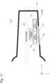
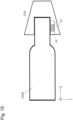
- Fig. 11 is an example of the proximity type and is an enlarged schematic view of the inhaling portion 210.
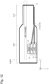
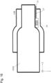
- Fig. 12 is an example of the separated type.
- Figs. 11 and 12 schematically illustrate the positional relationship between the optical sensor 24 (light receiver 22 and light emitter 23) and the measurement surface 21.
- the measurement surface 21 and the heat radiator 26 are provided on the surface of the inhaling portion 210 of the inhalation device 100A, while the optical sensor 24 and the temperature sensor 25 are disposed inside the inhaling portion 210. More specifically, the measurement surface 21 and the heat radiator 26 are provided on a lateral surface 210a of the inhaling portion 210, and the optical sensor 24 including the light receiver 22 and the light emitter 23 is disposed close to the measurement surface 21.
- the light receiver 22 and the light emitter 23 are disposed in parallel with the Z axis in the order of the light emitter 23 and the light receiver 22 in the +Z direction. Also, the elements of the light receiver 22 and the light emitter 23 are pointed in the +Y direction.
- the temperature sensor 25 is disposed close to the optical sensor 24 (particularly the light emitter 23).
- the measurement surface 21 may be provided with a measurement window to be touched by the object of measurement, namely oral tissue.
- the measurement window is highly safe to biological tissue and may be formed using an optically transparent material. For example, acrylic resin, glass, and the like may be used, but the material is not limited thereto.
- the measurement window may be shaped into a film, a plate, or the like. With this arrangement, direct contact between the optical element and biological tissue can be prevented, thereby improving the robustness of the optical sensor 24 and also improving user feel.
- the area of the measurement window (that is, the area of the measurement surface 21 put into contact with the object of measurement) may be 300 mm 2 or less, for example.
- the measurement surface 21 is provided on the inhaling portion 210 and therefore the object of measurement may be oral tissue, but is not necessarily limited thereto. In other words, besides oral tissue such as the tongue and lower lip, the object of measurement may be applied broadly to body surface skin and the like.
- the heat radiator 26 is disposed beside the measurement surface 21 on the lateral surface 210a.
- the heat radiator 26 may be disposed adjacent to the light emitter 23 to release heat produced by the optical sensor 24, particularly the light emitter 23, to the outside of the inhaling portion 210.
- the heat radiator 26 may be a heat-conducting plate, and may also be configured as a portion of the measurement surface 21. With this arrangement, released heat can be conducted to the object of measurement, namely oral tissue, to promote saliva secretion.
- the lateral surface 210a of the inhaling portion 210 may form an inclined surface (or a tapered surface) inclined by an angle ⁇ toward the light receiver 22 with respect to the Z direction.
- the inhaling portion 210 has a shape that is tapered in the +Z direction.
- the angle ⁇ may be adjusted in the range from 0° to 15°. More preferably, the angle ⁇ may be adjusted in the range from 1° to 5° (for example, 2°).
- the measurement surface 21 may be disposed on the lateral surface 210a of the inhaling portion 210, at a position between the light receiver 22 and the light emitter 23 from the tip of the inhaling portion 210.
- the light receiver 22 can be configured to receive light that is radiated from the light emitter 23 and reflected from the object of measurement through the measurement surface 21.
- the distance between the light receiver 22 and the light emitter 23 may be set from 3 mm to 20 mm. More preferably, the distance may be adjusted in the range from 5 mm to 15 mm.
- the distance between the light emitter 23 and the measurement surface 21 may also be set to 20 mm, more preferably adjusted to be less than or equal to 10 mm.
- the temperature sensor 25 may be disposed near the light emitter 23, at a position between the optical sensor 24 and the air channel (dashed-line arrow) provided in the inhalation device 100A.
- the heat of the aerosol is also thought to induce variation in the temperature of the optical sensor 24. Accordingly, a distance between the optical sensor 24 and the air channel may be secured, and the temperature sensor 25 may also be disposed in between.
- the senor 12 including the optical sensor 24 and the temperature sensor 25 is disposed inside the inhaling portion 210 of the inhalation device 100A. Otherwise, other elements such as the controller 16 (not illustrated) are disposed inside the holding portion 200 of the inhalation device 100A. The sensor 12 and the controller 16 are electrically connected by a wire inside the inhalation device 100A.
- the measurement surface 21 and the optical sensor 24 are disposed in close proximity, while the heat radiator 26 and the temperature sensor 25 are also disposed in close proximity inside the inhaling portion 210.
- the influence of heat produced by the optical sensor 24 can be avoided, and the measuring device 10 can be provided even to a compact device like the inhalation device 100A.
- the optical sensor 24 and the temperature sensor 25 are disposed inside the holding portion 200 of the inhalation device 100A (note that the heat radiator 26 is not illustrated).
- the measurement surface 21 is provided in the inhaling portion 210 of the inhalation device 100A.
- the light receiver 22 and the light emitter 23 are joined to the measurement surface 21 through two optical fibers 27 (27A, 27B), respectively.
- the optical fibers 27 by applying the optical fibers 27, the light receiver 22 and the light emitter 23 inside the holding portion 200 can be separated from the measurement surface 21 inside the inhaling portion 210.
- the separated-type arrangement example is advantageous in that by applying the optical fibers 27, the measurement surface 21 provided on the inhaling portion 210 side can be narrowed.
- the optical fibers 27 may be, but are not limited to, quartz fibers. Quartz fibers are known to be implemented with a diameter approximately from 200 ⁇ m to 600 ⁇ m.
- Figs. 13 and 14 will be additionally referenced to describe the positional relationship between the optical sensor 24 (light receiver 22 and light emitter 23) and the measurement surface 21 in further detail.
- Fig. 13 is a plan view schematically illustrating the inhaling portion 210 of the inhalation device 100A illustrated in Fig. 12 from the Z-axis direction
- Fig. 14 is a plan view schematically illustrating the Y-Z plane of the inhalation device 100A.
- two optical fibers 27A and 27B are used. Furthermore, as illustrated in Fig. 13 , the end faces of the two optical fibers 27A and 27B form the measurement surface 21.
- the distance between the end faces of the optical fibers 27A and 27B may be set from 0 ⁇ m to 20 mm. In particular, in the case of measuring a substance on the surface of biological tissue such as an oral surface, the distance between the end faces of the optical fibers 27A and 27B may be adjusted in the range from 0 ⁇ m to 3 mm. Note that if the distance between the end faces of the optical fibers 27A and 27B is 0, the end faces of the optical fibers 27A and 27B make contact each other in some cases. In this way, by bring the end faces of the optical fibers 27A and 27B in proximity or contact with each other as the measurement surface 21, the accuracy of the measurement result can be improved.
- the two optical fibers 27A and 27B may be disposed to face each other at a predetermined angle with respect to the Z-axis direction. That is, the two optical fibers 27A and 27B may be disposed such that the distance in between decreases proceeding from the optical sensor 24 (light receiver 22 and light emitter 23) toward the end faces of the optical fibers 27A and 27B.
- the predetermined angle may be set to 10° or less, for example.
- the end faces of the fibers are normally at 90° with respect to the axial direction of the fibers, but the end faces may also be inclined from 80° to 90° such that the inclined surfaces face each other. With this arrangement, the light receiver 22 can receive reflected light more effectively.
- the measurement surface 21 side of the optical fiber 27 has one end face while the opposite side is split two ways and joined to the light receiver 22 and the light emitter 23, respectively.
- the temperature sensor 25 may be disposed near the light emitter 23, at a position between the optical sensor 24 and the air channel (dashed-line arrow) provided in the inhalation device 100A.
- the heat of the aerosol is also thought to induce variation in the temperature of the optical sensor 24. Accordingly, a distance between the optical sensor 24 and the air channel may be secured, and the temperature sensor 25 may be disposed in between.
- the light receiver 22 and the light emitter 23 inside the holding portion 200 are separated from the measurement surface 21 inside the inhaling portion 210 through the optical fibers 27.
- the inhaling portion 210 in particular can be made more compact, and the measuring device 10 can be provided even to a compact device like the inhalation device 100A.
- An example of operations by the inhalation device is as described in the first embodiment.
- data while the user is using the inhalation device may be applied to measuring operations.
- the controller 16 may be controlled to execute the measuring operations (steps S40 to S60 in Fig. 4 ) only if the intensity of light (particularly, the quantity of light) received by the light receiver 22 is equal to or greater than a prescribed threshold value, for example.
- various information (such as a puff count, a puff operation duration, and a number of consumed capsules, for example) pertaining to inhaling operations by the user may be utilized as or associated with a measurement result for the inhalation device.
- the measuring device 10 for biological tissue is configured as a standalone measuring device 10. Also, in the second embodiment, the measuring device 10 for biological tissue is provided to the inhalation device 100 and integrated with the inhalation device 100. In contrast, in the third embodiment, the measuring device 10 for biological tissue is configured to be removably attached to the inhalation device 100.
- the following description takes the inhalation device 100A according to configuration example 1 illustrated in Fig. 8 above as an example, but is not limited thereto.
- a mechanism may be provided such that the measuring device 10, which may also operate in a standalone manner, can be mechanically attached to the inhalation device 100A.
- the measuring device 10 which may also operate in a standalone manner, can be mechanically attached to the inhalation device 100A.
- a measurement may also be taken by the measuring device 10.
- the measuring device 10 may be electrically connected to the inhalation device 100A in accordance with the measuring device 10 being attached to the inhalation device 100A.
- power may be fed from the power source 111A of the inhalation device 100 to the measuring device 10 to activate the sensor 12 and the controller 16.
- various programs and/or settings information stored in the storage 114A of the inhalation device 100A may be configured to be usable by the measuring device 10.
- a notification of a measurement result may be issued by the notifier 113A of the inhalation device 100A.
- the measuring device 10 for biological tissue is provided with at least the sensor 12 and the measurer 20.
- Figs. 15 and 16 are diagrams schematically illustrating a state in which such a measuring device 10 is attached to the inhalation device 100A.
- a measuring device 10A in Fig. 15 is an example of a cap-type device that is attachable to the tip of the inhaling portion 210 of the inhalation device 100A.
- the cap-type measuring device 10A may be configured as an inhalation device 10A of the proximity type described in the second embodiment, for example.
- the measurement surface 21 is included on a tapered surface, and the optical sensor 24 is disposed close to the measurement surface.
- the optical sensor 24 may also be provided on an inner wall of the measuring device 10A. Note that the positional relationship between the measurement surface 21 and the optical sensor 24 is as described in the second embodiment. (The temperature sensor 25 and the heat radiator 26 are omitted from illustrated here.)
- a measuring device 10B in Fig. 16 is an example of a case-type device that is attachable by being penetrated by the tip of the inhaling portion 210 of the inhalation device 100A.
- the case-type measuring device 10B may be configured as an inhalation device 10A of the separated type described in the second embodiment, for example.
- the optical sensor 24 and the optical fibers 27 may be provided on an inner wall of the measuring device 10B. Additionally, as illustrated in the diagram, the optical fibers 27 running from the optical sensor 24 may be positioned to form the measurement surface 21 adjoining the inhaling portion 210 of the inhalation device 100A when the measuring device 10B is attached. (Like Fig. 15 , the temperature sensor 25 and the heat radiator 26 are omitted from illustrated here.)
- the measuring devices 10A and 10B for biological tissue can be freely and removably attached to the inhalation device 100A.
- the inhalation device 100A may also be operable while the measuring device 10A or 10B is attached to the inhalation device 100A. In this way, the measuring devices 10A and 10B are sufficiently compact devices, and the user can casually use the measuring device 10 together with the inhalation device 100A.
- a measuring device an inhalation device, and a method according to several embodiments are described with reference to the drawings. It is understood that the present disclosure may also be carried out as a program that, when executed by a processor, causes the processor to execute a method causing the measuring device or the inhalation device to operate, or may be carried out as a computer-readable storage medium storing the program.
Landscapes
- Health & Medical Sciences (AREA)
- Life Sciences & Earth Sciences (AREA)
- Physics & Mathematics (AREA)
- Pathology (AREA)
- General Health & Medical Sciences (AREA)
- Engineering & Computer Science (AREA)
- Veterinary Medicine (AREA)
- Biomedical Technology (AREA)
- Heart & Thoracic Surgery (AREA)
- Medical Informatics (AREA)
- Molecular Biology (AREA)
- Surgery (AREA)
- Animal Behavior & Ethology (AREA)
- Biophysics (AREA)
- Public Health (AREA)
- Dentistry (AREA)
- Oral & Maxillofacial Surgery (AREA)
- Optics & Photonics (AREA)
- Biochemistry (AREA)
- Immunology (AREA)
- General Physics & Mathematics (AREA)
- Chemical & Material Sciences (AREA)
- Analytical Chemistry (AREA)
- Rheumatology (AREA)
- Orthopedic Medicine & Surgery (AREA)
- Physical Education & Sports Medicine (AREA)
- Spectroscopy & Molecular Physics (AREA)
- Audiology, Speech & Language Pathology (AREA)
- Dermatology (AREA)
- Multimedia (AREA)
- Measuring And Recording Apparatus For Diagnosis (AREA)
- Investigating Or Analysing Materials By Optical Means (AREA)
Applications Claiming Priority (1)
| Application Number | Priority Date | Filing Date | Title |
|---|---|---|---|
| PCT/JP2020/041022 WO2022091403A1 (fr) | 2020-11-02 | 2020-11-02 | Dispositif de mesure pour tissu vivant, dispositif d'aspiration, procédé de mesure pour tissu vivant, et programme |
Publications (1)
| Publication Number | Publication Date |
|---|---|
| EP4238487A1 true EP4238487A1 (fr) | 2023-09-06 |
Family
ID=81382182
Family Applications (1)
| Application Number | Title | Priority Date | Filing Date |
|---|---|---|---|
| EP20959918.2A Pending EP4238487A1 (fr) | 2020-11-02 | 2020-11-02 | Dispositif de mesure pour tissu vivant, dispositif d'aspiration, procédé de mesure pour tissu vivant, et programme |
Country Status (5)
| Country | Link |
|---|---|
| US (1) | US20230086075A1 (fr) |
| EP (1) | EP4238487A1 (fr) |
| JP (1) | JP7453407B2 (fr) |
| KR (1) | KR20230002917A (fr) |
| WO (1) | WO2022091403A1 (fr) |
Family Cites Families (23)
| Publication number | Priority date | Publication date | Assignee | Title |
|---|---|---|---|---|
| JPH058974Y2 (fr) * | 1989-12-28 | 1993-03-05 | ||
| JP4596850B2 (ja) | 2003-08-08 | 2010-12-15 | シチズン電子株式会社 | 両面発光照明ユニット |
| GB2406283B (en) * | 2003-09-24 | 2006-04-05 | Altana Pharma Ag | Compliance monitor and method |
| EP1616524A4 (fr) | 2004-03-29 | 2009-07-08 | Panasonic Corp | Element optique pour mesurer des informations biologiques et instrument de mesure d'informations biologiques utilisant ledit element |
| JP2006047209A (ja) * | 2004-08-06 | 2006-02-16 | Kubota Corp | 分光分析装置 |
| JP4216272B2 (ja) * | 2004-08-20 | 2009-01-28 | パナソニック株式会社 | 生体情報測定用光学部材、および生体情報算出装置 |
| JP2007059537A (ja) * | 2005-08-23 | 2007-03-08 | Sumitomo Electric Ind Ltd | 光送信器 |
| JP4540650B2 (ja) | 2005-09-20 | 2010-09-08 | 三洋電機株式会社 | 撮影装置 |
| JP2007143702A (ja) * | 2005-11-25 | 2007-06-14 | Matsushita Electric Works Ltd | 体内成分計測装置及び体内成分計測方法 |
| EP2000801B1 (fr) | 2006-03-28 | 2016-12-07 | Terumo Kabushiki Kaisha | Dispositif et procédé de mesure des composants d'un fluide corporel |
| JP4470939B2 (ja) | 2006-12-25 | 2010-06-02 | パナソニック電工株式会社 | 生体スペクトル測定装置 |
| US9259176B2 (en) * | 2010-11-16 | 2016-02-16 | Hitachi Medical Corporation | Biological optical measurement instrument and operation method therefor |
| WO2016199062A1 (fr) | 2015-06-12 | 2016-12-15 | Philip Morris Products S.A. | Contrôle biologique pour articles à fumer électroniques |
| WO2016199065A1 (fr) | 2015-06-12 | 2016-12-15 | Philip Morris Products S.A. | Détection d'articles de génération d'aérosol |
| CN108369183B (zh) * | 2015-12-09 | 2022-08-19 | 迪亚蒙泰克股份有限公司 | 用于分析材料的装置和方法 |
| CA3036631A1 (fr) * | 2016-12-09 | 2018-06-14 | Trudell Medical International | Nebuliseur intelligent |
| CN109007975B (zh) * | 2017-06-12 | 2022-12-06 | 常州市派腾电子技术服务有限公司 | 电子烟控制方法以及电子烟 |
| CN107319639A (zh) * | 2017-07-20 | 2017-11-07 | 李广辉 | 一种具有检测血氧饱和度的电子烟 |
| WO2019162935A1 (fr) * | 2018-02-24 | 2019-08-29 | Clearskin Ltd | Compositions, dispositifs, systèmes, kits et méthodes de traitement d'une affection cutanée |
| EP3764828A4 (fr) | 2018-03-14 | 2022-02-23 | Canopy Growth Corporation | Dispositifs de vapotage, comprenant des cartouches, des comprimés, des capteurs et des commandes pour des dispositifs de vapotage, et leurs procédés de fabrication et d'utilisation |
| JP2019173923A (ja) | 2018-03-29 | 2019-10-10 | アイシン・エィ・ダブリュ株式会社 | 車両用駆動装置 |
| JP6774478B2 (ja) * | 2018-11-02 | 2020-10-21 | 日本たばこ産業株式会社 | 個人用健康状態評価システム |
| US11150332B1 (en) * | 2020-06-30 | 2021-10-19 | Apple Inc. | Self-calibrating optical transceiver system with reduced crosstalk sensitivity for through-display proximity sensing |
-
2020
- 2020-11-02 JP JP2022558800A patent/JP7453407B2/ja active Active
- 2020-11-02 WO PCT/JP2020/041022 patent/WO2022091403A1/fr active Application Filing
- 2020-11-02 EP EP20959918.2A patent/EP4238487A1/fr active Pending
- 2020-11-02 KR KR1020227040624A patent/KR20230002917A/ko unknown
-
2022
- 2022-11-29 US US18/071,374 patent/US20230086075A1/en active Pending
Also Published As
| Publication number | Publication date |
|---|---|
| JP7453407B2 (ja) | 2024-03-19 |
| JPWO2022091403A1 (fr) | 2022-05-05 |
| US20230086075A1 (en) | 2023-03-23 |
| KR20230002917A (ko) | 2023-01-05 |
| WO2022091403A1 (fr) | 2022-05-05 |
Similar Documents
| Publication | Publication Date | Title |
|---|---|---|
| US11992044B2 (en) | Vaporization device systems and methods | |
| US9549573B2 (en) | Vaporization device systems and methods | |
| ES2744774T3 (es) | Detección en artículos generadores de aerosol | |
| US20150351456A1 (en) | Electronic cigarette | |
| EP3236789B1 (fr) | Dispositif électronique à fumer à fonction de mesure d'aérosol | |
| TWI828016B (zh) | 用於產生可吸入蒸汽之電子裝置及包括該電子裝置之系統及套件 | |
| KR20200133212A (ko) | 바이오센서를 갖는 에어로졸 발생 시스템 | |
| JP2021500040A (ja) | エアロゾル生成装置 | |
| JP2021510504A (ja) | 複数のセンサーを備えるエアロゾル発生装置 | |
| JP2020195298A (ja) | エアロゾル吸引器、エアロゾル吸引器用の制御装置、エアロゾル吸引器の制御方法及びプログラム | |
| ES2920054T3 (es) | Conjunto de calentamiento por inducción para un dispositivo generador de vapor | |
| JP7291785B2 (ja) | エアロゾル生成装置及びその動作方法 | |
| JP6991200B2 (ja) | エアロゾル-解析のための分光計を有するエアロゾル発生システム | |
| WO2020208868A1 (fr) | Dispositif de commande pour inhalateur d'aérosol, procédé de commande pour inhalateur d'aérosol, programme et inhalateur d'aérosol | |
| US20230000172A1 (en) | Inhaling device | |
| JP6928658B2 (ja) | 流体センサーを備えたエアロゾル発生システム | |
| EP4238487A1 (fr) | Dispositif de mesure pour tissu vivant, dispositif d'aspiration, procédé de mesure pour tissu vivant, et programme | |
| JP2023508196A (ja) | エアロゾル生成装置及びそれを制御する方法 | |
| US20230319953A1 (en) | Vaporizer apparatus | |
| WO2020208870A1 (fr) | Dispositif de commande pour un inhalateur d'aérosol, procédé de commande pour un inhalateur d'aérosol, programme et inhalateur d'aérosol | |
| EP3791740A1 (fr) | Dispositif/système de substitution du tabac | |
| EP4108109A1 (fr) | Dispositif d'inhalation, procédé de commande et programme | |
| JP7494171B2 (ja) | 装置エアロゾル発生システム用センサー | |
| WO2023089752A1 (fr) | Dispositif d'inhalation | |
| RU2795133C2 (ru) | Электронное устройство для вейпинга |
Legal Events
| Date | Code | Title | Description |
|---|---|---|---|
| STAA | Information on the status of an ep patent application or granted ep patent |
Free format text: STATUS: THE INTERNATIONAL PUBLICATION HAS BEEN MADE |
|
| PUAI | Public reference made under article 153(3) epc to a published international application that has entered the european phase |
Free format text: ORIGINAL CODE: 0009012 |
|
| STAA | Information on the status of an ep patent application or granted ep patent |
Free format text: STATUS: REQUEST FOR EXAMINATION WAS MADE |
|
| 17P | Request for examination filed |
Effective date: 20221130 |
|
| AK | Designated contracting states |
Kind code of ref document: A1 Designated state(s): AL AT BE BG CH CY CZ DE DK EE ES FI FR GB GR HR HU IE IS IT LI LT LU LV MC MK MT NL NO PL PT RO RS SE SI SK SM TR |
|
| DAV | Request for validation of the european patent (deleted) | ||
| DAX | Request for extension of the european patent (deleted) |