EP4237705B1 - Anordnung mit einem getriebe und einer arbeitsmaschine, verfahren zur simulation - Google Patents
Anordnung mit einem getriebe und einer arbeitsmaschine, verfahren zur simulation Download PDFInfo
- Publication number
- EP4237705B1 EP4237705B1 EP21799266.8A EP21799266A EP4237705B1 EP 4237705 B1 EP4237705 B1 EP 4237705B1 EP 21799266 A EP21799266 A EP 21799266A EP 4237705 B1 EP4237705 B1 EP 4237705B1
- Authority
- EP
- European Patent Office
- Prior art keywords
- drive shaft
- output shaft
- shn
- shaft
- shb
- Prior art date
- Legal status (The legal status is an assumption and is not a legal conclusion. Google has not performed a legal analysis and makes no representation as to the accuracy of the status listed.)
- Active
Links
Images

Classifications
-
- F—MECHANICAL ENGINEERING; LIGHTING; HEATING; WEAPONS; BLASTING
- F16—ENGINEERING ELEMENTS AND UNITS; GENERAL MEASURES FOR PRODUCING AND MAINTAINING EFFECTIVE FUNCTIONING OF MACHINES OR INSTALLATIONS; THERMAL INSULATION IN GENERAL
- F16H—GEARING
- F16H57/00—General details of gearing
- F16H57/02—Gearboxes; Mounting gearing therein
- F16H57/025—Support of gearboxes, e.g. torque arms, or attachment to other devices
-
- F—MECHANICAL ENGINEERING; LIGHTING; HEATING; WEAPONS; BLASTING
- F16—ENGINEERING ELEMENTS AND UNITS; GENERAL MEASURES FOR PRODUCING AND MAINTAINING EFFECTIVE FUNCTIONING OF MACHINES OR INSTALLATIONS; THERMAL INSULATION IN GENERAL
- F16D—COUPLINGS FOR TRANSMITTING ROTATION; CLUTCHES; BRAKES
- F16D1/00—Couplings for rigidly connecting two coaxial shafts or other movable machine elements
- F16D1/02—Couplings for rigidly connecting two coaxial shafts or other movable machine elements for connecting two abutting shafts or the like
- F16D1/033—Couplings for rigidly connecting two coaxial shafts or other movable machine elements for connecting two abutting shafts or the like by clamping together two faces perpendicular to the axis of rotation, e.g. with bolted flanges
-
- F—MECHANICAL ENGINEERING; LIGHTING; HEATING; WEAPONS; BLASTING
- F16—ENGINEERING ELEMENTS AND UNITS; GENERAL MEASURES FOR PRODUCING AND MAINTAINING EFFECTIVE FUNCTIONING OF MACHINES OR INSTALLATIONS; THERMAL INSULATION IN GENERAL
- F16D—COUPLINGS FOR TRANSMITTING ROTATION; CLUTCHES; BRAKES
- F16D1/00—Couplings for rigidly connecting two coaxial shafts or other movable machine elements
- F16D1/10—Quick-acting couplings in which the parts are connected by simply bringing them together axially
- F16D1/108—Quick-acting couplings in which the parts are connected by simply bringing them together axially having retaining means rotating with the coupling and acting by interengaging parts, i.e. positive coupling
-
- F—MECHANICAL ENGINEERING; LIGHTING; HEATING; WEAPONS; BLASTING
- F16—ENGINEERING ELEMENTS AND UNITS; GENERAL MEASURES FOR PRODUCING AND MAINTAINING EFFECTIVE FUNCTIONING OF MACHINES OR INSTALLATIONS; THERMAL INSULATION IN GENERAL
- F16D—COUPLINGS FOR TRANSMITTING ROTATION; CLUTCHES; BRAKES
- F16D3/00—Yielding couplings, i.e. with means permitting movement between the connected parts during the drive
- F16D3/02—Yielding couplings, i.e. with means permitting movement between the connected parts during the drive adapted to specific functions
- F16D3/06—Yielding couplings, i.e. with means permitting movement between the connected parts during the drive adapted to specific functions specially adapted to allow axial displacement
-
- F—MECHANICAL ENGINEERING; LIGHTING; HEATING; WEAPONS; BLASTING
- F16—ENGINEERING ELEMENTS AND UNITS; GENERAL MEASURES FOR PRODUCING AND MAINTAINING EFFECTIVE FUNCTIONING OF MACHINES OR INSTALLATIONS; THERMAL INSULATION IN GENERAL
- F16H—GEARING
- F16H57/00—General details of gearing
- F16H57/0018—Shaft assemblies for gearings
-
- F—MECHANICAL ENGINEERING; LIGHTING; HEATING; WEAPONS; BLASTING
- F16—ENGINEERING ELEMENTS AND UNITS; GENERAL MEASURES FOR PRODUCING AND MAINTAINING EFFECTIVE FUNCTIONING OF MACHINES OR INSTALLATIONS; THERMAL INSULATION IN GENERAL
- F16H—GEARING
- F16H57/00—General details of gearing
- F16H57/0018—Shaft assemblies for gearings
- F16H57/0037—Special features of coaxial shafts, e.g. relative support thereof
-
- F—MECHANICAL ENGINEERING; LIGHTING; HEATING; WEAPONS; BLASTING
- F16—ENGINEERING ELEMENTS AND UNITS; GENERAL MEASURES FOR PRODUCING AND MAINTAINING EFFECTIVE FUNCTIONING OF MACHINES OR INSTALLATIONS; THERMAL INSULATION IN GENERAL
- F16H—GEARING
- F16H57/00—General details of gearing
- F16H57/02—Gearboxes; Mounting gearing therein
- F16H57/023—Mounting or installation of gears or shafts in the gearboxes, e.g. methods or means for assembly
-
- G—PHYSICS
- G06—COMPUTING OR CALCULATING; COUNTING
- G06F—ELECTRIC DIGITAL DATA PROCESSING
- G06F30/00—Computer-aided design [CAD]
- G06F30/10—Geometric CAD
- G06F30/17—Mechanical parametric or variational design
-
- F—MECHANICAL ENGINEERING; LIGHTING; HEATING; WEAPONS; BLASTING
- F16—ENGINEERING ELEMENTS AND UNITS; GENERAL MEASURES FOR PRODUCING AND MAINTAINING EFFECTIVE FUNCTIONING OF MACHINES OR INSTALLATIONS; THERMAL INSULATION IN GENERAL
- F16D—COUPLINGS FOR TRANSMITTING ROTATION; CLUTCHES; BRAKES
- F16D1/00—Couplings for rigidly connecting two coaxial shafts or other movable machine elements
- F16D1/10—Quick-acting couplings in which the parts are connected by simply bringing them together axially
- F16D2001/103—Quick-acting couplings in which the parts are connected by simply bringing them together axially the torque is transmitted via splined connections
-
- F—MECHANICAL ENGINEERING; LIGHTING; HEATING; WEAPONS; BLASTING
- F16—ENGINEERING ELEMENTS AND UNITS; GENERAL MEASURES FOR PRODUCING AND MAINTAINING EFFECTIVE FUNCTIONING OF MACHINES OR INSTALLATIONS; THERMAL INSULATION IN GENERAL
- F16H—GEARING
- F16H57/00—General details of gearing
- F16H57/02—Gearboxes; Mounting gearing therein
- F16H2057/02039—Gearboxes for particular applications
- F16H2057/02043—Gearboxes for particular applications for vehicle transmissions
Definitions
- the invention relates to an arrangement comprising a drive-side transmission with an output shaft of the transmission which extends along an axis, and comprising a working machine with a drive shaft which is torsionally rigidly connected to the output shaft.
- the invention also includes a computer-implemented method for simulating an arrangement and a corresponding computer program product for carrying out this method by means of at least one computer.
- a drive shaft of a motor designed as a hollow shaft is known, which is rotationally fixedly coupled radially on the inside via an internal toothing to a radially outside short toothing of an output shaft of a transmission supported by a torque arm.
- a gearbox for an extruder in which a drive power is transmitted via spur gear stages to a planetary gear supported by a torque arm, whose two-part output shaft protrudes on different sides of the gearbox in order to drive the respective extruder screws.
- the two-part output shaft connected to a planet carrier of the planetary gear has two hollow shafts connected to one another in a rotationally fixed manner via a short gearing, with which the associated extruder screw can be fastened via a gear or a flange screw connection.
- a gearbox for a wind turbine in which a drive power is transmitted to a generator via a spur gear stage from a planetary gear supported by a torque arm, whereby the spur gear stage is coupled in a rotationally fixed manner to a sun shaft designed as a hollow shaft via a short gearing.
- the spur gear stage has an output shaft protruding from the gearbox housing, which is designed as a solid shaft.
- a gearbox for a wind turbine in which a drive power is introduced via a planet carrier of a planetary gear supported by a torque arm and is output to a generator via a sun shaft, whereby the sun shaft is designed as a solid shaft.
- the invention is based on the object of creating a reliable arrangement of the type defined at the outset, which can withstand the high loads incurred while requiring moderate space.
- the invention proposes an arrangement of the type defined at the outset, in which the transmission on the working machine is supported by means of the connection of the output shaft to the drive shaft and by means of a torque support for at least 90% of the forces generated during operation, wherein the connection of the output shaft to the drive shaft is designed to be rigid in order to support transverse forces, wherein the axial end of the drive shaft is designed as a hollow shaft, wherein the axial end of the output shaft has a stump which is at least partially arranged in the hollow shaft of the drive shaft.
- the drive shaft has a shape in the area of the hollow shaft design, with a holding element being attached to the axial end of the output shaft, which is designed as a stump, by means of Fastening means in such a way that the formation is clamped in the area between the holding element and an axial contact surface of the other output shaft.
- the holding element is preferably made of metal.
- the flange can be attached to the output shaft by means of the holding element and then the flange can be fastened to the drive shaft.
- the holding element which can particularly advantageously be ring-shaped, i.e. designed as a retaining ring, can be designed in one piece, which is particularly expedient for simplicity of assembly and for strength and smooth running.
- the arrangement according to the invention particularly preferably enables free axial accessibility to the mounting position of the holding element, in particular without an axially extending continuation of a shaft requiring a divisible - at least 2-part - design of the holding element.
- the arrangement according to the invention preferably comprises a planetary gear as a transmission and is preferably part of a roller press or a mill, e.g. a sugar mill, preferably with individual drive or various other applications in the industrial sector.
- the arrangement according to the invention can be described as "shaft-riding" with regard to the transmission.
- the torque on the transmission or transmission housing is diverted by means of a torque arm, e.g. indirectly or directly introduced into a foundation.
- the torque can also be diverted by means of adjacent machine elements, e.g. via the working machine to which the torque arm is attached.
- the torque arm is attached to the transmission in such a way that the transmission is prevented from axial rotation (with respect to the output shaft). Other degrees of freedom of movement are preferably not restricted by the torque arm.
- the drive shaft of the working machine is in particular rigidly coupled to the output shaft of the transmission, so that preferably a radial offset and/or tiltability between the drive shaft of the working machine and the output shaft of the transmission is eliminated.
- the axes of rotation of the drive shaft of the working machine and the output shaft of the transmission are coaxially aligned with each other, so that the axes of rotation of the drive shaft of the working machine and the output shaft of the transmission can coincide.
- an axial relative movement of the drive shaft of the working machine relative to the output shaft of the transmission is also blocked.
- the drive shaft of the working machine and the output shaft of the transmission can be centered relative to each other.
- Torques occurring in the arrangement can thus be supported almost completely, in particular at least 90%, via the torque support.
- a torque to be supported that is introduced into the transmission by the working machine via the drive shaft is therefore not transmitted to the connection point of the drive shaft of the working machine. with the output shaft of the gearbox, but is diverted via the output shaft of the gearbox and only supported via the torque arm at a distance from the drive shaft of the work machine.
- the torque to be supported introduced by the work machine can thus be passed on via the individual gearings of the gearbox until it can be supported via the torque arm.
- the gearbox is designed in particular as at least a single-stage, preferably multi-stage, planetary gear, of which a toothed gear component, for example a fixed ring gear, is firmly connected to a gearbox housing, to which the torque arm can in turn be connected.
- the torque to be supported introduced by the work machine is thus guided and supported via the individual gearings of the gearbox to the gearbox housing and the torque arm, so that good stability and a low installation space requirement are achieved.
- the drive shaft of the working machine is designed as a hollow shaft in particular essentially only in an axial region in which the drive shaft surrounds the output shaft of the transmission radially on the outside, and is otherwise designed as a solid shaft.
- the region of the drive shaft forming the hollow shaft is designed, for example, as a cylindrical recess which is introduced on an axial end face, for example by turning, coaxially to the axis of rotation of the drive shaft.
- the output shaft of the transmission is preferably designed as a solid shaft. A continuous cylindrical opening in the axial direction running coaxially to the axis of rotation can be avoided in the output shaft, so that the output shaft can transmit the loads that occur without significant deflection even if the nominal diameter is smaller than the drive shaft of the working machine.
- the output shaft is in particular the last shaft in the direction of torque that can still be attributed to the transmission, which in particular protrudes from a transmission housing of the transmission or with the shaft protruding into the transmission housing of the transmission.
- Drive shaft is connected.
- the output shaft can represent a power output of the transmission.
- the drive shaft is in particular the first shaft in the torque direction that can still be attributed to the working machine, which in particular protrudes from a housing of the working machine or is connected to the output shaft that protrudes into the housing of the working machine.
- the output shaft can represent a power input of the working machine.
- the rigid connection between the drive shaft of the working machine and the output shaft of the gearbox means that deflection across the axis of rotation can be avoided. Instead, the transverse forces that occur can be transferred to the torque support via the gearbox and supported spatially offset from the connection point between the drive shaft of the working machine and the output shaft of the gearbox. This makes it possible to save on additional support in the area of the connection point between the drive shaft of the working machine and the output shaft of the gearbox.
- the drive shaft is supported on the output shaft via a radial support to transfer transverse forces.
- the radial support is formed, for example, by a step or a shoulder on which the drive shaft can preferably lie flat on the output shaft.
- the radial support is in particular part of a centering of the drive shaft on the output shaft.
- the radial support acting transversely to the axis of rotation of the drive shaft of the working machine and/or the output shaft of the transmission i.e. in particular essentially in the radial direction, can therefore be provided between the drive shaft of the working machine and/or the output shaft of the transmission, via which transverse forces occurring in the radial direction can be supported and diverted to the rotary support via the transmission.
- the drive shaft is supported on the output shaft via an axial support to absorb longitudinal forces.
- the axial support is, for example, provided by a A step or a shoulder is formed on which the drive shaft can preferably lie flat against the output shaft.
- the axial support is in particular part of a centering of the drive shaft on the output shaft.
- the axial support acting longitudinally to the axis of rotation of the drive shaft of the working machine and/or the output shaft of the gearbox i.e. in particular essentially in the axial direction, can be provided between the drive shaft of the working machine and/or the output shaft of the gearbox, via which longitudinal forces occurring in the axial direction can be supported and diverted to the rotary support via the gearbox.
- the arrangement is designed such that the transmission on the working machine is completely supported against the forces arising during operation by means of the connection of the output shaft to the drive shaft and by means of the torque support.
- a characteristic of this arrangement is that the element connecting the working machine shaft and the transmission shaft must transmit not only the drive torque but also the weight loads of the transmission and other components (engine, clutch, etc.). This results in high alternating bending loads at the connection.
- the short toothing critical for dimensioning on the maximum possible diameter of the output shaft or the stub.
- the outer diameter of the output shaft short toothing is between 85 - 100% of the outer diameter of the area of the output shaft that borders the stub.
- the term "stub" refers only to an end section of the shaft, which in particular does not have to have a different diameter than the rest of the shaft or be designed differently in any other way. Since this connection not only the drive torque but also transverse forces are transmitted.
- the drive shaft is constructed in a modular manner, such that the axial end of the drive shaft is designed as a first axial section as a flange, which is axially attached to a second axial section of the drive shaft, wherein the flange forms the end axial shaft section, which is designed as a hollow shaft.
- this modular construction enables the use of the arrangement according to the invention with adjacent standard components.
- a flange can be used to connect the transmission and working machine shaft.
- the flange is preferably screwed to the drive shaft or working machine shaft.
- the flange can be designed as a cast component, particularly made of metal, in a particularly cost-effective and practical way.
- a conventional arrangement of the type defined at the beginning it is only possible to manufacture the flange from a high-strength material under the correspondingly high loads.
- the invention also opens up the possibility of designing it as a cast component.
- a forged part is significantly more expensive than a comparable cast variant.
- At least one first radial drive shaft centering can be provided at an axial end of the drive shaft, wherein at least one radial output shaft centering is provided at an axial end of the output shaft to which the drive shaft is connected, wherein the two centerings are in radially centering contact with each other.
- a particularly advantageous possibility of producing this bending stiffness is that at the axial end of the drive shaft, a second radial drive shaft centering is provided which is axially spaced from the first radial drive shaft centering, wherein at the axial end of the output shaft, a second radial output shaft centering is provided which is axially spaced from the first radial output shaft centering, wherein the output shaft centerings and drive shaft centerings are assigned to one another in pairs to form two axially spaced centering pairs and are each in radial centering contact with one another.
- the flange is preferably inserted into the output shaft during assembly, which is particularly preferably designed as a hollow shaft with the internal short gearing and two centering seats.
- the bending loads are transmitted via the centering seats, the torques via the short gearing.
- the axial displacement of the components relative to one another is prevented by the holding element, preferably designed as a retaining ring. This can be designed undivided in the circumferential direction.
- the dimensioning criterion for the flange is the maximum possible inner diameter on the gearbox output shaft. This is linked to the outer diameter of the shaft via a minimum thickness ratio. As the torque density increases, the outer diameter of the gearbox output shaft becomes smaller and smaller, which also reduces the possible inner diameter. This also leads to a smaller pin on the flange, which means that the alternating bending loads that occur become the dimensioning criterion. This is where the solution according to the invention shows its strengths.
- the preferred field of application of the invention is in the area of gears such as those provided in mills, e.g. sugar mills. These gears are preferably designed as planetary gears.
- a non-claimed embodiment also relates to a computer-implemented method for simulating an arrangement according to at least one combination of features defined by the claims, in which in particular the individual components of the arrangement are virtually mapped in a simulation environment as computer-simulated parts and their physical interactions are fully or partially analyzed in the simulation environment.
- the embodiment comprises on the one hand the physical structure with the features according to the invention and on the other hand also a digital twin, as is used, for example, for the purpose of simulating the arrangement or the operation of the arrangement by means of at least one computer.
- the embodiment also relates to an unclaimed corresponding computer program product.
- the computer program product comprises commands which, when the computer program product is executed by a computer, cause the computer to virtually map the individual components of the arrangement according to the invention in a simulation environment as computer-simulated parts and to fully or partially analyze their physical interactions in the simulation environment in order to carry out the computer-implemented method.
- One aspect further relates to an unclaimed data agglomerate with data packets summarized in a common file or distributed across different files for depicting the three-dimensional shape and/or the interactions of all components provided in the arrangement, which can be designed and developed as described above, wherein the data packets are prepared for the purpose of additively producing the components of the arrangement, which can be designed and developed as described above, in particular by 3D printing, and/or simulating the functioning of the arrangement, which can be designed and developed as described above, when processed by a data processing device.
- the data agglomerate can be a virtual embodiment of the inventive Arrangement, which enables a virtual investigation in the form of a simulation or a real objectification with the aid of an additive manufacturing process.
- a data packet can depict a separately implemented component of the arrangement according to the invention, so that the individual components can easily be assembled in their relative position and/or relative mobility, actually and/or virtually, in order to realize the interactions essential to the invention.
- This enables a cost-effective production of prototypes and/or computer-based simulations in order to study the functioning of the arrangement according to the invention, to identify problems in the specific application and to find improvements.
- individual and/or all data packets of the data agglomerate can be integrated into the simulation environment of the computer-implemented method and/or the computer program product, for example as part of a database or library, and uploaded for virtual representation as computer-simulated parts and/or their physical interactions.
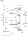
- Figure 1 shows a simplified, two-dimensional longitudinal sectional view of an arrangement ARG according to the invention with an output shaft SHB of a gearbox GER, which extends along an axis X.
- the gearbox GER is designed as a planetary gearbox EPG.
- the output shaft SHB is connected to a drive shaft SHN in a torsionally rigid and bending-resistant manner.
- the drive shaft SHN is connected to a working machine, in particular a mill MLL, in a torque-transmitting connection.
- the gearbox GER is supported on the working machine WMS by means of the connection of the output shaft SHB to the drive shaft SHN and by means of a torque support TSP for at least 90% - preferably completely - of the forces arising during operation.
- the output shaft SHB is connected to one axial end of the drive shaft SHN.
- a torque TRQ with a speed RVL is transmitted from the output shaft SHB to an input shaft short gear STN of the drive shaft SHN.
- the axial end of the drive shaft SHN which is connected to the output shaft SHB, is designed as a hollow shaft HLW.
- the axial end of the output shaft SHB has a stub STP, which is at least partially arranged in the hollow shaft HLW of the drive shaft SHN.
- the drive shaft SHN is modularly constructed such that the axial end of the drive shaft SHN is designed as a first axial section AX1 as a flange FLG, which is axially attached to a second axial section AX2 of the drive shaft SHN, wherein the flange FLG forms the end axial shaft section, which is designed as a hollow shaft HLW.
- the flange FLG is attached to the second axial section AX2 by means of screws SCR and is designed as a cast component, in particular made of metal.
- the drive shaft SHN has a radially inwardly projecting formation PTR in the area of the hollow shaft HLW design, wherein a holding element AFE is fastened to the axial end of the output shaft SHB designed as a stump STP by means of axially acting fastening means FXE screws SCR, such that the formation PTR is clamped in the area between the holding element AFE and an axial contact surface of the other output shaft SHB.
- the AFE retaining element is ring-shaped and formed as a single piece in the circumferential direction.
- a first radial drive shaft centering RN1 is provided at the axial end of the drive shaft SHN and a radial output shaft centering RB1 is provided at the axial end of the output shaft SHB to which the drive shaft SHN is connected, wherein the two centerings are in radial centering contact with each other.
- connection of the output shaft SHB to the drive shaft SHN is designed to be rigid, in that a second radial drive shaft centering RN2 is provided at the axial end of the drive shaft SHN, axially spaced from the first radial drive shaft centering RN1, wherein a second radial output shaft centering RB2 is provided at the axial end of the output shaft SHB, axially spaced from the first radial output shaft centering RB1, wherein the output shaft centerings RB1, RB2 and drive shaft centerings RN1, RN2 are assigned to one another in pairs to form two axially spaced centering pairs and are in radial centering contact with one another.
- Figure 2 shows a schematic representation of a simulation SIM of an arrangement ARG according to the invention running on a computer CMP - here on several computers CMP of a network WWB comprising a cloud CLD.
- the software installed on the computers CMP is a computer program product CPP which, when executed on at least one computer CMP, enables the user to influence or configure and gain knowledge based on the executed simulation SIM using the screen and keyboard interfaces, so that technical design decisions in particular can be supported and verified using the simulation.
Landscapes
- Engineering & Computer Science (AREA)
- General Engineering & Computer Science (AREA)
- Mechanical Engineering (AREA)
- Physics & Mathematics (AREA)
- Geometry (AREA)
- Theoretical Computer Science (AREA)
- General Physics & Mathematics (AREA)
- Mathematical Analysis (AREA)
- Mathematical Optimization (AREA)
- Pure & Applied Mathematics (AREA)
- Computer Hardware Design (AREA)
- Evolutionary Computation (AREA)
- Computational Mathematics (AREA)
- Shafts, Cranks, Connecting Bars, And Related Bearings (AREA)
- Structure Of Transmissions (AREA)
- General Details Of Gearings (AREA)
Description
- Die Erfindung betrifft eine Anordnung umfassend ein antriebsseitiges Getriebe mit einer Abtriebswelle des Getriebes, die sich entlang einer Achse erstreckt, und umfassend eine Arbeitsmaschine mit einer mit der Abtriebswelle drehsteif verbundenen Antriebswelle.
- Daneben umfasst die Erfindung auch ein computerimplementiertes Verfahren zur Simulation einer Anordnung und ein entsprechendes Computerprogrammprodukt zur Durchführung dieses Verfahrens mittels mindestens eines Computers.
- Derartige Anordnungen sind häufig raumgreifend und neigen infolge höherer Belastungen bei gleichzeitig geforderter Kompaktheit schnell zur Überlastung.
- Eine Anwendungsmöglichkeit für eine gattungsgemäße Anordnung ist in der
EP 2 989 351 A1 gezeigt. - Aus
US 2018/0251353 A1 ist eine als Hohlwelle ausgestaltete Antriebswelle eines Motors bekannt, die radial innen über eine Innenverzahnung mit einer radial außen vorgesehenen Kurzverzahnung einer Abtriebswelle eines über eine Drehmomentstütze abgestützten Getriebes drehfest gekoppelt ist. - Aus
CN 203 594 733 U ist ein Getriebe für einen Extruder bekannt, bei dem eine Antriebsleistung über Stirnradstufen an ein über eine Drehmomentstütze abgestütztes Planetengetriebe übertragen wird, dessen zweiteilige Ausgangswelle an unterschiedlichen Seiten des Getriebes herausragt, um die jeweiligen Extruderschnecken anzutreiben. Die mit einem Planetenträger des Planetengetriebes verbundene zweiteilige Ausgangswelle weist zwei über eine Kurzverzahnung drehfest miteinander verbundene Hohlwellen auf, mit denen die zugehörige Extruderschnecke über eine Verzahnung oder eine Flanschverschraubung befestigt werden kann. - Aus
EP 3 702 647 A1 ist ein Getriebe für eine Windkraftanlage bekannt, bei dem eine Antriebsleistung über eine Stirnradstufe von einem über eine Drehmomentstütze abgestütztes Planetengetriebe an einen Generator ausgeleitet wird, wobei die Stirnradstufe über eine Kurzverzahnung mit einer als Hohlwelle ausgestalteten Sonnenwelle drehfest gekoppelt ist. Die Stirnradstufe weist eine aus dem Getriebegehäuse herausragende Abtriebswelle auf, die als Vollwelle ausgestaltet ist. - Aus
US 2007/2950509 A1 ist ein Getriebe für eine Windkraftanlage bekannt, bei dem eine Antriebsleistung über einen Planetenträger eines über eine Drehmomentstütze abgestützten Planetengetriebes eingeleitet und über eine Sonnenwelle an einen Generator ausgeleitet wird, wobei die Sonnenwelle als Vollwelle ausgestaltet ist. - Ausgehend von den zuvor beschriebenen Problemen liegt der Erfindung die Aufgabe zugrunde, eine zuverlässige Anordnung eingangs definierter Art zu schaffen, die bei moderatem Raumbedarf den hohen anfallenden Lasten standhält.
- Zur Lösung der Aufgabe schlägt die Erfindung eine Anordnung der eingangs definierten Art vor, bei der das Getriebe an der Arbeitsmaschine mittels der Verbindung der Abtriebswelle mit der Antriebswelle und mittels einer Drehmomentstütze zu mindestens 90% der im Betrieb entstehenden Kräfte abgestützt ist, wobei die Verbindung der Abtriebswelle mit der Antriebswelle zur Abstützung von Querkräften biegesteif ausgebildet ist, wobei das axiale Ende der Antriebswelle als Hohlwelle ausgeführt ist, wobei das axiale Ende der Abtriebswelle einen Stumpf aufweist, der zumindest teilweise in der Hohlwelle der Antriebswelle angeordnet ist.
- Die Antriebswelle weist in dem Bereich der Ausbildung als Hohlwelle eine Ausformung auf, wobei an dem als Stumpf ausgebildeten axialen Ende der Abtriebswelle ein Halteelement mittels Befestigungsmitteln befestigt ist, derart, dass die Ausformung in dem Bereich zwischen dem Halteelement und einer axialen Anlagefläche der sonstigen Abtriebswelle eingeklemmt ist. Bevorzugt besteht das Halteelement aus Metall. Auf diese Weise kann der Flansch an der Abtriebswelle mittels des Halteelements angebracht werden und anschließend kann der Flansch an der Antriebswelle befestigt werden. Besonders zweckmäßig für die Einfachheit der Montage sowie für die Festigkeit und die Laufruhe kann bei der Anordnung der Erfindung das Halteelement, das besonders vorteilhaft ringförmig, also als Haltering ausgebildet sein kann, einteilig ausgeführt werden. Besonders bevorzugt ermöglicht die erfindungsgemäße Anordnung eine freie axiale Zugänglichkeit zu der Montageposition des Halteelements, insbesondere ohne, dass eine sich axial erstreckende Fortsetzung einer Welle eine teilbare - mindestens 2-teilige Ausführung des Halteelements erfordert.
- Die erfindungsgemäße Anordnung umfasst als Getriebe bevorzugt ein Planetengetriebe und ist bevorzugt Bestandteil einer Rollenpresse oder einer Mühle, z.B. einer Zuckermühle, bevorzugt mit Individualantrieb oder diverser anderer Anwendungen im Industriebereich.
- Die erfindungsgemäße Anordnung kann hinsichtlich des Getriebes als "wellenreitend gelagert" bezeichnet werden. Dies bedeutet, dass die Abtriebswelle des Getriebes oder Planetengetriebes auf der Antriebswelle der Arbeitsmaschine befestigt ist, derart, dass die Abtriebswelle und das Getriebes dort gegen Querkräfte abgestützt sind. Das Drehmoment am Getriebe bzw. Getriebegehäuse wird mittels einer Drehmomentstütze abgeleitet, z.B. indirekt oder direkt in ein Fundament eingeleitet. Die Ableitung des Drehmoments kann hierbei auch mittels benachbarter Maschinenelemente erfolgen, z.B. über die Arbeitsmaschine, an der die Drehmomentstütze angebracht ist. Die Drehmomentstütze ist hierbei an dem Getriebe derart angebracht, dass das Getriebe an einer axialen Drehung (bzgl. der Abtriebswelle) gehindert ist. Andere Freiheitsgrade der Bewegung werden von der Drehmomentstütze bevorzugt nicht eingeschränkt.
- Die Antriebswelle der Arbeitsmaschine ist insbesondere starr mit der Abtriebswelle des Getriebes gekoppelt, so dass vorzugsweise ein radialer Versatz und/oder Verkippbarkeit zwischen der Antriebswelle der Arbeitsmaschine und der Abtriebswelle des Getriebes eliminiert ist. Insbesondere sind die Drehachsen der Antriebswelle der Arbeitsmaschine und der Abtriebswelle des Getriebes koaxial zueinander ausgerichtet, so dass die Drehachsen der Antriebswelle der Arbeitsmaschine und der Abtriebswelle des Getriebes zusammenfallen können. Vorzugsweise ist im montierten Zustand auch eine axiale Relativbewegung der Antriebswelle der Arbeitsmaschine relativ zu der Abtriebswelle des Getriebes blockiert. Die Antriebswelle der Arbeitsmaschine und die Abtriebswelle des Getriebes können zueinander zentriert sein. In der Anordnung auftretende Drehmomente können dadurch nahezu vollständig, insbesondere zu mindestens 90%, über die Drehmomentstütze abgestützt sein. Ein von der Arbeitsmaschine über die Antriebswelle in das Getriebe eingeleitetes abzustützendes Drehmoment wird dadurch nicht an der Verbindungsstelle der Antriebswelle der Arbeitsmaschine mit der Abtriebswelle des Getriebes abgestützt, sondern über die Abtriebswelle des Getriebes abgeleitet und zu der Antriebswelle der Arbeitsmaschine beabstandet erst über die Drehmomentstütze abgestützt. Das von Arbeitsmaschine eingeleitete abzustützende Drehmoment kann dadurch über die einzelnen Verzahnungen des Getriebes weitergeleitet werden, bis es über die Drehmomentstütze abgestützt werden kann. Das Getriebe ist insbesondere als mindestens einstufiges, vorzugsweise mehrstufiges, Planetengetriebe ausgestaltet, von dem eine verzahnte Getriebekomponente, beispielsweise ein feststehendes Hohlrad, mit einem Getriebegehäuse fest verbunden ist, mit dem wiederum die Drehmomentstütze verbunden sein kann. Das von Arbeitsmaschine eingeleitete abzustützende Drehmoment wird dadurch über die einzelnen Verzahnungen des Getriebes bis an das Getriebegehäuse und die Drehmomentstütze geleitet und abgestützt, so dass bei einer guten Stabilität ein geringer Bauraumbedarf erreicht ist.
- Die Antriebswelle der Arbeitsmaschine ist insbesondere im Wesentlichen nur in einem Axialbereich, in dem die Antriebswelle die Abtriebswelle des Getriebes radial außen umgreift, als Hohlwelle ausgestaltet und im Übrigen als Vollwelle ausgestaltet. Der die Hohlwelle ausbildende Bereich der Antriebswelle ist beispielsweise als zylindrische Vertiefung ausgestaltete, die an einer axialen Stirnseite, beispielsweise durch Drehen, koaxial zur Drehachse der Antriebswelle eingebracht ist. Vorzugsweise ist die Abtriebswelle des Getriebes als Vollwelle ausgestaltete. Eine in axialer Richtung durchgehende zylindrische koaxialer zur Drehachse verlaufender Öffnung kann in der Abtriebswelle vermieden werden, so dass die Abtriebswelle auch bei einem im Vergleich zur Antriebswelle der Arbeitsmaschine kleineren Nenndurchmesser die auftretenden Lasten ohne signifikante Durchbiegungen übertragen kann.
- Die Abtriebswelle stellt insbesondere die letzte in Drehmomentrichtung noch dem Getriebe zuzurechnende Welle dar, die insbesondere aus einem Getriebegehäuse des Getriebes herausragt oder mit der in das Getriebegehäuse des Getriebes hineinragende Antriebswelle verbunden ist. Die Abtriebswelle kann einen Leistungsausgang des Getriebes darstellen. Die Antriebswelle stellt insbesondere die erste in Drehmomentrichtung noch der Arbeitsmaschine zuzurechnende Welle dar, die insbesondere aus einem Gehäuse der Arbeitsmaschine herausragt oder mit der in das Gehäuse der Arbeitsmaschine hineinragende Abtriebswelle verbunden ist. Die Abtriebswelle kann einen Leistungseingang der Arbeitsmaschine darstellen.
- Durch die biegesteife Verbindung der Antriebswelle der Arbeitsmaschine mit der Abtriebswelle des Getriebes kann eine Durchbiegung quer zur Drehachse vermieden werden. Stattdessen können insbesondere die auftretenden Querkräfte über das Getriebe an die Drehmomentstütze abgetragen und räumlich versetzt zur Verbindungstelle der Antriebswelle der Arbeitsmaschine mit der Abtriebswelle des Getriebes abgestützt werden. Dies ermöglicht es eine weitere Abstützung im Bereich der Verbindungstelle der Antriebswelle der Arbeitsmaschine mit der Abtriebswelle des Getriebes einzusparen.
- Insbesondere ist die Antriebswelle an der Abtriebswelle über eine Radialabstützung zur Abtragung von Querkräften abgestützt. Die Radialabstützung ist beispielsweise durch eine Stufe oder einen Absatz ausgebildet, an der die Antriebswelle an der Abtriebswelle vorzugsweise flächig anliegen kann. Die Radialabstützung ist insbesondere Teil einer Zentrierung der Antriebswelle an der Abtriebswelle. Für die biegesteife Verbindung kann daher die quer zur Drehachse der Antriebswelle der Arbeitsmaschine und/oder der Abtriebswelle des Getriebes, also insbesondere im Wesentlichen in radialer Richtung, wirkende Radialabstützung zwischen der Antriebswelle der Arbeitsmaschine und/oder der Abtriebswelle des Getriebes vorgesehen sein, über die in radialer Richtung auftretende Querkräfte abgestützt und über das Getriebe an die Drehabstützung abgeleitet werden können.
- Vorzugsweise ist die Antriebswelle an der Abtriebswelle über eine Axialabstützung zur Abtragung von Längskräften abgestützt. Die Axialabstützung ist beispielsweise durch eine Stufe oder einen Absatz ausgebildet, an der die Antriebswelle an der Abtriebswelle vorzugsweise flächig anliegen kann. Die Axialabstützung ist insbesondere Teil einer Zentrierung der Antriebswelle an der Abtriebswelle. Für die biegesteife Verbindung kann daher die längs zur Drehachse der Antriebswelle der Arbeitsmaschine und/oder der Abtriebswelle des Getriebes, also insbesondere im Wesentlichen in axialer Richtung, wirkende Axialabstützung zwischen der Antriebswelle der Arbeitsmaschine und/oder der Abtriebswelle des Getriebes vorgesehen sein, über die in axialer Richtung auftretende Längskräfte abgestützt und über das Getriebe an die Drehabstützung abgeleitet werden können.
- Bevorzugt ist die Anordnung derart ausgebildet, dass das Getriebe an der Arbeitsmaschine mittels der Verbindung der Abtriebswelle mit der Antriebswelle und mittels der Drehmomentstütze vollständig gegen die im Betrieb entstehenden Kräfte abgestützt ist.
- Eine Eigenschaft dieser Anordnung ist, dass die die Arbeitsmaschinenwelle und die Getriebewelle verbindende Element neben dem Antriebs-Drehmoment auch die Gewichtslasten des Getriebes sowie weiterer Komponenten (Motor, Kupplung, etc.) übertragen muss. Hierdurch entstehen an der Verbindung hohe Biegewechsellasten.
- Gemäß der Erfindung ist es möglich, die für die Dimensionierung kritische Kurzverzahnung auf dem maximal möglichen Durchmesser der Abtriebswelle bzw. des Stumpfs vorzusehen. Hierbei ist es besonders zweckmäßig, wenn der Außendurchmesser der Abtriebswellenkurzverzahnung zwischen 85 - 100% des Außendurchmesser des Bereichs der Abtriebswelle aufweist, der an den Stumpf angrenzt. Im Sinne der Erfindung bezeichnet der Begriff "Stumpf" nur einen endseitigen Wellenabschnitt, der insbesondere nicht - gegenüber der übrigen Welle - einen anderen Durchmesser aufweisen muss oder in sonstiger Weise zwingend anders ausgebildet ist. Da über diese Verbindung nicht nur das Antriebs-Drehmoment sondern auch Querkräfte übertragen werden.
- Eine vorteilhafte Weiterbildung der Erfindung sieht vor, dass die Antriebswelle modular aufgebaut ist, derart, dass das axiale Ende der Antriebswelle als ein erster Axialabschnitt als ein Flansch ausgebildet ist, der axial an einem zweiten Axialabschnitt der Antriebswelle angebracht ist, wobei der Flansch den endseitigen axialen Wellenabschnitt bildet, der als Hohlwelle ausgebildet ist. Insbesondere ermöglicht dieser modulare Aufbau den Einsatz der erfindungsgemäßen Anordnung mit angrenzenden Standardkomponenten. Standardmäßig kann zur Verbindung von Getriebe- und Arbeitsmaschinenwelle ein Flansch eingesetzt werden. Der Flansch wird bevorzugt mit der Antriebswelle bzw. Arbeitsmaschinenwelle verschraubt.
- Besonders kostengünstig und zweckmäßig kann der Flansch als Gussbauteil, insbesondere aus Metall, ausgebildet sein. Bei einer herkömmlichen Anordnung der eingangs definierter Art ist es unter den entsprechend hohen Belastungen nur möglich, den Flansch aus einem höherfesten Material herzustellen. Die Erfindung eröffnet auch den Weg einer Ausführung als Gussbauteil. Ein geschmiedetes Teil ist deutlich teurer als eine vergleichbare Gussvariante.
- Damit die erfindungsgemäße Anordnung möglichst gut radial ausgerichtet ist, kann an einem axialen Ende der Antriebswelle, mindestens eine erste radiale Antriebswellenzentrierung vorgesehen sein, wobei an einem axialen Ende der Abtriebswelle, an dem die Antriebswelle angeschlossen wird, mindestens eine radiale Abtriebswellenzentrierung vorgesehen ist, wobei die beiden Zentrierungen radial zentrierend miteinander in Kontakt stehen.
- Eine besonders vorteilhafte Möglichkeit diese Biegesteifigkeit herzustellen besteht darin, dass an dem axialen Ende der Antriebswelle, eine zu der ersten radialen Antriebswellenzentrierung axial beabstandete zweite radiale Antriebswellenzentrierung vorgesehen ist, wobei an dem axialen Ende der Abtriebswelle, eine zu der ersten radialen Abtriebswellenzentrierung axial beabstandete zweite radiale Abtriebswellenzentrierung vorgesehen ist, wobei die Abtriebswellenzentrierungen und Antriebswellenzentrierungen paarweise zueinander zu zwei axial beabstandeten Zentrierungspaaren zugeordnet sind und jeweils radial zentrierend miteinander in Kontakt stehen.
- Getriebeseitig wird der Flansch bei der Montage bevorzugt in die Abtriebswelle gesteckt, welche besonders bevozugt als Hohlwelle mit der innenliegenden Kurzverzahnung sowie zwei Zentriersitzen ausgeführt ist. Die Biegelasten werden so über die Zentriersitze, die Drehmomente über die Kurzverzahnung übertragen. Die axiale Verschiebung der Komponenten zueinander wird durch das Haltelement, bevorzugt ausgebildet als Haltering, verhindert. Dieser kann in Umfangsrichtung ungeteilt ausgeführt werden.
- Dimensionierendes Kriterium für den Flansch ist der maximal mögliche Innendurchmesser an der Getriebeabtriebswelle. Dieser ist über ein Mindestdickenverhältnis an den Außendurchmesser der Welle gekoppelt. Mit steigender Drehmomentdichte wird der Außendurchmesser der Getriebeabtriebswelle immer kleiner, wodurch auch der mögliche Innendurchmesser kleiner wird. Dies führt ebenfalls zu einem kleineren Zapfen an dem Flansch, wodurch die auftretenden Biegewechsellasten zum dimensionierenden Kriterium werden. Hier entfaltet die erfindungsgemäße Lösung ihre Stärken.
- Das bevorzugte Einsatzgebiet der Erfindung liegt im Bereich von Getrieben, wie sie an Mühlen, z.B. Zuckermühlen vorgesehen sind. Diese Getriebe sind bevorzugt als Planetengetriebe ausgebildet.
- Vorteile und Ausgestaltungen der Erfindung, die einzeln oder in Kombination miteinander einsetzbar sind, sind Gegenstand der Unteransprüche.
- Eine nicht beanspruchte Ausführungsform bezieht sich auch auf ein computerimplementiertes Verfahren zur Simulation eine Anordnung nach mindestens einer durch die Ansprüche definierte Merkmalskombination, bei dem insbesondere die einzelnen Bestandteile der Anordnung in einer Simulationsumgebung als computersimulierte Teile virtuell abgebildet sind und deren physikalischen Wechselwirkungen in der Simulationsumgebung vollständig oder teilweise analysiert werden. Dementsprechend umfasst die Ausführungsform einerseits das körperliche Gebilde mit den erfindungsgemäßen Merkmalen und andererseits auch einen digitalen Zwilling, wie er beispielsweise zum Zwecke der Simulation der Anordnung bzw. des Betriebes der Anordnung mittels mindestens eines Computers eingesetzt wird. Daneben bezieht sich die Ausführungsform auch auf ein nicht beanspruchtes entsprechendes Computerprogrammprodukt. Das Computerprogrammprodukt umfasst Befehle, die bei der Ausführung des Computerprogrammprodukts durch einen Computer diesen veranlassen, die einzelnen Bestandteile der erfindungsgemäßen Anordnung in einer Simulationsumgebung als computersimulierte Teile virtuell abzubilden und deren physikalischen Wechselwirkungen in der Simulationsumgebung vollständig oder teilweise zu analysieren, um das computerimplementierte Verfahren auszuführen.
- Ein Aspekt betrifft ferner ein nicht beanspruchtes Datenagglomerat mit in einer gemeinsamen Datei zusammengefassten oder über verschiedene Dateien verteilten Datenpaketen zur Abbildung der dreidimensionalen Formgestaltung und/oder der Wechselwirkungen sämtlicher in der Anordnung, die wie vorstehend beschrieben aus- und weitergebildet sein kann, vorgesehenen Bestandteile, wobei die Datenpakete dazu hergerichtet sind bei einer Verarbeitung durch eine Datenverarbeitungseinrichtung eine additive Herstellung der Bestandteile der Anordnung, die wie vorstehend beschrieben aus- und weitergebildet sein kann, insbesondere durch 3D-Druck, und/oder eine Simulation der Funktionsweise der Anordnung, die wie vorstehend beschrieben aus- und weitergebildet sein kann, durchzuführen. Das Datenagglomerat kann in der Art eines sogenannten "digital twin" eine virtuelle Verkörperung der erfindungsgemäßen Anordnung, darstellen, die eine virtuelle Untersuchung in Form einer Simulation oder eine reale Vergegenständlichung mit Hilfe eines additiven Fertigungsverfahrens ermöglicht. Hierbei kann insbesondere jeweils ein Datenpaket einen separat ausgeführten Bestandteil der erfindungsgemäßen Anordnung abbilden, so dass die einzelnen Bestandteile in ihrer Relativlage und/oder Relativbeweglichkeit leicht tatsächlich und/oder virtuell zusammengesetzt werden können, um die erfindungswesentlichen Wechselwirkungen zu realisieren. Dies ermöglicht eine kostengünstige Herstellung von Prototypen und/oder computerbasierten Simulationen, um die Funktionsweise der erfindungsgemäßen Anordnung zu studieren, Probleme im konkreten Anwendungsfall zu identifizieren und Verbesserungen zu finden. Vorzugsweise können einzelne und/oder sämtliche Datenpakete des Datenagglomerats in die Simulationsumgebung des computerimplementierten Verfahrens und/oder das Computerprogrammprodukt, beispielsweise als Teil einer Datenbank oder Library, geladen und zur virtuellen Abbildung als computersimulierte Teile und/oder deren physikalischen Wechselwirkungen hochgeladen werden.
- Weitere Merkmale, Eigenschaften und Vorteile der vorliegenden Erfindung ergeben sich aus der nachfolgenden Beschreibung unter Bezugnahme auf die Figuren. Darin zeigen schematisch:
- Figur 1
- eine vereinfachte, zweidimensionale Längsschnittdarstellung einer erfindungsgemäßen Anordnung,
- Figur 2
- eine schematische Darstellung einer auf einem Computer ablaufenden Simulation einer Anordnung nach der Erfindung, Computerprogrammprodukt.
- In den Ausführungsbeispielen und Figuren können gleiche oder gleich wirkende Elemente jeweils mit den gleichen Bezugszeichen versehen sein. Die dargestellten Elemente und deren Größenverhältnisse untereinander sind grundsätzlich nicht als maßstabsgerecht anzusehen, vielmehr können einzelne Elemente, zur besseren Darstellbarkeit und/oder zum besseren Verständnis im Verhältnis größer dimensioniert dargestellt sein.
-
Figur 1 zeigt eine vereinfachte, zweidimensionale Längsschnittdarstellung einer erfindungsgemäßen Anordnung ARG mit einer Abtriebswelle SHB eines Getriebes GER, die sich entlang einer Achse X erstreckt. Das Getriebe GER ist als Planetengetriebe EPG ausgebildet. Die Abtriebswelle SHB ist mit einer Antriebswelle SHN drehsteif und biegesteif verbundenen. Die Antriebswelle SHN steht mit einer Arbeitsmaschine, insbesondere einer Mühle MLL in drehmomentübertragender Verbindung. Das Getriebe GER ist an der Arbeitsmaschine WMS mittels der Verbindung der Abtriebswelle SHB mit der Antriebswelle SHN und mittels einer Drehmomentstütze TSP zu mindestens 90% - bevorzugt vollständig - der im Betrieb entstehenden Kräfte abgestützt. Kräfte BTQ (insbesondere Biegelasten, Querkräfte) aus dem nicht dargestellten Antrieb des Getriebes GER, werden in die Antriebswelle SHN und die Drehmomentstütze TSP (hier insbesondere Kräfte aus einem Differenzdrehmoment infolge des Getriebes GER) eingeleitet. Das Drehmoment am Getriebe GER bzw. Getriebegehäuse wird mittels der Drehmomentstütze TSP abgeleitet, z.B. indirekt oder direkt in ein Fundament FDG eingeleitet. - An einem axialen Ende der Antriebswelle SHN ist die Abtriebswelle SHB angeschlossen. Mittels einer Abtriebswellenkurzverzahnung STB wird ein Drehmoment TRQ mit einer Drehzahl RVL übertragen von der Abtriebswelle SHB auf eine Antriebswellenkurzverzahnung STN der Antriebswelle SHN.
- Das axiale Ende der Antriebswelle SHN, das an der Abtriebswelle SHB angeschlossen ist, ist als Hohlwelle HLW ausgeführt. Hierbei weist das axiale Ende der Abtriebswelle SHB einen Stumpf STP auf, der zumindest teilweise in der Hohlwelle HLW der Antriebswelle SHN angeordnet ist.
- Die Antriebswelle SHN ist modular aufgebaut, derart, dass das axiale Ende der Antriebswelle SHN als ein erster Axialabschnitt AX1 als ein Flansch FLG ausgebildet ist, der axial an einem zweiten Axialabschnitt AX2 der Antriebswelle SHN angebracht ist, wobei der Flansch FLG den endseitigen axialen Wellenabschnitt bildet, der als Hohlwelle HLW ausgebildet ist. Der Flansch FLG ist an dem zweiten Axialabschnitt AX2 mittels Schrauben SCR befestigt und als Gussbauteil, insbesondere aus Metall, ausgebildet.
- Die Antriebswelle SHN weist in dem Bereich der Ausbildung als Hohlwelle HLW eine radial nach innen ragende Ausformung PTR auf, wobei an dem als Stumpf STP ausgebildeten axialen Ende der Abtriebswelle SHB ein Halteelement AFE mittels axial wirkenden Befestigungsmitteln FXE Schrauben SCR befestigt ist, derart, dass die Ausformung PTR in dem Bereich zwischen dem Halteelement AFE und einer axialen Anlagefläche der sonstigen Abtriebswelle SHB eingeklemmt ist.
- Das Halteelement AFE ist ringförmig und in Umfangsrichtung einteilig ausgebildet.
- An dem axialen Ende der Antriebswelle SHN ist eine erste radiale Antriebswellenzentrierung RN1 vorgesehen und an dem axialen Ende der Abtriebswelle SHB, an dem die Antriebswelle SHN angeschlossen wird, ist eine radiale Abtriebswellenzentrierung RB1 vorgesehen ist, wobei die beiden Zentrierungen radial zentrierend miteinander in Kontakt stehen.
- Die Verbindung der Abtriebswelle SHB mit der Antriebswelle SHN ist biegesteif ausgebildet, dadurch, dass an dem axialen Ende der Antriebswelle SHN, eine zu der ersten radialen Antriebswellenzentrierung RN1 axial beabstandete zweite radiale Antriebswellenzentrierung RN2 vorgesehen ist, wobei an dem axialen Ende der Abtriebswelle SHB, eine zu der ersten radialen Abtriebswellenzentrierung RB1 axial beabstandete zweite radiale Abtriebswellenzentrierung RB2 vorgesehen ist, wobei die Abtriebswellenzentrierungen RB1, RB2 und Antriebswellenzentrierungen RN1, RN2 paarweise zueinander zu zwei axial beabstandeten Zentrierungspaaren zugeordnet sind und jeweils radial zentrierend miteinander in Kontakt stehen.
-
Figur 2 zeigt eine schematische Darstellung einer auf einem Computer CMP - hier auf mehreren Computern CMP eines Netzwerks WWB umfassend eine Cloud CLD - ablaufenden Simulation SIM einer Anordnung ARG nach der Erfindung. Die auf den Computern CMP installierte Software ist ein Computerprogrammprodukt CPP, das bei Ausführung auf mindestens einem Computer CMP dem Benutzer mittels Schnittstellen Bildschirm, Tastatur eine Einflussnahme bzw. Konfiguration und einen Erkenntnisgewinn auf Basis der ausgeführten Simulation SIM ermöglicht, so dass insbesondere technische Gestaltungsentscheidungen mittels der Simulation unterstützt und verifiziert werden können. - Obwohl die Erfindung im Detail durch das bevorzugte Ausführungsbeispiel näher illustriert und beschrieben wurde, ist die Erfindung nicht durch die offenbarten Beispiele eingeschränkt. Variationen hiervon können vom Fachmann abgeleitet werden, ohne den Schutzumfang der Erfindung, wie er durch die nachfolgenden Patentansprüche definiert wird, zu verlassen.
Claims (12)
- Anordnung (ARG) umfassend ein antriebsseitiges Getriebe (GER) mit einer Abtriebswelle (SHB) des Getriebes (GER), die sich entlang einer Achse (X) erstreckt, und umfassend eine Arbeitsmaschine (WMS) mit einer mit der Abtriebswelle (SHB) drehsteif verbundenen Antriebswelle (SHN),wobei das Getriebe (GER) an der Arbeitsmaschine (WMS) mittels der Verbindung der Abtriebswelle (SHB) mit der Antriebswelle (SHN) und mittels einer Drehmomentstütze (TSP) zu mindestens 90% der im Betrieb entstehenden Kräfte abgestützt ist, wobei die Verbindung der Abtriebswelle (SHB) mit der Antriebswelle (SHN) zur Abstützung von Querkräften biegesteif ausgebildet ist,wobei das axiale Ende der Antriebswelle (SHN) als Hohlwelle (HLW) ausgeführt ist,wobei das axiale Ende der Abtriebswelle (SHB) einen Stumpf (STP) aufweist, der zumindest teilweise in der Hohlwelle (HLW) der Antriebswelle (SHN) angeordnet ist dadurch gekennzeichnet, dassdie Antriebswelle (SHN) in dem Bereich der Ausbildung als Hohlwelle (HLW) eine Ausformung (PTR) aufweist,wobei an dem als Stumpf (STP) ausgebildeten axialen Ende der Abtriebswelle (SHB) ein Halteelement (AFE) mittels Befestigungsmitteln (FXE) befestigt ist, derart, dass die Ausformung (PTR) in dem Bereich zwischen dem Halteelement (AFE) und einer axialen Anlagefläche der sonstigen Abtriebswelle (SHB) eingeklemmt ist.
- Anordnung (ARG) nach Anspruch 1, wobei die Antriebswelle (SHN) an der Abtriebswelle (SHB) über eine Radialabstützung zur Abtragung von Querkräften abgestützt ist.
- Anordnung (ARG) nach Anspruch 1 oder 2, wobei die Antriebswelle (SHN) an der Abtriebswelle (SHB) über eine Axialabstützung zur Abtragung von Längskräften abgestützt ist.
- Anordnung (ARG) nach einem der vorhergehenden Ansprüche, wobei die Antriebswelle (SHN) modular aufgebaut ist, derart, dass das axiale Ende der Antriebswelle (SHN) als ein erster Axialabschnitt (AX1) als ein Flansch (FLG) ausgebildet ist, der axial an einem zweiten Axialabschnitt (AX2) der Antriebswelle (SHN) angebracht ist, wobei der Flansch (FLG) den endseitigen axialen Wellenabschnitt bildet, der als Hohlwelle (HLW) ausgebildet ist.
- Anordnung (ARG) nach Anspruch 4, wobei das Halteelement (AFE) rund oder ringförmig ausgebildet ist.
- Anordnung (ARG) nach Anspruch 4 oder 5, wobei der Flansch (FLG) als Gussbauteil ausgebildet ist.
- Anordnung (ARG) nach einem der vorhergehenden Ansprüche, wobei an einem axialen Ende der Abtriebswelle (SHB), an dem die Antriebswelle (SHN) angeschlossen wird, eine Abtriebswellenkurzverzahnung (STB) vorgesehen sind,
wobei an einem axialen Ende der Antriebswelle (SHN), an dem die Abtriebswelle (SHB) angeschlossen wird, eine Antriebswellenkurzverzahnung (STN) vorgesehen sind. - Anordnung (ARG) nach einem der vorhergehenden Ansprüche, wobei das Getriebe (GER) an der Arbeitsmaschine (WMS) mittels der Verbindung der Abtriebswelle (SHB) mit der Antriebswelle (SHN) und mittels der Drehmomentstütze (TSP) vollständig gegen die im Betrieb entstehenden Kräfte abgestützt ist.
- Anordnung (ARG) nach mindestens einem der vorhergehenden Ansprüche, wobei an einem axialen Ende der Antriebswelle (SHN), mindestens eine erste radiale Antriebswellenzentrierung (RN1) vorgesehen ist,
wobei an einem axialen Ende der Abtriebswelle (SHB), an dem die Antriebswelle (SHN) angeschlossen wird, mindestens eine radiale Abtriebswellenzentrierung (RB1) vorgesehen ist, wobei die beiden Zentrierungen radial zentrierend miteinander in Kontakt stehen. - Anordnung (ARG) nach Anspruch 9, wobei an dem axialen Ende der Antriebswelle (SHN), eine zu der ersten radialen Antriebswellenzentrierung (RN1) axial beabstandete zweite radiale Antriebswellenzentrierung (RN2) vorgesehen ist,
wobei an dem axialen Ende der Abtriebswelle (SHB), eine zu der ersten radialen Abtriebswellenzentrierung (RB1) axial beabstandete zweite radiale Abtriebswellenzentrierung (RB2) vorgesehen ist, wobei die Abtriebswellenzentrierungen (RB1, RB2) und Antriebswellenzentrierungen (RN1, RN2) paarweise zueinander zu zwei axial beabstandeten Zentrierungspaaren zugeordnet sind und jeweils radial zentrierend miteinander in Kontakt stehen. - Anordnung (ARG) nach mindestens einem der vorhergehenden Ansprüche, wobei die Abtriebswelle (SHB) und/oder die Antriebswelle (SHN) und/oder die Drehmomentstütze (TSP) aus Metall bestehen.
- Anordnung (ARG) nach Anspruch 4, wobei der Flansch (FLG) aus Metall besteht.
Applications Claiming Priority (2)
| Application Number | Priority Date | Filing Date | Title |
|---|---|---|---|
| EP20204725.4A EP3992498A1 (de) | 2020-10-29 | 2020-10-29 | Anordnung mit einem getriebe und einer arbeitsmaschine, verfahren zur simulation |
| PCT/EP2021/079606 WO2022090187A1 (de) | 2020-10-29 | 2021-10-26 | Anordnung mit einem getriebe und einer arbeitsmaschine, verfahren zur simulation |
Publications (3)
| Publication Number | Publication Date |
|---|---|
| EP4237705A1 EP4237705A1 (de) | 2023-09-06 |
| EP4237705C0 EP4237705C0 (de) | 2024-12-04 |
| EP4237705B1 true EP4237705B1 (de) | 2024-12-04 |
Family
ID=73039907
Family Applications (2)
| Application Number | Title | Priority Date | Filing Date |
|---|---|---|---|
| EP20204725.4A Withdrawn EP3992498A1 (de) | 2020-10-29 | 2020-10-29 | Anordnung mit einem getriebe und einer arbeitsmaschine, verfahren zur simulation |
| EP21799266.8A Active EP4237705B1 (de) | 2020-10-29 | 2021-10-26 | Anordnung mit einem getriebe und einer arbeitsmaschine, verfahren zur simulation |
Family Applications Before (1)
| Application Number | Title | Priority Date | Filing Date |
|---|---|---|---|
| EP20204725.4A Withdrawn EP3992498A1 (de) | 2020-10-29 | 2020-10-29 | Anordnung mit einem getriebe und einer arbeitsmaschine, verfahren zur simulation |
Country Status (4)
| Country | Link |
|---|---|
| US (1) | US20240328500A1 (de) |
| EP (2) | EP3992498A1 (de) |
| CN (1) | CN116438392A (de) |
| WO (1) | WO2022090187A1 (de) |
Family Cites Families (19)
| Publication number | Priority date | Publication date | Assignee | Title |
|---|---|---|---|---|
| DE4024257A1 (de) * | 1990-07-31 | 1992-02-06 | Wittenstein Manfred | Getriebe mit einer nach aussen fuehrenden an- oder abtriebswelle |
| JP4178918B2 (ja) * | 2002-11-12 | 2008-11-12 | 株式会社日立製作所 | フランジカップリング |
| WO2007127430A2 (en) | 2006-04-27 | 2007-11-08 | Fatigue Technology, Inc. | Alignment device and methods of using the same |
| DE102006027543A1 (de) * | 2006-06-14 | 2007-12-20 | Nordex Energy Gmbh | Windenergieanlage mit einem Rotor |
| CN102619888B (zh) * | 2011-01-31 | 2015-05-27 | 华锐风电科技(集团)股份有限公司 | 动力传输连接法兰盘和风力发电机组 |
| DE102011081861A1 (de) * | 2011-05-17 | 2012-11-22 | Winergy Ag | Antriebssystem für eine Windkraftanlage |
| JP5854259B2 (ja) * | 2011-06-20 | 2016-02-09 | 西芝電機株式会社 | 回転電機 |
| CN203082049U (zh) * | 2012-12-21 | 2013-07-24 | 上海大郡动力控制技术有限公司 | 减少定位误差的主动轴与被动轴的连接结构 |
| DE102013212464A1 (de) | 2013-06-27 | 2014-12-31 | Siemens Aktiengesellschaft | Planetengetriebe |
| CN203594733U (zh) * | 2013-12-19 | 2014-05-14 | 天津市祥威传动设备有限公司 | 一种挤塑机用行星减速器 |
| WO2015125246A1 (ja) * | 2014-02-20 | 2015-08-27 | 三菱重工コンプレッサ株式会社 | 回転機械システム |
| CN205534133U (zh) * | 2016-04-18 | 2016-08-31 | 河北钢铁股份有限公司承德分公司 | 一种斗轮减速机和斗轮轴的联接装置 |
| US10464791B2 (en) * | 2017-03-06 | 2019-11-05 | Cameron International Corporation | Drawworks systems and methods |
| JP6695305B2 (ja) * | 2017-06-12 | 2020-05-20 | 日立建機株式会社 | 作業車両の走行装置 |
| JP2019076823A (ja) * | 2017-10-23 | 2019-05-23 | 住友金属鉱山株式会社 | 連結構造体 |
| CN207999454U (zh) * | 2018-01-26 | 2018-10-23 | 重庆智寰传动科技发展有限公司 | 用于连接电机与变速箱输入轴的转接头 |
| ES2927327T3 (es) * | 2019-02-27 | 2022-11-04 | Moventas Gears Oy | Sistema de engranajes |
| FI3789625T3 (fi) * | 2019-09-06 | 2023-03-28 | Flender Gmbh | Laippajärjestely, vaihteisto, sähkömoottori, tuulivoimala ja teollisuussovellus |
| CN211231324U (zh) * | 2019-09-30 | 2020-08-11 | 费赛恩流体技术(合肥)有限公司 | 一种搅拌机可拆卸式联轴器 |
-
2020
- 2020-10-29 EP EP20204725.4A patent/EP3992498A1/de not_active Withdrawn
-
2021
- 2021-10-26 CN CN202180073574.XA patent/CN116438392A/zh active Pending
- 2021-10-26 EP EP21799266.8A patent/EP4237705B1/de active Active
- 2021-10-26 US US18/034,544 patent/US20240328500A1/en active Pending
- 2021-10-26 WO PCT/EP2021/079606 patent/WO2022090187A1/de not_active Ceased
Also Published As
| Publication number | Publication date |
|---|---|
| CN116438392A (zh) | 2023-07-14 |
| US20240328500A1 (en) | 2024-10-03 |
| EP4237705A1 (de) | 2023-09-06 |
| EP4237705C0 (de) | 2024-12-04 |
| WO2022090187A1 (de) | 2022-05-05 |
| EP3992498A1 (de) | 2022-05-04 |
Similar Documents
| Publication | Publication Date | Title |
|---|---|---|
| DE102007004709B4 (de) | Leichtbau-Stirnraddifferential in Dünnblechbauweise | |
| EP2054263B1 (de) | Übertragungsvorrichtung für einen fahrzeugsitz | |
| DE102007061322B4 (de) | Exzentergetriebe und Verfahren zum Übertragen einer Drehkraft durch das Exzentergetriebe | |
| EP2076682B1 (de) | Kupplungsvorrichtung | |
| EP2775165B1 (de) | Elektromechanischer Dämpfer | |
| EP2184514B1 (de) | Spannungswellengetriebe | |
| DE102012103146A1 (de) | Lenkgetriebe | |
| WO2016155715A1 (de) | Zahnrad für ein zahnradgetriebe | |
| EP3464894B1 (de) | Windkraftgetriebe | |
| EP3734112A1 (de) | Planetengetriebe | |
| DE2940323A1 (de) | Doppelschraegverzahntes, zweistufiges stirnraedergetriebe | |
| DE19957062B4 (de) | Kupplungskombination | |
| EP1529144A1 (de) | Verriegelungseinrichtung für fahrzeuge, insbesondere für flugzeuge | |
| WO2023186862A1 (de) | Antriebsanordnung | |
| EP3810959B1 (de) | Getriebebaureihe | |
| EP4474667B1 (de) | Verstellantrieb mit einer sicherheitskupplung | |
| DE102019111310A1 (de) | Aktiver Wankstabilisator | |
| WO2022090187A1 (de) | Anordnung mit einem getriebe und einer arbeitsmaschine, verfahren zur simulation | |
| WO2024200702A1 (de) | Planetengetriebe mit in planetenträger gelagertem sonnenrad | |
| DE3201445A1 (de) | "elektrischer anlasser fuer brennkraftmaschinen" | |
| DE102018123116A1 (de) | System aus Rotorwelle und Abtriebswelle, Abtriebswelle und Verfahren zum Herstellen eines Systems aus Rotorwelle und Abtriebswelle | |
| DE102017112924A1 (de) | Planetengetriebe | |
| DE102012212735B4 (de) | Mehrteilige Schwungmasse | |
| EP4100666B1 (de) | Wendegetriebeeinheit | |
| DE102009028411A1 (de) | Exzenter-Differential-Untersetzungsgetriebe |
Legal Events
| Date | Code | Title | Description |
|---|---|---|---|
| STAA | Information on the status of an ep patent application or granted ep patent |
Free format text: STATUS: UNKNOWN |
|
| STAA | Information on the status of an ep patent application or granted ep patent |
Free format text: STATUS: THE INTERNATIONAL PUBLICATION HAS BEEN MADE |
|
| PUAI | Public reference made under article 153(3) epc to a published international application that has entered the european phase |
Free format text: ORIGINAL CODE: 0009012 |
|
| STAA | Information on the status of an ep patent application or granted ep patent |
Free format text: STATUS: REQUEST FOR EXAMINATION WAS MADE |
|
| 17P | Request for examination filed |
Effective date: 20230427 |
|
| AK | Designated contracting states |
Kind code of ref document: A1 Designated state(s): AL AT BE BG CH CY CZ DE DK EE ES FI FR GB GR HR HU IE IS IT LI LT LU LV MC MK MT NL NO PL PT RO RS SE SI SK SM TR |
|
| DAV | Request for validation of the european patent (deleted) | ||
| DAX | Request for extension of the european patent (deleted) | ||
| GRAP | Despatch of communication of intention to grant a patent |
Free format text: ORIGINAL CODE: EPIDOSNIGR1 |
|
| STAA | Information on the status of an ep patent application or granted ep patent |
Free format text: STATUS: GRANT OF PATENT IS INTENDED |
|
| GRAJ | Information related to disapproval of communication of intention to grant by the applicant or resumption of examination proceedings by the epo deleted |
Free format text: ORIGINAL CODE: EPIDOSDIGR1 |
|
| STAA | Information on the status of an ep patent application or granted ep patent |
Free format text: STATUS: REQUEST FOR EXAMINATION WAS MADE |
|
| INTG | Intention to grant announced |
Effective date: 20240709 |
|
| RIC1 | Information provided on ipc code assigned before grant |
Ipc: F16D 1/00 20060101ALI20240628BHEP Ipc: F16H 57/023 20120101ALI20240628BHEP Ipc: F16H 57/00 20120101ALI20240628BHEP Ipc: F16H 57/025 20120101AFI20240628BHEP |
|
| INTC | Intention to grant announced (deleted) | ||
| GRAP | Despatch of communication of intention to grant a patent |
Free format text: ORIGINAL CODE: EPIDOSNIGR1 |
|
| STAA | Information on the status of an ep patent application or granted ep patent |
Free format text: STATUS: GRANT OF PATENT IS INTENDED |
|
| GRAS | Grant fee paid |
Free format text: ORIGINAL CODE: EPIDOSNIGR3 |
|
| INTG | Intention to grant announced |
Effective date: 20240826 |
|
| GRAA | (expected) grant |
Free format text: ORIGINAL CODE: 0009210 |
|
| STAA | Information on the status of an ep patent application or granted ep patent |
Free format text: STATUS: THE PATENT HAS BEEN GRANTED |
|
| AK | Designated contracting states |
Kind code of ref document: B1 Designated state(s): AL AT BE BG CH CY CZ DE DK EE ES FI FR GB GR HR HU IE IS IT LI LT LU LV MC MK MT NL NO PL PT RO RS SE SI SK SM TR |
|
| REG | Reference to a national code |
Ref country code: CH Ref legal event code: EP |
|
| REG | Reference to a national code |
Ref country code: DE Ref legal event code: R096 Ref document number: 502021006034 Country of ref document: DE |
|
| REG | Reference to a national code |
Ref country code: IE Ref legal event code: FG4D Free format text: LANGUAGE OF EP DOCUMENT: GERMAN |
|
| U01 | Request for unitary effect filed |
Effective date: 20241204 |
|
| U07 | Unitary effect registered |
Designated state(s): AT BE BG DE DK EE FI FR IT LT LU LV MT NL PT RO SE SI Effective date: 20241210 |
|
| PG25 | Lapsed in a contracting state [announced via postgrant information from national office to epo] |
Ref country code: HR Free format text: LAPSE BECAUSE OF FAILURE TO SUBMIT A TRANSLATION OF THE DESCRIPTION OR TO PAY THE FEE WITHIN THE PRESCRIBED TIME-LIMIT Effective date: 20241204 |
|
| PG25 | Lapsed in a contracting state [announced via postgrant information from national office to epo] |
Ref country code: ES Free format text: LAPSE BECAUSE OF FAILURE TO SUBMIT A TRANSLATION OF THE DESCRIPTION OR TO PAY THE FEE WITHIN THE PRESCRIBED TIME-LIMIT Effective date: 20241204 |
|
| PG25 | Lapsed in a contracting state [announced via postgrant information from national office to epo] |
Ref country code: NO Free format text: LAPSE BECAUSE OF FAILURE TO SUBMIT A TRANSLATION OF THE DESCRIPTION OR TO PAY THE FEE WITHIN THE PRESCRIBED TIME-LIMIT Effective date: 20250304 |
|
| PG25 | Lapsed in a contracting state [announced via postgrant information from national office to epo] |
Ref country code: GR Free format text: LAPSE BECAUSE OF FAILURE TO SUBMIT A TRANSLATION OF THE DESCRIPTION OR TO PAY THE FEE WITHIN THE PRESCRIBED TIME-LIMIT Effective date: 20250305 |
|
| PG25 | Lapsed in a contracting state [announced via postgrant information from national office to epo] |
Ref country code: RS Free format text: LAPSE BECAUSE OF FAILURE TO SUBMIT A TRANSLATION OF THE DESCRIPTION OR TO PAY THE FEE WITHIN THE PRESCRIBED TIME-LIMIT Effective date: 20250304 |
|
| PG25 | Lapsed in a contracting state [announced via postgrant information from national office to epo] |
Ref country code: SM Free format text: LAPSE BECAUSE OF FAILURE TO SUBMIT A TRANSLATION OF THE DESCRIPTION OR TO PAY THE FEE WITHIN THE PRESCRIBED TIME-LIMIT Effective date: 20241204 |
|
| PG25 | Lapsed in a contracting state [announced via postgrant information from national office to epo] |
Ref country code: PL Free format text: LAPSE BECAUSE OF FAILURE TO SUBMIT A TRANSLATION OF THE DESCRIPTION OR TO PAY THE FEE WITHIN THE PRESCRIBED TIME-LIMIT Effective date: 20241204 |
|
| PG25 | Lapsed in a contracting state [announced via postgrant information from national office to epo] |
Ref country code: IS Free format text: LAPSE BECAUSE OF FAILURE TO SUBMIT A TRANSLATION OF THE DESCRIPTION OR TO PAY THE FEE WITHIN THE PRESCRIBED TIME-LIMIT Effective date: 20250404 |
|
| PG25 | Lapsed in a contracting state [announced via postgrant information from national office to epo] |
Ref country code: SK Free format text: LAPSE BECAUSE OF FAILURE TO SUBMIT A TRANSLATION OF THE DESCRIPTION OR TO PAY THE FEE WITHIN THE PRESCRIBED TIME-LIMIT Effective date: 20241204 |
|
| PG25 | Lapsed in a contracting state [announced via postgrant information from national office to epo] |
Ref country code: CZ Free format text: LAPSE BECAUSE OF FAILURE TO SUBMIT A TRANSLATION OF THE DESCRIPTION OR TO PAY THE FEE WITHIN THE PRESCRIBED TIME-LIMIT Effective date: 20241204 |
|
| PLBE | No opposition filed within time limit |
Free format text: ORIGINAL CODE: 0009261 |
|
| STAA | Information on the status of an ep patent application or granted ep patent |
Free format text: STATUS: NO OPPOSITION FILED WITHIN TIME LIMIT |
|
| 26N | No opposition filed |
Effective date: 20250905 |
|
| U20 | Renewal fee for the european patent with unitary effect paid |
Year of fee payment: 5 Effective date: 20251008 |