EP3702647A1 - A gear system - Google Patents
A gear system Download PDFInfo
- Publication number
- EP3702647A1 EP3702647A1 EP19159712.9A EP19159712A EP3702647A1 EP 3702647 A1 EP3702647 A1 EP 3702647A1 EP 19159712 A EP19159712 A EP 19159712A EP 3702647 A1 EP3702647 A1 EP 3702647A1
- Authority
- EP
- European Patent Office
- Prior art keywords
- gear
- gear system
- planet carrier
- bearing
- frame structure
- Prior art date
- Legal status (The legal status is an assumption and is not a legal conclusion. Google has not performed a legal analysis and makes no representation as to the accuracy of the status listed.)
- Granted
Links
Images

Classifications
-
- F—MECHANICAL ENGINEERING; LIGHTING; HEATING; WEAPONS; BLASTING
- F16—ENGINEERING ELEMENTS AND UNITS; GENERAL MEASURES FOR PRODUCING AND MAINTAINING EFFECTIVE FUNCTIONING OF MACHINES OR INSTALLATIONS; THERMAL INSULATION IN GENERAL
- F16H—GEARING
- F16H57/00—General details of gearing
- F16H57/02—Gearboxes; Mounting gearing therein
- F16H57/025—Support of gearboxes, e.g. torque arms, or attachment to other devices
-
- F—MECHANICAL ENGINEERING; LIGHTING; HEATING; WEAPONS; BLASTING
- F03—MACHINES OR ENGINES FOR LIQUIDS; WIND, SPRING, OR WEIGHT MOTORS; PRODUCING MECHANICAL POWER OR A REACTIVE PROPULSIVE THRUST, NOT OTHERWISE PROVIDED FOR
- F03D—WIND MOTORS
- F03D15/00—Transmission of mechanical power
-
- F—MECHANICAL ENGINEERING; LIGHTING; HEATING; WEAPONS; BLASTING
- F16—ENGINEERING ELEMENTS AND UNITS; GENERAL MEASURES FOR PRODUCING AND MAINTAINING EFFECTIVE FUNCTIONING OF MACHINES OR INSTALLATIONS; THERMAL INSULATION IN GENERAL
- F16H—GEARING
- F16H1/00—Toothed gearings for conveying rotary motion
- F16H1/28—Toothed gearings for conveying rotary motion with gears having orbital motion
- F16H1/32—Toothed gearings for conveying rotary motion with gears having orbital motion in which the central axis of the gearing lies inside the periphery of an orbital gear
-
- F—MECHANICAL ENGINEERING; LIGHTING; HEATING; WEAPONS; BLASTING
- F16—ENGINEERING ELEMENTS AND UNITS; GENERAL MEASURES FOR PRODUCING AND MAINTAINING EFFECTIVE FUNCTIONING OF MACHINES OR INSTALLATIONS; THERMAL INSULATION IN GENERAL
- F16H—GEARING
- F16H1/00—Toothed gearings for conveying rotary motion
- F16H1/28—Toothed gearings for conveying rotary motion with gears having orbital motion
- F16H1/46—Systems consisting of a plurality of gear trains each with orbital gears, i.e. systems having three or more central gears
-
- F—MECHANICAL ENGINEERING; LIGHTING; HEATING; WEAPONS; BLASTING
- F16—ENGINEERING ELEMENTS AND UNITS; GENERAL MEASURES FOR PRODUCING AND MAINTAINING EFFECTIVE FUNCTIONING OF MACHINES OR INSTALLATIONS; THERMAL INSULATION IN GENERAL
- F16H—GEARING
- F16H37/00—Combinations of mechanical gearings, not provided for in groups F16H1/00 - F16H35/00
- F16H37/02—Combinations of mechanical gearings, not provided for in groups F16H1/00 - F16H35/00 comprising essentially only toothed or friction gearings
- F16H37/04—Combinations of toothed gearings only
- F16H37/041—Combinations of toothed gearings only for conveying rotary motion with constant gear ratio
-
- F—MECHANICAL ENGINEERING; LIGHTING; HEATING; WEAPONS; BLASTING
- F16—ENGINEERING ELEMENTS AND UNITS; GENERAL MEASURES FOR PRODUCING AND MAINTAINING EFFECTIVE FUNCTIONING OF MACHINES OR INSTALLATIONS; THERMAL INSULATION IN GENERAL
- F16H—GEARING
- F16H57/00—General details of gearing
- F16H57/02—Gearboxes; Mounting gearing therein
- F16H57/023—Mounting or installation of gears or shafts in the gearboxes, e.g. methods or means for assembly
-
- F—MECHANICAL ENGINEERING; LIGHTING; HEATING; WEAPONS; BLASTING
- F16—ENGINEERING ELEMENTS AND UNITS; GENERAL MEASURES FOR PRODUCING AND MAINTAINING EFFECTIVE FUNCTIONING OF MACHINES OR INSTALLATIONS; THERMAL INSULATION IN GENERAL
- F16H—GEARING
- F16H57/00—General details of gearing
- F16H57/02—Gearboxes; Mounting gearing therein
- F16H57/031—Gearboxes; Mounting gearing therein characterised by covers or lids for gearboxes
-
- F—MECHANICAL ENGINEERING; LIGHTING; HEATING; WEAPONS; BLASTING
- F16—ENGINEERING ELEMENTS AND UNITS; GENERAL MEASURES FOR PRODUCING AND MAINTAINING EFFECTIVE FUNCTIONING OF MACHINES OR INSTALLATIONS; THERMAL INSULATION IN GENERAL
- F16H—GEARING
- F16H57/00—General details of gearing
- F16H57/08—General details of gearing of gearings with members having orbital motion
- F16H57/082—Planet carriers
-
- F—MECHANICAL ENGINEERING; LIGHTING; HEATING; WEAPONS; BLASTING
- F03—MACHINES OR ENGINES FOR LIQUIDS; WIND, SPRING, OR WEIGHT MOTORS; PRODUCING MECHANICAL POWER OR A REACTIVE PROPULSIVE THRUST, NOT OTHERWISE PROVIDED FOR
- F03D—WIND MOTORS
- F03D80/00—Details, components or accessories not provided for in groups F03D1/00 - F03D17/00
- F03D80/70—Bearing or lubricating arrangements
-
- F—MECHANICAL ENGINEERING; LIGHTING; HEATING; WEAPONS; BLASTING
- F05—INDEXING SCHEMES RELATING TO ENGINES OR PUMPS IN VARIOUS SUBCLASSES OF CLASSES F01-F04
- F05B—INDEXING SCHEME RELATING TO WIND, SPRING, WEIGHT, INERTIA OR LIKE MOTORS, TO MACHINES OR ENGINES FOR LIQUIDS COVERED BY SUBCLASSES F03B, F03D AND F03G
- F05B2240/00—Components
- F05B2240/50—Bearings
-
- F—MECHANICAL ENGINEERING; LIGHTING; HEATING; WEAPONS; BLASTING
- F05—INDEXING SCHEMES RELATING TO ENGINES OR PUMPS IN VARIOUS SUBCLASSES OF CLASSES F01-F04
- F05B—INDEXING SCHEME RELATING TO WIND, SPRING, WEIGHT, INERTIA OR LIKE MOTORS, TO MACHINES OR ENGINES FOR LIQUIDS COVERED BY SUBCLASSES F03B, F03D AND F03G
- F05B2260/00—Function
- F05B2260/40—Transmission of power
- F05B2260/403—Transmission of power through the shape of the drive components
- F05B2260/4031—Transmission of power through the shape of the drive components as in toothed gearing
- F05B2260/40311—Transmission of power through the shape of the drive components as in toothed gearing of the epicyclic, planetary or differential type
-
- F—MECHANICAL ENGINEERING; LIGHTING; HEATING; WEAPONS; BLASTING
- F16—ENGINEERING ELEMENTS AND UNITS; GENERAL MEASURES FOR PRODUCING AND MAINTAINING EFFECTIVE FUNCTIONING OF MACHINES OR INSTALLATIONS; THERMAL INSULATION IN GENERAL
- F16H—GEARING
- F16H1/00—Toothed gearings for conveying rotary motion
- F16H1/28—Toothed gearings for conveying rotary motion with gears having orbital motion
- F16H1/32—Toothed gearings for conveying rotary motion with gears having orbital motion in which the central axis of the gearing lies inside the periphery of an orbital gear
- F16H2001/327—Toothed gearings for conveying rotary motion with gears having orbital motion in which the central axis of the gearing lies inside the periphery of an orbital gear with the orbital gear having internal gear teeth
-
- F—MECHANICAL ENGINEERING; LIGHTING; HEATING; WEAPONS; BLASTING
- F16—ENGINEERING ELEMENTS AND UNITS; GENERAL MEASURES FOR PRODUCING AND MAINTAINING EFFECTIVE FUNCTIONING OF MACHINES OR INSTALLATIONS; THERMAL INSULATION IN GENERAL
- F16H—GEARING
- F16H57/00—General details of gearing
- F16H57/02—Gearboxes; Mounting gearing therein
- F16H2057/02039—Gearboxes for particular applications
- F16H2057/02078—Gearboxes for particular applications for wind turbines
-
- F—MECHANICAL ENGINEERING; LIGHTING; HEATING; WEAPONS; BLASTING
- F16—ENGINEERING ELEMENTS AND UNITS; GENERAL MEASURES FOR PRODUCING AND MAINTAINING EFFECTIVE FUNCTIONING OF MACHINES OR INSTALLATIONS; THERMAL INSULATION IN GENERAL
- F16H—GEARING
- F16H57/00—General details of gearing
- F16H57/02—Gearboxes; Mounting gearing therein
- F16H2057/02095—Measures for reducing number of parts or components
-
- F—MECHANICAL ENGINEERING; LIGHTING; HEATING; WEAPONS; BLASTING
- F16—ENGINEERING ELEMENTS AND UNITS; GENERAL MEASURES FOR PRODUCING AND MAINTAINING EFFECTIVE FUNCTIONING OF MACHINES OR INSTALLATIONS; THERMAL INSULATION IN GENERAL
- F16H—GEARING
- F16H57/00—General details of gearing
- F16H57/02—Gearboxes; Mounting gearing therein
- F16H57/021—Shaft support structures, e.g. partition walls, bearing eyes, casing walls or covers with bearings
-
- Y—GENERAL TAGGING OF NEW TECHNOLOGICAL DEVELOPMENTS; GENERAL TAGGING OF CROSS-SECTIONAL TECHNOLOGIES SPANNING OVER SEVERAL SECTIONS OF THE IPC; TECHNICAL SUBJECTS COVERED BY FORMER USPC CROSS-REFERENCE ART COLLECTIONS [XRACs] AND DIGESTS
- Y02—TECHNOLOGIES OR APPLICATIONS FOR MITIGATION OR ADAPTATION AGAINST CLIMATE CHANGE
- Y02E—REDUCTION OF GREENHOUSE GAS [GHG] EMISSIONS, RELATED TO ENERGY GENERATION, TRANSMISSION OR DISTRIBUTION
- Y02E10/00—Energy generation through renewable energy sources
- Y02E10/70—Wind energy
- Y02E10/72—Wind turbines with rotation axis in wind direction
Definitions
- the disclosure relates generally to gear systems. More particularly, the disclosure relates to a frame structure of a gear system comprising a planetary gear. Furthermore, the disclosure relates to a wind power plant comprising a gear system.
- a generator to a prime mover, e.g. a wind turbine, via a gear system arranged to convert the rotational speed of the prime mover into a speed range suitable for the generator.
- a gear system makes it possible to use a generator that is significantly smaller in dimensions and weight than a direct driven generator of a corresponding gearless wind power plant.
- a motor to an actuator via a gear system arranged to convert the rotational speed of the motor into a speed range suitable for the actuator.
- the gear system may comprise a single gear stage or two or more series connected gear stages with the aid of which a desired gear-ratio is achieved.
- Each gear stage can be for example a planetary gear, a cylindrical gear, a bevel gear, or some other gear.
- Design aspects related to a gear system are, among others, the size and weight of the gear system and the number of components of the gear system. For example, in a wind power application, design aspects of the kind mentioned above must be optimized enough in order that a wind power plant with a gear system would be competitive with a gearless wind power plant having a direct driven generator. The choice whether to use a gear system or to have a gearless design depends on many different aspects many of which are in trade-off with each other. A gear system provides however many advantages and thus there is a need to provide technical solutions for alleviating or even eliminating the drawbacks related to the use of a gear system.
- geometric when used as a prefix means a geometric concept that is not necessarily a part of any physical object.
- the geometric concept can be for example a geometric point, a straight or curved geometric line, a geometric plane, a non-planar geometric surface, a geometric space, or any other geometric entity that is zero, one, two, or three dimensional.
- a new gear system that can be, for example but not necessarily, a gear system of a wind power plant.
- a gear system comprises a frame structure comprising connection sections for attaching the frame structure to a mechanical structure external to the gear system, and a planetary gear comprising:
- the frame structure comprises a front cover shield that is a single piece of material, attached to the gear ring, and shaped to constitute a bearing cover for covering and supporting the above-mentioned first bearing, wherein the bearing cover covers the first bearing to be non-seeable when the mechanical interface structure of the planet carrier is viewed axially.
- front cover shield is shaped to act as a bearing cover, there is no need for a separate bearing cover and therefore the number of components of the gear system as well as the number of assembly phases is reduced.
- the above-mentioned wind rotor is connected in a torque transferring way to the planet carrier of the planetary gear of the gear system, and the frame structure of the gear system is attached to support structures of a nacelle of the wind power plant.
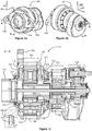
- Figures 1a and 1b show a gear system 101 according to an exemplifying and non-limiting embodiment.
- Figure 1c shows a section taken along polylines A-A shown in figures 1a and 1b .
- a part of the geometric section surface is parallel with the yz-plane of a coordinate system 199 and another part of the geometric section surface is parallel with the xz-plane of the coordinate system 199.
- the gear system 101 comprises a frame structure 102 that comprises connection sections 103 and 104 for attaching the frame structure 102 to a mechanical structure external to the gear system 101.
- the connection sections 103 and 104 prevent the frame structure 102 from rotating with respect to the external mechanical structure when the connection sections are attached to the external mechanical structure.
- the external mechanical structure can be for example a support structure in a nacelle of a wind power plant.
- the gear system 101 comprises a first planetary gear 105, a second planetary gear 119, and a cylindrical gear 123.
- a gear system according to an exemplifying and non-limiting embodiment comprises a planetary gear only, or only a cylindrical gear in addition to a planetary gear, or some other gear arrangement in addition to a planetary gear.
- the planetary gear 105 comprises a sun shaft 106 comprising a sun wheel 107.
- the sun shaft 106 is rotatable with respect to the frame structure 102.
- the planetary gear 105 comprises a gear ring 108 that is stationary with respect to the frame structure 102.
- the planetary gear 105 comprises a planet carrier 109 that comprises a mechanical interface structure 110 for connecting to a rotating element external to the gear system.
- the external rotating element can be for example a wind turbine.
- the planet carrier 109 is rotatably supported with respect to the frame structure 102 with the aid of first and second bearings 111 and 112, where the first bearing 111 is axially, i.e.
- the first and second bearings 111 and 112 are cylindrical roller bearings.
- the first bearing 111 can be some other bearing than a cylindrical roller bearing.
- the first bearing 111 can be a ball bearing or a plain bearing.
- the first bearing 111 is a tapered roller bearing and the axial clearance of the tapered roller bearing is adjusted with means for adjusting the axial position of the planet carrier 109, where the means are located between the planetary gears 105 and 119.
- the second bearing 112 can be some other bearing than a cylindrical roller bearing, e.g. a ball bearing, a plain bearing, or a tapered roller bearing.
- the first bearing 111 and the second bearing 112 can represent different bearing types. Thus, the invention is not limited to any specific bearing types.
- the planetary gear 105 comprises planet wheels supported rotatably with respect to the planet carrier 109 and meshing with the sun wheel 107 and with the gear ring 108.
- one of the planet wheels is denoted with a reference 113.
- the frame structure 102 comprises a front cover shield 114 that is a single piece of material such as e.g. steel or cast iron.
- the front cover shield 114 is attached to the gear ring 108, and the front cover shield 114 is shaped to constitute a bearing cover for covering and supporting the first bearing 111.
- the bearing cover covers the first bearing 111 so that the first bearing 111 is not seeable when the mechanical interface structure 110 of the planet carrier is viewed axially along the positive z-direction of the coordinate system 199.
- the diameter D1 of a portion of the planet carrier 109 being in contact with the first bearing 111 is greater than the diameter D2 of an aperture of the front cover shield 114 through which the mechanical interface structure 110 of the planet carrier is arranged to protrude.
- the front cover shield 114 is shaped to act as the bearing cover, there is no need for a separate bearing cover and therefore the number of components of the gear system as well as the number of assembly phases is reduced.
- the mechanical interface structure 110 of the planet carrier 109 and an end-section 115 of the planet carrier constitute a single piece of material.
- the end-section 115 supports first ends of planet wheel shafts of the planetary gear
- the planet carrier comprises another end-section that supports second ends pf the planet wheel shafts.
- the arrangement where the mechanical interface structure 110 and the end-section 115 constitute a single piece of material provides a compact and mechanically strong construction.
- the gear ring 108 of the planetary gear 105 constitutes a part of the frame structure 102 so that an outer surface of the gear ring 108 constitutes a part of an outer surface of the gear system 101. It is also possible that a frame structure of a gear system according to an exemplifying and non-limiting embodiment constitutes a housing so that a gear ring is inside the housing.
- Figure 1c shows a magnification of a part 118 of the section view of the gear system 101.
- the exemplifying gear system 101 comprises a seal 116 between the outer surface of the mechanical interface structure 110 and a wall of the aperture of the front cover shield 114 through which the mechanical interface structure 110 is arranged to protrude.
- the seal 116 can be for example a felt seal that is axially supported with a support plate 117. It is also possible that the seal 116 is a flinger ring seal.
- the second planetary gear 119 comprises a planet carrier 120 that is connected in a torque transferring way to the sun shaft 106 of the first planetary gear 105. Furthermore, the second planetary gear 119 comprises a gear ring 122, a sun shaft 125 comprising a sun wheel, and planet wheels rotatably supported with respect to the planet carrier 120 and meshing with the gear ring 122 and with the sun wheel of the second planetary gear 119.
- the frame structure 102 comprises an intermediate portion 121 connected to the gear ring 108 of the first planetary gear 105 and to the gear ring 122 of the second planetary gear 119.
- the gear ring 122 of the second planetary gear 119 constitutes a part of the frame structure 102 so that an outer surface of the gear ring 120 of the second planetary gear constitutes a part of the outer surface of the gear system 101.
- the cylindrical gear 123 comprises a first gear wheel 124 that is connected in a torque transferring way to the sun shaft 125 of the second planetary gear 119.
- the cylindrical gear 123 comprises a second gear wheel 126 that can be connected to a device external to the gear system 101.
- the external device can be for example a generator.
- the front cover shield 114 comprises the connection sections 103 and 104 for attaching the frame structure 102 to a mechanical structure external to the gear system 101.
- the connection sections 103 and 104 are radially protruding projections.
- the intermediate portion 121 comprises connection sections for attaching the frame structure 102 to a mechanical structure external to the gear system.
- An advantage related to the connection sections of the intermediate portion 121 is that these connection sections are, in the axial direction, near to the center of mass of the gear system. It is also possible that both the front cover shield 114 and the intermediate portion 121 comprise connection sections for attaching the frame structure 102 to a mechanical structure external to the gear system.
- FIG. 2 illustrates a wind power plant according to an exemplifying and non-limiting embodiment.
- the wind power plant comprises a wind rotor 250, a generator 252 for producing electric power, and a gear system 201 for transferring mechanical power from the wind rotor 250 to the generator 252.
- the gear system 201 can be for example such as the gear system 101 illustrated in figure 1a-1c .
- the wind rotor 250 is connected in a torque transferring way to the planet carrier of the first planetary gear of the gear system 201, and the frame structure of the gear system 201 is attached to support structures of a nacelle 251 of the wind power plant.
Landscapes
- Engineering & Computer Science (AREA)
- General Engineering & Computer Science (AREA)
- Mechanical Engineering (AREA)
- Life Sciences & Earth Sciences (AREA)
- Sustainable Development (AREA)
- Sustainable Energy (AREA)
- Chemical & Material Sciences (AREA)
- Combustion & Propulsion (AREA)
- Wind Motors (AREA)
- Retarders (AREA)
Abstract
Description
- The disclosure relates generally to gear systems. More particularly, the disclosure relates to a frame structure of a gear system comprising a planetary gear. Furthermore, the disclosure relates to a wind power plant comprising a gear system.
- In many power generating systems, it may be advantageous from the viewpoints of various design and constructional aspects to connect a generator to a prime mover, e.g. a wind turbine, via a gear system arranged to convert the rotational speed of the prime mover into a speed range suitable for the generator. For example, in a wind power plant, a gear system makes it possible to use a generator that is significantly smaller in dimensions and weight than a direct driven generator of a corresponding gearless wind power plant. Correspondingly, in many motor applications it may be advantageous to connect a motor to an actuator via a gear system arranged to convert the rotational speed of the motor into a speed range suitable for the actuator. The gear system may comprise a single gear stage or two or more series connected gear stages with the aid of which a desired gear-ratio is achieved. Each gear stage can be for example a planetary gear, a cylindrical gear, a bevel gear, or some other gear.
- Design aspects related to a gear system are, among others, the size and weight of the gear system and the number of components of the gear system. For example, in a wind power application, design aspects of the kind mentioned above must be optimized enough in order that a wind power plant with a gear system would be competitive with a gearless wind power plant having a direct driven generator. The choice whether to use a gear system or to have a gearless design depends on many different aspects many of which are in trade-off with each other. A gear system provides however many advantages and thus there is a need to provide technical solutions for alleviating or even eliminating the drawbacks related to the use of a gear system.
- The following presents a simplified summary in order to provide a basic understanding of some aspects of various invention embodiments. The summary is not an extensive overview of the invention. It is neither intended to identify key or critical elements of the invention nor to delineate the scope of the invention. The following summary merely presents some concepts of the invention in a simplified form as a prelude to a more detailed description of exemplifying embodiments of the invention.
- In this document, the word "geometric" when used as a prefix means a geometric concept that is not necessarily a part of any physical object. The geometric concept can be for example a geometric point, a straight or curved geometric line, a geometric plane, a non-planar geometric surface, a geometric space, or any other geometric entity that is zero, one, two, or three dimensional.
- In accordance with the invention, there is provided a new gear system that can be, for example but not necessarily, a gear system of a wind power plant.
- A gear system according to the invention comprises a frame structure comprising connection sections for attaching the frame structure to a mechanical structure external to the gear system, and a planetary gear comprising:
- a sun shaft comprising a sun wheel and being rotatable with respect to the frame structure,
- a gear ring stationary with respect to the frame structure,
- a planet carrier comprising a mechanical interface structure for connecting to a rotating element, e.g. a wind rotor, external to the gear system,
- first and second bearings supporting the planet carrier rotatably with respect to the frame structure, the first bearing being axially between the gear ring and the mechanical interface structure of the planet carrier, and
- planet wheels supported rotatably with respect to the planet carrier and meshing with the sun wheel and with the gear ring,
- The frame structure comprises a front cover shield that is a single piece of material, attached to the gear ring, and shaped to constitute a bearing cover for covering and supporting the above-mentioned first bearing, wherein the bearing cover covers the first bearing to be non-seeable when the mechanical interface structure of the planet carrier is viewed axially.
- As the front cover shield is shaped to act as a bearing cover, there is no need for a separate bearing cover and therefore the number of components of the gear system as well as the number of assembly phases is reduced.
- In accordance with the invention, there is provided also a new wind power plant that comprises:
- a wind rotor,
- a generator for producing electric power, and
- a gear system according to the invention for transferring mechanical power from the wind rotor to the generator.
- The above-mentioned wind rotor is connected in a torque transferring way to the planet carrier of the planetary gear of the gear system, and the frame structure of the gear system is attached to support structures of a nacelle of the wind power plant.
- Various exemplifying and non-limiting embodiments of the invention are described in accompanied dependent claims.
- Exemplifying and non-limiting embodiments of the invention both as to constructions and to methods of operation, together with additional objects and advantages thereof, will be best understood from the following description of specific exemplifying embodiments when read in conjunction with the accompanying drawings.
- The verbs "to comprise" and "to include" are used in this document as open limitations that neither exclude nor require the existence of also un-recited features. The features recited in the accompanied dependent claims are mutually freely combinable unless otherwise explicitly stated. Furthermore, it is to be understood that the use of "a" or "an", i.e. a singular form, throughout this document does not exclude a plurality.
- Exemplifying and non-limiting embodiments of the invention and their advantages are explained in greater detail below in the sense of examples and with reference to the accompanying drawings, in which:
-
figures 1a, 1b, and 1c illustrate a gear system according to an exemplifying and non-limiting embodiment, and -
figure 2 illustrates a wind power plant according to an exemplifying and non-limiting embodiment. - The specific examples provided in the description below should not be construed as limiting the scope and/or the applicability of the accompanied claims. Lists and groups of examples provided in the description are not exhaustive unless otherwise explicitly stated.
-
Figures 1a and 1b show agear system 101 according to an exemplifying and non-limiting embodiment.Figure 1c shows a section taken along polylines A-A shown infigures 1a and 1b . A part of the geometric section surface is parallel with the yz-plane of acoordinate system 199 and another part of the geometric section surface is parallel with the xz-plane of thecoordinate system 199. Thegear system 101 comprises aframe structure 102 that comprisesconnection sections frame structure 102 to a mechanical structure external to thegear system 101. Theconnection sections frame structure 102 from rotating with respect to the external mechanical structure when the connection sections are attached to the external mechanical structure. The external mechanical structure can be for example a support structure in a nacelle of a wind power plant. In the exemplifying case illustrated infigures 1a-1c , thegear system 101 comprises a firstplanetary gear 105, a secondplanetary gear 119, and acylindrical gear 123. - It is however also possible that a gear system according to an exemplifying and non-limiting embodiment comprises a planetary gear only, or only a cylindrical gear in addition to a planetary gear, or some other gear arrangement in addition to a planetary gear.
- The
planetary gear 105 comprises asun shaft 106 comprising asun wheel 107. Thesun shaft 106 is rotatable with respect to theframe structure 102. Theplanetary gear 105 comprises agear ring 108 that is stationary with respect to theframe structure 102. Theplanetary gear 105 comprises aplanet carrier 109 that comprises amechanical interface structure 110 for connecting to a rotating element external to the gear system. The external rotating element can be for example a wind turbine. Theplanet carrier 109 is rotatably supported with respect to theframe structure 102 with the aid of first andsecond bearings gear ring 108 and themechanical interface structure 110 of theplanet carrier 109 and the second bearing 112 is axially between the first and secondplanetary gears figures 1a-1c , the axial direction is parallel with the z-axis of thecoordinate system 199. In this exemplifying case, the first andsecond bearings first bearing 111 is a tapered roller bearing and the axial clearance of the tapered roller bearing is adjusted with means for adjusting the axial position of theplanet carrier 109, where the means are located between theplanetary gears second bearing 112 can be some other bearing than a cylindrical roller bearing, e.g. a ball bearing, a plain bearing, or a tapered roller bearing. Thefirst bearing 111 and thesecond bearing 112 can represent different bearing types. Thus, the invention is not limited to any specific bearing types. - The
planetary gear 105 comprises planet wheels supported rotatably with respect to theplanet carrier 109 and meshing with thesun wheel 107 and with thegear ring 108. Infigure 1c , one of the planet wheels is denoted with areference 113. Theframe structure 102 comprises afront cover shield 114 that is a single piece of material such as e.g. steel or cast iron. Thefront cover shield 114 is attached to thegear ring 108, and thefront cover shield 114 is shaped to constitute a bearing cover for covering and supporting thefirst bearing 111. The bearing cover covers thefirst bearing 111 so that thefirst bearing 111 is not seeable when themechanical interface structure 110 of the planet carrier is viewed axially along the positive z-direction of the coordinatesystem 199. As shown infigure 1c , the diameter D1 of a portion of theplanet carrier 109 being in contact with thefirst bearing 111 is greater than the diameter D2 of an aperture of thefront cover shield 114 through which themechanical interface structure 110 of the planet carrier is arranged to protrude. As thefront cover shield 114 is shaped to act as the bearing cover, there is no need for a separate bearing cover and therefore the number of components of the gear system as well as the number of assembly phases is reduced. - In the
exemplifying gear system 101 illustrated infigures 1a-1c , themechanical interface structure 110 of theplanet carrier 109 and an end-section 115 of the planet carrier constitute a single piece of material. The end-section 115 supports first ends of planet wheel shafts of the planetary gear, and the planet carrier comprises another end-section that supports second ends pf the planet wheel shafts. The arrangement where themechanical interface structure 110 and the end-section 115 constitute a single piece of material provides a compact and mechanically strong construction. - In the
exemplifying gear system 101 illustrated infigures 1a-1c , thegear ring 108 of theplanetary gear 105 constitutes a part of theframe structure 102 so that an outer surface of thegear ring 108 constitutes a part of an outer surface of thegear system 101. It is also possible that a frame structure of a gear system according to an exemplifying and non-limiting embodiment constitutes a housing so that a gear ring is inside the housing. -
Figure 1c shows a magnification of apart 118 of the section view of thegear system 101. Theexemplifying gear system 101 comprises aseal 116 between the outer surface of themechanical interface structure 110 and a wall of the aperture of thefront cover shield 114 through which themechanical interface structure 110 is arranged to protrude. Theseal 116 can be for example a felt seal that is axially supported with asupport plate 117. It is also possible that theseal 116 is a flinger ring seal. - The second
planetary gear 119 comprises aplanet carrier 120 that is connected in a torque transferring way to thesun shaft 106 of the firstplanetary gear 105. Furthermore, the secondplanetary gear 119 comprises agear ring 122, asun shaft 125 comprising a sun wheel, and planet wheels rotatably supported with respect to theplanet carrier 120 and meshing with thegear ring 122 and with the sun wheel of the secondplanetary gear 119. - In the
exemplifying gear system 101 illustrated infigures 1a-1c , theframe structure 102 comprises anintermediate portion 121 connected to thegear ring 108 of the firstplanetary gear 105 and to thegear ring 122 of the secondplanetary gear 119. Thegear ring 122 of the secondplanetary gear 119 constitutes a part of theframe structure 102 so that an outer surface of thegear ring 120 of the second planetary gear constitutes a part of the outer surface of thegear system 101. - The
cylindrical gear 123 comprises afirst gear wheel 124 that is connected in a torque transferring way to thesun shaft 125 of the secondplanetary gear 119. Thecylindrical gear 123 comprises asecond gear wheel 126 that can be connected to a device external to thegear system 101. The external device can be for example a generator. - In the
exemplifying gear system 101 illustrated infigures 1a-1c , thefront cover shield 114 comprises theconnection sections frame structure 102 to a mechanical structure external to thegear system 101. In this exemplifying case, theconnection sections intermediate portion 121 comprises connection sections for attaching theframe structure 102 to a mechanical structure external to the gear system. An advantage related to the connection sections of theintermediate portion 121 is that these connection sections are, in the axial direction, near to the center of mass of the gear system. It is also possible that both thefront cover shield 114 and theintermediate portion 121 comprise connection sections for attaching theframe structure 102 to a mechanical structure external to the gear system. -
Figure 2 illustrates a wind power plant according to an exemplifying and non-limiting embodiment. The wind power plant comprises awind rotor 250, agenerator 252 for producing electric power, and agear system 201 for transferring mechanical power from thewind rotor 250 to thegenerator 252. Thegear system 201 can be for example such as thegear system 101 illustrated infigure 1a-1c . Thewind rotor 250 is connected in a torque transferring way to the planet carrier of the first planetary gear of thegear system 201, and the frame structure of thegear system 201 is attached to support structures of anacelle 251 of the wind power plant. - The specific examples provided in the description given above should not be construed as limiting the scope and/or the applicability of the accompanied claims. Lists and groups of examples provided in the description given above are not exhaustive unless otherwise explicitly stated.
Claims (12)
- A gear system (101) comprising a frame structure (102) comprising connection sections (103, 104) for attaching the frame structure to a mechanical structure external to the gear system, and a first planetary gear (105) comprising:- a sun shaft (106) comprising a sun wheel (107) and being rotatable with respect to the frame structure,- a gear ring (108) stationary with respect to the frame structure,- a planet carrier (109) comprising a mechanical interface structure (110) for connecting to a rotating element external to the gear system,- first and second bearings (111, 112) supporting the planet carrier rotatably with respect to the frame structure, and- planet wheels (113) supported rotatably with respect to the planet carrier and meshing with the sun wheel and with the gear ring,wherein the first bearing is axially between the gear ring and the mechanical interface structure of the planet carrier, characterized in that the frame structure comprises a front cover shield (114) being a single piece of material, attached to the gear ring, and shaped to constitute a bearing cover for covering and supporting the first bearing (111), the bearing cover covering the first bearing to be non-seeable when the mechanical interface structure of the planet carrier is viewed axially.
- A gear system according to claim 1, wherein a diameter (D1) of a portion of the planet carrier being in contact with the first bearing is greater than a diameter (D2) of an aperture of the front cover shield through which the mechanical interface structure (110) of the planet carrier is arranged to protrude.
- A gear system according to claim 1 or 2, wherein the mechanical interface structure (110) of the planet carrier and an end-section (115) of the planet carrier constitute a single piece of material, the end-section of the planet carrier supporting first ends of planet wheel shafts of the planetary gear and another end-section of the planet carrier supporting second ends of the planet wheel shafts.
- A gear system according to any of claims 1-3, wherein the gear ring (108) of the first planetary gear constitutes a part of the frame structure so that an outer surface of the gear ring of the first planetary gear constitutes a part of an outer surface of the gear system.
- A gear system according to any of claims 1-4, wherein the front cover shield (114) comprises the connection sections (103, 104) of the frame structure.
- A gear system according to any of claims 1-5, wherein the gear system comprises a seal (116) between an outer surface of the mechanical interface structure of the planet carrier and a wall of an aperture of the front cover shield through which the mechanical interface structure of the planet carrier is arranged to protrude.
- A gear system according to any of claims 1-6, wherein the gear system comprises a second planetary gear (119) whose planet carrier (120) is connected in a torque transferring way to the sun shaft (106) of the first planetary gear.
- A gear system according to claim 7, wherein the frame structure comprises an intermediate portion (121) connected to the gear ring (108) of the first planetary gear and to a gear ring (122) of the second planetary gear.
- A gear system according to claim 8, wherein the gear ring of the second planetary gear constitutes a part of the frame structure so that an outer surface of the gear ring of the second planetary gear constitutes a part of an outer surface of the gear system.
- A gear system according to any of claims 7-9, wherein the gear system comprises a cylindrical gear (123) comprising first and second gear wheels (124, 126) meshing with each other, the first gear wheel (124) being connected in a torque transferring way to a sun shaft (125) of the second planetary gear.
- A gear system according to any of claims 1-10, wherein the first bearing (111) is one of the following: a cylindrical roller bearing, a ball bearing, a plain bearing, a tapered roller bearing.
- A wind power plant comprising:- a wind rotor (250),- a generator (252) for producing electric power, and- a gear system (201) according to any of claims 1-11 for transferring mechanical power from the wind rotor to the generator,wherein the wind rotor is connected in a torque transferring way to the planet carrier of the first planetary gear of the gear system, and the frame structure of the gear system is attached to support structures of a nacelle (251) of the wind power plant.
Priority Applications (9)
| Application Number | Priority Date | Filing Date | Title |
|---|---|---|---|
| ES19159712T ES2927327T3 (en) | 2019-02-27 | 2019-02-27 | gear system |
| PT191597129T PT3702647T (en) | 2019-02-27 | 2019-02-27 | A gear system |
| EP19159712.9A EP3702647B1 (en) | 2019-02-27 | 2019-02-27 | A gear system |
| DK19159712.9T DK3702647T3 (en) | 2019-02-27 | 2019-02-27 | A GEAR SYSTEM |
| BR102020003482-0A BR102020003482A2 (en) | 2019-02-27 | 2020-02-19 | GEAR SYSTEM |
| KR1020200021678A KR20200105413A (en) | 2019-02-27 | 2020-02-21 | A gear system |
| CN202010115026.6A CN111623087A (en) | 2019-02-27 | 2020-02-25 | Gear system |
| US16/801,436 US20200271100A1 (en) | 2019-02-27 | 2020-02-26 | Gear system |
| CA3073890A CA3073890A1 (en) | 2019-02-27 | 2020-02-27 | A gear system |
Applications Claiming Priority (1)
| Application Number | Priority Date | Filing Date | Title |
|---|---|---|---|
| EP19159712.9A EP3702647B1 (en) | 2019-02-27 | 2019-02-27 | A gear system |
Publications (2)
| Publication Number | Publication Date |
|---|---|
| EP3702647A1 true EP3702647A1 (en) | 2020-09-02 |
| EP3702647B1 EP3702647B1 (en) | 2022-08-24 |
Family
ID=65628670
Family Applications (1)
| Application Number | Title | Priority Date | Filing Date |
|---|---|---|---|
| EP19159712.9A Active EP3702647B1 (en) | 2019-02-27 | 2019-02-27 | A gear system |
Country Status (9)
| Country | Link |
|---|---|
| US (1) | US20200271100A1 (en) |
| EP (1) | EP3702647B1 (en) |
| KR (1) | KR20200105413A (en) |
| CN (1) | CN111623087A (en) |
| BR (1) | BR102020003482A2 (en) |
| CA (1) | CA3073890A1 (en) |
| DK (1) | DK3702647T3 (en) |
| ES (1) | ES2927327T3 (en) |
| PT (1) | PT3702647T (en) |
Cited By (1)
| Publication number | Priority date | Publication date | Assignee | Title |
|---|---|---|---|---|
| EP3992498A1 (en) * | 2020-10-29 | 2022-05-04 | Flender GmbH | Arrangement with a transmission and a working machine, method for simulation |
Families Citing this family (1)
| Publication number | Priority date | Publication date | Assignee | Title |
|---|---|---|---|---|
| EP4575269A1 (en) * | 2023-12-19 | 2025-06-25 | Flender GmbH | Planetary gear train having a sealed pitch tube |
Citations (5)
| Publication number | Priority date | Publication date | Assignee | Title |
|---|---|---|---|---|
| GB1232244A (en) * | 1967-08-11 | 1971-05-19 | ||
| WO1999025992A1 (en) * | 1996-05-21 | 1999-05-27 | Harmonic Drive Systems Inc. | Planetary gear device |
| CN202510680U (en) * | 2012-02-15 | 2012-10-31 | 三一电气有限责任公司 | Wind-power acceleration gearbox and mounting structure of hollow shaft thereof |
| US20130178326A1 (en) * | 2010-09-13 | 2013-07-11 | Repower Systems Se | Dismantling a gear mechanism of a wind power plant |
| EP2662598A1 (en) * | 2012-05-08 | 2013-11-13 | ZF Wind Power Antwerpen NV | Planetary gear stage with plain bearings as planet bearings |
Family Cites Families (4)
| Publication number | Priority date | Publication date | Assignee | Title |
|---|---|---|---|---|
| GB2473875A (en) * | 2009-09-28 | 2011-03-30 | Hansen Transmissions Int | Wind turbine gearbox with planetary gear unit having sliding bearings |
| EP2594789B1 (en) * | 2011-11-17 | 2014-04-30 | Siemens Aktiengesellschaft | Drive for a wind turbine |
| CN106949195A (en) * | 2017-05-09 | 2017-07-14 | 华东交通大学 | It is self-regulated to carry based on planet row and the uni-drive gear box carried coexists being linked between level |
| WO2019024043A1 (en) * | 2017-08-03 | 2019-02-07 | General Electric Company | Planet carrier of a wind turbine gearbox with improved lubricant path |
-
2019
- 2019-02-27 DK DK19159712.9T patent/DK3702647T3/en active
- 2019-02-27 PT PT191597129T patent/PT3702647T/en unknown
- 2019-02-27 ES ES19159712T patent/ES2927327T3/en active Active
- 2019-02-27 EP EP19159712.9A patent/EP3702647B1/en active Active
-
2020
- 2020-02-19 BR BR102020003482-0A patent/BR102020003482A2/en not_active Application Discontinuation
- 2020-02-21 KR KR1020200021678A patent/KR20200105413A/en not_active Withdrawn
- 2020-02-25 CN CN202010115026.6A patent/CN111623087A/en active Pending
- 2020-02-26 US US16/801,436 patent/US20200271100A1/en not_active Abandoned
- 2020-02-27 CA CA3073890A patent/CA3073890A1/en active Pending
Patent Citations (5)
| Publication number | Priority date | Publication date | Assignee | Title |
|---|---|---|---|---|
| GB1232244A (en) * | 1967-08-11 | 1971-05-19 | ||
| WO1999025992A1 (en) * | 1996-05-21 | 1999-05-27 | Harmonic Drive Systems Inc. | Planetary gear device |
| US20130178326A1 (en) * | 2010-09-13 | 2013-07-11 | Repower Systems Se | Dismantling a gear mechanism of a wind power plant |
| CN202510680U (en) * | 2012-02-15 | 2012-10-31 | 三一电气有限责任公司 | Wind-power acceleration gearbox and mounting structure of hollow shaft thereof |
| EP2662598A1 (en) * | 2012-05-08 | 2013-11-13 | ZF Wind Power Antwerpen NV | Planetary gear stage with plain bearings as planet bearings |
Cited By (2)
| Publication number | Priority date | Publication date | Assignee | Title |
|---|---|---|---|---|
| EP3992498A1 (en) * | 2020-10-29 | 2022-05-04 | Flender GmbH | Arrangement with a transmission and a working machine, method for simulation |
| WO2022090187A1 (en) | 2020-10-29 | 2022-05-05 | Flender Gmbh | Arrangement with a transmission and with a work machine, and simulation method |
Also Published As
| Publication number | Publication date |
|---|---|
| EP3702647B1 (en) | 2022-08-24 |
| DK3702647T3 (en) | 2022-10-24 |
| CN111623087A (en) | 2020-09-04 |
| PT3702647T (en) | 2022-09-14 |
| ES2927327T3 (en) | 2022-11-04 |
| BR102020003482A2 (en) | 2020-09-29 |
| US20200271100A1 (en) | 2020-08-27 |
| CA3073890A1 (en) | 2020-08-27 |
| KR20200105413A (en) | 2020-09-07 |
Similar Documents
| Publication | Publication Date | Title |
|---|---|---|
| US6921243B2 (en) | Device for producing electric current from wind energy | |
| EP1311759B1 (en) | Drive assembly for wind turbines | |
| US9279413B2 (en) | Wind turbine | |
| KR101890436B1 (en) | Gear box, seal, and cover arrangements | |
| EP1677005B1 (en) | Power generating wind turbine with a double-row tapered roller bearing | |
| CN111120583B (en) | Speed reducer and electromechanical device | |
| US9525320B2 (en) | Electromechanical device with included gear stages and internal lubrication system | |
| EP1836405B1 (en) | Bearing assembly for supporting a transmission shaft in a housing | |
| EP2339176A2 (en) | Wind turbine drivetrain system | |
| CA2739221C (en) | An electromechanical device | |
| CN102858459B (en) | Mill drive system | |
| US8647224B2 (en) | Generator arrangement for a wind power plant | |
| US20200271100A1 (en) | Gear system | |
| WO2014080327A2 (en) | Machine with two co-axial rotors | |
| CA2739229C (en) | An electromechanical device | |
| US20040213671A1 (en) | Drive assembly | |
| JP2020528514A (en) | Wind power generator | |
| HK40025727A (en) | A gear system | |
| HK40025727B (en) | A gear system | |
| EP2236823A1 (en) | Power transmission with high gear ratio, intended for a wind turbine | |
| EP1657437A1 (en) | Generator bearing arrangement in a wind power plant | |
| CN110999048A (en) | Generator for a wind energy installation and wind energy installation comprising a generator | |
| GB2499219A (en) | Vertical axis wind turbine with roof generator | |
| WO2015007338A1 (en) | A wind power generation assembly |
Legal Events
| Date | Code | Title | Description |
|---|---|---|---|
| PUAI | Public reference made under article 153(3) epc to a published international application that has entered the european phase |
Free format text: ORIGINAL CODE: 0009012 |
|
| STAA | Information on the status of an ep patent application or granted ep patent |
Free format text: STATUS: THE APPLICATION HAS BEEN PUBLISHED |
|
| AK | Designated contracting states |
Kind code of ref document: A1 Designated state(s): AL AT BE BG CH CY CZ DE DK EE ES FI FR GB GR HR HU IE IS IT LI LT LU LV MC MK MT NL NO PL PT RO RS SE SI SK SM TR |
|
| AX | Request for extension of the european patent |
Extension state: BA ME |
|
| REG | Reference to a national code |
Ref country code: HK Ref legal event code: DE Ref document number: 40025727 Country of ref document: HK |
|
| STAA | Information on the status of an ep patent application or granted ep patent |
Free format text: STATUS: REQUEST FOR EXAMINATION WAS MADE |
|
| 17P | Request for examination filed |
Effective date: 20210210 |
|
| RBV | Designated contracting states (corrected) |
Designated state(s): AL AT BE BG CH CY CZ DE DK EE ES FI FR GB GR HR HU IE IS IT LI LT LU LV MC MK MT NL NO PL PT RO RS SE SI SK SM TR |
|
| RIC1 | Information provided on ipc code assigned before grant |
Ipc: F03D 15/00 20160101ALN20220211BHEP Ipc: F16H 1/46 20060101ALN20220211BHEP Ipc: F16H 37/04 20060101ALN20220211BHEP Ipc: F16H 57/031 20120101ALI20220211BHEP Ipc: F16H 57/025 20120101AFI20220211BHEP |
|
| GRAP | Despatch of communication of intention to grant a patent |
Free format text: ORIGINAL CODE: EPIDOSNIGR1 |
|
| RIC1 | Information provided on ipc code assigned before grant |
Ipc: F16H 57/02 20120101ALN20220222BHEP Ipc: F03D 15/00 20160101ALN20220222BHEP Ipc: F16H 1/46 20060101ALN20220222BHEP Ipc: F16H 37/04 20060101ALN20220222BHEP Ipc: F16H 57/031 20120101ALI20220222BHEP Ipc: F16H 57/025 20120101AFI20220222BHEP |
|
| STAA | Information on the status of an ep patent application or granted ep patent |
Free format text: STATUS: GRANT OF PATENT IS INTENDED |
|
| INTG | Intention to grant announced |
Effective date: 20220331 |
|
| GRAS | Grant fee paid |
Free format text: ORIGINAL CODE: EPIDOSNIGR3 |
|
| GRAA | (expected) grant |
Free format text: ORIGINAL CODE: 0009210 |
|
| STAA | Information on the status of an ep patent application or granted ep patent |
Free format text: STATUS: THE PATENT HAS BEEN GRANTED |
|
| AK | Designated contracting states |
Kind code of ref document: B1 Designated state(s): AL AT BE BG CH CY CZ DE DK EE ES FI FR GB GR HR HU IE IS IT LI LT LU LV MC MK MT NL NO PL PT RO RS SE SI SK SM TR |
|
| REG | Reference to a national code |
Ref country code: CH Ref legal event code: EP |
|
| REG | Reference to a national code |
Ref country code: FI Ref legal event code: FGE |
|
| REG | Reference to a national code |
Ref country code: PT Ref legal event code: SC4A Ref document number: 3702647 Country of ref document: PT Date of ref document: 20220914 Kind code of ref document: T Free format text: AVAILABILITY OF NATIONAL TRANSLATION Effective date: 20220908 Ref country code: IE Ref legal event code: FG4D |
|
| REG | Reference to a national code |
Ref country code: AT Ref legal event code: REF Ref document number: 1513866 Country of ref document: AT Kind code of ref document: T Effective date: 20220915 Ref country code: DE Ref legal event code: R096 Ref document number: 602019018532 Country of ref document: DE |
|
| REG | Reference to a national code |
Ref country code: DK Ref legal event code: T3 Effective date: 20221019 |
|
| REG | Reference to a national code |
Ref country code: ES Ref legal event code: FG2A Ref document number: 2927327 Country of ref document: ES Kind code of ref document: T3 Effective date: 20221104 |
|
| REG | Reference to a national code |
Ref country code: LT Ref legal event code: MG9D |
|
| REG | Reference to a national code |
Ref country code: NL Ref legal event code: MP Effective date: 20220824 |
|
| PG25 | Lapsed in a contracting state [announced via postgrant information from national office to epo] |
Ref country code: SE Free format text: LAPSE BECAUSE OF FAILURE TO SUBMIT A TRANSLATION OF THE DESCRIPTION OR TO PAY THE FEE WITHIN THE PRESCRIBED TIME-LIMIT Effective date: 20220824 Ref country code: RS Free format text: LAPSE BECAUSE OF FAILURE TO SUBMIT A TRANSLATION OF THE DESCRIPTION OR TO PAY THE FEE WITHIN THE PRESCRIBED TIME-LIMIT Effective date: 20220824 Ref country code: NO Free format text: LAPSE BECAUSE OF FAILURE TO SUBMIT A TRANSLATION OF THE DESCRIPTION OR TO PAY THE FEE WITHIN THE PRESCRIBED TIME-LIMIT Effective date: 20221124 Ref country code: NL Free format text: LAPSE BECAUSE OF FAILURE TO SUBMIT A TRANSLATION OF THE DESCRIPTION OR TO PAY THE FEE WITHIN THE PRESCRIBED TIME-LIMIT Effective date: 20220824 Ref country code: LV Free format text: LAPSE BECAUSE OF FAILURE TO SUBMIT A TRANSLATION OF THE DESCRIPTION OR TO PAY THE FEE WITHIN THE PRESCRIBED TIME-LIMIT Effective date: 20220824 Ref country code: LT Free format text: LAPSE BECAUSE OF FAILURE TO SUBMIT A TRANSLATION OF THE DESCRIPTION OR TO PAY THE FEE WITHIN THE PRESCRIBED TIME-LIMIT Effective date: 20220824 |
|
| REG | Reference to a national code |
Ref country code: AT Ref legal event code: MK05 Ref document number: 1513866 Country of ref document: AT Kind code of ref document: T Effective date: 20220824 |
|
| PG25 | Lapsed in a contracting state [announced via postgrant information from national office to epo] |
Ref country code: PL Free format text: LAPSE BECAUSE OF FAILURE TO SUBMIT A TRANSLATION OF THE DESCRIPTION OR TO PAY THE FEE WITHIN THE PRESCRIBED TIME-LIMIT Effective date: 20220824 Ref country code: IS Free format text: LAPSE BECAUSE OF FAILURE TO SUBMIT A TRANSLATION OF THE DESCRIPTION OR TO PAY THE FEE WITHIN THE PRESCRIBED TIME-LIMIT Effective date: 20221224 Ref country code: HR Free format text: LAPSE BECAUSE OF FAILURE TO SUBMIT A TRANSLATION OF THE DESCRIPTION OR TO PAY THE FEE WITHIN THE PRESCRIBED TIME-LIMIT Effective date: 20220824 Ref country code: GR Free format text: LAPSE BECAUSE OF FAILURE TO SUBMIT A TRANSLATION OF THE DESCRIPTION OR TO PAY THE FEE WITHIN THE PRESCRIBED TIME-LIMIT Effective date: 20221125 |
|
| PG25 | Lapsed in a contracting state [announced via postgrant information from national office to epo] |
Ref country code: SM Free format text: LAPSE BECAUSE OF FAILURE TO SUBMIT A TRANSLATION OF THE DESCRIPTION OR TO PAY THE FEE WITHIN THE PRESCRIBED TIME-LIMIT Effective date: 20220824 Ref country code: RO Free format text: LAPSE BECAUSE OF FAILURE TO SUBMIT A TRANSLATION OF THE DESCRIPTION OR TO PAY THE FEE WITHIN THE PRESCRIBED TIME-LIMIT Effective date: 20220824 Ref country code: CZ Free format text: LAPSE BECAUSE OF FAILURE TO SUBMIT A TRANSLATION OF THE DESCRIPTION OR TO PAY THE FEE WITHIN THE PRESCRIBED TIME-LIMIT Effective date: 20220824 Ref country code: AT Free format text: LAPSE BECAUSE OF FAILURE TO SUBMIT A TRANSLATION OF THE DESCRIPTION OR TO PAY THE FEE WITHIN THE PRESCRIBED TIME-LIMIT Effective date: 20220824 |
|
| PGFP | Annual fee paid to national office [announced via postgrant information from national office to epo] |
Ref country code: FR Payment date: 20230221 Year of fee payment: 5 Ref country code: FI Payment date: 20230224 Year of fee payment: 5 |
|
| REG | Reference to a national code |
Ref country code: DE Ref legal event code: R097 Ref document number: 602019018532 Country of ref document: DE |
|
| PG25 | Lapsed in a contracting state [announced via postgrant information from national office to epo] |
Ref country code: SK Free format text: LAPSE BECAUSE OF FAILURE TO SUBMIT A TRANSLATION OF THE DESCRIPTION OR TO PAY THE FEE WITHIN THE PRESCRIBED TIME-LIMIT Effective date: 20220824 Ref country code: EE Free format text: LAPSE BECAUSE OF FAILURE TO SUBMIT A TRANSLATION OF THE DESCRIPTION OR TO PAY THE FEE WITHIN THE PRESCRIBED TIME-LIMIT Effective date: 20220824 |
|
| PGFP | Annual fee paid to national office [announced via postgrant information from national office to epo] |
Ref country code: GB Payment date: 20230221 Year of fee payment: 5 |
|
| PG25 | Lapsed in a contracting state [announced via postgrant information from national office to epo] |
Ref country code: AL Free format text: LAPSE BECAUSE OF FAILURE TO SUBMIT A TRANSLATION OF THE DESCRIPTION OR TO PAY THE FEE WITHIN THE PRESCRIBED TIME-LIMIT Effective date: 20220824 |
|
| PLBE | No opposition filed within time limit |
Free format text: ORIGINAL CODE: 0009261 |
|
| STAA | Information on the status of an ep patent application or granted ep patent |
Free format text: STATUS: NO OPPOSITION FILED WITHIN TIME LIMIT |
|
| 26N | No opposition filed |
Effective date: 20230525 |
|
| PG25 | Lapsed in a contracting state [announced via postgrant information from national office to epo] |
Ref country code: SI Free format text: LAPSE BECAUSE OF FAILURE TO SUBMIT A TRANSLATION OF THE DESCRIPTION OR TO PAY THE FEE WITHIN THE PRESCRIBED TIME-LIMIT Effective date: 20220824 |
|
| REG | Reference to a national code |
Ref country code: DK Ref legal event code: EBP Effective date: 20230228 |
|
| PG25 | Lapsed in a contracting state [announced via postgrant information from national office to epo] |
Ref country code: MC Free format text: LAPSE BECAUSE OF FAILURE TO SUBMIT A TRANSLATION OF THE DESCRIPTION OR TO PAY THE FEE WITHIN THE PRESCRIBED TIME-LIMIT Effective date: 20220824 |
|
| REG | Reference to a national code |
Ref country code: CH Ref legal event code: PL |
|
| PG25 | Lapsed in a contracting state [announced via postgrant information from national office to epo] |
Ref country code: LU Free format text: LAPSE BECAUSE OF NON-PAYMENT OF DUE FEES Effective date: 20230227 Ref country code: LI Free format text: LAPSE BECAUSE OF NON-PAYMENT OF DUE FEES Effective date: 20230228 Ref country code: CH Free format text: LAPSE BECAUSE OF NON-PAYMENT OF DUE FEES Effective date: 20230228 |
|
| REG | Reference to a national code |
Ref country code: IE Ref legal event code: MM4A |
|
| PG25 | Lapsed in a contracting state [announced via postgrant information from national office to epo] |
Ref country code: PT Free format text: LAPSE BECAUSE OF NON-PAYMENT OF DUE FEES Effective date: 20231129 Ref country code: IE Free format text: LAPSE BECAUSE OF NON-PAYMENT OF DUE FEES Effective date: 20230227 Ref country code: DK Free format text: LAPSE BECAUSE OF NON-PAYMENT OF DUE FEES Effective date: 20230228 |
|
| PG25 | Lapsed in a contracting state [announced via postgrant information from national office to epo] |
Ref country code: IT Free format text: LAPSE BECAUSE OF FAILURE TO SUBMIT A TRANSLATION OF THE DESCRIPTION OR TO PAY THE FEE WITHIN THE PRESCRIBED TIME-LIMIT Effective date: 20220824 |
|
| REG | Reference to a national code |
Ref country code: DE Ref legal event code: R081 Ref document number: 602019018532 Country of ref document: DE Owner name: FLENDER GMBH, DE Free format text: FORMER OWNER: MOVENTAS GEARS OY, JYVAESKYLAE, FI |
|
| PG25 | Lapsed in a contracting state [announced via postgrant information from national office to epo] |
Ref country code: FI Free format text: LAPSE BECAUSE OF NON-PAYMENT OF DUE FEES Effective date: 20240227 |
|
| GBPC | Gb: european patent ceased through non-payment of renewal fee |
Effective date: 20240227 |
|
| PG25 | Lapsed in a contracting state [announced via postgrant information from national office to epo] |
Ref country code: FI Free format text: LAPSE BECAUSE OF NON-PAYMENT OF DUE FEES Effective date: 20240227 |
|
| PG25 | Lapsed in a contracting state [announced via postgrant information from national office to epo] |
Ref country code: BG Free format text: LAPSE BECAUSE OF FAILURE TO SUBMIT A TRANSLATION OF THE DESCRIPTION OR TO PAY THE FEE WITHIN THE PRESCRIBED TIME-LIMIT Effective date: 20220824 |
|
| PG25 | Lapsed in a contracting state [announced via postgrant information from national office to epo] |
Ref country code: BG Free format text: LAPSE BECAUSE OF FAILURE TO SUBMIT A TRANSLATION OF THE DESCRIPTION OR TO PAY THE FEE WITHIN THE PRESCRIBED TIME-LIMIT Effective date: 20220824 |
|
| PG25 | Lapsed in a contracting state [announced via postgrant information from national office to epo] |
Ref country code: GB Free format text: LAPSE BECAUSE OF NON-PAYMENT OF DUE FEES Effective date: 20240227 |
|
| PG25 | Lapsed in a contracting state [announced via postgrant information from national office to epo] |
Ref country code: FR Free format text: LAPSE BECAUSE OF NON-PAYMENT OF DUE FEES Effective date: 20240229 |
|
| PG25 | Lapsed in a contracting state [announced via postgrant information from national office to epo] |
Ref country code: GB Free format text: LAPSE BECAUSE OF NON-PAYMENT OF DUE FEES Effective date: 20240227 Ref country code: FR Free format text: LAPSE BECAUSE OF NON-PAYMENT OF DUE FEES Effective date: 20240229 |
|
| PGFP | Annual fee paid to national office [announced via postgrant information from national office to epo] |
Ref country code: DE Payment date: 20250226 Year of fee payment: 7 |
|
| PGFP | Annual fee paid to national office [announced via postgrant information from national office to epo] |
Ref country code: BE Payment date: 20250218 Year of fee payment: 7 |
|
| PGFP | Annual fee paid to national office [announced via postgrant information from national office to epo] |
Ref country code: ES Payment date: 20250331 Year of fee payment: 7 |
|
| PG25 | Lapsed in a contracting state [announced via postgrant information from national office to epo] |
Ref country code: CY Free format text: LAPSE BECAUSE OF FAILURE TO SUBMIT A TRANSLATION OF THE DESCRIPTION OR TO PAY THE FEE WITHIN THE PRESCRIBED TIME-LIMIT; INVALID AB INITIO Effective date: 20190227 |
|
| PG25 | Lapsed in a contracting state [announced via postgrant information from national office to epo] |
Ref country code: HU Free format text: LAPSE BECAUSE OF FAILURE TO SUBMIT A TRANSLATION OF THE DESCRIPTION OR TO PAY THE FEE WITHIN THE PRESCRIBED TIME-LIMIT; INVALID AB INITIO Effective date: 20190227 |