EP4236288A1 - Information processing apparatus, method for controlling information processing apparatus, computer program and computer-readable data carrier - Google Patents
Information processing apparatus, method for controlling information processing apparatus, computer program and computer-readable data carrier Download PDFInfo
- Publication number
- EP4236288A1 EP4236288A1 EP23156400.6A EP23156400A EP4236288A1 EP 4236288 A1 EP4236288 A1 EP 4236288A1 EP 23156400 A EP23156400 A EP 23156400A EP 4236288 A1 EP4236288 A1 EP 4236288A1
- Authority
- EP
- European Patent Office
- Prior art keywords
- color
- measurement
- job
- verification
- chart
- Prior art date
- Legal status (The legal status is an assumption and is not a legal conclusion. Google has not performed a legal analysis and makes no representation as to the accuracy of the status listed.)
- Pending
Links
Images


Classifications
-
- H—ELECTRICITY
- H04—ELECTRIC COMMUNICATION TECHNIQUE
- H04N—PICTORIAL COMMUNICATION, e.g. TELEVISION
- H04N1/00—Scanning, transmission or reproduction of documents or the like, e.g. facsimile transmission; Details thereof
- H04N1/46—Colour picture communication systems
- H04N1/56—Processing of colour picture signals
- H04N1/60—Colour correction or control
- H04N1/603—Colour correction or control controlled by characteristics of the picture signal generator or the picture reproducer
- H04N1/6033—Colour correction or control controlled by characteristics of the picture signal generator or the picture reproducer using test pattern analysis
- H04N1/6044—Colour correction or control controlled by characteristics of the picture signal generator or the picture reproducer using test pattern analysis involving a sensor integrated in the machine or otherwise specifically adapted to read the test pattern
-
- G—PHYSICS
- G06—COMPUTING OR CALCULATING; COUNTING
- G06F—ELECTRIC DIGITAL DATA PROCESSING
- G06F3/00—Input arrangements for transferring data to be processed into a form capable of being handled by the computer; Output arrangements for transferring data from processing unit to output unit, e.g. interface arrangements
- G06F3/12—Digital output to print unit, e.g. line printer, chain printer
- G06F3/1201—Dedicated interfaces to print systems
- G06F3/1202—Dedicated interfaces to print systems specifically adapted to achieve a particular effect
- G06F3/1203—Improving or facilitating administration, e.g. print management
- G06F3/1208—Improving or facilitating administration, e.g. print management resulting in improved quality of the output result, e.g. print layout, colours, workflows, print preview
-
- G—PHYSICS
- G06—COMPUTING OR CALCULATING; COUNTING
- G06F—ELECTRIC DIGITAL DATA PROCESSING
- G06F3/00—Input arrangements for transferring data to be processed into a form capable of being handled by the computer; Output arrangements for transferring data from processing unit to output unit, e.g. interface arrangements
- G06F3/12—Digital output to print unit, e.g. line printer, chain printer
- G06F3/1201—Dedicated interfaces to print systems
- G06F3/1202—Dedicated interfaces to print systems specifically adapted to achieve a particular effect
- G06F3/121—Facilitating exception or error detection and recovery, e.g. fault, media or consumables depleted
-
- G—PHYSICS
- G06—COMPUTING OR CALCULATING; COUNTING
- G06F—ELECTRIC DIGITAL DATA PROCESSING
- G06F3/00—Input arrangements for transferring data to be processed into a form capable of being handled by the computer; Output arrangements for transferring data from processing unit to output unit, e.g. interface arrangements
- G06F3/12—Digital output to print unit, e.g. line printer, chain printer
- G06F3/1201—Dedicated interfaces to print systems
- G06F3/1202—Dedicated interfaces to print systems specifically adapted to achieve a particular effect
- G06F3/1211—Improving printing performance
- G06F3/1215—Improving printing performance achieving increased printing speed, i.e. reducing the time between printing start and printing end
-
- G—PHYSICS
- G06—COMPUTING OR CALCULATING; COUNTING
- G06F—ELECTRIC DIGITAL DATA PROCESSING
- G06F3/00—Input arrangements for transferring data to be processed into a form capable of being handled by the computer; Output arrangements for transferring data from processing unit to output unit, e.g. interface arrangements
- G06F3/12—Digital output to print unit, e.g. line printer, chain printer
- G06F3/1201—Dedicated interfaces to print systems
- G06F3/1223—Dedicated interfaces to print systems specifically adapted to use a particular technique
- G06F3/1237—Print job management
- G06F3/1244—Job translation or job parsing, e.g. page banding
-
- G—PHYSICS
- G06—COMPUTING OR CALCULATING; COUNTING
- G06F—ELECTRIC DIGITAL DATA PROCESSING
- G06F3/00—Input arrangements for transferring data to be processed into a form capable of being handled by the computer; Output arrangements for transferring data from processing unit to output unit, e.g. interface arrangements
- G06F3/12—Digital output to print unit, e.g. line printer, chain printer
- G06F3/1201—Dedicated interfaces to print systems
- G06F3/1223—Dedicated interfaces to print systems specifically adapted to use a particular technique
- G06F3/1237—Print job management
- G06F3/1253—Configuration of print job parameters, e.g. using UI at the client
- G06F3/1256—User feedback, e.g. print preview, test print, proofing, pre-flight checks
-
- G—PHYSICS
- G06—COMPUTING OR CALCULATING; COUNTING
- G06F—ELECTRIC DIGITAL DATA PROCESSING
- G06F3/00—Input arrangements for transferring data to be processed into a form capable of being handled by the computer; Output arrangements for transferring data from processing unit to output unit, e.g. interface arrangements
- G06F3/12—Digital output to print unit, e.g. line printer, chain printer
- G06F3/1201—Dedicated interfaces to print systems
- G06F3/1223—Dedicated interfaces to print systems specifically adapted to use a particular technique
- G06F3/1237—Print job management
- G06F3/1259—Print job monitoring, e.g. job status
-
- H—ELECTRICITY
- H04—ELECTRIC COMMUNICATION TECHNIQUE
- H04N—PICTORIAL COMMUNICATION, e.g. TELEVISION
- H04N1/00—Scanning, transmission or reproduction of documents or the like, e.g. facsimile transmission; Details thereof
- H04N1/32—Circuits or arrangements for control or supervision between transmitter and receiver or between image input and image output device, e.g. between a still-image camera and its memory or between a still-image camera and a printer device
- H04N1/32101—Display, printing, storage or transmission of additional information, e.g. ID code, date and time or title
- H04N1/32128—Display, printing, storage or transmission of additional information, e.g. ID code, date and time or title attached to the image data, e.g. file header, transmitted message header, information on the same page or in the same computer file as the image
- H04N1/32133—Display, printing, storage or transmission of additional information, e.g. ID code, date and time or title attached to the image data, e.g. file header, transmitted message header, information on the same page or in the same computer file as the image on the same paper sheet, e.g. a facsimile page header
-
- H—ELECTRICITY
- H04—ELECTRIC COMMUNICATION TECHNIQUE
- H04N—PICTORIAL COMMUNICATION, e.g. TELEVISION
- H04N2201/00—Indexing scheme relating to scanning, transmission or reproduction of documents or the like, and to details thereof
- H04N2201/32—Circuits or arrangements for control or supervision between transmitter and receiver or between image input and image output device, e.g. between a still-image camera and its memory or between a still-image camera and a printer device
- H04N2201/3201—Display, printing, storage or transmission of additional information, e.g. ID code, date and time or title
- H04N2201/3269—Display, printing, storage or transmission of additional information, e.g. ID code, date and time or title of machine readable codes or marks, e.g. bar codes or glyphs
-
- Y—GENERAL TAGGING OF NEW TECHNOLOGICAL DEVELOPMENTS; GENERAL TAGGING OF CROSS-SECTIONAL TECHNOLOGIES SPANNING OVER SEVERAL SECTIONS OF THE IPC; TECHNICAL SUBJECTS COVERED BY FORMER USPC CROSS-REFERENCE ART COLLECTIONS [XRACs] AND DIGESTS
- Y02—TECHNOLOGIES OR APPLICATIONS FOR MITIGATION OR ADAPTATION AGAINST CLIMATE CHANGE
- Y02P—CLIMATE CHANGE MITIGATION TECHNOLOGIES IN THE PRODUCTION OR PROCESSING OF GOODS
- Y02P90/00—Enabling technologies with a potential contribution to greenhouse gas [GHG] emissions mitigation
- Y02P90/30—Computing systems specially adapted for manufacturing
Definitions
- the present invention relates to an information processing apparatus, to a method for controlling the information processing apparatus, to a computer program and to a computer-readable data carrier having stored thereon the said program.
- color management is performed on a regular basis to secure a predetermined color reproducibility.
- the color management is performed by comparing a target color defined by a standard such as International Organization for Standardization (ISO) standards and a color (printed color) actually printed by a printer, and checking whether the color precision satisfies an acceptance criterion.
- ISO International Organization for Standardization
- regeneration of a print profile and correction processing using a color correction function of the printer are necessary, which takes time and labor.
- Japanese Patent Application Laid-Open Publication No. 2020-30754 discusses a technique of performing verification of the color precision (color verification) of a printer at a plurality of timings during printing, determining a correction operation execution period based on the verification results, and displaying a history of the verification results.
- a chart in which color patches each corresponding to a target color are arranged is printed using a printer, and color values corresponding to the respective color patches are measured using a measuring device. Further, in a case where a plurality of colors is verified at a time, a plurality of charts is printed by a printer and the plurality of charts is set on a measuring device and measured. At this time, if the plurality of different charts is set and measured by the measuring device in random order, there is a possibility that a color verification may be performed using an inappropriate chart.
- Japanese Patent Application Laid-Open Publication No. 2020-30754 discusses no processing regarding the foregoing possibility.
- an information processing apparatus as specified in claims 1 to 12.
- a method for controlling an information processing apparatus as specified in claim 13.
- a computer program as specified in claim 14.
- a computer-readable data carrier having stored thereon the said computer program, as specified in claim 15.
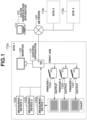
- Fig. 1 is a diagram schematically illustrating an overall configuration of a color verification system according to a first embodiment.
- a predetermined chart is printed out from a target printer.
- a color measurement of color patches on the printed chart is performed, and the obtained colorimetric data is transmitted to a color verification apparatus 100.
- the color verification apparatus 100 checks a difference between a printed color and a target color (color precision).
- color patches arranged on the chart are also referred to as a color chart or a color sample, and are simply referred to as "patches" in this specification.
- the color verification apparatus 100 and sites 1 to 3 (170a to 170c) are connected via a network 160.
- the site 1 includes a control apparatus 110, a monitor 120, printers 1 to 3 (130a to 130c), and measuring devices 1 to 3 (150a to 150c).
- each of the site 2 and the site 3 also includes a control apparatus, a monitor, printers, and measuring devices.
- a relationship between the site 1 and the color verification apparatus 100 will be described as an example.
- the color verification apparatus 100 compares a color serving as a target color defined in advance (target color) and a color actually printed by a printer (printed color), to verify whether the color precision of the printed color satisfies an acceptance criterion.
- the color verification apparatus 100 is connected to the control apparatus 110 via the network 160 to be communicable with each other.
- the control apparatus 110 is connected to the printers 130a to 130c in the site 1 via a communication network such as an intranet to be communicable with each other, and issues a print instruction to each printer and centrally manages the color precision of each printer. Further, regarding the print instruction, for example, the control apparatus 110 can divide a print job received from a client terminal (not illustrated) into predetermined units (e.g., units of copies or units of pages) so that separate print instructions for one print job are issued dispersedly to a plurality of printers.
- predetermined units e.g., units of copies or units of pages
- a print job includes a page description language (PDL) data portion for describing, on a page unit basis, a rendering command for an object with an attribute such as a text, a graphic, and a picture, and print setting information for designating a sheet size and a sheet type, and print conditions such as a double-sided/single-sided printing.
- PDL page description language
- the monitor 120 is connected to the control apparatus 110, and displays various kinds of user interface (UI) screens.
- UI user interface
- Each of the printers 1 to 3 (130a to 130c) prints a color image on a sheet based on a print job from the control apparatus 110 using, for example, an electrophotographic process technique.
- Each of the printers 1 to 3 may be a monochrome printer or a printer using another image forming technique, such as an ink-jet printer. Further, each of the printers 1 to 3 may be a multifunction peripheral having a copy function or a facsimile (FAX) function in addition to the print function.
- FAX facsimile
- Each of the measuring devices 1 to 3 is a spectrophotometric measuring device for measuring a color value of a target object based on a reflectance ratio or a transmission ratio of visible light with a wavelength of about 400 nm to 700 nm.
- the measuring devices 1 to 3 are prepared for each of the sites 1 to 3 to obtain colorimetric data by converting the wavelengths obtained for patches of charts printed out by the printers 1 to 3 into values in, for example, an L*a*b* color space or an XYZ color space.
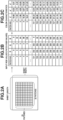
- Fig. 2A is an example of the chart
- Fig. 2B illustrates target color values (RGB values) for the patches (patch numbers 1 to 729) of the chart defined in the RGB color space.
- Each of the measuring devices 1 to 3 is a measuring device including a line sensor or an area sensor for scanning the chart.
- the measuring device is an automatic document reading type measuring device using a sheet-through method
- the measuring device can measure the color after detecting a position of each patch to be measured by pre-scanning the chart using a built-in line sensor.
- the measuring device can automatically feed sheets and perform continuous measuring, the measuring device can measure the color of each patch in a similar manner after detecting the position of each patch by pre-scanning the chart with a built-in area sensor.
- a portable (hand-held) type measuring device can also be used, but in this case, a scanner for scanning the chart additionally needs to be connected to the control apparatus 110.
- the measuring device is connected to the control apparatus 110 via, for example, a universal serial bus (USB), and measures a color value of each patch on the chart printed out from a target printer to obtain colorimetric data illustrated in Fig. 2C .
- the obtained colorimetric data is transmitted to the color verification apparatus 100 via the control apparatus 110.
- the color verification apparatus 100 is installed in one of the sites 1 to 3, the color verification apparatus 100 and the measuring device may be connected directly, so that the color verification apparatus 100 can obtain the colorimetric data from the measuring device without the control apparatus 110.
- the network 160 is, for example, a local area network (LAN), the Internet, or an intranet, and may be a wireless or wired network.
- LAN local area network
- the Internet the Internet
- intranet an intranet
- Each of the sites 1 to 3 (170a to 170c) corresponds to a location of a printing company where the printers are installed.
- the site 1 is a printing site in Tokyo
- the site 2 is a printing site in Osaka
- the site 3 is a printing site in Fukuoka.
- the configuration of the color verification system illustrated in Fig. 1 is just an example, and the number of sites or the configuration of each apparatus in each of the sites can be changed as appropriate.
- the color verification apparatus 100 may be directly connected to the control apparatus 110 or to the measuring devices 1 to 3 via a communication network such as an intranet to manage color precision of each of the plurality of printers 1 to 3.
- a communication network such as an intranet to manage color precision of each of the plurality of printers 1 to 3.
- an information processing apparatus including both functions of the color verification apparatus 100 and the control apparatus 110 may be provided in each site, and the information processing apparatus may manage the color precision of the plurality of printers in the site.
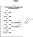
- Fig. 3 is a block diagram illustrating a hardware configuration of the color verification apparatus 100 and the control apparatus 110, and each of the color verification apparatus 100 and the control apparatus 110 includes a central processing unit (CPU) 101, a read-only memory (ROM) 102, a random access memory (RAM) 103, a hard disk drive (HDD) 104, a display unit 105, an operation unit 106, a network interface (I/F) 107, and an external apparatus I/F 108.
- the components 101 to 108 illustrated in Fig. 3 are connected to each other via a system bus 109.
- the CPU 101 is an arithmetic processing unit for controlling the entire apparatus and performs image processing to be described below, based on a program stored in the ROM 102.
- the ROM 102 is a read only memory storing, for example, a boot program, a processing program, character data, and character code information.
- the RAM 103 is a random access memory used as a work memory when the CPU 101 executes various programs. Further, the RAM 103 is used as a data storage area for storing image files received via the network I/F 107.
- the HDD 104 is used for storing, for example, results of the arithmetic processing executed by the CPU 101, various kinds of programs, and various kinds of information files.
- the display unit 105 is configured of, for example, a liquid crystal display and displays a user interface screen for making various settings or checking an apparatus state.
- the operation unit 106 is configured of a keyboard or buttons and used by a user to input or reset various kinds of setting values.
- the network I/F 107 is an interface for connecting the apparatus to the network 160.
- the color verification apparatus 100 and the control apparatus 110 can exchange various kinds of information with external apparatuses via the network I/F 107.
- the external apparatus I/F 108 is an interface for connecting to the external apparatuses such as the measuring devices 1 to 3 via a communication bus, for example, a USB bus.
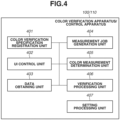
- FIG. 4 is a block diagram illustrating a main functional configuration of the color verification apparatus 100 and the control apparatus 110 according to the present embodiment.
- Each of the color verification apparatus 100 and the control apparatus 110 includes a color verification specification registration unit 401, a UI control unit 402, a data obtaining unit 403, a measurement job generation unit 404, a color measurement determination unit 405, a verification processing unit 406, and a setting processing unit 407.
- These functional units are implemented by the CPU 101 executing a predetermined program.
- each functional unit will be described.
- the color verification specification registration unit 401 registers, for each type of color verification, a chart on which patches of various colors corresponding to target color values are arranged, a printer to be subjected to the color verification, a measuring device used for color verification, and an allowable value set for the color verification. More specifically, the chart to be registered is stored in the HDD 104 in a state where information about the chart indicating a chart configuration such as the number of patches and the sizes of the patches in the chart (chart configuration information) is associated with the image data.
- the charts are roughly classified into a predefined chart defined according to a standard such as International Standard Organization (ISO) standards, and a custom chart uniquely defined by a user.
- the predefined chart is stored in advance, for example, when a color verification program is installed.
- the custom chart is registered at any timing based on the user's input via the operation unit 106.
- the printer to be subjected to the color verification is registered from among the printers 130a, 130b, and 130c connected to the control apparatus 110.
- the measuring device to be used for the color verification is registered from among the measuring devices 150a, 150b, and 150c.
- the allowable value at a time of the color verification is a value used when a color to be a target (target color) determined based on a standard such as ISO standards, and a color (printed color) actually printed by the printer are compared to check whether the color precision satisfies the acceptance criterion.
- a color difference value is registered as an allowable value, and if the color difference value is the allowable value or less, the color precision is determined to satisfy the acceptance criterion.
- a user selects a color verification specification from among the color verification specifications registered with the color verification specification registration unit 401, and the measurement job generation unit 404 generates a measurement job. Then, the color verification is started.
- the UI control unit 402 performs control to display a user interface screen for a user to check a state of each apparatus in the color verification system, to input or select various setting values, and to issue a start instruction for each of various kinds of processing.
- the user interface screen to be displayed will be described below.
- the data obtaining unit 403 obtains various kinds of information and data used by the color measurement determination unit 405 or the verification processing unit 406, to be described below.
- the user selects a plurality of color verification specifications used for the color verifications from among the verification specifications registered by the user with the color verification specification registration unit 401, and the measurement job generation unit 404 generates measurement jobs.
- the color measurement determination unit 405 determines whether each of the measurement target charts corresponds to one of the measurement jobs.
- a bar code with a measurement job identifier (ID) embedded therein is provided to the chart, and the color measurement determination unit 405 determines whether the measurement target chart is a chart corresponding to the measurement job based on the bar code information.
- the verification processing unit 406 performs verification processing to determine whether the color precision of the target printer satisfies the acceptance criterion using the colorimetric data received from the measuring device.
- the setting processing unit 407 performs settings of various parameters relating to the verification processing based on the user's selection or the like via a predetermined user interface screen.
- Fig. 5 is a sequence diagram illustrating a flow of processing in the color verification system according to the present embodiment.
- the flow of processing in the overall verification system will be described with reference to the sequence diagram illustrated in Fig. 5 using, as an example, a case where a plurality of color verifications for the printer 1 is performed using the measuring device 1 by outputting a plurality of charts.
- the symbol "S" means a step.
- step S501 the color verification specification registration unit 401 starts a color verification specification registration, based on a user's input.
- a color verification specification registration button 601 on a main menu screen illustrated in Fig. 6A
- the screen shifts to a color verification specification registration screen illustrated in Fig. 6B .
- These UI screens are controlled by the UI control unit 402.
- the user inputs a name of the custom chart to be registered, the number of patches, patch sizes, a sheet size/type, and then uploads image data.
- the chart image is generated in a file format such as Tag Image File Format (TIFF), Portable Document Format (PDF), and Joint Photographic Experts Group (JPEG) format.
- TIFF Tag Image File Format
- PDF Portable Document Format
- JPEG Joint Photographic Experts Group
- the chart is registered in a display area 613 or 614 indicative of "unregistered" of the chart selection screen in Fig. 6D .
- a registered chart list and chart configuration information for each chart are collectively referred to as "chart information”.
- the data obtaining unit 403 obtains a list of the printers 1 to 3 managed by the control apparatus 110, and information indicating a status of each printer (hereinbelow, referred to as "printer status information").
- the printer status information includes information about, for example, a power status (ON/OFF), presence or absence of a malfunction, and a processing status (printing/standby) of a print job.
- the control apparatus 110 periodically accesses each of the printers 1 to 3 to obtain the printer status information and hold the information therein.
- the printer list and the printer status information for each printer are collectively referred to as "printer information”.
- step S503 the color verification specification registration unit 401 receives a press of "select printer” in a display area 608 on the color verification specification detail selection screen in Fig. 6C . Then, the screen shifts to a printer selection screen in Fig. 6E , and processing for receiving selection of a printer to be a target of the color verification (hereinbelow, referred to as a "target printer") is performed. More specifically, the UI control unit 402 receives a user's selection via the UI screen displayed on the display unit 105, and the setting processing unit 407 sets the selected printer (printer 1 in this case) as the target printer.
- Fig. 6E illustrates a printer selection screen used when the user selects a target printer.
- printers that can be processing targets are listed and displayed according to the printer information obtained in step S502.
- display processing of, for example, greying out the printers in a print disabled condition is performed based on the printer status information so that it is recognizable whether each printer is in a print enabled condition or a print disabled condition.
- the printer selection screen in Fig. 6E only the printer 2 is grayed out to indicate that the printer 2 is in a print disabled condition.
- the data obtaining unit 403 obtains a list of the measuring devices 1 to 3 managed by the control apparatus 110, and specification information of each measuring device, and information indicating a status of each measuring device (hereinbelow, referred to as "measuring device status information").
- the specification information is information indicating the specification of each measuring device, such as a processable sheet size, a processable minimum patch size, and the minimum/maximum number of patches for one sheet (one page). If the measuring device has an accessory added thereto, the specification information includes information about a specification difference depending on whether the accessory is attached to the measuring device.
- the accessory means a measurement ruler, an automatic sheet feeding unit, or the like.
- the measurement ruler is a device for assisting a hand-held type measuring device in a slide operation at a time of measurement to enable a stable color measurement.
- a sensor mounted on the back side of the measuring device detects a stripe pattern of the measurement ruler to enable detection of a measurement direction (left to right, or right to left) in which the user is performing the measurement.
- the automatic sheet feeding unit is a device that automatically takes charts printed by and output from the printer into the measuring device to enable a continuous color measurement.
- the measuring device status information includes information such as a power status (ON/OFF) and a connection status.
- the control apparatus 110 preliminarily or periodically accesses the measuring devices 1 to 3 to obtain the specification information and the measuring device status information, and holds the pieces of information therein.
- the measuring device list, and the specification information and the measuring device status information for each measuring device are collectively referred to as "measuring device information".
- step S505 the color verification specification registration unit 401 receives a press of "select measuring device" in a display area 609 on the color verification specification detail selection screen in Fig. 6C . Then, the screen shifts to a measuring device selection screen illustrated in Fig. 6F , and processing for receiving selection of a measuring device used for measuring a chart color value is performed. More specifically, the UI control unit 402 receives a user's selection via the UI screen displayed on the display unit 105, and the setting processing unit 407 sets the selected measuring device as a measuring device used for the chart measurement. Fig. 6F illustrates the measuring device selection screen used by the user to select a measuring device.
- measuring devices that can be a processing target are listed according to the measuring device information obtained in step S504.
- display processing of, for example, greying out the measuring device in an unusable condition is performed based on the measuring device status information so that it is recognizable whether the measuring device is in a usable condition or an unusable condition.
- the measuring device selection screen in Fig. 6F only the measuring device 2 is greyed out to indicate that the measuring device 2 is in an unusable condition.
- step S506 the color verification specification registration unit 401 receives a press of "input allowable value" in a display area 610 on the color verification specification detail selection screen in Fig. 6C . Then, the screen shifts to an allowable value input screen illustrated in Fig. 6G , and processing for accepting data such as a target color value for each patch in the used chart, and an allowable value for each verification item is performed. More specifically, the UI control unit 402 receives user's inputs via the UI screen displayed on the display unit 105, and the setting processing unit 407 sets the input target color value and the input allowable value for each verification item.
- Fig. 6G illustrates the allowable value input screen used by the user to input the allowable values of the verification items.
- Fig. 6G illustrates the allowable value input screen for setting an allowable value corresponding to each verification item.
- the user sets the allowable value corresponding to each verification item in advance via such a UI screen.
- the color difference ⁇ E is a rectilinear distance between a target color value and a color value (color measurement value) indicated by the measured data in an L*a*b* color space, and can be obtained using, for example, the following equation (1).
- an allowable value of a color difference for each verification item is set as displayed on the allowable value input screen in Fig. 6G .
- the color verification is determined as "passed” (OK). If any of the verification items exceeds the allowable value, the color verification is determined as "failed” (NG).
- step S507 the measurement job generation unit 404 starts the color verification, based on a user's input.
- a color verification button 602 on the main menu screen illustrated in Fig. 6A the screen shifts to a color verification specification selection screen illustrated in Fig. 6H .
- These UI screens are controlled by the UI control unit 402.
- step S508 if the user presses either of "color verification specification 1" in a display area 625 and "color verification specification 2" in a display area 626 on the color verification specification selection screen in Fig. 6H , the measurement job generation unit 404 performs processing of generating a measurement job corresponding to the selected color verification specification. In addition, it is possible to generate a plurality of measurement jobs by selecting a plurality of color verification specifications at a time. When a measurement job is generated, the target printer of the color verification, the measuring device to be used, and the chart and the allowable values used for the color verification, which are registered in the processing in steps S501 to S506, are uniquely determined.
- a measurement job ID (job identifier) is assigned to the image data of the chart.
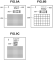
- a chart illustrated in Fig. 9A is a color chart with a measurement job ID assigned thereto.
- a page number 901 indicates a page number of the color chart, and in a case where the color chart used for the color verification consists of a plurality of pages, the page number 901 is counted up.
- a display ID 902 is a display ID for a measurement job ID, and an ID code associated with each measurement job is assigned thereto. Checking the display ID enables the user to recognize the color chart associated with the measurement job.
- a detail ID 903 is an ID for details of the measurement job ID and used in measurement determination processing performed in step S515 (described below) to automatically determine which measurement job the chart corresponds to.
- the detail ID 903 is an example of a detail ID for the case of a one-dimensional bar code that is a one-dimensional code.
- Table 1 illustrates a format example of the one-dimensional bar code.
- the one-dimensional bar code includes chart layout information in the first to the eighth digits, and in a case of a number "RRCCXXYY", the "RR" indicates the number of rows, the "CC” indicates the number of columns, the "XX” indicates a patch size in the horizontal direction, and the "YY” indicates a patch size in the vertical direction.
- the number in the 9th digit indicates a chart page number, and the numbers in the 11th to 46th digits indicate numbers associated with the measurement job ID.
- the numbers in the 48th to 51st digits indicate a check sum, which is used to distinguish the bar code from other bar codes in order to prevent tampering.
- Table 1 illustrates the numbers corresponding to the respective digits in the regular expression.
- Table 1 Digit Content Format (Regular Expression) 1-8 Chart Layout Information [0-9A-F] 9 Page Number [0-9] 10 Blank Blank 11-46 Measurement Job ID Number [0-9A-F] ⁇ 8 ⁇ -[0-9A-F] ⁇ 4 ⁇ -[0-9A-F] ⁇ 4 ⁇ -[0-9A-F] ⁇ 4 ⁇ -[0-9A-F] ⁇ 12 ⁇ 47 Blank ⁇ * 48-51 Check Sum ⁇ d ⁇ 4 ⁇
- a measurement job ID including copy number information may be assigned to each copy of the chart to enable the user to determine which printed copy of the chart it is.
- Using the measurement job ID in the Table 2 enables the measured value of the second copy of the chart to be sent to the color verification apparatus 100.
- Color patches 904 are arranged on a chart, and the color verification is performed by performing the color measurement of the patches.
- the charts with different numbers assigned thereto as the measurement job IDs illustrated in Figs. 9A and 9B are used when a plurality of color verifications is performed.
- the display IDs 902 and 906 are display IDs of the measurement job IDs, and ID codes associated with the respective measurement jobs are assigned thereto, so that display IDs 902 and 906 are assigned the different display IDs. Checking the display ID enables the user to recognize by which of the printer 1 and the printer 2 the chart is printed out.
- the detail IDs 903 and 907 are detail IDs of the measurement IDs, and are assigned different ID codes associated with the respective measurement jobs. Thus, the detail IDs 903 and 907 are different.
- the color patches 904 and the color patches 908 consist of patches based on different signal values.
- a detail ID 909 in Fig. 9C is an ID for details to be used in measurement determination processing in step S515 described below.
- the detail ID 909 is an example of a detail ID in the form of a QR code ® that is a two-dimensional code.
- the sensor built in the measuring device used to pre-scan the chart can be a line sensor (liner sensor) to read bar codes. In this case, a bar code is assigned to the chart.
- the sensor built in the measuring device is an area sensor in which a plurality of elements is arranged two-dimensionally in horizontal and vertical directions
- a QR code is assigned to the chart because more information can be embedded in a QR code than a bar code.
- a chart with the measurement job IDs two types of IDs: display ID and detail ID assigned thereto is provided to the target printer.
- the image data of the determined chart is transmitted to the control apparatus 110 via the network I/F 107.
- step S509 the control apparatus 110 transmits the print jobs for the plurality of charts to the target printer, based on the received image data.
- step S510 the target printer that has received the print jobs performs print processing to output the plurality of charts based on the print jobs.
- step S511 the control apparatus 110 performs processing to prompt the user to perform color measurement of the plurality of charts printed out from the target printer. More specifically, the control apparatus 110 displays a chart measurement screen (guidance screen) as illustrated in Fig. 6J to prompt the user to set the plurality of printed out charts on the measuring device.
- a chart measurement screen guidance screen
- step S512 the control apparatus 110 instructs the selected measuring device (measuring device 1 in this case) to pre-scan the plurality of charts printed out from the target printer.
- step S513 the selected measuring device performs pre-scanning of the plurality of charts.
- step S514 the selected measuring device transmits pieces of image data corresponding to the plurality of charts obtained by the pre-scanning to the control apparatus 110.
- step S515 upon receiving the pre-scanned images, the color measurement determination unit 405 performs processing to determine whether the measurement target charts set on the measuring device in step S511 are the charts corresponding to the measurement jobs generated in step S508. Details of this measurement determination processing will be described below.
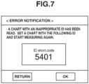
- step S5166 the UI control unit 402 displays an error notification on the display unit 105.
- Fig. 7 illustrates an error notification screen that displays the error notification.
- the UI control unit 402 displays a correct ID on the display unit 105 as illustrated in Fig. 7 to prompt the user to start a measurement again.
- step S517 the control apparatus 110 instructs to perform color measurement of the plurality of charts printed out from the target printer.
- step S5108 when the user sets the plurality of charts and issues an instruction to start measurement, the selected measuring device (measuring device 1 in this case) measures a color value of each patch on the chart.
- step S519 after completing the measurement, the selected measuring device stores sets of pieces of obtained colorimetric data and the measurement job IDs as data, and transmits the sets of data to the control apparatus 110.
- step S520 the control apparatus 110 receives the sets of data each including the colorimetric data and the measurement job ID from the selected measuring device, and transfers the sets of data to the color verification apparatus 100.
- step S521 the verification processing unit 406 performs processing to verify the color precision of the printer associated with the corresponding measurement job ID using the sets of data. In a case where the data includes a plurality of measurement job IDs, the verification processing unit 406 performs color verification processing for each of the measurement job IDs.
- step S522 the UI control unit 402 displays a verification result on the display unit 105.
- Fig. 6I illustrates a report result screen displaying the verification result.
- the result of "passed/failed" (OK/NG) for each verification item is displayed together with the average value of the color differences, the maximum value of the color differences, and the color differences for the respective primary colors (CMYK) for each patch.
- CMSYK primary colors
- control apparatus 110 may issue a preparation instruction to the selected measuring device to execute calibration before starting the measurement.
- step S515 the color measurement determination processing performed in step S515 will be described in detail with reference to a flowchart illustrated in Fig. 8 .
- a series of the processing in the flowchart in Fig. 8 is implemented by the CPU 101 of the color verification apparatus 100 loading a corresponding program to the color measurement determination unit 405, and executing the program.
- the symbol "S" means a step.
- step S801 the color measurement determination unit 405 obtains the pre-scanned image data transmitted from the selected measuring device in step S514.
- step S802 the color measurement determination unit 405 determines whether the image data obtained by pre-scanning the chart in step S801 includes a bar code. More specifically, the color measurement determination unit 405 performs binarization processing on the image data, performs labeling processing by sequentially scanning the image data, and detects an area between the black bars on the both right and left sides of the bar code (whole). Next, the color measurement determination unit 405 counts the number of white areas in the whole area, and if the number of white areas is a predetermined number, the color measurement determination unit 405 determines that the image data includes the bar code label (YES in step S802), and the processing proceeds to step S803.
- the color measurement determination unit 405 determines that the image data includes no bar code label (NO in step S802), and the processing proceeds to step S517.
- the bar code determination method is not limited to the method according to the present embodiment, and a known technique can be used.
- step S803 the color measurement determination unit 405 determines a code system of the bar code in the area determined to be a bar code label in step S802, and obtains bar code data illustrated in Table 1 by decoding the bar code.
- step S804 the color measurement determination unit 405 determines whether the measurement job ID number corresponding to the 11th to 46th digits in the bar code data (see Table 1) obtained in step S803 coincides with any one of the plurality of measurement job IDs generated in step S508. If the color measurement determination unit 405 determines that the measurement job ID number coincides with any one of the plurality of measurement job IDs generated in step S508 (YES in step S804), the processing proceeds to step S517. On the other hand, if the color measurement determination unit 405 determines that the measurement job ID number does not coincide with any one of the plurality of measurement job IDs generated in step S508 (NO in step S804), the processing proceeds to step S516.
- the plurality of measurement jobs is generated at a time, and the plurality of printed charts is subjected to the color measurement all at a time. At this time, it is automatically determined which one of the measurement jobs each one of the plurality of charts corresponds to using the measurement job IDs, and the color verification is performed by applying the measurement value to the corresponding measurement job. In this way, since the color measurement operation can be performed on the plurality of color verifications on the same printer at a time, convenience for users is improved.
- the plurality of measurement jobs is generated at a time, and the plurality of printed charts is subjected to the color measurement all at a time. In this case, it is automatically determined which one of the measurement jobs each one of the plurality of charts corresponds to using the measurement job IDs, and the color verification is performed by applying the measurement value to the corresponding measurement job.
- a plurality of color verifications is desired to be performed at a time on a plurality of different printers.
- a description will be given of a configuration in which, in a case where a plurality of color verifications is performed at a time on a plurality of different printers, a color verification for each printer is performed by applying a color measurement value to a corresponding measurement job.
- a description of the basic configuration of the color verification system common to the first embodiment will be omitted.
- a schematic diagram illustrating an entire configuration of the color verification system according to the second embodiment is similar to that of the first embodiment, and thus a description thereof is omitted.
- a block diagram illustrating a hardware configuration of the color verification apparatus 100 and the control apparatus 110 according to the second embodiment is similar to that according to the first embodiment, and thus a description thereof is omitted.
- a block diagram illustrating a main functional configuration of the color verification apparatus 100 and the control apparatus 110 according to the second embodiment is similar to that according to the first embodiment, and thus a description thereof is omitted.
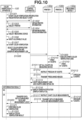
- Fig. 10 is a sequence diagram illustrating a flow of processing in the color verification system according to the present embodiment.
- a description will be given of a flow of processing in the entire color verification system according to the present embodiment centering on portions different from the first embodiment, with reference to the sequence diagram in Fig. 10 .
- Processing from the start of the color verification specification registration in step S1001 to the start of the color verification in S1007 is the same as the processing from the start of the color verification specification registration in step S501 to the start of the color verification in step S507 in the sequence diagram in Fig. 5 according to the first embodiment, and thus a description thereof is omitted.
- step S1008 when a user presses either of "color verification specification 1" in the display area 625 and "color verification specification 2" in the display area 626 on the color verification specification selection screen in Fig. 6H , the measurement job generation unit 404 performs processing for generating a measurement job corresponding to each color verification specification.
- printers each to be a target of the color verification, a measuring device to be used, and charts and allowable values used for the color verification, which are registered in the processing performed in steps S 1001 to S 1006, are uniquely determined.
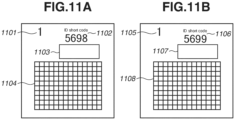
- the charts are similar, as illustrated in Figs. 11A and 11B , different measurement job IDs are assigned to the respective charts. More specifically, a chart illustrated in Fig. 11A is output to the printer 1, and a chart illustrated in Fig. 11B is output to the printer 2.
- the same number is assigned to chart page numbers 1101 and 1105.
- color patches 1104 and color patches 1108 are respectively formed based on the same signal values.
- display IDs 1102 and 1106 are display IDs of the measurement job IDs, and ID codes associated with the respective measurement jobs are assigned thereto, so that the display IDs 1102 and 1106 are different. Checking the display IDs enables the user to recognize by which of the printer 1 and the printer 2 the chart is printed out.
- detail IDs 1103 and 1107 are detail IDs of the measurement IDs, and are assigned different ID codes associated with the respective measurement jobs. Thus, the detail IDs 1103 and 1107 are different. Then, the detail IDs are used when it is desired to automatically determine to which measurement job a chart corresponds (which printer has printed the chart) in measurement determination processing in step S1015 to be described below.
- step S1009 based on the received image data, the control apparatus 110 transmits the print job of the chart illustrated in Fig. 11A to the printer 1, and transmits the print job of the chart illustrated in Fig. 11B to the printer 2.
- step S1010 the printer 1 that has received the print job performs print processing based on the print job to output the chart illustrated in Fig. 11A .
- the printer 2 that has received the print job performs print processing based on the print job to output the chart illustrated in Fig. 11B .
- step S1011 the control apparatus 110 performs processing to prompt the user to collectively perform color measurement on the plurality of charts printed out from the printer 1 and the printer 2 illustrated in Figs. 11A and 11B . More specifically, the control apparatus 110 displays the chart measurement (guidance) screen as illustrated in Fig. 6J , to prompt the user to set the plurality of printed out charts on the measuring device.
- step S1012 the control apparatus 110 issues an instruction to the selected measuring device (measuring device 1 in this case) to pre-scan the plurality of charts output from the printer 1 and the printer 2 illustrated in Figs. 11A and 11B .
- step S1013 the selected measuring device performs a pre-scan of the plurality of charts illustrated in Figs. 11A and 11B .
- step S1014 after completing the pre-scan, the selected measuring device transmits the obtained pieces of image data from the plurality of charts illustrated in Figs. 11A and 11B to the control apparatus 110.
- step S1015 upon receiving the pre-scanned images, the color measurement determination unit 405 performs processing to determine whether the measurement target charts set on the measuring device in step S1011 are the charts corresponding to the measurement jobs generated in step S 1008.
- This measurement determination processing is similar to that performed in the first embodiment, and thus a description thereof will be omitted.
- step S1016 the UI control unit 402 displays an error notification on the display unit 105.
- step S1017 the control apparatus 110 performs color measurement on the plurality of charts printed out from the printer 1 and the printer 2 illustrated in Figs. 11A and 11B .
- Processing from the chart measurement in step S1018 to the display of the color verification result in step S1022 is the same as that from step S518 to step S522 in Fig. 5 of the first embodiment, and thus descriptions thereof are omitted.
- a plurality of measurement jobs is generated at a time, and a plurality of printed charts printed by the different printers is collectively subjected to color measurement.
- step S1015 it is automatically determined with which of the plurality of measurement job IDs the measurement job ID number corresponding to the 11th to 46th digits of the bar code data obtained from the chart coincides (i.e., from which printer the chart is output). In this way, a plurality of color verifications can be performed for different printers in one color measurement operation, thereby improving convenience for users.
- a plurality of color verifications can be performed at a time in one color measurement operation, and thus convenience for users can be improved.
- Embodiment(s) of the present invention can also be realized by a computer of a system or apparatus that reads out and executes computer executable instructions (e.g., one or more programs) recorded on a storage medium (which may also be referred to more fully as a 'non-transitory computer-readable storage medium') to perform the functions of one or more of the above-described embodiment(s) and/or that includes one or more circuits (e.g., application specific integrated circuit (ASIC)) for performing the functions of one or more of the above-described embodiment(s), and by a method performed by the computer of the system or apparatus by, for example, reading out and executing the computer executable instructions from the storage medium to perform the functions of one or more of the above-described embodiment(s) and/or controlling the one or more circuits to perform the functions of one or more of the above-described embodiment(s).
- computer executable instructions e.g., one or more programs
- a storage medium which may also be referred to more fully as
- the computer may comprise one or more processors (e.g., central processing unit (CPU), micro processing unit (MPU)) and may include a network of separate computers or separate processors to read out and execute the computer executable instructions.
- the computer executable instructions may be provided to the computer, for example, from a network or the storage medium.
- the storage medium may include, for example, one or more of a hard disk, a random-access memory (RAM), a read only memory (ROM), a storage of distributed computing systems, an optical disk (such as a compact disc (CD), digital versatile disc (DVD), or Blu-ray Disc (BD) TM ), a flash memory device, a memory card, and the like.
Landscapes
- Engineering & Computer Science (AREA)
- Theoretical Computer Science (AREA)
- General Engineering & Computer Science (AREA)
- Human Computer Interaction (AREA)
- Physics & Mathematics (AREA)
- General Physics & Mathematics (AREA)
- Multimedia (AREA)
- Signal Processing (AREA)
- Quality & Reliability (AREA)
- Accessory Devices And Overall Control Thereof (AREA)
- Color Image Communication Systems (AREA)
- Spectrometry And Color Measurement (AREA)
Applications Claiming Priority (1)
| Application Number | Priority Date | Filing Date | Title |
|---|---|---|---|
| JP2022026375A JP2023122718A (ja) | 2022-02-24 | 2022-02-24 | 情報処理装置、その制御方法及びプログラム |
Publications (1)
| Publication Number | Publication Date |
|---|---|
| EP4236288A1 true EP4236288A1 (en) | 2023-08-30 |
Family
ID=85227101
Family Applications (1)
| Application Number | Title | Priority Date | Filing Date |
|---|---|---|---|
| EP23156400.6A Pending EP4236288A1 (en) | 2022-02-24 | 2023-02-13 | Information processing apparatus, method for controlling information processing apparatus, computer program and computer-readable data carrier |
Country Status (4)
| Country | Link |
|---|---|
| US (1) | US12363244B2 (enExample) |
| EP (1) | EP4236288A1 (enExample) |
| JP (1) | JP2023122718A (enExample) |
| CN (1) | CN116643708A (enExample) |
Families Citing this family (1)
| Publication number | Priority date | Publication date | Assignee | Title |
|---|---|---|---|---|
| JP2024033661A (ja) * | 2022-08-31 | 2024-03-13 | セイコーエプソン株式会社 | 情報処理装置、情報処理方法および情報処理システム |
Citations (2)
| Publication number | Priority date | Publication date | Assignee | Title |
|---|---|---|---|---|
| JP2020030754A (ja) | 2018-08-24 | 2020-02-27 | コニカミノルタ株式会社 | 色精度検証装置、色精度検証方法及びプログラム |
| EP3667428A1 (en) * | 2018-12-11 | 2020-06-17 | Canon Kabushiki Kaisha | Management system, information processing apparatus, control method therefor, and storage medium |
Family Cites Families (11)
| Publication number | Priority date | Publication date | Assignee | Title |
|---|---|---|---|---|
| WO1999010866A1 (en) * | 1997-08-25 | 1999-03-04 | Imagicolor Corp | A system for distributing and controlling color reproduction at multiple sites |
| JP2007104218A (ja) * | 2005-10-03 | 2007-04-19 | Canon Inc | 情報処理装置及びその制御方法、プログラム |
| KR101618857B1 (ko) * | 2014-07-10 | 2016-05-10 | 성낙철 | 웹페이지 인쇄문서 검증 시스템 |
| US9778635B2 (en) * | 2015-01-20 | 2017-10-03 | Lenovo Enterprise Solutions (Singapore) Pte. Ltd. | Executing an additive manufacturing job by a plurality of additive manufacturing printers |
| JP6160933B2 (ja) * | 2015-04-13 | 2017-07-12 | コニカミノルタ株式会社 | 色管理装置及びチャート利用制御方法並びにチャート利用制御プログラム |
| JP7158155B2 (ja) * | 2018-02-20 | 2022-10-21 | キヤノン株式会社 | 情報処理装置とその制御方法、及びプログラム |
| JP7057682B2 (ja) * | 2018-02-21 | 2022-04-20 | キヤノン株式会社 | 色管理システム、印刷装置とその制御方法、及びプログラム |
| JP2020153829A (ja) * | 2019-03-20 | 2020-09-24 | 株式会社リコー | 画像形成情報取得方法、プロファイル作成システム及びカラーチャート |
| US11705226B2 (en) * | 2019-09-19 | 2023-07-18 | Tempus Labs, Inc. | Data based cancer research and treatment systems and methods |
| JP7414604B2 (ja) * | 2020-03-19 | 2024-01-16 | キヤノン株式会社 | 印刷システム |
| JP2024503509A (ja) * | 2021-01-19 | 2024-01-25 | シーエイチエス ヘルスケア ベンチャーズ インコーポレイテッド | 医療用注入ラインを認証するためのシステムおよび方法 |
-
2022
- 2022-02-24 JP JP2022026375A patent/JP2023122718A/ja active Pending
-
2023
- 2023-02-13 EP EP23156400.6A patent/EP4236288A1/en active Pending
- 2023-02-16 US US18/170,434 patent/US12363244B2/en active Active
- 2023-02-23 CN CN202310161688.0A patent/CN116643708A/zh active Pending
Patent Citations (2)
| Publication number | Priority date | Publication date | Assignee | Title |
|---|---|---|---|---|
| JP2020030754A (ja) | 2018-08-24 | 2020-02-27 | コニカミノルタ株式会社 | 色精度検証装置、色精度検証方法及びプログラム |
| EP3667428A1 (en) * | 2018-12-11 | 2020-06-17 | Canon Kabushiki Kaisha | Management system, information processing apparatus, control method therefor, and storage medium |
Non-Patent Citations (2)
| Title |
|---|
| ANONYMOUS: "Removable media job setup for document copier", RESEARCH DISCLOSURE, KENNETH MASON PUBLICATIONS, HAMPSHIRE, UK, GB, vol. 318, no. 11, 1 October 1990 (1990-10-01), XP007115612, ISSN: 0374-4353 * |
| WU WENCHENG ET AL: "Optimal patch code design via device characterization", IMAGE QUALITY AND SYSTEM PERFORMANCE IX, SPIE, 1000 20TH ST. BELLINGHAM WA 98225-6705 USA, vol. 8293, no. 1, 22 January 2012 (2012-01-22), pages 1 - 9, XP060000947, DOI: 10.1117/12.905668 * |
Also Published As
| Publication number | Publication date |
|---|---|
| US12363244B2 (en) | 2025-07-15 |
| JP2023122718A (ja) | 2023-09-05 |
| CN116643708A (zh) | 2023-08-25 |
| US20230269343A1 (en) | 2023-08-24 |
Similar Documents
| Publication | Publication Date | Title |
|---|---|---|
| US9560228B2 (en) | Document reading apparatus, control method in document reading apparatus, and storage medium | |
| US9766847B1 (en) | Management of an image forming apparatus using test page data | |
| US20190349488A1 (en) | Image processor and program | |
| US8760675B2 (en) | Image reading apparatus and image reading system having a reading preference input operation | |
| US20240402965A1 (en) | Image processing apparatus, method for controlling the same, and storage medium | |
| US20210081149A1 (en) | Printing apparatus and method for controlling the same | |
| EP4236288A1 (en) | Information processing apparatus, method for controlling information processing apparatus, computer program and computer-readable data carrier | |
| US11899989B2 (en) | Information processing apparatus, image forming system, information processing method, and non-transitory recording medium for monitoring color matching processing | |
| JP5644751B2 (ja) | 画像形成装置、及び画像形成装置の制御プログラム | |
| US10983741B2 (en) | Image processing apparatuses and an external server configured in a case image information in an unsupported format is not supported, controls so as to perform conversion of the unsupported format | |
| EP4124009B1 (en) | Information processing apparatus, control method thereof, program, and storage medium | |
| US20240328859A1 (en) | Information processing apparatus, and method for controlling same | |
| US8958135B2 (en) | Image display control apparatus and image display control method | |
| US20240265523A1 (en) | Inspection apparatus, inspection system, and inspection method | |
| CN101166220A (zh) | 打印处理设备以及控制打印处理设备的方法 | |
| US11523031B2 (en) | Image processing apparatus, control method of image processing apparatus, and storage medium | |
| US20240314257A1 (en) | Information processing apparatus, method of controlling the same, and storage medium | |
| US20250103258A1 (en) | Image forming apparatus, method of controlling image forming apparatus, and storage medium | |
| US20250392678A1 (en) | Storage medium, information processing device, and information processing device control method | |
| JP2024144077A (ja) | 情報処理装置、その制御方法、及びプログラム |
Legal Events
| Date | Code | Title | Description |
|---|---|---|---|
| PUAI | Public reference made under article 153(3) epc to a published international application that has entered the european phase |
Free format text: ORIGINAL CODE: 0009012 |
|
| STAA | Information on the status of an ep patent application or granted ep patent |
Free format text: STATUS: THE APPLICATION HAS BEEN PUBLISHED |
|
| AK | Designated contracting states |
Kind code of ref document: A1 Designated state(s): AL AT BE BG CH CY CZ DE DK EE ES FI FR GB GR HR HU IE IS IT LI LT LU LV MC ME MK MT NL NO PL PT RO RS SE SI SK SM TR |
|
| STAA | Information on the status of an ep patent application or granted ep patent |
Free format text: STATUS: REQUEST FOR EXAMINATION WAS MADE |
|
| 17P | Request for examination filed |
Effective date: 20240229 |
|
| RBV | Designated contracting states (corrected) |
Designated state(s): AL AT BE BG CH CY CZ DE DK EE ES FI FR GB GR HR HU IE IS IT LI LT LU LV MC ME MK MT NL NO PL PT RO RS SE SI SK SM TR |
|
| STAA | Information on the status of an ep patent application or granted ep patent |
Free format text: STATUS: EXAMINATION IS IN PROGRESS |
|
| 17Q | First examination report despatched |
Effective date: 20250217 |