EP4235979A2 - Eingang für elektrischen stecker - Google Patents
Eingang für elektrischen stecker Download PDFInfo
- Publication number
- EP4235979A2 EP4235979A2 EP23172795.9A EP23172795A EP4235979A2 EP 4235979 A2 EP4235979 A2 EP 4235979A2 EP 23172795 A EP23172795 A EP 23172795A EP 4235979 A2 EP4235979 A2 EP 4235979A2
- Authority
- EP
- European Patent Office
- Prior art keywords
- plug
- lever
- socket
- magnet
- latch
- Prior art date
- Legal status (The legal status is an assumption and is not a legal conclusion. Google has not performed a legal analysis and makes no representation as to the accuracy of the status listed.)
- Pending
Links
- 238000000034 method Methods 0.000 claims abstract description 18
- 230000003213 activating effect Effects 0.000 claims 1
- 238000004891 communication Methods 0.000 description 7
- 239000002184 metal Substances 0.000 description 4
- 238000012986 modification Methods 0.000 description 3
- 230000004048 modification Effects 0.000 description 3
- 238000012546 transfer Methods 0.000 description 3
- 230000001419 dependent effect Effects 0.000 description 2
- 238000010586 diagram Methods 0.000 description 2
- 239000000463 material Substances 0.000 description 2
- 238000005259 measurement Methods 0.000 description 2
- 230000007246 mechanism Effects 0.000 description 2
- 230000009471 action Effects 0.000 description 1
- 230000008859 change Effects 0.000 description 1
- 230000005611 electricity Effects 0.000 description 1
- 230000010287 polarization Effects 0.000 description 1
Images


Classifications
-
- H—ELECTRICITY
- H01—ELECTRIC ELEMENTS
- H01R—ELECTRICALLY-CONDUCTIVE CONNECTIONS; STRUCTURAL ASSOCIATIONS OF A PLURALITY OF MUTUALLY-INSULATED ELECTRICAL CONNECTING ELEMENTS; COUPLING DEVICES; CURRENT COLLECTORS
- H01R13/00—Details of coupling devices of the kinds covered by groups H01R12/70 or H01R24/00 - H01R33/00
- H01R13/62—Means for facilitating engagement or disengagement of coupling parts or for holding them in engagement
- H01R13/627—Snap or like fastening
- H01R13/6271—Latching means integral with the housing
- H01R13/6272—Latching means integral with the housing comprising a single latching arm
-
- B—PERFORMING OPERATIONS; TRANSPORTING
- B60—VEHICLES IN GENERAL
- B60L—PROPULSION OF ELECTRICALLY-PROPELLED VEHICLES; SUPPLYING ELECTRIC POWER FOR AUXILIARY EQUIPMENT OF ELECTRICALLY-PROPELLED VEHICLES; ELECTRODYNAMIC BRAKE SYSTEMS FOR VEHICLES IN GENERAL; MAGNETIC SUSPENSION OR LEVITATION FOR VEHICLES; MONITORING OPERATING VARIABLES OF ELECTRICALLY-PROPELLED VEHICLES; ELECTRIC SAFETY DEVICES FOR ELECTRICALLY-PROPELLED VEHICLES
- B60L53/00—Methods of charging batteries, specially adapted for electric vehicles; Charging stations or on-board charging equipment therefor; Exchange of energy storage elements in electric vehicles
- B60L53/10—Methods of charging batteries, specially adapted for electric vehicles; Charging stations or on-board charging equipment therefor; Exchange of energy storage elements in electric vehicles characterised by the energy transfer between the charging station and the vehicle
- B60L53/14—Conductive energy transfer
- B60L53/16—Connectors, e.g. plugs or sockets, specially adapted for charging electric vehicles
-
- B—PERFORMING OPERATIONS; TRANSPORTING
- B60—VEHICLES IN GENERAL
- B60L—PROPULSION OF ELECTRICALLY-PROPELLED VEHICLES; SUPPLYING ELECTRIC POWER FOR AUXILIARY EQUIPMENT OF ELECTRICALLY-PROPELLED VEHICLES; ELECTRODYNAMIC BRAKE SYSTEMS FOR VEHICLES IN GENERAL; MAGNETIC SUSPENSION OR LEVITATION FOR VEHICLES; MONITORING OPERATING VARIABLES OF ELECTRICALLY-PROPELLED VEHICLES; ELECTRIC SAFETY DEVICES FOR ELECTRICALLY-PROPELLED VEHICLES
- B60L53/00—Methods of charging batteries, specially adapted for electric vehicles; Charging stations or on-board charging equipment therefor; Exchange of energy storage elements in electric vehicles
- B60L53/10—Methods of charging batteries, specially adapted for electric vehicles; Charging stations or on-board charging equipment therefor; Exchange of energy storage elements in electric vehicles characterised by the energy transfer between the charging station and the vehicle
- B60L53/11—DC charging controlled by the charging station, e.g. mode 4
-
- H—ELECTRICITY
- H01—ELECTRIC ELEMENTS
- H01R—ELECTRICALLY-CONDUCTIVE CONNECTIONS; STRUCTURAL ASSOCIATIONS OF A PLURALITY OF MUTUALLY-INSULATED ELECTRICAL CONNECTING ELEMENTS; COUPLING DEVICES; CURRENT COLLECTORS
- H01R13/00—Details of coupling devices of the kinds covered by groups H01R12/70 or H01R24/00 - H01R33/00
- H01R13/44—Means for preventing access to live contacts
- H01R13/443—Dummy plugs
-
- H—ELECTRICITY
- H01—ELECTRIC ELEMENTS
- H01R—ELECTRICALLY-CONDUCTIVE CONNECTIONS; STRUCTURAL ASSOCIATIONS OF A PLURALITY OF MUTUALLY-INSULATED ELECTRICAL CONNECTING ELEMENTS; COUPLING DEVICES; CURRENT COLLECTORS
- H01R13/00—Details of coupling devices of the kinds covered by groups H01R12/70 or H01R24/00 - H01R33/00
- H01R13/60—Means for supporting coupling part when not engaged
-
- H—ELECTRICITY
- H01—ELECTRIC ELEMENTS
- H01R—ELECTRICALLY-CONDUCTIVE CONNECTIONS; STRUCTURAL ASSOCIATIONS OF A PLURALITY OF MUTUALLY-INSULATED ELECTRICAL CONNECTING ELEMENTS; COUPLING DEVICES; CURRENT COLLECTORS
- H01R13/00—Details of coupling devices of the kinds covered by groups H01R12/70 or H01R24/00 - H01R33/00
- H01R13/62—Means for facilitating engagement or disengagement of coupling parts or for holding them in engagement
- H01R13/6205—Two-part coupling devices held in engagement by a magnet
-
- H—ELECTRICITY
- H01—ELECTRIC ELEMENTS
- H01R—ELECTRICALLY-CONDUCTIVE CONNECTIONS; STRUCTURAL ASSOCIATIONS OF A PLURALITY OF MUTUALLY-INSULATED ELECTRICAL CONNECTING ELEMENTS; COUPLING DEVICES; CURRENT COLLECTORS
- H01R13/00—Details of coupling devices of the kinds covered by groups H01R12/70 or H01R24/00 - H01R33/00
- H01R13/62—Means for facilitating engagement or disengagement of coupling parts or for holding them in engagement
- H01R13/627—Snap or like fastening
- H01R13/6271—Latching means integral with the housing
-
- H—ELECTRICITY
- H01—ELECTRIC ELEMENTS
- H01R—ELECTRICALLY-CONDUCTIVE CONNECTIONS; STRUCTURAL ASSOCIATIONS OF A PLURALITY OF MUTUALLY-INSULATED ELECTRICAL CONNECTING ELEMENTS; COUPLING DEVICES; CURRENT COLLECTORS
- H01R13/00—Details of coupling devices of the kinds covered by groups H01R12/70 or H01R24/00 - H01R33/00
- H01R13/62—Means for facilitating engagement or disengagement of coupling parts or for holding them in engagement
- H01R13/629—Additional means for facilitating engagement or disengagement of coupling parts, e.g. aligning or guiding means, levers, gas pressure electrical locking indicators, manufacturing tolerances
- H01R13/633—Additional means for facilitating engagement or disengagement of coupling parts, e.g. aligning or guiding means, levers, gas pressure electrical locking indicators, manufacturing tolerances for disengagement only
-
- H—ELECTRICITY
- H01—ELECTRIC ELEMENTS
- H01R—ELECTRICALLY-CONDUCTIVE CONNECTIONS; STRUCTURAL ASSOCIATIONS OF A PLURALITY OF MUTUALLY-INSULATED ELECTRICAL CONNECTING ELEMENTS; COUPLING DEVICES; CURRENT COLLECTORS
- H01R13/00—Details of coupling devices of the kinds covered by groups H01R12/70 or H01R24/00 - H01R33/00
- H01R13/62—Means for facilitating engagement or disengagement of coupling parts or for holding them in engagement
- H01R13/639—Additional means for holding or locking coupling parts together, after engagement, e.g. separate keylock, retainer strap
-
- H—ELECTRICITY
- H01—ELECTRIC ELEMENTS
- H01R—ELECTRICALLY-CONDUCTIVE CONNECTIONS; STRUCTURAL ASSOCIATIONS OF A PLURALITY OF MUTUALLY-INSULATED ELECTRICAL CONNECTING ELEMENTS; COUPLING DEVICES; CURRENT COLLECTORS
- H01R13/00—Details of coupling devices of the kinds covered by groups H01R12/70 or H01R24/00 - H01R33/00
- H01R13/648—Protective earth or shield arrangements on coupling devices, e.g. anti-static shielding
-
- H—ELECTRICITY
- H01—ELECTRIC ELEMENTS
- H01R—ELECTRICALLY-CONDUCTIVE CONNECTIONS; STRUCTURAL ASSOCIATIONS OF A PLURALITY OF MUTUALLY-INSULATED ELECTRICAL CONNECTING ELEMENTS; COUPLING DEVICES; CURRENT COLLECTORS
- H01R13/00—Details of coupling devices of the kinds covered by groups H01R12/70 or H01R24/00 - H01R33/00
- H01R13/66—Structural association with built-in electrical component
- H01R13/665—Structural association with built-in electrical component with built-in electronic circuit
- H01R13/6683—Structural association with built-in electrical component with built-in electronic circuit with built-in sensor
-
- H—ELECTRICITY
- H01—ELECTRIC ELEMENTS
- H01R—ELECTRICALLY-CONDUCTIVE CONNECTIONS; STRUCTURAL ASSOCIATIONS OF A PLURALITY OF MUTUALLY-INSULATED ELECTRICAL CONNECTING ELEMENTS; COUPLING DEVICES; CURRENT COLLECTORS
- H01R13/00—Details of coupling devices of the kinds covered by groups H01R12/70 or H01R24/00 - H01R33/00
- H01R13/66—Structural association with built-in electrical component
- H01R13/665—Structural association with built-in electrical component with built-in electronic circuit
- H01R13/6691—Structural association with built-in electrical component with built-in electronic circuit with built-in signalling means
-
- H—ELECTRICITY
- H01—ELECTRIC ELEMENTS
- H01R—ELECTRICALLY-CONDUCTIVE CONNECTIONS; STRUCTURAL ASSOCIATIONS OF A PLURALITY OF MUTUALLY-INSULATED ELECTRICAL CONNECTING ELEMENTS; COUPLING DEVICES; CURRENT COLLECTORS
- H01R31/00—Coupling parts supported only by co-operation with counterpart
- H01R31/08—Short-circuiting members for bridging contacts in a counterpart
-
- H—ELECTRICITY
- H01—ELECTRIC ELEMENTS
- H01R—ELECTRICALLY-CONDUCTIVE CONNECTIONS; STRUCTURAL ASSOCIATIONS OF A PLURALITY OF MUTUALLY-INSULATED ELECTRICAL CONNECTING ELEMENTS; COUPLING DEVICES; CURRENT COLLECTORS
- H01R43/00—Apparatus or processes specially adapted for manufacturing, assembling, maintaining, or repairing of line connectors or current collectors or for joining electric conductors
- H01R43/26—Apparatus or processes specially adapted for manufacturing, assembling, maintaining, or repairing of line connectors or current collectors or for joining electric conductors for engaging or disengaging the two parts of a coupling device
-
- H—ELECTRICITY
- H01—ELECTRIC ELEMENTS
- H01R—ELECTRICALLY-CONDUCTIVE CONNECTIONS; STRUCTURAL ASSOCIATIONS OF A PLURALITY OF MUTUALLY-INSULATED ELECTRICAL CONNECTING ELEMENTS; COUPLING DEVICES; CURRENT COLLECTORS
- H01R13/00—Details of coupling devices of the kinds covered by groups H01R12/70 or H01R24/00 - H01R33/00
- H01R13/66—Structural association with built-in electrical component
- H01R13/665—Structural association with built-in electrical component with built-in electronic circuit
-
- H—ELECTRICITY
- H01—ELECTRIC ELEMENTS
- H01R—ELECTRICALLY-CONDUCTIVE CONNECTIONS; STRUCTURAL ASSOCIATIONS OF A PLURALITY OF MUTUALLY-INSULATED ELECTRICAL CONNECTING ELEMENTS; COUPLING DEVICES; CURRENT COLLECTORS
- H01R13/00—Details of coupling devices of the kinds covered by groups H01R12/70 or H01R24/00 - H01R33/00
- H01R13/66—Structural association with built-in electrical component
- H01R13/70—Structural association with built-in electrical component with built-in switch
- H01R13/703—Structural association with built-in electrical component with built-in switch operated by engagement or disengagement of coupling parts, e.g. dual-continuity coupling part
- H01R13/7031—Shorting, shunting or bussing of different terminals interrupted or effected on engagement of coupling part, e.g. for ESD protection, line continuity
- H01R13/7032—Shorting, shunting or bussing of different terminals interrupted or effected on engagement of coupling part, e.g. for ESD protection, line continuity making use of a separate bridging element directly cooperating with the terminals
-
- H—ELECTRICITY
- H01—ELECTRIC ELEMENTS
- H01R—ELECTRICALLY-CONDUCTIVE CONNECTIONS; STRUCTURAL ASSOCIATIONS OF A PLURALITY OF MUTUALLY-INSULATED ELECTRICAL CONNECTING ELEMENTS; COUPLING DEVICES; CURRENT COLLECTORS
- H01R2201/00—Connectors or connections adapted for particular applications
- H01R2201/26—Connectors or connections adapted for particular applications for vehicles
-
- Y—GENERAL TAGGING OF NEW TECHNOLOGICAL DEVELOPMENTS; GENERAL TAGGING OF CROSS-SECTIONAL TECHNOLOGIES SPANNING OVER SEVERAL SECTIONS OF THE IPC; TECHNICAL SUBJECTS COVERED BY FORMER USPC CROSS-REFERENCE ART COLLECTIONS [XRACs] AND DIGESTS
- Y02—TECHNOLOGIES OR APPLICATIONS FOR MITIGATION OR ADAPTATION AGAINST CLIMATE CHANGE
- Y02T—CLIMATE CHANGE MITIGATION TECHNOLOGIES RELATED TO TRANSPORTATION
- Y02T10/00—Road transport of goods or passengers
- Y02T10/60—Other road transportation technologies with climate change mitigation effect
- Y02T10/70—Energy storage systems for electromobility, e.g. batteries
-
- Y—GENERAL TAGGING OF NEW TECHNOLOGICAL DEVELOPMENTS; GENERAL TAGGING OF CROSS-SECTIONAL TECHNOLOGIES SPANNING OVER SEVERAL SECTIONS OF THE IPC; TECHNICAL SUBJECTS COVERED BY FORMER USPC CROSS-REFERENCE ART COLLECTIONS [XRACs] AND DIGESTS
- Y02—TECHNOLOGIES OR APPLICATIONS FOR MITIGATION OR ADAPTATION AGAINST CLIMATE CHANGE
- Y02T—CLIMATE CHANGE MITIGATION TECHNOLOGIES RELATED TO TRANSPORTATION
- Y02T10/00—Road transport of goods or passengers
- Y02T10/60—Other road transportation technologies with climate change mitigation effect
- Y02T10/7072—Electromobility specific charging systems or methods for batteries, ultracapacitors, supercapacitors or double-layer capacitors
-
- Y—GENERAL TAGGING OF NEW TECHNOLOGICAL DEVELOPMENTS; GENERAL TAGGING OF CROSS-SECTIONAL TECHNOLOGIES SPANNING OVER SEVERAL SECTIONS OF THE IPC; TECHNICAL SUBJECTS COVERED BY FORMER USPC CROSS-REFERENCE ART COLLECTIONS [XRACs] AND DIGESTS
- Y02—TECHNOLOGIES OR APPLICATIONS FOR MITIGATION OR ADAPTATION AGAINST CLIMATE CHANGE
- Y02T—CLIMATE CHANGE MITIGATION TECHNOLOGIES RELATED TO TRANSPORTATION
- Y02T90/00—Enabling technologies or technologies with a potential or indirect contribution to GHG emissions mitigation
- Y02T90/10—Technologies relating to charging of electric vehicles
- Y02T90/14—Plug-in electric vehicles
Definitions
- Electrical vehicles require an electrical connection to receive electricity from a source of electrical power, such as the electrical grid, in order to charge the vehicle to allow the vehicle to be driven a particular distance before running out of charge.
- a plug is used to charge the vehicle, whereby the plug should be safely stored away when not being used to charge the vehicle.
- Embodiments herein may describe a plug inlet for storing a plug such as an electrical vehicle (EV) plug.
- the plug inlet may be designed to be mounted on, for example, a wall, a door or a variety of other surfaces.
- the plug inlet may be part of/ mounted on a different mechanism, such as an inverter, or an EV charger.
- the plug inlet may be designed to accommodate wrapping a cord, around the base of the plug inlet, with the cord optionally attached to a plug configured to be inserted into the plug inlet.
- an electric vehicle charging plug may be five meters long and six centimeters in diameter.
- one way to safely store the plug may be by wrapping the cord around a plug inlet.
- By safely storing the cord one may prevent accidents (e.g., accidents caused by a child playing with the cord) and/or wear and tear on the plug that may occur by stepping on the cord, kicking the cord, etc.
- the plug inlet may be designed to lock a corresponding plug to the plug inlet. Locking the plug to the plug inlet may be done in one or more methods.
- One example of a method for locking a plug to a plug inlet may include inserting the plug into the plug inlet, and locking the plug to the plug inlet by inserting a prong connected to the plug inlet to a receptacle area in the plug. Inserting a prong connected to the plug inlet to a receptacle area in the plug may be done using an electro-mechanical switch, for example a solenoid.
- the solenoid may be housed in the plug inlet and may be configured to insert a prong into a receptacle area in the plug when a first voltage is applied to the solenoid, and remove the prong from the receptacle area when a second voltage is applied to the solenoid.
- the plug inlet may have a socket designed to house the plug.
- the plug may have a mortise designed to house a latch.
- the plug inlet may have a lever with a handle on a first side and a latch on a second side.
- the latch may be designed to fit into the mortise of the plug.
- the lever may be designed to be actuated in order to move the latch in and out of the mortis of the plug and by doing so locking and unlocking the plug from the plug inlet.
- a first magnet may be mounted on the first side of the lever, and a second magnet, mounted on a divider between the lever and the socket, may be designed to reject the first magnet.
- the lever may be connected to the plug inlet by an axis (e.g., screw, rod, pin, etc.) such that moving the lever includes turning the lever about the axis.
- the normal position of the lever (i.e., when the lever is not being actuated) may be determined according to the rejection force of the magnets, where the rejection force may distance a first side of the lever from the magnet mounted between the lever and the socket.
- the latch At the normal position, the latch may be positioned in the socket such that if there was a plug plugged in the plug inlet, the latch would be in the mortise of the plug.
- the magnets When the lever is actuated, the magnets may be pushed towards each other, the position of the latch may be moved in the direction away from the center of the socket, such that if there were a plug plugged in the plug inlet, the latch would be removed from the mortise and the plug would be unlocked and would be free to be removed.
- the click-in latch lock may be designed to allow the plug to be inserted into the plug inlet without pushing down on the lever, and the pushing in of the plug in the socket may push the latch away from the plug in order to let the plug be pushed in.
- the click-in latch lock may prevent the plug from being unplugged without pushing down on the lever and removing the latch from the mortise of the plug.
- Actuating the lever may include pressing the lever, pulling the lever, or performing an action in order to affect operation of the lever.
- Plug inlet 100 may include base 101.
- Base 101 may be designed to be mounted on a surface such as a wall.
- plug inlet 100 may be part of an inverter and/or a charger, such as an electric vehicle (EV) charger.
- base 101 may be designed to enable storing a cable or an electrical cord by wrapping the cable or electrical cord around base 101.
- Plug inlet 100 may have a socket 102 designed to house a plug, for example an EV plug.
- plug inlet 100 may be grounded, and according to some aspects, socket 102 may be grounded.
- Grounding plug inlet 100 and/or socket 102 may be useful (or, in some locales, required) for safety reasons.
- an EV plug may be designed to transfer high currents and/or high voltages, and, plug inlet 100 or socket 102 may be designed to be grounded to prevent a floating (and potentially dangerous) voltage.
- plug inlet 100 or socket 102 may include one or more prong receptacles such as prong receptacles 102a and 102b.
- prong receptacles 102a-102b may be electrically connected (e.g., shorted) to each other. Electrically connecting prong receptacles 102a and 102b of plug inlet 100 may provide safety and power savings by preventing or hindering a cable from transferring power by minimizing a voltage difference between two or more prongs of a cable, and as a result, reducing a current in a cable.
- plug inlet 100 may include a click-in lock 103.
- Click-in lock 103 may be manufactured from a rigid material, such as hard plastic, metal, etc.
- Click-in lock 103 may be designed to click into a respective plug inserted into socket 102, preventing the respective plug from disconnecting from plug inlet 100 and/or socket 102.
- plug inlet 100 may have a niche 104 designed to house click-in lock 103.
- niche 104 may be designed so that click-in lock 103 may be pressed on using a finger. According to some aspects (not explicitly shown in Figs.
- plug inlet 100 might not have a niche designed to house click-in lock 103, rather, click-in lock 103 may be positioned partially on a first side of base 101, side 101a of Fig. 1A and partially on a second side of base 101, side 101b of Fig. 1A , where click-in lock 103 may be designed to be pressed on the first side of base 101.
- plug inlet 100 may have multiple sockets, designed to store multiple cables and plugs.
- Click-in lock 103 may have a lever 105, designed to be actuated.
- the lever 105 may be disposed in any appropriate position with respect to niche 104.
- the lever 105 may be at the top, the bottom, either one of the sides, and so forth of the niche 104.
- click-in lock 103 may be designed to be in a locked position when lever 105 is in an upper position (as shown in Fig. 1C and 1D ) and unlocked when lever 105 is actuatedas shown in Fig. 1E and in proximity to a divider 106.
- Divider 106 may separate socket 102 and niche 104 (of Fig. 1B ). Divider 106 may have a mortise 107. Mortise 107 may be a hole, a cavity or any other opening designed to house a latch. Mortise 107 may be an opening between socket 102 and niche 104. Lever 105 may be connected to a latch 108. Latch 108 may be designed to partially (as shown in Fig. 1C ) or fully fit into mortise 107. In a locked position of click-in lock 103, latch 108 may be positioned in mortise 107 (as shown in Fig.
- a plug configured to plug into socket 102 may have one or more mortises, designed to click into a click-in lock such as click-in lock 103 by housing latch 108.
- plug inlet 100 may have one click-in lock 103 (as shown), and in other aspects, plug inlet 100 may have more than one (e.g., two, three, four, five, or more) click-in locks.
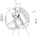
- Fig. 1D shows a detailed view (Detail B of Fig. 1C ) of a side cross-sectional view of Fig. 1C , focusing on click-in lock 103.
- Click-in lock 103a may have a lever 105 and a latch 108 as mentioned in reference to Fig. 1C .
- Latch 108 may be designed to fit into and to be inserted into and removed from mortise 107 of divider 106.
- Lever 105 may be connected to base 101 of inlet plug 100 ( Fig. 1A ) by axis 109.
- Axis 109 may be, for example a pin, hinge, screw etc.
- Axis 109 may be designed such that lever 105 rotates around axis 109.
- a torsion spring (not shown) may be placed between lever 105 and divider 106.
- the torsion spring may be designed to position lever 105, for example, when no torque is applied to the torsion spring, in a locked position (as shown), meaning that latch 108 is positioned fully or partially in mortise 107.
- Torque may be applied to the torsion spring by turning lever 105 around axis 109 towards divider 106, and latch 108 may be partially or fully taken out of mortise 107, unlocking click-in lock 103.
- click-in lock 103a may have a first magnet 110, mounted on lever 105, and a second magnet 111, mounted on divider 106. Magnets 110 and 111 may be magnetized in polarizations configured to reject each other. Click-in lock 103a may be designed to be normally locked because of the rejection force between magnets 110 and 111, and lever 105 may be positioned away from divider and latch 108 may be positioned fully or partially in mortise 107 (as shown). Force may be applied to lever 105 rotating lever 105 around axis 109 towards divider 106 and latch 108 partially or fully out of mortise 107.
- one of magnets 110 and 111 may be replaced with a rejecting material such as a metal, configured to reject an opposing magnet.
- magnet 110 may be replaced with a metal plate configured to reject and be rejected from and by magnet 111.
- Magnet 111 may be designed to be of a polarity to reject magnet 110 or a metal plate.
- magnets 110 and/or 111 may be electromagnets.
- An electromagnet may be designed to be magnetized when receiving an electric current higher than a certain threshold, and demagnetized when receiving a current under a certain threshold.
- a plug may be designed to be locked when an electric current over a certain threshold is applied to electromagnets 110 and 111, and unlocked when the electric current is under a certain threshold.
- Plug inlet 100 may include a switch designed to apply or cease a current configured to magnetize or demagnetize electromagnets 110 and 111.
- the switch may be a mechanical switch (such as a button, a flip-switch etc.), and may be an electrical switch, such as an RFID (radio frequency identification) key, fingerprint key, a keypad key, etc.
- plug inlet 100 may include magnets 110 and 111 designed to hold click-in lock 103 in a locked position configured to be unlocked and locked depending on a force applied to click-in lock 103a, and may include one or more electromagnets designed to hold click-in lock 103a in a locked position preventing the change of position of click-in lock 103a when the electromagnets are magnetically coupled.
- Click-in lock 103b may include magnets 110a and 111a, designed to attract each other.
- Magnet 111a may be mounted on latch 108, and magnet 110a may be mounted on divider 106, designed to be in proximity to magnet 111a when latch 108 is positioned in mortise 107.
- a magnetic force may be applied between magnets 111a and 110a, so that click-in lock may be normally closed.
- a mechanical force may be applied to lever 105.
- a finger may actuate that lever 105 by pressing down on the lever 105 thereby applying enough force to separate between magnets 110a and 111a.
- magnet 110a or magnet 111a may be replaced with a metalized area that may be magnetically drawn to magnet 111a or magnet 110a.
- plug inlet 100 may include a magnetic sensor (not shown) configured to sense a plug designed to plug into plug inlet 100.
- the magnetic sensor may sense a magnet mounted in and/or on a designated plug.
- the magnetic sensing may include sensing an angle of the plug in relation to plug inlet 100, the distance of the plug from plug inlet 100, sensing a level of connection between a corresponding plug and plug inlet 100. Sensing a level of connection may include, for example, determining whether or not the plug and plug inlet 100 clicked-in to each other, whether the plug and the plug inlet are touching but not clicked-in, or if the plug and plug inlet are not touching.
- FIG. 2 illustrates a plug inlet 200 including a socket 202 and a plurality of click-in locks 203a-203b.
- Plug inlet 200 may be designed to house a plug in socket 202, such as plug inlet 100 of Fig. 1A , and may be configured to lock a corresponding plug to plug inlet 200 by click-in locks 203a and 203b.
- Click-in locks 203a-203b may be positioned above, below and/or to a side of socket 202.
- plug inlet 200a may include one or more sockets, designed to house one or more plugs.
- plug inlet 200a may be designed to house an electrical vehicle plug.
- Plug inlet 200a may be placed in a garage designed to house two vehicles.
- Plug inlet 200a may have more than one socket.
- plug inlet 200a may have a first socket 201a designated to hold a charger for one of the vehicles in the garage and a second socket 201b for another vehicle in the garage.
- plug inlet 301 may include a communication device 303 configured to receive and/or transfer data to a plug designed to plug into socket 302.
- Communication device 303 may receive and/or transfer data using PLC, wired communication, wireless communication protocols (e.g., Bluetooth TM , ZigBee TM , WiFi TM , etc.), acoustic communication, etc.
- plug inlet 301a may further include a controller 304 (e.g., Digital Signal Processor (DSP), Microcontroller Unit (MCU), Field Programmable Gate Array (FPGA), Application Specific Integrated Circuit (ASIC), analog control circuit, etc.) and a sensor(s)/sensor interface(s) 305.
- controller 304 may be designed to activate the locking and unlocking of socket 302.
- socket 302 may include an electromagnet as mentioned in reference to Fig. ID.
- Controller 304 may activate and/or deactivate the electromagnet designed to lock and/or unlock socket 302 depending on data received from communication device 303.
- communication device 303 may receive a pairing signal from a corresponding plug
- controller 304 may receive the pairing signal and deactivate the electromagnet and unlock socket 302.
- sensor(s)/sensor interface(s) 305 may be configured to sense a corresponding plug.
- Controller 304 may be configured receive a measurement from sensor(s)/sensor interface(s) 305, such as distance, orientation, type etc. of the corresponding plug.
- User interface 306 may be configured to output the measurement, for example, user interface 306 may beep slowly if sensor(s)/sensor interface(s) 305 senses a plug from a first distance, and beep faster if sensor(s)/sensor interface(s) 305 senses the plug from a second distance closer than the first distance.
Landscapes
- Engineering & Computer Science (AREA)
- Power Engineering (AREA)
- Transportation (AREA)
- Mechanical Engineering (AREA)
- Microelectronics & Electronic Packaging (AREA)
- Manufacturing & Machinery (AREA)
- Details Of Connecting Devices For Male And Female Coupling (AREA)
- Electric Propulsion And Braking For Vehicles (AREA)
Applications Claiming Priority (2)
| Application Number | Priority Date | Filing Date | Title |
|---|---|---|---|
| US201862670935P | 2018-05-14 | 2018-05-14 | |
| EP19172251.1A EP3570383B1 (de) | 2018-05-14 | 2019-05-02 | Eingang für elektrischen stecker |
Related Parent Applications (1)
| Application Number | Title | Priority Date | Filing Date |
|---|---|---|---|
| EP19172251.1A Division EP3570383B1 (de) | 2018-05-14 | 2019-05-02 | Eingang für elektrischen stecker |
Publications (2)
| Publication Number | Publication Date |
|---|---|
| EP4235979A2 true EP4235979A2 (de) | 2023-08-30 |
| EP4235979A3 EP4235979A3 (de) | 2023-09-20 |
Family
ID=66379776
Family Applications (2)
| Application Number | Title | Priority Date | Filing Date |
|---|---|---|---|
| EP19172251.1A Active EP3570383B1 (de) | 2018-05-14 | 2019-05-02 | Eingang für elektrischen stecker |
| EP23172795.9A Pending EP4235979A3 (de) | 2018-05-14 | 2019-05-02 | Eingang für elektrischen stecker |
Family Applications Before (1)
| Application Number | Title | Priority Date | Filing Date |
|---|---|---|---|
| EP19172251.1A Active EP3570383B1 (de) | 2018-05-14 | 2019-05-02 | Eingang für elektrischen stecker |
Country Status (4)
| Country | Link |
|---|---|
| US (4) | US10864823B2 (de) |
| EP (2) | EP3570383B1 (de) |
| JP (1) | JP7421274B2 (de) |
| CN (2) | CN115663509A (de) |
Families Citing this family (4)
| Publication number | Priority date | Publication date | Assignee | Title |
|---|---|---|---|---|
| DE102019202352A1 (de) * | 2019-02-21 | 2020-08-27 | Jost-Werke Deutschland Gmbh | Verbindungseinrichtung, Verbindungssystem sowie Sattelzug |
| CN112977111B (zh) * | 2019-12-17 | 2022-08-26 | 河南美力达汽车有限公司 | 一种用于新能源汽车快充接口的锁紧机构 |
| CN111916940B (zh) * | 2020-01-18 | 2021-10-26 | 中国人民解放军海军潜艇学院 | 一种船舶岸电用的可识别的公母插头结构及对接方法 |
| DE202020002100U1 (de) * | 2020-05-13 | 2021-08-16 | Bob Holding Gmbh | Vorrichtung, insbesondere Ladestation oder Elektrofahrzeug, und Baugruppe für eine solche Vorrichtung |
Family Cites Families (18)
| Publication number | Priority date | Publication date | Assignee | Title |
|---|---|---|---|---|
| FR2451070B2 (fr) * | 1979-03-06 | 1985-11-22 | Cii Honeywell Bull | Connecteur pour objets portatifs, notamment des cartes de credit |
| US5413493A (en) * | 1993-01-15 | 1995-05-09 | Hubbell Incorporated | Electrical connector assembly, especially for electric vehicle |
| JPH10117405A (ja) * | 1996-10-11 | 1998-05-06 | Sumitomo Wiring Syst Ltd | 電気自動車充電用コネクタのホルダ |
| US20100228405A1 (en) * | 2007-06-13 | 2010-09-09 | Intrago Corporation | Shared vehicle management system |
| JP5171365B2 (ja) | 2008-04-11 | 2013-03-27 | 中国電力株式会社 | 差込接続器 |
| EP2552724B1 (de) * | 2010-03-31 | 2016-10-19 | Kiekert Aktiengesellschaft | Stellantrieb für ein kraftfahrzeug sowie verriegelungseinrichtung nebst verfahren |
| US20120126747A1 (en) * | 2010-11-19 | 2012-05-24 | Delphi Technologies, Inc. | Battery charger having non-contact electrical switch |
| US8651875B2 (en) * | 2011-09-28 | 2014-02-18 | Tesla Motors, Inc. | Electromechanical pawl for controlling vehicle charge inlet access |
| US8550833B2 (en) * | 2011-10-07 | 2013-10-08 | Ford Global Technologies, Llc | Locking apparatus for electric vehicle charging connector |
| FR2991658B1 (fr) * | 2012-06-11 | 2016-04-01 | Jcdecaux Sa | Systeme automatique de stockage de cycles et cycle pour un tel systeme. |
| DE102013000557B4 (de) * | 2013-01-14 | 2017-09-21 | Sudhaus Gmbh & Co. Kg | Magnetische Schließvorrichtung für Behältnisse, insbesondere für Weichgepäckstücke |
| JP6249756B2 (ja) | 2013-12-17 | 2017-12-20 | タキゲン製造株式会社 | 充電コネクター用ホルダー |
| DE102014101952B4 (de) * | 2014-02-17 | 2018-02-01 | Phoenix Contact E-Mobility Gmbh | Steckverbinderteil mit einem Rastelement |
| DE102014102197B4 (de) * | 2014-02-20 | 2019-02-14 | Phoenix Contact E-Mobility Gmbh | Steckverbinderteil mit einem Rastelement |
| US20170267114A1 (en) * | 2014-07-10 | 2017-09-21 | Control Module, Inc. | Shuttle System for Overhead EVSE |
| US9776521B2 (en) * | 2015-03-24 | 2017-10-03 | Ford Global Technologies, Llc | Vehicle and charging system for a vehicle |
| DE102015008761B3 (de) * | 2015-07-06 | 2016-11-10 | Cosi Elektronik Gmbh | Magnetischer Sicherheitsverschluss |
| DE102015113875A1 (de) * | 2015-08-21 | 2017-02-23 | Phoenix Contact E-Mobility Gmbh | Steckverbinderteil mit einem Verriegelungselement |
-
2019
- 2019-05-02 EP EP19172251.1A patent/EP3570383B1/de active Active
- 2019-05-02 EP EP23172795.9A patent/EP4235979A3/de active Pending
- 2019-05-07 US US16/405,633 patent/US10864823B2/en active Active
- 2019-05-10 CN CN202211273895.7A patent/CN115663509A/zh active Pending
- 2019-05-10 CN CN201910387644.3A patent/CN110492303B/zh active Active
- 2019-05-10 JP JP2019089719A patent/JP7421274B2/ja active Active
-
2020
- 2020-12-11 US US17/119,420 patent/US11440421B2/en active Active
-
2022
- 2022-07-27 US US17/874,539 patent/US11897352B2/en active Active
-
2023
- 2023-12-26 US US18/396,097 patent/US20240123847A1/en active Pending
Also Published As
| Publication number | Publication date |
|---|---|
| JP2019200989A (ja) | 2019-11-21 |
| US10864823B2 (en) | 2020-12-15 |
| EP4235979A3 (de) | 2023-09-20 |
| US20240123847A1 (en) | 2024-04-18 |
| US11440421B2 (en) | 2022-09-13 |
| JP7421274B2 (ja) | 2024-01-24 |
| CN110492303B (zh) | 2022-11-04 |
| EP3570383B1 (de) | 2023-05-17 |
| EP3570383A1 (de) | 2019-11-20 |
| CN115663509A (zh) | 2023-01-31 |
| US20190344675A1 (en) | 2019-11-14 |
| US20220363152A1 (en) | 2022-11-17 |
| US20210162878A1 (en) | 2021-06-03 |
| CN110492303A (zh) | 2019-11-22 |
| US11897352B2 (en) | 2024-02-13 |
Similar Documents
| Publication | Publication Date | Title |
|---|---|---|
| US11440421B2 (en) | Plug inlet for storing electrical vehicle plug | |
| EP3448057B1 (de) | Elektronische vorrichtung mit abdeckung mit einer öffnungs-/schliessstruktur unter verwendung von magnetkraft | |
| US10030417B1 (en) | Induction type padlock | |
| CN108700099B (zh) | 机械磁连接器结构 | |
| JP2016536497A (ja) | エネルギー効率の高い多安定錠シリンダ | |
| US10790628B2 (en) | Electronically actuated retaining latch for AC-DC adapter removable plug assembly | |
| US10687678B2 (en) | Power systems and methods including a battery charger and safety switch | |
| US20230178930A1 (en) | Locking mechanism for a high-current electrical connector | |
| US20170256970A1 (en) | Pairable usb cable locking charger | |
| US20210204738A1 (en) | Storage box and gimbal assembly having thereof | |
| CN112895929A (zh) | 车辆以及锁定控制系统 | |
| EP3440743B1 (de) | Vorrichtung zum anschliessen eines elektrischen gerätes, installiert auf einen beweglichen türblatt, an einer schaltung im stützrahmen eines solchen türblatts | |
| CN106953214A (zh) | 兼具两组不同电流插针组的连接器插头 | |
| CN110847721A (zh) | U型指纹挂锁 | |
| CN108974189B (zh) | 锁车机构和锁车桩 | |
| US11849550B2 (en) | Portable dock for electronic key retention devices | |
| CN212647096U (zh) | 一种带智能锁的分纤箱及其智能钥匙 | |
| CN211818712U (zh) | 一种磁铁锁装置 | |
| CN215344100U (zh) | 一种无线充电装置和带有锁定结构的装置 | |
| CN112360240A (zh) | 智能锁具 | |
| CN109653611A (zh) | 智能链锁 | |
| CN220726024U (zh) | 一种具有状态感应的智能门锁 | |
| CN212571537U (zh) | 门上设备的供电装置 | |
| CN216110157U (zh) | 电子钥匙和锁具组件 | |
| CN220522249U (zh) | 一种锁芯及转舌锁 |
Legal Events
| Date | Code | Title | Description |
|---|---|---|---|
| PUAI | Public reference made under article 153(3) epc to a published international application that has entered the european phase |
Free format text: ORIGINAL CODE: 0009012 |
|
| STAA | Information on the status of an ep patent application or granted ep patent |
Free format text: STATUS: REQUEST FOR EXAMINATION WAS MADE |
|
| REG | Reference to a national code |
Ref country code: DE Ref legal event code: R079 Free format text: PREVIOUS MAIN CLASS: H01R0013660000 Ipc: H01R0013443000 |
|
| PUAL | Search report despatched |
Free format text: ORIGINAL CODE: 0009013 |
|
| 17P | Request for examination filed |
Effective date: 20230511 |
|
| AC | Divisional application: reference to earlier application |
Ref document number: 3570383 Country of ref document: EP Kind code of ref document: P |
|
| AK | Designated contracting states |
Kind code of ref document: A2 Designated state(s): AL AT BE BG CH CY CZ DE DK EE ES FI FR GB GR HR HU IE IS IT LI LT LU LV MC MK MT NL NO PL PT RO RS SE SI SK SM TR |
|
| AK | Designated contracting states |
Kind code of ref document: A3 Designated state(s): AL AT BE BG CH CY CZ DE DK EE ES FI FR GB GR HR HU IE IS IT LI LT LU LV MC MK MT NL NO PL PT RO RS SE SI SK SM TR |
|
| RIC1 | Information provided on ipc code assigned before grant |
Ipc: H01R 13/66 20060101ALI20230816BHEP Ipc: H01R 13/703 20060101ALI20230816BHEP Ipc: H01R 13/627 20060101ALI20230816BHEP Ipc: H01R 13/62 20060101ALI20230816BHEP Ipc: E05B 47/00 20060101ALI20230816BHEP Ipc: H01R 13/443 20060101AFI20230816BHEP |
|
| P01 | Opt-out of the competence of the unified patent court (upc) registered |
Effective date: 20230901 |