EP4235809B9 - Elektrodenstruktur einer rückkontaktzelle - Google Patents
Elektrodenstruktur einer rückkontaktzelle Download PDFInfo
- Publication number
- EP4235809B9 EP4235809B9 EP22000133.3A EP22000133A EP4235809B9 EP 4235809 B9 EP4235809 B9 EP 4235809B9 EP 22000133 A EP22000133 A EP 22000133A EP 4235809 B9 EP4235809 B9 EP 4235809B9
- Authority
- EP
- European Patent Office
- Prior art keywords
- fingers
- busbar
- pad
- edge
- back contact
- Prior art date
- Legal status (The legal status is an assumption and is not a legal conclusion. Google has not performed a legal analysis and makes no representation as to the accuracy of the status listed.)
- Active
Links
Images


Classifications
-
- H—ELECTRICITY
- H10—SEMICONDUCTOR DEVICES; ELECTRIC SOLID-STATE DEVICES NOT OTHERWISE PROVIDED FOR
- H10F—INORGANIC SEMICONDUCTOR DEVICES SENSITIVE TO INFRARED RADIATION, LIGHT, ELECTROMAGNETIC RADIATION OF SHORTER WAVELENGTH OR CORPUSCULAR RADIATION
- H10F77/00—Constructional details of devices covered by this subclass
- H10F77/93—Interconnections
- H10F77/933—Interconnections for devices having potential barriers
- H10F77/935—Interconnections for devices having potential barriers for photovoltaic devices or modules
- H10F77/937—Busbar structures for modules
-
- H—ELECTRICITY
- H10—SEMICONDUCTOR DEVICES; ELECTRIC SOLID-STATE DEVICES NOT OTHERWISE PROVIDED FOR
- H10F—INORGANIC SEMICONDUCTOR DEVICES SENSITIVE TO INFRARED RADIATION, LIGHT, ELECTROMAGNETIC RADIATION OF SHORTER WAVELENGTH OR CORPUSCULAR RADIATION
- H10F10/00—Individual photovoltaic cells, e.g. solar cells
- H10F10/10—Individual photovoltaic cells, e.g. solar cells having potential barriers
- H10F10/14—Photovoltaic cells having only PN homojunction potential barriers
- H10F10/146—Back-junction photovoltaic cells, e.g. having interdigitated base-emitter regions on the back side
-
- H—ELECTRICITY
- H10—SEMICONDUCTOR DEVICES; ELECTRIC SOLID-STATE DEVICES NOT OTHERWISE PROVIDED FOR
- H10F—INORGANIC SEMICONDUCTOR DEVICES SENSITIVE TO INFRARED RADIATION, LIGHT, ELECTROMAGNETIC RADIATION OF SHORTER WAVELENGTH OR CORPUSCULAR RADIATION
- H10F19/00—Integrated devices, or assemblies of multiple devices, comprising at least one photovoltaic cell covered by group H10F10/00, e.g. photovoltaic modules
-
- H—ELECTRICITY
- H10—SEMICONDUCTOR DEVICES; ELECTRIC SOLID-STATE DEVICES NOT OTHERWISE PROVIDED FOR
- H10F—INORGANIC SEMICONDUCTOR DEVICES SENSITIVE TO INFRARED RADIATION, LIGHT, ELECTROMAGNETIC RADIATION OF SHORTER WAVELENGTH OR CORPUSCULAR RADIATION
- H10F77/00—Constructional details of devices covered by this subclass
- H10F77/20—Electrodes
- H10F77/206—Electrodes for devices having potential barriers
- H10F77/211—Electrodes for devices having potential barriers for photovoltaic cells
- H10F77/215—Geometries of grid contacts
-
- H—ELECTRICITY
- H10—SEMICONDUCTOR DEVICES; ELECTRIC SOLID-STATE DEVICES NOT OTHERWISE PROVIDED FOR
- H10F—INORGANIC SEMICONDUCTOR DEVICES SENSITIVE TO INFRARED RADIATION, LIGHT, ELECTROMAGNETIC RADIATION OF SHORTER WAVELENGTH OR CORPUSCULAR RADIATION
- H10F77/00—Constructional details of devices covered by this subclass
- H10F77/20—Electrodes
- H10F77/206—Electrodes for devices having potential barriers
- H10F77/211—Electrodes for devices having potential barriers for photovoltaic cells
- H10F77/219—Arrangements for electrodes of back-contact photovoltaic cells
- H10F77/227—Arrangements for electrodes of back-contact photovoltaic cells for emitter wrap-through [EWT] photovoltaic cells, e.g. interdigitated emitter-base back-contacts
Definitions
- a solar cell is a semiconductor device capable of converting light energy to electric energy.
- a solar cell that includes a back side connection layer containing current collecting lines and collection busbars is described, for example, in EP 3127169 A1 .
- Relatively low production costs and relatively high energy conversion efficiency have always been the goals pursued by the photovoltaic industry.
- an emitter contact electrode and a base contact electrode of the solar cell are respectively located on two opposite sides of the solar cell.
- a front side of the cell is a light-receiving surface.
- the coverage of a front metal emitter contact electrode inevitably causes part of incident sunlight to be reflected and blocked by a metal electrode, resulting in part of optical loss.
- a coverage area of a front metal electrode of an ordinary crystalline silicon solar cell is about 7%. Therefore, energy conversion efficiency of the cell may be directly enhanced by reducing the front coverage of the metal electrode.
- a back contact solar cell is a cell in which an emitter and a base contact electrode are both disposed on the back side (a non-light-receiving surface) of the cell.
- a light-receiving surface of the cell is not shielded by any metal electrode, thereby effectively increasing the short-circuit current of the cell.
- relatively wide metal fingers are allowed to be disposed on the back side to reduce a serial resistance, thereby increasing the fill factor.
- the cell with the front not shielded not only has high conversion efficiency, but also looks more beautiful.
- a module of an all back-contact electrode is easy to assemble.
- an electrode pattern design is a core technology of the cell.
- Three electrode pattern designs of the existing back contact solar cell are as follows.
- the second fingers comprise first bent
- the first bent fingers are respectively bent toward the first busbar and the first pad points, and are in contact with neither the first busbar nor the first pad points, or the first bent fingers are bent toward the first busbar and are not in contact with the first busbar, or the first bent fingers are bent toward the first pad points and are not in contact with the first pad points.
- the distance between each of the first pad points and the first edge ranges from 1 mm to 20 mm.
- the first fingers comprise second bent fingers between the second busbar and the second pad points, the second bent fingers are respectively bent toward the second busbar and the second pad points and are in contact with neither the second busbar nor the second pad points, or the second bent fingers are bent toward the second busbar and are not in contact with the second busbar, or the second bent fingers are bent toward the second pad points and are not in contact with the second pad points.
- each of the second bent fingers passes through at least one of the second fingers.
- a center line of each of the second connection electrodes and a center line of each of the second pad points are on a same straight line.
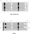
- the disclosure provides an electrode structure of a back contact cell according to the appended independent claim 1.
- the electrode structure comprises first fingers, second fingers, a first busbar, first pad points, and first connection electrodes respectively connected to the first busbar and the first pad points.
- the first fingers collect currents in a first polarity region, and the currents flow to the first busbar through the first pad points and the first connection electrodes, thereby realizing the collection of the currents.
- the first pad points and the first busbar are not simultaneously disposed on the first edge of the back contact cell, and the photo-generated electrons and holes are not required to cross a long distance to reach the region having an opposite polarity. In this way, the electrode structure can improve the reliability, reduce the costs, increase the product yield, and ensure excellent photoelectric conversion efficiency.
- a distance between each of the first pad points 31 and the first edge is greater than a distance between the first busbar 51 and the first edge.
- the polarities of the first fingers 10 in a blackened part is the same, the polarities of the second fingers 20 in an unprinted part are the same, and the polarities of the first fingers 10 and the second fingers 20 are opposite.
- the first pad points 31, the first connection electrodes 41, and the first busbar 51 in the blackened part have the same polarity as the first fingers 10.
- the distance between each of the first pad points 31 and the first edge is greater than the distance between the first busbar 51 and the first edge.
- a distance between a leftmost side of the first pad points 31 and an edge of a leftmost side of the back contact cell is greater than a distance between a leftmost side of the first busbar 51 and the edge of the leftmost side of the back contact cell.
- the distance between the first busbar 51 and the first edge ranges from 0.01 mm to 3 mm, which herein is the distance between an edge of the first busbar 51 close to the first edge and the first edge.
- the distance between the first busbar 51 and the first edge is 0.05 mm, 1 mm, 2 mm, 3 mm, or other parameter values from 0.01 mm to 3 mm.
- the distance between each of the first pad points 31 and the first edge ranges from 1 mm to 20 mm, which herein is the distance between an edge of the first pad point 31 close to the first edge and the first edge.
- the distance between the first pad point 31 and the first edge is 1 mm, 5 mm, 10 mm, 20 mm, or other parameter values from 1 mm to 20 mm, but the distance between the first pad point 31 and the first edge is greater than the distance between the first busbar 51 and the first edge.
- the first pad point 31 is disposed away from the first busbar 51, and the connection between the first pad point 31 and the first busbar 51 is realized by using the first connection electrode 41.
- the first busbar 51 is disposed on the first edge of the back contact cell, and the first pad point 31 is disposed away from the first edge of the back contact cell.
- the first finger 10 collects the currents of the first polarity region, then transmits the collected currents to the first pad point 31, and then transmits the collected currents from the first pad point 31 to the first busbar 51 through the first connection electrode 41 to complete the collection of the currents.
- the insulation paste in a large area of the electrode structure of the disclosure, and high-temperature paste may be selected for the first pad point 31 and the first busbar 51, thereby reducing the costs and ensuring the reliability.
- the heights of the first pad point 31 and the first busbar 51 are not required to be too high, so that the paste consumption is reduced.
- the problem of poor adhesion with some paste will not occur, thereby reducing the difficulty of mass production.
- the first busbar 51 is located at the first edge of the back contact cell, and the first pad point 31 is away from the first edge of the back contact cell, so as to avoid stress concentration in the welding process, thereby improving the yield of the module and improving the reliability of the module.
- the photo-generated electrons and holes are not required to cross a long distance to reach the region having the opposite polarity, to collect the currents, thereby fully ensuring relatively high photoelectric conversion efficiency.
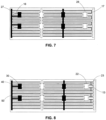
- a center line of each of the first connection electrodes 41 and a center line of each of the first pad points 31 in Embodiment 2 are not on the same straight line.
- the center line of the first pad point 31 is located on a setting line of the second fingers 20, and the polarities of the first pad points 31 and the second fingers 20 are opposite.
- the first pad point 31 has a positive polarity
- the second finger 20 has a negative polarity. Therefore, the center line of the first connection electrode 41 is disposed offset from the center line of the first pad point 31. That is, the center line of the first connection electrode 41 is disposed offset from the setting line of the second finger 20, so that the center line of the first connection electrode 41 may be disposed on the setting line of the first finger 10.
- the polarities of the first connection electrode 41 and the first finger 10 are the same, thereby achieving a more uniform distribution of fingers having opposite polarities in the region adjacent to the first pad point 31, and further improving the capability of current collection.
- the first connection electrode 41 is not in contact with a substrate of the back contact cell. At this point, the photo-generated electrons and holes in the region where the first connection electrode 41 is located cannot be effectively collected. Therefore, the third finger 18 is disposed in the region adjacent to the first connection electrode 41, and the third finger 18 may be in contact with the substrate, thereby further improving the capability of current collection.
- the second finger 20 of Embodiment 4 is covered with a first insulating material 62 in a partial region located on a center line of the first pad point 31.
- the first insulating material 62 may be covered with the insulation paste, where only the second finger 20 is covered with the insulation paste in the partial region located on the center line of the first pad point 31, which will not increase product costs.
- the first insulating material 62 may also adopt other implementations, as long as the purpose of insulation can be achieved.
- a distance between each of the second pad points 32 and the second edge is greater than a distance between the second busbar 52 and the second edge.
- the distance between the second busbar 52 and the second edge ranges from 0.01 mm to 3 mm, which herein is the distance between an edge of the second busbar 52 close to the second edge and the second edge.
- the distance between the second busbar 52 and the second edge is 0.05 mm, 1 mm, 2 mm, 3 mm, or other parameter values from 0.01 mm to 3 mm.
- the distance between each of the second pad points 32 and the second edge ranges from 1 mm to 20 mm, which herein is the distance between an edge of the second pad point 32 close to the second edge and the second edge.
- the busbars are located at the edge of the back contact cell, and the pad points are away from the edge of the back contact cell, so as to avoid stress concentration in the welding process, thereby improving the yield of the module and improving the reliability of the module.
- the photo-generated electrons and holes are not required to cross a long distance to reach the region having the opposite polarity, to collect the currents, thereby fully ensuring relatively high photoelectric conversion efficiency.
- the first finger 10 of the Embodiment 5 comprises second bent fingers located between the second busbar 52 and the second pad points 32, the second bent fingers are respectively bent toward the second busbar 52 and the second pad points 32 and are not in contact with the second busbar 52 and the second pad points 32, or the second bent fingers are bent toward the second busbar 52 and are not in contact with the second busbar 52, or the second bent fingers are bent toward the second pad point 32 and are not in contact with the second pad points 32.
- the second bent fingers are defined as fourth bent sub-fingers 13.
- the second fingers 20 comprise third pad point connection fingers 22 connected to the second pad points 32 and third busbar connection fingers 23 connected to the second busbar 52.
- the third pad point connection fingers 22 are disposed adjacent to the third busbar connection fingers 23, and a gap is formed therebetween.
- the fourth bent sub-fingers 13 pass through the gap, are respectively bent toward the second busbar 52 and the second pad points 32, and are in contact with neither the second busbar 52 nor the second pad points 32.
- the third pad point connection finger 22 and/or the third busbar connection finger 23 may be omitted. However, through arrangement of the third pad point connection finger 22 and/or the third busbar connection finger 23, the fingers may be disposed more uniformly, to cause the current collection in a small region to be implemented.
- the arrangement of the first bent finger and the second bent finger can be disposed on the edges of two ends of the back contact cell in different manners, and the arrangement mode of the first bent finger and the second bent finger may be selected according to an actual situation.
- the first edge of the back contact cell is not provided with the first bent finger
- the second edge of the back contact cell is provided with the second bent finger.
- the second bent fingers are respectively bent toward the second busbar 52 and the second pad point 32.
- a center line of the second connection electrode 42 and a center line of the second pad point 32 in Embodiment 6 are on a same straight line.
- the first finger 10 of Embodiment 8 is covered with a second insulating material 61 in a partial region located on a center line of the second pad point 32.
- the first finger 10 may be prevented from coming into contact with the ribbon in the partial region located on the center line of the second pad point 32, thereby effectively avoiding occurrence of short circuits.
- the second insulating material 61 is made after the second pad point 32 and the second busbar 52 are formed, and does not affect the selection of electrode materials for the second pad point 32 and the second busbar.
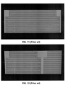
- FIG. 11 shows an edge model diagram based on the electrode structure of FIG. 2 .
- FIG. 12 shows an edge model diagram based on the electrode structure of FIG. 3 .
- FIG. 13 shows an edge model diagram based on the electrode structure of FIG. 4 .
- FIG. 14 shows an edge model diagram based on the electrode structure of FIG. 5 to FIG. 9 .
- the cell conversion efficiency is a key performance evaluation index for the back contact cell. Higher cell conversion efficiency leads to better performance, and every 0.1% increase is a breakthrough for the industry. It can be seen that the scheme of FIG. 3 is adopted, the problem of module yield and reliability is solved, but the performance is greatly reduced by 0.789%. If the scheme of FIG. 4 of the disclosure is adopted, the efficiency loss is reduced to 0.12% in a case that the module yield and reliability are solved. If the optimization scheme of FIG. 5 to FIG. 9 of the disclosure is adopted, the efficiency loss may be reduced to 0.003%. At present, the conversion efficiency test repeatability of the back contact cell is about ⁇ 0.05%, and the efficiency loss is too low to be monitored and can be ignored.
- the first pad point 31 is disposed away from the first busbar 51 , and the connection between the first pad point 31 and the first busbar 51 is realized by using the first connection electrode 41.
- the first busbar 51 is disposed on the first edge of the back contact cell, and the first pad point 31 is disposed away from the first edge of the back contact cell.
- the first finger 10 collects the currents of the first polarity region, then transmits the collected currents to the first pad point 31, and then transmits the collected currents from the first pad point 31 to the first busbar 51 through the first connection electrode 41 to complete the collection of the currents.
- the insulation paste in a large area of the electrode structure of the disclosure, and high-temperature paste may be selected for the first pad point 31 and the first busbar 51, thereby reducing the costs and ensuring the reliability.
- the heights of the first pad point 31 and the first busbar 51 are not required to be too high, so that the paste consumption is reduced.
- the problem of poor adhesion with some paste will not occur, thereby reducing the difficulty of mass production.
- the first busbar 51 is located at the first edge of the back contact cell, and the first pad point 31 is away from the first edge of the back contact cell, so as to avoid stress concentration in the welding process, thereby improving the yield of the module and improving the reliability of the module.
- the photo-generated electrons and holes are not required to cross a long distance to reach the region having the opposite polarity, to collect the currents, thereby fully ensuring relatively high photoelectric conversion efficiency.
- the insulation paste in a large area of the electrode structure of the disclosure, and high-temperature paste may be selected for the first pad point 31 and the first busbar 51, thereby reducing the costs and ensuring the reliability.
- the heights of the first pad point 31 and the first busbar 51 are not required to be too high, so that the paste consumption is reduced.
- the problem of poor adhesion with some paste will not occur, thereby reducing the difficulty of mass production.
Landscapes
- Photovoltaic Devices (AREA)
- Life Sciences & Earth Sciences (AREA)
- Engineering & Computer Science (AREA)
- Sustainable Development (AREA)
- Sustainable Energy (AREA)
- Electrodes Of Semiconductors (AREA)
- Secondary Cells (AREA)
- Battery Mounting, Suspending (AREA)
- Primary Cells (AREA)
Claims (18)
- Elektrodenstruktur einer Rückseitenkontaktzelle, wobei die Rückseitenkontaktzelle eine erste Polaritätsregion, eine zweite Polaritätsregion und einen ersten Rand umfasst, die Elektrodenstruktur umfassend:eine Vielzahl von ersten Fingern (10), die dazu konfiguriert sind, die erste Polaritätsregion zu erfassen;eine Vielzahl von zweiten Fingern (20), die dazu konfiguriert sind, die zweite Polaritätsregion zu erfassen;eine erste Sammelschiene (51), die auf einer Seite der Rückseitenkontaktzelle nahe an dem ersten Rand angeordnet und mit den ersten Fingern (10) verbunden ist;eine Vielzahl von ersten Kontaktpunkten (31); undeine Vielzahl von ersten Verbindungselektroden (41), die jeweils mit der ersten Sammelschiene (51) und den ersten Kontaktpunkten (31) verbunden sind; wobeiein Abstand zwischen jedem der ersten Kontaktpunkte (31) und dem ersten Rand größer ist als ein Abstand zwischen der ersten Sammelschiene (51) und dem ersten Rand; und gekennzeichnet dadurch, dass:
die zweiten Finger (20) erste gebogene Finger zwischen der ersten Sammelschiene (51) und den ersten Kontaktpunkten (31) umfassen, die ersten gebogenen Finger jeweils in Richtung der ersten Sammelschiene (51) und der ersten Kontaktpunkte (31) gebogen sind, und weder in Kontakt mit der ersten Sammelschiene (51) noch mit den ersten Kontaktpunkten (31) sind, oder die ersten gebogenen Finger in Richtung der ersten Sammelschiene (51) gebogen sind und nicht in Kontakt mit der ersten Sammelschiene (51) sind, oder die ersten gebogenen Finger in Richtung der ersten Kontaktpunkte (31) gebogen sind und nicht in Kontakt mit den ersten Kontaktpunkten (31) sind. - Elektrodenstruktur nach Anspruch 1, wobei jeder der ersten gebogenen Finger durch mindestens einen der ersten Finger verläuft.
- Elektrodenstruktur nach Anspruch 1, wobei eine Mittellinie jeder der ersten Verbindungselektroden (41) und eine Mittellinie jedes der ersten Kontaktpunkte (31) nicht auf einer selben geraden Linie liegen.
- Elektrodenstruktur nach Anspruch 1, ferner umfassend dritte Finger, die jeweils mit der ersten Sammelschiene (51) und den ersten Kontaktpunkten (31) verbunden sind, wobei die dritten Finger benachbart zu den ersten Verbindungselektroden (41) angeordnet sind, und eine Breite von jedem der dritten Finger geringer ist als eine Breite von jeder der ersten Verbindungselektroden (41).
- Elektrodenstruktur nach Anspruch 1, wobei jeder der zweiten Finger (20) in einer Teilregion einer Mittellinie von jedem der ersten Kontaktpunkte (31) mit einem ersten isolierenden Material bedeckt ist.
- Elektrodenstruktur nach Anspruch 1, wobei der Abstand zwischen der ersten Sammelschiene (51) und dem ersten Rand in einem Bereich von 0,01 mm bis 3 mm liegt.
- Elektrodenstruktur nach Anspruch 6, wobei der Abstand zwischen jedem der ersten Kontaktpunkte (31) und dem ersten Rand in einem Bereich von 1 mm bis 20 mm liegt.
- Elektrodenstruktur nach einem der Ansprüche 1-7, ferner umfassend:eine zweite Sammelschiene (52), die auf einer Seite der Rückseitenkontaktzelle nahe zu einem zweiten Rand der Rückseitenkontaktzelle angeordnet und mit der zweiten Sammelschiene (52) des zweiten Fingers (20) verbunden ist, wobei der zweite Rand gegenüber dem ersten Rand liegt;zweite Kontaktpunkte (32); undzweite Verbindungselektroden (42), die jeweils mit der zweiten Sammelschiene (52) und den zweiten Kontaktpunkten (32) verbunden sind; wobeiein Abstand zwischen jedem der zweiten Kontaktpunkte (32) und dem zweiten Rand größer ist als ein Abstand zwischen der zweiten Sammelschiene (52) und dem zweiten Rand.
- Elektrodenstruktur nach Anspruch 8, wobei die ersten Finger zweite gebogene Finger zwischen der zweiten Sammelschiene (52) und den zweiten Kontaktpunkten (32) umfassen, die zweiten gebogenen Finger jeweils in Richtung der zweiten Sammelschiene (52) und der zweiten Kontaktpunkte (32) gebogen sind, und weder in Kontakt mit der zweiten Sammelschiene (52) noch mit den zweiten Kontaktpunkten (32) sind, oder die zweiten gebogenen Finger in Richtung der zweiten Sammelschiene (52) gebogen sind und nicht in Kontakt mit der zweiten Sammelschiene (52) sind, oder die zweiten gebogenen Finger in Richtung der zweiten Kontaktpunkte (32) gebogen sind und nicht in Kontakt mit den zweiten Kontaktpunkten (32) sind.
- Elektrodenstruktur nach Anspruch 9, wobei jeder der zweiten gebogenen Finger durch mindestens einen der zweiten Finger (20) verläuft.
- Elektrodenstruktur nach Anspruch 9, wobei eine Mittellinie jeder der zweiten Verbindungselektroden (42) und eine Mittellinie jedes der zweiten Kontaktpunkte (32) auf einer selben geraden Linie liegen.
- Elektrodenstruktur nach Anspruch 9, ferner umfassend vierte Finger, die jeweils mit der zweiten Sammelschiene (52) und den zweiten Kontaktpunkten (32) verbunden sind, wobei die vierten Finger benachbart zu den zweiten Verbindungselektroden (42) angeordnet sind, und eine Breite von jedem der vierten Finger geringer ist als eine Breite von jeder der zweiten Verbindungselektroden (42).
- Elektrodenstruktur nach Anspruch 8, wobei jeder der ersten Finger in einer Teilregion einer Mittellinie von jedem der zweiten Kontaktpunkte (32) mit einem zweiten isolierenden Material bedeckt ist.
- Elektrodenstruktur nach Anspruch 8, wobei der Abstand zwischen der zweiten Sammelschiene (52) und dem zweiten Rand in einem Bereich von 0,01 mm bis 3 mm liegt.
- Elektrodenstruktur nach Anspruch 14, wobei der Abstand zwischen jedem der zweiten Kontaktpunkte (32) und dem zweiten Rand in einem Bereich von 1 mm bis 20 mm liegt.
- Rückseitenkontaktzelle, umfassend die Elektrodenstruktur nach einem der Ansprüche 1-15 und eine Rückseitenlichtfläche, wobei die Elektrodenstruktur auf der Rückseitenlichtfläche der Rückseitenkontaktzelle angeordnet ist.
- Rückseitenkontaktzellenmodul, umfassend die Rückseitenkontaktzelle nach Anspruch 16.
- Rückseitenkontaktzellensystem, umfassend das Rückseitenkontaktzellenmodul nach Anspruch 17.
Priority Applications (2)
| Application Number | Priority Date | Filing Date | Title |
|---|---|---|---|
| EP24188441.0A EP4421884A3 (de) | 2022-02-24 | 2022-05-13 | Elektrodenstruktur einer rückkontaktzelle, rückkontaktzelle, rückkontaktzellenmodul und rückkontaktzellensystem |
| EP24210613.6A EP4481831A3 (de) | 2022-02-24 | 2022-05-13 | Elektrodenstruktur einer rückkontaktzelle, rückkontaktzelle, rückkontaktgeliermodul und rückkontaktgeliersystem |
Applications Claiming Priority (1)
| Application Number | Priority Date | Filing Date | Title |
|---|---|---|---|
| CN202210168681.7A CN114242810B (zh) | 2022-02-24 | 2022-02-24 | 背接触电池的电极结构、电池、组件以及电池系统 |
Related Child Applications (4)
| Application Number | Title | Priority Date | Filing Date |
|---|---|---|---|
| EP24188441.0A Division EP4421884A3 (de) | 2022-02-24 | 2022-05-13 | Elektrodenstruktur einer rückkontaktzelle, rückkontaktzelle, rückkontaktzellenmodul und rückkontaktzellensystem |
| EP24188441.0A Division-Into EP4421884A3 (de) | 2022-02-24 | 2022-05-13 | Elektrodenstruktur einer rückkontaktzelle, rückkontaktzelle, rückkontaktzellenmodul und rückkontaktzellensystem |
| EP24210613.6A Division EP4481831A3 (de) | 2022-02-24 | 2022-05-13 | Elektrodenstruktur einer rückkontaktzelle, rückkontaktzelle, rückkontaktgeliermodul und rückkontaktgeliersystem |
| EP24210613.6A Division-Into EP4481831A3 (de) | 2022-02-24 | 2022-05-13 | Elektrodenstruktur einer rückkontaktzelle, rückkontaktzelle, rückkontaktgeliermodul und rückkontaktgeliersystem |
Publications (4)
| Publication Number | Publication Date |
|---|---|
| EP4235809A1 EP4235809A1 (de) | 2023-08-30 |
| EP4235809B1 EP4235809B1 (de) | 2025-01-29 |
| EP4235809C0 EP4235809C0 (de) | 2025-01-29 |
| EP4235809B9 true EP4235809B9 (de) | 2025-04-09 |
Family
ID=80747837
Family Applications (3)
| Application Number | Title | Priority Date | Filing Date |
|---|---|---|---|
| EP24210613.6A Pending EP4481831A3 (de) | 2022-02-24 | 2022-05-13 | Elektrodenstruktur einer rückkontaktzelle, rückkontaktzelle, rückkontaktgeliermodul und rückkontaktgeliersystem |
| EP24188441.0A Pending EP4421884A3 (de) | 2022-02-24 | 2022-05-13 | Elektrodenstruktur einer rückkontaktzelle, rückkontaktzelle, rückkontaktzellenmodul und rückkontaktzellensystem |
| EP22000133.3A Active EP4235809B9 (de) | 2022-02-24 | 2022-05-13 | Elektrodenstruktur einer rückkontaktzelle |
Family Applications Before (2)
| Application Number | Title | Priority Date | Filing Date |
|---|---|---|---|
| EP24210613.6A Pending EP4481831A3 (de) | 2022-02-24 | 2022-05-13 | Elektrodenstruktur einer rückkontaktzelle, rückkontaktzelle, rückkontaktgeliermodul und rückkontaktgeliersystem |
| EP24188441.0A Pending EP4421884A3 (de) | 2022-02-24 | 2022-05-13 | Elektrodenstruktur einer rückkontaktzelle, rückkontaktzelle, rückkontaktzellenmodul und rückkontaktzellensystem |
Country Status (11)
| Country | Link |
|---|---|
| US (2) | US20250120217A1 (de) |
| EP (3) | EP4481831A3 (de) |
| JP (4) | JP7401700B2 (de) |
| KR (1) | KR102570348B1 (de) |
| CN (1) | CN114242810B (de) |
| AU (2) | AU2023200965B2 (de) |
| DE (2) | DE202022003109U1 (de) |
| ES (1) | ES3009716T3 (de) |
| MX (1) | MX2023000068A (de) |
| MY (1) | MY204048A (de) |
| WO (1) | WO2022179747A2 (de) |
Families Citing this family (15)
| Publication number | Priority date | Publication date | Assignee | Title |
|---|---|---|---|---|
| CN114242810B (zh) * | 2022-02-24 | 2022-04-29 | 广东爱旭科技有限公司 | 背接触电池的电极结构、电池、组件以及电池系统 |
| CN116936650A (zh) * | 2022-04-08 | 2023-10-24 | 泰州隆基乐叶光伏科技有限公司 | 背接触太阳电池及电池组件、电极结构及其网版和电极结构的生产方法 |
| CN115148839A (zh) * | 2022-09-05 | 2022-10-04 | 浙江晶科能源有限公司 | 背接触太阳能电池及光伏组件 |
| CN119451268A (zh) * | 2022-09-14 | 2025-02-14 | 泰州隆基乐叶光伏科技有限公司 | 一种焊接方法及光伏组件 |
| CN117238980A (zh) * | 2022-10-24 | 2023-12-15 | 浙江晶科能源有限公司 | 太阳能电池及光伏组件 |
| US12080819B2 (en) | 2022-10-24 | 2024-09-03 | Zhejiang Jinko Solar Co., Ltd. | Solar cell and photovoltaic module |
| CN117038752A (zh) * | 2022-10-24 | 2023-11-10 | 浙江晶科能源有限公司 | 太阳能电池及光伏组件 |
| CN115579407B (zh) * | 2022-12-12 | 2023-03-14 | 浙江爱旭太阳能科技有限公司 | 电极结构、背接触太阳能电池片、电池组件和光伏系统 |
| CN116544287A (zh) * | 2023-01-05 | 2023-08-04 | 广东爱旭科技有限公司 | 背接触太阳能电池的电极结构、电池及其组件和光伏系统 |
| CN115810679B (zh) * | 2023-01-31 | 2023-04-28 | 金阳(泉州)新能源科技有限公司 | 一种背接触电池及其电极结构 |
| CN117219687B (zh) * | 2023-11-06 | 2024-03-12 | 晶科能源(海宁)有限公司 | 太阳能电池及光伏组件 |
| CN117438482B (zh) * | 2023-12-07 | 2024-06-28 | 浙江爱旭太阳能科技有限公司 | 背接触电池片、电池串、电池组件和光伏系统 |
| CN222282031U (zh) * | 2024-03-27 | 2024-12-31 | 隆基绿能科技股份有限公司 | 一种电池片、光伏组件及光伏系统 |
| CN118299439B (zh) * | 2024-05-06 | 2025-02-14 | 隆基绿能科技股份有限公司 | 一种背接触太阳能电池和光伏组件 |
| CN119855301A (zh) * | 2025-03-19 | 2025-04-18 | 嘉兴隆基光伏科技有限公司 | 太阳能电池及光伏组件 |
Family Cites Families (39)
| Publication number | Priority date | Publication date | Assignee | Title |
|---|---|---|---|---|
| US20050172996A1 (en) | 2004-02-05 | 2005-08-11 | Advent Solar, Inc. | Contact fabrication of emitter wrap-through back contact silicon solar cells |
| JP2007281044A (ja) * | 2006-04-04 | 2007-10-25 | Canon Inc | 太陽電池 |
| US20080216887A1 (en) * | 2006-12-22 | 2008-09-11 | Advent Solar, Inc. | Interconnect Technologies for Back Contact Solar Cells and Modules |
| US7804022B2 (en) | 2007-03-16 | 2010-09-28 | Sunpower Corporation | Solar cell contact fingers and solder pad arrangement for enhanced efficiency |
| JP5485062B2 (ja) * | 2010-07-30 | 2014-05-07 | 三洋電機株式会社 | 太陽電池の製造方法及び太陽電池 |
| JP2012074426A (ja) * | 2010-09-28 | 2012-04-12 | Sanyo Electric Co Ltd | 太陽電池、太陽電池モジュール及び太陽電池の製造方法 |
| JP2014053330A (ja) * | 2010-12-29 | 2014-03-20 | Sanyo Electric Co Ltd | 太陽電池 |
| WO2015183827A2 (en) * | 2014-05-27 | 2015-12-03 | Cogenra Solar, Inc. | Shingled solar cell module |
| WO2014176380A1 (en) * | 2013-04-23 | 2014-10-30 | Solexel, Inc. | Solar cell metallization |
| JP6126219B2 (ja) * | 2013-06-07 | 2017-05-10 | 信越化学工業株式会社 | バックコンタクト型太陽電池セル |
| TW201503388A (zh) | 2013-07-03 | 2015-01-16 | Neo Solar Power Corp | 背板串接型太陽能電池及其模組 |
| DE102013217356B4 (de) | 2013-08-30 | 2024-02-01 | Meyer Burger (Germany) Gmbh | Verfahren zum Herstellen eines Solarzellensegments und Verfahren zum Herstellen einer Solarzelle |
| NL2012554B1 (en) * | 2014-04-02 | 2016-02-15 | Stichting Energieonderzoek Centrum Nederland | Back side contact layer for PV module with by-pass configuration. |
| DE102015104236B4 (de) * | 2015-03-20 | 2021-11-18 | Fraunhofer-Gesellschaft zur Förderung der angewandten Forschung e.V. | Photovoltaische Solarzelle |
| EP3279947B1 (de) * | 2015-03-31 | 2022-07-13 | Kaneka Corporation | Solarbatterie und solarbatteriemodul |
| US10854767B2 (en) * | 2015-03-31 | 2020-12-01 | Kaneka Corporation | Solar cell and method for manufacturing same |
| KR101744535B1 (ko) * | 2015-07-21 | 2017-06-20 | 엘지전자 주식회사 | 태양 전지 및 이를 포함하는 태양 전지 패널 |
| CN106910782A (zh) * | 2015-12-23 | 2017-06-30 | 比亚迪股份有限公司 | 背接触太阳能电池片及其制备方法和背接触太阳能电池 |
| KR102622743B1 (ko) * | 2017-02-13 | 2024-01-10 | 상라오 신위안 웨동 테크놀러지 디벨롭먼트 컴퍼니, 리미티드 | 태양전지 및 태양전지 모듈 |
| CN106876496B (zh) * | 2017-03-03 | 2019-07-05 | 广东爱旭科技股份有限公司 | P型perc双面太阳能电池及其组件、系统和制备方法 |
| KR102459719B1 (ko) * | 2017-06-14 | 2022-10-27 | 상라오 징코 솔라 테크놀러지 디벨롭먼트 컴퍼니, 리미티드 | 태양 전지, 태양전지 모듈과 그 제조 방법 |
| CN207183286U (zh) | 2017-09-12 | 2018-04-03 | 国家电投集团西安太阳能电力有限公司 | 背接触晶硅电池电极网版结构 |
| CN108010970A (zh) * | 2017-11-17 | 2018-05-08 | 南通苏民新能源科技有限公司 | 一种叉指背接触晶体硅太阳能电池电极及其制作方法 |
| CN208767310U (zh) | 2018-05-29 | 2019-04-19 | 福建金石能源有限公司 | 一种可用于双面发电的太阳能背接触电池组件 |
| JP7176265B2 (ja) * | 2018-07-18 | 2022-11-22 | セイコーエプソン株式会社 | 裏面電極型光電変換素子、光電変換モジュールおよび電子機器 |
| JP7126909B2 (ja) | 2018-09-12 | 2022-08-29 | 東洋アルミニウム株式会社 | バックコンタクト型太陽電池セルの製造方法 |
| JP2022002230A (ja) * | 2018-09-21 | 2022-01-06 | 株式会社カネカ | 太陽電池セル、太陽電池デバイスおよび太陽電池モジュール |
| CN112673481B (zh) | 2018-09-28 | 2024-07-09 | 迈可晟太阳能有限公司 | 具有环绕式指状物的太阳能电池 |
| WO2020168380A1 (en) * | 2019-02-18 | 2020-08-27 | Newsouth Innovations Pty Limited | Method for reducing thermomechanical stress in solar cells |
| EP4006993A4 (de) * | 2019-07-31 | 2023-07-05 | Kaneka Corporation | Verfahren zur herstellung einer solarzelle, solarzelle, solarzellenvorrichtung und solarzellenmodul |
| CN210443569U (zh) * | 2019-09-20 | 2020-05-01 | 苏州阿特斯阳光电力科技有限公司 | 条形电池片、太阳能电池片及光伏组件 |
| CN212303683U (zh) * | 2020-04-24 | 2021-01-05 | 泰州隆基乐叶光伏科技有限公司 | 一种背接触太阳电池组件 |
| CN212303684U (zh) * | 2020-05-19 | 2021-01-05 | 泰州隆基乐叶光伏科技有限公司 | 一种背接触太阳电池组件 |
| CN213905367U (zh) * | 2020-10-23 | 2021-08-06 | 浙江爱旭太阳能科技有限公司 | 大尺寸n型单晶hbc太阳能电池的电极结构 |
| CN215183991U (zh) * | 2021-02-02 | 2021-12-14 | 苏州阿特斯阳光电力科技有限公司 | 电池片和具有其的光伏组件 |
| CN215988787U (zh) | 2021-06-30 | 2022-03-08 | 泰州隆基乐叶光伏科技有限公司 | 一种太阳能电池及光伏组件 |
| CN113327997B (zh) * | 2021-07-15 | 2025-10-03 | 浙江爱旭太阳能科技有限公司 | 一种背接触太阳能电池串及制备方法、组件及系统 |
| CN114242810B (zh) * | 2022-02-24 | 2022-04-29 | 广东爱旭科技有限公司 | 背接触电池的电极结构、电池、组件以及电池系统 |
| CN217588948U (zh) | 2022-04-08 | 2022-10-14 | 泰州隆基乐叶光伏科技有限公司 | 背接触太阳电池及电池组件、电极结构及其网版 |
-
2022
- 2022-02-24 CN CN202210168681.7A patent/CN114242810B/zh active Active
- 2022-05-13 ES ES22000133T patent/ES3009716T3/es active Active
- 2022-05-13 EP EP24210613.6A patent/EP4481831A3/de active Pending
- 2022-05-13 EP EP24188441.0A patent/EP4421884A3/de active Pending
- 2022-05-13 US US18/729,648 patent/US20250120217A1/en active Pending
- 2022-05-13 EP EP22000133.3A patent/EP4235809B9/de active Active
- 2022-05-13 DE DE202022003109.2U patent/DE202022003109U1/de active Active
- 2022-05-13 US US17/743,492 patent/US11588060B1/en active Active
- 2022-05-13 DE DE202022003108.4U patent/DE202022003108U1/de active Active
- 2022-05-13 WO PCT/EP2022/000045 patent/WO2022179747A2/en not_active Ceased
-
2023
- 2023-01-02 MX MX2023000068A patent/MX2023000068A/es unknown
- 2023-01-18 JP JP2023005695A patent/JP7401700B2/ja active Active
- 2023-01-19 KR KR1020230008250A patent/KR102570348B1/ko active Active
- 2023-02-17 AU AU2023200965A patent/AU2023200965B2/en active Active
- 2023-02-22 MY MYPI2023000920A patent/MY204048A/en unknown
- 2023-10-16 JP JP2023178143A patent/JP7699418B2/ja active Active
-
2024
- 2024-07-13 AU AU2024204838A patent/AU2024204838B2/en active Active
- 2024-07-16 JP JP2024113421A patent/JP7695450B2/ja active Active
-
2025
- 2025-06-13 JP JP2025099419A patent/JP2025120446A/ja active Pending
Also Published As
| Publication number | Publication date |
|---|---|
| CN114242810B (zh) | 2022-04-29 |
| JP2024138510A (ja) | 2024-10-08 |
| WO2022179747A2 (en) | 2022-09-01 |
| KR102570348B1 (ko) | 2023-08-23 |
| ES3009716T3 (en) | 2025-03-31 |
| US11588060B1 (en) | 2023-02-21 |
| JP7699418B2 (ja) | 2025-06-27 |
| EP4481831A3 (de) | 2025-03-19 |
| DE202022003108U1 (de) | 2024-12-13 |
| AU2024204838A1 (en) | 2024-08-01 |
| JP2023123356A (ja) | 2023-09-05 |
| AU2024204838B2 (en) | 2025-05-29 |
| AU2023200965A1 (en) | 2023-09-07 |
| JP2023179703A (ja) | 2023-12-19 |
| AU2023200965B2 (en) | 2025-01-30 |
| US20250120217A1 (en) | 2025-04-10 |
| DE202022003109U1 (de) | 2024-11-22 |
| WO2022179747A3 (en) | 2022-12-08 |
| EP4421884A3 (de) | 2024-11-20 |
| EP4235809B1 (de) | 2025-01-29 |
| JP7401700B2 (ja) | 2023-12-19 |
| EP4481831A2 (de) | 2024-12-25 |
| CN114242810A (zh) | 2022-03-25 |
| JP7695450B2 (ja) | 2025-06-18 |
| JP2025120446A (ja) | 2025-08-15 |
| EP4421884A2 (de) | 2024-08-28 |
| WO2022179747A9 (en) | 2022-10-20 |
| EP4235809A1 (de) | 2023-08-30 |
| MY204048A (en) | 2024-08-03 |
| EP4235809C0 (de) | 2025-01-29 |
| MX2023000068A (es) | 2023-08-25 |
Similar Documents
| Publication | Publication Date | Title |
|---|---|---|
| EP4235809B9 (de) | Elektrodenstruktur einer rückkontaktzelle | |
| CN105529373B (zh) | 一种晶硅太阳能电池的正面电极 | |
| EP3588585B1 (de) | Doppelseitige perc-solarzelle vom p-typ, anordnung dafür, system dafür und herstellungsverfahren dafür | |
| EP3591714B1 (de) | Doppelseitige perc-solarzelle vom p-typ, anordnung dafür, system dafür und herstellungsverfahren dafür | |
| EP4443522B1 (de) | Rückkontaktzelle, fotovoltaische zellenstruktur und fotovoltaische anordnung | |
| US12199203B2 (en) | Busbar-free interdigitated back contact solar cell and interdigitated back contact solar cell module | |
| CN222282016U (zh) | 一种背接触电池片 | |
| CN105633177A (zh) | 一种晶硅太阳能电池 | |
| CN209000938U (zh) | 一种背接触异质结太阳能电池组件的结构 | |
| CN105679849A (zh) | 一种晶硅太阳能电池 | |
| CN105552145B (zh) | 一种晶硅太阳能电池 | |
| US11688816B1 (en) | Electrode structure of back contact cell, back contact cell, back contact cell module, and back contact cell system | |
| CN106981527B (zh) | P型perc双面太阳能电池的背面电极和电池 | |
| CN109216475B (zh) | 一种太阳能电池板组件 | |
| CN223503326U (zh) | 一种硅基异质结背接触太阳能电池及光伏组件 | |
| CN206921832U (zh) | P型perc双面太阳能电池的背电极结构和电池 | |
| CN207338393U (zh) | P型perc双面太阳能电池的背面电极和电池 | |
| TR2024007243A1 (tr) | İç İçe Geçmiş Arkadan Bağlantılı Güneş Hücreleri İçin Metalizasyon Elek | |
| CN120882164A (zh) | Ibc太阳能电池片及ibc太阳能电池组件 | |
| CN106876498A (zh) | P型perc双面太阳能电池的背面电极和电池 |
Legal Events
| Date | Code | Title | Description |
|---|---|---|---|
| REG | Reference to a national code |
Ref country code: DE Ref legal event code: R138 Ref document number: 202022003109 Country of ref document: DE Free format text: GERMAN DOCUMENT NUMBER IS 602022009882 Ref country code: DE Ref legal event code: R138 Ref document number: 202022003108 Country of ref document: DE Free format text: GERMAN DOCUMENT NUMBER IS 602022009882 |
|
| PUAI | Public reference made under article 153(3) epc to a published international application that has entered the european phase |
Free format text: ORIGINAL CODE: 0009012 |
|
| STAA | Information on the status of an ep patent application or granted ep patent |
Free format text: STATUS: REQUEST FOR EXAMINATION WAS MADE |
|
| 17P | Request for examination filed |
Effective date: 20220615 |
|
| AK | Designated contracting states |
Kind code of ref document: A1 Designated state(s): AL AT BE BG CH CY CZ DE DK EE ES FI FR GB GR HR HU IE IS IT LI LT LU LV MC MK MT NL NO PL PT RO RS SE SI SK SM TR |
|
| GRAP | Despatch of communication of intention to grant a patent |
Free format text: ORIGINAL CODE: EPIDOSNIGR1 |
|
| STAA | Information on the status of an ep patent application or granted ep patent |
Free format text: STATUS: GRANT OF PATENT IS INTENDED |
|
| INTG | Intention to grant announced |
Effective date: 20240705 |
|
| P01 | Opt-out of the competence of the unified patent court (upc) registered |
Free format text: CASE NUMBER: APP_51883/2024 Effective date: 20240916 |
|
| GRAS | Grant fee paid |
Free format text: ORIGINAL CODE: EPIDOSNIGR3 |
|
| GRAA | (expected) grant |
Free format text: ORIGINAL CODE: 0009210 |
|
| STAA | Information on the status of an ep patent application or granted ep patent |
Free format text: STATUS: THE PATENT HAS BEEN GRANTED |
|
| AK | Designated contracting states |
Kind code of ref document: B1 Designated state(s): AL AT BE BG CH CY CZ DE DK EE ES FI FR GB GR HR HU IE IS IT LI LT LU LV MC MK MT NL NO PL PT RO RS SE SI SK SM TR |
|
| REG | Reference to a national code |
Ref country code: GB Ref legal event code: FG4D |
|
| REG | Reference to a national code |
Ref country code: CH Ref legal event code: EP |
|
| REG | Reference to a national code |
Ref country code: DE Ref legal event code: R096 Ref document number: 602022009882 Country of ref document: DE |
|
| REG | Reference to a national code |
Ref country code: IE Ref legal event code: FG4D Ref country code: NL Ref legal event code: FP |
|
| REG | Reference to a national code |
Ref country code: CH Ref legal event code: PK Free format text: BERICHTIGUNG B9 |
|
| REG | Reference to a national code |
Ref country code: ES Ref legal event code: FG2A Ref document number: 3009716 Country of ref document: ES Kind code of ref document: T3 Effective date: 20250331 |
|
| U01 | Request for unitary effect filed |
Effective date: 20250227 |
|
| P04 | Withdrawal of opt-out of the competence of the unified patent court (upc) registered |
Free format text: CASE NUMBER: APP_10346/2025 Effective date: 20250301 |
|
| U07 | Unitary effect registered |
Designated state(s): AT BE BG DE DK EE FI FR IT LT LU LV MT NL PT RO SE SI Effective date: 20250305 |
|
| RAP2 | Party data changed (patent owner data changed or rights of a patent transferred) |
Owner name: LONGI SOLAR TECHNOLOGIE GMBH Owner name: LONGI GREEN ENERGY TECHNOLOGY CO., LTD. Owner name: SOLARLAB AIKO EUROPE GMBH |
|
| U1H | Name or address of the proprietor changed after the registration of the unitary effect |
Owner name: LONGI SOLAR TECHNOLOGIE GMBH; DE Owner name: LONGI GREEN ENERGY TECHNOLOGY CO., LTD.; CN Owner name: SOLARLAB AIKO EUROPE GMBH; DE |
|
| REG | Reference to a national code |
Ref country code: GB Ref legal event code: 732E Free format text: REGISTERED BETWEEN 20250515 AND 20250521 |
|
| U20 | Renewal fee for the european patent with unitary effect paid |
Year of fee payment: 4 Effective date: 20250523 |
|
| PG25 | Lapsed in a contracting state [announced via postgrant information from national office to epo] |
Ref country code: RS Free format text: LAPSE BECAUSE OF FAILURE TO SUBMIT A TRANSLATION OF THE DESCRIPTION OR TO PAY THE FEE WITHIN THE PRESCRIBED TIME-LIMIT Effective date: 20250429 |
|
| PG25 | Lapsed in a contracting state [announced via postgrant information from national office to epo] |
Ref country code: PL Free format text: LAPSE BECAUSE OF FAILURE TO SUBMIT A TRANSLATION OF THE DESCRIPTION OR TO PAY THE FEE WITHIN THE PRESCRIBED TIME-LIMIT Effective date: 20250129 |
|
| PGFP | Annual fee paid to national office [announced via postgrant information from national office to epo] |
Ref country code: ES Payment date: 20250626 Year of fee payment: 4 |
|
| PG25 | Lapsed in a contracting state [announced via postgrant information from national office to epo] |
Ref country code: IS Free format text: LAPSE BECAUSE OF FAILURE TO SUBMIT A TRANSLATION OF THE DESCRIPTION OR TO PAY THE FEE WITHIN THE PRESCRIBED TIME-LIMIT Effective date: 20250529 Ref country code: NO Free format text: LAPSE BECAUSE OF FAILURE TO SUBMIT A TRANSLATION OF THE DESCRIPTION OR TO PAY THE FEE WITHIN THE PRESCRIBED TIME-LIMIT Effective date: 20250429 |
|
| PG25 | Lapsed in a contracting state [announced via postgrant information from national office to epo] |
Ref country code: HR Free format text: LAPSE BECAUSE OF FAILURE TO SUBMIT A TRANSLATION OF THE DESCRIPTION OR TO PAY THE FEE WITHIN THE PRESCRIBED TIME-LIMIT Effective date: 20250129 |
|
| PG25 | Lapsed in a contracting state [announced via postgrant information from national office to epo] |
Ref country code: GR Free format text: LAPSE BECAUSE OF FAILURE TO SUBMIT A TRANSLATION OF THE DESCRIPTION OR TO PAY THE FEE WITHIN THE PRESCRIBED TIME-LIMIT Effective date: 20250430 |
|
| PGFP | Annual fee paid to national office [announced via postgrant information from national office to epo] |
Ref country code: CH Payment date: 20250601 Year of fee payment: 4 |
|
| PG25 | Lapsed in a contracting state [announced via postgrant information from national office to epo] |
Ref country code: SM Free format text: LAPSE BECAUSE OF FAILURE TO SUBMIT A TRANSLATION OF THE DESCRIPTION OR TO PAY THE FEE WITHIN THE PRESCRIBED TIME-LIMIT Effective date: 20250129 |
|
| PG25 | Lapsed in a contracting state [announced via postgrant information from national office to epo] |
Ref country code: CZ Free format text: LAPSE BECAUSE OF FAILURE TO SUBMIT A TRANSLATION OF THE DESCRIPTION OR TO PAY THE FEE WITHIN THE PRESCRIBED TIME-LIMIT Effective date: 20250129 |
|
| PG25 | Lapsed in a contracting state [announced via postgrant information from national office to epo] |
Ref country code: SK Free format text: LAPSE BECAUSE OF FAILURE TO SUBMIT A TRANSLATION OF THE DESCRIPTION OR TO PAY THE FEE WITHIN THE PRESCRIBED TIME-LIMIT Effective date: 20250129 |
|
| PLBE | No opposition filed within time limit |
Free format text: ORIGINAL CODE: 0009261 |
|
| STAA | Information on the status of an ep patent application or granted ep patent |
Free format text: STATUS: NO OPPOSITION FILED WITHIN TIME LIMIT |
|
| 26N | No opposition filed |
Effective date: 20251030 |
|
| PG25 | Lapsed in a contracting state [announced via postgrant information from national office to epo] |
Ref country code: MC Free format text: LAPSE BECAUSE OF FAILURE TO SUBMIT A TRANSLATION OF THE DESCRIPTION OR TO PAY THE FEE WITHIN THE PRESCRIBED TIME-LIMIT Effective date: 20250129 |