EP4235684B1 - Systeme und verfahren zur verarbeitung und übertragung von sensordaten - Google Patents
Systeme und verfahren zur verarbeitung und übertragung von sensordaten Download PDFInfo
- Publication number
- EP4235684B1 EP4235684B1 EP23173573.9A EP23173573A EP4235684B1 EP 4235684 B1 EP4235684 B1 EP 4235684B1 EP 23173573 A EP23173573 A EP 23173573A EP 4235684 B1 EP4235684 B1 EP 4235684B1
- Authority
- EP
- European Patent Office
- Prior art keywords
- sensor
- electronics module
- patent publication
- display device
- data
- Prior art date
- Legal status (The legal status is an assumption and is not a legal conclusion. Google has not performed a legal analysis and makes no representation as to the accuracy of the status listed.)
- Active
Links
Images


Classifications
-
- G—PHYSICS
- G16—INFORMATION AND COMMUNICATION TECHNOLOGY [ICT] SPECIALLY ADAPTED FOR SPECIFIC APPLICATION FIELDS
- G16H—HEALTHCARE INFORMATICS, i.e. INFORMATION AND COMMUNICATION TECHNOLOGY [ICT] SPECIALLY ADAPTED FOR THE HANDLING OR PROCESSING OF MEDICAL OR HEALTHCARE DATA
- G16H40/00—ICT specially adapted for the management or administration of healthcare resources or facilities; ICT specially adapted for the management or operation of medical equipment or devices
- G16H40/60—ICT specially adapted for the management or administration of healthcare resources or facilities; ICT specially adapted for the management or operation of medical equipment or devices for the operation of medical equipment or devices
- G16H40/67—ICT specially adapted for the management or administration of healthcare resources or facilities; ICT specially adapted for the management or operation of medical equipment or devices for the operation of medical equipment or devices for remote operation
-
- A—HUMAN NECESSITIES
- A61—MEDICAL OR VETERINARY SCIENCE; HYGIENE
- A61B—DIAGNOSIS; SURGERY; IDENTIFICATION
- A61B5/00—Measuring for diagnostic purposes; Identification of persons
- A61B5/0002—Remote monitoring of patients using telemetry, e.g. transmission of vital signals via a communication network
- A61B5/0015—Remote monitoring of patients using telemetry, e.g. transmission of vital signals via a communication network characterised by features of the telemetry system
-
- A—HUMAN NECESSITIES
- A61—MEDICAL OR VETERINARY SCIENCE; HYGIENE
- A61B—DIAGNOSIS; SURGERY; IDENTIFICATION
- A61B5/00—Measuring for diagnostic purposes; Identification of persons
- A61B5/07—Endoradiosondes
- A61B5/076—Permanent implantation
-
- A—HUMAN NECESSITIES
- A61—MEDICAL OR VETERINARY SCIENCE; HYGIENE
- A61B—DIAGNOSIS; SURGERY; IDENTIFICATION
- A61B5/00—Measuring for diagnostic purposes; Identification of persons
- A61B5/145—Measuring characteristics of blood in vivo, e.g. gas concentration or pH-value ; Measuring characteristics of body fluids or tissues, e.g. interstitial fluid or cerebral tissue
- A61B5/14503—Measuring characteristics of blood in vivo, e.g. gas concentration or pH-value ; Measuring characteristics of body fluids or tissues, e.g. interstitial fluid or cerebral tissue invasive, e.g. introduced into the body by a catheter or needle or using implanted sensors
-
- A—HUMAN NECESSITIES
- A61—MEDICAL OR VETERINARY SCIENCE; HYGIENE
- A61B—DIAGNOSIS; SURGERY; IDENTIFICATION
- A61B5/00—Measuring for diagnostic purposes; Identification of persons
- A61B5/145—Measuring characteristics of blood in vivo, e.g. gas concentration or pH-value ; Measuring characteristics of body fluids or tissues, e.g. interstitial fluid or cerebral tissue
- A61B5/14532—Measuring characteristics of blood in vivo, e.g. gas concentration or pH-value ; Measuring characteristics of body fluids or tissues, e.g. interstitial fluid or cerebral tissue for measuring glucose, e.g. by tissue impedance measurement
-
- A—HUMAN NECESSITIES
- A61—MEDICAL OR VETERINARY SCIENCE; HYGIENE
- A61B—DIAGNOSIS; SURGERY; IDENTIFICATION
- A61B5/00—Measuring for diagnostic purposes; Identification of persons
- A61B5/145—Measuring characteristics of blood in vivo, e.g. gas concentration or pH-value ; Measuring characteristics of body fluids or tissues, e.g. interstitial fluid or cerebral tissue
- A61B5/1468—Measuring characteristics of blood in vivo, e.g. gas concentration or pH-value ; Measuring characteristics of body fluids or tissues, e.g. interstitial fluid or cerebral tissue using chemical or electrochemical methods, e.g. by polarographic means
- A61B5/1486—Measuring characteristics of blood in vivo, e.g. gas concentration or pH-value ; Measuring characteristics of body fluids or tissues, e.g. interstitial fluid or cerebral tissue using chemical or electrochemical methods, e.g. by polarographic means using enzyme electrodes, e.g. with immobilised oxidase
- A61B5/14865—Measuring characteristics of blood in vivo, e.g. gas concentration or pH-value ; Measuring characteristics of body fluids or tissues, e.g. interstitial fluid or cerebral tissue using chemical or electrochemical methods, e.g. by polarographic means using enzyme electrodes, e.g. with immobilised oxidase invasive, e.g. introduced into the body by a catheter or needle or using implanted sensors
-
- A—HUMAN NECESSITIES
- A61—MEDICAL OR VETERINARY SCIENCE; HYGIENE
- A61B—DIAGNOSIS; SURGERY; IDENTIFICATION
- A61B5/00—Measuring for diagnostic purposes; Identification of persons
- A61B5/68—Arrangements of detecting, measuring or recording means, e.g. sensors, in relation to patient
- A61B5/6846—Arrangements of detecting, measuring or recording means, e.g. sensors, in relation to patient specially adapted to be brought in contact with an internal body part, i.e. invasive
- A61B5/6847—Arrangements of detecting, measuring or recording means, e.g. sensors, in relation to patient specially adapted to be brought in contact with an internal body part, i.e. invasive mounted on an invasive device
- A61B5/6848—Needles
- A61B5/6849—Needles in combination with a needle set
-
- A—HUMAN NECESSITIES
- A61—MEDICAL OR VETERINARY SCIENCE; HYGIENE
- A61B—DIAGNOSIS; SURGERY; IDENTIFICATION
- A61B5/00—Measuring for diagnostic purposes; Identification of persons
- A61B5/74—Details of notification to user or communication with user or patient; User input means
- A61B5/742—Details of notification to user or communication with user or patient; User input means using visual displays
-
- A—HUMAN NECESSITIES
- A61—MEDICAL OR VETERINARY SCIENCE; HYGIENE
- A61B—DIAGNOSIS; SURGERY; IDENTIFICATION
- A61B5/00—Measuring for diagnostic purposes; Identification of persons
- A61B5/74—Details of notification to user or communication with user or patient; User input means
- A61B5/7475—User input or interface means, e.g. keyboard, pointing device, joystick
-
- G—PHYSICS
- G16—INFORMATION AND COMMUNICATION TECHNOLOGY [ICT] SPECIALLY ADAPTED FOR SPECIFIC APPLICATION FIELDS
- G16H—HEALTHCARE INFORMATICS, i.e. INFORMATION AND COMMUNICATION TECHNOLOGY [ICT] SPECIALLY ADAPTED FOR THE HANDLING OR PROCESSING OF MEDICAL OR HEALTHCARE DATA
- G16H20/00—ICT specially adapted for therapies or health-improving plans, e.g. for handling prescriptions, for steering therapy or for monitoring patient compliance
- G16H20/10—ICT specially adapted for therapies or health-improving plans, e.g. for handling prescriptions, for steering therapy or for monitoring patient compliance relating to drugs or medications, e.g. for ensuring correct administration to patients
- G16H20/17—ICT specially adapted for therapies or health-improving plans, e.g. for handling prescriptions, for steering therapy or for monitoring patient compliance relating to drugs or medications, e.g. for ensuring correct administration to patients delivered via infusion or injection
-
- G—PHYSICS
- G16—INFORMATION AND COMMUNICATION TECHNOLOGY [ICT] SPECIALLY ADAPTED FOR SPECIFIC APPLICATION FIELDS
- G16H—HEALTHCARE INFORMATICS, i.e. INFORMATION AND COMMUNICATION TECHNOLOGY [ICT] SPECIALLY ADAPTED FOR THE HANDLING OR PROCESSING OF MEDICAL OR HEALTHCARE DATA
- G16H30/00—ICT specially adapted for the handling or processing of medical images
- G16H30/20—ICT specially adapted for the handling or processing of medical images for handling medical images, e.g. DICOM, HL7 or PACS
-
- G—PHYSICS
- G16—INFORMATION AND COMMUNICATION TECHNOLOGY [ICT] SPECIALLY ADAPTED FOR SPECIFIC APPLICATION FIELDS
- G16H—HEALTHCARE INFORMATICS, i.e. INFORMATION AND COMMUNICATION TECHNOLOGY [ICT] SPECIALLY ADAPTED FOR THE HANDLING OR PROCESSING OF MEDICAL OR HEALTHCARE DATA
- G16H40/00—ICT specially adapted for the management or administration of healthcare resources or facilities; ICT specially adapted for the management or operation of medical equipment or devices
- G16H40/20—ICT specially adapted for the management or administration of healthcare resources or facilities; ICT specially adapted for the management or operation of medical equipment or devices for the management or administration of healthcare resources or facilities, e.g. managing hospital staff or surgery rooms
-
- G—PHYSICS
- G16—INFORMATION AND COMMUNICATION TECHNOLOGY [ICT] SPECIALLY ADAPTED FOR SPECIFIC APPLICATION FIELDS
- G16H—HEALTHCARE INFORMATICS, i.e. INFORMATION AND COMMUNICATION TECHNOLOGY [ICT] SPECIALLY ADAPTED FOR THE HANDLING OR PROCESSING OF MEDICAL OR HEALTHCARE DATA
- G16H40/00—ICT specially adapted for the management or administration of healthcare resources or facilities; ICT specially adapted for the management or operation of medical equipment or devices
- G16H40/40—ICT specially adapted for the management or administration of healthcare resources or facilities; ICT specially adapted for the management or operation of medical equipment or devices for the management of medical equipment or devices, e.g. scheduling maintenance or upgrades
-
- G—PHYSICS
- G16—INFORMATION AND COMMUNICATION TECHNOLOGY [ICT] SPECIALLY ADAPTED FOR SPECIFIC APPLICATION FIELDS
- G16H—HEALTHCARE INFORMATICS, i.e. INFORMATION AND COMMUNICATION TECHNOLOGY [ICT] SPECIALLY ADAPTED FOR THE HANDLING OR PROCESSING OF MEDICAL OR HEALTHCARE DATA
- G16H50/00—ICT specially adapted for medical diagnosis, medical simulation or medical data mining; ICT specially adapted for detecting, monitoring or modelling epidemics or pandemics
- G16H50/20—ICT specially adapted for medical diagnosis, medical simulation or medical data mining; ICT specially adapted for detecting, monitoring or modelling epidemics or pandemics for computer-aided diagnosis, e.g. based on medical expert systems
-
- A—HUMAN NECESSITIES
- A61—MEDICAL OR VETERINARY SCIENCE; HYGIENE
- A61B—DIAGNOSIS; SURGERY; IDENTIFICATION
- A61B2560/00—Constructional details of operational features of apparatus; Accessories for medical measuring apparatus
- A61B2560/02—Operational features
- A61B2560/0204—Operational features of power management
- A61B2560/0209—Operational features of power management adapted for power saving
-
- G—PHYSICS
- G16—INFORMATION AND COMMUNICATION TECHNOLOGY [ICT] SPECIALLY ADAPTED FOR SPECIFIC APPLICATION FIELDS
- G16H—HEALTHCARE INFORMATICS, i.e. INFORMATION AND COMMUNICATION TECHNOLOGY [ICT] SPECIALLY ADAPTED FOR THE HANDLING OR PROCESSING OF MEDICAL OR HEALTHCARE DATA
- G16H10/00—ICT specially adapted for the handling or processing of patient-related medical or healthcare data
- G16H10/60—ICT specially adapted for the handling or processing of patient-related medical or healthcare data for patient-specific data, e.g. for electronic patient records
-
- Y—GENERAL TAGGING OF NEW TECHNOLOGICAL DEVELOPMENTS; GENERAL TAGGING OF CROSS-SECTIONAL TECHNOLOGIES SPANNING OVER SEVERAL SECTIONS OF THE IPC; TECHNICAL SUBJECTS COVERED BY FORMER USPC CROSS-REFERENCE ART COLLECTIONS [XRACs] AND DIGESTS
- Y02—TECHNOLOGIES OR APPLICATIONS FOR MITIGATION OR ADAPTATION AGAINST CLIMATE CHANGE
- Y02D—CLIMATE CHANGE MITIGATION TECHNOLOGIES IN INFORMATION AND COMMUNICATION TECHNOLOGIES [ICT], I.E. INFORMATION AND COMMUNICATION TECHNOLOGIES AIMING AT THE REDUCTION OF THEIR OWN ENERGY USE
- Y02D30/00—Reducing energy consumption in communication networks
- Y02D30/70—Reducing energy consumption in communication networks in wireless communication networks
Definitions
- the present invention relates generally to systems and methods for processing, transmitting and displaying data received from an analyte sensor, such as a glucose sensor.
- Diabetes mellitus is a disorder in which the pancreas cannot create sufficient insulin (Type 1 or insulin dependent) and/or in which insulin is not effective (Type 2 or non-insulin dependent).
- Type 1 or insulin dependent in which the pancreas cannot create sufficient insulin
- Type 2 or non-insulin dependent in which insulin is not effective
- a hypoglycemic reaction low blood sugar may be induced by an inadvertent overdose of insulin, or after a normal dose of insulin or glucose-lowering agent accompanied by extraordinary exercise or insufficient food intake.
- a method, system or computer software product for transmitting data between devices of an analyte monitoring system comprises: generating sensor data using a sensor electronics module electrically connected to a continuous analyte sensor; establishing a two-way communication channel between the sensor electronics module and the a display device and each of the sensor electronics module and display device transmitting at a first transmission power; and initiating a low power transmission mode responsive to receiving user input at user interface of the display device indicative of entering the mode, wherein the low power transmission mode comprises one or both of the sensor electronics module and the display device transmitting at a second transmission power that is lower than the first transmission power.
- sensor data point and “data point” refer generally to a digital representation of sensor data at a particular time.
- the term broadly encompasses a plurality of time spaced data points from a sensor, such as a from a substantially continuous glucose sensor, which comprises individual measurements taken at time intervals ranging from fractions of a second up to, e.g., 1, 2, or 5 minutes or longer.
- the sensor data includes an integrated digital value representative of one or more data points averaged over a time period.
- Sensor data may include calibrated data, smoothed data, filtered data, transformed data, and/or any other data associated with a sensor.
- a glucose sensor comprises a continuous analyte sensor, such as is described in U.S. Patent 7,310,544 .
- sensor information is a broad term, and is to be given its ordinary and customary meaning to a person of ordinary skill in the art, and furthermore refers without limitation to information associated with measurement, signal processing (including calibration), alarms, data transmission, and/or display associated with a sensor, such as a continuous analyte sensor.
- the term is broad enough to include raw sensor data (one or more raw analyte concentration values), as well as transformed sensor data.
- sensor information includes displayable sensor information.
- a data package is a broad term, and is to be given its ordinary and customary meaning to a person of ordinary skill in the art, and furthermore refers without limitation to a combination of data that is transmitted to one or more display devices, such as in response to triggering of an alert.
- a data package may include displayable sensor information (e.g., that has been selected and formatted for a particular display device) as well as header information, such as data indicating a delivery address, communication protocol, etc.
- a data package may comprises multiple packets of data that are separately transmitted to a display device (and reassembled at the display device) or a single block of data that is transmitted to the display device.
- Data packages may be formatted for transmission via any suitable communication protocol, including radio frequency, Bluetooth, universal serial bus, any of the wireless local area network (WLAN) communication standards, including the IEEE 802.11, 802.15, 802.20, 802.22 and other 802 communication protocols, and/or a proprietary communication protocol.
- WLAN wireless local area network
- direct wireless communication is a broad term, and is to be given its ordinary and customary meaning to a person of ordinary skill in the art, and furthermore refers without limitation to a data transmission that goes from one device to another device without any intermediate data processing (e.g., data manipulation).
- direct wireless communication between a sensor electronics module and a display device occurs when the sensor information transmitted from the sensor electronics module is received by the display device without intermediate processing of the sensor information.
- the term is broad enough to include wireless communication that is transmitted through a router, a repeater, a telemetry receiver (e.g., configured to re-transmit the sensor information without additional algorithmic processing), and the like.
- the term is also broad enough to include transformation of data format (e.g., via a Bluetooth receiver) without substantive transformation of the sensor information itself.
- a system for continuous measurement of an analyte in a host that includes: a continuous analyte sensor configured to continuously measure a concentration of the analyte in the host and a sensor electronics module physically connected to the continuous analyte sensor during sensor use.
- the sensor electronics module includes electronics configured to process a data stream associated with an analyte concentration measured by the continuous analyte sensor in order to generate sensor information that includes raw sensor data, transformed sensor data, and/or any other sensor data, for example.
- the sensor electronics module may further be configured to generate sensor information that is customized for respective display devices, such that different display devices may receive different sensor information.
- the sensor electronics module is configured to search for and/or attempt wireless communication with a display device from a list of display devices. In some embodiments, the sensor electronics module is configured to search for and/or attempt wireless communication with a list of display devices in a predetermined and/or programmable order (e.g., grading and/or escalating), for example, wherein a failed attempt at communication with and/or alarming with a first display device triggers an attempt at communication with and/or alarming with a second display device, and so on.
- a predetermined and/or programmable order e.g., grading and/or escalating
- one or more display devices that receive data packages from the sensor electronics module are “dummy displays", wherein they display the displayable sensor information received from the sensor electronics module without additional processing (e.g., prospective algorithmic processing necessary for real-time display of sensor information).
- the displayable sensor information comprises transformed sensor data that does not require processing by the display device prior to display of the displayable sensor information.
- Some display devices may comprise software including display instructions (software programming comprising instructions configured to display the displayable sensor information and optionally query the sensor electronics module to obtain the displayable sensor information) configured to enable display of the displayable sensor information thereon.
- the display device is programmed with the display instructions at the manufacturer and can include security and/or authentication to avoid plagiarism of the display device.
- a display device is configured to display the displayable sensor information via a downloadable program (for example, a downloadable Java Script via the internet), such that any display device that supports downloading of a program (for example, any display device that supports Java applets) therefore can be configured to display displayable sensor information (e.g., mobile phones, PDAs, PCs and the like).
- a downloadable program for example, a downloadable Java Script via the internet
- any display device that supports downloading of a program for example, any display device that supports Java applets
- any display device that supports Java applets therefore can be configured to display displayable sensor information (e.g., mobile phones, PDAs, PCs and the like).
- certain display devices may be in direct wireless communication with the sensor electronics module, however intermediate network hardware, firmware, and/or software can be included within the direct wireless communication.
- a repeater e.g., a Bluetooth repeater
- a receiver e.g., Bluetooth receiver
- the sensor electronics module directly wirelessly transmits displayable sensor information to one or a plurality of display devices, such that the displayable sensor information transmitted from the sensor electronics module is received by the display device without intermediate processing of the displayable sensor information.
- one or more display devices are configured to query the sensor electronics module for displayable sensor information, wherein the display device acts as a master device requesting sensor information from the sensor electronics module (e.g., a slave device) on-demand, for example, in response to a query.
- the sensor electronics module is configured for periodic transmission of sensor information to one or more display devices (for example, every 1, 2, 5, or 10 minutes or more).
- the sensor electronics module is configured to transmit data packages associated with a triggered alert (e.g., triggered by one or more alert conditions).
- a triggered alert e.g., triggered by one or more alert conditions
- one or more display devices can be configured for querying the sensor electronics module database and for receiving alarm information triggered by one or more alarm conditions being met.
- the sensor electronics module can be configured for periodic transmission of sensor information to one or more display devices (the same or different display devices as described in the previous example), whereby a system can include display devices that function differently with regard to how they obtain sensor information.
- the sensor electronics module 12 includes electronic circuitry associated with measuring and processing the continuous analyte sensor data, including prospective algorithms associated with processing and calibration of the sensor data.
- the sensor electronics module 12 may be physically connected to the continuous analyte sensor 10 and can be integral with (non-releasably attached to) or releasably attachable to the continuous analyte sensor 10.
- the sensor electronics module 12 may include hardware, firmware, and/or software that enables measurement of levels of the analyte via a glucose sensor, such as an analyte sensor.
- a plurality of different display devices are in direct wireless communication with the sensor electronics module (e.g., such as an on-skin sensor electronics module 12 that is physically connected to the continuous analyte sensor 10) during a sensor session to enable a plurality of different types and/or levels of display and/or functionality associated with the displayable sensor information, which is described in more detail elsewhere herein.
- the sensor electronics module e.g., such as an on-skin sensor electronics module 12 that is physically connected to the continuous analyte sensor
- the analyte sensor is an implantable glucose sensor, such as described with reference to U.S. Patent 6,001,067 and U.S. Patent Publication No. US-2005-0027463-A1 .
- the analyte sensor is a transcutaneous glucose sensor, such as described with reference to U.S. Patent Publication No. US-2006-0020187-A1 .
- the sensor is configured to be implanted in a host vessel or extracorporeally, such as is described in U.S. Patent Publication No. US-2007-0027385-A1 , U.S. Patent Publication No. US-2008-0119703-A1 , U.S. Patent Publication No.
- the continuous glucose sensor comprises an intravascular sensor such as described with reference to U.S. Patent 6,477,395 to Schulman et al. , for example.
- the continuous glucose sensor comprises an intravascular sensor such as described with reference to U.S. Patent 6,424,847 to Mastrototaro et al. , for example.
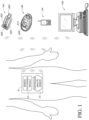
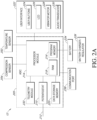
- FIG. 2A is a block diagram illustrating embodiments of the sensor electronics module 12 ( FIG. 1 ).
- the sensor electronics module 12 can include an application-specific integrated circuit (ASIC) 205, a user interface 222, compression sensor 254 and temperature sensor 252.
- ASIC 205 can also be coupled to a communication port 238 and a battery 234.
- FIG. 2A shows an ASIC 205 that includes much of the electronic circuitry, the ASIC 205 may be replaced with one or more of any suitable logic device, such as field programmable gate arrays (FPGA), microprocessors, analog circuitry, or other digital and/or analog circuitry.
- ASIC 205 can include one or more additional features of sensor electronics module 12 discussed elsewhere herein, or one or more features illustrated in FIG. 2A as being part of the ASIC - such as telemetry module 232, potentiostat 210, data storage memory 220 - can be separate from the ASIC.
- a potentiostat 210 is coupled to a glucose sensor via data line 212, for example, in order to receive sensor data from the glucose sensor.
- the potentiostat 210 provides a voltage to the glucose sensor via a data line 212 in order to bias the sensor to enable measurement of a current value indicative of the analyte concentration in the host (also referred to as the analog portion).
- the potentiostat can have one channel or multiple channels (and a corresponding one or multiple data lines 212), depending on the number of working electrodes, for example.
- the potentiostat 210 includes a resistor (not shown) that translates the current into voltage.
- a current to frequency converter is provided that is configured to continuously integrate the measured current, for example, using a charge counting device.
- an A/D converter digitizes the analog signal into "counts" for processing. Accordingly, the resulting raw data stream in counts is directly related to the current measured by the potentiostat 210.
- a processor module 214 is the central control unit that controls the processing of the sensor electronics module 12.
- the processor module 214 is formed as part of a custom chip, such as an ASIC, however a computer system other than an ASIC can be used to process data as described herein, for example a microprocessor can be used for some or all of the sensor electronics module processing.
- the processor module 214 typically provides a program memory 216, which provides semi-permanent storage of data, for example, storing data such as sensor identifier (ID) and programming to process data streams (for example, filtering, calibration, fail-safe checking, and the like).
- the processor additionally can be used for the system's cache memory, for example for temporarily storing recent sensor data.
- the processor module comprises memory storage components such as ROM, RAM, dynamic-RAM, static-RAM, non-static RAM, EEPROM, rewritable ROMs, flash memory, and the like.
- RAM 218 can be used for the system's cache memory, for example for temporarily storing recent sensor data.
- the processor module 214 comprises a digital filter, for example, an IIR or FIR filter, configured to smooth the raw data stream from the A/D converter.
- digital filters are programmed to filter data sampled at a predetermined time interval (also referred to as a sample rate). In some embodiments, such as when the potentiostat 210 is configured to measure the analyte at discrete time intervals, these time intervals determine the sample rate of the digital filter.
- the processor module 214 can be programmed to request a digital value from the integrator at a predetermined time interval, also referred to as the acquisition time.
- the values obtained by the processor module 214 are advantageously averaged over the acquisition time due the continuity of the current measurement. Accordingly, the acquisition time determines the sample rate of the digital filter.
- the processor module 214 may be further configured to generate data packages for transmission to one or more display devices. Furthermore, the processor module 215 may generate data packets for transmission to these outside sources, e.g., via telemetry.
- the data packages may be customizable for each display device, for example, and may include any available data, such as displayable sensor information having customized sensor data and/or transformed sensor data, sensor/sensor electronics module ID code, raw data, filtered data, calibrated data, rate of change information, trend information, error detection or correction, and/or the like.
- a data storage memory 220 is operably connected to the processor module 214 and is configured to store a variety of sensor information.
- the data storage memory stores 1, 3, 4, 5, 6, 7, 8, 9, 10, 11, 12, 13, 14, 15, 20, 30 or more days of continuous analyte sensor data.
- the data storage memory 220 stores sensor information such as raw sensor data (one or more raw analyte concentration values), calibrated data, filtered data, transformed sensor data, and/or any other displayable sensor information.
- sensor electronics module 12 is configured to receive and store contact information in the data storage memory (and/or program memory), including a phone number and/or email address for the sensor's host and/or health care providers for the host (e.g., family member(s), nurse(s), doctor(s), or other health care provider(s)), which enables communication with a contact person (e.g., via phone, pager and/or text messaging in response to an alarm (e.g., a hypoglycemic alarm that has not been responded to by the host)).
- contact information in the data storage memory (and/or program memory)
- a phone number and/or email address for the sensor's host and/or health care providers for the host (e.g., family member(s), nurse(s), doctor(s), or other health care provider(s)), which enables communication with a contact person (e.g., via phone, pager and/or text messaging in response to an alarm (e.g., a hypoglycemic alarm that has not been responded to by the
- user parameters can be programmed into (and/or modified in) the data storage memory (and/or program memory) of the sensor electronics module, via a display device such as a personal computer, personal digital assistant, or the like.
- user parameters include contact information, alert/alarms settings (e.g., thresholds, sounds, volume, and/or the like), calibration information, font size, display preferences, defaults (e.g., screens), and/or the like.
- the sensor electronics module can be configured for direct programming of certain user parameters.
- buttons 224 can allow, for example, toggle, menu selection, option selection, status selection, yes/no response to on-screen questions, a "turn off' function (e.g., for an alarm), a "snooze” function (e.g., for an alarm), a reset, and/or the like.
- the LCD 226 can be provided, for example, to provide the user with visual data output.
- the audio transducer 230 e.g., speaker
- audible signals are differentiated by tone, volume, duty cycle, pattern, duration, and/or the like.
- a telemetry module 232 is operably connected to the processor module 214 and provides the hardware, firmware, and/or software that enable wireless communication between the sensor electronics module 12 and one or more display devices.
- wireless communication technologies that can be implemented in the telemetry module 232 include radio frequency (RF), infrared (IR), Bluetooth, spread spectrum communication, frequency hopping communication, ZigBee, IEEE 802.11/802.16, wireless (e.g., cellular) telecommunication, paging network communication, magnetic induction, satellite data communication, GPRS, ANT, and/or the like.
- the telemetry module comprises a Bluetooth chip.
- Bluetooth technology is implemented in a combination of the telemetry module 232 and the processor module 214.
- the sensor electronics module 12 executes prospective algorithms used to generate transformed sensor data and/or displayable sensor information, including, for example, algorithms that: evaluate a clinical acceptability of reference and/or sensor data, evaluate calibration data for best calibration based on inclusion criteria, evaluate a quality of the calibration, compare estimated analyte values with time corresponding measured analyte values, analyze a variation of estimated analyte values, evaluate a stability of the sensor and/or sensor data, detect signal artifacts (noise), replace signal artifacts, determine a rate of change and/or trend of the sensor data, perform dynamic and intelligent analyte value estimation, perform diagnostics on the sensor and/or sensor data, set modes of operation, evaluate the data for aberrancies, and/or the like, which are described in more detail in U.S.
- Patent No. 7,310,544 U.S. Patent No. 6,931,327 , U.S. Patent Publication No. US-2005-0043598-A1 , U.S. Patent Publication No. US-2007-0032706-A1 , U.S. Patent Publication No. US-2007-0016381-A1 , U.S. Patent Publication No. US-2008-0033254-A1 , U.S. Patent Publication No. US-2005-0203360-A1 , U.S. Patent Publication No. US-2005-0154271-Al , U.S. Patent Publication No. US-2005-0192557-Al , U.S. Patent Publication No.
- the sensor electronics module 12 is configured to store the transformed sensor data (e.g., values, trend information) and to communicate the displayable sensor information to a plurality of different display devices.
- the display devices are "dummy" devices, namely, they are configured to display the displayable sensor information as received from the sensor electronics module 12, without any additional sensor data processing.
- the base 242 is formed at least partially from a flexible material, which is believed to provide numerous advantages over conventional transcutaneous sensors, which, unfortunately, can suffer from motion-related artifacts associated with the host's movement when the host is using the device.
- the mounting unit 240 and/or sensor electronics module 12 can be located over the sensor insertion site to protect the site and/or provide a minimal footprint (utilization of surface area of the host's skin).
- a detachable connection between the mounting unit 240 and sensor electronics module 12 is provided, which enables improved manufacturability, namely, the relatively inexpensive mounting unit 240 can be disposed of when replacing the sensor system after its usable life, while the relatively more expensive sensor electronics module 12 can be reusable with multiple sensor systems.
- the sensor electronics module 12 is configured with signal processing (programming), for example, configured to filter, calibrate and/or other algorithms useful for calibration and/or display of sensor information.
- signal processing for example, configured to filter, calibrate and/or other algorithms useful for calibration and/or display of sensor information.
- an integral (non-detachable) sensor electronics module can be configured.
- the contacts 244 are mounted on or in a subassembly hereinafter referred to as a contact subassembly 246 configured to fit within the base 242 of the mounting unit 240 and a hinge 248 that allows the contact subassembly 246 to pivot between a first position (for insertion) and a second position (for use) relative to the mounting unit 240.
- a contact subassembly 246 configured to fit within the base 242 of the mounting unit 240 and a hinge 248 that allows the contact subassembly 246 to pivot between a first position (for insertion) and a second position (for use) relative to the mounting unit 240.
- the mounting unit 240 is provided with an adhesive pad 250, disposed on the mounting unit's back surface and including a releasable backing layer.
- an adhesive pad 240 can be placed over some or all of the sensor system 8 after sensor insertion is complete to ensure adhesion, and optionally to ensure an airtight seal or watertight seal around the wound exit-site (or sensor insertion site) (not shown).
- Appropriate adhesive pads can be chosen and designed to stretch, elongate, conform to, and/or aerate the region (e.g., host's skin).
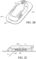
- FIGS. 2B and 2C are described in more detail with reference to U.S. Patent No. 7,310,544 .
- configurations and arrangements that provide water resistant, waterproof, and/or hermetically sealed properties are provided associated with the mounting unit/sensor electronics module embodiments described herein.
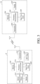
- the sensor system 8 may further include a memory 318 (also designated 220 in FIG. 2A ) and a real time clock 320 (part of item 12 in FIG. 1 ) for storing and tracking sensor data.
- Wireless communication protocols may be used to transmit and receive data between the sensor system 8 and the display device 14.
- the wireless protocol used may be designed for use in a wireless sensor network that is optimized for periodic and small data transmissions (that may be transmitted at low rates if necessary) to and from multiple devices in a close range (e.g., a personal area network (PAN)).
- PAN personal area network
- the protocol may be optimized for periodic data transfers where transceivers may be configured to transmit data for short intervals and then enter low power modes for long intervals.
- the protocol may have low overhead requirements both for normal data transmissions and for initially setting up communication channels (e.g., by reducing header overhead) to reduce power consumption.
- burst broadcasting schemes e.g., one way communication
- This may eliminate overhead required for acknowledgement signals and allow for periodic transmissions that consume little power.
- the display device 14 may be used for alerting and providing sensor information to a user, and may include a processor 330 for processing and managing sensor data.
- the display device 14 may include a display 332, a memory 334, and a real time clock 336 for displaying, storing and tracking sensor data respectively.
- the display device 14 may further include a transceiver 338 for receiving sensor data and for sending requests, instructions, and data to the sensor system 8.
- the transceiver 338 may further employ a communication protocol.
- the sensor session as defined above may correspond to the life of the sensor 312 (e.g., 7-30 days).
- a sensor electronic module When a sensor electronic module is used for the first time (or reactivated once a battery has been replaced in some cases), it may be connected to a sensor 312 and a sensor session may be established.
- a new sensor session may be established.
- the new sensor session may be initiated through a process completed using a display device 14 and the process may be triggered by notifications of a new sensor via the communication between the sensor electronics module and the display device 14 that may be persistent across sensor sessions.
- the analyte sensor system 8 gathers analyte data from the sensor 312 that it periodically sends to the display device 14. Data points are gathered and transmitted over the life of the sensor (e.g., 1, 3, 7, 10, 15,30 or more days). New measurements may need to be transmitted often enough to adequately monitor glucose levels. Rather than having the transmission and receiving circuitry of each of the sensor system 8 and display device 14 continuously communicating, the analyte sensor system 8 and display device 14 may regularly and periodically establish a communication channel between them. Thus, sensor system 8 can communicate via wireless transmission with display device 14 at predetermined time intervals.
- the duration of the predetermined time interval can be selected to be long enough so that the sensor system 8 does not consume too much power by transmitting data more frequently than needed, yet frequent enough to provide substantially real-time sensor information (e.g., measured glucose values) to the display device 14 for output (e.g., display) to a user. While the predetermined time interval is every five minutes in some embodiments, it is appreciated that this time interval can be varied to be any desired length of time. These predetermined time intervals and associated communications are discussed in more detail with respect to FIG. 9 , below.
- sensor system 8 performs a number of tasks, each of which consume a fair amount of power. Over the life of sensor system 8, power consumption may serve as one of the biggest limitations to completing more and more complex tasks, such as increased data transfer and updates to display device 14. Furthermore, should it be desirable to further decrease the size of sensor system 8, the size of the battery may also need to be reduced, likely resulting in also reducing the life of sensor system 8. Consequently, systems and methods for achieving power savings in conjunction with sensor system 8 are highly desirable.
- sensor system 8 may utilize a low power measurement circuit that is capable of switching between a measurement mode and a low power mode to conserve power usage.
- measurement circuitry can be powered and electrically coupled to sensor electrodes to take sensor measurements.
- a charging circuit can be powered and electrically coupled to a capacitive circuit to charge the capacitive circuit.
- the circuit can enter the low power mode.
- the measurement circuitry can be decoupled from the sensor electrodes and powered down, and the charging circuitry can be decoupled from the capacitive circuit and powered down.
- the capacitive circuit can be electrically coupled to the sensor electrode or sensor electrodes to maintain a voltage across the electrode(s).
- measurement circuitry can be powered down in between taking measurements to reduce power consumption, but yet a voltage can be maintained across the sensor electrodes through the use of capacitive circuit. Maintaining a voltage across the sensor electrodes while measurement circuitry is powered down may be desired.
- Example low power measurement circuits are described in U.S. Patent Publication No. 20120078071 .
- circuitry that detects any extra current flowing within sensor system 8 may be useful in ensuring that system 8 is operating efficiently. For example, measuring any excess current flowing within the sensor system 8 when it is in a low power or sleep mode would be desirable. However, to have a measurement means being actively powered to measure the excess current while the system 8 is in sleep mode could be counterproductive, depending upon the implementation, as it could consume power to monitor possible excess current. Furthermore, sending information related to the excess current while the system 8 is in sleep mode may cause the system 8 to wake up prematurely, which could also be undesirable.
- a means for monitoring the current when sensor system 8 is in storage or sleep mode that does not need to be actively powered would be desirable in some implementations.
- a measurement means for detecting excess current that does not cause the system 8 to prematurely wake up from sleep mode to receive the measurement information would be desirable in some implementations.
- Such measurement means may be implemented in, for example, a separate circuit for measuring current when system 8 is in sleep mode (hereinafter referred to as "sleep current").
- Low power circuit 400 can power down measurement circuitry 402 from an active measuring state to a low power inactive sleep state, where the sleep current is measured through the use of sleep current circuitry 408.
- Control circuitry 414 can be configured to provide a sleep pulse signal to sleep current circuitry 408 when in the inactive sleep state.
- the sleep pulse signal is simply a pulse that switches the sleep current circuitry 408 into an on mode, and does not provide any power for an ongoing period of time.
- control circuitry 414 may include a timer that places low power circuit 400 in sleep mode for 30 seconds. During this time, a sleep pulse signal (e.g., as a single pulse) flows from control circuitry 414 to sleep current circuitry 408 to switch the sleep current circuitry 408 on. Sleep current circuitry 408 may charge a capacitor, where the voltage across the capacitor correlates with the sleep pulse signal provided to sleep current circuitry 408. After the sleep mode has terminated, an output voltage for the capacitor can be determined by sleep current circuitry 408. This output voltage may be correlated with a characteristic of the sleep pulse signal (e.g., amperes or total charge for the sleep pulse signal) to differentiate any charge in the capacitor resulting from the sleep pulse signal from any sleep current. An error or fault can be identified if the output voltage is above or below pre-determined thresholds. For example, an error message can be displayed to a user if the output voltage is above or below pre-determined thresholds.
- a characteristic of the sleep pulse signal e.g., amperes or total
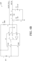
- FIG. 4B shows an example of sleep mode circuitry 408 for monitoring current flowing within sensor system 8 when sensor system 8 is in a reduced power or sleep mode.
- sleep mode circuitry 408 captures any current resulting from the sleep pulse signal as well as any sleep current as a charge on a capacitor from a large current sense resistor that may be automatically switched out of the circuit by hardware (e.g., internal to a processor) when the system 8 wakes or powers up. The system 8 can then immediately read the charge on the capacitor to determine if the total current reading (e.g., current attributable to sleep pulse signal and the sleep current) is within an acceptable range.
- the total current reading e.g., current attributable to sleep pulse signal and the sleep current
- sleep current circuit 408 may include an analog switch U1 powered by a battery BT1.
- a first resistor R1 may maintain switch U1 in state S2, connecting battery BT1 to system ground GND.
- the sleep pulse signal may simply change the state of sleep current circuit 408 into an active measuring or on mode.
- the sleep pulse signal may comprise a single pulse, being almost instantaneous and having no lasting duration (e.g., a millisecond or more).
- the sleep pulse signal may result in some charge in circuit 408. This resultant charge may be subtracted from the total measured charge to determine the sleep current or taken into account when comparing the total charge to a threshold.
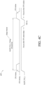
- FIG. 4C shows a sleep timing diagram 450 with a sleep interval set for 30 seconds.
- software may be used to set up a timer that will wake the processor from its sleep mode.
- the processor is briefly active when entering sleep mode to set the timer (shown in the time series "CPU Active" in FIG. 4C ).
- a sleep pulse signal is generated (e.g., from a processor) that goes low for a short time (e.g., about 100 ms) before wake up occurs, switching battery BT1 to state S1.
- the sleep pulse signal is shown in the time series "SLEEP_PLS_L" in FIG. 4C .
- the processor becomes active again at the end of the 30-second sleep interval.
- capacitor C1 has a voltage that correlates to the sleep pulse signal (due to resistor R2). This voltage may be transferred through resistor R2 to capacitor C1. It will be appreciated that the sleep pulse signal is applied long enough to charge capacitor C1 to the level of resistor R2.
- state S2 is re-entered, while preserving the voltage at capacitor C1.
- software may use an ADC channel (shown in FIG. 4B as ADC_IN) to read the charge on capacitor C1 before it is discharged through resistors R2 and R3.
- ADC_IN ADC channel
- the charge at capacitor C1 due to the current received from battery BT1 via resistor R1 may be accounted for when correlating the sleep pulse signal with the charge on capacitor C1 (e.g., an amount of charge subtracted due to current from battery BT1).
- sensor system 8 may spend a substantial amount of time sleeping or in a lower power mode, if the output voltage on the capacitor is higher than expected (e.g., greater than an amount expected from the sleep pulse signal, the internal battery of the sleep current circuit, or combination thereof), battery life may be significantly shortened due to unwanted sleep currents in the system.
- This present circuit allows sensor system 8 to verify correct operation and normal battery drain when it is sleep mode. If a fault is indicated, diagnostics or remedial action can occur.
- the sensor system may monitor and record possible technical issues associated with the sensor system 8. The technical issues may be recorder in a technical support log file stored in memory of the sensor system
- leakage current refers to any current that flows when the ideal current is zero and the system 8 is an active measurement mode (e.g., as opposed to standby, disabled, or "sleep" mode, as described above). These devices can draw one or two microamperes while in their quiescent state compared to hundreds or thousands of milliamperes while in full operation. These leakage currents are becoming a significant factor to portable device manufacturers because of their undesirable effect on e.g., battery run time.
- sensor data may comprise digital data in "counts” converted by an A/D converter from an analog signal (e.g., voltage or amps).
- Leakage current may affect the sensor data reading directly by showing an increase in counts (e.g., a high leakage current will produce an increased value for the converted counts).
- the leakage current may change as a result of the internal temperature of various hardware components (such as illustrated in FIG. 2A ) changing.
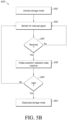
- the leakage current may be determined by: (1) determining if the internal temperature of one or more hardware components has changed, and (2) if the internal temperature of one or more hardware components has changed, measuring the leakage current.
- the leakage current may be measured by creating an open circuit at or near the location where leakage is expected. It should be appreciated that any circuit capable of detecting leakage current, as is known by one of skill in the art, may be implemented by the present disclosure.
- a leakage current is detected for sensor system 8 using a leak detection circuit in communication with the sensor system 8.
- the leakage current may be received by the sensor system (e.g., via a processor). Thereafter, an adjustment may be performed on or more sensor signals using the leakage current. For example, the adjustment to the sensor signal may be subtracting the leakage current from a sensor signal. In other words, the leakage current may be "auto-zeroed" out from the sensor signal.
- the adjusted sensor signal may be provided to a user in a desirable format (e.g. as sensor count data).
- a storage mode can be activated with a command at manufacturing that initiates a routine implemented by software stored in memory, for example, to power off select circuitry in sensor electronics module 12 and put processor module 414 into a low power mode (e.g., sleep mode).
- Sensor electronics module 12 can then be placed in a package that places sensor electronics module 12 next to a storage magnet, which keeps it in storage mode until sensor electronics module 12 is pulled away from the magnet by a user.
- the storage magnet can be incorporated into the packaging directly next to where the sensor electronics module 12 is held, for example.
- pulling a magnet away from sensor electronics module switches sensor electronics module 12 out of a storage mode and into a normal operation mode.
- pulling the sensor electronics module 12 away from the magnet can trigger an interrupt line, which initiates an interrupt routine performed by software stored in the electronics module 12.
- the interrupt routine can initiate a state machine implemented using sleep timer interrupts which check periodically across multiple intervals, for a predetermined amount of time, such as five minutes, to validate that the sensor electronics module 12 has indeed been moved away from the magnet.
- the state machine puts sensor electronics module 12 in normal operation mode by, for example, pulling processor 314 out of low power mode, and restoring or providing power to other circuitry of sensor electronic module 12.
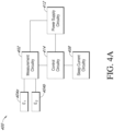
- FIG. 5A is a simplified block diagram of an embodiment of sensor electronics module 12 with a low power storage mode feature.
- FIG. 5A only illustrates select components of a sensor electronics module 12 and it is understood that further components can be incorporated into sensor electronics module 12, such as any components discussed above with reference to FIG. 5A .
- a sensor kit can also be provided that includes one or more sensor electronics modules 12 and a plurality of sensors 10, which include low power mode storage feature(s). Such sensor kits are described in further detail in U.S. Patent Publication No. 20120078071 .
- sensor electronics module 12 includes a switch 520 configured to switch between a first state (e.g., closed state) when a force is applied to the switch and second state (e.g., open state) when the force is removed or sufficiently diminished.
- the applied force is a magnetic field, generated by any suitable means (e.g., mechanical or electrical).
- Switch 520 is operatively connected to system processor 514, which is in turn operatively connected to ASIC 524 via FET switch 522.
- Telemetry module 532 is also operatively connected to microprocessor 514.
- switch 520 is a reed switch. In other embodiments, switch 520 is a Hall-effect switch.
- switch 520 When switch 520 is a reed switch, it includes one or more pairs of magnetizable, flexible, metal reeds whose end portions are separated by a small gap when the switch is open. The reeds may be hermetically sealed in opposite ends of a tubular glass envelope. A magnetic field (from an electromagnet or a permanent magnet) will cause the reeds to come together, thus completing an electrical circuit. Good electrical contact may be assured by plating a thin layer of non-ferrous precious metal such as low-resistivity silver over flat contact portions of the reeds.
- switch 520 When switch 520 is a Hall-effect switch, it includes a transducer that varies its output voltage in response to a magnetic field.
- the Hall-effect switch is mounted onto a PCB, similar to other components of FIG. 5A .
- Hall-effect switch may be triggered by an external magnet, such as magnet 526 described below.
- a Hall-effect switch may be preferable to other switch types such as a reed switch, which may be sensitive to vibration and shock and to a light switch, since not optical window is required for the Hall-effect switch.
- the sensor electronics module 12 includes a light-sensitive sensor that triggers the switch between the first state and the second state. That is, the light sensitive-sensor takes the sensor electronics module out of a storage mode when the light-sensitive sensor is exposed to light in accordance with some embodiments.
- sensor electronics module 12 can be placed in a low power, storage mode during manufacture, shipment and storage so the sensor electronics module consumes little power.
- a light-sensitive sensor can be included in sensor electronics module 12 that is shielded from light by a protective cover and the sensor electronics module placed in a storage mode in a similar manner as described above. Thus, during manufacture, shipment and storage of sensor electronics module 12, the sensor electronics module can be in the storage mode.
- 2007-0066873-A1 U.S. Patent Publication No. 2007-0173709-A1 ; U.S. Patent Publication No. 2007-0173710-A1 ; U.S. Patent Publication No. 2007-0208245-A1 ; U.S. Patent Publication No. 2007-0208246-A1 ; U.S. Patent Publication No. 2007-0232879-A1 ; U.S. Patent Publication No. 2008-0045824-A1 ; U.S. Patent Publication No. 2008-0083617-A1 ; U.S. Patent Publication No. 2008-0086044-A1 ; U.S. Patent Publication No. 2008-0108942-A1 ; U.S.
- Patent Publication No. 2008-0119703-A1 U.S. Patent Publication No. 2008-0119704-A1 ; U.S. Patent Publication No. 2008-0119706-A1 ; U.S. Patent Publication No. 2008-0183061-A1 ; U.S. Patent Publication No. 2008-0183399-A1 ; U.S. Patent Publication No. 2008-0188731-A1 ; U.S. Patent Publication No. 2008-0189051-A1 ; U.S. Patent Publication No. 2008-0194938-A1 ; U.S. Patent Publication No. 2008-0197024-A1 ; U.S. Patent Publication No. 2008-0200788-A1 ; U.S. Patent Publication No.
- Patent Publication No. 2009-0287074-A1 U.S. Patent Publication No. 2009-0299155-A1 ; U.S. Patent Publication No. 2009-0299156-A1 ; U.S. Patent Publication No. 2009-0299162-A1 ; U.S. Patent Publication No. 2010-0010331-A1 ; U.S. Patent Publication No. 2010-0010332-A1 ; U.S. Patent Publication No. 2010-0016687-A1 ; U.S. Patent Publication No. 2010-0016698-A1 ; U.S. Patent Publication No. 2010-0030484-A1 ; U.S. Patent Publication No. 2010-0036215-A1 ; U.S.
- Patent Publication No. 2010-0036225-A1 U.S. Patent Publication No. 2010-0041971-A1 ; U.S. Patent Publication No. 2010-0045465-A1 ; U.S. Patent Publication No. 2010-0049024-A1 ; U.S. Patent Publication No. 2010-0076283-A1 ; U.S. Patent Publication No. 2010-0081908-A1 ; U.S. Patent Publication No. 2010-0081910-A1 ; U.S. Patent Publication No. 2010-0087724-A1 ; U.S. Patent Publication No. 2010-0096259-A1 ; U.S. Patent Publication No.
- Patent Publication No. 2012-0186581-A1 U.S. Patent Publication No. 2012-0190953-A1 ; U.S. Patent Publication No. 2012-0191063-A1 ; U.S. Patent Publication No. 2012-0203467-A1 ; U.S. Patent Publication No. 2012-0209098-A1 ; U.S. Patent Publication No. 2012-0215086-A1 ; U.S. Patent Publication No. 2012-0215087-A1 ; U.S. Patent Publication No. 2012-0215201-A1 ; U.S. Patent Publication No. 2012-0215461-A1 ; U.S. Patent Publication No. 2012-0215462-A1 ; U.S.
- Patent Publication No. 2012-0215496-A1 U.S. Patent Publication No. 2012-0220979-A1 ; U.S. Patent Publication No. 2012-0226121-A1 ; U.S. Patent Publication No. 2012-0228134-A1 ; U.S. Patent Publication No. 2012-0238852-A1 ; U.S. Patent Publication No. 2012-0245448-A1 ; U.S. Patent Publication No. 2012-0245855-A1 ; U.S. Patent Publication No. 2012-0255875-A1 ; U.S. Patent Publication No. 2012-0258748-A1 ; U.S. Patent Publication No.
- the term 'including' should be read to mean 'including, without limitation,' 'including but not limited to,' or the like;
- the term 'comprising' as used herein is synonymous with 'including,' 'containing,' or 'characterized by,' and is inclusive or open-ended and does not exclude additional, unrecited elements or method steps;
- the term 'having' should be interpreted as 'having at least;
- the term 'includes' should be interpreted as 'includes but is not limited to;
- the term 'example' is used to provide exemplary instances of the item in discussion, not an exhaustive or limiting list thereof; adjectives such as 'known', 'normal', 'standard', and terms of similar meaning should not be construed as limiting the item described to a given time period or to an item available as of a given time, but instead should be read to encompass known, normal, or standard technologies that may be available or known now or at any time in the future; and use
- a group of items linked with the conjunction 'and' should not be read as requiring that each and every one of those items be present in the grouping, but rather should be read as 'and/or' unless expressly stated otherwise.
- a group of items linked with the conjunction 'or' should not be read as requiring mutual exclusivity among that group, but rather should be read as 'and/or' unless expressly stated otherwise.
Landscapes
- Health & Medical Sciences (AREA)
- Engineering & Computer Science (AREA)
- Life Sciences & Earth Sciences (AREA)
- Biomedical Technology (AREA)
- Public Health (AREA)
- Medical Informatics (AREA)
- General Health & Medical Sciences (AREA)
- Physics & Mathematics (AREA)
- Pathology (AREA)
- Heart & Thoracic Surgery (AREA)
- Molecular Biology (AREA)
- Surgery (AREA)
- Animal Behavior & Ethology (AREA)
- Biophysics (AREA)
- Veterinary Medicine (AREA)
- Epidemiology (AREA)
- Primary Health Care (AREA)
- General Business, Economics & Management (AREA)
- Business, Economics & Management (AREA)
- Optics & Photonics (AREA)
- Chemical & Material Sciences (AREA)
- Computer Networks & Wireless Communication (AREA)
- General Chemical & Material Sciences (AREA)
- Chemical Kinetics & Catalysis (AREA)
- Bioinformatics & Cheminformatics (AREA)
- Medicinal Chemistry (AREA)
- Emergency Medicine (AREA)
- Nuclear Medicine, Radiotherapy & Molecular Imaging (AREA)
- Radiology & Medical Imaging (AREA)
- Databases & Information Systems (AREA)
- Data Mining & Analysis (AREA)
- Measurement Of The Respiration, Hearing Ability, Form, And Blood Characteristics Of Living Organisms (AREA)
- Radar Systems Or Details Thereof (AREA)
Claims (11)
- System zur kontinuierlichen Messung eines Analyten in einem Wirt, wobei das System Folgendes einschließt:einen kontinuierlichen Analyt-Sensor, der so konfiguriert ist, dass er kontinuierlich eine Konzentration des Analyten in dem Wirt misst;ein Sensor-Elektronikmodul, das während der Verwendung des Sensors physisch mit dem kontinuierlichen Analyt-Sensor verbunden ist, wobei das Sensor-Elektronikmodul eine Elektronik einschließt, die so konfiguriert ist, dass sie einen Datenstrom verarbeitet, der mit einer von dem kontinuierlichen Analyt-Sensor gemessenen Analytkonzentration verbunden ist, um Sensorinformationen zu erzeugen, die anzeigbare Sensorinformationen einschließen, und um die anzeigbaren Sensorinformationen unter Verwendung der drahtlosen Bluetooth-Technologie an eine Anzeigevorrichtung zu übertragen; undeine Anzeigevorrichtung, die so konfiguriert ist, dass sie die anzeigbaren Sensorinformationen, die von dem Sensor-Elektronikmodul übertragen wurden, anzeigt und die anzeigbaren Sensorinformationen zur Alarmierung verwendet;wobei das Sensor-Elektronikmodul so konfiguriert ist, dass es:eine NFC-Übertragung von der Anzeigevorrichtung empfängt; undnach dem Empfang der NFC-Übertragung aus einem Energiesparmodus aufwacht und wartet, bis der Sensor in vivo äquilibriert ist, um sicherzustellen, dass der Sensor stabil ist, bevor die anzeigbaren Sensorinformationen an die Anzeigevorrichtung übertragen werden.
- System nach Anspruch 1, wobei das Sensor-Elektronikmodul in den kontinuierlichen Analyt-Sensor integriert ist.
- System nach Anspruch 1 oder 2, wobei das Sensor-Elektronikmodul so konfiguriert ist, dass es die anzeigbaren Sensorinformationen periodisch an die Anzeigevorrichtung überträgt.
- System nach Anspruch 3, wobei das Sensor-Elektronikmodul so konfiguriert ist, dass es die periodische Übertragung der anzeigbaren Sensorinformationen an die Anzeigevorrichtung in vorgegebenen Zeitintervallen durchführt.
- System nach einem vorstehenden Anspruch, wobei die NFC-Übertragung von der Anzeigevorrichtung ein vom Benutzer initiierter NFC-Weckruf ist, um das Sensor-Elektronikmodul aus dem Energiesparmodus in einen Betriebsmodus mit höherer Leistung zu versetzen.
- System nach einem der Ansprüche 5, wobei die Anzeigevorrichtung so konfiguriert ist, dass sie Identifikationsinformationen und einen Befehl zum Aufwachen des Sensor-Elektronikmoduls aus dem Energiesparmodus überträgt.
- System nach Anspruch 6, wobei die Identifikationsinformationen spezifisch für das Sensorsystem sind.
- System nach einem vorstehenden Anspruch, wobei die Anzeigevorrichtung ein Smartphone ist.
- System nach einem vorstehenden Anspruch, wobei das Sensor-Elektronikmodul ein NFC-Tag einschließt und die Anzeigevorrichtung so konfiguriert ist, dass sie dem NFC-Tag Energie zuführt, indem sie ein HF-Feld erzeugt.
- System nach einem vorstehenden Anspruch, wobei das Sensor-Elektronikmodul ein NFC-Tag einschließt und die Anzeigevorrichtung so konfiguriert ist, dass sie eine Sender-ID aus dem NFC-Tag liest, um das Sensor-Elektronikmodul mit einer Empfangsvorrichtung zu paaren.
- Verfahren zur kontinuierlichen Messung eines Analyten in einem Wirt unter Verwendung eines Systems, das einen kontinuierlichen Analyt-Sensor, ein Sensor-Elektronikmodul einschließlich Elektronik und eine Anzeigevorrichtung umfasst, wobei das Sensor-Elektronikmodul während der Verwendung physisch mit dem kontinuierlichen Analyt-Sensor verbunden ist, wobei das Verfahren umfasst:der kontinuierliche Analyt-Sensor misst kontinuierlich eine Konzentration des Analyten in dem Wirt,das Sensor-Elektronikmodul verarbeitet einen Datenstrom, der mit einer von dem kontinuierlichen Analyt-Sensor gemessenen Analytkonzentration verbunden ist, um Sensorinformationen zu erzeugen, die anzeigbare Sensorinformationen einschließen, und überträgt die anzeigbaren Sensorinformationen unter Verwendung der drahtlosen Bluetooth-Technologie an die Anzeigevorrichtung; unddie Anzeigevorrichtung zeigt die anzeigbaren Sensorinformationen an, die von dem Sensor-Elektronikmodul übertragen wurden, und verwendet die anzeigbaren Sensorinformationen zur Alarmierung;wobei das Sensor-Elektronikmodul:eine NFC-Übertragung von der Anzeigevorrichtung empfängt; undnach dem Empfang der NFC-Übertragung aus einem Energiesparmodus aufwacht und wartet, bis der Sensor in vivo äquilibriert ist, um sicherzustellen, dass der Sensor stabil ist, bevor die anzeigbaren Sensorinformationen an die Anzeigevorrichtung übertragen werden.
Applications Claiming Priority (6)
| Application Number | Priority Date | Filing Date | Title |
|---|---|---|---|
| US13/830,330 US9788354B2 (en) | 2013-03-14 | 2013-03-14 | Systems and methods for processing and transmitting sensor data |
| US13/827,577 US9445445B2 (en) | 2013-03-14 | 2013-03-14 | Systems and methods for processing and transmitting sensor data |
| US14/142,677 US9931036B2 (en) | 2013-03-14 | 2013-12-27 | Systems and methods for processing and transmitting sensor data |
| PCT/US2014/016111 WO2014158405A2 (en) | 2013-03-14 | 2014-02-12 | Systems and methods for processing and transmitting sensor data |
| EP18175412.8A EP3401818B1 (de) | 2013-03-14 | 2014-02-12 | Systeme und verfahren zur verarbeitung und übertragung von sensordaten |
| EP14708172.3A EP2973082B1 (de) | 2013-03-14 | 2014-02-12 | Systeme und verfahren zur verarbeitung und übertragung von sensordaten |
Related Parent Applications (3)
| Application Number | Title | Priority Date | Filing Date |
|---|---|---|---|
| EP18175412.8A Division EP3401818B1 (de) | 2013-03-14 | 2014-02-12 | Systeme und verfahren zur verarbeitung und übertragung von sensordaten |
| EP18175412.8A Division-Into EP3401818B1 (de) | 2013-03-14 | 2014-02-12 | Systeme und verfahren zur verarbeitung und übertragung von sensordaten |
| EP14708172.3A Division EP2973082B1 (de) | 2013-03-14 | 2014-02-12 | Systeme und verfahren zur verarbeitung und übertragung von sensordaten |
Publications (2)
| Publication Number | Publication Date |
|---|---|
| EP4235684A1 EP4235684A1 (de) | 2023-08-30 |
| EP4235684B1 true EP4235684B1 (de) | 2025-03-26 |
Family
ID=51625593
Family Applications (5)
| Application Number | Title | Priority Date | Filing Date |
|---|---|---|---|
| EP23173573.9A Active EP4235684B1 (de) | 2013-03-14 | 2014-02-12 | Systeme und verfahren zur verarbeitung und übertragung von sensordaten |
| EP23173577.0A Active EP4220654B1 (de) | 2013-03-14 | 2014-02-12 | Systeme und verfahren zur verarbeitung und übertragung von sensordaten |
| EP14708172.3A Revoked EP2973082B1 (de) | 2013-03-14 | 2014-02-12 | Systeme und verfahren zur verarbeitung und übertragung von sensordaten |
| EP18175412.8A Active EP3401818B1 (de) | 2013-03-14 | 2014-02-12 | Systeme und verfahren zur verarbeitung und übertragung von sensordaten |
| EP25161231.3A Pending EP4542574A3 (de) | 2013-03-14 | 2014-02-12 | Systeme und verfahren zur verarbeitung und übertragung von sensordaten |
Family Applications After (4)
| Application Number | Title | Priority Date | Filing Date |
|---|---|---|---|
| EP23173577.0A Active EP4220654B1 (de) | 2013-03-14 | 2014-02-12 | Systeme und verfahren zur verarbeitung und übertragung von sensordaten |
| EP14708172.3A Revoked EP2973082B1 (de) | 2013-03-14 | 2014-02-12 | Systeme und verfahren zur verarbeitung und übertragung von sensordaten |
| EP18175412.8A Active EP3401818B1 (de) | 2013-03-14 | 2014-02-12 | Systeme und verfahren zur verarbeitung und übertragung von sensordaten |
| EP25161231.3A Pending EP4542574A3 (de) | 2013-03-14 | 2014-02-12 | Systeme und verfahren zur verarbeitung und übertragung von sensordaten |
Country Status (4)
| Country | Link |
|---|---|
| US (2) | US12125588B2 (de) |
| EP (5) | EP4235684B1 (de) |
| ES (1) | ES2969238T3 (de) |
| WO (1) | WO2014158405A2 (de) |
Families Citing this family (24)
| Publication number | Priority date | Publication date | Assignee | Title |
|---|---|---|---|---|
| US8456301B2 (en) | 2007-05-08 | 2013-06-04 | Abbott Diabetes Care Inc. | Analyte monitoring system and methods |
| US8160900B2 (en) | 2007-06-29 | 2012-04-17 | Abbott Diabetes Care Inc. | Analyte monitoring and management device and method to analyze the frequency of user interaction with the device |
| EP2473963A4 (de) | 2009-08-31 | 2014-01-08 | Abbott Diabetes Care Inc | Medizinische geräte und verfahren |
| CN109222991B (zh) * | 2013-04-30 | 2022-04-19 | 雅培糖尿病护理公司 | 在活体分析物监测环境中供应电力的方法以及监测系统 |
| EP4564706A3 (de) * | 2015-12-28 | 2025-10-08 | DexCom, Inc. | Intelligente drahtlose kommunikation zur kontinuierlichen analytüberwachung |
| PL3261357T3 (pl) | 2016-06-23 | 2019-05-31 | Hoffmann La Roche | Sposób bezprzewodowej transmisji danych między układem czujnika a odbiornikiem, układ bezprzewodowej transmisji danych i produkt-programu komputerowego |
| CA3029378C (en) | 2016-07-20 | 2022-06-07 | Dexcom, Inc. | System and method for wireless communication of glucose data |
| US11032855B2 (en) | 2016-10-18 | 2021-06-08 | Dexcom, Inc. | System and method for communication of analyte data |
| DE202018006591U1 (de) | 2017-08-18 | 2021-07-21 | Abbott Diabetes Care, Inc. | Systeme und Vorrichtungen betreffend die individualisierte Kalibrierung und/oder Herstellung von medizinischen Vorrichtungen |
| CN111727480A (zh) * | 2017-12-21 | 2020-09-29 | 赛诺菲 | 便携式医疗存储器 |
| US10763920B2 (en) | 2018-05-23 | 2020-09-01 | Infineon Technologies Ag | Multipolymer sensor array utilizing NFC |
| US11303632B1 (en) * | 2018-06-08 | 2022-04-12 | Wells Fargo Bank, N.A. | Two-way authentication system and method |
| US12335342B2 (en) | 2020-07-21 | 2025-06-17 | Abbott Diabetes Care Inc. | Transmitting analyte data using low-power instruction sets |
| FR3116168B1 (fr) * | 2020-11-12 | 2023-05-12 | St Microelectronics Rousset | Calibration d’une durée d’activation d’un circuit |
| EP4271271A4 (de) | 2020-12-31 | 2025-02-26 | Abbott Diabetes Care, Inc. | Eingebettete systeme in medizinischen überwachungssystemen |
| WO2023003920A1 (en) | 2021-07-21 | 2023-01-26 | Abbott Diabetes Care Inc. | Over-the-air programming of sensing devices |
| EP4402587A2 (de) | 2021-09-15 | 2024-07-24 | Abbott Diabetes Care, Inc. | Modulares analytkonnektivitätssystem für erweiterbare kommunikation mit verschiedenen arten von physiologischen sensoren |
| US20240389890A1 (en) * | 2021-09-27 | 2024-11-28 | Medtrum Technologies Inc. | Analyte detection system |
| WO2023055914A1 (en) | 2021-09-29 | 2023-04-06 | Abbott Diabetes Care Inc. | Mobile application updates for analyte data receiving devices |
| EP4476735A1 (de) * | 2022-02-10 | 2024-12-18 | Medtronic, Inc. | Erzeugung eines mesh-netzwerks als reaktion auf ein medizinisches ereignis |
| CA3260707A1 (en) | 2022-07-05 | 2024-01-11 | Biolinq Incorporated | SENSOR ASSEMBLY OF A CONTINUOUS ANALYTE MONITORING DEVICE BASED ON A MICRO-NECK ARCH |
| CN117598698B (zh) * | 2023-10-20 | 2024-09-10 | 深圳列拓科技有限公司 | 一种低功耗动态血糖监测处理装置、系统及方法 |
| CN119830930B (zh) * | 2024-02-06 | 2026-03-24 | 支付宝(杭州)数字服务技术有限公司 | 一种协助读卡器实现寻卡的方法、寻卡方法及nfc标签 |
| WO2026041984A1 (en) * | 2024-08-20 | 2026-02-26 | Cilag Gmbh International | Controlling patient monitoring devices |
Family Cites Families (256)
| Publication number | Priority date | Publication date | Assignee | Title |
|---|---|---|---|---|
| US612939A (en) | 1898-10-25 | Freeman r | ||
| US2770898A (en) | 1952-02-09 | 1956-11-20 | Hopp Press Inc | Card holder |
| US4757022A (en) | 1986-04-15 | 1988-07-12 | Markwell Medical Institute, Inc. | Biological fluid measuring device |
| US4994167A (en) | 1986-04-15 | 1991-02-19 | Markwell Medical Institute, Inc. | Biological fluid measuring device |
| US5767791A (en) * | 1995-11-13 | 1998-06-16 | Vitalcom | Low-power circuit and method for providing rapid frequency lock in a wireless communications device |
| US6862465B2 (en) | 1997-03-04 | 2005-03-01 | Dexcom, Inc. | Device and method for determining analyte levels |
| US7192450B2 (en) | 2003-05-21 | 2007-03-20 | Dexcom, Inc. | Porous membranes for use with implantable devices |
| US8527026B2 (en) | 1997-03-04 | 2013-09-03 | Dexcom, Inc. | Device and method for determining analyte levels |
| US6741877B1 (en) | 1997-03-04 | 2004-05-25 | Dexcom, Inc. | Device and method for determining analyte levels |
| US20050033132A1 (en) | 1997-03-04 | 2005-02-10 | Shults Mark C. | Analyte measuring device |
| US6001067A (en) | 1997-03-04 | 1999-12-14 | Shults; Mark C. | Device and method for determining analyte levels |
| US7657297B2 (en) | 2004-05-03 | 2010-02-02 | Dexcom, Inc. | Implantable analyte sensor |
| US6558321B1 (en) | 1997-03-04 | 2003-05-06 | Dexcom, Inc. | Systems and methods for remote monitoring and modulation of medical devices |
| US9155496B2 (en) | 1997-03-04 | 2015-10-13 | Dexcom, Inc. | Low oxygen in vivo analyte sensor |
| US7899511B2 (en) | 2004-07-13 | 2011-03-01 | Dexcom, Inc. | Low oxygen in vivo analyte sensor |
| IL131873A0 (en) | 1997-03-13 | 2001-03-19 | First Opinion Corp | Disease management system |
| US6119028A (en) | 1997-10-20 | 2000-09-12 | Alfred E. Mann Foundation | Implantable enzyme-based monitoring systems having improved longevity due to improved exterior surfaces |
| US6081736A (en) | 1997-10-20 | 2000-06-27 | Alfred E. Mann Foundation | Implantable enzyme-based monitoring systems adapted for long term use |
| US6579690B1 (en) | 1997-12-05 | 2003-06-17 | Therasense, Inc. | Blood analyte monitoring through subcutaneous measurement |
| US6134461A (en) | 1998-03-04 | 2000-10-17 | E. Heller & Company | Electrochemical analyte |
| US8346337B2 (en) | 1998-04-30 | 2013-01-01 | Abbott Diabetes Care Inc. | Analyte monitoring device and methods of use |
| US6175752B1 (en) | 1998-04-30 | 2001-01-16 | Therasense, Inc. | Analyte monitoring device and methods of use |
| US20070293742A1 (en) | 1998-11-30 | 2007-12-20 | Novo Nordisk A/S | Medical System And A Method Of Controlling The System For Use By A Patient For Medical Self Treatment |
| US6424847B1 (en) | 1999-02-25 | 2002-07-23 | Medtronic Minimed, Inc. | Glucose monitor calibration methods |
| US6648821B2 (en) | 2000-01-21 | 2003-11-18 | Medtronic Minimed, Inc. | Microprocessor controlled ambulatory medical apparatus with hand held communication device |
| US6441747B1 (en) | 2000-04-18 | 2002-08-27 | Motorola, Inc. | Wireless system protocol for telemetry monitoring |
| US6633772B2 (en) | 2000-08-18 | 2003-10-14 | Cygnus, Inc. | Formulation and manipulation of databases of analyte and associated values |
| US6553244B2 (en) | 2000-08-18 | 2003-04-22 | Cygnus, Inc. | Analyte monitoring device alarm augmentation system |
| US6560471B1 (en) | 2001-01-02 | 2003-05-06 | Therasense, Inc. | Analyte monitoring device and methods of use |
| US20040044272A1 (en) | 2001-02-08 | 2004-03-04 | Piet Moerman | Personal condition management system |
| US6932894B2 (en) | 2001-05-15 | 2005-08-23 | Therasense, Inc. | Biosensor membranes composed of polymers containing heterocyclic nitrogens |
| US6549796B2 (en) | 2001-05-25 | 2003-04-15 | Lifescan, Inc. | Monitoring analyte concentration using minimally invasive devices |
| US6653816B2 (en) | 2001-06-24 | 2003-11-25 | Motorola, Inc. | Battery with embedded power management |
| US20030032874A1 (en) | 2001-07-27 | 2003-02-13 | Dexcom, Inc. | Sensor head for use with implantable devices |
| US6702857B2 (en) | 2001-07-27 | 2004-03-09 | Dexcom, Inc. | Membrane for use with implantable devices |
| US6788965B2 (en) | 2001-08-03 | 2004-09-07 | Sensys Medical, Inc. | Intelligent system for detecting errors and determining failure modes in noninvasive measurement of blood and tissue analytes |
| US6512399B1 (en) | 2001-12-03 | 2003-01-28 | Brookhaven Science Associates Llc | Offset-free rail-to-rail derandomizing peak detect-and-hold circuit |
| US7399277B2 (en) | 2001-12-27 | 2008-07-15 | Medtronic Minimed, Inc. | System for monitoring physiological characteristics |
| JP2003220052A (ja) | 2002-01-29 | 2003-08-05 | Junichi Ninomiya | 被検者における血中酸素濃度の遠隔監視方法及びその遠隔監視システム |
| US7004928B2 (en) | 2002-02-08 | 2006-02-28 | Rosedale Medical, Inc. | Autonomous, ambulatory analyte monitor or drug delivery device |
| US7613491B2 (en) | 2002-05-22 | 2009-11-03 | Dexcom, Inc. | Silicone based membranes for use in implantable glucose sensors |
| US8260393B2 (en) | 2003-07-25 | 2012-09-04 | Dexcom, Inc. | Systems and methods for replacing signal data artifacts in a glucose sensor data stream |
| US8364229B2 (en) | 2003-07-25 | 2013-01-29 | Dexcom, Inc. | Analyte sensors having a signal-to-noise ratio substantially unaffected by non-constant noise |
| US9282925B2 (en) | 2002-02-12 | 2016-03-15 | Dexcom, Inc. | Systems and methods for replacing signal artifacts in a glucose sensor data stream |
| US8010174B2 (en) | 2003-08-22 | 2011-08-30 | Dexcom, Inc. | Systems and methods for replacing signal artifacts in a glucose sensor data stream |
| US9247901B2 (en) | 2003-08-22 | 2016-02-02 | Dexcom, Inc. | Systems and methods for replacing signal artifacts in a glucose sensor data stream |
| US10022078B2 (en) | 2004-07-13 | 2018-07-17 | Dexcom, Inc. | Analyte sensor |
| US20060258761A1 (en) | 2002-05-22 | 2006-11-16 | Robert Boock | Silicone based membranes for use in implantable glucose sensors |
| US7226978B2 (en) | 2002-05-22 | 2007-06-05 | Dexcom, Inc. | Techniques to improve polyurethane membranes for implantable glucose sensors |
| JP3986393B2 (ja) | 2002-08-27 | 2007-10-03 | 富士通株式会社 | 不揮発性データ記憶回路を有する集積回路装置 |
| US6931328B2 (en) | 2002-11-08 | 2005-08-16 | Optiscan Biomedical Corp. | Analyte detection system with software download capabilities |
| US7134999B2 (en) | 2003-04-04 | 2006-11-14 | Dexcom, Inc. | Optimized sensor geometry for an implantable glucose sensor |
| ATE387780T1 (de) | 2003-05-09 | 2008-03-15 | Ericsson Telefon Ab L M | Drahtlose ad hoc kommunikation mit unterschiedlicher sendeleistung für kopf und nutzlast der nachrichten |
| US7875293B2 (en) | 2003-05-21 | 2011-01-25 | Dexcom, Inc. | Biointerface membranes incorporating bioactive agents |
| EP1642125B1 (de) | 2003-06-20 | 2017-09-27 | Roche Diabetes Care GmbH | Biosensor mit mehreren elektrischen funktionalitäten |
| WO2005010518A1 (en) | 2003-07-23 | 2005-02-03 | Dexcom, Inc. | Rolled electrode array and its method for manufacture |
| US20050056552A1 (en) | 2003-07-25 | 2005-03-17 | Simpson Peter C. | Increasing bias for oxygen production in an electrode system |
| US7424318B2 (en) | 2003-12-05 | 2008-09-09 | Dexcom, Inc. | Dual electrode system for a continuous analyte sensor |
| US20070173709A1 (en) | 2005-04-08 | 2007-07-26 | Petisce James R | Membranes for an analyte sensor |
| US20050176136A1 (en) | 2003-11-19 | 2005-08-11 | Dexcom, Inc. | Afinity domain for analyte sensor |
| WO2005012873A2 (en) | 2003-07-25 | 2005-02-10 | Dexcom, Inc. | Electrode systems for electrochemical sensors |
| US7460898B2 (en) | 2003-12-05 | 2008-12-02 | Dexcom, Inc. | Dual electrode system for a continuous analyte sensor |
| US7366556B2 (en) | 2003-12-05 | 2008-04-29 | Dexcom, Inc. | Dual electrode system for a continuous analyte sensor |
| US8423113B2 (en) | 2003-07-25 | 2013-04-16 | Dexcom, Inc. | Systems and methods for processing sensor data |
| JP4708342B2 (ja) | 2003-07-25 | 2011-06-22 | デックスコム・インコーポレーテッド | 埋設可能な装置に用いる酸素増大膜システム |
| US7467003B2 (en) | 2003-12-05 | 2008-12-16 | Dexcom, Inc. | Dual electrode system for a continuous analyte sensor |
| WO2007120442A2 (en) | 2003-07-25 | 2007-10-25 | Dexcom, Inc. | Dual electrode system for a continuous analyte sensor |
| US7108778B2 (en) | 2003-07-25 | 2006-09-19 | Dexcom, Inc. | Electrochemical sensors including electrode systems with increased oxygen generation |
| US7774145B2 (en) | 2003-08-01 | 2010-08-10 | Dexcom, Inc. | Transcutaneous analyte sensor |
| US8160669B2 (en) | 2003-08-01 | 2012-04-17 | Dexcom, Inc. | Transcutaneous analyte sensor |
| US8676287B2 (en) | 2003-08-01 | 2014-03-18 | Dexcom, Inc. | System and methods for processing analyte sensor data |
| US7591801B2 (en) | 2004-02-26 | 2009-09-22 | Dexcom, Inc. | Integrated delivery device for continuous glucose sensor |
| US8761856B2 (en) | 2003-08-01 | 2014-06-24 | Dexcom, Inc. | System and methods for processing analyte sensor data |
| US7494465B2 (en) | 2004-07-13 | 2009-02-24 | Dexcom, Inc. | Transcutaneous analyte sensor |
| US20070208245A1 (en) | 2003-08-01 | 2007-09-06 | Brauker James H | Transcutaneous analyte sensor |
| US8886273B2 (en) | 2003-08-01 | 2014-11-11 | Dexcom, Inc. | Analyte sensor |
| US8060173B2 (en) | 2003-08-01 | 2011-11-15 | Dexcom, Inc. | System and methods for processing analyte sensor data |
| US8275437B2 (en) | 2003-08-01 | 2012-09-25 | Dexcom, Inc. | Transcutaneous analyte sensor |
| US8285354B2 (en) | 2003-08-01 | 2012-10-09 | Dexcom, Inc. | System and methods for processing analyte sensor data |
| US8626257B2 (en) | 2003-08-01 | 2014-01-07 | Dexcom, Inc. | Analyte sensor |
| US8369919B2 (en) | 2003-08-01 | 2013-02-05 | Dexcom, Inc. | Systems and methods for processing sensor data |
| US9135402B2 (en) | 2007-12-17 | 2015-09-15 | Dexcom, Inc. | Systems and methods for processing sensor data |
| US8845536B2 (en) | 2003-08-01 | 2014-09-30 | Dexcom, Inc. | Transcutaneous analyte sensor |
| US7920906B2 (en) | 2005-03-10 | 2011-04-05 | Dexcom, Inc. | System and methods for processing analyte sensor data for sensor calibration |
| US20050090607A1 (en) | 2003-10-28 | 2005-04-28 | Dexcom, Inc. | Silicone composition for biocompatible membrane |
| WO2005051170A2 (en) | 2003-11-19 | 2005-06-09 | Dexcom, Inc. | Integrated receiver for continuous analyte sensor |
| US20080200788A1 (en) | 2006-10-04 | 2008-08-21 | Dexcorn, Inc. | Analyte sensor |
| US8287453B2 (en) | 2003-12-05 | 2012-10-16 | Dexcom, Inc. | Analyte sensor |
| US8425416B2 (en) | 2006-10-04 | 2013-04-23 | Dexcom, Inc. | Analyte sensor |
| US8425417B2 (en) | 2003-12-05 | 2013-04-23 | Dexcom, Inc. | Integrated device for continuous in vivo analyte detection and simultaneous control of an infusion device |
| US8364231B2 (en) | 2006-10-04 | 2013-01-29 | Dexcom, Inc. | Analyte sensor |
| US8364230B2 (en) | 2006-10-04 | 2013-01-29 | Dexcom, Inc. | Analyte sensor |
| ATE480761T1 (de) | 2003-12-05 | 2010-09-15 | Dexcom Inc | Kalibrationsmethoden für einen kontinuierlich arbeitenden analytsensor |
| US8532730B2 (en) | 2006-10-04 | 2013-09-10 | Dexcom, Inc. | Analyte sensor |
| US20100185071A1 (en) | 2003-12-05 | 2010-07-22 | Dexcom, Inc. | Dual electrode system for a continuous analyte sensor |
| US20080197024A1 (en) | 2003-12-05 | 2008-08-21 | Dexcom, Inc. | Analyte sensor |
| US8423114B2 (en) | 2006-10-04 | 2013-04-16 | Dexcom, Inc. | Dual electrode system for a continuous analyte sensor |
| ES2646312T3 (es) | 2003-12-08 | 2017-12-13 | Dexcom, Inc. | Sistemas y métodos para mejorar sensores de analito electromecánicos |
| EP2329763B1 (de) | 2003-12-09 | 2017-06-21 | DexCom, Inc. | Signalverarbeitung in einem durchgehenden Analytsensor |
| US7637868B2 (en) | 2004-01-12 | 2009-12-29 | Dexcom, Inc. | Composite material for implantable device |
| US20050182451A1 (en) | 2004-01-12 | 2005-08-18 | Adam Griffin | Implantable device with improved radio frequency capabilities |
| PT2843848T (pt) | 2004-01-27 | 2018-01-17 | Altivera L L C | Sensores de identificação por radiofrequência de diagnóstico e aplicações dos mesmos |
| US7364592B2 (en) | 2004-02-12 | 2008-04-29 | Dexcom, Inc. | Biointerface membrane with macro-and micro-architecture |
| US8808228B2 (en) | 2004-02-26 | 2014-08-19 | Dexcom, Inc. | Integrated medicament delivery device for use with continuous analyte sensor |
| US20070135697A1 (en) * | 2004-04-19 | 2007-06-14 | Therasense, Inc. | Method and apparatus for providing sensor guard for data monitoring and detection systems |
| US8792955B2 (en) | 2004-05-03 | 2014-07-29 | Dexcom, Inc. | Transcutaneous analyte sensor |
| US20050245799A1 (en) | 2004-05-03 | 2005-11-03 | Dexcom, Inc. | Implantable analyte sensor |
| US8277713B2 (en) | 2004-05-03 | 2012-10-02 | Dexcom, Inc. | Implantable analyte sensor |
| US7519430B2 (en) | 2004-06-17 | 2009-04-14 | Cardiac Pacemakers, Inc. | Dynamic telemetry encoding for an implantable medical device |
| US20060015020A1 (en) | 2004-07-06 | 2006-01-19 | Dexcom, Inc. | Systems and methods for manufacture of an analyte-measuring device including a membrane system |
| SE0401817L (sv) | 2004-07-07 | 2005-11-22 | Thule Sweden Ab | Anordning för upp- och nedfällning av en vid ett fordon fäst lastbärare |
| US8565848B2 (en) | 2004-07-13 | 2013-10-22 | Dexcom, Inc. | Transcutaneous analyte sensor |
| US20080242961A1 (en) | 2004-07-13 | 2008-10-02 | Dexcom, Inc. | Transcutaneous analyte sensor |
| US8886272B2 (en) | 2004-07-13 | 2014-11-11 | Dexcom, Inc. | Analyte sensor |
| US8452368B2 (en) | 2004-07-13 | 2013-05-28 | Dexcom, Inc. | Transcutaneous analyte sensor |
| US7783333B2 (en) | 2004-07-13 | 2010-08-24 | Dexcom, Inc. | Transcutaneous medical device with variable stiffness |
| US8989833B2 (en) | 2004-07-13 | 2015-03-24 | Dexcom, Inc. | Transcutaneous analyte sensor |
| US7098443B2 (en) * | 2004-07-30 | 2006-08-29 | Avago Technologies Ecbu Ip (Singapore) Pte. Ltd. | Temperature compensation method and apparatus for color sensors |
| US7253594B2 (en) | 2005-01-19 | 2007-08-07 | Texas Instruments Incorporated | Reducing power/area requirements to support sleep mode operation when regulators are turned off |
| US7545272B2 (en) | 2005-02-08 | 2009-06-09 | Therasense, Inc. | RF tag on test strips, test strip vials and boxes |
| US20090076360A1 (en) | 2007-09-13 | 2009-03-19 | Dexcom, Inc. | Transcutaneous analyte sensor |
| US8133178B2 (en) | 2006-02-22 | 2012-03-13 | Dexcom, Inc. | Analyte sensor |
| US8744546B2 (en) | 2005-05-05 | 2014-06-03 | Dexcom, Inc. | Cellulosic-based resistance domain for an analyte sensor |
| WO2006110193A2 (en) | 2005-04-08 | 2006-10-19 | Dexcom, Inc. | Cellulosic-based interference domain for an analyte sensor |
| US20060252027A1 (en) | 2005-05-05 | 2006-11-09 | Petisce James R | Cellulosic-based resistance domain for an analyte sensor |
| US20060263763A1 (en) | 2005-04-15 | 2006-11-23 | Simpson Peter C | Analyte sensing biointerface |
| US8060174B2 (en) | 2005-04-15 | 2011-11-15 | Dexcom, Inc. | Analyte sensing biointerface |
| US8112240B2 (en) * | 2005-04-29 | 2012-02-07 | Abbott Diabetes Care Inc. | Method and apparatus for providing leak detection in data monitoring and management systems |
| US7979048B2 (en) | 2005-09-15 | 2011-07-12 | Silicon Laboratories Inc. | Quasi non-volatile memory for use in a receiver |
| US7643798B2 (en) * | 2005-12-09 | 2010-01-05 | Sony Ericsson Mobile Communications Ab | Passive NFC activation of short distance wireless communication |
| US20070142727A1 (en) | 2005-12-15 | 2007-06-21 | Cardiac Pacemakers, Inc. | System and method for analyzing cardiovascular pressure measurements made within a human body |
| EP1991110B1 (de) | 2006-03-09 | 2018-11-07 | DexCom, Inc. | Systeme und verfahren zur aufbereitung von analytensensordaten |
| WO2007120381A2 (en) | 2006-04-14 | 2007-10-25 | Dexcom, Inc. | Analyte sensor |
| JP2009534771A (ja) * | 2006-04-24 | 2009-09-24 | ノキア コーポレイション | 装置が充電されていない又は一部のみ充電されているときのモバイル多機能装置における近距離無線通信を管理及び制御するためのシステム及び方法 |
| US20070255352A1 (en) | 2006-04-27 | 2007-11-01 | Roline Glen M | Implantable sensors having current-based switches for improved fault tolerance |
| US8073008B2 (en) | 2006-04-28 | 2011-12-06 | Medtronic Minimed, Inc. | Subnetwork synchronization and variable transmit synchronization techniques for a wireless medical device network |
| US20070255126A1 (en) | 2006-04-28 | 2007-11-01 | Moberg Sheldon B | Data communication in networked fluid infusion systems |
| US20070253021A1 (en) | 2006-04-28 | 2007-11-01 | Medtronic Minimed, Inc. | Identification of devices in a medical device network and wireless data communication techniques utilizing device identifiers |
| US20070258395A1 (en) | 2006-04-28 | 2007-11-08 | Medtronic Minimed, Inc. | Wireless data communication protocols for a medical device network |
| US8298142B2 (en) | 2006-10-04 | 2012-10-30 | Dexcom, Inc. | Analyte sensor |
| US8562528B2 (en) | 2006-10-04 | 2013-10-22 | Dexcom, Inc. | Analyte sensor |
| US8275438B2 (en) | 2006-10-04 | 2012-09-25 | Dexcom, Inc. | Analyte sensor |
| US7831287B2 (en) | 2006-10-04 | 2010-11-09 | Dexcom, Inc. | Dual electrode system for a continuous analyte sensor |
| US8447376B2 (en) | 2006-10-04 | 2013-05-21 | Dexcom, Inc. | Analyte sensor |
| US8478377B2 (en) | 2006-10-04 | 2013-07-02 | Dexcom, Inc. | Analyte sensor |
| US8449464B2 (en) | 2006-10-04 | 2013-05-28 | Dexcom, Inc. | Analyte sensor |
| US20080199894A1 (en) | 2007-02-15 | 2008-08-21 | Abbott Diabetes Care, Inc. | Device and method for automatic data acquisition and/or detection |
| US8121857B2 (en) | 2007-02-15 | 2012-02-21 | Abbott Diabetes Care Inc. | Device and method for automatic data acquisition and/or detection |
| US8048105B2 (en) | 2007-04-19 | 2011-11-01 | Western Clinical Engineering Ltd. | Adaptive surgical tourniquet apparatus and method |
| CA2688184A1 (en) | 2007-06-08 | 2008-12-18 | Dexcom, Inc. | Integrated medicament delivery device for use with continuous analyte sensor |
| US20090036760A1 (en) | 2007-07-31 | 2009-02-05 | Abbott Diabetes Care, Inc. | Method and apparatus for providing data processing and control in a medical communication system |
| US8926509B2 (en) | 2007-08-24 | 2015-01-06 | Hmicro, Inc. | Wireless physiological sensor patches and systems |
| US20090085768A1 (en) | 2007-10-02 | 2009-04-02 | Medtronic Minimed, Inc. | Glucose sensor transceiver |
| US20110019824A1 (en) | 2007-10-24 | 2011-01-27 | Hmicro, Inc. | Low power radiofrequency (rf) communication systems for secure wireless patch initialization and methods of use |
| US8417312B2 (en) | 2007-10-25 | 2013-04-09 | Dexcom, Inc. | Systems and methods for processing sensor data |
| JP2009116719A (ja) | 2007-11-08 | 2009-05-28 | Nec Electronics Corp | マイクロコンピュータ |
| US9839395B2 (en) | 2007-12-17 | 2017-12-12 | Dexcom, Inc. | Systems and methods for processing sensor data |
| US20090171180A1 (en) | 2007-12-28 | 2009-07-02 | Trevor Pering | Method and apparatus for configuring wearable sensors |
| JP5233289B2 (ja) | 2008-01-18 | 2013-07-10 | ソニー株式会社 | 遠隔操作装置、電気機器及び通信システム |
| US20090299155A1 (en) | 2008-01-30 | 2009-12-03 | Dexcom, Inc. | Continuous cardiac marker sensor system |
| WO2009105337A2 (en) | 2008-02-20 | 2009-08-27 | Dexcom, Inc. | Continuous medicament sensor system for in vivo use |
| US8229535B2 (en) | 2008-02-21 | 2012-07-24 | Dexcom, Inc. | Systems and methods for blood glucose monitoring and alert delivery |
| TWI455973B (zh) | 2008-03-05 | 2014-10-11 | Evonik Degussa Gmbh | 用於氣味控制的具有水楊酸鋅的超吸收性組合物 |
| WO2009116906A1 (en) | 2008-03-19 | 2009-09-24 | Telefonaktiebolaget Lm Ericsson (Publ) | Nfc communications for implanted medical data acquisition devices |
| CA2718644C (en) | 2008-03-19 | 2015-10-06 | Telefonaktiebolaget L M Ericsson (Publ) | Improved uplink scheduling in a cellular system |
| US20090242399A1 (en) | 2008-03-25 | 2009-10-01 | Dexcom, Inc. | Analyte sensor |
| US8396528B2 (en) | 2008-03-25 | 2013-03-12 | Dexcom, Inc. | Analyte sensor |
| US8583204B2 (en) | 2008-03-28 | 2013-11-12 | Dexcom, Inc. | Polymer membranes for continuous analyte sensors |
| US20090247855A1 (en) | 2008-03-28 | 2009-10-01 | Dexcom, Inc. | Polymer membranes for continuous analyte sensors |
| US8682408B2 (en) | 2008-03-28 | 2014-03-25 | Dexcom, Inc. | Polymer membranes for continuous analyte sensors |
| US20090289507A1 (en) | 2008-05-20 | 2009-11-26 | Ying-Liang Shiu | Intellectual power saving switching assembly |
| US8458363B2 (en) | 2008-06-08 | 2013-06-04 | Apple Inc. | System and method for simplified data transfer |
| US7990119B2 (en) | 2008-07-29 | 2011-08-02 | Telefonaktiebolaget L M Ericsson (Publ) | Multimode voltage regulator circuit |
| US20100045425A1 (en) | 2008-08-21 | 2010-02-25 | Chivallier M Laurent | data transmission of sensors |
| CN102204122B (zh) | 2008-08-28 | 2014-12-10 | 艾森斯公司 | 用于无线设备之间通信的方法 |
| US8560039B2 (en) | 2008-09-19 | 2013-10-15 | Dexcom, Inc. | Particle-containing membrane and particulate electrode for analyte sensors |
| US9566383B2 (en) | 2008-10-16 | 2017-02-14 | Roche Diabetes Care, Inc. | Method and system for adaptive communication transmission |
| US8208973B2 (en) | 2008-11-05 | 2012-06-26 | Medtronic Minimed, Inc. | System and method for variable beacon timing with wireless devices |
| US20100331644A1 (en) | 2008-11-07 | 2010-12-30 | Dexcom, Inc. | Housing for an intravascular sensor |
| US9149220B2 (en) | 2011-04-15 | 2015-10-06 | Dexcom, Inc. | Advanced analyte sensor calibration and error detection |
| EP2208458A1 (de) | 2009-01-14 | 2010-07-21 | Roche Diagnostics GmbH | Medizinisches Überwachungsnetzwerk |
| US20100198034A1 (en) | 2009-02-03 | 2010-08-05 | Abbott Diabetes Care Inc. | Compact On-Body Physiological Monitoring Devices and Methods Thereof |
| EP2221984A1 (de) | 2009-02-23 | 2010-08-25 | Motorola, Inc. | Drahtlose Kommunikationsvorrichtung zur Bereitstellung von mindestens einem Nahfeld-Kommunikationsdienst |
| JP5310077B2 (ja) | 2009-02-23 | 2013-10-09 | ソニー株式会社 | 無線通信装置、無線通信方法およびプログラム |
| US9446194B2 (en) | 2009-03-27 | 2016-09-20 | Dexcom, Inc. | Methods and systems for promoting glucose management |
| EP3925533B1 (de) | 2009-04-30 | 2024-04-10 | DexCom, Inc. | Mit kontinuierlichen sensordaten aus mehreren analysezeiträumen assoziierte leistungsberichte |
| US9656092B2 (en) | 2009-05-12 | 2017-05-23 | Chronicmobile, Inc. | Methods and systems for managing, controlling and monitoring medical devices via one or more software applications functioning in a secure environment |
| US8436844B2 (en) | 2009-06-18 | 2013-05-07 | Roche Diagnostics Operations, Inc. | Bi-stable display fail safes and devices incorporating the same |
| US20110027458A1 (en) | 2009-07-02 | 2011-02-03 | Dexcom, Inc. | Continuous analyte sensors and methods of making same |
| EP2473098A4 (de) | 2009-08-31 | 2014-04-09 | Abbott Diabetes Care Inc | Analytsignalverarbeitungsvorrichtung und -verfahren |
| US8993331B2 (en) | 2009-08-31 | 2015-03-31 | Abbott Diabetes Care Inc. | Analyte monitoring system and methods for managing power and noise |
| EP2473963A4 (de) | 2009-08-31 | 2014-01-08 | Abbott Diabetes Care Inc | Medizinische geräte und verfahren |
| WO2011031891A1 (en) * | 2009-09-09 | 2011-03-17 | Abbott Diabetes Care Inc. | Analyzing wireless communication degradation through comparison of communication links |
| US8412185B2 (en) | 2009-09-14 | 2013-04-02 | Nokia Corporation | Method and apparatus for switching devices using near field communication |
| US9357951B2 (en) | 2009-09-30 | 2016-06-07 | Dexcom, Inc. | Transcutaneous analyte sensor |
| US9858386B2 (en) | 2009-11-02 | 2018-01-02 | Universita Degli Studi Di Padova | Method to recalibrate continuous glucose monitoring data on-line |
| US20110177780A1 (en) | 2010-01-15 | 2011-07-21 | Kabushiki Kaisha Toshiba | Wireless communication apparatus |
| US9662438B2 (en) | 2010-02-05 | 2017-05-30 | Deka Products Limited Partnership | Devices, methods and systems for wireless control of medical devices |
| US9041730B2 (en) | 2010-02-12 | 2015-05-26 | Dexcom, Inc. | Receivers for analyzing and displaying sensor data |
| US20110201898A1 (en) | 2010-02-17 | 2011-08-18 | Benco David S | Wireless healthcare smart grid |
| US8432260B2 (en) | 2010-02-26 | 2013-04-30 | GM Global Technology Operations LLC | Simplified vehicle bluetooth pairing employing near field communication tags |
| US9000914B2 (en) | 2010-03-15 | 2015-04-07 | Welch Allyn, Inc. | Personal area network pairing |
| US9336353B2 (en) | 2010-06-25 | 2016-05-10 | Dexcom, Inc. | Systems and methods for communicating sensor data between communication devices of a glucose monitoring system |
| US8907782B2 (en) | 2010-06-30 | 2014-12-09 | Welch Allyn, Inc. | Medical devices with proximity detection |
| US10231653B2 (en) | 2010-09-29 | 2019-03-19 | Dexcom, Inc. | Advanced continuous analyte monitoring system |
| US9167991B2 (en) | 2010-09-30 | 2015-10-27 | Fitbit, Inc. | Portable monitoring devices and methods of operating same |
| WO2012048168A2 (en) | 2010-10-07 | 2012-04-12 | Abbott Diabetes Care Inc. | Analyte monitoring devices and methods |
| US9241631B2 (en) | 2010-10-27 | 2016-01-26 | Dexcom, Inc. | Continuous analyte monitor data recording device operable in a blinded mode |
| EP2453398A1 (de) | 2010-11-12 | 2012-05-16 | Nxp B.V. | Produktauthentifizierungssystem |
| US20120182939A1 (en) | 2011-01-14 | 2012-07-19 | Qualcomm Incorporated | Telehealth wireless communication hub and service platform system |
| EP2498196A2 (de) | 2011-02-17 | 2012-09-12 | Broadcom Corporation | Biomedizinisches Einheitensystem zur Medikamentenverabreichungssteuerung |
| US9151206B2 (en) | 2011-02-28 | 2015-10-06 | Ford Global Technologies, Llc | Method for determining soot mass stored with a particulate filter |
| CA3277222A1 (en) | 2011-02-28 | 2025-10-30 | Abbott Diabetes Care Inc. | Devices, systems, and methods associated with analyte monitoring devices and devices incorporating the same |
| US8549600B2 (en) | 2011-03-11 | 2013-10-01 | Abbott Point Of Care Inc. | Systems, methods and analyzers for establishing a secure wireless network in point of care testing |
| EP2500740A1 (de) * | 2011-03-17 | 2012-09-19 | Koninklijke Philips Electronics N.V. | Beschleunigte Magnetresonanzthermometrie |
| US8564447B2 (en) | 2011-03-18 | 2013-10-22 | Medtronic Minimed, Inc. | Battery life indication techniques for an electronic device |
| US8844007B2 (en) | 2011-04-08 | 2014-09-23 | Dexcom, Inc. | Systems and methods for processing and transmitting sensor data |
| WO2012142536A2 (en) * | 2011-04-14 | 2012-10-18 | Bayer Healthcare Llc | Detection of contamination at sensor contacts |
| EP2533612A1 (de) | 2011-06-10 | 2012-12-12 | Exscitron GmbH | LED-Netzteilvorrichtung für nicht-aktivierten Ansteuerzustand |
| US8732319B2 (en) | 2011-06-10 | 2014-05-20 | Qualcomm Incorporated | Context awareness proximity-based establishment of wireless communication connection |
| US9323893B2 (en) | 2011-06-23 | 2016-04-26 | Orca Health, Inc. | Using mobile consumer devices to communicate with consumer medical devices |
| CN103906462B (zh) * | 2011-08-03 | 2015-11-25 | 德雷格医疗系统股份有限公司 | 基于吞吐量的活跃模式触发 |
| US10575762B2 (en) | 2011-08-05 | 2020-03-03 | Dexcom, Inc. | Systems and methods for detecting glucose level data patterns |
| WO2013032940A1 (en) | 2011-08-26 | 2013-03-07 | Dexcom, Inc. | Polymer membranes for continuous analyte sensors |
| US8588911B2 (en) * | 2011-09-21 | 2013-11-19 | Cochlear Limited | Medical implant with current leakage circuitry |
| US9211065B2 (en) | 2011-10-19 | 2015-12-15 | Qualcomm Incorporated | Distributed control of medical devices to avoid effects of interference |
| US9307347B2 (en) | 2012-06-01 | 2016-04-05 | Nokia Technologies Oy | Wireless programming |
| US8710993B2 (en) | 2011-11-23 | 2014-04-29 | Abbott Diabetes Care Inc. | Mitigating single point failure of devices in an analyte monitoring system and methods thereof |
| US20130137946A1 (en) | 2011-11-30 | 2013-05-30 | Nellcor Puritan Bennett Llc | Medical device with conditional power consumption |
| CN104272868A (zh) | 2011-12-05 | 2015-01-07 | 高通股份有限公司 | 远程医疗无线通信集线器设备和服务平台系统 |
| CN204576485U (zh) | 2011-12-15 | 2015-08-19 | 贝克顿·迪金森公司 | 生理条件监视系统、生理条件传感器和生理条件仪表 |
| US9136939B2 (en) | 2011-12-29 | 2015-09-15 | Roche Diabetes Care, Inc. | Graphical user interface pertaining to a bolus calculator residing on a handheld diabetes management device |
| US9374134B2 (en) | 2012-02-02 | 2016-06-21 | Qualcomm Incorporated | Methods and apparatus for improving the identification of multiple NFC-A devices |
| US10453573B2 (en) | 2012-06-05 | 2019-10-22 | Dexcom, Inc. | Dynamic report building |
| US9641239B2 (en) | 2012-06-22 | 2017-05-02 | Fitbit, Inc. | Adaptive data transfer using bluetooth |
| US9968306B2 (en) | 2012-09-17 | 2018-05-15 | Abbott Diabetes Care Inc. | Methods and apparatuses for providing adverse condition notification with enhanced wireless communication range in analyte monitoring systems |
| US9208753B2 (en) * | 2012-09-17 | 2015-12-08 | Elwha Llc | Unauthorized viewer detection system and method |
| US20140172309A1 (en) | 2012-12-14 | 2014-06-19 | Lifescan Scotland Limited | Context aware blood glucose measurement system |
| US20140169162A1 (en) * | 2012-12-17 | 2014-06-19 | St. Jude Medical Ab | Method and system to manage real-time and non-real-time data transmission over a shared link with an imd |
| US9344777B2 (en) | 2012-12-20 | 2016-05-17 | Abbott Diabetes Care Inc. | Wireless communication authentication for medical monitoring device |
| US9801541B2 (en) | 2012-12-31 | 2017-10-31 | Dexcom, Inc. | Remote monitoring of analyte measurements |
| US9026053B2 (en) | 2013-02-17 | 2015-05-05 | Fitbit, Inc. | System and method for wireless device pairing |
| US10357606B2 (en) | 2013-03-13 | 2019-07-23 | Tandem Diabetes Care, Inc. | System and method for integration of insulin pumps and continuous glucose monitoring |
| US9445445B2 (en) | 2013-03-14 | 2016-09-13 | Dexcom, Inc. | Systems and methods for processing and transmitting sensor data |
| US9931036B2 (en) | 2013-03-14 | 2018-04-03 | Dexcom, Inc. | Systems and methods for processing and transmitting sensor data |
| CN109222991B (zh) | 2013-04-30 | 2022-04-19 | 雅培糖尿病护理公司 | 在活体分析物监测环境中供应电力的方法以及监测系统 |
| US9447227B2 (en) | 2013-10-03 | 2016-09-20 | Sabic Global Technologies B.V. | Flexible polyurethane foam and associated method and article |
| JP6286635B2 (ja) | 2013-10-22 | 2018-03-07 | 有限会社ラルゴ | 糖度測定装置 |
| US9847038B2 (en) | 2013-10-31 | 2017-12-19 | Dexcom, Inc. | Adaptive interface for continuous monitoring devices |
| CN116170766A (zh) | 2013-11-07 | 2023-05-26 | 德克斯康公司 | 用于分析物值的发射和连续监测的系统和方法 |
| EP3796332B1 (de) | 2013-11-14 | 2025-08-06 | Dexcom, Inc. | Vorrichtungen und verfahren zur kontinuierlichen analytüberwachung |
| CA2926198A1 (en) | 2013-11-27 | 2015-06-04 | David HUA | Systems and methods for revising permanent rom-based programming |
| DK4343784T3 (da) | 2013-12-27 | 2026-04-07 | Abbott Diabetes Care Inc | Brugergrænseflade og skærmstyring i et miljø til overvågning af analyter |
| US10046114B1 (en) | 2015-05-22 | 2018-08-14 | Verily Life Sciences Llc | Control of a peripheral device with a bandage-type analyte sensor |
| CA3007516C (en) | 2016-03-31 | 2021-11-23 | Dexcom, Inc. | Systems and methods for display device and sensor electronics unit communication |
| US10765373B2 (en) | 2016-04-29 | 2020-09-08 | Senseonics, Incorporated | Real-time denoising and prediction for a continuous glucose monitoring system |
-
2014
- 2014-02-12 EP EP23173573.9A patent/EP4235684B1/de active Active
- 2014-02-12 WO PCT/US2014/016111 patent/WO2014158405A2/en not_active Ceased
- 2014-02-12 EP EP23173577.0A patent/EP4220654B1/de active Active
- 2014-02-12 EP EP14708172.3A patent/EP2973082B1/de not_active Revoked
- 2014-02-12 EP EP18175412.8A patent/EP3401818B1/de active Active
- 2014-02-12 EP EP25161231.3A patent/EP4542574A3/de active Pending
- 2014-02-12 ES ES18175412T patent/ES2969238T3/es active Active
-
2021
- 2021-04-28 US US17/243,238 patent/US12125588B2/en active Active
-
2024
- 2024-09-23 US US18/893,675 patent/US20250014747A1/en not_active Abandoned
Also Published As
| Publication number | Publication date |
|---|---|
| US20220068473A1 (en) | 2022-03-03 |
| EP2973082B1 (de) | 2018-06-06 |
| EP4542574A3 (de) | 2025-07-16 |
| EP4235684A1 (de) | 2023-08-30 |
| WO2014158405A3 (en) | 2015-02-05 |
| US12125588B2 (en) | 2024-10-22 |
| EP4220654A1 (de) | 2023-08-02 |
| EP3401818A1 (de) | 2018-11-14 |
| US20250014747A1 (en) | 2025-01-09 |
| EP4542574A2 (de) | 2025-04-23 |
| EP2973082A2 (de) | 2016-01-20 |
| EP3401818B1 (de) | 2023-12-06 |
| EP4220654B1 (de) | 2025-04-16 |
| ES2969238T3 (es) | 2024-05-17 |
| WO2014158405A2 (en) | 2014-10-02 |
Similar Documents
| Publication | Publication Date | Title |
|---|---|---|
| US12052067B2 (en) | Systems and methods for processing and transmitting sensor data | |
| US12125588B2 (en) | Systems and methods for processing and transmitting sensor data | |
| US20200214565A1 (en) | Systems and methods for processing and transmitting sensor data | |
| JP2022119866A (ja) | Hcp固有のデバイスを使う患者モニタリングのためのシステムおよび方法 | |
| US20250191747A1 (en) | Systems and devices for receiving data and methods for control thereof |
Legal Events
| Date | Code | Title | Description |
|---|---|---|---|
| PUAI | Public reference made under article 153(3) epc to a published international application that has entered the european phase |
Free format text: ORIGINAL CODE: 0009012 |
|
| STAA | Information on the status of an ep patent application or granted ep patent |
Free format text: STATUS: THE APPLICATION HAS BEEN PUBLISHED |
|
| AC | Divisional application: reference to earlier application |
Ref document number: 2973082 Country of ref document: EP Kind code of ref document: P Ref document number: 3401818 Country of ref document: EP Kind code of ref document: P |
|
| AK | Designated contracting states |
Kind code of ref document: A1 Designated state(s): AL AT BE BG CH CY CZ DE DK EE ES FI FR GB GR HR HU IE IS IT LI LT LU LV MC MK MT NL NO PL PT RO RS SE SI SK SM TR |
|
| STAA | Information on the status of an ep patent application or granted ep patent |
Free format text: STATUS: REQUEST FOR EXAMINATION WAS MADE |
|
| 17P | Request for examination filed |
Effective date: 20240115 |
|
| RBV | Designated contracting states (corrected) |
Designated state(s): AL AT BE BG CH CY CZ DE DK EE ES FI FR GB GR HR HU IE IS IT LI LT LU LV MC MK MT NL NO PL PT RO RS SE SI SK SM TR |
|
| STAA | Information on the status of an ep patent application or granted ep patent |
Free format text: STATUS: EXAMINATION IS IN PROGRESS |
|
| 17Q | First examination report despatched |
Effective date: 20240313 |
|
| P01 | Opt-out of the competence of the unified patent court (upc) registered |
Free format text: CASE NUMBER: APP_42384/2024 Effective date: 20240718 |
|
| GRAP | Despatch of communication of intention to grant a patent |
Free format text: ORIGINAL CODE: EPIDOSNIGR1 |
|
| STAA | Information on the status of an ep patent application or granted ep patent |
Free format text: STATUS: GRANT OF PATENT IS INTENDED |
|
| RIC1 | Information provided on ipc code assigned before grant |
Ipc: A61B 5/00 20060101ALN20241106BHEP Ipc: G16H 50/20 20180101ALI20241106BHEP Ipc: G16H 40/67 20180101ALI20241106BHEP Ipc: G16H 40/40 20180101ALI20241106BHEP Ipc: G16H 20/17 20180101AFI20241106BHEP |
|
| INTG | Intention to grant announced |
Effective date: 20241202 |
|
| GRAS | Grant fee paid |
Free format text: ORIGINAL CODE: EPIDOSNIGR3 |
|
| GRAA | (expected) grant |
Free format text: ORIGINAL CODE: 0009210 |
|
| STAA | Information on the status of an ep patent application or granted ep patent |
Free format text: STATUS: THE PATENT HAS BEEN GRANTED |
|
| AC | Divisional application: reference to earlier application |
Ref document number: 2973082 Country of ref document: EP Kind code of ref document: P Ref document number: 3401818 Country of ref document: EP Kind code of ref document: P |
|
| AK | Designated contracting states |
Kind code of ref document: B1 Designated state(s): AL AT BE BG CH CY CZ DE DK EE ES FI FR GB GR HR HU IE IS IT LI LT LU LV MC MK MT NL NO PL PT RO RS SE SI SK SM TR |
|
| REG | Reference to a national code |
Ref country code: GB Ref legal event code: FG4D |
|
| REG | Reference to a national code |
Ref country code: CH Ref legal event code: EP |
|
| REG | Reference to a national code |
Ref country code: DE Ref legal event code: R096 Ref document number: 602014091743 Country of ref document: DE |
|
| REG | Reference to a national code |
Ref country code: IE Ref legal event code: FG4D |
|
| REG | Reference to a national code |
Ref country code: SE Ref legal event code: TRGR |
|
| REG | Reference to a national code |
Ref country code: NL Ref legal event code: FP |
|
| PG25 | Lapsed in a contracting state [announced via postgrant information from national office to epo] |
Ref country code: RS Free format text: LAPSE BECAUSE OF FAILURE TO SUBMIT A TRANSLATION OF THE DESCRIPTION OR TO PAY THE FEE WITHIN THE PRESCRIBED TIME-LIMIT Effective date: 20250626 |
|
| PG25 | Lapsed in a contracting state [announced via postgrant information from national office to epo] |
Ref country code: FI Free format text: LAPSE BECAUSE OF FAILURE TO SUBMIT A TRANSLATION OF THE DESCRIPTION OR TO PAY THE FEE WITHIN THE PRESCRIBED TIME-LIMIT Effective date: 20250326 |
|
| REG | Reference to a national code |
Ref country code: LT Ref legal event code: MG9D |
|
| PG25 | Lapsed in a contracting state [announced via postgrant information from national office to epo] |
Ref country code: HR Free format text: LAPSE BECAUSE OF FAILURE TO SUBMIT A TRANSLATION OF THE DESCRIPTION OR TO PAY THE FEE WITHIN THE PRESCRIBED TIME-LIMIT Effective date: 20250326 |
|
| PG25 | Lapsed in a contracting state [announced via postgrant information from national office to epo] |
Ref country code: LV Free format text: LAPSE BECAUSE OF FAILURE TO SUBMIT A TRANSLATION OF THE DESCRIPTION OR TO PAY THE FEE WITHIN THE PRESCRIBED TIME-LIMIT Effective date: 20250326 |
|
| PG25 | Lapsed in a contracting state [announced via postgrant information from national office to epo] |
Ref country code: GR Free format text: LAPSE BECAUSE OF FAILURE TO SUBMIT A TRANSLATION OF THE DESCRIPTION OR TO PAY THE FEE WITHIN THE PRESCRIBED TIME-LIMIT Effective date: 20250627 Ref country code: BG Free format text: LAPSE BECAUSE OF FAILURE TO SUBMIT A TRANSLATION OF THE DESCRIPTION OR TO PAY THE FEE WITHIN THE PRESCRIBED TIME-LIMIT Effective date: 20250326 |
|
| REG | Reference to a national code |
Ref country code: AT Ref legal event code: MK05 Ref document number: 1779801 Country of ref document: AT Kind code of ref document: T Effective date: 20250326 |
|
| PG25 | Lapsed in a contracting state [announced via postgrant information from national office to epo] |
Ref country code: SM Free format text: LAPSE BECAUSE OF FAILURE TO SUBMIT A TRANSLATION OF THE DESCRIPTION OR TO PAY THE FEE WITHIN THE PRESCRIBED TIME-LIMIT Effective date: 20250326 |
|
| PG25 | Lapsed in a contracting state [announced via postgrant information from national office to epo] |
Ref country code: ES Free format text: LAPSE BECAUSE OF FAILURE TO SUBMIT A TRANSLATION OF THE DESCRIPTION OR TO PAY THE FEE WITHIN THE PRESCRIBED TIME-LIMIT Effective date: 20250326 Ref country code: PT Free format text: LAPSE BECAUSE OF FAILURE TO SUBMIT A TRANSLATION OF THE DESCRIPTION OR TO PAY THE FEE WITHIN THE PRESCRIBED TIME-LIMIT Effective date: 20250728 |
|
| PG25 | Lapsed in a contracting state [announced via postgrant information from national office to epo] |
Ref country code: IT Free format text: LAPSE BECAUSE OF FAILURE TO SUBMIT A TRANSLATION OF THE DESCRIPTION OR TO PAY THE FEE WITHIN THE PRESCRIBED TIME-LIMIT Effective date: 20250326 Ref country code: PL Free format text: LAPSE BECAUSE OF FAILURE TO SUBMIT A TRANSLATION OF THE DESCRIPTION OR TO PAY THE FEE WITHIN THE PRESCRIBED TIME-LIMIT Effective date: 20250326 |
|
| PG25 | Lapsed in a contracting state [announced via postgrant information from national office to epo] |
Ref country code: AT Free format text: LAPSE BECAUSE OF FAILURE TO SUBMIT A TRANSLATION OF THE DESCRIPTION OR TO PAY THE FEE WITHIN THE PRESCRIBED TIME-LIMIT Effective date: 20250326 |
|
| PG25 | Lapsed in a contracting state [announced via postgrant information from national office to epo] |
Ref country code: EE Free format text: LAPSE BECAUSE OF FAILURE TO SUBMIT A TRANSLATION OF THE DESCRIPTION OR TO PAY THE FEE WITHIN THE PRESCRIBED TIME-LIMIT Effective date: 20250326 |
|
| PG25 | Lapsed in a contracting state [announced via postgrant information from national office to epo] |
Ref country code: RO Free format text: LAPSE BECAUSE OF FAILURE TO SUBMIT A TRANSLATION OF THE DESCRIPTION OR TO PAY THE FEE WITHIN THE PRESCRIBED TIME-LIMIT Effective date: 20250326 |
|
| PG25 | Lapsed in a contracting state [announced via postgrant information from national office to epo] |
Ref country code: SK Free format text: LAPSE BECAUSE OF FAILURE TO SUBMIT A TRANSLATION OF THE DESCRIPTION OR TO PAY THE FEE WITHIN THE PRESCRIBED TIME-LIMIT Effective date: 20250326 |
|
| PG25 | Lapsed in a contracting state [announced via postgrant information from national office to epo] |
Ref country code: IS Free format text: LAPSE BECAUSE OF FAILURE TO SUBMIT A TRANSLATION OF THE DESCRIPTION OR TO PAY THE FEE WITHIN THE PRESCRIBED TIME-LIMIT Effective date: 20250726 |
|
| REG | Reference to a national code |
Ref country code: DE Ref legal event code: R097 Ref document number: 602014091743 Country of ref document: DE |
|
| PG25 | Lapsed in a contracting state [announced via postgrant information from national office to epo] |
Ref country code: DK Free format text: LAPSE BECAUSE OF FAILURE TO SUBMIT A TRANSLATION OF THE DESCRIPTION OR TO PAY THE FEE WITHIN THE PRESCRIBED TIME-LIMIT Effective date: 20250326 |
|
| PG25 | Lapsed in a contracting state [announced via postgrant information from national office to epo] |
Ref country code: CZ Free format text: LAPSE BECAUSE OF FAILURE TO SUBMIT A TRANSLATION OF THE DESCRIPTION OR TO PAY THE FEE WITHIN THE PRESCRIBED TIME-LIMIT Effective date: 20250326 |
|
| PLBE | No opposition filed within time limit |
Free format text: ORIGINAL CODE: 0009261 |
|
| STAA | Information on the status of an ep patent application or granted ep patent |
Free format text: STATUS: NO OPPOSITION FILED WITHIN TIME LIMIT |
|
| REG | Reference to a national code |
Ref country code: CH Ref legal event code: L10 Free format text: ST27 STATUS EVENT CODE: U-0-0-L10-L00 (AS PROVIDED BY THE NATIONAL OFFICE) Effective date: 20260211 |
|
| PGFP | Annual fee paid to national office [announced via postgrant information from national office to epo] |
Ref country code: NL Payment date: 20260121 Year of fee payment: 13 |
|
| 26N | No opposition filed |
Effective date: 20260105 |
|
| PGFP | Annual fee paid to national office [announced via postgrant information from national office to epo] |
Ref country code: SE Payment date: 20260121 Year of fee payment: 13 |
|
| PGFP | Annual fee paid to national office [announced via postgrant information from national office to epo] |
Ref country code: GB Payment date: 20260122 Year of fee payment: 13 |
|
| PGFP | Annual fee paid to national office [announced via postgrant information from national office to epo] |
Ref country code: NO Payment date: 20260123 Year of fee payment: 13 Ref country code: IE Payment date: 20260123 Year of fee payment: 13 Ref country code: DE Payment date: 20260121 Year of fee payment: 13 |
|
| PGFP | Annual fee paid to national office [announced via postgrant information from national office to epo] |
Ref country code: FR Payment date: 20260121 Year of fee payment: 13 |