EP4235151A2 - System und verfahren zur schätzung der mechanischen eigenschaften und der grösse von lichtstreuenden partikeln in materialien - Google Patents
System und verfahren zur schätzung der mechanischen eigenschaften und der grösse von lichtstreuenden partikeln in materialien Download PDFInfo
- Publication number
- EP4235151A2 EP4235151A2 EP23176489.5A EP23176489A EP4235151A2 EP 4235151 A2 EP4235151 A2 EP 4235151A2 EP 23176489 A EP23176489 A EP 23176489A EP 4235151 A2 EP4235151 A2 EP 4235151A2
- Authority
- EP
- European Patent Office
- Prior art keywords
- light
- sample
- optical
- scattering particles
- optical data
- Prior art date
- Legal status (The legal status is an assumption and is not a legal conclusion. Google has not performed a legal analysis and makes no representation as to the accuracy of the status listed.)
- Granted
Links
Images


Classifications
-
- G—PHYSICS
- G01—MEASURING; TESTING
- G01N—INVESTIGATING OR ANALYSING MATERIALS BY DETERMINING THEIR CHEMICAL OR PHYSICAL PROPERTIES
- G01N33/00—Investigating or analysing materials by specific methods not covered by groups G01N1/00 - G01N31/00
- G01N33/48—Biological material, e.g. blood, urine; Haemocytometers
- G01N33/483—Physical analysis of biological material
- G01N33/487—Physical analysis of biological material of liquid biological material
- G01N33/49—Blood
- G01N33/4905—Determining clotting time of blood
-
- G—PHYSICS
- G01—MEASURING; TESTING
- G01N—INVESTIGATING OR ANALYSING MATERIALS BY DETERMINING THEIR CHEMICAL OR PHYSICAL PROPERTIES
- G01N11/00—Investigating flow properties of materials, e.g. viscosity, plasticity; Analysing materials by determining flow properties
-
- G—PHYSICS
- G01—MEASURING; TESTING
- G01N—INVESTIGATING OR ANALYSING MATERIALS BY DETERMINING THEIR CHEMICAL OR PHYSICAL PROPERTIES
- G01N15/00—Investigating characteristics of particles; Investigating permeability, pore-volume or surface-area of porous materials
- G01N15/02—Investigating particle size or size distribution
- G01N15/0205—Investigating particle size or size distribution by optical means
- G01N15/0211—Investigating a scatter or diffraction pattern
-
- G—PHYSICS
- G01—MEASURING; TESTING
- G01N—INVESTIGATING OR ANALYSING MATERIALS BY DETERMINING THEIR CHEMICAL OR PHYSICAL PROPERTIES
- G01N21/00—Investigating or analysing materials by the use of optical means, i.e. using sub-millimetre waves, infrared, visible or ultraviolet light
- G01N21/17—Systems in which incident light is modified in accordance with the properties of the material investigated
- G01N21/21—Polarisation-affecting properties
-
- G—PHYSICS
- G01—MEASURING; TESTING
- G01N—INVESTIGATING OR ANALYSING MATERIALS BY DETERMINING THEIR CHEMICAL OR PHYSICAL PROPERTIES
- G01N21/00—Investigating or analysing materials by the use of optical means, i.e. using sub-millimetre waves, infrared, visible or ultraviolet light
- G01N21/17—Systems in which incident light is modified in accordance with the properties of the material investigated
- G01N21/47—Scattering, i.e. diffuse reflection
- G01N21/49—Scattering, i.e. diffuse reflection within a body or fluid
- G01N21/51—Scattering, i.e. diffuse reflection within a body or fluid inside a container, e.g. in an ampoule
-
- G—PHYSICS
- G01—MEASURING; TESTING
- G01N—INVESTIGATING OR ANALYSING MATERIALS BY DETERMINING THEIR CHEMICAL OR PHYSICAL PROPERTIES
- G01N15/00—Investigating characteristics of particles; Investigating permeability, pore-volume or surface-area of porous materials
- G01N15/01—Investigating characteristics of particles; Investigating permeability, pore-volume or surface-area of porous materials specially adapted for biological cells, e.g. blood cells
-
- G—PHYSICS
- G01—MEASURING; TESTING
- G01N—INVESTIGATING OR ANALYSING MATERIALS BY DETERMINING THEIR CHEMICAL OR PHYSICAL PROPERTIES
- G01N15/00—Investigating characteristics of particles; Investigating permeability, pore-volume or surface-area of porous materials
- G01N15/02—Investigating particle size or size distribution
- G01N15/0205—Investigating particle size or size distribution by optical means
- G01N15/0211—Investigating a scatter or diffraction pattern
- G01N2015/0222—Investigating a scatter or diffraction pattern from dynamic light scattering, e.g. photon correlation spectroscopy
-
- G—PHYSICS
- G01—MEASURING; TESTING
- G01N—INVESTIGATING OR ANALYSING MATERIALS BY DETERMINING THEIR CHEMICAL OR PHYSICAL PROPERTIES
- G01N15/00—Investigating characteristics of particles; Investigating permeability, pore-volume or surface-area of porous materials
- G01N15/02—Investigating particle size or size distribution
- G01N2015/0294—Particle shape
-
- G—PHYSICS
- G01—MEASURING; TESTING
- G01N—INVESTIGATING OR ANALYSING MATERIALS BY DETERMINING THEIR CHEMICAL OR PHYSICAL PROPERTIES
- G01N21/00—Investigating or analysing materials by the use of optical means, i.e. using sub-millimetre waves, infrared, visible or ultraviolet light
- G01N21/17—Systems in which incident light is modified in accordance with the properties of the material investigated
- G01N21/47—Scattering, i.e. diffuse reflection
- G01N2021/4792—Polarisation of scatter light
-
- G—PHYSICS
- G01—MEASURING; TESTING
- G01N—INVESTIGATING OR ANALYSING MATERIALS BY DETERMINING THEIR CHEMICAL OR PHYSICAL PROPERTIES
- G01N2201/00—Features of devices classified in G01N21/00
- G01N2201/06—Illumination; Optics
- G01N2201/061—Sources
-
- G—PHYSICS
- G01—MEASURING; TESTING
- G01N—INVESTIGATING OR ANALYSING MATERIALS BY DETERMINING THEIR CHEMICAL OR PHYSICAL PROPERTIES
- G01N2201/00—Features of devices classified in G01N21/00
- G01N2201/06—Illumination; Optics
- G01N2201/068—Optics, miscellaneous
- G01N2201/0683—Brewster plate; polarisation controlling elements
-
- G—PHYSICS
- G01—MEASURING; TESTING
- G01N—INVESTIGATING OR ANALYSING MATERIALS BY DETERMINING THEIR CHEMICAL OR PHYSICAL PROPERTIES
- G01N2201/00—Features of devices classified in G01N21/00
- G01N2201/12—Circuits of general importance; Signal processing
-
- G—PHYSICS
- G01—MEASURING; TESTING
- G01N—INVESTIGATING OR ANALYSING MATERIALS BY DETERMINING THEIR CHEMICAL OR PHYSICAL PROPERTIES
- G01N2203/00—Investigating strength properties of solid materials by application of mechanical stress
- G01N2203/0058—Kind of property studied
- G01N2203/0092—Visco-elasticity, solidification, curing, cross-linking degree, vulcanisation or strength properties of semi-solid materials
- G01N2203/0094—Visco-elasticity
Definitions
- the present invention relates to optical systems and methods for the measurement and monitoring of the material properties of samples including biological fluids and, in particular, to a means for determining viscoelastic modulus of a sample with the use of a size of light-scattering particles determined based on analysis of electromagnetic radiation that has interacted with the sample during such monitoring.
- LSR Laser Speckle Rheology
- An embodiment of the present invention provides a system for use in determining a viscoelastic modulus of a sample.
- the system includes a source of electromagnetic radiation (such as an optical light source or a laser, for example); an optical data acquisition system having an optical detector configured to receive electromagnetic radiation that was produced by the source and has interacted with the sample, and to acquire optical data representing scattering of said electromagnetic radiation by multiple light-scattering of the sample; and a processor operably cooperated with the optical data acquisition system and programmed a) to determine a size of said light-scattering particles based on a radiant flux profile associated with the irradiated sample and derived from the optical data; and b) to calculate a mean square displacement (MSD) value based on intensity temporal autocorrelation data, the intensity temporal autocorrelation data having been determined based on the optical data.
- MSD mean square displacement
- the processor may be further programmed to determine, from the acquired optical data, an angle-dependent pattern of the radiant flux profile; and to determine an average size of the light-scattering particles of the sample by comparing a first value with a map of second values.
- the first value characterizes a distribution of light irradiance in the radiant flux profile.
- the map of second values contains distributions of light irradiance across reference radiant flux profiles that have been calculated as functions of (j) a first variable representing average sizes of light-scattering particles, (jj) a second variable representing refractive index mismatch between the light-scattering particles and a medium containing said particles, and, optionally, (jjj) a third variable representing a wavelength of the electromagnetic radiation.
- An embodiment of the invention also provides a method for determining a viscoelastic modulus of a sample with the use of an optical system.
- the method includes the steps of a step of acquisition, with an optical detector, of optical data representing time evolution of a speckle associated with light-scattering particles of the sample irradiated with light from a light source through the illumination system.
- the method includes a step of determining a size of the light-scattering particles based on radiant flux profile derived from acquired optical data.
- the method further includes a step of calculating, with a programmable processor, a mean square displacement (MSD) value based on intensity temporal autocorrelation data, the intensity temporal autocorrelation data having been determined based on time-varying intensity fluctuations of the acquired optical data.
- MSD mean square displacement
- a viscoelastic modulus of a material based on light distribution received from the material, that includes an optical determination of the average size of light-scattering particles (scatterers of light that are inherent to the material being measured) based on the same light distribution.
- the determination of such average particle size is rooted in optical measurement of the azimuth-angle dependence of the diffuse reflectance profile (remitted irradiance profile, radiant flux profile), including time-averaged speckle intensities obtained by illuminating the sample and detecting (whether in reflection or transmission through the sample) light that interacted with the sample in linear (horizontal /vertical) and/or elliptical (for example, right hand and left hand circular) polarization states of light, thereby permitting the accurate quantification of the viscoelastic moduli even in materials with an a priori unknown particle size.
- the ability to evaluate viscoelastic properties of materials is useful in many applications, for example in polymer engineering, food sciences, and biomedical imaging.
- the viscoelastic behavior of a material is usually described by the viscoelastic modulus, G*(co), and is often measured by a mechanical rheometer, in which a specimen is sheared between two parallel plates in an oscillatory manner and the ratio of the exerted stress to the resulting strain is calculated.
- K B is the Boltzman constant (1.38 ⁇ 10 23 )
- T is the temperature (in Kelvins)
- a is the average sphere-equivalent radius of scattering particles
- ⁇ is the gamma function
- the accurate quantification of G*(co) from the g 2 (t) curve is complicated, because speckle fluctuations are modulated and/or modified not only by the viscoelastic compliance of the material, but also by optical properties and scattering particle size distribution of the material of the sample at hand.
- the inventors have already identified the contribution of optical properties of the material on the viscoelastic modulus, by showing that the g 2 (t) curve is related to both the particles' MSD and the optical absorption and reduced scattering coefficients of the material, ⁇ a and ⁇ s ' (see, for example, Z. Hajjarian et al., Opt.
- Equation (1) clarifies that for a medium or material of given G ⁇ ( ⁇ ), the MSD is adjusted by the scattering particle size such that for smaller particles MSD grows faster and accelerates speckle autocorrelation. Therefore, to derive G ⁇ ( ⁇ ) from MSD, the scattering particle size needs to be estimated. While other optical techniques such as dynamic light scattering (DLS) and angle-resolved low coherence interferometry (alLCI) have been independently employed previously for particle sizing applications (see, for example, Wax et al., J. Opt. Soc. Am.
- DLS dynamic light scattering
- alLCI angle-resolved low coherence interferometry
- the idea of the present invention stems from the unexpected realization that the average dimension, a, of the light-scattering particles already intrinsically present in the medium under the optical testing (such as, for example, the LSR-based investigation), can be determined from the diffuse remittance profile data (such as, for example, speckle data) acquired during the optical testing itself and does not require a measurement that is auxiliary, independent, unrelated to the immediate optical testing process . Accordingly, the system and methodology configured according to the idea of the present invention become integral, self-sufficient and self-contained for the purposes of the characterization of the viscoelastic properties of the chosen medium.
- the algorithm relying on the Mie theory was used.
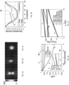
- the MCRT algorithm discussed, for example, by Ramella-Roman et al. in Opt. Express, 13, 10392-10405, 2005 ) was employed to simulate a DRP pattern of the polarized light back-scattered by a medium sample with the use of an LSR experimental set up ( Fig. 1 ). The same set-up was later use to procure empirical results for comparison.
- the sample 150 was illuminated by electromagnetic radiation emitted from a source 110 and a high-speed camera 132 was used to capture the temporally fluctuating back-scattered speckle patterns, induced by Brownian movements of scattering particles intrinsically present in the sample 150.
- the specific embodiment 100 of the experimental set up included an illumination portion with a laser source 110 producing output light 110A that, upon passing through an optical train including a linear polarizer 114 and an optional beam expander 118, was directed to the sample 150 through an optical system 120 that contains an optional lens 122 and a beam splitter 124.
- the sample 150 may be represented, for example, by synovial fluid, vitreous humor, mucus, blood - whether whole blood or individual constituents of blood, bile, or cerebrospinal fluid, to name just a few.
- the depth-resolved mapping of the sample 150 could be realized.
- light 110A could be transmitted through an optical fiber 126 prior to traversing the polarizer 114.
- Time series of images of the sample 150 in light 128 backscattered by the sample 150 was acquired through a polarizer (analyzer) 130 in a detection portion of the system 100 with a high-speed CMOS camera 132 (such as Basler Ace 2000-340km, Germany) through a lens with adjustable focal length (such as, for example, a focusing lens system MLH-10x by Computar, Commack, NY).
- CMOS camera 132 such as Basler Ace 2000-340km, Germany
- a lens with adjustable focal length such as, for example, a focusing lens system MLH-10x by Computar, Commack, NY.
- the mutual orientation of the polarizer 114 and the analyzer 130 may generally differ depending on the scope of the optical data acquisition, and is not limited to a particular orientation.
- the corresponding transmission axes may be collinear, perpendicular to one another to form a so-called cross-orientation, or form a different angle.
- the angle at which the sample 150 is illuminated may differ from the angle at which the detection portion of the system collects light scattered by the sample 150.
- the use of the CMOS camera 132 to acquire laser speckle patterns from the sample 150 enhanced the statistical accuracy in measuring g 2 (t) by simultaneous ensemble averaging of multiple speckle spots, which significantly reduces data acquisition time.
- the acquired imaging data were stored and processed with the use of a pre-programmed electronic circuitry that included a programmable processor such as a computer processor 136 and tangible non-transitory computer-readable storage medium (not shown), and further optionally displayed for visualization in a required format on a display (not shown).
- a programmable processor such as a computer processor 136 and tangible non-transitory computer-readable storage medium (not shown)
- the acquisition of the imaging data representing the sample 150 in light 128 was conducted at a predetermined rate (measured in frames-per-second, fps) to ensure that fast sample dynamics is appropriately detected, during the acquisition time periods (of portions of a second to several seconds).
- the acquired sequences of speckle patterns could be optionally additionally processed to obtain temporally-averaged irradiance (of a DRP) for a sample's region of interest (ROI) of a chosen size (for example, for about 296-by-296 pixels, which, considering the described optics, corresponds to the field -of-view (FOV) of about 1 mm 2 ).
- ROI region of interest
- FOV field -of-view
- an embodiment related to that of Fig. 1 can be adapted to operate in transmission (or forward scattering regime), with various states of polarizers 114, 1130 defining different states of polarization of light transmitted through the polarizers, and at different wavelengths.
- the set-up may incorporate at least one of a single detector, an array of photodetectors, and pinhole.
- the system when the sample 150 under test includes blood and/or its individual constituents, the system may be structured as an optical blood-coagulation sensor disclosed in PCT/US2013/076470 (and, in particular, in reference to Figs. 10A and 10B of that patent application), and include a sample-carrying cartridge and an optical system containing an array of optical apertures between the sample and the optical detector of the data acquisition portion of the LSR system, which array is used to improve spatial contrast and reduces blurring in the optical data acquired by the detector.
- PCT/US2013/076470 published as WO 2014/100378 , is incorporated herein by reference.
- the algorithm was optionally structured to take into account the experimental configuration of the LSR setup 100 - such as linearly polarized focused illumination (690 nm), finite slab geometry of the sample 150, and back-reflected (180°) collection of light through the linear polarizer 130.
- linearly polarized focused illumination (690 nm)
- finite slab geometry of the sample 150 finite slab geometry of the sample 150
- back-reflected (180°) collection of light through the linear polarizer 130 was established.
- the Mie theory was used to calculate ⁇ a , ⁇ s ', and the elements of Mueller matrix, S11, S12, S33, and S34, as discussed below.
- Data input to the MCRT algorithm included known optical properties.
- the beam of light, incident onto the sample 150, was represented during the calculation by 10 6 photons.
- the Stokes vector, S was updated via multiplication with the Mueller matrix.
- the irradiance of light retaining the initial polarization state was calculated using the scalar multiplication of S with S0.
- the spatial DRP pattern was calculated by spatial binning, which terms refers to creating a 2D-spatial histogram of photon flux components that exhibit a desirable polarization state.
- the microspheres had radii ranging from about 0.1 microns to about 3 microns (produced by PolySciences, Inc., Warrington, PA).
- One hundred ⁇ l of each sample was loaded in an imaging chamber (Grace Bio-Labs Inc., OR) for LSR evaluation.
- an imaging chamber Grace Bio-Labs Inc., OR
- light from a polarized laser (690 nm) was collimated and focused via a lens to a 50 ⁇ m spot on the sample.
- the back-scattered speckle patterns were acquired for 0.67 seconds at 753 fps.
- the DRP patterns were obtained with the use of the LSR modality, and, in one case, by temporally averaging the laser-speckle frames.
- the refractive index parameters for media components used for simulations are listed at the left-hand side of the DPR distributions, while the scale bars represent the normalized irradiance values.
- the ratio Î procured from the series of empirically acquired DRPs from a sample characterized by the n i value, is used as a quantitative representation of a DRP shape that evolves, for that n i value, with changes of the light-scattering particle size a.
- other metrics could be used such as those including ratios of intensities at different azimuthal angles or even simply the maximum values of intensities at specifically chosen angles.
- Fig. 2F illustrates the changes in Î vs. a derived from Figs. 2A through 2D (i.e., from the results of both theoretical simulations and the experimentally verified results).
- the value of ratio Î grows monotonically as a increases from 100 nm to 2 ⁇ m, and eventually reaches saturation.
- a calibration map (or reference map, which may be presented as a set of calibration curves or a calibration/reference table of data) has been formed.
- Three (3) calibration curves from such set, formed through cubic interpolation of discrete values Î in this instance for n i 1.03, 1.1, and 1.2 (curves III, II, I, respectively), are shown in dashed lines in Fig. 2F , .
- the calibration curves provide reference points and data for typical small, medium, and large n i values of specimens tested below and other common biomaterials.
- the calibration curves (procured from data representing theoretically simulated dependencies of DRPs on a and n i and representing the ratio of normalized light irradiance values taken at first and second different values of azimuthal angle) are used to derive the value of a for a given biofluidic sample characterized by a value of n i that is covered by the calibration map.
- Example 1 Determination of Viscoelastic Modulus of a Material
- the differences between the experimental plots of Fig. 3D and the MCRT-generated plots in Fig. 2E are attributed to the differences in optical properties ( n i and ⁇ s ' ) and poly-dispersity of the materials, as well as the attributes of experimental factors like camera gain and exposure time.
- the values of the ratio Î was determined from the experimentally-acquired plots of Fig. 3D , to be 0.4 (soap), 0.42 (conditioner), and 0.77 (mayonnaise).
- the g2(t) curves are determined based on the same optical irradiance distributions acquired with the optical detector, as known from Our Prior Applications. Such curves, displayed in Fig. 3E , revealed that speckle fluctuations are most rapid in soap and the slowest in conditioner.
- Radial analysis of DRP (the methodology of which was discussed by Hajjarian and Nadkarni in PloS ONE, 8, e65014, 2013 and Opt.
- Fig. 3F displays the G ⁇ ( ⁇ ), obtained from the measurements according to the principles of the present invention by using the g 2 (t)-derived MSD parameters and the a values, experimentally derived as discussed above, in Eq. (1).
- G*(co) data obtained from mechanical rheometry are also shown.
- the LSR-derived curves obtained in reliance on particle size correspond closely with the conventional mechanical-rheometry results for all samples.
- mechanical rheometer results are degraded, as increased inertia inhibits proper shearing of the specimen and the loss tangent, i.e. viscous to elastic moduli ratio, is over-estimated. This is more evident in mayonnaise sample, for which the raw loss tangent increases drastically for ⁇ > 1.
- Example 2 Determination of Viscoelastic Modulus in Curing Materials or Gels with Time-Varying, Mechanical Properties.
- PDMS1 and PDMS2 samples were prepared by mixing the base and curing agent (Sylgard ® 184, Dow Corning, Belgium) in 1: 10 ratios. Silica microspheres (PolySciences, Inc.) and Borosilicate beads (Thermo Scientific, Inc. Waltham, MA) of two distinct known sizes were added to the precursor mixtures (w/v-10%, and 4%) to induce light scattering. The samples were poured in spectroscopic cuvettes for the LSR measurements.
- Speckle movies (sets of frames with images of laser-speckles in backscatter) were acquired every 30 minutes for 24 hours at 753 fps for 5 seconds. The remainders of samples were loaded in a mechanical rheometer, and the frequency sweep procedure was conducted in tandem with the LSR measurements, every 30 minutes for 24 hours. The gels fully cured in about 48 hours at room temperature.
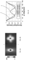
- Figs. 3A, 3B displays the DRP images of PDMS1 and PDMS2 samples, respectively.
- ⁇ s' 0.9 mm -1 and 1.4 mm -1 for PDMS1 and PDMS2 were calculated from the DRPs experimentally acquired.
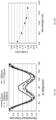
- Fig. 4C depicts the dependency of the normalized irradiance vs. the azimuthal angle ⁇ , obtained from the DRP images of Figs. 4A and 4B , as curves 1 and 2. From these curves, the Î value of 0.67 for PDMS1 and 0.87 for PDMS2 was readily derived.
- the radii of the scattering particles were determined to be a 1 ⁇ 0.25 ⁇ m and a 2 ⁇ 0.75 ⁇ m for silica and borosilicate beads, respectively (which closely agrees with manufacturer specifications ⁇ 0.25 ⁇ m and 1 ⁇ 0.25 ⁇ m).
- the time-lapsed g2(t) curves presented in Figs. 4D and 4E demonstrate the rate of speckle fluctuation during the curing of the PDMS as a function of time.
- the time-dependent MSD for the PDMS1 and PDMS2 samples was derived from the g2(t) curves and shown in insets of Figs. 4D and 4E , respectively.
- the LSR measurements agree well with mechanical rheology results and accurately follow small increments of G ⁇ , on the order of few Pa, as PDMS gel transforms from a low viscosity liquid to a primarily elastic solid with G ⁇ ⁇ 10 kPa.
- Fig. 5 provides an example of a flow-chart illustrating, schematically, an all optical method of determination of a viscoelastic parameter of a sample under test (SUT; such as a biofluidic sample, for example) carried in reliance on experimental data acquired exclusively with the use of the same, single optical system.
- SUT sample under test
- step 510 light that has interacted with a sample (including light-scattering particles in the hosting medium and characterized by n i ) and that is scattered by the sample is acquired with an optical detection unit. At least one image of the detected light distribution is formed.
- light may have high degree of optical coherence and the detected light distribution may correspond to a laser-speckle.
- the determination of light remittance (as a function of a spatial coordinate, such as a linear angle in the plane of the optical detector) is made to derive a DPR pattern based on the formed optical image(s).
- a descriptor of the experimentally-determined DPR pattern defined, in one specific example, as an experimental ratio of two normalized values of light irradiance (each corresponding to a different spatial coordinate - for example, two normalized values of light irradiance corresponding to two values of an angle), is determined.
- the determination of the averaged size of the light scatterers in the SUT is carried out.
- the determination of such averaged size at step 540 may be carried out by a) forming, at step 540A, a reference map of reference ratio values extracted from the reference DRPs.
- the reference DRPs are theoretically calculated for the variety of the speckle fields that are also determined analytically for the variety of light scatterers of different sizes and different refractive indices hosted in media having different background refractive indices; and b) determining, at step 540B, which average size of the scatterers corresponds to a point, on that reference map, that represents the descriptor of the experimentally-determined DPR pattern.
- the averaged size of light scatterers, determined from the input optical data, is further incorporated into the generalized Stokes-Einstein relation (GSER) to determine the viscoelastic modulus at step 580 with the use of the MSD data obtained, at step 570, from the same input optical data via speckle irradiance autocorrelation curves as a result of processing the optical images at step 550.
- GSER generalized Stokes-Einstein relation
- the time-dependent change of the viscoelastic modulus calculated with the use of the so-determined averaged size of the blood-sample light-scatterers, can be further utilized for determination of parameters of (blood) coagulation cascade (and, in particular, clotting time and at least one of total coagulation time, clot formation time, maximum clot firmness, maximum lysis , clot kinetics, percentage of lost clot stability at a selected point in time, rate of clotting, fibrinolysis time, clot compliance, and clot viscosity) as disclosed, for example, in U.S.
- the biofluidic sample containing whole blood or its constituents may include a stationary sample and, in particular, an in-vivo non-circulating sample.
- a method for determining the scattering particle size may be optionally employed with circulating (or moving) samples, such as flowing blood, circulating fluids and the like.
- the particle size determination is wavelength-dependent and using longer wavelengths such as, for example, 1300 nm, particles sizes of up to 10 nm and larger may be measured.
- the proposed DRP-based particle sizing methodology is primarily appealing for use during the measurements of biomaterials, where the refractive index mismatch between the light-scatterers and the hosting medium is small. For inorganic scatterers of higher refractive indices a distinct set of DRP calibration curves may be required.
- a related embodiment of the processing algorithm was employed to process a series of optical irradiance distributions detected in light scattered by the material at hand and to deduce the complex viscoelastic modulus of such material.
- temporally-resolved and temporally-averaged processing was conducted on the speckle images acquired with the LSR apparatus (similar to that of Fig. 1 ).
- the laser- speckle images (caused by coherent illumination of the sample) or diffused reflectance images (caused by speckle time averaging or sample irradiation using coherent or incoherent radiation) may be acquired at multiple wavelengths and/or multiple polarization states.
- the temporally-resolved correlation analysis of speckle images yields the speckle intensity autocorrelation function, g 2 (t).
- This processing may be performed using, for-example, electronic circuitry such as that including a programmable computer processor with the use of appropriate software (such as for instance MATLAB and C++).
- specialized hardware and processors such as for instance programmable digital correlators, may be used to calculate the acquired g 2 ( t ) curves at the hardware level.
- Box 2B of Fig. 6 describes that temporal-averaging of the speckle images yields the diffuse profile of the remitted flux. This process may be conducted by temporally averaging the same speckle frame series that are subject to temporally-resolved correlation analysis. Alternatively, capturing a single speckle image with sufficiently long exposure time may also provide the diffuse profile of the remitted flux.
- Box 3A of Fig. 6 illustrates that the diffuse remitted flux may be sectioned radially and averaged over various azimuth angles to calculate the radial profile of the flux.
- optical properties such as for example reduced scattering coefficient, ⁇ s ', and absorption coefficient, ⁇ a are calculated by fitting a proper curve obtained from the steady-state diffusion theory to the radial profile of the diffuse remittance.
- MSD is derived from speckle intensity autocorrelation curve and optical properties, with the use of a DWS formalism.
- MSD may be derived from speckle intensity autocorrelation curve and optical properties using the MCRT-derived formalism, such as the ones elaborated by Hajjarian and Nadkami in PloS ONE, 8, e65014, 2013 , which is incorporated by reference herein.
- Box 3B of Fig. 6 illustrates that the diffuse remitted flux may be sectioned azimuthally and averaged over various radial directions to calculate the azimuthal profile of the flux.
- the azimuthal profile of the flux is then depicted versus azimuth angle, ⁇ .
- ⁇ 1 and ⁇ 2 may take on different values based on the arbitrary set of illumination and detection polarization states.
- data representing the size of a scattering particle in the sample (such as for example average scattering particle size, a, and a poly-dispersity index, PDI) is calculated in reference to the corresponding calibration curves (discussed as maps in reference to Fig. 2F ) for the known values of illumination wavelength, ⁇ , and refractive index mismatch, n i .
- Box 5 of Fig. 6 illustrates that the data for MSD and a are used in the generalized and modified Stokes Einstein equation (Eq. 1) to calculate the G ⁇ ( ⁇ ).
- the sample may be illuminated by electromagnetic radiation at a single wavelength, or by using a wavelength-tunable laser source such as a tunable laser with the tunable range from about 633 nm to about 1300 nm.
- a wavelength-tunable laser source such as a tunable laser with the tunable range from about 633 nm to about 1300 nm.
- multiple different laser sources of various wavelengths or a single broadband source may be used to illuminate the sample in a predetermined order.
- optical filters may be used to preferentially select a single wavelength or multiple wavelengths for illumination.
- using multiple wavelengths for laser-speckle imaging extends the scope of DRP-based particle sizing by increasing the size range over which scattering particle size can be measured. In other words, by using multiple wavelengths, a wider range of scattering particle sizes may be retrieved from the speckle images.
- this method may enable estimating the scattering particle size distribution and its parameters in materials containing particles of various, non-uniformly distributed sizes.
- An example of such parameter may be a poly-dispersity index (PDI).
- PDI poly-dispersity index
- this method may allow determination of different particle sizes within the same sample.
- One example of this application is the determination of lipid particle size in blood or blood components including serum and plasma.
- Another example may include determination of sizes of different blood cells including red blood cells, white blood cells including platelets, lymphocytes, monocytes neutrophils and others.
- Figs. 7A, 7B, 7C, 7D, and 7E The potential of multi-wavelength illumination and detection in an embodiment of the invention is illustrated in Figs. 7A, 7B, 7C, 7D, and 7E .
- the calculation was based on assumption of the sample being illuminated with light from various laser sources at wavelengths 633nm, 800 nm, 1000 nm, 1100 nm, and 1300 nm.
- the vector of polarization of light incident on the material was assumed to be parallel to sample's surface.
- the DRP changes its shape from the clover-like shape to a bi-lobular shape.
- the second and fourth lobes forming the clover shape fade away with increase in wavelength, allowing to conclude that the shape of the DRPs depends not only on scattering particle size and refractive index mismatch but also on the illumination wavelength. This effect is attributed to the reduction of a / ⁇ , and the resulting transition between Mie and Rayleigh scattering regimes.
- Î I(90°) / I(0°) ) (or, alternatively, the ratio calculated at other angles for example at I(120°) / I(30°), I(180°) / I(45°), or another appropriate values of angles) is further procured as a quantitative representation of evolution of the DRP shape for given a and n i values, with changes of the illumination wavelength, ⁇ .
- Fig. 8B depicts a calibration map (or reference map, which may be presented as a set of calibration curves or a calibration/reference table of data) by displaying the ratio of normalized irradiances of the DRPs, Î , obtained from the data of Fig.
- the process of acquisition of optical data and the process of determination of the scattering particle size and the viscoelastic modulus value is substantially extended by operating light (that illuminating the sample and that collected by the optical detector) in one or more predetermined polarization states (such as for example, linear polarizations that are, relatively, Horizontal, Vertical, at +45°, at -45° in a chosen system of coordinates; or example right hand and left-hand circular or even elliptical polarization).
- the incident and detected polarizations states may be parallel or perpendicular to one another or, generally, these states may be in a different angular relationship.
- the polarization state of light incident onto the sample 150 may be varied manually using, for example, a simple polarizer-filter turret or wheel or alternatively in an automatic fashion with the aid of a programmable spatial light modulator (SLM), other tunable polarization modulators (for instance a photo-elastic, electro-optic modulators, or liquid-crystal-based optical modulators), or an electronic circuitry configured to govern the spatial orientation of a polarizer.
- SLM programmable spatial light modulator
- other tunable polarization modulators for instance a photo-elastic, electro-optic modulators, or liquid-crystal-based optical modulators
- an electronic circuitry configured to govern the spatial orientation of a polarizer.
- the remitted speckle images may be collected at different polarizations states either manually or automatically, using for example either polarizer wheel or other polarization dependent detectors and detection methods.
- the detected DRP patterns are substantially identical to the ones collected with the use of two linear polarizers as polarizers 114, 130), except for an arbitrary rotation angle which may also be used to detect DRP and measure particles sizes accordingly.
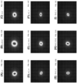
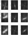
- FIG. 10A through 10I The examples of DRP patterns for multiple transmission/detection polarization state pairs are shown in Figs. 10A through 10I , 11A through 11I , and 12A through 12I .
- Figs. 10A, 10B, 10C, 10D, 10E, 10F, 10G, 10H, and 10I depict experimentally determined DRPs for Half & Half milk product with polarization states defined by polarizers 114, 130 as Horizontal-Horizontal (H-H), Fig. 10A ; Horizontal-Right Hand Circular (H-RHC), Fig. 10B ; Horizontal-Vertical (H-V) (Perpendicular to one another), Fig.
- FIG. 10C Left Hand Circular-Horizontal (LHC-H), Fig. 10D ; Left Hand Circular-Right Hand Circular (LHC-RHC) (Perpendicular states of polarization), Fig. 10E ; Left Hand Circular-vertical (LHC-V), Fig. 10F ; Right Hand Circular-Horizontal (RHC-H), Fig. 10G ; Right Hand Circular-Right Hand Circular (RHC-RHC) (co-polarized measurement), Fig. 10H ; Right Hand Circular-Vertical (RHC-V), Fig. 10I .
- Figs. 10C and 10E also illustrate that when the state of polarization of the illuminating and detected light are perpendicular to one another (cross-polarized), the DRP patterns are often clover-like and identical to one another except for a known constant rotation angle.
- the remitted DRP is likely a weighted superposition of the co-polarized and cross-polarized scenarios.
- Figs. 11 A, 11B, 11C, 11D, 11E, 11F, 11G, 11H, and 11I depict experimentally determined DRPs for Intralipid for polarization states of the polarizer 114 and the analyzer 130 identified as H-H, H-RHC, H-V , LHC-H, LHC-RHC, LHC-V, RHC-H, RHC-RHC, and RHC-V, respectively. It can be recognized from Figs. 11A and 11H that as long as the illuminating and detected light beams are co-polarized, the DRP patterns look identical except for a constant predictable rotation angle and perhaps a scaling factor. From Figs.
- Figs. 12A, 12B, 12C, 12D, 12E, 12F, 12G, 12H, and 12I depict experimentally determined DRPs for Blood with for polarization states of the polarizer 114 ad the analyzer 130 defined as H-H, H-RHC, H-V (Perpendicular to one another), LHC-H, LHC-RHC (Perpendicular to one another), LHC-V, RHC-H, RHC-RHC (Parallel to one another), and RHC-V, respectively. From Figs. 12A and 12H one can conclude that as long as the illumination and detection light beams are co-polarized, the DRP patterns look identical except for a constant predictable rotation angle and perhaps a scaling factor. From Figs.
- the DRP patterns are always clover-like and identical to one another except for a known constant rotation angle.
- polarization states of the illuminating light and the detected light are relate to each other in a different fashion (for example, the angle formed by the vectors of corresponding polarizations are neither zero nor 90 degrees), the remitted DRP is likely represented by a weighted superposition of the co-polarized and cross-polarized scenarios.
- Dispersity (or a degree of dispersity) is referred to, herein as a measure of the heterogeneity of scattering particles size in the specimen.
- Poly-dispersity and the wide particle size distribution in biological materials potentially influence the detected DRP patterns and the calibration curves.
- the methodology employed so far addresses the use of mono-disperse standard particles of identical size, a, and refractive index mismatch, n i , and investigates the influence of both a and n i and wavelength on the reflected DRP patterns and derive the calibration curves (see sets of Figs. 2 , 8 , and 9 ).
- a related embodiment of the invention turns on addressing the effect of poly-dispersity of materials on light scattering in a similar fashion.
- the detected DRP may be represented by a superposition of DRP patterns formed by subsets of scattering particles with identical sizes (for example, as a weighted sum of DRPs based on the number density and scattering cross-section of light-scattering particles).
- the total Î (such as I(90°) / I(0°) ) represents the average of Î calculated form overlaid DRPs. Since averaging is a linear operation, the calibration curves (maps) of Figs 2 , 8 , and 9 are applicable in the case of poly-disperse materials and the particle size estimated using these maps is the averaged scattering particle size.
- n i 1.03 and it was assumed that the samples were illuminated with laser light at 633 nm.
- the vector of polarization of light incident on the material is parallel to samples' surfaces, for all three samples.
- the PDIs for these samples were chosen to be different: 0 in case of Fig. 13A ; 0.1 in case of Fig. 13B ; and 0.5 in case of Fig. 13C .
- the results indicate that increasing the PDI increases the width of a love of the DRP pattern is increased with the increase of the PDI.
- Figs. 14A, 14B, 14C, 14D, 14E, 14F, 14G, 14H, 14I, 14J, 14K, 14L, 14M illustrate DRPs (for Intra-lipid, Half & Half, Butter, Synovial Fluid, Vitreous Humorous, Bile, Blood, Plasma, Cartilage, Calcific Plaque, Fibrous Plaque, Lipid-rich Plaque, respectively) that were experimentally determined with the use of the polarizer 114 and the analyzer 130 the transmission axes of which were parallel to one another.
- Fig. 15A provides a diagram illustrating the scattering of polarized light by a particle.
- the polarization states of the incident and the scattered electric fields are often described by the Stokes vector, [I Q U V].
- I S Q S U S V S 1 k 2 R 2 M
- I i Q i U i V i 1 k 2 R 2 S 11 S 12 0 0 S 12 S 22 0 0 0 0 S 33 S 34 0 0 ⁇ S 34 S 33 I i Q i U i V i
- M is the Muller matrix.
- the Stokes formulation is enabling to superimpose the Stokes parameters of the light scattered by a collection of randomly separated particles.
- the polarized MCRT algorithm of Ramella-Roman et al. was used to simulate the polarized diffuse remittance flux profile.
- Fig. 15 B presents a diagram of the ray tracing process.
- the polarized MCRT is similar to the conventional MCRT in that it tracks the path of a large number of photons from the illumination source to the detection plane to get the statistically accurate estimate of the received photon flux. Accordingly, the trajectory of a photon is simulated as a random walk in the 3-dimensional space. Upon each photon-particle collision, the traveling direction of the photon is altered.
- the azimuth and polar angle of scattering are randomly generated using marginal probability function distributions of the two angles by exploiting for example a uniform random number generated and a second random number generator based on the scattering phase function.
- the polar and azimuth angle of scattering are randomly generated using a joint probability distribution function by exploiting for example the "rejection method".
- the rejection method is implemented, for example, with the use of a software random number generator, by simultaneously assigning random numbers to the polar and azimuth angles of scattering, based on the joint probability distribution function.
- the distance between successive scattering and absorption events are assigned based on the scattering and absorption coefficients ( ⁇ s and ⁇ a ), using additional random number generators.
- Fig. 15 B An embodiment of the polarized MCRT algorithm according to the invention ( FIG. 15 B) was employed to simulate the polarized diffuse remittance patterns and to derive the Î versus a calibration curves for various refractive index pairs and illumination wavelengths.
- the Polarized MCRT model incorporated all experimental LSR parameters, and a focused Gaussian beam was assumed to illuminate the sample placed in a spectroscopic cuvette / imaging chamber (10 mm light path, 1.5 ml volume). A total of one million photons were tracked from the source 110 to the optical detector 132. Various illumination and detection wavelengths and polarization states were considered.
- the embodiment of the polarized MCRT algorithm incorporated attributes of the polarization state by tracking the Stokes' vector, [I Q U V], with respect to the corresponding reference frame.
- Meridian plane equations were used to modify the Stokes' vector upon scattering and transport within the medium. In other words, upon each photon-particle interaction or scattering, the Stokes vector was updated via multiplication to the Mueller matrix as shown above. (Alternatively, "Euler” or “Quaternion" MCRT formalisms may be used to simulate the remitted polarized flux patterns).
- a final rotation was applied (with the detection polarizer) to redefine the Stokes' vector in the receiver coordinates system and the rapidly evolving speckle pattern of the polarized component, exhibiting assorted angles, such as for example parallel, perpendicular, 45°, and/or rotating with respect to the incident polarization state were calculated.
- the elements of the Mueller matrix depend on scattering particle size, refractive index mismatch, and illumination wavelength.
- the polarized MCRT algorithm was employed to address the situation of poly-dispersity, as explained above.
- the results of Fig. 13 are obtained using this modified polarized MCRT code. More specifically, the use of the Stokes formulation enables one to superimpose the Stokes parameters of the light scattered by a collection of randomly separated particles.
- the Mie scattering solution corresponding to poly-dispersed materials was obtained by averaging the S 1 ( ⁇ ) and S 2 ( ⁇ ) over the scattering particle size distribution. Subsequently, Mueller matrix elements were derived from the averaged S 1 ( ⁇ ) and S 2 ( ⁇ ) .
- a method for determining viscoelastic modulus of a sample from laser speckle patterns which includes a step of detecting (with an optical detector of the LSR imaging system) light that has interacted with the sample to form an image of laser speckle associated with scattering of the light at light-scattering particles of the sample (which light scattering particles are particles inherent to the sample).
- the sample is free of external influence such as pressure or external force applied for particle activation and, in addition or alternatively, the sample may be moving or stationary (and, in particular, it may contain an in-vivo non-circulating biofluid or biofluid component).
- the step of detecting may include detecting light in a sequence of images of the laser speckle to determine changes of the viscoelastic modulus with time.
- the method further includes a process of forming a spatial pattern of the DRP as a function of angle (for example, an azimuth angle in a plane of the optical detector) representing the laser speckle image (optionally, as a result of time-averaging approach), and determining, from the formed DRP pattern, an experimental value of a ratio of a first normalized irradiance to a second normalized irradiance.
- the first normalized irradiance may be a value of irradiance of light, from the DRP pattern, that corresponds to a first value of the angle, while the second normalized irradiance being a value of irradiance of light, from said DRP pattern, corresponding to a second value of the angle.
- the first and second values of the angle may be chosen such as to maximize a change of the resulting experimental ratio per unit of a change in size of the light scattering particles, for example).
- the method may further include defining an average size of the light-scattering particles of the sample based on locating a point that corresponds to the experimental value of the ratio, on a reference, pre-determined map representing dependencies of values of said ratio on average size values for different values of index mismatch parameter.
- the index mismatch parameter is defined to differentiate the index of the material of light-scattering particles from the index of the material of the sample medium in which such particles are contained.
- the index mismatch parameter may be defined by a ratio of the corresponding indices of refraction, but generally a differently defined index mismatch parameter can be used (such as a refractive index difference, for example).
- the calculation of the viscoelastic modulus of the sample now takes into account and incorporates the so-determined average size of light-scattering particles, and may additionally include the use of autocorrelation curve(s) determined from the LSR image(s) of the laser speckle pattern and the mean-square displacement of the light-scattering particles calculated from these autocorrelation curves.
- autocorrelation curve(s) determined from the LSR image(s) of the laser speckle pattern
- mean-square displacement of the light-scattering particles calculated from these autocorrelation curves calculated from these autocorrelation curves.
- the method may additionally include a step of deriving from the optical data representing LSR image(s), and with a programmed processor operably cooperated with the LSR imaging system, parameters of a blood coagulation cascade including clotting time (CT) and at least one of total coagulation time, clot formation time (CFT), maximum clot firmness (MCF), maximum lysis (ML), percentage of lost clot stability at a selected point in time, rate of clotting, fibrinolysis time, clot compliance, and clot viscosity.
- CT clotting time
- CFT maximum clot firmness
- MMF maximum clot firmness
- ML maximum lysis
- the measurement of the DRP from the total flux of light reaching the optical detector may amount to either measuring a summation of speckle patterns varying in time or measurements of diffused light that is substantially incoherent.
- a system for use in determining a viscoelastic modulus of a sample includes an optical illumination portion configured to deliver light to the sample; a data acquisition portion with an optical detector unit that is configured to receive light (delivered to the sample by the optical illumination portion and that has interacted with the sample) to acquire optical data representing scattering of said light by multiple light-scattering events within the sample; and a processor operably cooperated with said optical data acquisition portion.
- the processor is specifically programmed to determine a size of the light-scattering particles causing the multiple light-scattering events based on a diffuse remittance profile (DRP) derived from the optical data; and to calculate a mean square displacement (MSD) value for said light-scattering particles and a mechanical property of the sample from the optical data.
- the optical illumination portion includes a first optical polarizer unit; the optical data acquisition portion includes a second optical polarizer unit, and t least one of the first and second optical polarizer units define respectively corresponding first and second polarization states of light transmitted therethrough in a variable fashion.
- the first and second optical polarizer units disposed in optical communication such that light that has passed through the first unit interacts with the sample and then passes through the second unit towards the optical detector unit.
- at least one of the first and second optical polarizer units may be configured to vary a polarization state of light propagating therethrough in response to an input applied to the at least one of the first and second optical polarizer units (for example, at least one of the first and second optical polarizer units may include at least one of an electro-optical material, a photo-elastic material, and a liquid-crystal material the properties of which are modulated, in real time, by the user).
- the first and second states of polarization of light transmitted through the first and second polarizer units may be equal.
- the first and second states of polarization include linear polarizations may have corresponding vectors that are collinear, as viewed along a direction of propagation of light through the first and second optical polarizer units. Alternatively, these vectors may be transverse to one another.
- the system may be structured such that a first optical axis of the optical illumination portion forms a first angle with respect to a surface of the sample, and a second optical axis defined by the optical data acquisition portion forms a second angle with respect to the surface, the first and second angles being different.
- the optical illumination portion may include at least one light source configured to generate light at at least one wavelength: it may include a wavelength-tunable laser source; a source of incoherent light, a broadband source of light.
- references throughout this specification to "one embodiment,” “an embodiment,” “a related embodiment,” or similar language mean that a particular feature, structure, or characteristic described in connection with the referred to “embodiment” is included in at least one embodiment of the present invention.
- appearances of the phrases “in one embodiment,” “in an embodiment,” and similar language throughout this specification may, but do not necessarily, all refer to the same embodiment. It is to be understood that no portion of disclosure, taken on its own and in possible connection with a figure, is intended to provide a complete description of all features of the invention.
- the schematic flow chart diagram is included, it is generally set forth as a logical flow-chart diagram. As such, the depicted order and labeled steps of the logical flow are indicative of one embodiment of the presented method. Other steps and methods may be conceived that are equivalent in function, logic, or effect to one or more steps, or portions thereof, of the illustrated method. Additionally, the format and symbols employed are provided to explain the logical steps of the method and are understood not to limit the scope of the method. Although various arrow types and line types may be employed in the flow-chart diagrams, they are understood not to limit the scope of the corresponding method. Indeed, some arrows or other connectors may be used to indicate only the logical flow of the method.
- an arrow may indicate a waiting or monitoring period of unspecified duration between enumerated steps of the depicted method.
- the order in which processing steps or particular methods occur may or may not strictly adhere to the order of the corresponding steps shown.
- Data acquisition and data processing steps facilitating the operability of an embodiment of the invention may be performed by a processor controlled by instructions stored in a memory.
- the memory may be random access memory (RAM), read-only memory (ROM), flash memory or any other non-transitory tangible storage memory, or combination thereof, suitable for storing control software or other instructions and data.
- RAM random access memory
- ROM read-only memory
- flash memory any other non-transitory tangible storage memory, or combination thereof, suitable for storing control software or other instructions and data.
- instructions or programs defining the functions of the present invention may be delivered to a processor in many forms, including, but not limited to, information permanently stored on non-writable storage media (e.g. read-only memory devices within a computer, such as ROM, or devices readable by a computer I/O attachment, such as CD-ROM or DVD disks), information alterably stored on writable storage media (e.g.
- the invention may be embodied in software, the functions necessary to implement the invention may optionally or alternatively be embodied in part or in whole using firmware and/or hardware components, such as combinatorial logic, Application Specific Integrated Circuits (ASICs), Field-Programmable Gate Arrays (FPGAs) or other hardware or some combination of hardware, software and/or firmware components.
- ASICs Application Specific Integrated Circuits
- FPGAs Field-Programmable Gate Arrays
- the particle size can be determined with the use of diffused light as well; light irradiating the sample under test may be generated by a laser source (at a single wavelength or at multiple wavelengths), by a broadband source, or a source of incoherent electromagnetic radiation.
- a laser source at a single wavelength or at multiple wavelengths
- a broadband source or a source of incoherent electromagnetic radiation.
- a shape metric of said pattern may be determined with a programmable processor.
- Such metric may include at least one of a shape of a pattern lobe, a pattern lobe width, an angle between lobes of the pattern, a number of pattern lobes, and a separation of a lobe peak from a center of said pattern.
Landscapes
- Health & Medical Sciences (AREA)
- Life Sciences & Earth Sciences (AREA)
- Chemical & Material Sciences (AREA)
- Physics & Mathematics (AREA)
- General Health & Medical Sciences (AREA)
- Immunology (AREA)
- Pathology (AREA)
- General Physics & Mathematics (AREA)
- Biochemistry (AREA)
- Analytical Chemistry (AREA)
- Engineering & Computer Science (AREA)
- Biomedical Technology (AREA)
- Hematology (AREA)
- Food Science & Technology (AREA)
- Medicinal Chemistry (AREA)
- Urology & Nephrology (AREA)
- Molecular Biology (AREA)
- Ecology (AREA)
- Biophysics (AREA)
- Dispersion Chemistry (AREA)
- Investigating Or Analysing Materials By Optical Means (AREA)
- Length Measuring Devices By Optical Means (AREA)
Applications Claiming Priority (3)
| Application Number | Priority Date | Filing Date | Title |
|---|---|---|---|
| US201461934433P | 2014-01-31 | 2014-01-31 | |
| PCT/US2015/014066 WO2015160418A2 (en) | 2014-01-31 | 2015-02-02 | System and methods for estimation of mechanical properties and size of light-scattering particles in materials |
| EP15779994.1A EP3100043B1 (de) | 2014-01-31 | 2015-02-02 | System und verfahren zur schätzung der mechanischen eigenschaften und der grösse von lichtstreuenden partikeln in materialien |
Related Parent Applications (2)
| Application Number | Title | Priority Date | Filing Date |
|---|---|---|---|
| EP15779994.1A Division-Into EP3100043B1 (de) | 2014-01-31 | 2015-02-02 | System und verfahren zur schätzung der mechanischen eigenschaften und der grösse von lichtstreuenden partikeln in materialien |
| EP15779994.1A Division EP3100043B1 (de) | 2014-01-31 | 2015-02-02 | System und verfahren zur schätzung der mechanischen eigenschaften und der grösse von lichtstreuenden partikeln in materialien |
Publications (3)
| Publication Number | Publication Date |
|---|---|
| EP4235151A2 true EP4235151A2 (de) | 2023-08-30 |
| EP4235151A3 EP4235151A3 (de) | 2023-10-18 |
| EP4235151B1 EP4235151B1 (de) | 2025-08-27 |
Family
ID=54324692
Family Applications (2)
| Application Number | Title | Priority Date | Filing Date |
|---|---|---|---|
| EP23176489.5A Active EP4235151B1 (de) | 2014-01-31 | 2015-02-02 | System und verfahren zur schätzung der mechanischen eigenschaften und der grösse von lichtstreuenden partikeln in materialien |
| EP15779994.1A Active EP3100043B1 (de) | 2014-01-31 | 2015-02-02 | System und verfahren zur schätzung der mechanischen eigenschaften und der grösse von lichtstreuenden partikeln in materialien |
Family Applications After (1)
| Application Number | Title | Priority Date | Filing Date |
|---|---|---|---|
| EP15779994.1A Active EP3100043B1 (de) | 2014-01-31 | 2015-02-02 | System und verfahren zur schätzung der mechanischen eigenschaften und der grösse von lichtstreuenden partikeln in materialien |
Country Status (3)
| Country | Link |
|---|---|
| US (1) | US10191031B2 (de) |
| EP (2) | EP4235151B1 (de) |
| WO (1) | WO2015160418A2 (de) |
Families Citing this family (24)
| Publication number | Priority date | Publication date | Assignee | Title |
|---|---|---|---|---|
| US10359361B2 (en) | 2011-02-18 | 2019-07-23 | The General Hospital Corporation | Laser speckle micro-rheology in characterization of biomechanical properties of tissues |
| US10215642B2 (en) * | 2012-05-17 | 2019-02-26 | The University Of Akron | System and method for polarimetric wavelet fractal detection and imaging |
| WO2014043609A1 (en) * | 2012-09-17 | 2014-03-20 | The General Hospital Corporation | Compensation for causes of temporal fluctuations of backscattered speckle patterns in laser speckle rheology of biological fluids |
| WO2015184433A1 (en) | 2014-05-30 | 2015-12-03 | The General Hospital Corporation | Optical thromboelastography systems and methods |
| GB2537550A (en) * | 2015-07-13 | 2016-10-19 | Malvern Instr Ltd | Dynamic light scattering based optical microrheology in non-aqueous solutions |
| US11150173B2 (en) | 2016-02-12 | 2021-10-19 | The General Hospital Corporation | Laser speckle micro-rheology in characterization of biomechanical properties of tissues |
| US9851291B2 (en) * | 2016-05-02 | 2017-12-26 | Hamilton Associates, Inc. | Realtime optical method and system for detecting and classifying biological and non-biological particles |
| DE102016212164B3 (de) * | 2016-07-04 | 2017-09-21 | Fraunhofer-Gesellschaft zur Förderung der angewandten Forschung e.V. | Verfahren zur Bestimmung der mittleren Partikelgröße von Partikeln, die in einem flüssigen und fließenden Medium suspendiert sind, über dynamische Lichtstreuung und Vorrichtung hierzu |
| CN107328690B (zh) * | 2017-07-28 | 2019-06-11 | 西安交通大学 | 一种适用于测量流体近临界区域粘度的装置及方法 |
| CN107328694A (zh) * | 2017-08-03 | 2017-11-07 | 京东方科技集团股份有限公司 | 一种微粒检测装置及其检测方法 |
| CN109613039B (zh) * | 2018-10-26 | 2021-03-23 | 浙江工业大学 | 一种表征铌酸锂晶体微观结构变化的方法 |
| SE543406C2 (en) | 2019-05-15 | 2021-01-05 | Nanosized Sweden Ab | Water impurity measurements with dynamic light scattering |
| CN110907316A (zh) * | 2019-12-16 | 2020-03-24 | 中国科学院大气物理研究所 | 一种用于单颗粒物前后向散射及退偏比测量的光路系统 |
| WO2021155361A1 (en) * | 2020-01-31 | 2021-08-05 | The General Hospital Corporation | Methods and systems for non-destructive estimation of scattering particle size |
| ES3020087T3 (en) | 2020-09-21 | 2025-05-21 | Instr Laboratory Co | Detecting and monitoring oral anticoagulants or intravenous direct thrombin inhibitors in a blood sample |
| CN112504922B (zh) * | 2020-10-20 | 2022-09-02 | 华南师范大学 | 一种大气颗粒物粒径分布的在线测量系统及方法 |
| CN112748042A (zh) * | 2020-12-28 | 2021-05-04 | 华中科技大学 | 一种表征软物质粘弹性的光学微流变的装置及方法 |
| CN113092369A (zh) * | 2021-03-23 | 2021-07-09 | 华中科技大学 | 一种用于监测血液凝固动态过程的光学装置及方法 |
| CN113434090B (zh) * | 2021-06-30 | 2023-03-28 | 同济大学 | 一种用于高速视频测量的海量数据异步存储方法 |
| CN116067877A (zh) * | 2021-11-01 | 2023-05-05 | 中国石油化工股份有限公司 | 用于光散射仪的样品台及光散射仪 |
| US20250189424A1 (en) * | 2022-03-11 | 2025-06-12 | Massachusetts Institute Of Technology | System and method for real-time determination of particle size distributions in dry powders |
| WO2024159227A2 (en) * | 2023-01-27 | 2024-08-02 | The General Hospital Corporation | Systems and methods for measuring particle size in tissue and turbid media |
| WO2025178385A1 (ko) * | 2024-02-21 | 2025-08-28 | 주식회사 더웨이브톡 | 광학 측정 장치 |
| CN119354742B (zh) * | 2024-10-11 | 2025-09-09 | 武汉大学 | 基于光学测量技术的颗粒材料细观力学试验平台及方法 |
Citations (3)
| Publication number | Priority date | Publication date | Assignee | Title |
|---|---|---|---|---|
| WO2014043609A1 (en) | 2012-09-17 | 2014-03-20 | The General Hospital Corporation | Compensation for causes of temporal fluctuations of backscattered speckle patterns in laser speckle rheology of biological fluids |
| WO2014100378A1 (en) | 2012-12-19 | 2014-06-26 | The General Hospital Corporation | Optical blood-coagulation sensor |
| US8772039B2 (en) | 2011-05-26 | 2014-07-08 | The General Hospital Corporation | Optical thromboelastography system and method for evaluation of blood coagulation metrics |
Family Cites Families (10)
| Publication number | Priority date | Publication date | Assignee | Title |
|---|---|---|---|---|
| US3180210A (en) | 1961-07-18 | 1965-04-27 | John E Tyler | Instrument for measuring volume absorption coefficients of horizontally stratified water |
| US4134679A (en) * | 1976-11-05 | 1979-01-16 | Leeds & Northrup Company | Determining the volume and the volume distribution of suspended small particles |
| US6397099B1 (en) * | 1992-05-18 | 2002-05-28 | Non-Invasive Technology, Inc. | Non-invasive imaging of biological tissue |
| US5818583A (en) * | 1996-11-08 | 1998-10-06 | Purdue Research Foundation | Particle analysis system and method |
| US6958816B1 (en) | 2001-10-05 | 2005-10-25 | Research Foundation Of The University Of Central Florida | Microrheology methods and systems using low-coherence dynamic light scattering |
| US7202950B2 (en) * | 2003-07-08 | 2007-04-10 | Marine Biological Laboratory | Retardance measurement system and method |
| US8101424B2 (en) * | 2005-06-15 | 2012-01-24 | University Of Maryland, Baltimore County | Bioassays using plasmonic scattering from noble metal nanostructures |
| US20080220512A1 (en) | 2007-03-09 | 2008-09-11 | Nellcor Puritan Bennett Llc | Tunable laser-based spectroscopy system for non-invasively measuring body water content |
| WO2010105197A2 (en) | 2009-03-12 | 2010-09-16 | The General Hospital Corporation | Non-contact optical system, computer-accessible medium and method for measuring at least one mechanical property of tissue using coherent speckle techniques(s) |
| FR2945629B1 (fr) | 2009-05-15 | 2011-06-10 | Formulaction | Procede de caracterisation rheologique d'un milieu complexe |
-
2015
- 2015-02-02 EP EP23176489.5A patent/EP4235151B1/de active Active
- 2015-02-02 WO PCT/US2015/014066 patent/WO2015160418A2/en not_active Ceased
- 2015-02-02 EP EP15779994.1A patent/EP3100043B1/de active Active
- 2015-02-02 US US15/114,868 patent/US10191031B2/en active Active
Patent Citations (3)
| Publication number | Priority date | Publication date | Assignee | Title |
|---|---|---|---|---|
| US8772039B2 (en) | 2011-05-26 | 2014-07-08 | The General Hospital Corporation | Optical thromboelastography system and method for evaluation of blood coagulation metrics |
| WO2014043609A1 (en) | 2012-09-17 | 2014-03-20 | The General Hospital Corporation | Compensation for causes of temporal fluctuations of backscattered speckle patterns in laser speckle rheology of biological fluids |
| WO2014100378A1 (en) | 2012-12-19 | 2014-06-26 | The General Hospital Corporation | Optical blood-coagulation sensor |
Non-Patent Citations (5)
| Title |
|---|
| HAJJARIANNADKARNI, PLOS ONE, vol. 8, 2013, pages e65014 |
| HIELSCHER ET AL., APPL. OPT., vol. 36, 1997, pages 125 - 135 |
| J. RAMELLA-ROMAN ET AL.: "Three Monte Carlo programs of polarized light transport into scattering media: part I", OPT. EXPRESS, vol. 13, 2005, pages 10392 - 10405 |
| WAX ET AL., J. OPT. SOC. AM. A, vol. 19, 2002, pages 737 - 744 |
| Z. HAJJARIAN ET AL., OPT. EXPRESS, vol. 22, 2014, pages 6349 - 6361 |
Also Published As
| Publication number | Publication date |
|---|---|
| EP3100043A4 (de) | 2017-09-13 |
| US10191031B2 (en) | 2019-01-29 |
| WO2015160418A3 (en) | 2015-12-10 |
| EP3100043A2 (de) | 2016-12-07 |
| EP3100043B1 (de) | 2024-08-28 |
| EP4235151B1 (de) | 2025-08-27 |
| US20170003271A1 (en) | 2017-01-05 |
| EP4235151A3 (de) | 2023-10-18 |
| WO2015160418A2 (en) | 2015-10-22 |
Similar Documents
| Publication | Publication Date | Title |
|---|---|---|
| EP4235151B1 (de) | System und verfahren zur schätzung der mechanischen eigenschaften und der grösse von lichtstreuenden partikeln in materialien | |
| EP2713878B1 (de) | Optisches thromboelastographiesystem und verfahren zur bewertung von blutgerinnungsmetriken | |
| US9664606B2 (en) | Compensation for causes of temporal fluctuations of backscattered speckle patterns in laser speckle rheology of biological fluids | |
| US8697449B2 (en) | Optical blood coagulation monitor and method | |
| Lemaillet et al. | Double-integrating-sphere system at the National Institute of Standards and Technology in support of measurement standards for the determination of optical properties of tissue-mimicking phantoms | |
| US12366512B2 (en) | Methods and systems for non-destructive estimation of scattering particle size | |
| Hajjarian et al. | Evaluation and correction for optical scattering variations in laser speckle rheology of biological fluids | |
| EP2960635A1 (de) | Vorrichtung zur messung von dynamischer lichtstreuung und verfahren zur messung von dynamischer lichtstreuung | |
| CN109900663A (zh) | 激光光源散斑测量方法、散斑抑制装置及其参数优化方法 | |
| JP2013502568A (ja) | 改良型単一散乱モード検出を有する、複合流体の動的光散乱型マイクロレオロジー | |
| Post et al. | Experimental validation of a recently developed model for single-fiber reflectance spectroscopy | |
| RU2669154C1 (ru) | Способ измерения параметров фазового перехода жидкость-жидкость в водных растворах амфифилов | |
| US10520431B2 (en) | Particle analyzer, particle analysis method, and particle analysis program | |
| Corral et al. | Tissue characterization with ballistic photons: counting scattering and/or absorption centres. | |
| Zhao et al. | Transmission laser speckle rheological method with measurable viscoelasticity of biological liquid inside tissue | |
| Ghassemi et al. | Towards skin polarization characterization using polarimetric technique | |
| JP2020533584A (ja) | ゲル線量計によって吸収された放射の線量を偏光した光を利用して光学的に計測する装置 | |
| Chicea et al. | Using CHODIN to simulate coherent light scattering dynamics on biological suspensions | |
| Khlynov et al. | Noninvasive polarization-based technique for hematocrit monitoring | |
| Abou Nader et al. | Scattering spot imaging for the determination of optical and dynamical properties of viscoelastic media | |
| Nakamura et al. | High-sensitivity low-coherence dynamic light scattering and particle sizing for nanoparticles (II): SM-fiber probe system applied to dense particle suspensions | |
| Roy et al. | Non-invasive tracking of polarization rotation from speckle contrast measurement | |
| Chicea | Results of sediment motion visualization by a modified LASCA technique | |
| Abubaker et al. | Backward multiscattering and transport of photons in biological tissue: experiment and simulation | |
| Zhang | Measurements of diffuse backscattering Mueller matrices of turbid media |
Legal Events
| Date | Code | Title | Description |
|---|---|---|---|
| PUAI | Public reference made under article 153(3) epc to a published international application that has entered the european phase |
Free format text: ORIGINAL CODE: 0009012 |
|
| STAA | Information on the status of an ep patent application or granted ep patent |
Free format text: STATUS: THE APPLICATION HAS BEEN PUBLISHED |
|
| AC | Divisional application: reference to earlier application |
Ref document number: 3100043 Country of ref document: EP Kind code of ref document: P |
|
| AK | Designated contracting states |
Kind code of ref document: A2 Designated state(s): AL AT BE BG CH CY CZ DE DK EE ES FI FR GB GR HR HU IE IS IT LI LT LU LV MC MK MT NL NO PL PT RO RS SE SI SK SM TR |
|
| REG | Reference to a national code |
Ref country code: DE Ref legal event code: R079 Free format text: PREVIOUS MAIN CLASS: G01N0021470000 Ipc: G01N0033000000 Ref country code: DE Ref legal event code: R079 Ref document number: 602015092281 Country of ref document: DE Free format text: PREVIOUS MAIN CLASS: G01N0021470000 Ipc: G01N0033000000 |
|
| PUAL | Search report despatched |
Free format text: ORIGINAL CODE: 0009013 |
|
| AK | Designated contracting states |
Kind code of ref document: A3 Designated state(s): AL AT BE BG CH CY CZ DE DK EE ES FI FR GB GR HR HU IE IS IT LI LT LU LV MC MK MT NL NO PL PT RO RS SE SI SK SM TR |
|
| RIC1 | Information provided on ipc code assigned before grant |
Ipc: G01N 21/00 20060101ALI20230913BHEP Ipc: G01N 21/47 20060101ALI20230913BHEP Ipc: G01N 21/51 20060101ALI20230913BHEP Ipc: G01N 33/49 20060101ALI20230913BHEP Ipc: G01N 21/21 20060101ALI20230913BHEP Ipc: G01N 11/00 20060101ALI20230913BHEP Ipc: G01N 15/02 20060101ALI20230913BHEP Ipc: G01N 33/00 20060101AFI20230913BHEP |
|
| STAA | Information on the status of an ep patent application or granted ep patent |
Free format text: STATUS: REQUEST FOR EXAMINATION WAS MADE |
|
| 17P | Request for examination filed |
Effective date: 20240417 |
|
| RBV | Designated contracting states (corrected) |
Designated state(s): AL AT BE BG CH CY CZ DE DK EE ES FI FR GB GR HR HU IE IS IT LI LT LU LV MC MK MT NL NO PL PT RO RS SE SI SK SM TR |
|
| GRAP | Despatch of communication of intention to grant a patent |
Free format text: ORIGINAL CODE: EPIDOSNIGR1 |
|
| STAA | Information on the status of an ep patent application or granted ep patent |
Free format text: STATUS: GRANT OF PATENT IS INTENDED |
|
| INTG | Intention to grant announced |
Effective date: 20250318 |
|
| GRAS | Grant fee paid |
Free format text: ORIGINAL CODE: EPIDOSNIGR3 |
|
| GRAA | (expected) grant |
Free format text: ORIGINAL CODE: 0009210 |
|
| STAA | Information on the status of an ep patent application or granted ep patent |
Free format text: STATUS: THE PATENT HAS BEEN GRANTED |
|
| AC | Divisional application: reference to earlier application |
Ref document number: 3100043 Country of ref document: EP Kind code of ref document: P |
|
| AK | Designated contracting states |
Kind code of ref document: B1 Designated state(s): AL AT BE BG CH CY CZ DE DK EE ES FI FR GB GR HR HU IE IS IT LI LT LU LV MC MK MT NL NO PL PT RO RS SE SI SK SM TR |
|
| REG | Reference to a national code |
Ref country code: CH Ref legal event code: EP |
|
| REG | Reference to a national code |
Ref country code: DE Ref legal event code: R096 Ref document number: 602015092281 Country of ref document: DE |
|
| REG | Reference to a national code |
Ref country code: IE Ref legal event code: FG4D |