EP4235051B1 - Luftleitungskomponent und luftklimaanlage mit diesem komponent - Google Patents
Luftleitungskomponent und luftklimaanlage mit diesem komponent Download PDFInfo
- Publication number
- EP4235051B1 EP4235051B1 EP21885122.8A EP21885122A EP4235051B1 EP 4235051 B1 EP4235051 B1 EP 4235051B1 EP 21885122 A EP21885122 A EP 21885122A EP 4235051 B1 EP4235051 B1 EP 4235051B1
- Authority
- EP
- European Patent Office
- Prior art keywords
- air
- air deflection
- deflector
- airflow
- bars
- Prior art date
- Legal status (The legal status is an assumption and is not a legal conclusion. Google has not performed a legal analysis and makes no representation as to the accuracy of the status listed.)
- Active
Links
Images







Classifications
-
- F—MECHANICAL ENGINEERING; LIGHTING; HEATING; WEAPONS; BLASTING
- F24—HEATING; RANGES; VENTILATING
- F24F—AIR-CONDITIONING; AIR-HUMIDIFICATION; VENTILATION; USE OF AIR CURRENTS FOR SCREENING
- F24F13/00—Details common to, or for air-conditioning, air-humidification, ventilation or use of air currents for screening
- F24F13/08—Air-flow control members, e.g. louvres, grilles, flaps or guide plates
- F24F13/10—Air-flow control members, e.g. louvres, grilles, flaps or guide plates movable, e.g. dampers
- F24F13/14—Air-flow control members, e.g. louvres, grilles, flaps or guide plates movable, e.g. dampers built up of tilting members, e.g. louvre
-
- F—MECHANICAL ENGINEERING; LIGHTING; HEATING; WEAPONS; BLASTING
- F24—HEATING; RANGES; VENTILATING
- F24F—AIR-CONDITIONING; AIR-HUMIDIFICATION; VENTILATION; USE OF AIR CURRENTS FOR SCREENING
- F24F13/00—Details common to, or for air-conditioning, air-humidification, ventilation or use of air currents for screening
- F24F13/08—Air-flow control members, e.g. louvres, grilles, flaps or guide plates
- F24F13/10—Air-flow control members, e.g. louvres, grilles, flaps or guide plates movable, e.g. dampers
- F24F13/14—Air-flow control members, e.g. louvres, grilles, flaps or guide plates movable, e.g. dampers built up of tilting members, e.g. louvre
- F24F13/1413—Air-flow control members, e.g. louvres, grilles, flaps or guide plates movable, e.g. dampers built up of tilting members, e.g. louvre using more than one tilting member, e.g. with several pivoting blades
-
- F—MECHANICAL ENGINEERING; LIGHTING; HEATING; WEAPONS; BLASTING
- F24—HEATING; RANGES; VENTILATING
- F24F—AIR-CONDITIONING; AIR-HUMIDIFICATION; VENTILATION; USE OF AIR CURRENTS FOR SCREENING
- F24F1/00—Room units for air-conditioning, e.g. separate or self-contained units or units receiving primary air from a central station
- F24F1/0007—Indoor units, e.g. fan coil units
- F24F1/0011—Indoor units, e.g. fan coil units characterised by air outlets
-
- F—MECHANICAL ENGINEERING; LIGHTING; HEATING; WEAPONS; BLASTING
- F24—HEATING; RANGES; VENTILATING
- F24F—AIR-CONDITIONING; AIR-HUMIDIFICATION; VENTILATION; USE OF AIR CURRENTS FOR SCREENING
- F24F1/00—Room units for air-conditioning, e.g. separate or self-contained units or units receiving primary air from a central station
- F24F1/0007—Indoor units, e.g. fan coil units
- F24F1/0011—Indoor units, e.g. fan coil units characterised by air outlets
- F24F1/0014—Indoor units, e.g. fan coil units characterised by air outlets having two or more outlet openings
-
- F—MECHANICAL ENGINEERING; LIGHTING; HEATING; WEAPONS; BLASTING
- F24—HEATING; RANGES; VENTILATING
- F24F—AIR-CONDITIONING; AIR-HUMIDIFICATION; VENTILATION; USE OF AIR CURRENTS FOR SCREENING
- F24F13/00—Details common to, or for air-conditioning, air-humidification, ventilation or use of air currents for screening
- F24F13/08—Air-flow control members, e.g. louvres, grilles, flaps or guide plates
- F24F13/081—Air-flow control members, e.g. louvres, grilles, flaps or guide plates for guiding air around a curve
-
- F—MECHANICAL ENGINEERING; LIGHTING; HEATING; WEAPONS; BLASTING
- F24—HEATING; RANGES; VENTILATING
- F24F—AIR-CONDITIONING; AIR-HUMIDIFICATION; VENTILATION; USE OF AIR CURRENTS FOR SCREENING
- F24F1/00—Room units for air-conditioning, e.g. separate or self-contained units or units receiving primary air from a central station
- F24F1/0007—Indoor units, e.g. fan coil units
- F24F1/0043—Indoor units, e.g. fan coil units characterised by mounting arrangements
- F24F1/0057—Indoor units, e.g. fan coil units characterised by mounting arrangements mounted in or on a wall
-
- F—MECHANICAL ENGINEERING; LIGHTING; HEATING; WEAPONS; BLASTING
- F24—HEATING; RANGES; VENTILATING
- F24F—AIR-CONDITIONING; AIR-HUMIDIFICATION; VENTILATION; USE OF AIR CURRENTS FOR SCREENING
- F24F13/00—Details common to, or for air-conditioning, air-humidification, ventilation or use of air currents for screening
- F24F13/02—Ducting arrangements
- F24F13/06—Outlets for directing or distributing air into rooms or spaces, e.g. ceiling air diffuser
Definitions
- the present disclosure relates to the field of air conditioner technologies, and more particularly, the invention relates to an air deflection component and an air conditioner having same.
- the present invention further provides a first air conditioner having the first air deflection component as described above.
- a first air deflection component includes a deflector and an air deflection bar assembly.
- the air deflection bar assembly is connected at an inner side of the deflector, and includes two air deflection bars spaced apart from each other in a width direction of the deflector, wherein.
- Each of the two air deflection bars is configured to deflect an airflow flowing from the inner side to an outer side of the deflector in a direction facing away from another one of the two air deflection bars.
- An airflow channel is formed between the two air deflection bars.
- a multi-dimensional air blowing can be realized to accelerate disturbance of air in an entire room and enhance micro-circulation of the air in the room. As a result, there is no stuffy feeling for the user in the room.
- the temperature can be rapidly adjusted to improve temperature uniformity and enhance comfort experience of a user.
- a first air conditioner includes a body, the first air deflection component as described in the above embodiments, and a drive mechanism.
- a first air passage is formed in the body.
- the body has an air inlet and a first air outlet that are in communication with the first air passage.
- the first air deflection component is disposed at the first air outlet.
- the drive mechanism is connected between the first air deflection component and the body. The drive mechanism is configured to drive the first air deflection component to be movable relative to the body.
- the multi-dimensional air blowing can be realized to accelerate the disturbance of the air in the entire room and enhance the micro-circulation of the air in the room.
- the temperature can be rapidly adjusted to improve the temperature uniformity and enhance the comfort experience of the user.
- overall performance of the first air conditioner can be improved.
- a second air deflection component for a second air conditioner.
- a second air passage is formed in the second air conditioner.
- An end of the second air passage is formed as a second air outlet.
- the second air deflection component is configured to be movable between a first position for closing the second air outlet and a second position for exposing the second air outlet.
- the second air deflection component includes a first connection plate and a second connection plate that are arranged in a thickness direction. The second air outlet is closed by the first connection plate when the second air deflection component is positioned in the first position.
- the second air deflection component is positioned in the second position, a first airflow channel is formed between the second air passage and a part of the first connection plate, and a second airflow channel is formed between the second air passage and another part of the first connection plate.
- the first airflow channel and the second airflow channel extend towards two opposite sides of the second air outlet, respectively.
- the multi-dimensional air blowing can be realized to accelerate the disturbance of the air in the entire room and enhance the micro-circulation of the air in the room. As a result, there is no stuffy feeling for the user in the room.
- the temperature can be rapidly adjusted to improve the temperature uniformity and enhance the comfort experience of the user.
- a second air conditioner includes a second air passage component and the second air deflection component for the second air conditioner as described in the above embodiments.
- a second air passage is formed by the second air passage component and has an end formed as a second air outlet.
- the second air deflection component is connected to the second air passage component, and is configured to be movable between the first position for closing the second air outlet and the second position for exposing the second air outlet.
- the multi-dimensional air blowing can be realized to accelerate the disturbance of the air in the entire room and enhance the micro-circulation of the air in the room. As a result, there is no stuffy feeling for the user in the room.
- the temperature can be rapidly adjusted to improve the temperature uniformity and enhance the comfort experience of the user.
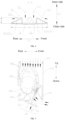
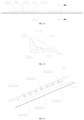
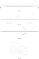
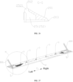
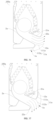
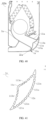
- a first air deflection component 100 and a first air conditioner 1000 having the first air deflection component 10 according to embodiments of the present invention will be described below with reference to the accompanying drawings.
- the first air deflection component 100 is not limited to being applied in the first air conditioner 1000. That is, the first air deflection component 100 may also be applied in other devices having an air blowing function, such as an air purifier. Further, it should be noted that, a type of the first air conditioner 1000 to which the first air deflection component 100 according to the embodiments of the present invention is applied is not limited.
- the first air deflection component 100 may be applied in an all-in-one air conditioner such as a mobile air conditioner, a window air conditioner.
- the first air deflection component 100 may also be applied in a split air conditioner such as an air conditioning wall-mounted indoor unit, an air conditioner cabinet unit.
- the first air deflection component 100 is applied in the first air conditioner 1000.
- the first air conditioner 1000 has a first air outlet 200 and an air inlet 300. An airflow enters the first air conditioner 1000 from the air inlet 300 and exits the first air conditioner 1000 from the first air outlet 200.
- the first air deflection component 100 is disposed at the first air outlet 200 to at least regulate an air blowing effect of the first air outlet 200.
- the first air deflection component 100 may include a deflector 1 and an air deflection bar assembly 2.
- the air deflection bar assembly 2 is connected on an inner side of the deflector 1. It should be noted that, a side of the deflector 1 close to the first air outlet 200 is the inner side of the deflector 1, and a side of the deflector 1 facing away from the first air outlet 200 is an outer side of the deflector 1.
- the air deflection bar assembly 2 is disposed on the inner side of the deflector 1 and connected to the deflector 1. That is, the air deflection bar assembly 2 is disposed on a windward side of the deflector 1 to provide air deflecting function.
- the air deflection bar assembly 2 and the deflector 1 may be separately formed and assembled (including detachably assembled, non-detachably assembled, or the like) with each other, or may be integrally formed (including integral molding, over-injection molding, or the like).
- the air deflection bar assembly 2 includes two air deflection bars 20 spaced apart from each other in a width direction F2 of the deflector 1.
- Each of the two air deflection bars 20 is configured to deflect an airflow flowing from the inner side to the outer side of the deflector 1 in a direction facing away from the other one of the two air deflection bars 20.
- the air deflection bar assembly 2 includes two air deflection bars 20, i.e., a first air deflection bar 21 and a second air deflection bar 22.
- the first air deflection bar 21 and the second air deflection bar 22 are spaced apart from each other in the width direction F2 of the deflector 1.
- the first air deflection bar 21 is configured to deflect the airflow flowing from the inner side to the outer side of the deflector 1 in the direction facing away from the second air deflection bar 21 (e.g., a direction indicated by line S1 illustrated in FIG. 4 ).
- the second air deflection bar 22 is configured to deflect the airflow flowing from the inner side to the outer side of the deflector 1 in a direction facing away from the first air deflection bar 21 (e.g., a direction indicated by line S2 illustrated in FIG. 4 ).
- the two air deflection bars 20 spaced apart in a transverse direction of the deflector 1 are disposed on the inner side of the deflector 1.
- Each of the two air deflection bars 20 can deflect air in a direction facing away the other one of the two air deflection bars 20 to achieve adjustable air blowing in at least two directions (adjustable air blowing in the direction S1 and the direction S2 illustrated in FIG. 4 ). Therefore, it is possible to allow for a rapid adjustment of a temperature of an entire room and improved uniformity of temperature diffusion. Further, the air in the room can be disturbed to a great extent to assuage stuffiness felt by the user. In addition, the air blowing can be adjusted to a great extent through a rotation at a relatively small angle, which thus can reduce energy consumption to drive movements of the first air deflection component 100 and achieve more significant adjustment to air directions and air volumes.
- the first air deflection component 100 when the first air deflection component 100 according to the embodiments of the present disclosure is applied in the air conditioner wall-mounted indoor unit, it is possible to solve problems that cold air is blown directly on the user and hot air cannot reach the user's feet directly.
- the first air conditioner 1000 is the air conditioner wall-mounted indoor unit.
- the first air outlet 200 is formed at a front side of a bottom and/or a lower part of a front side a body 700.
- the two air deflection bars 20 are spaced apart from each other in a front-rear direction.
- the first air deflection component 100 may be switched between a forward air blowing state (e.g., as illustrated in FIG.
- FIG. 5 in the forward air blowing state, the airflow flowing out of the first air outlet 200 is deflected forwards through the front air deflection bar 20, which can prevent the cold air from being blown directly on the user.
- the airflow flowing out of the first air outlet 200 is deflected rearwards through the rear air deflection bar 20, which can solve the problem that the hot air cannot reach the user's feet directly.
- each of the air deflection bars 20 may be constructed as an integral elongated bar structure extending in a length direction F1 of the deflector 1.
- Each of the air deflection bars 20 may also be formed by at least two short bar structures arranged sequentially in the length direction F1 of the deflector 1.
- a surface of each air deflection bar 20 for deflecting air i.e., an air deflecting surface
- the air deflecting surface of the air deflection bar 20 may include an inner surface of the air deflection bar 20, an outer surface of the air deflection bar 20, and the like.
- a side surface of the air deflection bar 20 facing away from the deflector 1 i.e., an inner side surface 201 of the air deflection bar 20
- the air deflecting surface of the air deflection bar 20 is the air deflecting surface of the air deflection bar 20.
- both the side surface of the air deflection bar 20 facing away from the deflector 1 i.e., the inner side surface 201 of the air deflection bar 20
- the inner surface of the air deflection bar 20 are the air deflecting surface of the air deflection bar 20.
- a plurality of ventilation holes 11 is formed at the deflector 1. It should be understood that, each of the plurality of ventilation holes 11 penetrates an inner side surface and an outer side surface of the deflector 1.
- An airflow channel 12 is formed between the two air deflection bars 20. The airflow channel 12 is in communication with the plurality of ventilation holes 11. In this way, the airflow flowing from the inner side to the outer side of the deflector 1 may partially enter the airflow channel 12, and then flow through the ventilation holes 11 on the deflector 1 towards outside of the deflector 1, flow in a direction indicated by line S3 illustrated in FIG. 4 .
- the first air deflection component 100 has two air blowing dimensions in which each of the two air deflection bars 20 can deflect the air in the direction facing away from the other one of the two air deflection bars 20. Further, the first air deflection component 100 has one air blowing dimension in which the air is blown through the airflow channel 12 and the ventilation holes 11. Thus, the first air deflection component 100 totally has at least three air blowing dimensions, i.e., three air blowing directions S1, S2, and S3 as illustrated in FIG. 4 .
- each of the two air deflection bars 20 to deflect the air in the direction facing away from the other one of the two air deflection bars 20
- the temperature can be rapidly adjusted to improve the temperature uniformity and enhance comfort experience of the user.
- the first air deflection component 100 when the first air deflection component 100 according to the embodiments of the present disclosure is applied in the air conditioner wall-mounted indoor unit, it is possible to solve the problems that the cold air is blown directly on the user and the hot air cannot reach the user's feet. Meanwhile, the disturbance of the air in the entire room can be accelerated through the air-blowing from the airflow channel 12 and the ventilation holes 11 to enhance the micro-circulation of the air in the room. As a result, there is no stuffy feeling for the user in the room, which can solve a problem of a lack of comfort due to a single-dimensional air blowing. Therefore, the multi-dimensional air blowing including a forward air blowing, a rearward air blowing, and a downward air blowing is realized, which can enhance the comfort experience of the user.
- the airflow flowing out of the first air outlet 200 is deflected forwards by the front air deflection bar 20, which can prevent the cold air from being blown directly on the user.
- the airflow can partially flow to outside of the deflector 1 through the airflow channel 12 and the ventilation holes 11, which can accelerate the disturbance of the air in the entire room and enhance the micro-circulation of the air in the room.
- the temperature can be rapidly adjusted to improve the temperature uniformity and enhance the comfort experience of the user.
- the airflow flowing out of the first air outlet 200 is deflected rearwards by the rear air deflection bar 20, which can solve the problem that the hot air cannot reach the user's feet directly.
- the airflow can partially flow to outside of the deflector 1 through the airflow channel 12 and the ventilation holes 11, which can accelerate the disturbance of the air in the entire room and enhance the micro-circulation of the air in the room.
- the temperature can be rapidly adjusted to improve the temperature uniformity and enhance the comfort experience of the user.
- the first air deflection component 100 may also have a forward-rearward air blowing state.
- the airflow flowing out of the first air outlet 200 is divided into three streams.
- One stream of the airflow is deflected forwards by the front air deflection bar 20, one stream of the airflow is deflected rearwards by the rear air deflection bar 20, and one stream of the airflow flows to outside of the deflector 1 through the airflow channel 12 and the ventilation holes 11.
- the temperature can be rapidly adjusted to improve the temperature uniformity and enhance the comfort experience of the user.
- the first air deflection component 100 may also have a closed state. In this state, the first air outlet 200 is closed by the first air deflection component 100.
- the first air conditioner 1000 is in an OFF state, no airflow will flow out of the first air outlet 200.
- the air conditioner is in an ON state, the airflow flowing out of the first air outlet 200 may flow to outside of the deflector 1 through the airflow channel 12 and the ventilation holes 11.
- the ventilation holes 11 are micro-holes, a soft (or breezeless) air blowing can be achieved.
- the airflow channel 12 is formed between the two air deflection bars 20.
- the airflow channel 12 extends in the length direction F1 of the deflector 1.
- the airflow channel 12 is opened at both ends in an extending direction thereof to form first side air outlets 13.
- the length direction F1 of the deflector 1 illustrated in FIG. 3 is a left-right direction.
- the airflow channel 12 extends in the left-right direction.
- a left end of the airflow channel 12 is opened to form a first side air outlet 13 at a left side
- a right end of the airflow channel 12 is opened to form a first side air outlet 13 at a right side.
- the airflow flowing from the inner side to the outer side of the deflector 1 can partially enter the airflow channel 12, and then flow out of the first air deflection component 100 from the first side air outlet 13 at the left side (e.g., in a direction indicated by line S4 illustrated in FIG. 3 ) and from the first side air outlet 13 at the right side (e.g., in a direction indicated by line S5 illustrated in FIG. 3 ).
- the first air deflection component 100 has two air blowing dimensions in which each of the two air deflection bars 20 can deflect the air in the direction facing away from the other one of the two air deflection bars 20.
- the first air deflection component 100 also has two air blowing dimensions in which the air is blown through the first side air outlets 13 at two ends of the airflow channel 12.
- the first air deflection component 100 totally has at least four air output dimensions, i.e., four air blowing directions S1, S2, S4, and S5 as illustrated in FIG. 3 and FIG. 4 .
- each of the two air deflection bars 20 to deflect the air in the direction facing away from the other one of the two air deflection bars 20
- the temperature can be rapidly adjusted to improve the temperature uniformity and enhance comfort experience of the user.
- the first air deflection component 100 when the first air deflection component 100 according to the embodiments of the present disclosure is applied in the air conditioner wall-mounted indoor unit, it is possible to solve the problems that the cold air is blown directly on the user and the hot air cannot reach the user's feet. Meanwhile, the disturbance of the air in the entire room can be accelerated through the air-blowing from the airflow channel 12 and the first side air outlets 13 to enhance the micro-circulation of the air in the room. As a result, there is no stuffy feeling for the user in the room, which can solve a problem of a lack of comfort due to a single-dimensional air blowing. Therefore, the multi-dimensional air blowing including a forward air blowing, a rearward air blowing, a leftward air blowing, and a rightward air blowing is realized, which can enhance the comfort experience of the user.
- the airflow flowing out of the first air outlet 200 is deflected forwards by the front air deflection bar 20, which can prevent the cold air from being blown directly on the user.
- the airflow can partially flow to both sides of the deflector 1 in the length direction of the deflector 1 (i.e., the left side and the right side as shown in FIG.
- the temperature can be rapidly adjusted to improve the temperature uniformity and enhance the comfort experience of the user.
- the airflow flowing out of the first air outlet 200 is deflected rearwards by the rear air deflection bar 20, which can solve the problem that the hot air cannot reach the user's feet directly.
- the airflow can partially flow to the both side of the deflector 1 in the length direction of the deflector 1 through the airflow channel 12 and the first side air outlets 13 (i.e., the left side and the right side as shown in FIG. 9 ), which can accelerate the disturbance of the air in the entire room and enhance the micro-circulation of the air in the room.
- the temperature can be rapidly adjusted to improve the temperature uniformity and enhance the comfort experience of the user.
- the first air deflection component 100 may also have a forward-rearward air blowing state. In this state, the airflow flowing out of the first air outlet 200 is divided into four streams. One stream of the airflow is deflected forwards by the front air deflection bar 20, one stream of the airflow is deflected rearwards by the rear air deflection bar 20, and other two streams of the airflow flow to outside of both ends of the deflector 1 in the length direction of the deflector 1 (i.e., the left side and the right side as shown in FIG. 9 ) through the airflow channel 12 and the first side air outlets 13.
- the temperature can be rapidly adjusted to improve the temperature uniformity and enhance the comfort experience of the user.
- the airflow channel 12 is formed between the two air deflection bars 20.
- the airflow channel 12 extends in the length direction F1 of the deflector 1.
- the airflow channel 12 is opened at both ends in an extending direction thereof to form first side air outlets 13.
- the plurality of ventilation holes 11 penetrating the inner side surface 201 and the outer side surface of the deflector 1 is formed at the deflector 1.
- the plurality of ventilation holes 11 is in communication with the airflow channel 12.
- the first air deflection component 100 has two air blowing dimensions in which each of the two air deflection bars 20 can deflect the air in the direction facing away from the other one of the two air deflection bars 20.
- the first air deflection component 100 also has one air blowing dimension in which the air is blown through the airflow channel 12 and the ventilation holes 11. Furthermore, the first air deflection component 100 also has two air blowing dimensions in which the air is blown through the first side air outlets 13 at two ends of the airflow channel 12. Thus, the first air deflection component 100 totally has at least five air output dimensions, i.e., five air blowing directions S1, S2, S3, S4, and S5 as illustrated in FIG. 3 and FIG. 4 .
- each of the two air deflection bars 20 to deflect the air in the direction facing away from the other one of the two air deflection bars 20
- the temperature can be rapidly adjusted to improve the temperature uniformity and enhance comfort experience of the user.
- the first air deflection component 100 when the first air deflection component 100 according to the embodiments of the present invention is applied in the air conditioner wall-mounted indoor unit, it is possible to solve the problems that the cold air is blown directly on the user and the hot air cannot reach the user's feet. Meanwhile, the disturbance of the air in the entire room can be accelerated through the air-blowing from the airflow channel 12, the ventilation holes 11, and the first side air outlets 13 to enhance the micro-circulation of the air in the room. As a result, there is no stuffy feeling for the user in the room, which can solve a problem of a lack of comfort due to a single-dimensional air blowing. Therefore, the multi-dimensional air blowing including a forward air blowing, a rearward air blowing, a leftward air blowing, a rightward air blowing, and a upward air blowing is realized, which can enhance the comfort experience of the user.
- the airflow flowing out of the first air outlet 200 is deflected forwards by the front air deflection bar 20, which can prevent the cold air from being blown directly on the user.
- a part of the airflow can flow to outside of the deflector 1 through the airflow channel 12 and the ventilation holes 11, and another part of the airflow can flow to both sides of the deflector 1 in the length direction of the deflector 1 (i.e., the left side and the right side as shown in FIG.
- the temperature can be rapidly adjusted to improve the temperature uniformity and enhance the comfort experience of the user.
- the airflow flowing out of the first air outlet 200 is deflected rearwards by the rear air deflection bar 20, which can solve the problem that the hot air cannot reach the user's feet directly. Also, a part of the airflow can flow to outside of the deflector 1 through the airflow channel 12 and the ventilation holes 11, and another part of the airflow can flow to both sides of the deflector 1 in the length direction of the deflector 1 (i.e., the left side and the right side as shown in FIG.
- the temperature can be rapidly adjusted to improve the temperature uniformity and enhance the comfort experience of the user.
- the first air deflection component 100 may also have a forward-rearward air blowing state. In this state, the airflow flowing out of the first air outlet 200 is divided into five streams. One stream of the airflow is deflected forwards by the front air deflection bar 20, one stream of the airflow is deflected rearwards by the rear air deflection bar 20, one stream of the airflow flows outside of the deflector 1 through the airflow channel 12 and the ventilation holes 11, and other two streams of the airflow flow to the outer sides of the deflector 1 in the length direction of the deflector 1 (i.e., the left side and the right side as shown in FIG.
- the temperature can be rapidly adjusted to improve the temperature uniformity and enhance the comfort experience of the user.
- the first air deflection component 100 may also have a closed state. In this state, the first air outlet 200 is closed by the first air deflection component 100.
- the first air conditioner 1000 is in an OFF state, no airflow will flow out of the first air outlet 200.
- the air conditioner is in an ON state, the airflow flowing out of the first air outlet 200 may flow to outside of the deflector 1 through the airflow channel 12 and the ventilation holes 11.
- the ventilation holes 11 are micro-holes, a soft (or breezeless) air blowing can be achieved.
- air conditioners With the improvement of people's living standards, air conditioners have gradually entered thousands of households.
- the air conditioner has a single air blowing direction.
- An air blowing angle can only be slightly adjusted in a current air blowing direction even when a deflector and louvers are provided, resulting in a non-uniform room temperature and a slow temperature regulation.
- an air conditioner in the related art trends to generate concentrated cool air during cooling and concentrated hot air during heating, and thus temperature diffusion is not uniform, which easily leads to a slow temperature drop and a slow temperature rise in the room, and also brings a problem of non-uniform temperatures.
- air in the room makes a user feel stuffy, resulting in poor comfort of user experience.
- the first air deflection component 100 in addition to using each of the two air deflection bars 20 to deflect the air in the direction facing away from the other one of the two air deflection bars, it is also possible to realize the multi-dimensional air blowing through the airflow channel 12 along with the air-blowing from the first side air outlets 13 and/or the ventilation holes 11, which can accelerate the disturbance of the air in the entire room, and enhance the micro-circulation of the air in the room. As a result, there is no stuffy feeling for the user in the room. In addition, the temperature can be rapidly adjusted to improve the temperature uniformity and enhance the comfort experience of the user.
- the user exposed to cold air for a long time in an air-conditioned environment may suffer from various diseases such as an air-conditioning disease.
- some air conditioners in the related art can prevent the cold air from being blown directly on the user, a cooling quantity cannot be maintained in a mode of preventing the cold air from being blown directly on the user.
- the room temperature rises rapidly, leading to low comfort.
- the first air deflection component 100 according to the embodiments of the present disclosure, the cold air can be prevented from been blown directly on the user while the disturbance of the air in the entire room can be accelerated, which allows the cooling quantity to be maintained.
- the room temperature remains low and uniform, leading to high comfort.
- an air flow speed in the room can be controlled, which can well solve the problem of preventing the cold air from being blown on the user in a simple and reliable manner without making the user feel stuffy in the room.
- the "forward air blowing state" described herein refers to that: the first air deflection component 100 moves towards a rear side of the first air outlet 200, a front air outlet opening is formed between a front end of the first air deflection component 100 and a front side edge of the first air outlet 200, no rear air outlet opening is formed between a rear end of the first air deflection component 100 and a rear side edge of the first air outlet 200, and the airflow can be deflected forwards by the front air deflection bar 20, rather than being deflected rearwards by the rear air deflection bar 20.
- the "rearward air blowing state" described herein refers to that: the first air deflection component 100 moves towards a front side of the first air outlet 200, no front air outlet opening is formed between the front end of the first air deflection component 100 and the front side edge of the first air outlet 200, the rear air outlet opening is formed between the rear end of the first air deflection component 100 and the rear side edge of the first air outlet 200, and the airflow can be deflected rearwards by the rear air deflection bar 20, rather than being deflected forwards by the front air deflection bar 20.
- the "forward-rearward air blowing state" described herein refers to that: the front air outlet opening is formed between the front end of the first air deflection component 100 and the front side edge of the first air outlet 200, the rear air outlet opening is formed between the rear end of the first air deflection component 100 and the rear side edge of the first air outlet 200, and the airflow can be deflected rearwards by the rear air deflection bar 20 and forwards by the front air deflection bar 20.
- an opening distance X1 of the front air outlet opening and an opening distance X2 of the rear air outlet opening are not limited.
- the opening distance X1 and the opening distance X2 may both range from 0 mm to 200 mm.
- the opening distance X1 and the opening distance X2 may both range from 28 mm to 55 mm. thus, air blowing performance can be ensured.
- the "closed state" described herein means that: no front air outlet opening is formed between the front end of the first air deflection component 100 and the front side edge of the first air outlet 200, no rear air outlet opening is formed between the rear end of the first air deflection component 100 and the rear side edge of the first air outlet 200, and the airflow cannot be deflected rearwards by the rear air deflection bar 20 and cannot be deflected forwards by the front air deflection bar 20.
- the first side air outlets 13 can be hidden in the body 700 of the first air conditioner 1000 in the closed state.
- dirt and the like can be prevented from entering the first air conditioner 1000 from the first side air outlets 13.
- a shape of the deflector 1 is not limited and may, for example, be designed to match an appearance of the first air conditioner 1000.
- the outer side surface of the deflector 1 may be formed into a flat surface to facilitate manufacturing.
- the first air deflection component 100 is applied at the first air outlet 200 on the front side of the bottom of the air conditioner wall-mounted indoor unit, it is possible to ensure that the air conditioner wall-mounted indoor unit has a flat bottom surface when the first air deflection component 100 is in the closed state. Thus, space can be saved.
- the outer side surface of the deflector 1 may be formed into a curved surface protruding outwardly. That is, a middle portion of an outer surface of the deflector 1 protrudes towards the outer side of the deflector 1.
- an arrangement range of the ventilation holes 11 can be increased to increase a volume and range of the air blowing through the ventilation holes 11. As a result, disturbance of the air in the entire room can be enhanced.
- the first air deflection component 100 is applied at the first air outlets 200 on the front side of the bottom and the lower part of the front side the air conditioner wall-mounted indoor unit, it is possible to ensure that a front lower corner of the air conditioner wall-mounted unit has a smooth appearance surface when the first air deflection component 100 is in the closed state. Thus, space can be saved, and problems such as a collision with the user can be avoided.
- a height of each of the air deflection bars 20 is not limited.
- a side surface (i.e., the inner side surface 201) of at least one air deflection bar 20 facing away from the deflector 1 includes an extension portion 23 (e.g., a part circled by a dashed circle in FIG. 12 ) extending smoothly towards a mid-perpendicular plane S of the deflector 1.
- the extension portion 23 is located at a side of the airflow channel 12 distal from the deflector 1.
- the "mid-perpendicular plane S of the deflector 1" refers to a plane passing through a center of the deflector 1, extending in the length direction F1 of the deflector 1, and being perpendicular to the deflector 1.
- an air deflection area of the air deflection bar 20 can be enlarged to allow for a smooth air blowing.
- At least one flow guide groove 25 is formed at one or more air deflection bars 20.
- Each of the at least one flow guide groove 25 extends from the air inlet end 202 to the air outlet end 203 of a corresponding one of the at least one air deflection bar 20.
- the flow guide groove 25 may be provided at positions that are not limited thereto.
- the flow guide groove 25 may be formed at an interior and/or an exterior of the air deflection bar 20 (e.g., an inner flow guide groove 252 and/or an outer flow guide groove 251 described later).
- the flow guide grooves 25 when the flow guide grooves 25 (e.g., the inner flow guide groove 252 and/or the outer flow guide groove 251 described below) are formed at one air deflection bar 20, the flow guide grooves 25 may include a plurality of flow guide grooves 25 arranged at intervals in the length direction F1 of the air deflection bar 20.
- the plurality of flow guide grooves 25 can provide more effective guiding for the airflow, which can allow the air to be disturbed more efficiently to increase the efficiency in the temperature regulation and improve the temperature uniformity.
- an extending direction of at least one of the one or more flow guide grooves 25 is perpendicular to the length direction F1 of the air deflection bar 25, which therefore facilitates manufacturing.
- an extending direction of at least one of the one or more flow guide grooves 25 is inclined to both the length direction F1 and a width direction F2 of the air deflection bar 20.
- the extending direction of the at least one of the one or more flow guide grooves 25 intersects the length direction F1 of the air deflection bar 20 at an acute or obtuse angle.
- an air blowing angle can be adjusted to satisfy demands in different application scenarios.
- the air can be disturbed more efficiently to increase the efficiency in the temperature regulation and improve the temperature uniformity.
- air deflection bar 20 is not limited and may be in various forms. Four embodiments of each air deflection bar 20 will be described below.
- a side surface (i.e., the inner side surface 201) of at least one of the two air deflection bars 20 facing away from the deflector 1 is a smooth surface.
- the smooth surface may be a smooth flat surface or a smooth curved surface, as long as no flow guide groove 25 is formed at the smooth surface.
- At least one flow guide groove 25 is formed at one or more of the two air deflection bars 20.
- Each of the at least one flow guide groove 25 extends from the air inlet end 202 to the air outlet end 203 of the corresponding one of the at least one air deflection bar 20.
- the flow guide groove 25 includes the outer flow guide groove 251 formed at an exterior of the corresponding one of the at least one air deflection bar 20.
- the outer flow guide groove 251 is formed at the side surface (i.e., the inner side surface 201) of the corresponding one of the at least one air deflection bar 20 facing away from the deflector 1.
- a portion of the inner side surface 201 of the air deflection bar 20 located between any two adjacent exterior flow guide grooves 251 is a spacing portion 26.
- a part of the airflow flowing along the inner side surface 201 of the air deflection bar 20 can flow out by guiding of the spacing portion 26, and another part of the airflow can flow out along the outer flow guide groove 251, allowing the air to be further disturbed to increase the efficiency in the temperature regulation and improve the temperature uniformity.
- a flow guide surface 2510 of the outer flow guide groove 251 (i.e., a bottom surface of the outer flow guide groove 251) is constructed as a curved surface recessed towards the deflector 1.
- the flow guide surface 2510 of the outer flow guide groove 251 can prevent the cold air from been directly blown on the user downwards, which can improve the comfort of the user.
- the outer flow guide groove 251 may extend in a direction perpendicular to the length direction F1 of the air deflection bar 20, or may extend in a direction that intersects the length direction F1 of the air deflection bar 20 at an acute or obtuse angle. In this way, it is possible to satisfy air blowing requirements in different directions.
- the first air deflection bar 21 includes two segments 207, i.e., a first segment 211 and a second segment 212 arranged sequentially in the length direction F1 of the deflector 1.
- each of the plurality of outer flow guide grooves 251 on the first segment 211 is inclined away from the second segment 212.
- each of the plurality of exterior flow guide grooves 251 on the second segment 212 is inclined away from the first segment 211.
- the present invention is not limited in this regard.
- the air conditioner wall-mounted indoor unit is disposed at a corner of the room, it is also possible to allow an inclination direction of the outer flow guide groove 251 on the first segment 211 to be same as an inclination direction of the outer flow guide groove 251 on the second segment 212 to realize a single-direction air blowing on a same edge, which can increase an air blowing range in the leftward direction or an air blowing range in the rightward direction.
- the air can be disturbed more efficiently to increase the efficiency in the temperature regulation and improve the temperature uniformity.
- At least one flow guide groove 25 is formed at one or more air deflection bars 20.
- Each of the at least one flow guide groove 25 extends from the air inlet end 202 to the air outlet end 203 of the corresponding one of the at least one air deflection bar 20.
- the flow guide groove 25 includes the inner flow guide groove 252 formed at an interior of the corresponding one of the at least one air deflection bar 20.
- Each of an inlet 2521 and an outlet 2522 of the inner flow guide groove 252 penetrates a surface of the corresponding one of the at least one air deflection bar 20.
- the inlet 2521 of the inner flow guide groove 252 penetrates the air inlet end 202 of the corresponding one of the at least one air deflection bar 20, and the outlet 2522 of the inner flow guide groove 252 penetrates the air outlet end 203 of the corresponding one of the at least one air deflection bar 20.
- the airflow can not only be deflected along the inner side surface 201 of the corresponding one of the at least one air deflection bar 20 to flow out, but also be deflected along the inner flow guide groove 252 to flow out.
- the inner flow guide groove 252 may extend in the direction perpendicular to the length direction F1 of the air deflection bar 20, or may extend in the direction that intersects the length direction F1 of the air deflection bar 20 at an acute or obtuse angle, to satisfy the air blowing requirements in different directions.
- the air deflection bar 20 may include two sections of equal lengths and arranged sequentially in the length direction F1 of the deflector 1.
- each of the plurality of interior flow guide grooves 252 on the left section is inclined leftwards in the direction from the air inlet end 202 to the air outlet end 203
- each of a plurality of interior flow guide grooves 252 on the right section is inclined rightwards in the direction from the air inlet end 202 to the air outlet end 203.
- the present invention is not limited in this regard.
- the air conditioner wall-mounted indoor unit is disposed at the corner of the room, it is also possible to allow all the inner flow guide grooves 252 on the air deflection bar 20 to have same inclination direction to realize the single-direction air blowing on the same edge, which can increase the air blowing range in the leftward direction or the air blowing range in the rightward direction.
- the air can be disturbed more efficiently to increase the efficiency in the temperature regulation and improve the temperature uniformity.
- At least one flow guide groove 25 is formed at one or more air deflection bars 20. Each of the at least one flow guide groove 25 extends from the air inlet end 202 to the air outlet end 203 of the corresponding one of the at least one air deflection bar 20.
- the flow guide groove 25 includes the outer flow guide groove 251 formed at the exterior of the corresponding one of the at least one air deflection bar 20.
- the outer flow guide groove 251 is formed at the side surface (i.e., the inner side surface 201) of the corresponding one of the at least one air deflection bar 20 facing away from the deflector 1.
- the flow guide groove 25 further includes the inner flow guide groove 252 formed at the interior of the corresponding one of the at least one air deflection bar 20.
- Each of the inlet 2521 and the outlet 2522 of the inner flow guide groove 252 penetrates a surface of the corresponding one of the at least one air deflection bar 20. That is, the inlet 2521 of the inner flow guide groove 252 penetrates the air inlet end 202 of the corresponding one of the at least one air deflection bar 20, and the outlet 2522 of the inner flow guide groove 252 penetrates the air outlet end 203 of the corresponding one of the at least one air deflection bar 20.
- the airflow can not only be deflected along the inner side surface 201 and the outer flow guide groove 251 of the corresponding one of the at least one air deflection bar 20 to flow out, but also be deflected along the inner flow guide groove 252 to flow out.
- the air can be further disturbed to increase the efficiency in the temperature regulation and improve the temperature uniformity.
- At least one flow guide groove 25 is formed at one or more air deflection bars 20.
- Each of the at least one flow guide groove 25 extends from the air inlet end 202 to the air outlet end 203 of the corresponding one of the at least one air deflection bar 20 (including, but not limited to, the above-mentioned embodiments).
- the air can be disturbed more efficiently to increase the efficiency in the temperature regulation and improve the temperature uniformity.
- the side surface (i.e., the inner side surface 201) of at least one air deflection bar 20 facing away from the deflector 1 is at least partially constructed as a curved surface recessed towards the deflector 1.
- the inner side surface 201 of the air deflection bar 20 in the above-mentioned embodiments may be entirely constructed as a curved surface recessed towards the deflector 1.
- a flow guide surface of the flow guide groove 25 in some embodiments as described above may be constructed as a curved surface recessed towards the deflector 1.
- a cavity 24 is defied in at least one air deflection bar 20.
- a weight and costs can be lowered.
- a problem of a formation of condensation on the outer side surface of the deflector 1 can be eased.
- the cavity 24 may be formed in the air deflection bar 20 in some embodiments as described above.
- the inner flow guide groove 252 in some embodiments as described above may serve as the cavity 24.
- a specific manner for connecting the air deflection bars 20 to the deflector 1 is not limited.
- at least one air deflection bar 20 and the deflector 1 are integrally formed.
- manufacturing can be facilitated, and reliability of a connection between the air deflection bar 20 and the deflector 1 can be enhanced.
- the at least one air deflection bar 20 and the deflector 1 may be formed as an integral molded piece, or an over-injection molded piece, or the like.
- At least one air deflection bar 20 and the deflector 1 are separately formed and assembled with each other.
- the air deflection bar 20 and the deflector 1 can be separately manufactured into structures that meet respective air deflecting requirements.
- manufacturing is easy and the requirements can be satisfied easily and effectively.
- a specific assembling manner is not limited.
- the assembled connection may be a non-detachable assembled connection, such as an adhesive connection, a riveted connection, etc., or the assembled connection may be a detachable assembled connection, such as a threaded connection, a snap connection, a magnetic suction connection, etc., which allows the air deflection bar 20 to be disassembled as desired for cleaning, replacement, maintenance, etc.
- At least one air deflection bar 20 is detachably connected to the deflector 1 by means of a snap assembly 3 and/or a magnetic suction assembly, i.e., by means of at least one of the snap assembly 3 or the magnetic suction assembly.
- a screwing operation can be omitted to facilitate disassembly.
- a plurality of snap assemblies 3 is provided and arranged at intervals in the length direction F1 of the deflector 1. Therefore, reliability of the snap connection can be enhanced.
- the snap assembly 3 is disposed on a side of a corresponding air deflection bar 20 facing towards the airflow channel 12, and a side of the air deflection bar 20 facing away from the airflow channel 12 (i.e., the air outlet end 203 of the air deflection bar 20) is engaged with the deflector 1 by means of a limiting assembly 4 in a position-limited manner.
- a limiting assembly 4 in a position-limited manner.
- a recess 27 is formed at a side surface of the air deflection bar 20 facing towards the airflow channel 12.
- the snap assembly 3 includes a snapping block 31 disposed in the recess 27.
- the snap assembly 3 further includes a snapping hook 32 disposed on the deflector 1.
- the snapping hook 32 is inserted into the recess 27 and is snap-engaged with the snapping block 31.
- manufacturing can be facilitated, and an assembly between the snapping hook 32 and the snapping block 31 is easy and reliable.
- the limiting assembly 4 includes a limiting slot 41 and a limiting block 42.
- the limiting slot 41 is formed at a side edge of the deflector 1 in a width direction of the deflector 1 (i.e., a side edge extending in the length direction F1 of the deflector 1 and located on the width direction F2 of the deflector 1).
- the limiting block 42 is disposed on the side of the air deflection bar 20 facing away from the airflow channel 12 (i.e., the air outlet end 203 of the air deflection bar 20).
- the limiting block 42 is inserted and engaged into the limiting slot 41.
- both the limiting slot 41 and the limiting block 42 are simple to be manufactured and easy to be assembled with reliable position limiting performance.
- the air deflection bar 20 may include a first wall surface 204 and a second wall surface 205. Both the first wall surface 204 and the second wall surface 205 extend in the length direction F1 of the deflector 1.
- the first wall surface 204 serves as a side wall of the airflow channel 12.
- the recess 27 and the snapping block 31 may be disposed on the first wall surface 204.
- An end of the second wall surface 205 is connected to an end of the first wall surface 204 facing away from the deflector 1 and severs as the air inlet end 202 of the air deflection bar 20.
- Another end of the second wall surface 205 extends towards the deflector 1 and serves as the air outlet end 203 of the air deflection bar 20.
- An outer surface of the second wall surface 205 is the inner side surface 201 of the air deflection bar 20.
- the limiting block 42 may be disposed on an end of the second wall surface 205 close to the deflector 1.
- the air deflection bar 20 has a simple hollowed structure with light weight, which can alleviate the problem of the formation of the condensation on the deflector 1.
- the air deflection bar 20 since the air deflection bar 20 has no third wall surface 206 attached to the inner side surface of the deflector 1, there is no large surface-to-surface contact, which on the one hand can reduce manufacturing accuracy and ensure smooth assembly, and on the other hand can prevent the deflector 1 to be deformed due to the air deflection bar 20.
- the present invention is not limited in this regard.
- the air deflection bar 20 may also have the third wall surface 206 to reinforce structural strength of the air deflection bar 20.
- the two air deflection bars 20 may be arranged symmetrically with respect to the mid-perpendicular plane S of the deflector 1.
- the manufacturing is facilitated.
- the manufacturing and assembly can be facilitated. That is, it is unnecessary to manufacture two types of air deflection bars 20 during the manufacturing. Also, it is unnecessary to make a selection of the air deflection bars 20 during the assembly.
- the two air deflection bars 20 are interchangeable.
- At least one air deflection bar 20 includes a plurality of segments 207 arranged sequentially in the length direction F1 of the deflector 1.
- Each of the plurality of segments 207 is detachably connected to the deflector 1. Mounting positions of the plurality of segments 207 are interchangeable. Thus, when the plurality of segments 207 provides the same flow guide function, they can be easily assembled; and when the plurality of segments 207 provides different flow guide functions, different combined air deflecting effects can be provided by interwall-mounted positional relationships between of the plurality of segments 207.
- each of the two air deflection bars 20 includes a plurality of segments 207 arranged sequentially in the length direction F1 of the deflector 1.
- Each of the plurality of segments 207 is detachably connected to the deflector 1. Mounting positions of all the segments 207 are interchangeable. Thus, mounting is facilitated, and in some cases, different air deflecting effects can be provided through different combinations of the segments 207.
- each air deflection bar 20 is divided into two segments 207 at the middle of the air deflection bar 20.
- Each of the two segments 207 is detachably connected to the deflector 1. Positions of any two of the four segments 207 are interchangeable, enabling any combination of the four segments 207. Thus, the mounting is facilitated.
- different air deflecting effects can be provided through combinations of the four segments 207 when they have different structures and air deflecting effects.
- Embodiments of the first air deflection component 100 according to the embodiments of the present invention being applied in the first air conditioner 1000 will be described below.
- the first air conditioner 1000 may include a body 700, the first air deflection component 100, and a drive mechanism 800.
- a first air passage 601 is formed in the body 700.
- the body 700 has an air inlet 300 and a first air outlet 200 that are in communication with the first air passage 601.
- the first air deflection component 100 is disposed at the first air outlet 200.
- the drive mechanism 800 is connected between the first air deflection component 100 and the body 700, and is configured to drive the first air deflection component 100 to be movable relative to the body 700.
- the body 700 may include a heat exchange member 400, a ventilation member 500, and a first air passage member 600.
- the heat exchange member 400 may include a heat exchanger, electric auxiliary heater, etc.
- the ventilation member 500 may include a fan, a motor, etc.
- the first air passage 601 may be formed at first air passage member 600.
- two mounting bases 5 are disposed on the inner side surface of the deflector 1.
- the two mounting bases 5 are disposed on both sides of the air deflection bar assembly 2 in the length of the air deflection bar assembly 2, respectively, i.e., on both sides of the deflector 1 in the length direction F1, respectively.
- the drive mechanism 800 is adapted to be connected to the mounting bases 5 to mount the first air deflection component 100 to the body 700.
- the drive mechanism 800 is located on two sides of the air deflection bar assembly 2.
- the first air conditioner 1000 is the air conditioner wall-mounted indoor unit.
- the first air outlet 200 is formed at a front side of a bottom of the body 700 and/or a lower part of a front side of the body 700.
- the first air deflection component 100 is driven by the drive mechanism 800 to be movable and/or rotatable.
- the first air deflection component 100 can be simply and effectively driven to be switched among different states.
- the expression "movable” may include moving reciprocally along a straight and/or curved trajectory.
- the first air deflection component 100 can be driven to be switched into at least one of the closed state, the forward air blowing state, the rearward air blowing state, and the forward-rearward air blowing state as described above.
- a movement direction of the first air deflection component 100 may be determined based on a position where the first air outlet 200 is located.
- the movement direction of the first air deflection component 100 may be in a downward direction along a straight line.
- the first air outlet 200 may be exposed, and the drive mechanism 800 can drive the first air deflection component 100 to rotate at the subsiding position.
- the first air deflection component 100 can be switched among the forward air blowing state (e.g., illustrated in FIG. 5 ), the rearward air blowing state (e.g., illustrated in FIG.
- the first air deflection component 100 is driven by the drive mechanism 800 to move upwards to a lifted position, the first air deflection component 100 is positioned in the closed state (e.g., illustrated in FIG. 8 ).
- the movement direction of the first air deflection component 100 may be an inclined direction along a straight line or a curve.
- the first air deflection component 100 is driven by the drive mechanism 800 to move diagonally downwards into a diagonally pushed-out position, the first air outlet 200 can be exposed, and the drive mechanism 800 can drive the first air deflection component 100 to rotate at the diagonally pushed-out position.
- the first air deflection component 100 can be switched among the forward air blowing state (e.g., illustrated in FIG.
- the first air deflection component 100 When the first air deflection component 100 is driven by the drive mechanism 800 to move diagonally upwards to a diagonally pulled-back position, the first air deflection component 100 may be positioned in the closed state (not illustrated in the figure).
- a construction of the drive mechanism 800 is not limited, and may include, for example, a gear, a rack, and a link, to achieve movements and rotations, which is not limited herein.
- the airflow In the forward-rearward air blowing state, the airflow may be deflected forwards and rearwards from the air deflection bars 20 of the first air deflection component 100, and be deflected from the ventilation holes 11 and/or the first side air outlets 13, which can ease the problem that the cold or hot air is blown directly on the body of the user.
- the airflow In the rearward air blowing state, the airflow may be deflected rearwards from the first air deflection component 100 to deflect the airflow downwards, which ensures a feet warming effect.
- the airflow may be deflected forwards from the first air deflection component 100, which can ease the problem that the cold air is blown on the user. Therefore, it is easy to avoid upward-to-downward direct blowing of the airflow and provide an effect of a multi-dimensional air blowing, which satisfies a demand of the user for air avoidance in different areas and enhance experience comfort of the user.
- temperatures of a location in the room having a maximum air volume were evenly stratified, with a difference between highest and lowest temperatures not exceeding 5°C, and a difference in temperatures at adjacent levels not exceeding 0.5°C. This test result demonstrates an advantage of the first air deflection component 100 of the embodiments of the present disclosure in rapidly homogenizing room temperatures.
- a second air deflection component 1a for a second air conditioner 100a not according to embodiments of the present invention will be described below with reference to the accompanying drawings.
- a second air passage 21a is formed in the second air conditioner 100a.
- An end of the second air passage 21a is formed as a second air outlet 22a.
- the second air deflection component 1a is configured to be movable between a first position for closing the second air outlet 22a and a second position for exposing the second air outlet 22a.
- the second air deflection component 1a for the second air conditioner 100a not according to the embodiments of the present invention includes a first connection plate 11a and a second connection plate 12a.
- the first connection plate 11a and the second connection plate 12a are arranged in a thickness direction of the second air deflection component 1a.
- a heat insulation space is formed by the first connection plate 11a and the second connection plate 12a.
- an end of the first connection plate 11a is connected to an end of the second connection plate 12a, and another end of the first connection plate 11a is connected to another end of the second connection plate 12a.
- a closed heat insulation space is formed between the first connection plate 11a and a second deflector.
- the heat insulation space formed by the first connection plate 11a and the second connection plate 12a can reduce a temperature difference between an outer surface of the second air deflection component 1a and an indoor space to avoid the formation of the condensation. Therefore, it is possible to improve safety and reliability of the second air deflection component 1a.
- the second air outlet 22a is closed by the first connection plate 11a. It should be understood that, when the second air deflection component 1a is positioned in the first position, the second air outlet 22a may be closed by the first connection plate 11a. In this way, when the second air conditioner 100a is in no operation, the second air passage 21a may be separated from an external space by the first connection plate 11a to prevent dust or foreign matter from entering the second air passage 21a.
- a first airflow channel 1111a is formed between a part of the first connection plate 11a and the second air passage 21a
- a second airflow channel 1121a is formed between another part of the first connection plate 11a and the second air passage 21a.
- the first airflow channel 1111a and the second airflow channel 1121a extend towards two opposite sides of the second air outlet 22a, respectively.
- the first airflow channel 1111a is formed between the part of the first connection plate 11a and the second air passage 21a
- the second airflow channel 1121a is formed between the other part of the first connection plate 11a and the second air passage 21a.
- the airflow blown from the second air outlet 22a may be deflected to the first airflow channel 1111a and the second airflow channel 1121a. Since the first airflow channel 1111a and the second airflow channel 1121a extend towards the two opposite sides of the second air outlet 22a in the airflow flow direction, respectively, it is possible to prevent the airflow from being blown directly on the user. Thus, use comfort of the user can be enhanced.
- the two streams of airflow can be blown in opposite directions.
- surround air blowing in two directions can also be realized to allow for a wider range of disturbance of the airflow in the room, which in turn achieves a large circulation of the airflow.
- the second airflow channel 1121a and the first airflow channel 1111a are located at two sides of a central axis of the second air outlet 22a, respectively. In the airflow flow direction, the first airflow channel 1111a and the second airflow channel 1121a each extend facing away from the central axis of the second air outlet 22a.
- the first connection plate 11a is provided in the second air deflection component 1a for the second air conditioner 100a not according to the embodiments of the present invention.
- the first airflow channel 1111a is formed between the part of the first connection plate 11a and the second air passage 21a
- the second airflow channel 1121a is formed between the other part of the first connection plate 11a and the second air passage 21a.
- the airflow blown from the second air outlet 22a can be deflected to the first airflow channel 1111a and the second airflow channel 1121a.
- the two streams of airflow can be blown in the directions away the axis of the second air outlet 22a, respectively.
- the first connection plate 11a includes a first air deflection member 111a and a second air deflection member 112a.
- An end of the first air deflection member 111a is connected to an end of the second connection plate 12a.
- the second air deflection member 112a and the first air deflection member 111a are arranged in a width direction of the first connection plate 11a.
- the end of the second air deflection member 112a is connected to the end of the first air deflection member 111a.
- Another end of the second air deflection member 112a is connected to another end of the second connection plate 12a.
- the second air outlet 22a is closed by the first air deflection member 111a and the second air deflection member 112a.
- the first airflow channel 1111a is formed between the first air deflection member 111a and the second air passage 21a
- the second airflow channel 1121a is formed between the second air deflection member 112a and the second air passage 21a.
- the first airflow channel 1111a and the second airflow channel 1121a having opposite air blowing directions are formed by the first air deflection member 111a and the second air deflection member 112a.
- complexity of a structure of the first connection plate 11a can be simplified and manufacturing difficulty of the first connection plate 11a can be decreased.
- a production efficiency of the first connection plate 11a can be increased, and production costs of the first connection plate 11a can be lowered.
- the first air deflection member 111a and the second air deflection member 112a are integrally formed.
- integrally formed structure not only ensures structural and performance stability of the first air deflection member 111a and the second air deflection member 112a, but also facilitates molding, simplifies manufacturing, and eliminates redundant assembly members and connection steps.
- an assembly efficiency of the first air deflection member 111a and the second air deflection member 112a is greatly improved, and it is possible to ensure the reliability of a connection between the first air deflection member 111a and the second air deflection member 112a.
- the integrally formed structure has high overall strength and stability, is easy to assemble, and offers a long service life.
- an angle is formed between the first air deflection member 111a and the second air deflection member 112a. It should be understood that, an extending direction of the first air deflection member 111a and an extending direction of the second air deflection member 112a are not co-linear with each other. Through the predetermined angle between the first air deflection member 111a and the second air deflection member 112a, an angle between airflow flow directions of the first airflow channel 1111a and the second airflow channel 1121a can be determined to better satisfy demands of the user.
- a connection between the first air deflection member 111a and the second air deflection member 112a is smoothly transited.
- the smooth transited connection can also deflect the airflow, which can enhance smoothness of the flow of the airflow.
- the connection between the first air deflection member 111a and the second air deflection member 112a is in a rounded transition.
- a wall surface of the first air deflection member 111a adjacent to the second air outlet 22a is formed into a curved surface. It should be understood that, forming the wall surface of the first air deflection member 111a adjacent to the second air outlet 22a into the curved surface can deflect the flow direction of the airflow. In addition, the collision loss between the airflow and the curved surface is relatively small when the flow direction of the airflow is deflected, which can reduce a loss of energy of the airflow and enhance the smoothness of the flow of the airflow.
- the wall surface of the first air deflection member 111a adjacent to the second air outlet 22a is formed into a concave surface.
- the wall surface of the first air deflection member 111a adjacent to the second air outlet 22a is formed into a convex surface.
- the wall surface of the first air deflection member 111a adjacent to the second air outlet 22a is formed into a flat surface.
- the wall surface of the first air deflection member 111a adjacent to the second air outlet 22a is formed into a concave surface.
- the second air deflection component 1a is adapted to be rotatable between the first position and a third position. In the third position, the first air deflection member 111a is located at a lower end of the second air outlet 22a, and the wall surface of the first air deflection member 111a adjacent to the second air outlet 22a is tangential to a lower wall surface of the second air passage 21a.
- the wall surface of the first air deflection member 111a adjacent to the second air outlet 22a is tangential to the lower wall surface of the second air passage 21a.
- the wall surface of the first air deflection member 111a adjacent to the second air outlet 22a serves to extend the lower wall surface of the second air passage 21a.
- a wall surface of the second air deflection member 112a adjacent to the second air outlet 22a is formed into a curved surface. It should be understood that, forming the wall surface of the second air deflection member 112a adjacent to the second air outlet 22a into the curved surface can deflect the flow direction of the airflow. In addition, the collision loss between the airflow and the curved surface is relatively small when the flow direction of the airflow is deflected, which can reduce a loss of energy of the airflow and enhance the smoothness of the flow of the airflow.
- the wall surface of the second air deflection member 112a adjacent to the second air outlet 22a is formed into a concave surface.
- the wall surface of the second air deflection member 112a adjacent to the second air outlet 22a is formed into a convex surface.
- the wall surface of the first air deflection member 111a adjacent to the second air outlet 22a may be formed into the concave surface or the convex surface
- the wall surface of the second air deflection member 112a adjacent to the second air outlet 22a may also be formed into the concave surface or the convex surface.
- the wall surface of the first air deflection member 111a adjacent to the second air outlet 22a is formed into the concave surface
- the wall surface of the second air deflection member 112a adjacent to the second air outlet 22a is also formed into the concave surface.
- the wall surface of the first air deflection member 111a adjacent to the second air outlet 22a is formed into the concave surface, and the wall surface of the second air deflection member 112a adjacent to the second air outlet 22a is formed into the convex surface.
- the wall surface of the first air deflection member 111a adjacent to the second air outlet 22a is formed into the convex surface, and the wall surface of the second air deflection member 112a adjacent to the second air outlet 22a is also formed into the convex surface.
- the wall surface of the first air deflection member 111a adjacent to the second air outlet 22a is formed into the convex surface
- the wall surface of the second air deflection member 112a adjacent to the second air outlet 22a is formed into the concave surface
- first air deflection member 111a and the second air deflection member 112a can be obtained when the wall surface of the first air deflection member 111a adjacent to the second air outlet 22a is formed into a flat surface.
- the wall surface of the first air deflection member 111a adjacent to the second air outlet 22a is formed into the flat surface
- the wall surface of the second air deflection member 112a adjacent to the second air outlet 22a is formed into the concave surface.
- the wall surface of the first air deflection member 111a adjacent to the second air outlet 22a is formed into the flat surface, and the wall surface of the second air deflection member 112a adjacent to the second air outlet 22a is formed into the convex surface.
- the wall surface of the second air deflection member 112a adjacent to the second air outlet 22a may also be formed into a flat surface.
- the wall surface of the first air deflection member 111a adjacent to the second air outlet 22a is formed into the flat surface
- the wall surface of the second air deflection member 112a adjacent to the second air outlet 22a is also formed into the flat surface.
- the wall surface of the first air deflection member 111a adjacent to the second air outlet 22a is formed into the concave surface, and the wall surface of the second air deflection member 112a adjacent to the second air outlet 22a is formed into the flat surface.
- the wall surface of the first air deflection member 111a adjacent to the second air outlet 22a is formed into the convex surface, and the wall surface of the second air deflection member 112a adjacent to the second air outlet 22a is formed into the flat surface.
- the wall surface of the second air deflection member 112a adjacent to the second air outlet 22a is formed into the concave surface.
- the second air deflection component 1a is adapted to be rotatable between the first position and a fourth position. In the fourth position, the second air deflection member 112a is located at an upper end of the second air outlet 22a, and the wall surface of the second air deflection member 112a adjacent to the second air outlet 22a is tangential to an upper wall surface of the second air passage 21a.
- the wall surface of the second air deflection member 112a adjacent to the second air outlet 22a is tangential to the upper wall surface of the second air passage 21a.
- the wall surface of the second air deflection member 112a adjacent to the second air outlet 22a serves to extend the upper wall surface of the second air passage 21a and provides a downward deflection to the airflow.
- the airflow can flow downwards.
- a hot airflow can be blown towards the bottom surface to enhance heating performance.
- the second air deflection component 1a is adapted to be rotatable between the first position and a fifth position. In the fifth position, the second air deflection component 1a is located on a side of the lower wall surface of the second air passage 21a facing away from the second air outlet 22a; or when in the fifth position, the second air deflection component 1a is located on a side of the upper wall surface of the second air passage 21a facing away from the second air outlet 22a.
- the second air deflection component 1a when the second air deflection component 1a is in the fifth position, the second air deflection component 1a may be located on the side of the lower wall surface of the second air passage 21a facing away from the second air outlet 22a; or when the second air deflection component 1a is in the fifth position, the second air deflection component 1a is located on the side of the upper wall surface of the second air passage 21a facing away from the second air outlet 22a. It should be understood that, the second air deflection component 1a blocks no airflow blowing from the second air outlet 22a, enabling rapid cooling or heating of the indoor space.
- the wall surface of the first air deflection member 111a adjacent to the second air outlet 22a is formed into the concave surface.
- the second air deflection component 1a is adapted to be rotatable between the first position and the third position.
- the first air deflection member 111a is located at the lower end of the second air outlet 22a, and the wall surface of the first air deflection member 111a adjacent to the second air outlet 22a is tangential to the lower wall surface of the second air passage 21a.
- the second air deflection component 1a may also be rotatable between the first position and the fifth position. When in the fifth position, the second air deflection component 1a is located on the side of the lower wall surface of the second air passage 21a facing away from the second air outlet 22a.
- a mark M1 represents a maximum air blowing volume of the air conditioner in the related art
- a mark M2 represents a maximum air blowing volume of the second air conditioner 100a
- a mark N1 represents an air blowing volume of the air conditioner in the related art in an anti-direct-blowing mode
- a mark N2 represents an air blowing volume of the second air conditioner 100a in an anti-direct-blowing mode.
- the air blowing volume of the second air conditioner in the related art was reduced by approximately 34.1% in the anti-direct-blowing mode compared with that in a maximum air blowing angle, whereas the air blowing volume of the second air conditioner in the present disclosure was reduced by only 5.6%. Therefore, it is possible not only for the cold air to effectively avoid the activity region, but also generate no loss in the air blowing volume. Thus, both cooling performance and comfort can be improved.
- an end of the first air deflection member 111a facing away from the second air deflection member 112a is referred to as end Aa
- an end of the second air deflection member 112a facing away from the first air deflection member 111a is referred to as end Ba
- an end where the first air deflection member 111a and the second air deflection member 112a are connected to each other is referred to as end Ca.
- a line connecting end Aa and end Ba is referred to as a reference line.
- the end Ca is located at a side of the reference line close to the second air outlet 22a.
- the second connection plate 12a is located at a side of the reference line facing away from the second air outlet 22a.
- the airflow in the second air passage 21a at a position opposite to the end Ca can first flow through the end Ca. Under the guidance of the end Ca, the airflow can be deflected from the center to the sides. Thus, it is possible to prevent the airflow from gathering at the connection between the first air deflection member 111a and the second air deflection member 112a to enhance the smoothness of the airflow.
- a minimum spacing L1 between the end Ca and the second connection plate 12a satisfies L1 ⁇ 15 mm.
- Lines connecting the end Aa, end Ba, and end Ca form a triangle and satisfy 5° ⁇ LCBA ⁇ 45° and 5° ⁇ ⁇ CAB ⁇ 45°. In this way, deflecting effect and guiding effect at the end Ca can be improved.
- a spacing between the end Ca and the reference line is 16 mm, 17 mm, 18 mm, or 20 mm.
- ⁇ CBA may be 25°
- ⁇ CAB may be 25°
- ⁇ ACB is 130°.
- a first airflow diffusing hole 113a is formed at the first connection plate 11a and penetrates the first connection plate 11a in a thickness direction thereof.
- a second airflow diffusing hole 121a is formed at the second connection plate 12a and penetrates the second connection plate 12a in a thickness direction thereof. It should be understood that, when the second air outlet 22a is closed by the first connection plate 11a, the airflow can flow through the first airflow diffusing hole 113a and the second airflow diffusing hole 121a sequentially. Each of the first airflow diffusing hole 113a and the second airflow diffusing hole 121a can scatter the airflow.
- the airflow first flows through the first airflow diffusing hole 113a on the first connection plate 11a to generate a first diffusion effect.
- a turbulence level of the airflow and generate an angle expansion of the airflow, which allows the airflow to reach the second airflow diffusing hole 121a with more uniform kinetic energy.
- the turbulence level of the airflow is further raised, and an angle of the airflow is further expanded.
- the effective air blowing area is enlarged while an intensity of the airflow is weakened.
- an equivalent diameter of the first airflow diffusing hole 113a is greater than or equal to an equivalent diameter of the second airflow diffusing hole 121a. It should be understood that, by setting the equivalent diameter of the second airflow diffusing hole 121a to be smaller than or equal to that of the first airflow diffusing hole 113a, the intensity of the airflow can be further weakened by the second airflow diffusing hole 121a having the relatively smaller equivalent diameter after the airflow flows through the first airflow diffusing hole 113a. Thus, it is possible to provide better breezeless feeling performance.
- the equivalent diameter D1 of the first airflow diffusing hole 113a and the equivalent diameter D2 of the second airflow diffusing hole 121a satisfy 1.5 mm ⁇ D1 ⁇ 30 mm and 1.5 mm ⁇ D2 ⁇ 10 mm.
- a heat exchange air volume of the second air conditioner 100a can be ensured while achieving better breezeless performance. Therefore, it is possible to mitigate an influence on a heat exchange rate.
- the equivalent diameter of the first airflow diffusing hole 113a ranges from 5 mm to 10 mm
- the equivalent diameter of the second airflow diffusing hole 121a ranges from 2 mm to 3 mm.
- the equivalent diameter of the first airflow diffusing hole 113a may be 5 mm, 6 mm, 7 mm, 8 mm, 9 mm, or 10 mm
- the equivalent diameter of the second airflow diffusing hole 121a may be 2.2 mm, 2.4 mm, 2.6 mm, 2.8 mm, or 3.0 mm.
- a second air conditioner 100a not according to the embodiments of the present invention, will be described below with reference to the accompanying drawings.
- the second air conditioner 100a not according to the embodiments of the present invention, includes a second air passage member 2a and a second air deflection component 1a.
- the second air passage 21a is formed by the second air passage member 2a.
- An end of the second air passage 21a is formed as the second air outlet 22a.
- the second air deflection component is connected to the second air passage member 2a.
- the second air deflection component is adapted to be movable between the first position for closing the second air outlet 22a and the second position for exposing the second air outlet 22a.
- the first airflow channel 1111a is formed between a part of the first connection plate 11a and the second air passage 21a
- the second airflow channel 1121a is formed between the other part of the first connection plate 11a and the second air passage 21a.
- the airflow blown from the second air outlet 22a can be deflected to the first airflow channel 1111a and the second airflow channel 1121a. Since the first airflow channel 1111a and the second airflow channel 1121a extend towards the two opposite sides of the second air outlet 22a in the airflow flow direction, respectively, it is possible to prevent the airflow from being blown directly on the user. Thus, the use comfort of the user can be enhanced.
- the first feature "on” or “under” the second feature may mean that the first feature is in direct contact with the second feature, or the first and second features are in indirect contact through an intermediate.
- the first feature "above” the second feature may mean that the first feature is directly above or obliquely above the second feature, or simply mean that the level of the first feature is higher than that of the second feature.
- the first feature "below” the second feature may mean that the first feature is directly below or obliquely below the second feature, or simply mean that the level of the first feature is lower than that of the second feature.
Landscapes
- Engineering & Computer Science (AREA)
- Chemical & Material Sciences (AREA)
- Combustion & Propulsion (AREA)
- Mechanical Engineering (AREA)
- General Engineering & Computer Science (AREA)
- Air-Flow Control Members (AREA)
Claims (15)
- Luftleitkomponente (100), die Folgendes umfasst: ein Leitelement (1); und eine Luftleitleistenanordnung (2), die auf einer ersten, inneren Seite des Leitelements (1) angeschlossen ist und zwei Luftleitleisten (20) umfasst, die in einer ersten Breitenrichtung des Leitelements voneinander beabstandet sind, wobei: die zwei Luftleitleisten (20) jeweils dazu konfiguriert sind, einen von der ersten, inneren Seite zu einer zweiten, äußeren Seite des Leitelements (1) in einer von der anderen der zwei Luftleitleisten (20) weg weisenden Richtung strömenden Luftstrom umzuleiten; und zwischen den zwei Luftleitleisten (20) ein Luftströmungskanal (12) gebildet ist.
- Luftleitkomponente nach Anspruch 1, wobei: eine oder mehrere Strömungsführungsrillen (25) an einer oder beiden der zwei Luftleitleisten (20) gebildet sind; sich jede der einen oder der mehreren Strömungsführungsrillen (25) von einem ersten Lufteinlassende (202) zu einem zweiten Luftauslassende (203) einer entsprechenden der zwei Luftleitleisten (20) erstreckt; und, wenn eine Vielzahl von Strömungsführungsrillen (25) bereitgestellt ist, die Vielzahl von Strömungsführungsrillen (25) in Abständen in einer Längenrichtung der entsprechenden der zwei Luftleitleisten (20) angeordnet ist.
- Luftleitkomponente nach Anspruch 2, wobei: mindestens eine der einen oder der mehreren Strömungsführungsrillen (25) eine zu der Längenrichtung der entsprechenden der zwei Luftleitleisten (20) senkrechte Erstreckungsrichtung aufweist; oder mindestens eine der einen oder der mehreren Strömungsführungsrillen (25) eine zu sowohl der Längenrichtung als auch einer Breitenrichtung der entsprechenden der zwei Luftleitleisten (20) geneigte Erstreckungsrichtung aufweist.
- Luftleitkomponente nach Anspruch 2 oder 3, wobei: jede der einen oder der mehreren Strömungsführungsrillen (25) eine an einem Äußeren der entsprechenden der zwei Luftleitleisten (20) gebildete äußere Strömungsführungsrille (521) umfasst, wobei die äußere Strömungsführungsrille (251) an einer dem Leitelement (1) abgewandten Seitenoberfläche der entsprechenden der zwei Luftleitleisten (20) gebildet ist; und/oder jede der einen oder der mehreren Strömungsführungsrillen (25) eine an einem Inneren der entsprechenden der zwei Luftleitleisten (20) gebildete innere Strömungsführungsrille (252) umfasst, wobei jeder von einem Einlass und einem Auslass der inneren Strömungsführungsrille (252) eine Oberfläche der entsprechenden der zwei Luftleitleisten (20) durchdringt.
- Luftleitkomponente nach einem der Ansprüche 1 bis 4, wobei: eine dem Leitelement (1) abgewandte Seitenoberfläche (201) mindestens einer der zwei Luftleitleisten (20) eine glatte Oberfläche ist; eine dem Leitelement (1) abgewandte Seitenoberfläche (201) mindestens einer der zwei Luftleitleisten (20) mindestens teilweise als in Richtung des Leitelements (1) zurückgesetzte gekrümmte Oberfläche ausgeführt ist; oder eine dem Leitelement (1) abgewandte Seitenoberfläche (201) mindestens einer der zwei Luftleitleisten (20) einen Fortsatzabschnitt (23) umfasst, der sich in Richtung einer Mittelsenkrechtenebene (S) des Leitelements (1) glatt erstreckt, wobei sich der Fortsatzabschnitt (23) auf einer von dem Leitelement (1) distalen Seite des Luftströmungskanals (12) befindet.
- Luftleitkomponente nach einem der Ansprüche 1 bis 5, wobei sich der Luftströmungskanal (12) in einer Längenrichtung des Leitelements (1) erstreckt und an beiden Enden in einer Erstreckungsrichtung des Luftströmungskanals (12) offen ist, um erste Luftseitenauslässe (13) zu bilden.
- Luftleitkomponente nach einem der Ansprüche 1 bis 6, wobei an dem Leitelement (1) eine Vielzahl von Lüftungslöchern (11) gebildet ist, wobei die Vielzahl von Lüftungslöchern (11) mit dem Luftströmungskanal (12) in Verbindung steht.
- Luftleitkomponente nach einem der Ansprüche 1 bis 7, wobei die zwei Luftleitleisten (20) in Bezug auf eine Mittelsenkrechtenebene (S) des Leitelements (1) symmetrisch angeordnet sind.
- Luftleitkomponente nach einem der Ansprüche 1 bis 8, wobei mindestens eine der zwei Luftleitleisten (20) eine Vielzahl von Segmenten (207) umfasst, die der Reihe nach in einer Längenrichtung des Leitelements (1) angeordnet sind, wobei jedes der Vielzahl von Segmenten (207) abtrennbar an dem Leitelement (1) angeschlossen ist und Befestigungspositionen der Vielzahl von Segmenten (207) untereinander austauschbar sind.
- Luftleitkomponente nach einem der Ansprüche 1 bis 9, wobei: das Leitelement (1) und mindestens eine der zwei Luftleitleisten (20) einstückig gebildet sind; oder das Leitelement (1) und mindestens eine der zwei Luftleitleisten (20) getrennt gebildet und miteinander zusammengesetzt sind.
- Luftleitkomponente nach Anspruch 10, wobei die mindestens eine der zwei Luftleitleisten (20) mittels einer Schnappanordnung (3) und/oder einer magnetischen Sauganordnung abtrennbar an dem Leitelement (1) angeschlossen ist.
- Luftleitkomponente nach Anspruch 11, wobei: eine Vielzahl von Schnappanordnungen (3) bereitgestellt ist und in Abständen in einer Längenrichtung des Leitelements (1) angeordnet ist; die Vielzahl von Schnappanordnungen (3) auf einer dem Luftströmungskanal (12) zugewandten Seite einer entsprechenden der zwei Luftleitleisten (20) angeordnet ist; und sich eine dem Luftströmungskanal (12) abgewandte Seite der entsprechenden der zwei Luftleitleisten (20) mittels einer Begrenzungsanordnung (4) auf eine positionsbegrenzende Weise mit dem Leitelement (1) im Eingriff befindet.
- Luftleitkomponente nach Anspruch 12, wobei: an einer dem Luftströmungskanal (12) zugewandten Seitenoberfläche jeder der zwei Luftleitleisten (20) eine Aussparung (27) gebildet ist und jede der Vielzahl von Schnappanordnungen (3) einen in der Aussparung (27) angeordneten Schnappblock (31) und einen an dem Leitelement (1) angeordneten Schnapphaken (32) umfasst, wobei der Schnapphaken (32) in die Aussparung (27) eingesteckt ist und sich mit dem Schnappblock (31) im Schnappeingriff befindet; oder die Begrenzungsanordnung (4) eine an einer Seitenkante des Leitelements (1) in der ersten Breitenrichtung des Leitelements (1) gebildete Begrenzungsnut (41) und einen an einer dem Luftströmungskanal (12) abgewandten Seite von jeder der zwei Luftleitleisten (20) angeordneten Begrenzungsblock (42) umfasst, wobei der Begrenzungsblock (42) in die Begrenzungsnut (41) eingesteckt ist und darin eingreift.
- Luftleitkomponente nach einem der Ansprüche 1 bis 13, wobei in mindestens einer der zwei Luftleitleisten (20) ein Hohlraum (24) gebildet ist.
- Klimaanlage (1000), die Folgendes umfasst: einen Körper (700), wobei in dem Körper (700) ein erster Luftdurchlass (601) gebildet ist und der Körper (700) einen Lufteinlass (300) und einen ersten Luftauslass (200), die mit dem Luftdurchlass (601) in Verbindung stehen, aufweist; die Luftleitkomponente (100) nach einem der Ansprüche 1 bis 14, wobei die Luftleitkomponente (100) an dem ersten Luftauslass (200) angeordnet ist; und einen Antriebsmechanismus (800), der zwischen der Luftleitkomponente (100) und dem Körper (700) angeschlossen ist, wobei der Antriebsmechanismus (800) dazu konfiguriert ist, die Luftleitkomponente (100) anzutreiben, um relativ zu dem Körper (700) bewegbar zu sein.
Applications Claiming Priority (7)
| Application Number | Priority Date | Filing Date | Title |
|---|---|---|---|
| CN202022484236.0U CN213480550U (zh) | 2020-10-30 | 2020-10-30 | 用于空调器的导风装置和空调器 |
| CN202011193753.0A CN112197417A (zh) | 2020-10-30 | 2020-10-30 | 用于空调器的导风装置和空调器 |
| CN202120677541.3U CN214791844U (zh) | 2021-04-01 | 2021-04-01 | 导风部件和具有其的空调器 |
| CN202110358232.4A CN115183452B (zh) | 2021-04-01 | 2021-04-01 | 导风部件和具有其的空调器 |
| CN202120676661.1U CN214791843U (zh) | 2021-04-01 | 2021-04-01 | 导风部件和具有其的空调器 |
| CN202110358186.8A CN115183451B (zh) | 2021-04-01 | 2021-04-01 | 导风部件和具有其的空调器 |
| PCT/CN2021/126292 WO2022089395A1 (zh) | 2020-10-30 | 2021-10-26 | 导风部件和具有其的空调器 |
Publications (4)
| Publication Number | Publication Date |
|---|---|
| EP4235051A1 EP4235051A1 (de) | 2023-08-30 |
| EP4235051A4 EP4235051A4 (de) | 2024-04-10 |
| EP4235051B1 true EP4235051B1 (de) | 2025-05-21 |
| EP4235051C0 EP4235051C0 (de) | 2025-05-21 |
Family
ID=81383549
Family Applications (1)
| Application Number | Title | Priority Date | Filing Date |
|---|---|---|---|
| EP21885122.8A Active EP4235051B1 (de) | 2020-10-30 | 2021-10-26 | Luftleitungskomponent und luftklimaanlage mit diesem komponent |
Country Status (3)
| Country | Link |
|---|---|
| US (1) | US20230375216A1 (de) |
| EP (1) | EP4235051B1 (de) |
| WO (1) | WO2022089395A1 (de) |
Families Citing this family (2)
| Publication number | Priority date | Publication date | Assignee | Title |
|---|---|---|---|---|
| CN218672593U (zh) * | 2022-10-27 | 2023-03-21 | 广东美的暖通设备有限公司 | 一种空调器及其导风板 |
| CN120426652B (zh) * | 2025-07-10 | 2025-09-02 | 追觅创新科技(苏州)有限公司 | 导风结构、室内机以及空气处理设备 |
Family Cites Families (16)
| Publication number | Priority date | Publication date | Assignee | Title |
|---|---|---|---|---|
| US6386970B1 (en) * | 2000-04-17 | 2002-05-14 | Vernier, Ii Larry D. | Air diffuser |
| JP3767373B2 (ja) * | 2000-11-24 | 2006-04-19 | 松下電器産業株式会社 | 空気調和機と空気調和機に組込む空気清浄ユニット |
| KR100931749B1 (ko) * | 2009-04-28 | 2009-12-14 | 고영신 | 에어컨의 풍향 조절장치 |
| CN202145041U (zh) * | 2011-07-14 | 2012-02-15 | 珠海格力电器股份有限公司 | 空调器的导风机构及具有其的空调器 |
| CN105841238B (zh) * | 2016-05-04 | 2019-03-26 | 奥克斯空调股份有限公司 | 一种空调室内机 |
| EP4596980A3 (de) * | 2016-12-21 | 2025-10-15 | Samsung Electronics Co., Ltd. | Klimaanlage |
| CN107702202B (zh) * | 2017-08-21 | 2024-04-30 | 广东美的制冷设备有限公司 | 空调室内机及空调器 |
| CN107781910A (zh) * | 2017-11-21 | 2018-03-09 | 广东美的制冷设备有限公司 | 空调室内机 |
| CN209470331U (zh) * | 2019-01-14 | 2019-10-08 | 奥克斯空调股份有限公司 | 一种导风门结构、中框及空调器 |
| CN110440432B (zh) * | 2019-08-09 | 2024-09-27 | 广东美的制冷设备有限公司 | 空调器 |
| CN211177355U (zh) * | 2019-10-30 | 2020-08-04 | 青岛海尔(胶州)空调器有限公司 | 导风板及具有其的空调 |
| CN211177354U (zh) * | 2019-10-30 | 2020-08-04 | 青岛海尔空调器有限总公司 | 导风板及具有其的空调 |
| CN111156610B (zh) * | 2020-02-26 | 2025-07-18 | 青岛海尔空调器有限总公司 | 壁挂式空调室内机及其导风板 |
| CN212720224U (zh) * | 2020-06-03 | 2021-03-16 | 青岛海尔空调器有限总公司 | 导风板和壁挂式空调室内机 |
| CN112197417A (zh) * | 2020-10-30 | 2021-01-08 | 广东美的制冷设备有限公司 | 用于空调器的导风装置和空调器 |
| CN213480550U (zh) * | 2020-10-30 | 2021-06-18 | 广东美的制冷设备有限公司 | 用于空调器的导风装置和空调器 |
-
2021
- 2021-10-26 US US18/031,544 patent/US20230375216A1/en active Pending
- 2021-10-26 WO PCT/CN2021/126292 patent/WO2022089395A1/zh not_active Ceased
- 2021-10-26 EP EP21885122.8A patent/EP4235051B1/de active Active
Also Published As
| Publication number | Publication date |
|---|---|
| US20230375216A1 (en) | 2023-11-23 |
| EP4235051C0 (de) | 2025-05-21 |
| EP4235051A4 (de) | 2024-04-10 |
| WO2022089395A1 (zh) | 2022-05-05 |
| EP4235051A1 (de) | 2023-08-30 |
Similar Documents
| Publication | Publication Date | Title |
|---|---|---|
| CN108006822B (zh) | 壁挂式空调室内机和具有其的空调器 | |
| CN111156610B (zh) | 壁挂式空调室内机及其导风板 | |
| US11655998B2 (en) | Panel assembly for air conditioner and window air conditioner | |
| CN114484611A (zh) | 壁挂式空调室内机 | |
| CN107741057B (zh) | 壁挂式空调室内机及具有其的空调器 | |
| CN113566295B (zh) | 壁挂式空调室内机 | |
| EP4235051A1 (de) | Luftführungskomponente und klimaanlage damit | |
| CN107345709B (zh) | 导风组件和具有其的空调器 | |
| CN214791844U (zh) | 导风部件和具有其的空调器 | |
| KR100751116B1 (ko) | 공기 조화기의 실내기 | |
| CN114046563A (zh) | 空调室内机 | |
| CN214791843U (zh) | 导风部件和具有其的空调器 | |
| CN107796057B (zh) | 壁挂式空调室内机和具有其的空调器 | |
| CN113654106A (zh) | 空调器 | |
| CN209944532U (zh) | 空调器 | |
| JP4666493B2 (ja) | 吹出口の風向制御装置及び空気調和機の室内機 | |
| CN115183451B (zh) | 导风部件和具有其的空调器 | |
| CN115183452B (zh) | 导风部件和具有其的空调器 | |
| CN220567362U (zh) | 空调 | |
| KR20140004090A (ko) | 공기 조화기 | |
| CN223691268U (zh) | 出风框组件和空调器 | |
| CN220524218U (zh) | 空调器 | |
| CN222799142U (zh) | 空调室内机和具有其的空调器 | |
| CN223691267U (zh) | 出风框组件和空调器 | |
| CN223484459U (zh) | 空调器 |
Legal Events
| Date | Code | Title | Description |
|---|---|---|---|
| STAA | Information on the status of an ep patent application or granted ep patent |
Free format text: STATUS: THE INTERNATIONAL PUBLICATION HAS BEEN MADE |
|
| PUAI | Public reference made under article 153(3) epc to a published international application that has entered the european phase |
Free format text: ORIGINAL CODE: 0009012 |
|
| STAA | Information on the status of an ep patent application or granted ep patent |
Free format text: STATUS: REQUEST FOR EXAMINATION WAS MADE |
|
| 17P | Request for examination filed |
Effective date: 20230523 |
|
| AK | Designated contracting states |
Kind code of ref document: A1 Designated state(s): AL AT BE BG CH CY CZ DE DK EE ES FI FR GB GR HR HU IE IS IT LI LT LU LV MC MK MT NL NO PL PT RO RS SE SI SK SM TR |
|
| DAV | Request for validation of the european patent (deleted) | ||
| DAX | Request for extension of the european patent (deleted) | ||
| A4 | Supplementary search report drawn up and despatched |
Effective date: 20240311 |
|
| RIC1 | Information provided on ipc code assigned before grant |
Ipc: F24F 1/0011 20190101ALI20240304BHEP Ipc: F24F 13/08 20060101ALI20240304BHEP Ipc: F24F 13/14 20060101AFI20240304BHEP |
|
| GRAP | Despatch of communication of intention to grant a patent |
Free format text: ORIGINAL CODE: EPIDOSNIGR1 |
|
| STAA | Information on the status of an ep patent application or granted ep patent |
Free format text: STATUS: GRANT OF PATENT IS INTENDED |
|
| INTG | Intention to grant announced |
Effective date: 20250305 |
|
| GRAS | Grant fee paid |
Free format text: ORIGINAL CODE: EPIDOSNIGR3 |
|
| GRAA | (expected) grant |
Free format text: ORIGINAL CODE: 0009210 |
|
| STAA | Information on the status of an ep patent application or granted ep patent |
Free format text: STATUS: THE PATENT HAS BEEN GRANTED |
|
| AK | Designated contracting states |
Kind code of ref document: B1 Designated state(s): AL AT BE BG CH CY CZ DE DK EE ES FI FR GB GR HR HU IE IS IT LI LT LU LV MC MK MT NL NO PL PT RO RS SE SI SK SM TR |
|
| REG | Reference to a national code |
Ref country code: GB Ref legal event code: FG4D |
|
| REG | Reference to a national code |
Ref country code: CH Ref legal event code: EP |
|
| REG | Reference to a national code |
Ref country code: DE Ref legal event code: R096 Ref document number: 602021031278 Country of ref document: DE |
|
| REG | Reference to a national code |
Ref country code: IE Ref legal event code: FG4D |
|
| U01 | Request for unitary effect filed |
Effective date: 20250613 |
|
| U07 | Unitary effect registered |
Designated state(s): AT BE BG DE DK EE FI FR IT LT LU LV MT NL PT RO SE SI Effective date: 20250701 |
|
| PG25 | Lapsed in a contracting state [announced via postgrant information from national office to epo] |
Ref country code: ES Free format text: LAPSE BECAUSE OF FAILURE TO SUBMIT A TRANSLATION OF THE DESCRIPTION OR TO PAY THE FEE WITHIN THE PRESCRIBED TIME-LIMIT Effective date: 20250521 |
|
| PG25 | Lapsed in a contracting state [announced via postgrant information from national office to epo] |
Ref country code: GR Free format text: LAPSE BECAUSE OF FAILURE TO SUBMIT A TRANSLATION OF THE DESCRIPTION OR TO PAY THE FEE WITHIN THE PRESCRIBED TIME-LIMIT Effective date: 20250822 Ref country code: NO Free format text: LAPSE BECAUSE OF FAILURE TO SUBMIT A TRANSLATION OF THE DESCRIPTION OR TO PAY THE FEE WITHIN THE PRESCRIBED TIME-LIMIT Effective date: 20250821 |
|
| PG25 | Lapsed in a contracting state [announced via postgrant information from national office to epo] |
Ref country code: PL Free format text: LAPSE BECAUSE OF FAILURE TO SUBMIT A TRANSLATION OF THE DESCRIPTION OR TO PAY THE FEE WITHIN THE PRESCRIBED TIME-LIMIT Effective date: 20250521 |
|
| PG25 | Lapsed in a contracting state [announced via postgrant information from national office to epo] |
Ref country code: HR Free format text: LAPSE BECAUSE OF FAILURE TO SUBMIT A TRANSLATION OF THE DESCRIPTION OR TO PAY THE FEE WITHIN THE PRESCRIBED TIME-LIMIT Effective date: 20250521 |
|
| PG25 | Lapsed in a contracting state [announced via postgrant information from national office to epo] |
Ref country code: RS Free format text: LAPSE BECAUSE OF FAILURE TO SUBMIT A TRANSLATION OF THE DESCRIPTION OR TO PAY THE FEE WITHIN THE PRESCRIBED TIME-LIMIT Effective date: 20250821 |
|
| PG25 | Lapsed in a contracting state [announced via postgrant information from national office to epo] |
Ref country code: IS Free format text: LAPSE BECAUSE OF FAILURE TO SUBMIT A TRANSLATION OF THE DESCRIPTION OR TO PAY THE FEE WITHIN THE PRESCRIBED TIME-LIMIT Effective date: 20250921 |
|
| U20 | Renewal fee for the european patent with unitary effect paid |
Year of fee payment: 5 Effective date: 20251021 |
|
| PG25 | Lapsed in a contracting state [announced via postgrant information from national office to epo] |
Ref country code: SM Free format text: LAPSE BECAUSE OF FAILURE TO SUBMIT A TRANSLATION OF THE DESCRIPTION OR TO PAY THE FEE WITHIN THE PRESCRIBED TIME-LIMIT Effective date: 20250521 |
|
| PG25 | Lapsed in a contracting state [announced via postgrant information from national office to epo] |
Ref country code: CZ Free format text: LAPSE BECAUSE OF FAILURE TO SUBMIT A TRANSLATION OF THE DESCRIPTION OR TO PAY THE FEE WITHIN THE PRESCRIBED TIME-LIMIT Effective date: 20250521 |
|
| PG25 | Lapsed in a contracting state [announced via postgrant information from national office to epo] |
Ref country code: SK Free format text: LAPSE BECAUSE OF FAILURE TO SUBMIT A TRANSLATION OF THE DESCRIPTION OR TO PAY THE FEE WITHIN THE PRESCRIBED TIME-LIMIT Effective date: 20250521 |
|
| PLBE | No opposition filed within time limit |
Free format text: ORIGINAL CODE: 0009261 |
|
| STAA | Information on the status of an ep patent application or granted ep patent |
Free format text: STATUS: NO OPPOSITION FILED WITHIN TIME LIMIT |
|
| REG | Reference to a national code |
Ref country code: CH Ref legal event code: L10 Free format text: ST27 STATUS EVENT CODE: U-0-0-L10-L00 (AS PROVIDED BY THE NATIONAL OFFICE) Effective date: 20260402 |
|
| 26N | No opposition filed |
Effective date: 20260224 |