EP4234978B1 - Rehabilitationsübungsvorrichtung und seilübertragungsvorrichtung - Google Patents
Rehabilitationsübungsvorrichtung und seilübertragungsvorrichtung Download PDFInfo
- Publication number
- EP4234978B1 EP4234978B1 EP22866416.5A EP22866416A EP4234978B1 EP 4234978 B1 EP4234978 B1 EP 4234978B1 EP 22866416 A EP22866416 A EP 22866416A EP 4234978 B1 EP4234978 B1 EP 4234978B1
- Authority
- EP
- European Patent Office
- Prior art keywords
- rope
- transmission device
- oscillating piece
- moving block
- rope winding
- Prior art date
- Legal status (The legal status is an assumption and is not a legal conclusion. Google has not performed a legal analysis and makes no representation as to the accuracy of the status listed.)
- Active
Links
Images


Classifications
-
- A—HUMAN NECESSITIES
- A61—MEDICAL OR VETERINARY SCIENCE; HYGIENE
- A61H—PHYSICAL THERAPY APPARATUS, e.g. DEVICES FOR LOCATING OR STIMULATING REFLEX POINTS IN THE BODY; ARTIFICIAL RESPIRATION; MASSAGE; BATHING DEVICES FOR SPECIAL THERAPEUTIC OR HYGIENIC PURPOSES OR SPECIFIC PARTS OF THE BODY
- A61H1/00—Apparatus for passive exercising; Vibrating apparatus; Chiropractic devices, e.g. body impacting devices, external devices for briefly extending or aligning unbroken bones
- A61H1/02—Stretching or bending or torsioning apparatus for exercising
-
- A—HUMAN NECESSITIES
- A63—SPORTS; GAMES; AMUSEMENTS
- A63B—APPARATUS FOR PHYSICAL TRAINING, GYMNASTICS, SWIMMING, CLIMBING, OR FENCING; BALL GAMES; TRAINING EQUIPMENT
- A63B21/00—Exercising apparatus for developing or strengthening the muscles or joints of the body by working against a counterforce, with or without measuring devices
- A63B21/15—Arrangements for force transmissions
- A63B21/157—Ratchet-wheel links; Overrunning clutches; One-way clutches
-
- F—MECHANICAL ENGINEERING; LIGHTING; HEATING; WEAPONS; BLASTING
- F16—ENGINEERING ELEMENTS AND UNITS; GENERAL MEASURES FOR PRODUCING AND MAINTAINING EFFECTIVE FUNCTIONING OF MACHINES OR INSTALLATIONS; THERMAL INSULATION IN GENERAL
- F16H—GEARING
- F16H19/00—Gearings comprising essentially only toothed gears or friction members and not capable of conveying indefinitely-continuing rotary motion
- F16H19/08—Gearings comprising essentially only toothed gears or friction members and not capable of conveying indefinitely-continuing rotary motion for interconverting rotary motion and oscillating motion
-
- A—HUMAN NECESSITIES
- A63—SPORTS; GAMES; AMUSEMENTS
- A63B—APPARATUS FOR PHYSICAL TRAINING, GYMNASTICS, SWIMMING, CLIMBING, OR FENCING; BALL GAMES; TRAINING EQUIPMENT
- A63B21/00—Exercising apparatus for developing or strengthening the muscles or joints of the body by working against a counterforce, with or without measuring devices
- A63B21/00058—Mechanical means for varying the resistance
- A63B21/00069—Setting or adjusting the resistance level; Compensating for a preload prior to use, e.g. changing length of resistance or adjusting a valve
-
- A—HUMAN NECESSITIES
- A63—SPORTS; GAMES; AMUSEMENTS
- A63B—APPARATUS FOR PHYSICAL TRAINING, GYMNASTICS, SWIMMING, CLIMBING, OR FENCING; BALL GAMES; TRAINING EQUIPMENT
- A63B21/00—Exercising apparatus for developing or strengthening the muscles or joints of the body by working against a counterforce, with or without measuring devices
- A63B21/15—Arrangements for force transmissions
- A63B21/151—Using flexible elements for reciprocating movements, e.g. ropes or chains
- A63B21/152—Bowden-type cables
-
- A—HUMAN NECESSITIES
- A63—SPORTS; GAMES; AMUSEMENTS
- A63B—APPARATUS FOR PHYSICAL TRAINING, GYMNASTICS, SWIMMING, CLIMBING, OR FENCING; BALL GAMES; TRAINING EQUIPMENT
- A63B21/00—Exercising apparatus for developing or strengthening the muscles or joints of the body by working against a counterforce, with or without measuring devices
- A63B21/40—Interfaces with the user related to strength training; Details thereof
- A63B21/4041—Interfaces with the user related to strength training; Details thereof characterised by the movements of the interface
- A63B21/4049—Rotational movement
-
- A—HUMAN NECESSITIES
- A63—SPORTS; GAMES; AMUSEMENTS
- A63B—APPARATUS FOR PHYSICAL TRAINING, GYMNASTICS, SWIMMING, CLIMBING, OR FENCING; BALL GAMES; TRAINING EQUIPMENT
- A63B23/00—Exercising apparatus specially adapted for particular parts of the body
- A63B23/035—Exercising apparatus specially adapted for particular parts of the body for limbs, i.e. upper or lower limbs, e.g. simultaneously
-
- F—MECHANICAL ENGINEERING; LIGHTING; HEATING; WEAPONS; BLASTING
- F16—ENGINEERING ELEMENTS AND UNITS; GENERAL MEASURES FOR PRODUCING AND MAINTAINING EFFECTIVE FUNCTIONING OF MACHINES OR INSTALLATIONS; THERMAL INSULATION IN GENERAL
- F16H—GEARING
- F16H19/00—Gearings comprising essentially only toothed gears or friction members and not capable of conveying indefinitely-continuing rotary motion
- F16H19/001—Gearings comprising essentially only toothed gears or friction members and not capable of conveying indefinitely-continuing rotary motion for conveying reciprocating or limited rotary motion
- F16H19/003—Gearings comprising essentially only toothed gears or friction members and not capable of conveying indefinitely-continuing rotary motion for conveying reciprocating or limited rotary motion comprising a flexible member
- F16H19/005—Gearings comprising essentially only toothed gears or friction members and not capable of conveying indefinitely-continuing rotary motion for conveying reciprocating or limited rotary motion comprising a flexible member for conveying oscillating or limited rotary motion
-
- F—MECHANICAL ENGINEERING; LIGHTING; HEATING; WEAPONS; BLASTING
- F16—ENGINEERING ELEMENTS AND UNITS; GENERAL MEASURES FOR PRODUCING AND MAINTAINING EFFECTIVE FUNCTIONING OF MACHINES OR INSTALLATIONS; THERMAL INSULATION IN GENERAL
- F16H—GEARING
- F16H37/00—Combinations of mechanical gearings, not provided for in groups F16H1/00 - F16H35/00
- F16H37/12—Gearings comprising primarily toothed or friction gearing, links or levers, and cams, or members of at least two of these types
-
- F—MECHANICAL ENGINEERING; LIGHTING; HEATING; WEAPONS; BLASTING
- F16—ENGINEERING ELEMENTS AND UNITS; GENERAL MEASURES FOR PRODUCING AND MAINTAINING EFFECTIVE FUNCTIONING OF MACHINES OR INSTALLATIONS; THERMAL INSULATION IN GENERAL
- F16H—GEARING
- F16H57/00—General details of gearing
- F16H57/0006—Vibration-damping or noise reducing means specially adapted for gearings
-
- A—HUMAN NECESSITIES
- A61—MEDICAL OR VETERINARY SCIENCE; HYGIENE
- A61H—PHYSICAL THERAPY APPARATUS, e.g. DEVICES FOR LOCATING OR STIMULATING REFLEX POINTS IN THE BODY; ARTIFICIAL RESPIRATION; MASSAGE; BATHING DEVICES FOR SPECIAL THERAPEUTIC OR HYGIENIC PURPOSES OR SPECIFIC PARTS OF THE BODY
- A61H1/00—Apparatus for passive exercising; Vibrating apparatus; Chiropractic devices, e.g. body impacting devices, external devices for briefly extending or aligning unbroken bones
- A61H1/02—Stretching or bending or torsioning apparatus for exercising
- A61H2001/0207—Nutating movement of a body part around its articulation
-
- A—HUMAN NECESSITIES
- A61—MEDICAL OR VETERINARY SCIENCE; HYGIENE
- A61H—PHYSICAL THERAPY APPARATUS, e.g. DEVICES FOR LOCATING OR STIMULATING REFLEX POINTS IN THE BODY; ARTIFICIAL RESPIRATION; MASSAGE; BATHING DEVICES FOR SPECIAL THERAPEUTIC OR HYGIENIC PURPOSES OR SPECIFIC PARTS OF THE BODY
- A61H2201/00—Characteristics of apparatus not provided for in the preceding codes
- A61H2201/12—Driving means
- A61H2201/1207—Driving means with electric or magnetic drive
- A61H2201/1215—Rotary drive
-
- A—HUMAN NECESSITIES
- A61—MEDICAL OR VETERINARY SCIENCE; HYGIENE
- A61H—PHYSICAL THERAPY APPARATUS, e.g. DEVICES FOR LOCATING OR STIMULATING REFLEX POINTS IN THE BODY; ARTIFICIAL RESPIRATION; MASSAGE; BATHING DEVICES FOR SPECIAL THERAPEUTIC OR HYGIENIC PURPOSES OR SPECIFIC PARTS OF THE BODY
- A61H2201/00—Characteristics of apparatus not provided for in the preceding codes
- A61H2201/14—Special force transmission means, i.e. between the driving means and the interface with the user
-
- A—HUMAN NECESSITIES
- A61—MEDICAL OR VETERINARY SCIENCE; HYGIENE
- A61H—PHYSICAL THERAPY APPARATUS, e.g. DEVICES FOR LOCATING OR STIMULATING REFLEX POINTS IN THE BODY; ARTIFICIAL RESPIRATION; MASSAGE; BATHING DEVICES FOR SPECIAL THERAPEUTIC OR HYGIENIC PURPOSES OR SPECIFIC PARTS OF THE BODY
- A61H2201/00—Characteristics of apparatus not provided for in the preceding codes
- A61H2201/16—Physical interface with patient
- A61H2201/1657—Movement of interface, i.e. force application means
- A61H2201/1671—Movement of interface, i.e. force application means rotational
-
- A—HUMAN NECESSITIES
- A63—SPORTS; GAMES; AMUSEMENTS
- A63B—APPARATUS FOR PHYSICAL TRAINING, GYMNASTICS, SWIMMING, CLIMBING, OR FENCING; BALL GAMES; TRAINING EQUIPMENT
- A63B71/00—Games or sports accessories not covered in groups A63B1/00 - A63B69/00
- A63B71/02—Games or sports accessories not covered in groups A63B1/00 - A63B69/00 for large-room or outdoor sporting games
- A63B71/023—Supports, e.g. poles
- A63B2071/025—Supports, e.g. poles on rollers or wheels
-
- F—MECHANICAL ENGINEERING; LIGHTING; HEATING; WEAPONS; BLASTING
- F16—ENGINEERING ELEMENTS AND UNITS; GENERAL MEASURES FOR PRODUCING AND MAINTAINING EFFECTIVE FUNCTIONING OF MACHINES OR INSTALLATIONS; THERMAL INSULATION IN GENERAL
- F16H—GEARING
- F16H19/00—Gearings comprising essentially only toothed gears or friction members and not capable of conveying indefinitely-continuing rotary motion
- F16H19/08—Gearings comprising essentially only toothed gears or friction members and not capable of conveying indefinitely-continuing rotary motion for interconverting rotary motion and oscillating motion
- F16H2019/085—Gearings comprising essentially only toothed gears or friction members and not capable of conveying indefinitely-continuing rotary motion for interconverting rotary motion and oscillating motion by using flexible members
-
- Y—GENERAL TAGGING OF NEW TECHNOLOGICAL DEVELOPMENTS; GENERAL TAGGING OF CROSS-SECTIONAL TECHNOLOGIES SPANNING OVER SEVERAL SECTIONS OF THE IPC; TECHNICAL SUBJECTS COVERED BY FORMER USPC CROSS-REFERENCE ART COLLECTIONS [XRACs] AND DIGESTS
- Y02—TECHNOLOGIES OR APPLICATIONS FOR MITIGATION OR ADAPTATION AGAINST CLIMATE CHANGE
- Y02A—TECHNOLOGIES FOR ADAPTATION TO CLIMATE CHANGE
- Y02A50/00—TECHNOLOGIES FOR ADAPTATION TO CLIMATE CHANGE in human health protection, e.g. against extreme weather
- Y02A50/30—Against vector-borne diseases, e.g. mosquito-borne, fly-borne, tick-borne or waterborne diseases whose impact is exacerbated by climate change
Definitions
- Gear transmission mechanisms or chain transmission mechanisms are widely used in the field of mechanical transmission. It is also generally necessary to use some transmission mechanisms in the field of medical antagonistic rehabilitation training apparatuses to enable the linkage of mechanical structures.
- the transmission mechanism is often required to provide stable power, and the transmission mechanism is also required to drive the reciprocating motion of the corresponding mechanism. This makes it possible for a user to perform a rehabilitation exercise in such a way that the movement of the limbs can be easily withdrawn and stretched out.
- the amount of force that the medical antagonistic rehabilitation training apparatus adds to the user each time needs to be strictly controlled to prevent the force that the medical antagonistic rehabilitation training apparatus applies to the user from deviating from the expected force applied to the user. It is conceivable that if the force applied to the user by the medical antagonistic rehabilitation training apparatus is greater than the expected force applied to the user due to the deviation, the injury at the rehabilitation training part of the user will be easily aggravated.
- a transmission mechanism (gear transmission mechanism or chain transmission mechanism) generates a large noise during the operation, thereby providing the user with a poor experience.
- a part of the medical antagonistic rehabilitation training apparatus tends to train a certain part of the user correspondingly.
- the user before each exercise, the user usually cannot accurately and correspondingly keep the part to be exercised at the specific position of the medical antagonistic rehabilitation training apparatus. Therefore, it is common in the prior art to rely on a rehabilitation trainer for guidance.
- the part where the user needs to be trained may deviate from the part corresponding to the medical antagonistic rehabilitation training apparatus, and at this time, it is often difficult for the user himself/herself to make corrections.
- US2019/0282425A discloses a robotic device for operation in association with an appendage of a user.
- the rope transmission device is capable of providing a stable pressure to a user so as to prevent a force applied to the user by the rope transmission device from being greater than the force expected to be applied to the user, which would otherwise aggravate the injury at a rehabilitation training part of the user.
- Another object of the present invention is to provide rehabilitation exercise equipment and a rope transmission device thereof.
- the rope transmission device can steadily increase a user's force each time.
- Another object of the present invention is to provide rehabilitation exercise equipment and a rope transmission device thereof.
- the rope transmission device can be driven in a stepless manner so that a user can move gently while performing rehabilitation training.
- the present invention provides a rope transmission device for driving a limb fixing assembly according to claim 1.
- the transmission assembly is embodied as a motor, and the rope winding shaft is embodied as an output shaft of the motor.
- the rope tighteners are mounted to two ends of the oscillating piece.
- the rope tightener comprises a base, a moving block, and a tightness adjusting piece, the base being fixed to one end of the circular arc outer wall portion of the oscillating piece, and the base being provided with a perforation extending in a tangential direction tangential to the outer wall of the circular arc outer wall portion, wherein the moving block can be slidingly connected to the base in a direction in which the perforation extends, and the moving block is connected to the tightness adjusting piece in a way that can be driven.
- the tightness adjusting piece is embodied as a rotatable screw and the moving block is correspondingly provided with a threaded hole matching with the screw, the threaded hole extending in a direction parallel to the direction in which the moving block moves.
- the base forms a sliding cavity
- the moving block is slidably mounted in the sliding cavity
- the moving block is provided with a mounting hole in a tangential direction tangential to the outer wall of the circular arc outer wall portion
- the rope is limited by the moving block after passing through the perforation and the mounting hole on the moving block, and an aperture of the mounting hole is larger than the aperture of the perforation.
- the present invention provides rehabilitation exercise equipment, wherein the rehabilitation exercise equipment comprises:
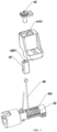
- the rehabilitation exercise equipment comprises at least two rope transmission devices and at least two link mechanisms, and rotation axes that the rope winding shafts in the two rope transmission devices rotate around are perpendicular to each other; the limb fixing assembly is fixed to the oscillating piece of one of the rope transmission devices by one link mechanism, and the limb fixing assembly is fixed to the oscillating piece of the other rope transmission device by the other link mechanism.
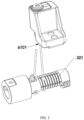
- the rehabilitation exercise equipment comprises at least a rope transmission device 100 and a limb fixing assembly 300.
- the limb movement assembly 300 is connected to the rope transmission device 100 such that the spatial position of the limb movement assembly 300 can be adjusted when the rope transmission device 100 is in operation.
- the rope transmission device 100 since the limb fixing assembly 300 is carried by the rope of the rope transmission device 100, the rope transmission device 100 has little noise during the operation and when the limb fixing assembly 300 is driven, it can move gently.
- the rope transmission device 100 includes a device main body 10, a transmission assembly 20, a rope winding shaft 30, at least two ropes 40, and an oscillating piece 50.
- the rope 40 is implemented to be made of a metallic material.
- the rope 40 is a steel wire rope.
- the rope winding shaft 30 is rotatably connected to the transmission assembly 20 and mounted to the device main body 10.
- the oscillating piece 50 is swingably supported to the device main body 10 by two of the ropes 40.
- the rope winding shaft 30 is rotatably connected to an output shaft of the transmission assembly 20 such that the rope winding shaft 30 can be rotated driven by the transmission assembly 20. It is understandable that where the transmission assembly 20 is embodied as a motor, the rope winding shaft 30 may be embodied as the output shaft of the motor.
- the peripheral edge of the outer wall of the rope winding shaft 30 is provided with at least one continuous rope winding spiral groove 301.
- the rope winding spiral groove 301 has an inner end proximal to the transmission assembly 20 and an outer end distal to the transmission assembly 20. After one end of one of the ropes, 40 is fixed, it is partially wound in a part of the groove near the inner end of the rope winding spiral groove 301 of the rope winding shaft 30, and the rope 40 is further fixed to one end of the oscillating piece 50 around the circumference that the oscillating piece 50 oscillates.
- the oscillating piece 50 is mounted at the device main body 10 in such a manner that an oscillation axis around which the oscillating piece 50 oscillates is collinear with the rotation axis of the rope winding shaft 30.
- the oscillating piece 50 can oscillate back and forth on the device main body 10. It is worth mentioning that the limb fixing assembly 300 is mounted to the oscillating piece 50 such that when the oscillating piece 50 oscillates, the limb fixing assembly 300 follows the oscillating piece 50 in a synchronized motion.
- the distances between two adjacent groove bodies of the rope winding spiral groove 301 are equal so that the oscillating piece 50 can gently oscillate. Therefore, the limb fixing assembly 300 connected to the oscillating piece 50 does not move violently, thereby effectively preventing the user from being injured due to the unstable movement of the transmission mechanism during the rehabilitation training.
- the oscillating piece 50 has a circular arc outer wall portion 51 and at least one radial connecting portion 52 connected to the circular arc outer wall portion 51.
- the radial connecting portion 52 is rotatably mounted to the device main body 10.
- the rope transmission device 100 comprises a rope tightener 60.
- Each of the ropes 40 is connected to the rope tightener 60 in a way that can be tightened so that the ropes 40 can be tightened by the rope tightener 60.
- Two ends of the circular arc outer wall portion 51 are respectively provided with a rope tightener 60 for respectively fixing one rope 40. That is, one end of the rope 40 is fixed to the rope tightener 60 provided at one end of the circular arc outer wall portion 51. The other rope 40 is fixed to the rope tightener 60 provided at the other end of the circular arc outer wall portion 51. Both of the ropes 40 are wound out and wound in from the outer wall of the circular arc outer wall portion 51 during the process that the swinging member 50 is driven to oscillate.
- the outer wall of the circular arc outer wall portion 51 is provided with a limiting groove 5101 to prevent the rope 40 from slipping off when the two ropes 40 are wound out and wound in the outer wall of the circular arc outer wall portion 51.
- Each of the ropes 40 is connected to the rope tightener 60 that can be tightened in a tangential direction tangential to the circular arc outer wall portion 51. It could be understood that the rope 40 has some extensibility. Therefore, when the rope transmission device 100 is continuously operated for a certain time, the tension of the rope 40 is weakened. If the tension of the rope 40 continues to weaken, the rope 40 will be too loose and may be in one groove body of the rope winding spiral groove 301, i.e., the rope 40 that should have been wound in two adjacent groove bodies will be wound into the same groove body. This causes the oscillating piece 50 on the rope transmission device 100 to oscillate unevenly and it may even not work normally.
- the rope 40 is connected to the rope tightener 60 in a way that can be tightened in a tangential direction tangential to the circular arc outer wall portion 51, such that when the tension of the rope 40 decreases, the rope 40 can be tightened by the rope tightener 60.
- the rope 40 since the rope 40 is maintained within a predetermined tension range when the rope 40 is wounded and unwounded, the rope 40 can be always guided into the rope winding spiral groove 301, thereby ensuring the transmission stability of the rope transmission device 100.
- the rope tightener 60 includes a base 61, a moving block 62, and a tightness adjusting piece 63.
- the base 61 is fixed to one end of the circular arc outer wall portion 51 of the oscillating piece 50.
- the base 61 is provided thereon with a perforation 6101 extending in a tangential direction tangential to the outer wall of the circular arc outer wall portion 51.
- the moving block 62 can be slidably connected to the base 61 in a direction in which the perforation 6101 extends.
- the moving block 62 is connected to the tightness adjusting piece 63 in a way that can be driven.
- each of the ropes 40 is fixed to the moving block 62 after passing through the perforation 6101.
- the moving block 62 can be enabled to slide in the direction of tightening the rope 40.
- the tightness of the rope 40 needs to be lowered, that is, the tension of the rope 40 is reduced, the moving block 62 can be enabled to slide in the direction of releasing the rope 40 by operating the tightness adjusting piece 63.
- the tightness adjusting piece 63 is embodied as a rotatable screw, and the moving block 62 is correspondingly provided with a threaded hole matching the screw.
- the extending direction of the threaded hole is parallel to the direction in which the moving block 62 moves, so that the moving block 62 can always move in a tangential direction tangential to the outer wall of the circular arc outer wall portion 51 when the tightness adjusting piece 63 is operated.
- the base 61 is formed with a perforation 6102 communicating with the perforation 6101.
- the moving block 62 is slidably mounted to the perforation 6102.
- the moving block 62 is provided with a mounting hole 6201 in a tangential direction tangent to the outer wall of the circular arc outer wall portion 51.
- the rope 40 is limited by the moving block 62 after passing through the perforation 6101 and the mounting hole 6201 on the moving block 62. It is worth mentioning that the aperture of the mounting hole 6201 is larger than the aperture of the perforation 6101, so that when the rope 40 is moved by the moving block 62, the rope 40 does not rotate but slides only in a direction tangential to the circular arc outer wall portion 51.
- the rehabilitation exercise equipment includes at least two rope transmission devices 100 and at least two link mechanisms 500.
- the rotation axes that rope winding shafts 30 in the two rope transmission devices 100 rotate around are perpendicular to each other.
- the limb fixing assembly 300 is fixed to the oscillating piece 50 of one rope transmission device by one link mechanism 500, and the limb fixing assembly 300 is fixed to the oscillating piece of the other rope transmission device by the other link mechanism 500.
Landscapes
- Health & Medical Sciences (AREA)
- General Engineering & Computer Science (AREA)
- Engineering & Computer Science (AREA)
- General Health & Medical Sciences (AREA)
- Physical Education & Sports Medicine (AREA)
- Life Sciences & Earth Sciences (AREA)
- Orthopedic Medicine & Surgery (AREA)
- Mechanical Engineering (AREA)
- Biophysics (AREA)
- Epidemiology (AREA)
- Animal Behavior & Ethology (AREA)
- Public Health (AREA)
- Veterinary Medicine (AREA)
- Rehabilitation Therapy (AREA)
- Pain & Pain Management (AREA)
- Transmission Devices (AREA)
- Rehabilitation Tools (AREA)
Claims (9)
- Seilübertragungsvorrichtung (100) zum Antrieb einer Gliedmaßenbefestigungsanordnung (300), wobei die Seilübertragungsvorrichtung (100) Folgendes umfasst:einen Vorrichtungshauptkörper (10);eine Übertragungsbaugruppe (20), wobei die Übertragungsbaugruppe (20) am Vorrichtungshauptkörper (10) vorgesehen ist;eine Seilwickelwelle (30), wobei die Seilwickelwelle (30) drehbar mit der Übertragungsbaugruppe (20) verbunden ist und mindestens eine kontinuierliche Seilwickelspiralrille (301) entlang einer Umfangskante einer Außenwand der Seilwickelwelle (30) vorgesehen ist, wobei die Seilwickelwelle (30) ein inneres Ende, das nahe der Übertragungsbaugruppe (20) liegt, und ein äußeres Ende, das entfernt von der Übertragungsbaugruppe (20) ist, aufweist;ein oszillierendes Teil (50) zum Antreiben der Gliedmaßenbefestigungsanordnung (300), wobei das oszillierende Teil (50) an dem Vorrichtungshauptkörper (10) derart vorgesehen ist, dass eine oszillierende Welle, um die das oszillierende Teil (50) oszilliert, kollinear mit einer Drehwelle der Seilwickelwelle (30) ist;zwei Seile (40), wobei ein Ende eines der Seile (40) an der Seilwickelwelle (30) befestigt ist und es teilweise in einem Abschnitt einer Rille in der Nähe des inneren Endes der Seilwickelspiralrille (301) der Seilwickelwelle (30) aufgewickelt ist, und das Seil (40) weiter an einem Ende des oszillierenden Teils (50) um einen Umfang befestigt ist, den das oszillierende Teil (50) schwingt; nachdem ein Ende des anderen Seils (50) befestigt ist, wird es teilweise in einen Abschnitt der Rille in der Nähe der Seilwickelspiralrille (301) gewickelt, und das Seil wird am anderen Ende des oszillierenden Teils (50) um den Umfang herum befestigt, den das oszillierende Teil (50) schwingt;dadurch gekennzeichnet, dassdie Seilübertragungsvorrichtung (100) zwei Seilspanner (60) aufweist, und das oszillierende Teil (50) einen kreisbogenförmigen Außenwandabschnitt (51) und mindestens einen mit dem kreisbogenförmigen Außenwandabschnitt (51) verbundenen radialen Verbindungsabschnitt (52) aufweist, wobei der radiale Verbindungsabschnitt (52) dazu vorgesehen ist, um die Oszillationsachse drehbar am Vorrichtungshauptkörper (10) gelagert zu werden, wobei jedes der Seile (40) jeweils mit einem Seilspanner (60) so verbunden ist, dass es in einer tangentialen Richtung tangential zum kreisbogenförmigen Außenwandabschnitt (51) gespannt werden kann.
- Seilübertragungsvorrichtung (100) nach Anspruch 1, wobei die Abstände zwischen zwei benachbarten Rillenkörpern der Seilwickelspiralrille (301) gleich sind.
- Seilübertragungsvorrichtung (100) nach Anspruch 1, wobei die Übertragungsbaugruppe (20) als Motor ausgebildet ist und die Seilwickelwelle als Abtriebswelle des Motors ausgebildet ist.
- Seilübertragungsvorrichtung (100) nach Anspruch 1, wobei die Seilspanner (60) an zwei Enden des oszillierenden Teils (50) montiert sind.
- Seilübertragungsvorrichtung (100) nach Anspruch 4, wobei der Seilspanner (60) eine Basis (61), einen beweglichen Block (62) und ein Straffheitseinstellteil (63) umfasst, wobei die Basis (61) an einem Ende des kreisbogenförmigen Außenwandabschnitts (51) des oszillierenden Teils (50) befestigt ist, und die Basis (61) mit einer Perforation (6101) versehen ist, die sich in einer tangentialen Richtung tangential zu der Außenwand des kreisbogenförmigen Außenwandabschnitts (51) erstreckt, wobei der bewegliche Block (62) gleitend mit der Basis (61) in einer Richtung verbunden werden kann, in der sich die Perforation (6101) erstreckt, und der bewegliche Block (62) mit dem Straffheitseinstellteil (63) in einer Weise verbunden ist, dass er angetrieben werden kann.
- Seilübertragungsvorrichtung (100) nach Anspruch 5, wobei das Straffheitseinstellteil (63) als drehbare Schraube ausgebildet ist und der bewegliche Block (62) entsprechend mit einer zu der Schraube passenden Gewindebohrung versehen ist, wobei sich die Gewindebohrung in einer Richtung parallel zu der Richtung erstreckt, in der sich der bewegliche Block (62) bewegt.
- Seilübertragungsvorrichtung (100) nach Anspruch 6, wobei die Basis (61) einen verschiebbaren Hohlraum bildet, der bewegliche Block (62) verschiebbar in dem verschiebbaren Hohlraum montiert ist, der bewegliche Block mit einem Montageloch (6201) in einer tangentialen Richtung tangential zu der Außenwand des kreisbogenförmigen Außenwandabschnitts (51) versehen ist, das Seil (40) durch den beweglichen Block (62) begrenzt wird, nachdem es durch die Perforation (6101) und das Montageloch (6201) auf dem beweglichen Block (62) hindurchgegangen ist, und eine Öffnung des Montagelochs (62) größer als die Öffnung der Perforation (6101) ist.
- Rehabilitationsübungsgerät, wobei das Rehabilitationsübungsgerät umfasst:die Seilübertragungsvorrichtung (100) nach einem der Ansprüche 1 bis 7; undeine Gliedmaßenbefestigungsanordnung (300), wobei die Gliedmaßenbefestigungsanordnung (300) mit dem oszillierenden Teil (50) der Seilübertragungsvorrichtung (100) verbunden ist.
- Rehabilitationsübungsgerät nach Anspruch 8, wobei das Rehabilitationsübungsgerät mindestens zwei Seilübertragungsvorrichtungen (100) und mindestens zwei Verbindungsmechanismen (500) umfasst, und die Rotationsachsen, um die sich die Seilwickelwellen (30) in den beiden Seilübertragungsvorrichtungen (100) drehen, senkrecht zueinander verlaufen; die Gliedmaßenbefestigungsanordnung (300) an dem oszillierenden Teil (50) einer der Seilübertragungsvorrichtungen (100) durch einen Verbindungsmechanismus (500) befestigt ist, und die Gliedmaßenbefestigungsanordnung (300) an dem oszillierenden Teil (50) der anderen Seilübertragungsvorrichtung (100) durch den anderen Verbindungsmechanismus (500) befestigt ist.
Applications Claiming Priority (2)
| Application Number | Priority Date | Filing Date | Title |
|---|---|---|---|
| CN202111054392.6A CN113669425B (zh) | 2021-09-09 | 2021-09-09 | 一种康复运动设备和绳传动装置 |
| PCT/CN2022/114481 WO2023035946A1 (zh) | 2021-09-09 | 2022-08-24 | 一种康复运动设备和绳传动装置 |
Publications (3)
| Publication Number | Publication Date |
|---|---|
| EP4234978A1 EP4234978A1 (de) | 2023-08-30 |
| EP4234978A4 EP4234978A4 (de) | 2024-08-14 |
| EP4234978B1 true EP4234978B1 (de) | 2025-01-22 |
Family
ID=78549105
Family Applications (1)
| Application Number | Title | Priority Date | Filing Date |
|---|---|---|---|
| EP22866416.5A Active EP4234978B1 (de) | 2021-09-09 | 2022-08-24 | Rehabilitationsübungsvorrichtung und seilübertragungsvorrichtung |
Country Status (4)
| Country | Link |
|---|---|
| US (1) | US20230293377A1 (de) |
| EP (1) | EP4234978B1 (de) |
| CN (1) | CN113669425B (de) |
| WO (1) | WO2023035946A1 (de) |
Families Citing this family (1)
| Publication number | Priority date | Publication date | Assignee | Title |
|---|---|---|---|---|
| CN113669425B (zh) * | 2021-09-09 | 2022-09-30 | 上海傅利叶智能科技有限公司 | 一种康复运动设备和绳传动装置 |
Family Cites Families (20)
| Publication number | Priority date | Publication date | Assignee | Title |
|---|---|---|---|---|
| US5105672A (en) * | 1990-05-17 | 1992-04-21 | Carson Donald G | Rotary drive apparatus having one member with smooth outer peripheral surface |
| AU2003256604A1 (en) * | 2003-07-17 | 2005-03-07 | David Varner | Sports training apparatus |
| DE102005038309A1 (de) * | 2005-08-11 | 2007-02-15 | Olaf Krell | Übungsgerät |
| EP2505233B1 (de) * | 2011-03-25 | 2019-11-06 | Martin Hofele | Muskulatur-Trimmgerät |
| FR2993333B1 (fr) * | 2012-07-11 | 2014-08-22 | Commissariat Energie Atomique | Dispositif de transmission de mouvement a reducteur epicycloidal, reducteur epicycloidal et bras de manipulation |
| CN105979919B (zh) * | 2013-09-27 | 2019-09-20 | 埃斯顿(南京)医疗科技有限公司 | 多活动轴线的非外骨骼式康复设备 |
| US12447089B2 (en) * | 2013-09-27 | 2025-10-21 | Barrett Technology, Llc | Multi-active-axis, non-exoskeletal robotic rehabilitation device |
| CN104784889B (zh) * | 2015-04-30 | 2017-06-16 | 安阳市翔宇医疗设备有限责任公司 | 一种上肢康复训练器 |
| CN105972170B (zh) * | 2016-06-13 | 2019-10-29 | 北京理工大学 | 一种绳驱动外骨骼机械臂的绳传动滑轮 |
| CN107041804B (zh) * | 2017-05-03 | 2023-07-11 | 郑州飞龙医疗设备有限公司 | 一种头部康复系统及其制成的多功能颈椎分型治疗机 |
| EP3723943B1 (de) * | 2017-12-11 | 2023-06-07 | Sze Kit Ho | Antriebsanordnung für ein bewegliches körperteil |
| CN209204563U (zh) * | 2018-11-12 | 2019-08-06 | 佛山市高明区人民医院 | 一种膝关节康复训练装置 |
| CN109620637A (zh) * | 2018-12-16 | 2019-04-16 | 北京工业大学 | 一种用于柔性助力外衣的单关节双侧驱动装置 |
| CN211986906U (zh) * | 2020-03-12 | 2020-11-24 | 汤恒毅 | 主动阻力式健身器材、系统及复合式健身器材 |
| CN212347600U (zh) * | 2020-03-17 | 2021-01-15 | 河南省儿童医院郑州儿童医院 | 小儿上肢肌力及关节康复训练装置 |
| CN112594347A (zh) * | 2020-12-11 | 2021-04-02 | 洛阳理工学院 | 一种可实现无级调节的区间恒力装置 |
| CN112933535A (zh) * | 2021-02-02 | 2021-06-11 | 杭州程天科技发展有限公司 | 多部位联动协作锻炼的辅助康复装置 |
| CN216148976U (zh) * | 2021-09-09 | 2022-04-01 | 上海傅利叶智能科技有限公司 | 一种康复训练设备 |
| CN216158213U (zh) * | 2021-09-09 | 2022-04-01 | 上海傅利叶智能科技有限公司 | 一种绳传动装置 |
| CN113669425B (zh) * | 2021-09-09 | 2022-09-30 | 上海傅利叶智能科技有限公司 | 一种康复运动设备和绳传动装置 |
-
2021
- 2021-09-09 CN CN202111054392.6A patent/CN113669425B/zh active Active
-
2022
- 2022-08-24 WO PCT/CN2022/114481 patent/WO2023035946A1/zh not_active Ceased
- 2022-08-24 EP EP22866416.5A patent/EP4234978B1/de active Active
-
2023
- 2023-05-24 US US18/322,752 patent/US20230293377A1/en active Pending
Also Published As
| Publication number | Publication date |
|---|---|
| CN113669425B (zh) | 2022-09-30 |
| US20230293377A1 (en) | 2023-09-21 |
| WO2023035946A1 (zh) | 2023-03-16 |
| CN113669425A (zh) | 2021-11-19 |
| EP4234978A4 (de) | 2024-08-14 |
| EP4234978A1 (de) | 2023-08-30 |
Similar Documents
| Publication | Publication Date | Title |
|---|---|---|
| JP6153484B2 (ja) | ワイヤ駆動装置およびマニピュレータ | |
| US11179258B2 (en) | Limb motion support device | |
| EP4234978B1 (de) | Rehabilitationsübungsvorrichtung und seilübertragungsvorrichtung | |
| US8082910B1 (en) | Pulley assembly for a compound archery bow | |
| US4790301A (en) | Device for and method of dynamic splinting | |
| US8757691B2 (en) | Hand and robot | |
| US12263583B2 (en) | Counterbalance mechanism including drive ratio | |
| JP2020524059A (ja) | 腕を動かすための装置および装置を操作する方法 | |
| JP2008067852A (ja) | 上肢手指機能回復訓練装置 | |
| US20030087735A1 (en) | Pull cord exerciser | |
| CN216158213U (zh) | 一种绳传动装置 | |
| CN117017603A (zh) | 一种创伤骨科用固定装置 | |
| CN219089638U (zh) | 俯仰驱动部件以及装配有该俯仰驱动部件的远心机构 | |
| US9995379B2 (en) | Driving module and motion assistance apparatus including the same | |
| KR102084168B1 (ko) | 어깨 재활로봇 | |
| CN220293658U (zh) | 主控制手用传动系统、主控制手及手术机器人 | |
| JP2006192523A (ja) | 多関節指機構 | |
| KR101179491B1 (ko) | 전동보조기용 구동장치 | |
| CN116650130B (zh) | 主控制手用传动系统、主控制手及手术机器人 | |
| CN109568090A (zh) | 一种可跳跃的下肢外骨骼 | |
| CN214342839U (zh) | 具有多齿轮的关节康复训练器 | |
| CN216148976U (zh) | 一种康复训练设备 | |
| CN116965934A (zh) | 机械臂、关节结构和手术机器人 | |
| CN117653338A (zh) | 远心机构以及装配有该远心机构的手术机器人 | |
| CN211862882U (zh) | 用于吻合器的柔性摆头装置 |
Legal Events
| Date | Code | Title | Description |
|---|---|---|---|
| STAA | Information on the status of an ep patent application or granted ep patent |
Free format text: STATUS: THE INTERNATIONAL PUBLICATION HAS BEEN MADE |
|
| PUAI | Public reference made under article 153(3) epc to a published international application that has entered the european phase |
Free format text: ORIGINAL CODE: 0009012 |
|
| STAA | Information on the status of an ep patent application or granted ep patent |
Free format text: STATUS: REQUEST FOR EXAMINATION WAS MADE |
|
| 17P | Request for examination filed |
Effective date: 20230526 |
|
| AK | Designated contracting states |
Kind code of ref document: A1 Designated state(s): AL AT BE BG CH CY CZ DE DK EE ES FI FR GB GR HR HU IE IS IT LI LT LU LV MC MK MT NL NO PL PT RO RS SE SI SK SM TR |
|
| STAA | Information on the status of an ep patent application or granted ep patent |
Free format text: STATUS: EXAMINATION IS IN PROGRESS |
|
| A4 | Supplementary search report drawn up and despatched |
Effective date: 20240711 |
|
| RIC1 | Information provided on ipc code assigned before grant |
Ipc: F16H 19/00 20060101ALI20240705BHEP Ipc: A63B 23/035 20060101ALI20240705BHEP Ipc: F16H 37/12 20060101ALI20240705BHEP Ipc: F16H 19/08 20060101AFI20240705BHEP |
|
| 17Q | First examination report despatched |
Effective date: 20240730 |
|
| GRAP | Despatch of communication of intention to grant a patent |
Free format text: ORIGINAL CODE: EPIDOSNIGR1 |
|
| STAA | Information on the status of an ep patent application or granted ep patent |
Free format text: STATUS: GRANT OF PATENT IS INTENDED |
|
| RIC1 | Information provided on ipc code assigned before grant |
Ipc: F16H 19/00 20060101ALI20241024BHEP Ipc: A63B 23/035 20060101ALI20241024BHEP Ipc: F16H 37/12 20060101ALI20241024BHEP Ipc: F16H 19/08 20060101AFI20241024BHEP |
|
| GRAS | Grant fee paid |
Free format text: ORIGINAL CODE: EPIDOSNIGR3 |
|
| DAV | Request for validation of the european patent (deleted) | ||
| DAX | Request for extension of the european patent (deleted) | ||
| INTG | Intention to grant announced |
Effective date: 20241107 |
|
| GRAA | (expected) grant |
Free format text: ORIGINAL CODE: 0009210 |
|
| STAA | Information on the status of an ep patent application or granted ep patent |
Free format text: STATUS: THE PATENT HAS BEEN GRANTED |
|
| P01 | Opt-out of the competence of the unified patent court (upc) registered |
Free format text: CASE NUMBER: APP_64645/2024 Effective date: 20241206 |
|
| AK | Designated contracting states |
Kind code of ref document: B1 Designated state(s): AL AT BE BG CH CY CZ DE DK EE ES FI FR GB GR HR HU IE IS IT LI LT LU LV MC MK MT NL NO PL PT RO RS SE SI SK SM TR |
|
| REG | Reference to a national code |
Ref country code: GB Ref legal event code: FG4D |
|
| REG | Reference to a national code |
Ref country code: CH Ref legal event code: EP |
|
| REG | Reference to a national code |
Ref country code: IE Ref legal event code: FG4D |
|
| REG | Reference to a national code |
Ref country code: DE Ref legal event code: R096 Ref document number: 602022009876 Country of ref document: DE |
|
| REG | Reference to a national code |
Ref country code: NL Ref legal event code: MP Effective date: 20250122 |
|
| PG25 | Lapsed in a contracting state [announced via postgrant information from national office to epo] |
Ref country code: NL Free format text: LAPSE BECAUSE OF FAILURE TO SUBMIT A TRANSLATION OF THE DESCRIPTION OR TO PAY THE FEE WITHIN THE PRESCRIBED TIME-LIMIT Effective date: 20250122 |
|
| PG25 | Lapsed in a contracting state [announced via postgrant information from national office to epo] |
Ref country code: RS Free format text: LAPSE BECAUSE OF FAILURE TO SUBMIT A TRANSLATION OF THE DESCRIPTION OR TO PAY THE FEE WITHIN THE PRESCRIBED TIME-LIMIT Effective date: 20250422 |
|
| PG25 | Lapsed in a contracting state [announced via postgrant information from national office to epo] |
Ref country code: FI Free format text: LAPSE BECAUSE OF FAILURE TO SUBMIT A TRANSLATION OF THE DESCRIPTION OR TO PAY THE FEE WITHIN THE PRESCRIBED TIME-LIMIT Effective date: 20250122 |
|
| PG25 | Lapsed in a contracting state [announced via postgrant information from national office to epo] |
Ref country code: PL Free format text: LAPSE BECAUSE OF FAILURE TO SUBMIT A TRANSLATION OF THE DESCRIPTION OR TO PAY THE FEE WITHIN THE PRESCRIBED TIME-LIMIT Effective date: 20250122 |
|
| PG25 | Lapsed in a contracting state [announced via postgrant information from national office to epo] |
Ref country code: ES Free format text: LAPSE BECAUSE OF FAILURE TO SUBMIT A TRANSLATION OF THE DESCRIPTION OR TO PAY THE FEE WITHIN THE PRESCRIBED TIME-LIMIT Effective date: 20250122 |
|
| REG | Reference to a national code |
Ref country code: LT Ref legal event code: MG9D |
|
| PG25 | Lapsed in a contracting state [announced via postgrant information from national office to epo] |
Ref country code: NO Free format text: LAPSE BECAUSE OF FAILURE TO SUBMIT A TRANSLATION OF THE DESCRIPTION OR TO PAY THE FEE WITHIN THE PRESCRIBED TIME-LIMIT Effective date: 20250422 Ref country code: IS Free format text: LAPSE BECAUSE OF FAILURE TO SUBMIT A TRANSLATION OF THE DESCRIPTION OR TO PAY THE FEE WITHIN THE PRESCRIBED TIME-LIMIT Effective date: 20250522 |
|
| REG | Reference to a national code |
Ref country code: AT Ref legal event code: MK05 Ref document number: 1761678 Country of ref document: AT Kind code of ref document: T Effective date: 20250122 |
|
| PG25 | Lapsed in a contracting state [announced via postgrant information from national office to epo] |
Ref country code: HR Free format text: LAPSE BECAUSE OF FAILURE TO SUBMIT A TRANSLATION OF THE DESCRIPTION OR TO PAY THE FEE WITHIN THE PRESCRIBED TIME-LIMIT Effective date: 20250122 |
|
| PG25 | Lapsed in a contracting state [announced via postgrant information from national office to epo] |
Ref country code: PT Free format text: LAPSE BECAUSE OF FAILURE TO SUBMIT A TRANSLATION OF THE DESCRIPTION OR TO PAY THE FEE WITHIN THE PRESCRIBED TIME-LIMIT Effective date: 20250522 Ref country code: LV Free format text: LAPSE BECAUSE OF FAILURE TO SUBMIT A TRANSLATION OF THE DESCRIPTION OR TO PAY THE FEE WITHIN THE PRESCRIBED TIME-LIMIT Effective date: 20250122 |
|
| PG25 | Lapsed in a contracting state [announced via postgrant information from national office to epo] |
Ref country code: GR Free format text: LAPSE BECAUSE OF FAILURE TO SUBMIT A TRANSLATION OF THE DESCRIPTION OR TO PAY THE FEE WITHIN THE PRESCRIBED TIME-LIMIT Effective date: 20250423 Ref country code: BG Free format text: LAPSE BECAUSE OF FAILURE TO SUBMIT A TRANSLATION OF THE DESCRIPTION OR TO PAY THE FEE WITHIN THE PRESCRIBED TIME-LIMIT Effective date: 20250122 |
|
| PG25 | Lapsed in a contracting state [announced via postgrant information from national office to epo] |
Ref country code: AT Free format text: LAPSE BECAUSE OF FAILURE TO SUBMIT A TRANSLATION OF THE DESCRIPTION OR TO PAY THE FEE WITHIN THE PRESCRIBED TIME-LIMIT Effective date: 20250122 |
|
| PG25 | Lapsed in a contracting state [announced via postgrant information from national office to epo] |
Ref country code: SE Free format text: LAPSE BECAUSE OF FAILURE TO SUBMIT A TRANSLATION OF THE DESCRIPTION OR TO PAY THE FEE WITHIN THE PRESCRIBED TIME-LIMIT Effective date: 20250122 |
|
| PG25 | Lapsed in a contracting state [announced via postgrant information from national office to epo] |
Ref country code: SM Free format text: LAPSE BECAUSE OF FAILURE TO SUBMIT A TRANSLATION OF THE DESCRIPTION OR TO PAY THE FEE WITHIN THE PRESCRIBED TIME-LIMIT Effective date: 20250122 |
|
| PG25 | Lapsed in a contracting state [announced via postgrant information from national office to epo] |
Ref country code: DK Free format text: LAPSE BECAUSE OF FAILURE TO SUBMIT A TRANSLATION OF THE DESCRIPTION OR TO PAY THE FEE WITHIN THE PRESCRIBED TIME-LIMIT Effective date: 20250122 |
|
| PGFP | Annual fee paid to national office [announced via postgrant information from national office to epo] |
Ref country code: DE Payment date: 20250827 Year of fee payment: 4 |
|
| PG25 | Lapsed in a contracting state [announced via postgrant information from national office to epo] |
Ref country code: IT Free format text: LAPSE BECAUSE OF FAILURE TO SUBMIT A TRANSLATION OF THE DESCRIPTION OR TO PAY THE FEE WITHIN THE PRESCRIBED TIME-LIMIT Effective date: 20250122 |
|
| PGFP | Annual fee paid to national office [announced via postgrant information from national office to epo] |
Ref country code: FR Payment date: 20250826 Year of fee payment: 4 |
|
| PG25 | Lapsed in a contracting state [announced via postgrant information from national office to epo] |
Ref country code: CZ Free format text: LAPSE BECAUSE OF FAILURE TO SUBMIT A TRANSLATION OF THE DESCRIPTION OR TO PAY THE FEE WITHIN THE PRESCRIBED TIME-LIMIT Effective date: 20250122 Ref country code: EE Free format text: LAPSE BECAUSE OF FAILURE TO SUBMIT A TRANSLATION OF THE DESCRIPTION OR TO PAY THE FEE WITHIN THE PRESCRIBED TIME-LIMIT Effective date: 20250122 |
|
| REG | Reference to a national code |
Ref country code: DE Ref legal event code: R097 Ref document number: 602022009876 Country of ref document: DE |
|
| PG25 | Lapsed in a contracting state [announced via postgrant information from national office to epo] |
Ref country code: RO Free format text: LAPSE BECAUSE OF FAILURE TO SUBMIT A TRANSLATION OF THE DESCRIPTION OR TO PAY THE FEE WITHIN THE PRESCRIBED TIME-LIMIT Effective date: 20250122 |
|
| PG25 | Lapsed in a contracting state [announced via postgrant information from national office to epo] |
Ref country code: SK Free format text: LAPSE BECAUSE OF FAILURE TO SUBMIT A TRANSLATION OF THE DESCRIPTION OR TO PAY THE FEE WITHIN THE PRESCRIBED TIME-LIMIT Effective date: 20250122 |
|
| PLBE | No opposition filed within time limit |
Free format text: ORIGINAL CODE: 0009261 |
|
| STAA | Information on the status of an ep patent application or granted ep patent |
Free format text: STATUS: NO OPPOSITION FILED WITHIN TIME LIMIT |
|
| REG | Reference to a national code |
Ref country code: CH Ref legal event code: L10 Free format text: ST27 STATUS EVENT CODE: U-0-0-L10-L00 (AS PROVIDED BY THE NATIONAL OFFICE) Effective date: 20251203 |
|
| 26N | No opposition filed |
Effective date: 20251023 |
|
| REG | Reference to a national code |
Ref country code: CH Ref legal event code: H13 Free format text: ST27 STATUS EVENT CODE: U-0-0-H10-H13 (AS PROVIDED BY THE NATIONAL OFFICE) Effective date: 20260324 |
|
| PG25 | Lapsed in a contracting state [announced via postgrant information from national office to epo] |
Ref country code: MC Free format text: LAPSE BECAUSE OF FAILURE TO SUBMIT A TRANSLATION OF THE DESCRIPTION OR TO PAY THE FEE WITHIN THE PRESCRIBED TIME-LIMIT Effective date: 20250122 |
|
| PG25 | Lapsed in a contracting state [announced via postgrant information from national office to epo] |
Ref country code: LU Free format text: LAPSE BECAUSE OF NON-PAYMENT OF DUE FEES Effective date: 20250824 |