EP4234932A2 - Scrollpumpe mit verbessertem zugang zum ansaugbereich zu montagezwecken - Google Patents
Scrollpumpe mit verbessertem zugang zum ansaugbereich zu montagezwecken Download PDFInfo
- Publication number
- EP4234932A2 EP4234932A2 EP23179555.0A EP23179555A EP4234932A2 EP 4234932 A2 EP4234932 A2 EP 4234932A2 EP 23179555 A EP23179555 A EP 23179555A EP 4234932 A2 EP4234932 A2 EP 4234932A2
- Authority
- EP
- European Patent Office
- Prior art keywords
- spiral
- support plate
- housing
- scroll pump
- orbiter
- Prior art date
- Legal status (The legal status is an assumption and is not a legal conclusion. Google has not performed a legal analysis and makes no representation as to the accuracy of the status listed.)
- Granted
Links
Images


Classifications
-
- F—MECHANICAL ENGINEERING; LIGHTING; HEATING; WEAPONS; BLASTING
- F04—POSITIVE - DISPLACEMENT MACHINES FOR LIQUIDS; PUMPS FOR LIQUIDS OR ELASTIC FLUIDS
- F04C—ROTARY-PISTON, OR OSCILLATING-PISTON, POSITIVE-DISPLACEMENT MACHINES FOR LIQUIDS; ROTARY-PISTON, OR OSCILLATING-PISTON, POSITIVE-DISPLACEMENT PUMPS
- F04C18/00—Rotary-piston pumps specially adapted for elastic fluids
- F04C18/02—Rotary-piston pumps specially adapted for elastic fluids of arcuate-engagement type, i.e. with circular translatory movement of co-operating members, each member having the same number of teeth or tooth-equivalents
- F04C18/0207—Rotary-piston pumps specially adapted for elastic fluids of arcuate-engagement type, i.e. with circular translatory movement of co-operating members, each member having the same number of teeth or tooth-equivalents both members having co-operating elements in spiral form
- F04C18/0215—Rotary-piston pumps specially adapted for elastic fluids of arcuate-engagement type, i.e. with circular translatory movement of co-operating members, each member having the same number of teeth or tooth-equivalents both members having co-operating elements in spiral form where only one member is moving
-
- F—MECHANICAL ENGINEERING; LIGHTING; HEATING; WEAPONS; BLASTING
- F04—POSITIVE - DISPLACEMENT MACHINES FOR LIQUIDS; PUMPS FOR LIQUIDS OR ELASTIC FLUIDS
- F04C—ROTARY-PISTON, OR OSCILLATING-PISTON, POSITIVE-DISPLACEMENT MACHINES FOR LIQUIDS; ROTARY-PISTON, OR OSCILLATING-PISTON, POSITIVE-DISPLACEMENT PUMPS
- F04C18/00—Rotary-piston pumps specially adapted for elastic fluids
- F04C18/02—Rotary-piston pumps specially adapted for elastic fluids of arcuate-engagement type, i.e. with circular translatory movement of co-operating members, each member having the same number of teeth or tooth-equivalents
- F04C18/0207—Rotary-piston pumps specially adapted for elastic fluids of arcuate-engagement type, i.e. with circular translatory movement of co-operating members, each member having the same number of teeth or tooth-equivalents both members having co-operating elements in spiral form
- F04C18/0246—Details concerning the involute wraps or their base, e.g. geometry
- F04C18/0253—Details concerning the base
-
- F—MECHANICAL ENGINEERING; LIGHTING; HEATING; WEAPONS; BLASTING
- F04—POSITIVE - DISPLACEMENT MACHINES FOR LIQUIDS; PUMPS FOR LIQUIDS OR ELASTIC FLUIDS
- F04C—ROTARY-PISTON, OR OSCILLATING-PISTON, POSITIVE-DISPLACEMENT MACHINES FOR LIQUIDS; ROTARY-PISTON, OR OSCILLATING-PISTON, POSITIVE-DISPLACEMENT PUMPS
- F04C23/00—Combinations of two or more pumps, each being of rotary-piston or oscillating-piston type, specially adapted for elastic fluids; Pumping installations specially adapted for elastic fluids; Multi-stage pumps specially adapted for elastic fluids
- F04C23/008—Hermetic pumps
-
- F—MECHANICAL ENGINEERING; LIGHTING; HEATING; WEAPONS; BLASTING
- F04—POSITIVE - DISPLACEMENT MACHINES FOR LIQUIDS; PUMPS FOR LIQUIDS OR ELASTIC FLUIDS
- F04C—ROTARY-PISTON, OR OSCILLATING-PISTON, POSITIVE-DISPLACEMENT MACHINES FOR LIQUIDS; ROTARY-PISTON, OR OSCILLATING-PISTON, POSITIVE-DISPLACEMENT PUMPS
- F04C25/00—Adaptations of pumps for special use of pumps for elastic fluids
- F04C25/02—Adaptations of pumps for special use of pumps for elastic fluids for producing high vacuum
-
- F—MECHANICAL ENGINEERING; LIGHTING; HEATING; WEAPONS; BLASTING
- F04—POSITIVE - DISPLACEMENT MACHINES FOR LIQUIDS; PUMPS FOR LIQUIDS OR ELASTIC FLUIDS
- F04C—ROTARY-PISTON, OR OSCILLATING-PISTON, POSITIVE-DISPLACEMENT MACHINES FOR LIQUIDS; ROTARY-PISTON, OR OSCILLATING-PISTON, POSITIVE-DISPLACEMENT PUMPS
- F04C29/00—Component parts, details or accessories of pumps or pumping installations, not provided for in groups F04C18/00 - F04C28/00
- F04C29/0042—Driving elements, brakes, couplings, transmissions specially adapted for pumps
- F04C29/005—Means for transmitting movement from the prime mover to driven parts of the pump, e.g. clutches, couplings, transmissions
- F04C29/0057—Means for transmitting movement from the prime mover to driven parts of the pump, e.g. clutches, couplings, transmissions for eccentric movement
-
- F—MECHANICAL ENGINEERING; LIGHTING; HEATING; WEAPONS; BLASTING
- F04—POSITIVE - DISPLACEMENT MACHINES FOR LIQUIDS; PUMPS FOR LIQUIDS OR ELASTIC FLUIDS
- F04C—ROTARY-PISTON, OR OSCILLATING-PISTON, POSITIVE-DISPLACEMENT MACHINES FOR LIQUIDS; ROTARY-PISTON, OR OSCILLATING-PISTON, POSITIVE-DISPLACEMENT PUMPS
- F04C2230/00—Manufacture
- F04C2230/60—Assembly methods
-
- F—MECHANICAL ENGINEERING; LIGHTING; HEATING; WEAPONS; BLASTING
- F04—POSITIVE - DISPLACEMENT MACHINES FOR LIQUIDS; PUMPS FOR LIQUIDS OR ELASTIC FLUIDS
- F04C—ROTARY-PISTON, OR OSCILLATING-PISTON, POSITIVE-DISPLACEMENT MACHINES FOR LIQUIDS; ROTARY-PISTON, OR OSCILLATING-PISTON, POSITIVE-DISPLACEMENT PUMPS
- F04C2240/00—Components
- F04C2240/30—Casings or housings
Definitions
- the present invention relates to a scroll pump according to the preamble of claim 1, of the type essentially, for example, from EP 3 153 708 B1 or the EP 3 647 599 B1 has become known.
- a scroll pump is a positive displacement pump that compresses against atmospheric pressure, which can be used, among other things, as a compressor.
- a scroll vacuum pump can be used to create a vacuum in a recipient connected to the gas inlet.
- Scroll vacuum pumps are also known as scroll vacuum pumps or spiral conveyors.
- the pumping principle on which a scroll pump is based is known in principle from the prior art and is therefore only briefly explained below.
- a pump stage of a scroll pump has two nested or plugged into one another, for example Archimedean spiral cylinders, which are also simply referred to below as spirals.
- Each spiral cylinder consists of at least one equidistant spiral wall with a support plate provided on one end of the spiral wall, wherein the outer turns of the spiral cylinder, for example the two or three outermost turns of the spiral cylinder, can be formed by wall sections that extend one in Circumferentially have a constant distance. Even if these wall sections are not, strictly speaking, spiral sections form, they are assigned to the spiral in the context of the present invention and referred to as turns of the same.
- the spiral cylinders are inserted into one another in such a way that the two spiral cylinders partially enclose crescent or crescent-shaped volumes.
- One of the two spirals is immobile or fixed in the pump housing, whereas the other spiral and its carrier plate can be moved on a circular path via an eccentric drive, which is why this spiral together with its carrier plate is also referred to as an orbiter.
- the movable spiral thus performs a so-called centrally symmetrical oscillation, which is also referred to as "wobbling" or "orbiting".
- a crescent-shaped volume enclosed between the scroll cylinders migrates progressively inward as the movable scroll orbits within the scrolls, whereby process gas is conveyed by the migrating volume from a radially outer gas inlet radially to a gas outlet located in the middle of the scroll.
- the eccentric drive or its eccentric shaft is located in the housing of the pump on the side of the support plate facing away from the spiral of the orbiter and is surrounded by a deformable sleeve, such as a corrugated bellows, which on the one hand seals the drive from the suction area and on the other hand acts as an anti-rotation device for serves the orbiter, since otherwise it could rotate on itself without an anti-rotation device.
- a deformable sleeve such as a corrugated bellows
- the sleeve or corrugated bellows is connected to the support plate at a first end, whereas the second end of the sleeve or corrugated bellows opposite the first end is screwed to the base of the housing by means of several fastening means inside the housing.
- the assembly consisting of orbiter and corrugated bellows is pre-assembled as part of the pump assembly, so that the assembly in question is then can be used as a unit in the pump housing, whereupon the second end of the sleeve or the corrugated bellows must be screwed to the housing base with the fasteners in question.
- the orbiter and in particular its support plate In order to improve the pumping speed of existing scroll vacuum pumps, however, it is desirable for the orbiter and in particular its support plate to have the largest possible diameter. However, this means that the annular gap between the support plate and the pump housing is/becomes too small for a tool to be able to be inserted through it into the intake area of the pump in the manner described above in order to actuate the fastening means.
- the object of the invention is therefore to improve access to the intake area for assembly purposes in a generic scroll pump.
- a scroll pump in particular a scroll vacuum pump, with the features of claim 1 and in particular in that a plurality of through-openings are formed in the support plate, through which a housing area, which is located on a side of the support plate facing away from the spiral of the orbiter, is accessible for a tool for assembly purposes.
- the support plate of the orbiter can be dimensioned so large in order to improve the pumping speed that it does not collide with the inner wall of the pump housing during its orbiting movement, without making the assembly of the sleeve or the corrugated bellows more difficult, since these are in the way according to the invention can be done through the specially designed in the support plate through holes, which is why they can also be referred to as mounting holes.
- a first, a second and at least a third through-opening are formed in the carrier plate, which are distributed uniformly around the center point of the spiral in the circumferential direction.
- the through openings can be located on a circle concentric to the center point of the spiral and can be arranged at a uniform distance from one another in the circumferential direction. The distance from the first through-opening to the second through-opening is therefore the same as the distance from the second through-opening to the third through-opening.
- the fastening means for attaching the second end of the sleeve to the housing base are particularly easily accessible. This is because the fastening means are distributed around the circumference of the sleeve, so that not all fastening means are accessible from one and the same through-opening using a suitable tool. Due to the fact that the through-openings are also arranged at a distance from one another in the circumferential direction in the manner according to the invention, easier access to all fastening means is thus created.
- the through-openings in the carrier plate are between in a radial Direction successive turns of the spiral are formed, in particular between the two outermost turns. Under certain circumstances, it can even be useful to form the through-openings radially outside the outermost turn of the spiral in the carrier plate.
- the number of fastening means corresponds to the number of through-openings in the carrier plate.
- each fastening means is therefore assigned a passage opening aligned therewith, so that each fastening means can be easily accessed and actuated by means of a tool without the risk of the tool slipping off the fastening means due to an undesired oblique or skewed position of the tool.
- the through-openings in the support plate are provided in the manner according to the invention, since with a correspondingly large dimensioning of the orbiter or its support plate, the annular gap between the support plate and the pump housing is too small to insert a tool through the annular gap into the suction area to insert the pump.
- the reduction in the size of the annular gap also means that the process gas from the intake area can no longer flow completely unhindered past the carrier plate into the pump stage.
- an indentation or a recess is formed in the peripheral edge of the carrier plate, through which the process gas can be sucked from the suction area in the axial direction directly into the pump stage.
- the indentation in question merges into one of the through-openings. The passage opening in question thus transitions into the indentation in the radial direction, so that a particularly large assembly opening is created, so to speak, through which areas in the intake area that are difficult to access can also be accessed for maintenance or assembly purposes.
- each of the through-openings is formed at a respective point on the carrier plate, which is selected in such a way that an imaginary straight line on which a through-opening and the fastening means located closest to this through-opening does not have an intersection with the spiral of the orbiter.
- each through-opening except possibly those into which the previously mentioned indentation goes over, a the respective through-opening sealing closure element such as a screw accommodates.
- the closure elements can, for example, be screwed into the respective through-openings in order to seal them, so that process gas that has already been compressed by the pumping stage cannot flow back through the through-openings into the intake area of the pump.
- the housing has at least three radial bulges at a point radially outside of the orbiter, through which the housing area, which is on the spiral of the orbiter Facing away from the support plate is accessible for a tool for assembly purposes.
- the housing can have a rectangular and in particular a square cross-sectional shape in a radial plane in which the support plate of the orbiter is located, so that the bulges in question are formed by the corners of the rectangle radially outside the support plate.
- a closure body complementary to the respective bulge is detachably fitted into each bulge.
- the bulges can also be provided at equal distances from one another, so that, for example, the distance from a first bulge to a second bulge is the same as the distance from the second bulge to a third bulge. All areas of the intake area of the pump are thus easily accessible through the bulges in question.
- the fastening means for attaching the second end of the sleeve to the housing base are spaced evenly around the sleeve, according to a further embodiment, it may be advisable for the number of bulges to be the same as the number of fastening means, so that each fastening means has, so to speak, one Bulge is assigned, through which the respective fastener is accessible by means of a suitable tool for assembly purposes.
- the support plate is formed with an indentation on its peripheral edge, through which the inflow of process gas into the orbiter is facilitated, it may be sufficient in this case for the number of indentations to be one less than the number of fastening means , since one of the fasteners is accessible through the indentation of the support plate.
- the through-openings can be useful to form the through-openings radially outside of the outermost turn of the spiral in the carrier plate. If the distance between a through-opening and the center point of the spiral is increased even further, then in this case the through-opening can even merge into the peripheral edge of the carrier plate. In this case, therefore, the through-opening does not have a peripheral boundary, but rather opens to the peripheral edge of the carrier plate and merges into it.
- the support plate can be provided with a plurality of through-openings in the support plate, that an indentation is formed in the peripheral edge, which can be used as an assembly opening through which the housing area, which is on a side of the support plate facing away from the spiral of the orbiter, for a tool is accessible for assembly purposes.
- the spiral comprises several turns that follow one another in the radial direction, with the indentation comprising a peripheral section that is located radially outside the outermost turn of the spiral and extends in the circumferential direction in relation to the center point of the spiral an arc angle between 10° and 30°, in particular between 15° and 25° and preferably between 18° and 22°. If it is mentioned here that the circumferential section is located radially outside the outermost turn of the spiral, this means that the circumferential section is flanked on its radially inner side by a section of the outermost turn of the spiral.
- peripheral section extends in the circumferential direction over a relatively large arc angle, any sections of the housing area that is located on a side of the carrier plate facing away from the spiral of the orbiter are accessible for a tool for assembly purposes through this peripheral section.
- process gas can be sucked from the intake area in the axial direction directly into the pump stage through the peripheral section and thus with only small flow losses.
- the indentation comprises a radial section into which the peripheral section merges at one end and which extends from the peripheral edge of the Support plate extends radially inwards to beyond the outermost turn of the spiral, which means that the outermost turn the spiral is interrupted in the region of the radial section by the same.
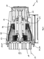
- the 1 shows a vacuum pump designed as a scroll pump 10 .
- This comprises a first housing element 12 and a second housing element 14 connected thereto via screws 15, the second housing element 14 having a pump-active structure, namely a stationary spiral wall 16.
- the second housing element 14 thus forms a stationary spiral component of the scroll vacuum pump 10.
- the spiral wall 16 acts together with a spiral wall 18 which is formed on a movable support plate 20 and together with this forms the orbiter 21 of the scroll vacuum pump 10, which is eccentrically driven via an eccentric shaft 22 to generate a pumping effect.
- a process gas to be pumped is conveyed from an inlet 24, which is defined in the first housing element 12, to an outlet 26, which is defined in the second housing element 14.
- the outer two turns 19 of the spiral wall 18 are formed by wall sections, each having a constant distance from the center point of the spirals 18 in the circumferential direction. Even if, strictly speaking, these wall sections do not form spiral sections, they are assigned to the spiral 18 in the context of the present invention and referred to as turns 19 of the same. However, the principles of the present invention apply equally to configurations in which the spiral wraps flare out continuously from the midpoint of the spiral toward its free end.
- the eccentric shaft 22 is driven by an electric motor 28 and supported by two roller bearings 30 .
- the eccentric shaft 22 comprises an eccentric pin 32 which is arranged eccentrically to its axis of rotation and which transmits its eccentric deflection to the movable spiral component 20 via a further roller bearing 34 .
- a corrugated bellows 36 On the movable support plate 20, to seal the drive, there is also an in 1 left-side first end of a corrugated bellows 36 is fixed, whose right-side second end is fixed to the housing base of the first housing element 12.
- the first end of the corrugated bellows 36 on the left follows the deflection of the movable carrier plate 20.
- the corrugated bellows 36 surrounding the eccentric shaft 22 is flexible but inherently torsionally rigid and thus prevents, due to the fact that it is attached to the carrier plate 20 on the one hand and to the first housing element on the other 12 is fixed so that the carrier plate 20 or the orbiter 21 can rotate about itself.
- the scroll vacuum pump 10 also includes a fan 38 for generating a cooling air flow 46.
- An air guide hood 40 is provided for this cooling air flow 46, to which the fan 38 is also attached.
- the air guide hood 40 and the housing elements 12 and 14 are shaped such that the cooling air flow 46 substantially flows around the entire pump housing and thus achieves good cooling performance.
- the scroll vacuum pump 10 also includes an electronics housing 42 in which a control device and power electronics components for driving the motor 28 are arranged.
- the electronics housing 42 also forms a base for the pump 10.
- a channel 44 is formed between the electronics housing 42 and the first housing element 12, through which the air flow 46 generated by the fan 38 is guided along the first housing element 12 and also along the electronics housing 42, so that both are effective be cooled.
- the right hand second end of the bellows 36 is secured to the housing base of the first housing member 12 by a plurality of fasteners 50 evenly spaced around the bellows 36, see 3 . Since the subassembly consisting of orbiter 21 and corrugated bellows 36 is preassembled as part of the pump assembly and then inserted as a unit into the first housing element 12, the fastening elements 50 in question must be accessible for an assembly tool in order to be attached to the housing base of the first housing element 12 can.
- a sufficiently large annular gap 23 is formed between the orbiter 21, in particular its support plate 20, and the first housing element 12, a corresponding tool can be inserted through this into the suction area 48 for the fastening means in question (in the 1 not shown) are introduced in order to be able to screw them to the housing base in order to attach the second end of the corrugated bellows 36 .
- the diameter of the support plate 20 to improve the pumping speed of the scroll vacuum pump 10 has a diameter which is so large that the annular gap 23 between the carrier plate 20 and the first housing element 12 is too small for a tool to be able to be inserted through this into the suction region 48 in the manner described above in order to actuate the fastening means 50 .
- the pump 3 the remaining annular gap 50 is covered by a web 52 running around in the circumferential direction, which is formed on the inside of the first housing element 12 .
- a plurality of through openings 54 are formed in the carrier plate 20, through which the suction area 48, which is on the spiral 18 of the Orbiters 21 facing away from the support plate 20 is accessible for a tool for assembly purposes.
- a total of four through-openings 54 are formed in the carrier plate 20, which are arranged distributed uniformly around the center point of the spiral 16 in the circumferential direction.
- an indentation 56 or recess is formed in the peripheral edge of the support plate 20 through which the process gas can be sucked out of the intake area 48 into the orbiter 21 .
- the indentation 56 in question merges into one of the through-openings 54 .
- indentation 56 may also be formed on the peripheral edge of support plate 20 at a point between two through-openings 54 . Since, due to the special shape of the indentation 56, all areas of the intake area 48 are accessible for assembly purposes through the same, the formation of the through-openings 54 of the carrier plate 20 can also be dispensed with under certain circumstances.
- the indentation 56 includes a peripheral portion 64 which is located radially outward of the outermost turn 19 of the scroll 18 and which extends circumferentially with respect to the midpoint of the scroll through an arc angle of about 20°.
- the peripheral section 64 extends in the radial direction inwards to the outermost turn 19 of the spiral 18 , being flanked radially inward by a section of the outermost turn 19 of the spiral 18 . Due to the fact that the peripheral section 64 extends in the peripheral direction over a relatively large arc angle, any sections of the suction area 48 are accessible through this peripheral section 64 for a tool for assembly purposes, which is why the through openings 54 are not absolutely necessary in this case.
- the indentation 56 in the embodiment shown here also includes a radial section 66, into which the peripheral section 64 merges at one end and which extends from the peripheral edge of the carrier plate 20 in the radial direction inwards to above the outermost turn 19 of the spiral 18 extends, for which the outermost turn 19 in the region of the radial section 66 is interrupted.
- each fastening means 50 is assigned a through-opening 54.
- the through openings 54 are aligned with the fastening means 50 assigned to them in such a way that an imaginary straight line 58 (see the 3 ), on which a through opening 54 and the fastening means 50 located closest thereto lie, has no point of intersection with the spiral 18 of the orbiter 21.
- an imaginary straight line 58 see the 3
- a tool can be guided through the through-opening 54 to the fastening means 50 in order to be able to screw them to the housing base of the first housing element 12.
- the through-openings 54 are closed by means of suitable closure elements 60 , which can be, for example, screw elements screwed into the through-openings 54 .
- the first housing element 12 has radial bulges 62 at a point radially outside of the orbiter 21, as shown in FIG 2 are indicated schematically in dashed lines. These bulges 62 also ensure access to the intake area 48 which is located on the side of the support plate 20 facing away from the spiral 18 of the orbiter 21 .
- the first housing element 12 has only three bulges 62 which are spaced apart from one another by an arc angle of 90° in the circumferential direction and are therefore located at the half past five, half past eight or half past eleven o'clock position of the carrier plate 20 are located, since the intake area 48 is accessible in the area of the half past two o'clock position through the indentation 56 provided there on the peripheral edge of the carrier plate 20 .
- the first housing element 12 also have a corresponding bulge 62 at the half past two o'clock position to gain access to the corresponding portions of the intake area 48.
- the number of bulges 62 corresponds to the number of fastening elements 50 for attaching the second end of the corrugated bellows 36 to the housing base; is, however, on the outer peripheral edge of the support plate 20 as shown in FIG 2 formed an indentation 56, it may be sufficient if the number of bulges is 1 less than the number of fasteners 50, since through the indentation 56 on the peripheral edge of the support plate 20 access to that fastener 50 can be obtained, which is through the three Bulges 62 is not accessible.
Landscapes
- Engineering & Computer Science (AREA)
- Mechanical Engineering (AREA)
- General Engineering & Computer Science (AREA)
- Applications Or Details Of Rotary Compressors (AREA)
- Rotary Pumps (AREA)
Abstract
Description
- Die vorliegende Erfindung betrifft eine Scrollpumpe gemäß dem Oberbegriff des Anspruchs 1, wie sie der Art nach im Wesentlichen beispielsweise aus der
EP 3 153 708 B1 oder derEP 3 647 599 B1 bekanntgeworden ist. - Eine Scrollpumpe ist eine gegen Atmosphärendruck verdichtende Verdrängerpumpe, die sich unter anderem als Kompressor einsetzen lässt. Eine Scrollvakuumpumpe kann zur Erzeugung eines Vakuums in einem an den Gaseinlass angeschlossenen Rezipienten verwendet werden.
- Scrollvakuumpumpen werden auch als Spiralvakuumpumpen oder Spiralfördereinrichtungen bezeichnet. Das einer Scrollpumpe zugrundeliegende Pumpprinzip ist aus dem Stand der Technik grundsätzlich bekannt und wird daher nachfolgend nur in aller Kürze erläutert.
- Eine Pumpstufe einer Scrollpumpe weist zwei ineinander verschachtelte bzw. ineinander gesteckte, beispielsweise archimedische Spiralzylinder auf, welche nachfolgend auch lediglich als Spiralen bezeichnet werden. Jeder Spiralzylinder besteht dabei aus zumindest einer äquidistanten Spiralwand mit einer an einer Stirnseite der Spiralwand vorgesehenen Trägerplatte, wobei die äußeren Windungen des Spiralzylinders, beispielsweise die zwei oder drei äußersten Windungen des Spiralzylinders, durch Wandabschnitte gebildet werden können, die vom Mittelpunkt der Spiralen jeweils einen in Umfangsrichtung konstanten Abstand aufweisen. Auch wenn diese Wandabschnitte somit streng genommen keine Spiralabschnitte bilden, werden sie im Kontext der vorliegenden Erfindung der Spirale zugerechnet und als Windungen derselben bezeichnet.
- Die Spiralzylinder sind dabei so ineinandergesteckt, dass die beiden Spiralzylinder abschnittsweise halbmond- bzw. sichelförmige Volumina umschließen. Eine der beiden Spiralen ist dabei unbeweglich bzw. feststehend im Gehäuse der Pumpe angeordnet, wohingegen die andere Spirale mitsamt ihrer Trägerplatte über einen Exzenterantrieb auf einer kreisförmigen Bahn bewegt werden kann, weshalb diese Spirale zusammen mit ihrer Trägerplatte auch als Orbiter bezeichnet wird. Die beweglich Spirale führt somit eine sogenannte zentralsymmetrische Oszillation aus, was auch als "Wobbeln" oder "Orbitieren" bezeichnet wird. Ein zwischen den Spiralzylindern eingeschlossenes halbmondförmiges Volumen wandert während des Orbitierens der beweglichen Spirale innerhalb der Spiralen zunehmend nach innen, wodurch mittels des wandernden Volumens Prozessgas von einem radial außenliegenden Gaseinlass nach radial zu einem in der Spiralmitte befindlichen Gasauslass gefördert wird.
- Der Exzenterantrieb bzw. dessen Exzenterwelle befindet sich in dem Gehäuse der Pumpe auf der der Spirale des Orbiters abgewandten Seite der Trägerplatte und ist von einer verformbaren Hülse, wie beispielsweise einem Wellbalg umgeben, der einerseits zur Abdichtung des Antriebs gegenüber dem Ansaugbereich und andererseits als Drehsicherung für den Orbiter dient, da sich dieser andernfalls ohne eine Drehsicherung um sich selbst drehen könnte. Um diese Drehsicherung zu gewährleisten, ist die Hülse bzw. der Wellbalg an einem ersten Ende mit der Trägerplatte verbunden, wohingegen das dem ersten Ende gegenüberliegende zweite Ende der Hülse bzw. des Wellbalgs mittels mehrerer Befestigungsmittel im Inneren des Gehäuses am Gehäusegrund verschraubt ist.
- Die Baugruppe bestehend aus Orbiter und Wellbalg wird dabei im Rahmen der Pumpenmontage vormontiert, so dass die in Rede stehende Baugruppe anschließend als Einheit in das Pumpengehäuse eingesetzt werden kann, woraufhin das zweite Ende der Hülse bzw. des Wellbalgs am Gehäusegrund mit den in Rede stehenden Befestigungsmitteln verschraubt werden muss.
- Da zwischen dem Orbiter und insbesondere dessen Trägerplatte und dem Gehäuse ein umlaufender Ringspalt ausgebildet ist, kann durch diesen ein entsprechendes Werkzeug in den Ansaugbereich bis hin zu den in Rede stehenden Befestigungsmitteln geführt werden, um diese zur Anbringung des zweiten Endes der Hülse am Gehäusegrund verschrauben zu können.
- Zur Verbesserung des Saugvermögens bestehender Scrollvakuumpumpen ist es jedoch erwünscht, dass der Orbiter und insbesondere dessen Trägerplatte einen möglichst großen Durchmesser aufweist. Dies führt jedoch dazu, dass der Ringspalt zwischen Trägerplatte und Pumpengehäuse zu klein ist/wird, als dass durch diesen hindurch in der zuvor beschriebenen Art und Weise ein Werkzeug in den Ansaugbereich der Pumpe zur Betätigung der Befestigungsmittel eingeführt werden kann.
- Der Erfindung liegt daher die Aufgabe zugrunde, bei einer gattungsgemäßen Scrollpumpe den Zugang zum Ansaugbereich für Montagezwecke zu verbessern.
- Diese Aufgabe wird mit einer Scrollpumpe, insbesondere einer Scrollvakuumpumpe, mit den Merkmalen des Anspruchs 1 und insbesondere dadurch gelöst, dass in der Trägerplatte mehrere Durchgangsöffnungen ausgebildet sind, durch die ein Gehäusebereich, der sich auf einer der Spirale des Orbiters abgewandten Seite der Trägerplatte befindet, für ein Werkzeug zu Montagezwecken zugänglich ist.
- Bei der Dimensionierung des Orbiters muss somit keine Rücksicht darauf genommen werden, dass der Ringspalt zwischen Trägerplatte und Pumpengehäuse groß genug ist, dass durch diesen ein Werkzeug zur Anbringung der Hülse bzw. des Wellbalgs am Gehäusegrund hindurch geführt werden kann. Vielmehr kann die Trägerplatte des Orbiters zugunsten der Verbesserung des Saugvermögens so groß dimensioniert werden, dass sie im Rahmen ihrer orbitierenden Bewegung gerade nicht mit der Innenwand des Pumpengehäuses kollidiert, ohne dass hierdurch die Montage der Hülse bzw. des Wellbalgs erschwert wird, da diese in der erfindungsgemäßen Art und Weise durch die speziell in der Trägerplatte ausgebildeten Durchgangsöffnungen erfolgen kann, weshalb diese auch als Montageöffnungen bezeichnet werden können.
- Im Folgenden wird nun auf bevorzugte Ausführungsformen der Erfindung eingegangen. Weitere Ausführungsformen können sich auch aus den abhängigen Ansprüchen, der Figurenbeschreibung sowie den Zeichnungen selbst ergeben.
- So kann es gemäß einer Ausführungsform vorgesehen sein, dass in der Trägerplatte eine erste, eine zweite und zumindest eine dritte Durchgangsöffnung ausgebildet sind, die in Umfangsrichtung gleichmäßig verteilt um den Mittelpunkt der Spirale angeordnet sind. Beispielsweise können sich die Durchgangsöffnungen auf einem zum Mittelpunkt der Spirale konzentrischen Kreis befinden und in Umfangsrichtung gleichmäßig beabstandet voneinander angeordnet sein. Der Abstand von der ersten Durchgangsöffnung zu der zweiten Durchgangsöffnung ist somit gleich groß wie der Abstand von der zweiten Durchgangsöffnung zu der dritten Durchgangsöffnung.
- Auch wenn mehr als drei Durchgangsöffnungen in der Trägerplatte ausgebildet sind, können diese in entsprechender Weise in Umfangsrichtung gleichmäßig voneinander beabstandet sein. Dadurch, dass mehrere Durchgangsöffnungen in der Trägerplatte ausgebildet sind, sind die Befestigungsmittel zur Anbringung des zweiten Endes der Hülse am Gehäusegrund besonders leicht zugänglich. So sind nämlich die Befestigungsmittel um den Umfang der Hülse verteilt angeordnet, so dass von ein und derselben Durchgangsöffnung aus nicht alle Befestigungsmittel mittels eines entsprechenden Werkzeugs zugänglich sind. Dadurch, dass in der erfindungsgemäßen Art und Weise jedoch die Durchgangsöffnungen ebenfalls in Umfangsrichtung beabstandet voneinander angeordnet sind, wird somit ein erleichterter Zugang zu allen Befestigungsmitteln geschaffen.
- Damit ein durch die Durchgangsöffnung hindurchzuführendes Werkzeug an dem Wellbalg, der sich auf der der Spirale des Orbiters abgewandten Seite der Trägerplatte befindet, zu Montagezwecken vorbei geführt werden kann, kann es gemäß einer weiteren Ausführungsform vorgesehen sein, dass die Durchgangsöffnungen in der Trägerplatte zwischen in radialer Richtung aufeinanderfolgende Windungen der Spirale ausgebildet sind, insbesondere zwischen den beiden äußersten Windungen. Unter Umständen kann es sogar sinnvoll sein, die Durchgangsöffnungen radial außerhalb der äußersten Windung der Spirale in der Trägerplatte auszubilden.
- Gemäß einer weiteren Ausführungsform kann es insbesondere vorgesehen sein, dass die Anzahl der Befestigungsmittel der Anzahl der Durchgangsöffnungen in der Trägerplatte entspricht. Jedem Befestigungsmittel ist somit gewissermaßen eine damit ausgerichtete Durchgangsöffnung zugeordnet, so dass jedes Befestigungsmittel mittels eines Werkzeugs leicht zugänglich und betätigt werden kann, ohne dass die Gefahr besteht, dass das Werkzeug von dem Befestigungsmittel aufgrund einer unerwünschten Schräg- bzw. Schiefstellung des Werkzeugs abrutscht.
- Wie zuvor erläutert wurde, werden die Durchgangsöffnungen in der Trägerplatte in der erfindungsgemäßen Art und Weise vorgesehen, da bei entsprechend großer Dimensionierung des Orbiters bzw. dessen Trägerplatte der Ringspalt zwischen Trägerplatte und Pumpengehäuse zu klein ist, um ein Werkzeug durch den Ringspalt hindurch in den Ansaugbereich der Pumpe einführen zu können. Die Reduzierung der Größe des Ringspalts hat jedoch gleichermaßen zur Folge, dass das Prozessgas aus dem Ansaugbereich nicht mehr vollkommen ungehindert an der Trägerplatte vorbei in die Pumpstufe strömen kann.
- Dementsprechend kann es gemäß einer weiteren Ausführungsform vorgesehen sein, dass im Umfangsrand der Trägerplatte eine Einbuchtung bzw. eine Aussparung ausgebildet ist, durch die das Prozessgas aus dem Ansaugbereich in axialer Richtung direkt in die Pumpstufe gesaugt werden kann. Gemäß einer bevorzugten Ausführungsform kann es dabei insbesondere vorgesehen sein, dass die in Rede stehende Einbuchtung in eine der Durchgangsöffnungen übergeht. Die betroffene Durchgangsöffnung geht somit in radialer Richtung in die Einbuchtung über, so dass gewissermaßen eine besonders große Montageöffnung entsteht, durch welche hindurch auch schwer zugängliche Bereiche im Ansaugbereich zu Wartungs- oder Montagezwecken zugänglich sind.
- Da das Montagewerkzeug durch die Spirale des Orbiters in die Durchgangsöffnung eingeführt werden muss, ist die maximal mögliche Schrägstellung des Werkzeugs durch die Wandhöhe der Spirale begrenzt. Damit dennoch die Befestigungsmittel durch die Durchgangsöffnungen in der gewünschten Weise zu Montagezwecken zugänglich sind, kann es gemäß einer weiteren Ausführungsform vorgesehen sein, dass jede der Durchgangsöffnungen an einer jeweiligen Stelle der Trägerplatte ausgebildet ist, die derart gewählt ist, dass eine gedachte Gerade, auf der eine Durchgangsöffnung und das dieser Durchgangsöffnung am nächsten gelegene Befestigungsmittel liegen, keinen Schnittpunkt mit der Spirale des Orbiters aufweist. Zu Betätigungszwecken der Befestigungsmittel kann somit ein Werkzeug durch die Durchgangsöffnungen hindurchgeführt werden, ohne dabei mit der Spirale des Orbiters zu kollidieren.
- Da das durch den Orbiter hindurch transportierte Prozessgas die Tendenz aufweist, in den Ansaugbereich zurückzuströmen, und zwar insbesondere durch die in der Trägerplatte ausgebildeten Durchgangsöffnungen, kann es gemäß einer weiteren Ausführungsform vorgesehen sein, dass jede Durchgangsöffnung, außer gegebenenfalls jener, in die gegebenenfalls die zuvor erwähnte Einbuchtung übergeht, ein die jeweilige Durchgangsöffnung abdichtendes Verschlusselement wie beispielsweise eine Schraube aufnimmt. Die Verschlusselemente können beispielsweise in die jeweiligen Durchgangsöffnungen eingeschraubt sein, um diese abzudichten, so dass durch die Pumpstufe bereits verdichtetes Prozessgas durch die Durchgangsöffnungen nicht zurück in den Ansaugbereich der Pumpe strömen kann.
- Gemäß einer weiteren Ausführungsform kann es zusätzlich oder alternativ zu der Ausgestaltung der Trägerplatte mit zumindest einer Durchgangsöffnung vorgesehen sein, dass das Gehäuse an einer Stelle radial außerhalb des Orbiters zumindest drei radiale Ausbuchtungen aufweist, durch die der Gehäusebereich, der sich auf der der Spirale des Orbiters abgewandten Seite der Trägerplatte befindet, für ein Werkzeug zu Montagezwecken zugänglich ist. Beispielsweise kann das Gehäuse in einer Radialebene, in der sich die Trägerplatte des Orbiters befindet, eine rechteckige und insbesondere eine quadratische Querschnittsgestalt aufweisen, so dass durch die Ecken des Rechtecks radial außerhalb der Trägerplatte die in Rede stehenden Ausbuchtungen gebildet werden.
- Da auch durch die in Rede stehenden Ausbuchtungen Prozessgas zurück in den Ansaugbereich der Pumpe strömen kann, kann es gemäß einer weiteren Ausführungsform vorgesehen sein, dass in jede Ausbuchtung ein komplementär zu der jeweiligen Ausbuchtung ausgebildeter Verschlusskörper lösbar eingepasst ist.
- Wie die Durchgangsöffnungen der Trägerplatte können auch die Ausbuchtungen gleichmäßig beabstandet voneinander vorgesehen sein, so dass beispielsweise der Abstand von einer ersten Ausbuchtung zu einer zweiten Ausbuchtung gleich groß ist wie der Abstand von der zweiten Ausbuchtung zu einer dritten Ausbuchtung. Somit sind durch die in Rede stehenden Ausbuchtungen sämtliche Bereiche des Ansaugbereichs der Pumpe gleich gut zugänglich.
- Da die Befestigungsmittel zur Anbringung des zweiten Endes der Hülse am Gehäusegrund gleichmäßig beabstandet um die Hülse vorgesehen sind, kann es sich gemäß einer weiteren Ausführungsform anbieten, dass die Anzahl der Ausbuchtungen gleich groß ist, wie die Anzahl der Befestigungsmittel, so dass jedem Befestigungsmittel gewissermaßen eine Ausbuchtung zugeordnet ist, durch welche hindurch das jeweilige Befestigungsmittel mittels eines geeigneten Werkzeugs zu Montagezwecken zugänglich ist.
- Im Falle, dass jedoch die Trägerplatte an ihrem Umfangsrand mit einer Einbuchtung ausgebildet ist, durch die das Einströmen von Prozessgas in den Orbiter erleichtert wird, kann es in diesem Falle ausreichend sein, dass die Anzahl der Ausbuchtungen um eins geringer ist als die Anzahl der Befestigungsmittel, da eines der Befestigungsmittel durch die Einbuchtung der Trägerplatte zugänglich ist.
- Wie bereits zuvor erläutert wurde, kann es sinnvoll sein, die Durchgangsöffnungen radial außerhalb der äußersten Windung der Spirale in der Trägerplatte auszubilden. Wird der Abstand einer Durchgangsöffnung zum Mittelpunkt der Spirale noch weiter vergrößert, so kann in diesem Falle die Durchgangsöffnung sogar in den Umfangsrand der Trägerplatte übergehen. Die Durchgangsöffnung weißt in diesem Falle also keine umlaufende Berandung auf, sondern öffnet sich zum Umfangsrand der Trägerplatte und geht in diesen über. Gemäß einem Aspekt der vorliegenden Erfindung kann es daher zusätzlich oder alternativ zu der Ausgestaltung der Trägerplatte mit mehreren Durchgangsöffnungen in der Trägerplatte vorgesehen sein, dass in dem Umfangsrand eine Einbuchtung ausgebildet ist, die als Montageöffnung genutzt werden kann, durch die der Gehäusebereich, der sich auf einer der Spirale des Orbiters abgewandten Seite der Trägerplatte befindet, für ein Werkzeug zu Montagezwecken zugänglich ist.
- Gemäß einer speziellen Ausführungsform kann es dabei vorgesehen sein, dass die Spirale mehrere in radialer Richtung aufeinanderfolgende Windungen umfasst, wobei die Einbuchtung einen Umfangsabschnitt umfasst, der radial außerhalb der äußersten Windung der Spirale gelegen ist und sich in Umfangsrichtung in Bezug auf den Mittelpunkt der Spirale über einen Bogenwinkel zwischen 10° und 30°, insbesondere zwischen 15° und 25° und vorzugsweise zwischen 18° und 22°, erstreckt. Sofern hier davon die Rede ist, dass der Umfangsabschnitt radial außerhalb der äußersten Windung der Spirale gelegen ist, so bedeutet dies, dass der Umfangsabschnitt auf seiner radial innenliegenden Seite von einem Abschnitt der äußersten Windung der Spirale beflankt wird. Aufgrund der Tatsache, dass sich der Umfangsabschnitt in Umfangsrichtung über einen verhältnismäßig großen Bogenwinkel hinwegerstreckt, sind somit durch diesen Umfangsabschnitt beliebige Abschnitte des Gehäusebereichs, der sich auf einer der Spirale des Orbiters abgewandten Seite der Trägerplatte befindet, für ein Werkzeug zu Montagezwecken zugänglich. Darüber hinaus kann durch den Umfangsabschnitt das Prozessgas aus dem Ansaugbereich in axialer Richtung direkt in die Pumpstufe und somit mit nur geringen Strömungsverlusten gesaugt werden.
- Um sowohl die Zugänglichkeit des Ansaugbereichs als auch den Zutritt von Prozessgas in die Pumpstufe weiter zu verbessern, kann es gemäß einer weiteren Ausführungsform vorgesehen sein, dass die Einbuchtung einen Radialabschnitt umfasst, in den der Umfangsabschnitt an einem Ende übergeht und der sich von dem Umfangsrand der Trägerplatte in radialer Richtung nach innen bis über die äußerste Windung der Spirale erstreckt, was bedeutet, dass die äußerste Windung der Spirale im Bereich des Radialabschnitts durch denselben unterbrochen ist.
- Im Folgenden wird die Erfindung nun rein exemplarisch unter Bezugnahme auf die Zeichnungen beschrieben, in denen:
- Fig. 1
- eine herkömmliche Scrollvakuumpumpe in einer Schnittdarstellung zeigt;
- Fig. 2
- eine Draufsicht auf den Orbiter in einer erfindungsgemäß ausgebildeten Scrollvakuumpumpe zeigt; und
- Fig. 3
- eine Schnittdarstellung des Abschnitts der Scrollvakuumpumpe der
Fig. 3 gemäß der Schnittführung R-R zeigt. - Die
Fig. 1 zeigt eine als Scrollpumpe 10 ausgebildete Vakuumpumpe. Diese umfasst ein erstes Gehäuseelement 12 und ein damit über Schrauben 15 verbundenes zweites Gehäuseelement 14, wobei das zweite Gehäuseelement 14 eine pumpaktive Struktur aufweist, nämlich eine feststehende Spiralwand 16. Das zweite Gehäuseelement 14 bildet also ein feststehendes Spiralbauteil der Scrollvakuumpumpe 10. Die Spiralwand 16 wirkt mit einer Spiralwand 18 zusammen, die an einer beweglichen Trägerplatte 20 ausgebildet ist und zusammen mit dieser den Orbiter 21 der Scrollvakuumpumpe 10 bildet, der zum Erzeugen einer Pumpwirkung über eine Exzenterwelle 22 exzentrisch angetrieben wird. Dabei wird ein zu pumpendes Prozessgas von einem Einlass 24, welcher in dem ersten Gehäuseelement 12 definiert ist, zu einem Auslass 26 gefördert, welcher in dem zweiten Gehäuseelement 14 definiert ist. - Wie insbesondere der
Fig. 2 entnommen werden kann, werden bei der hier dargestellten Ausführungsform die äußeren beiden Windungen 19 der Spiralwand 18 durch Wandabschnitte gebildet, die vom Mittelpunkt der Spiralen 18 jeweils einen in Umfangsrichtung konstanten Abstand aufweisen. Auch wenn diese Wandabschnitte somit streng genommen keine Spiralabschnitte bilden, werden sie im Kontext der vorliegenden Erfindung der Spirale 18 zugerechnet und als Windungen 19 derselben bezeichnet. Die Prinzipien der vorliegenden Erfindung gelten jedoch gleichermaßen für Ausgestaltungen, bei denen sich die Spiralwindungen vom Mittelpunkt der Spirale in Richtung ihres freien Endes kontinuierlich aufweiten. - Die Exzenterwelle 22 wird durch einen Elektromotor 28 angetrieben und durch zwei Wälzlager 30 gelagert. Die Exzenterwelle 22 umfasst einen exzentrisch zu ihrer Rotationsachse angeordneten Exzenterzapfen 32, der über ein weiteres Wälzlager 34 seine exzentrische Auslenkung an das bewegliche Spiralbauteil 20 überträgt.
- An der beweglichen Trägerplatte 20 ist zur Abdichtung des Antriebs außerdem ein in
Fig. 1 linksseitiges erstes Ende eines Wellbalgs 36 befestigt, dessen rechtsseitiges zweites Ende am Gehäusegrund des ersten Gehäuseelement 12 befestigt ist. Das linksseitige erste Ende des Wellbalgs 36 folgt der Auslenkung der beweglichen Trägerplatte 20. Der die Exzenterwelle 22 umgebende Wellbalg 36 ist biegsam, jedoch in sich torsionssteif ausgebildet und verhindert somit aufgrund der Tatsache, dass er einerseits an der Trägerplatte 20 und andererseits an dem ersten Gehäuseelement 12 befestigt ist, dass sich die Trägerplatte 20 bzw. der Orbiter 21 um sich selbst drehen kann. - Die Scrollvakuumpumpe 10 umfasst ferner einen Lüfter 38 zur Erzeugung eines Kühlluftstromes 46. Für diesen Kühlluftstrom 46 ist eine Luftleithaube 40 vorgesehen, an der auch der Lüfter 38 befestigt ist. Die Luftleithaube 40 und die Gehäuseelemente 12 und 14 sind derart geformt, dass der Kühlluftstrom 46 im Wesentlichen das gesamte Pumpengehäuse umströmt und somit eine gute Kühlleistung erreicht.
- Die Scrollvakuumpumpe 10 umfasst ferner ein Elektronikgehäuse 42, in dem eine Steuerungseinrichtung und Leistungselektronikkomponenten zum Antrieb des Motors 28 angeordnet sind. Das Elektronikgehäuse 42 bildet außerdem einen Standfuß der Pumpe 10. Zwischen dem Elektronikgehäuse 42 und dem ersten Gehäuseelement 12 ist ein Kanal 44 ausgebildet, durch den der vom Lüfter 38 erzeugte Luftstrom 46 am ersten Gehäuseelement 12 und auch am Elektronikgehäuse 42 entlanggeführt wird, sodass beide wirksam gekühlt werden.
- Wie bereits zuvor erwähnt wurde, ist das rechtsseitige zweite Ende des Wellbalgs 36 am Gehäusegrund des ersten Gehäuseelements 12 befestigt, und zwar mittels mehrerer Befestigungselemente 50, welche gleichmäßig beabstandet um den Wellbalg 36 herum angeordnet sind, siehe
Fig. 3 . Da die Baugruppe bestehend aus Orbiter 21 und Wellbalg 36 im Rahmen der Pumpenmontage vormontiert und anschließend als Einheit in das erste Gehäuseelement 12 eingesetzt wird, müssen die in Rede stehenden Befestigungselemente 50 für ein Montagewerkzeug zugänglich sein, um am Gehäusegrund des ersten Gehäuseelements 12 angebracht werden zu können. Da bei der in derFig. 1 dargestellten Scrollvakuumpumpe 10 zwischen dem Orbiter 21, insbesondere dessen Trägerplatte 20, und dem ersten Gehäuseelement 12 ein hinreichend großer Ringspalt 23 ausgebildet ist, kann durch diesen ein entsprechendes Werkzeug in den Ansaugbereich 48 zu den in Rede stehenden Befestigungsmitteln (in derFig. 1 nicht dargestellt) eingeführt werden, um diese zur Anbringung des zweiten Endes des Wellbalgs 36 am Gehäusegrund verschrauben zu können. - Bei der in der
Fig. 3 dargestellten Scrollvakuumpumpe 10 weist jedoch der Durchmesser der Trägerplatte 20 zur Verbesserung des Saugvermögens der Scrollvakuumpumpe 10 einen Durchmesser auf, der so groß ist, dass der Ringspalt 23 zwischen der Trägerplatte 20 und dem ersten Gehäuseelement 12 zu gering ist, als dass durch diesen hindurch in der zuvor beschriebenen Art und Weise ein Werkzeug in den Ansaugbereich 48 zur Betätigung der Befestigungsmittel 50 eingeführt werden könnte. Ferner kommt hinzu, dass bei der Pumpe derFig. 3 der verbleibende Ringspalt 50 durch einen in Umfangsrichtung umlaufenden Steg 52 überdeckt ist, welcher an der Innenseite des ersten Gehäuseelements 12 ausgebildet ist. - Um daher dennoch Zugang zu dem Ansaugbereich 48 und insbesondere zu den Befestigungsmitteln 50 zu Montagezwecken zu haben, ist es erfindungsgemäß daher vorgesehen, dass in der Trägerplatte 20 mehrere Durchgangsöffnungen 54 ausgebildet sind, durch die der Ansaugbereich 48, der sich auf der der Spirale 18 des Orbiters 21 abgewandten Seite der Trägerplatte 20 befindet, für ein Werkzeug zu Montagezwecken zugänglich ist.
- Wie insbesondere der
Fig. 1 entnommen werden kann, sind bei der dort dargestellten Ausführungsform in der Trägerplatte 20 insgesamt vier Durchgangsöffnungen 54 ausgebildet, welche in Umfangsrichtung gleichmäßig verteilt um den Mittelpunkt der Spirale 16 angeordnet sind. Sofern hier davon die Rede ist, dass die Durchgangsöffnungen 54 in Umfangsrichtung gleichmäßig verteilt um den Mittelpunkt der Spirale 16 angeordnet sind, so bedeutet dies, dass die Durchgangsöffnungen 54 in Bezug auf den Mittelpunkt der Spirale 16 jeweils um dasselbe Bogenmaß bzw. um denselben Bogenwinkel α voneinander beabstandet sind, für welchen bei einer Anzahl von n Durchgangsöffnungen gilt: α = 360° / n. - Wie der
Fig. 1 des Weiteren entnommen werden kann, ist in dem Umfangsrand der Trägerplatte 20 eine Einbuchtung 56 bzw. Aussparung ausgebildet, durch die das Prozessgas aus dem Ansaugbereich 48 in den Orbiter 21 gesaugt werden kann. Bei der hier dargestellten Ausführungsform geht die in Rede stehende Einbuchtung 56 in eine der Durchgangsöffnungen 54 über. Alternativ hierzu kann die Einbuchtung 56 jedoch auch am Umfangsrand der Trägerplatte 20 an einer Stelle zwischen zwei Durchgangsöffnungen 54 ausgebildet sein. Da aufgrund der speziellen Gestalt der Einbuchtung 56 durch dieselbe sämtliche Bereiche des Ansaugbereich 48 zu Montagezwecken zugänglich sind, kann auf die Ausbildung der Durchgangsöffnungen 54 Trägerplatte 20 unter Umständen auch verzichtet werden. - Wie der
Fig. 2 entnommen werden kann, umfasst die Einbuchtung 56 einen Umfangsabschnitt 64, der radial außerhalb der äußersten Windung 19 der Spirale 18 gelegen ist und der sich in Umfangsrichtung in Bezug auf den Mittelpunkt der Spirale über einen Bogenwinkel von etwa 20° erstreckt. Der Umfangsabschnitt 64 erstreckt sich dabei in radialer Richtung nach innen bis zu der äußersten Windung 19 der Spirale 18 wobei er radial innerhalb von einem Anschnitt der äußersten Windung 19 der Spirale 18 beflankt wird. Aufgrund der Tatsache, dass sich der Umfangsabschnitt 64 in Umfangsrichtung über einen verhältnismäßig großen Bogenwinkel hinwegerstreckt, sind somit durch diesen Umfangsabschnitt 64 beliebige Abschnitte des Ansaugbereichs 48 für ein Werkzeug zu Montagezwecken zugänglich, weshalb in diesem Falle die Durchgangsöffnungen 54 nicht unbedingt benötigt werden. - Um die Zugänglichkeit des Ansaugbereichs 48 weiter zu verbessern, umfasst die Einbuchtung 56 bei der hier dargestellten Ausführungsform ferner einen Radialabschnitt 66, in den der Umfangsabschnitt 64 an einem Ende übergeht und der sich von dem Umfangsrand der Trägerplatte 20 in radialer Richtung nach innen bis über die äußerste Windung 19 der Spirale 18 erstreckt, wofür die äußerste Windung 19 im Bereich des Radialabschnitts 66 unterbrochen ist.
- Da die Befestigungsmittel 50 zur Anbringung des zweiten Endes des Wellbalgs 36 um den Umfang des Wellbalgs 36 verteilt angeordnet sind, entspricht die Anzahl der Durchgangsöffnungen 54 der Anzahl der Befestigungsmittel 50. Somit ist gewissermaßen jedem Befestigungsmittel 50 eine Durchgangsöffnung 54 zugeordnet. Insbesondere sind die Durchgangsöffnungen 54 dabei derart mit den ihnen jeweils zugeordneten Befestigungsmitteln 50 ausgerichtet, dass eine gedachte Gerade 58 (siehe hierzu die
Fig. 3 ), auf der eine Durchgangsöffnung 54 und das derselben am nächsten gelegene Befestigungsmittel 50 liegen, keinen Schnittpunkt mit der Spirale 18 des Orbiters 21 aufweist. Somit kann entlang der in derFig. 3 eingezeichneten Geraden 58 ein Werkzeug durch die Durchgangsöffnung 54 bis zu den Befestigungsmitteln 50 geführt werden, um diese am Gehäusegrund des ersten Gehäuseelements 12 verschrauben zu können. - Damit durch die Durchgangsöffnungen 54 das Prozessgas nicht zurück in den Ansaugbereich 48 strömen kann, sind die Durchgangsöffnungen 54 mittels geeigneter Verschlusselemente 60 verschlossen, bei denen es sich beispielsweise um in die Durchgangsöffnungen 54 eingeschraubte Schraubelemente handeln kann.
- Zusätzlich oder alternativ zu den Durchgangsöffnungen 54 kann es vorgesehen sein, dass das erste Gehäuseelement 12 an einer Stelle radial außerhalb des Orbiters 21 radiale Ausbuchtungen 62 aufweist, wie sie in der
Fig. 2 schematisch in gestrichelten Linien angedeutet sind. Durch diese Ausbuchtungen 62 wird ebenfalls der Zugang zu dem Ansaugbereich 48 sichergestellt, der sich auf der der Spirale 18 des Orbiters 21 abgewandten Seite der Trägerplatte 20 befindet. - Zwar weist bei der hier dargestellten Ausführungsform das erste Gehäuseelement 12 nur drei Ausbuchtungen 62 auf, die um einen Bogenwinkel von 90° in Umfangsrichtung voneinander beabstandet sind und sich somit an der halb 5-, halb 8- oder halb 11-Uhr-Stellung der Trägerplatte 20 befinden, da der Ansaugbereich 48 im Bereich der halb 2-Uhr-Stellung durch die dort vorgesehene Einbuchtung 56 am Umfangsrand der Trägerplatte 20 zugänglich ist. Sollte solch eine Einbuchtung jedoch nicht oder an einer anderen Stelle vorgesehen sein, kann das erste Gehäuseelement 12 auch an der halb 2-Uhr-Stellung eine entsprechende Ausbuchtung 62 aufweisen, um Zugang zu den entsprechenden Bereichen des Ansaugbereichs 48 zu erhalten.
- Grundsätzlich entspricht die Anzahl der Ausbuchtungen 62 der Anzahl der Befestigungselemente 50 zur Anbringung des zweiten Endes des Wellbalgs 36 am Gehäusegrund; ist jedoch am Außenumfangsrand der Trägerplatte 20 gemäß der Darstellung der
Fig. 2 eine Einbuchtung 56 ausgebildet, so kann es ausreichend sein, wenn die Anzahl der Ausbuchtungen um 1 geringer ist als die Anzahl der Befestigungsmittel 50, da durch die Einbuchtung 56 am Umfangsrand der Trägerplatte 20 Zugang zu jenem Befestigungsmittel 50 erlangt werden kann, das durch die drei Ausbuchtungen 62 nicht zugänglich ist. -
- 10
- Scrollvakuumpumpe
- 12
- erstes Gehäuseelement
- 14
- zweites Gehäuseelement
- 15
- Schrauben
- 16
- Spiralwand/Spirale
- 18
- Spiralwand/Spirale
- 19
- Windungen
- 20
- Trägerplatte
- 21
- Orbiter
- 22
- Exzenterwelle
- 23
- Ringspalt
- 24
- Einlass
- 26
- Auslass
- 28
- Motor
- 30
- Wälzlager
- 32
- Exzenterzapfen
- 34
- Wälzlager
- 36
- Wellbalg
- 38
- Lüfter
- 40
- Luftleithaube
- 42
- Elektronikgehäuse
- 44
- Kanal
- 46
- Luftstrom
- 48
- Ansaugbereich
- 50
- Befestigungselement
- 52
- Steg
- 54
- Durchgangsöffnung
- 56
- Einbuchtung
- 58
- Gerade
- 60
- Verschlusselement
- 62
- Ausbuchtung
- 64
- Umfangsabschnitt
- 66
- Radialabschnitt
Claims (15)
- Scrollpumpe, insbesondere Scrollvakuumpumpe (10), mit einem Gehäuse (12, 14) und einem in dem Gehäuse (12) befindlichen Orbiter (21), der eine Trägerplatte (20) und eine sich von der Trägerplatte (20) erstreckende Spirale (18) aufweist,
dadurch gekennzeichnet , dass
in der Trägerplatte (20) mehrere Durchgangsöffnungen (54) ausgebildet sind, durch die ein Gehäusebereich (48), der sich auf einer der Spirale (18) des Orbiters (21) abgewandten Seite der Trägerplatte (20) befindet, für ein Werkzeug zu Montagezwecken zugänglich ist. - Scrollpumpe nach Anspruch 1,
dadurch gekennzeichnet , dass
in der Trägerplatte (20) eine erste, eine zweite und zumindest eine dritte Durchgangsöffnung (54) ausgebildet sind, die in Umfangsrichtung gleichmäßig verteilt um den Mittelpunkt der Spirale (18) angeordnet sind. - Scrollpumpe nach Anspruch 1 oder 2,
dadurch gekennzeichnet , dass
die Spirale mehrere Windungen umfasst, wobei die Durchgangsöffnungen (54) in der Trägerplatte (20) zwischen in radialer Richtung aufeinanderfolgende Windungen ausgebildet sind, insbesondere zwischen den beiden äußersten Windungen. - Scrollpumpe nach zumindest einem der vorstehenden Ansprüche,
dadurch gekennzeichnet , dass
die Trägerplatte (20) einen Umfangsrand aufweist, wobei in dem Umfangsrand eine Einbuchtung (56) ausgebildet ist. - Scrollpumpe nach Anspruch 4,
dadurch gekennzeichnet , dass
die Einbuchtung (56) in eine der Durchgangsöffnungen (54) übergeht. - Scrollpumpe nach zumindest einem der vorstehenden Ansprüche,
dadurch gekennzeichnet , dass
die Scrollpumpe innerhalb des Gehäuses (12) auf der der Spirale (18) des Orbiters (21) abgewandten Seite der Trägerplatte (20) ferner eine antriebswirksam mit der Trägerplatte (20) verbundene Exzenterwelle (22) sowie eine verformbare Hülse, insbesondere in Form eines Wellbalgs (36), umfasst, die/der die Exzenterwelle (22) umgibt und an einem ersten Ende mit der Trägerplatte (20) verbunden ist, wobei die Hülse an einem dem ersten Ende gegenüberliegenden zweiten Ende mittels mehrerer in Umfangsrichtung gleichmäßig voneinander beabstandeter Befestigungsmittel (50) an dem Gehäuse (12) angebracht ist, deren Anzahl der Anzahl der Durchgangsöffnungen (54) entspricht. - Scrollpumpe nach Anspruch 6,
dadurch gekennzeichnet , dass
jede der Durchgangsöffnungen (54) an einer jeweiligen Stelle der Trägerplatte (20) ausgebildet ist, die derart gewählt ist, dass eine Gerade (58), auf der eine Durchgangsöffnung (54) und das dieser Durchgangsöffnung (54) am nächsten gelegene Befestigungsmittel (50) liegen, keinen Schnittpunkt mit der Spirale (18) des Orbiters (21) aufweist. - Scrollpumpe nach zumindest einem der vorstehenden Ansprüche,
dadurch gekennzeichnet , dass
jede Durchgangsöffnung (54) ein die jeweilige Durchgangsöffnung (54) abdichtendes Verschlusselement (60) lösbar aufnimmt, insbesondere ein Schraubelement, das in die Durchgangsöffnung (54) eingeschraubt ist. - Scrollpumpe nach zumindest einem der vorstehenden Ansprüche,
dadurch gekennzeichnet , dass
es zusätzlich oder alternativ zu der Ausgestaltung der Trägerplatte (20) mit zumindest einer Durchgangsöffnung (54) vorgesehen ist, dass das Gehäuse (12) an einer Stelle radial außerhalb des Orbiters (21) zumindest drei Ausbuchtungen (62) aufweist, durch die der Gehäusebereich (48), der sich auf der der Spirale (18) des Orbiters (21) abgewandten Seite der Trägerplatte (20) befindet, für ein Werkzeug zu Montagezwecken zugänglich ist. - Scrollpumpe nach Anspruch 9,
dadurch gekennzeichnet , dass
der Abstand von einer ersten Ausbuchtung (62) zu einer zweiten Ausbuchtung (62) gleich groß ist wie der Abstand von der zweiten Ausbuchtung (62) zu einer dritten Ausbuchtung (62). - Scrollpumpe nach Anspruch 9 oder 10,
dadurch gekennzeichnet , dass
die Scrollpumpe innerhalb des Gehäuses (12) auf der der Spirale (18) des Orbiters (21) abgewandten Seite der Trägerplatte (20) ferner eine antriebswirksam mit der Trägerplatte (20) verbundene Exzenterwelle (22) sowie eine verformbare Hülse, insbesondere in Form eines Wellbalgs (36), umfasst, die/der die Exzenterwelle (22) umgibt und an einem ersten Ende mit der Trägerplatte (20) verbunden ist, wobei die Hülse an einem dem ersten Ende gegenüberliegenden zweiten Ende mittels mehrerer in Umfangsrichtung gleichmäßig voneinander beabstandeter Befestigungsmittel (50) an dem Gehäuse (12) angebracht ist, deren Anzahl gleich groß oder um eins höher ist als die Anzahl der Ausbuchtungen (62). - Scrollpumpe nach zumindest einem der Ansprüche 9 bis 11,
dadurch gekennzeichnet , dass
in jede Ausbuchtung (62) ein komplementär zu der jeweiligen Ausbuchtung (62) ausgebildeter Verschlusskörper lösbar eingepasst ist. - Scrollpumpe, insbesondere Scrollvakuumpumpe (10), mit einem Gehäuse (12, 14) und einem in dem Gehäuse (12) befindlichen Orbiter (21), der eine Trägerplatte (20) und eine sich von der Trägerplatte (20) erstreckende Spirale (18) aufweist,
dadurch gekennzeichnet , dass
die Trägerplatte (20) einen Umfangsrand aufweist, wobei in dem Umfangsrand eine Einbuchtung (56) ausgebildet ist, durch die ein Gehäusebereich (48), der sich auf einer der Spirale (18) des Orbiters (21) abgewandten Seite der Trägerplatte (20) befindet, für ein Werkzeug zu Montagezwecken zugänglich ist. - Scrollpumpe nach Anspruch 13,
dadurch gekennzeichnet , dass
die Spirale (18) mehrere Windungen (19) umfasst, wobei die Einbuchtung (56) einen Umfangsabschnitt (64) umfasst, der radial außerhalb der äußersten Windung (19) der Spirale (18) gelegen ist und sich in Umfangsrichtung in Bezug auf den Mittelpunkt der Spirale (18) über einen Bogenwinkel zwischen 10° und 30°, insbesondere zwischen 15° und 25° und vorzugsweise zwischen 18° und 22°, erstreckt. - Scrollpumpe nach Anspruch 14,
dadurch gekennzeichnet , dass
die Einbuchtung (56) einen Radialabschnitt (66) umfasst, der sich vom Umfangsrand der Trägerplatte (20) in radialer Richtung nach innen bis über die äußerste Windung (19) der Spirale (18) erstreckt.
Priority Applications (1)
| Application Number | Priority Date | Filing Date | Title |
|---|---|---|---|
| EP23179555.0A EP4234932B1 (de) | 2023-06-15 | 2023-06-15 | Scrollpumpe mit verbessertem zugang zum ansaugbereich zu montagezwecken |
Applications Claiming Priority (1)
| Application Number | Priority Date | Filing Date | Title |
|---|---|---|---|
| EP23179555.0A EP4234932B1 (de) | 2023-06-15 | 2023-06-15 | Scrollpumpe mit verbessertem zugang zum ansaugbereich zu montagezwecken |
Publications (3)
| Publication Number | Publication Date |
|---|---|
| EP4234932A2 true EP4234932A2 (de) | 2023-08-30 |
| EP4234932A3 EP4234932A3 (de) | 2024-01-17 |
| EP4234932B1 EP4234932B1 (de) | 2025-04-09 |
Family
ID=86851397
Family Applications (1)
| Application Number | Title | Priority Date | Filing Date |
|---|---|---|---|
| EP23179555.0A Active EP4234932B1 (de) | 2023-06-15 | 2023-06-15 | Scrollpumpe mit verbessertem zugang zum ansaugbereich zu montagezwecken |
Country Status (1)
| Country | Link |
|---|---|
| EP (1) | EP4234932B1 (de) |
Citations (2)
| Publication number | Priority date | Publication date | Assignee | Title |
|---|---|---|---|---|
| EP3153708B1 (de) | 2015-10-06 | 2019-07-17 | Pfeiffer Vacuum Gmbh | Scrollpumpe und verfahren zum betreiben einer scrollpumpe |
| EP3647599B1 (de) | 2019-10-07 | 2021-12-22 | Pfeiffer Vacuum Gmbh | Vakuumpumpe, scrollpumpe und herstellungsverfahren für solche |
Family Cites Families (4)
| Publication number | Priority date | Publication date | Assignee | Title |
|---|---|---|---|---|
| JPS5915691A (ja) * | 1982-07-15 | 1984-01-26 | Sanden Corp | スクロ−ル型流体装置 |
| US6123517A (en) * | 1997-11-24 | 2000-09-26 | Copeland Corporation | Scroll machine with capacity modulation |
| JP2001304142A (ja) * | 2000-04-25 | 2001-10-31 | Yamaha Motor Co Ltd | スクロールコンプレッサ |
| US10221852B2 (en) * | 2006-02-14 | 2019-03-05 | Air Squared, Inc. | Multi stage scroll vacuum pumps and related scroll devices |
-
2023
- 2023-06-15 EP EP23179555.0A patent/EP4234932B1/de active Active
Patent Citations (2)
| Publication number | Priority date | Publication date | Assignee | Title |
|---|---|---|---|---|
| EP3153708B1 (de) | 2015-10-06 | 2019-07-17 | Pfeiffer Vacuum Gmbh | Scrollpumpe und verfahren zum betreiben einer scrollpumpe |
| EP3647599B1 (de) | 2019-10-07 | 2021-12-22 | Pfeiffer Vacuum Gmbh | Vakuumpumpe, scrollpumpe und herstellungsverfahren für solche |
Also Published As
| Publication number | Publication date |
|---|---|
| EP4234932A3 (de) | 2024-01-17 |
| EP4234932B1 (de) | 2025-04-09 |
Similar Documents
| Publication | Publication Date | Title |
|---|---|---|
| DE69114245T2 (de) | Spiralverdichter. | |
| DE69106471T2 (de) | Gegengewichtschild für Kühlverdichter. | |
| DE3327453C2 (de) | ||
| DE19952296C2 (de) | Spiralmaschine, insbesondere Spiralverdichter | |
| DE19959417C2 (de) | Spiralkompressor | |
| DE69628439T2 (de) | Drehkolbenverdichter | |
| EP0392975A1 (de) | Rotierender Spirallader für kompressible Medien | |
| EP4253720B1 (de) | Scrollvakuumpumpe und scrollvakuumpumpen-system | |
| DE69503862T2 (de) | Pumpe mit doppelzylindrischen rotoren | |
| EP2382393A1 (de) | Seitenkanalgebläse, insbesondere sekundärluftgebläse für eine verbrennungskraftmaschine | |
| EP4198261A1 (de) | Schraubenspindelpumpe | |
| EP4198309A1 (de) | Schraubenspindelpumpe | |
| EP0363503B1 (de) | Pumpenstufe für eine Hochvakuumpumpe | |
| EP3667086B1 (de) | Verdrängermaschine nach dem spiralprinzip, insbesondere scrollverdichter für eine fahrzeugklimaanlage | |
| DE3722164A1 (de) | Turbomolekularpumpe | |
| DE69111737T2 (de) | Spiralverdichter. | |
| DE102006058980A1 (de) | Flügelzellenpumpe | |
| EP4234932B1 (de) | Scrollpumpe mit verbessertem zugang zum ansaugbereich zu montagezwecken | |
| DE3926152C2 (de) | ||
| EP2342464B1 (de) | Seitenkanalgebläse, insbesondere sekundärluftgebläse für eine verbrennungskraftmaschine | |
| DE2852852B1 (de) | Kolbenpumpe,insbesondere Radialkolbenpumpe | |
| DE2902301C2 (de) | Flügelzellenpumpe | |
| DE4338865C2 (de) | Spiralverdichter mit Gegengewicht | |
| DE102005047175A1 (de) | Flügelzellenpumpe | |
| EP2342465B1 (de) | Seitenkanalgebläse, insbesondere sekundärluftgebläse für eine verbrennungskraftmaschine |
Legal Events
| Date | Code | Title | Description |
|---|---|---|---|
| PUAI | Public reference made under article 153(3) epc to a published international application that has entered the european phase |
Free format text: ORIGINAL CODE: 0009012 |
|
| STAA | Information on the status of an ep patent application or granted ep patent |
Free format text: STATUS: THE APPLICATION HAS BEEN PUBLISHED |
|
| AK | Designated contracting states |
Kind code of ref document: A2 Designated state(s): AL AT BE BG CH CY CZ DE DK EE ES FI FR GB GR HR HU IE IS IT LI LT LU LV MC ME MK MT NL NO PL PT RO RS SE SI SK SM TR |
|
| PUAL | Search report despatched |
Free format text: ORIGINAL CODE: 0009013 |
|
| AK | Designated contracting states |
Kind code of ref document: A3 Designated state(s): AL AT BE BG CH CY CZ DE DK EE ES FI FR GB GR HR HU IE IS IT LI LT LU LV MC ME MK MT NL NO PL PT RO RS SE SI SK SM TR |
|
| RIC1 | Information provided on ipc code assigned before grant |
Ipc: F04C 29/00 20060101ALI20231208BHEP Ipc: F04C 25/02 20060101ALI20231208BHEP Ipc: F04C 23/00 20060101ALI20231208BHEP Ipc: F04C 18/02 20060101AFI20231208BHEP |
|
| STAA | Information on the status of an ep patent application or granted ep patent |
Free format text: STATUS: REQUEST FOR EXAMINATION WAS MADE |
|
| 17P | Request for examination filed |
Effective date: 20240116 |
|
| RBV | Designated contracting states (corrected) |
Designated state(s): AL AT BE BG CH CY CZ DE DK EE ES FI FR GB GR HR HU IE IS IT LI LT LU LV MC ME MK MT NL NO PL PT RO RS SE SI SK SM TR |
|
| GRAP | Despatch of communication of intention to grant a patent |
Free format text: ORIGINAL CODE: EPIDOSNIGR1 |
|
| STAA | Information on the status of an ep patent application or granted ep patent |
Free format text: STATUS: GRANT OF PATENT IS INTENDED |
|
| INTG | Intention to grant announced |
Effective date: 20250114 |
|
| GRAS | Grant fee paid |
Free format text: ORIGINAL CODE: EPIDOSNIGR3 |
|
| GRAA | (expected) grant |
Free format text: ORIGINAL CODE: 0009210 |
|
| STAA | Information on the status of an ep patent application or granted ep patent |
Free format text: STATUS: THE PATENT HAS BEEN GRANTED |
|
| AK | Designated contracting states |
Kind code of ref document: B1 Designated state(s): AL AT BE BG CH CY CZ DE DK EE ES FI FR GB GR HR HU IE IS IT LI LT LU LV MC ME MK MT NL NO PL PT RO RS SE SI SK SM TR |
|
| REG | Reference to a national code |
Ref country code: GB Ref legal event code: FG4D Free format text: NOT ENGLISH |
|
| REG | Reference to a national code |
Ref country code: CH Ref legal event code: EP |
|
| REG | Reference to a national code |
Ref country code: DE Ref legal event code: R096 Ref document number: 502023000801 Country of ref document: DE |
|
| REG | Reference to a national code |
Ref country code: IE Ref legal event code: FG4D Free format text: LANGUAGE OF EP DOCUMENT: GERMAN |
|
| REG | Reference to a national code |
Ref country code: NL Ref legal event code: MP Effective date: 20250409 |
|
| PG25 | Lapsed in a contracting state [announced via postgrant information from national office to epo] |
Ref country code: NL Free format text: LAPSE BECAUSE OF FAILURE TO SUBMIT A TRANSLATION OF THE DESCRIPTION OR TO PAY THE FEE WITHIN THE PRESCRIBED TIME-LIMIT Effective date: 20250409 |
|
| PG25 | Lapsed in a contracting state [announced via postgrant information from national office to epo] |
Ref country code: FI Free format text: LAPSE BECAUSE OF FAILURE TO SUBMIT A TRANSLATION OF THE DESCRIPTION OR TO PAY THE FEE WITHIN THE PRESCRIBED TIME-LIMIT Effective date: 20250409 Ref country code: ES Free format text: LAPSE BECAUSE OF FAILURE TO SUBMIT A TRANSLATION OF THE DESCRIPTION OR TO PAY THE FEE WITHIN THE PRESCRIBED TIME-LIMIT Effective date: 20250409 Ref country code: PT Free format text: LAPSE BECAUSE OF FAILURE TO SUBMIT A TRANSLATION OF THE DESCRIPTION OR TO PAY THE FEE WITHIN THE PRESCRIBED TIME-LIMIT Effective date: 20250811 |
|
| PGFP | Annual fee paid to national office [announced via postgrant information from national office to epo] |
Ref country code: DE Payment date: 20250827 Year of fee payment: 3 |
|
| REG | Reference to a national code |
Ref country code: LT Ref legal event code: MG9D |
|
| PG25 | Lapsed in a contracting state [announced via postgrant information from national office to epo] |
Ref country code: GR Free format text: LAPSE BECAUSE OF FAILURE TO SUBMIT A TRANSLATION OF THE DESCRIPTION OR TO PAY THE FEE WITHIN THE PRESCRIBED TIME-LIMIT Effective date: 20250710 Ref country code: NO Free format text: LAPSE BECAUSE OF FAILURE TO SUBMIT A TRANSLATION OF THE DESCRIPTION OR TO PAY THE FEE WITHIN THE PRESCRIBED TIME-LIMIT Effective date: 20250709 |
|
| PG25 | Lapsed in a contracting state [announced via postgrant information from national office to epo] |
Ref country code: PL Free format text: LAPSE BECAUSE OF FAILURE TO SUBMIT A TRANSLATION OF THE DESCRIPTION OR TO PAY THE FEE WITHIN THE PRESCRIBED TIME-LIMIT Effective date: 20250409 |
|
| PGFP | Annual fee paid to national office [announced via postgrant information from national office to epo] |
Ref country code: IT Payment date: 20250630 Year of fee payment: 3 |
|
| PG25 | Lapsed in a contracting state [announced via postgrant information from national office to epo] |
Ref country code: BG Free format text: LAPSE BECAUSE OF FAILURE TO SUBMIT A TRANSLATION OF THE DESCRIPTION OR TO PAY THE FEE WITHIN THE PRESCRIBED TIME-LIMIT Effective date: 20250409 |
|
| PG25 | Lapsed in a contracting state [announced via postgrant information from national office to epo] |
Ref country code: HR Free format text: LAPSE BECAUSE OF FAILURE TO SUBMIT A TRANSLATION OF THE DESCRIPTION OR TO PAY THE FEE WITHIN THE PRESCRIBED TIME-LIMIT Effective date: 20250409 |
|
| PG25 | Lapsed in a contracting state [announced via postgrant information from national office to epo] |
Ref country code: RS Free format text: LAPSE BECAUSE OF FAILURE TO SUBMIT A TRANSLATION OF THE DESCRIPTION OR TO PAY THE FEE WITHIN THE PRESCRIBED TIME-LIMIT Effective date: 20250709 |
|
| PG25 | Lapsed in a contracting state [announced via postgrant information from national office to epo] |
Ref country code: IS Free format text: LAPSE BECAUSE OF FAILURE TO SUBMIT A TRANSLATION OF THE DESCRIPTION OR TO PAY THE FEE WITHIN THE PRESCRIBED TIME-LIMIT Effective date: 20250809 |
|
| PG25 | Lapsed in a contracting state [announced via postgrant information from national office to epo] |
Ref country code: LV Free format text: LAPSE BECAUSE OF FAILURE TO SUBMIT A TRANSLATION OF THE DESCRIPTION OR TO PAY THE FEE WITHIN THE PRESCRIBED TIME-LIMIT Effective date: 20250409 |
|
| REG | Reference to a national code |
Ref country code: DE Ref legal event code: R097 Ref document number: 502023000801 Country of ref document: DE |
|
| PG25 | Lapsed in a contracting state [announced via postgrant information from national office to epo] |
Ref country code: DK Free format text: LAPSE BECAUSE OF FAILURE TO SUBMIT A TRANSLATION OF THE DESCRIPTION OR TO PAY THE FEE WITHIN THE PRESCRIBED TIME-LIMIT Effective date: 20250409 Ref country code: SM Free format text: LAPSE BECAUSE OF FAILURE TO SUBMIT A TRANSLATION OF THE DESCRIPTION OR TO PAY THE FEE WITHIN THE PRESCRIBED TIME-LIMIT Effective date: 20250409 |
|
| PG25 | Lapsed in a contracting state [announced via postgrant information from national office to epo] |
Ref country code: EE Free format text: LAPSE BECAUSE OF FAILURE TO SUBMIT A TRANSLATION OF THE DESCRIPTION OR TO PAY THE FEE WITHIN THE PRESCRIBED TIME-LIMIT Effective date: 20250409 |
|
| PG25 | Lapsed in a contracting state [announced via postgrant information from national office to epo] |
Ref country code: SK Free format text: LAPSE BECAUSE OF FAILURE TO SUBMIT A TRANSLATION OF THE DESCRIPTION OR TO PAY THE FEE WITHIN THE PRESCRIBED TIME-LIMIT Effective date: 20250409 |
|
| PG25 | Lapsed in a contracting state [announced via postgrant information from national office to epo] |
Ref country code: MC Free format text: LAPSE BECAUSE OF FAILURE TO SUBMIT A TRANSLATION OF THE DESCRIPTION OR TO PAY THE FEE WITHIN THE PRESCRIBED TIME-LIMIT Effective date: 20250409 |
|
| PLBE | No opposition filed within time limit |
Free format text: ORIGINAL CODE: 0009261 |
|
| STAA | Information on the status of an ep patent application or granted ep patent |
Free format text: STATUS: NO OPPOSITION FILED WITHIN TIME LIMIT |
|
| PG25 | Lapsed in a contracting state [announced via postgrant information from national office to epo] |
Ref country code: LU Free format text: LAPSE BECAUSE OF NON-PAYMENT OF DUE FEES Effective date: 20250615 |
|
| REG | Reference to a national code |
Ref country code: CH Ref legal event code: L10 Free format text: ST27 STATUS EVENT CODE: U-0-0-L10-L00 (AS PROVIDED BY THE NATIONAL OFFICE) Effective date: 20260218 |
|
| REG | Reference to a national code |
Ref country code: BE Ref legal event code: MM Effective date: 20250630 |
|
| PG25 | Lapsed in a contracting state [announced via postgrant information from national office to epo] |
Ref country code: RO Free format text: LAPSE BECAUSE OF FAILURE TO SUBMIT A TRANSLATION OF THE DESCRIPTION OR TO PAY THE FEE WITHIN THE PRESCRIBED TIME-LIMIT Effective date: 20250409 |
|
| 26N | No opposition filed |
Effective date: 20260112 |
|
| PG25 | Lapsed in a contracting state [announced via postgrant information from national office to epo] |
Ref country code: IE Free format text: LAPSE BECAUSE OF NON-PAYMENT OF DUE FEES Effective date: 20250615 |
|
| PG25 | Lapsed in a contracting state [announced via postgrant information from national office to epo] |
Ref country code: BE Free format text: LAPSE BECAUSE OF NON-PAYMENT OF DUE FEES Effective date: 20250630 |
|
| PG25 | Lapsed in a contracting state [announced via postgrant information from national office to epo] |
Ref country code: FR Free format text: LAPSE BECAUSE OF NON-PAYMENT OF DUE FEES Effective date: 20250630 |
|
| PG25 | Lapsed in a contracting state [announced via postgrant information from national office to epo] |
Ref country code: LT Free format text: LAPSE BECAUSE OF FAILURE TO SUBMIT A TRANSLATION OF THE DESCRIPTION OR TO PAY THE FEE WITHIN THE PRESCRIBED TIME-LIMIT Effective date: 20250409 |
|
| PGFP | Annual fee paid to national office [announced via postgrant information from national office to epo] |
Ref country code: AT Payment date: 20260714 Year of fee payment: 4 |
|
| PGFP | Annual fee paid to national office [announced via postgrant information from national office to epo] |
Ref country code: CZ Payment date: 20260610 Year of fee payment: 4 |
|
| PG25 | Lapsed in a contracting state [announced via postgrant information from national office to epo] |
Ref country code: CY Free format text: LAPSE BECAUSE OF FAILURE TO SUBMIT A TRANSLATION OF THE DESCRIPTION OR TO PAY THE FEE WITHIN THE PRESCRIBED TIME-LIMIT Effective date: 20250409 Ref country code: SE Free format text: LAPSE BECAUSE OF FAILURE TO SUBMIT A TRANSLATION OF THE DESCRIPTION OR TO PAY THE FEE WITHIN THE PRESCRIBED TIME-LIMIT Effective date: 20250409 |