EP4234865A1 - Dispositif de maintien provisoire d'un élément ouvrant à 90° par rappport à un élément fixe - Google Patents
Dispositif de maintien provisoire d'un élément ouvrant à 90° par rappport à un élément fixe Download PDFInfo
- Publication number
- EP4234865A1 EP4234865A1 EP23155714.1A EP23155714A EP4234865A1 EP 4234865 A1 EP4234865 A1 EP 4234865A1 EP 23155714 A EP23155714 A EP 23155714A EP 4234865 A1 EP4234865 A1 EP 4234865A1
- Authority
- EP
- European Patent Office
- Prior art keywords
- opening
- arm
- fixing plate
- motor vehicle
- shoulder
- Prior art date
- Legal status (The legal status is an assumption and is not a legal conclusion. Google has not performed a legal analysis and makes no representation as to the accuracy of the status listed.)
- Granted
Links
Images

Classifications
-
- E—FIXED CONSTRUCTIONS
- E05—LOCKS; KEYS; WINDOW OR DOOR FITTINGS; SAFES
- E05C—BOLTS OR FASTENING DEVICES FOR WINGS, SPECIALLY FOR DOORS OR WINDOWS
- E05C21/00—Arrangements or combinations of wing fastening, securing, or holding devices, not covered by a single preceding main group; Locking kits
- E05C21/005—Provisional arrangements between door and frame for holding vehicle doors closed or partially open during manufacturing or maintenance
-
- B—PERFORMING OPERATIONS; TRANSPORTING
- B05—SPRAYING OR ATOMISING IN GENERAL; APPLYING FLUENT MATERIALS TO SURFACES, IN GENERAL
- B05B—SPRAYING APPARATUS; ATOMISING APPARATUS; NOZZLES
- B05B13/00—Machines or plants for applying liquids or other fluent materials to surfaces of objects or other work by spraying, not covered by groups B05B1/00 - B05B11/00
- B05B13/02—Means for supporting work; Arrangement or mounting of spray heads; Adaptation or arrangement of means for feeding work
- B05B13/0292—Means for supporting work; Arrangement or mounting of spray heads; Adaptation or arrangement of means for feeding work devices for holding several workpieces to be sprayed in a spaced relationship, e.g. vehicle doors spacers
-
- B—PERFORMING OPERATIONS; TRANSPORTING
- B62—LAND VEHICLES FOR TRAVELLING OTHERWISE THAN ON RAILS
- B62D—MOTOR VEHICLES; TRAILERS
- B62D65/00—Designing, manufacturing, e.g. assembling, facilitating disassembly, or structurally modifying motor vehicles or trailers, not otherwise provided for
- B62D65/02—Joining sub-units or components to, or positioning sub-units or components with respect to, body shell or other sub-units or components
- B62D65/024—Positioning of sub-units or components with respect to body shell or other sub-units or components
- B62D65/026—Positioning of sub-units or components with respect to body shell or other sub-units or components by using a jig or the like; Positioning of the jig
-
- B—PERFORMING OPERATIONS; TRANSPORTING
- B62—LAND VEHICLES FOR TRAVELLING OTHERWISE THAN ON RAILS
- B62D—MOTOR VEHICLES; TRAILERS
- B62D65/00—Designing, manufacturing, e.g. assembling, facilitating disassembly, or structurally modifying motor vehicles or trailers, not otherwise provided for
- B62D65/02—Joining sub-units or components to, or positioning sub-units or components with respect to, body shell or other sub-units or components
- B62D65/06—Joining sub-units or components to, or positioning sub-units or components with respect to, body shell or other sub-units or components the sub-units or components being doors, windows, openable roofs, lids, bonnets, or weather strips or seals therefor
-
- E—FIXED CONSTRUCTIONS
- E05—LOCKS; KEYS; WINDOW OR DOOR FITTINGS; SAFES
- E05C—BOLTS OR FASTENING DEVICES FOR WINGS, SPECIALLY FOR DOORS OR WINDOWS
- E05C17/00—Devices for holding wings open; Devices for limiting opening of wings or for holding wings open by a movable member extending between frame and wing; Braking devices, stops or buffers, combined therewith
- E05C17/02—Devices for holding wings open; Devices for limiting opening of wings or for holding wings open by a movable member extending between frame and wing; Braking devices, stops or buffers, combined therewith by mechanical means
- E05C17/04—Devices for holding wings open; Devices for limiting opening of wings or for holding wings open by a movable member extending between frame and wing; Braking devices, stops or buffers, combined therewith by mechanical means with a movable bar or equivalent member extending between frame and wing
- E05C17/08—Devices for holding wings open; Devices for limiting opening of wings or for holding wings open by a movable member extending between frame and wing; Braking devices, stops or buffers, combined therewith by mechanical means with a movable bar or equivalent member extending between frame and wing with special means for release, e.g. automatic release by further opening
- E05C17/085—Devices for holding wings open; Devices for limiting opening of wings or for holding wings open by a movable member extending between frame and wing; Braking devices, stops or buffers, combined therewith by mechanical means with a movable bar or equivalent member extending between frame and wing with special means for release, e.g. automatic release by further opening automatic release by further opening
-
- E—FIXED CONSTRUCTIONS
- E05—LOCKS; KEYS; WINDOW OR DOOR FITTINGS; SAFES
- E05C—BOLTS OR FASTENING DEVICES FOR WINGS, SPECIALLY FOR DOORS OR WINDOWS
- E05C17/00—Devices for holding wings open; Devices for limiting opening of wings or for holding wings open by a movable member extending between frame and wing; Braking devices, stops or buffers, combined therewith
- E05C17/02—Devices for holding wings open; Devices for limiting opening of wings or for holding wings open by a movable member extending between frame and wing; Braking devices, stops or buffers, combined therewith by mechanical means
- E05C17/04—Devices for holding wings open; Devices for limiting opening of wings or for holding wings open by a movable member extending between frame and wing; Braking devices, stops or buffers, combined therewith by mechanical means with a movable bar or equivalent member extending between frame and wing
- E05C17/12—Devices for holding wings open; Devices for limiting opening of wings or for holding wings open by a movable member extending between frame and wing; Braking devices, stops or buffers, combined therewith by mechanical means with a movable bar or equivalent member extending between frame and wing consisting of a single rod
-
- E—FIXED CONSTRUCTIONS
- E05—LOCKS; KEYS; WINDOW OR DOOR FITTINGS; SAFES
- E05B—LOCKS; ACCESSORIES THEREFOR; HANDCUFFS
- E05B63/00—Locks or fastenings with special structural characteristics
- E05B63/04—Locks or fastenings with special structural characteristics for alternative use on the right-hand or left-hand side of wings
Definitions
- the present invention relates to the field of motor vehicles.
- the invention relates in particular to the field of temporary locking of opening elements on fixed elements of motor vehicle bodies.
- each body receives a special treatment in order to protect it from any possible corrosion, among other things, and this, by applying one or more coatings, such as protective coatings or l application of a coat of paint and varnish.
- coatings such as protective coatings or l application of a coat of paint and varnish.
- such treatment is generally received by the bodywork prior to the final fixing of an opening element of the motor vehicle, such as a door, a hood, or a tailgate, for example, on a fixed element of the bodywork of the motor vehicle.
- an opening element of the motor vehicle such as a door, a hood, or a tailgate, for example, on a fixed element of the bodywork of the motor vehicle.
- the opening elements are not yet equipped with definitive locking devices, such as locks.
- the published patent document FR 2 893 300 A1 discloses a temporary spacer device for an opening element on a fixed element of a bodywork.
- the solution proposed by the document does not allow manipulation of the leaf by a robotic arm.
- the document spreader device FR 2 893 300 A1 is not suitable for all types of opening of motor vehicles such as commercial vehicles having rear doors.
- the present invention aims to overcome at least one of the drawbacks of the aforementioned state of the art. More particularly, the object of the invention is to propose a device allowing the temporary retention of a motor vehicle bodywork leaf in the open position.
- the subject of the invention is a device for temporarily holding a motor vehicle bodywork opening, comprising a fixing plate; and an arm extending from the mounting plate; remarkable in that the arm is articulated on the fixing plate and comprises, at a distance from said fixing plate, a shoulder able to bear against an edge of an opening in the bodywork.
- the shoulder forms at least one support surface perpendicular to a general direction of the arm.
- the general direction of the arm forms a curve in a plane, the at least one support surface comprising two support surfaces on either side of said plane.
- the at least one shoulder is at a distance from a distal end of the arm, so that a distal portion of said arm passes through the opening when the shoulder bears against the edge of said opening.
- the articulation between the arm and the fixing plate allows rotation along two perpendicular axes of rotation.
- the two axes of rotation are concurrent, advantageously making it possible to ensure the articulation of the arm in a reduced space.
- the fixing plate comprises an opening for fixing to the opening and/or a pin for engagement in said opening.
- the device of the invention further comprises a support plate against the opening, with at least one opening forming the edge of the opening.
- the support plate comprises two openings.
- the support plate comprises, respectively at two opposite edges, two hooks able to engage with the opening in order to hold said support plate against said opening.
- the device of the invention further comprises a support plate against the opening, said support plate comprising at least one opening forming the edge of the opening.
- the shoulder is brought to rest against an edge of the at least one opening.
- the step of closing the sash comprises an additional opening movement of the sash so as to disengage the arm from the opening, followed by a closing movement of the sash.
- the device of the invention is configured to facilitate the performance of assembly operations on the motor vehicle following the maintenance of the leaf in the open position, said device also makes it possible to facilitate the handling of the leaf by a robotic arm.
- FIG 1 shows a perspective view of a device for temporarily holding a motor vehicle body leaf in the open position
- the device comprises a fixing plate 4 from which extends an arm 6.
- the fixing plate 4 is configured to be fixed to the opening of the motor vehicle.
- the fixing plate 4 preferably comprises an opening 4.1 for fixing to the leaf, thus allowing the screwing of the fixing plate 4 on the leaf.
- the fixing plate 4 comprises a pin 4.2 for engagement in the opening.
- the engagement pin 4.2 allows the centering of the fixing part 4 in the opening prior to screwing, thus allowing easier positioning and repeatability of fixing the plate 4 on the opening of motor vehicles.
- the arm 6 comprises a proximal part 6.1 articulated on the fixing plate 4 and presenting with the latter a first articulation having a first axis 4.3.
- the fixing plate 4 comprises a second articulation with the arm 6, the latter comprising a second axis 4.4.
- the first 4.3 and second axis 4.4 being perpendicular.
- the first and second articulations are not limited to the single example illustrated in the figure 1 . Indeed, said joints can be ensured by a ball joint for example or by any other mechanical connection comprising two or more axes of rotation.
- the arm 6 comprises a distal portion 6.2, as well as a shoulder 8 capable of bearing against an edge of an opening in the bodywork.
- the shoulder 8 is at a distance from the fixing plate 4, and in particular between the distal part 6.2 and said fixing plate 4, and particularly, the shoulder 8 is arranged between a distal end 6.3 and the first axis 4.3.
- the shoulder 8 is distant from the distal end 6.3 by a distance corresponding to approximately 10% of the total length of the arm 6.
- the general direction of the arm 6 can form a curve in a plane.
- the arm 6 preferably comprises an arcuate shape.
- the shoulder forms at least one support surface perpendicular to a general direction of the arm.
- the at least one support surface comprising two support surfaces 8.1 and 8.2 on either side of the arm 6.
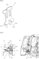
- FIG. 2 is a perspective view of a front part 10.1 of a support plate 10 belonging to the device of the invention, and the picture 3 is a perspective view of a rear part 10.2 of the support plate 10.
- the device of the invention further comprises the support plate 10 configured to rest against the opening of the vehicle body.
- the support plate 10 comprises at least one opening forming the edge of the opening.
- the support plate 10 comprises two openings 10.3 and 10.4.
- the support plate comprises in line with its rear part 10.2, respectively at two opposite edges corresponding to an upper edge and a lower edge, two hooks 10.5 and 10.6 able to engage with the opening in order to maintain the plate of support 10 against said opening.
- the rear part 10.2 of the support plate 10 comprises a flange 11 allowing the positioning of said support plate 10 on the body of the motor vehicle prior to the engagement of the hook 10.6 on a fixed edge belonging to the bodywork and which may be adjacent to the opening.
- the support plate 10 further comprises a centering pin 10.7.
- the centering pin 10.7 allows the centering of the support plate 10 in the body of the motor vehicle, thus allowing precision and repeatability of the positioning of the support plate 10 on the fixed element.
- the support plate 10 further comprises on its front part 10.1, a handle 10.8 allowing the manual manipulation of said support plate 10 in order to facilitate the movement of the latter and its reuse for several bodies.
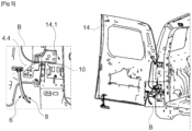
- FIG. 4 And 5 schematically illustrate the door of the motor vehicle held respectively in the open position at 90° and 120° by means of the device 2 of the invention.
- the opening of the vehicle is a rear door 14 of a vehicle preferably being of the utility type and comprising the device 2 of the invention.
- the left part of the figure 4 represents an enlarged portion A of the device 2, the latter is in a position holding the leaf 14 at 90° relative to the bodywork.
- the distal portion of the arm 6 is engaged in the opening 10.3 of the bearing plate 10 so that the bearing surface 8.1 of the shoulder is in contact with the edge of opening 10.3. In this configuration, the distal portion of the arm 6 passes through the opening 14.1 of the bodywork.
- the device 2 of the invention can be used and can hold the opening 14 in a right or left side of the vehicle.
- the opening 14 is located to the left of the motor vehicle.
- the distal portion of the arm 6 is configured to engage in the opening 10.4 in the case where the opening 14 is located to the right of the motor vehicle.
- the device 2 of the invention allows during a holding position of the opening 14 illustrated in figure 4 , to be able to carry out assembly operations on the body of the motor vehicle.
- the bodywork can undergo an application of at least one coating on the bodywork of the motor vehicle, for example, the application of a coat of primer and/or paint and/or varnish.
- the use of the device of the invention makes it possible to cover the entirety of the bodywork during the operations of applying at least one coating.
- the device 2 can be reused several times thanks to its ability to undergo a treatment such as sandblasting for example.
- the opening 14 is in a 120° opening position and in which the distal portion 6.2 of the arm 6 is disengaged from the opening 14.1 and particularly disengaged from the opening 10.3 of the support plate 10.
- the left part of the figure 5 represents an enlarged portion B of the device 2, and in which the disengagement is illustrated.
- the disengagement can occur after a pushing movement of the leaf 14 towards the outside in order to enlarge the angle of the opening of the latter, such a pushing movement can be easily ensured by a robotic arm.
- the second articulation allows the arm 6 to pivot through an angle of 90° around the second axis 4.4 under the effect of gravity as soon as the arm 6 disengages with respect to the support plate 10.
- the second joint of arm 6 comprises an angle limiter 4.5 making it possible to limit the rotation of said arm 6 to 90° just after its disengagement.
- the rotation of the arm 6 following its disengagement at 120° makes it possible to completely close the opening 14, so that an outer surface (not shown) of the opening 14 can be treated, in particular during a method for applying at least one coating to the bodywork of the motor vehicle.
- the closing of the opening 14 can be easily ensured by the robotic arm.
- the device 2 of the invention can advantageously remain attached to the motor vehicle when the opening 14 is closed without damaging the bodywork of said vehicle.
Landscapes
- Engineering & Computer Science (AREA)
- Mechanical Engineering (AREA)
- Manufacturing & Machinery (AREA)
- Chemical & Material Sciences (AREA)
- Combustion & Propulsion (AREA)
- Transportation (AREA)
- Automobile Manufacture Line, Endless Track Vehicle, Trailer (AREA)
- Power-Operated Mechanisms For Wings (AREA)
Abstract
Description
- La présente invention concerne le domaine des véhicules automobiles. L'invention concerne notamment le domaine de verrouillage provisoire des éléments ouvrants sur des éléments fixes des carrosseries des véhicules automobiles.
- Lors de l'assemblage des véhicules automobiles dans les chaînes de montage, chaque carrosserie reçoit un traitement spécial afin de la protéger de toute éventuelle corrosion, entre autres, et cela, en appliquant un ou plusieurs revêtements, tels que des revêtements de protection ou l'application d'une couche de peinture et de vernis.
- À cet égard, un tel traitement est généralement reçu par la carrosserie préalablement à la fixation définitive d'un élément ouvrant du véhicule automobile, tel qu'une porte, un capot, ou un hayon, par exemple, sur un élément fixe de la carrosserie du véhicule automobile. En effet, lors de ces traitements, les éléments ouvrants ne sont pas encore équipés de dispositifs de verrouillage définitifs, tels que des serrures.
- C'est la raison pour laquelle des dispositifs de verrouillage provisoire sont prévus, permettant ainsi le maintien de l'ouvrant dans une position ouverte ou demi-fermée par rapport à l'élément fixe auquel il sera fixé.
- Il est connu de l'état de l'art d'utiliser des dispositifs de verrouillage provisoires qui sont généralement interposés entre l'ouvrant et la carrosserie. Toutefois, avec la robotisation croissante des lignes de production automobiles, les dispositifs de verrouillage actuels ne permettent pas d'assurer une automatisation complète des opérations traitements de carrosserie en ce qu'ils nécessitent une intervention humaine répétitive, notamment lors des traitements d'application des revêtements de protection dans lesquels il est parfois nécessaire de modifier la position d'ouverture de l'ouvrant afin de permettre au robot pulvérisateur d'atteindre toutes les surfaces de la carrosserie.
- Le document de brevet publié
FR 2 893 300 A1 - De plus, le dispositif d'écartement du document
FR 2 893 300 A1 - Les solutions proposées dans l'état de l'art présent une marge d'amélioration et nécessitent une adaptation aux besoins accrus en robotisation des lignes de production actuelles des véhicules automobiles.
- La présente invention a pour objectif de pallier au moins un des inconvénients de l'état de la technique susmentionné. Plus particulièrement, l'invention a pour objectif de proposer un dispositif permettant le maintien provisoire d'un ouvrant de carrosserie de véhicule automobile en position d'ouverture.
- À cet effet, l'invention a pour objet un dispositif pour un maintien provisoire d'un ouvrant de carrosserie de véhicule automobile, comprenant une platine de fixation ; et un bras s'étendant depuis la platine de fixation ; remarquable en ce que le bras est articulé sur la platine de fixation et comprend, à distance de ladite platine de fixation, un épaulement apte à venir en appui contre un bord d'un ajour dans la carrosserie.
- Selon un mode de réalisation, l'épaulement forme au moins une surface d'appui perpendiculaire à une direction générale du bras.
- Selon un mode de réalisation, la direction générale du bras forme une courbe dans un plan, l'au moins une surface d'appui comprenant deux surfaces d'appui de part et d'autre dudit plan.
- Selon un mode de réalisation, l'au moins un épaulement est à distance d'une extrémité distale du bras, de manière à ce qu'une portion distale dudit bras traverse l'ajour lorsque l'épaulement est en appui contre le bord dudit ajour.
- Selon un mode de réalisation, l'articulation entre le bras et la platine de fixation permet une rotation suivant deux axes de rotation perpendiculaires. De préférence, les deux axes de rotation sont concourants, permettant de manière avantageuse, d'assurer l'articulation du bras dans un encombrement réduit.
- Selon un mode de réalisation, la platine de fixation comprend un orifice de fixation à l'ouvrant et/ou un pion d'engagement dans ledit ouvrant.
- Selon un mode de réalisation, le dispositif de l'invention comprend, en outre, une platine d'appui contre l'ajour, avec au moins une ouverture formant le bord de l'ajour. Préférentiellement, la platine d'appui comprend deux ouvertures.
- Selon un mode de réalisation, la platine d'appui comprend, respectivement à deux bords opposés, deux crochets aptes à s'engager avec l'ajour afin de maintenir ladite platine d'appui contre ledit ajour.
- L'invention a également pour objet un procédé d'assemblage d'un véhicule automobile, comprenant les étapes suivantes :
- ouverture d'un ouvrant de carrosserie du véhicule automobile en l'absence de tirant dudit ouvrant ;
- réalisation d'opérations d'assemblage suite à ladite ouverture ; et
- fermeture de l'ouvrant ;
- De préférence, le dispositif de l'invention comprend, en outre, une platine d'appui contre l'ajour, ladite platine d'appui comprenant au moins une ouverture formant le bord de l'ajour. À cet effet, l'épaulement est mis en appui contre un bord de l'au moins une ouverture.
- Selon un mode de réalisation, l'étape de fermeture de l'ouvrant comprend un mouvement d'ouverture supplémentaire de l'ouvrant de manière à désengager le bras de l'ajour, suivi d'un mouvement de fermeture de l'ouvrant.
- Avantageusement, le dispositif de l'invention est configuré pour faciliter la réalisation d'opérations d'assemblage sur le véhicule automobile suite au maintien de l'ouvrant en position d'ouverture, ledit dispositif permet également de faciliter la manipulation de l'ouvrant par un bras robotisé.
-
- [
Fig 1 ] représente une vue en perspective d'un dispositif de maintien provisoire d'un ouvrant de carrosserie de véhicule automobile ; - [
Fig 2 ] est une vue en perspective d'une partie avant d'une platine d'appui appartenant au dispositif de l'invention ; - [
Fig 3 ] est une vue en perspective d'une partie arrière de la platine d'appui ; - [
Fig 4 ] illustre schématiquement un ouvrant d'un véhicule automobile maintenu en position ouverte à 90° au moyen du dispositif de l'invention ; - [
Fig 5 ] illustre schématiquement l'ouvrant en position ouverte à 120° et comprenant le dispositif de l'invention. - La
figure 1 représente une vue en perspective d'un dispositif de maintien provisoire d'un ouvrant de carrosserie de véhicule automobile en position ouverte En référence à lafigure 1 , le dispositif comprend une platine de fixation 4 à partir de laquelle s'étend un bras 6. La platine de fixation 4 est configurée pour être fixée à l'ouvrant du véhicule automobile. - À cet égard, la platine de fixation 4 comprend préférentiellement un orifice 4.1 de fixation à l'ouvrant permettant ainsi le vissage de la platine de fixation 4 sur l'ouvrant. De préférence, la platine de fixation 4 comprend un pion 4.2 d'engagement dans l'ouvrant.
- Avantageusement, le pion d'engagement 4.2 permet le centrage de la pièce de fixation 4 dans l'ouvrant préalablement au vissage, permettant ainsi une mise en positon facilitée et une répétabilité de fixation de la platine 4 sur les ouvrants des véhicules automobiles.
- Le bras 6 comprend une partie proximale 6.1 articulée sur la platine de fixation 4 et présentant avec cette dernière une première articulation ayant un premier axe 4.3.
- La platine de fixation 4 comprend une deuxième articulation avec le bras 6, cette dernière comprenant un deuxième axe 4.4. Préférentiellement, les premier 4.3 et deuxième axe 4.4 étant perpendiculaires.
- Les première et deuxième articulations ne se limitent pas au seul exemple illustré dans la
figure 1 . En effet, lesdites articulations peuvent être assurées par une rotule par exemple ou par toute autre liaison mécanique comprenant deux axes de rotation ou plus. - Le bras 6 comprend une portion distale 6.2, ainsi qu'un épaulement 8 apte à venir en appui contre un bord d'un ajour dans la carrosserie. À cet effet, l'épaulement 8 est à distance de la platine de fixation 4, et notamment entre la partie distale 6.2 et ladite platine de fixation 4, et particulièrement, l'épaulement 8 est disposé entre une extrémité distale 6.3 et le premier axe 4.3.
- Préférentiellement, l'épaulement 8 est distant de l'extrémité distale 6.3 d'une distance correspondant à environ 10% de la longueur totale du bras 6. Le terme environ correspond à ±5% de la valeur nominale.
- La direction générale du bras 6 peut former une courbe dans un plan. En effet, le bras 6 comprend de préférence une forme arquée.
- L'épaulement forme au moins une surface d'appui perpendiculaire à une direction générale du bras. Préférentiellement, l'au moins une surface d'appui comprenant deux surfaces d'appui 8.1 et 8.2 de part et d'autre du bras 6.
- La
figure 2 est une vue en perspective d'une partie avant 10.1 d'une platine d'appui 10 appartenant au dispositif de l'invention, et lafigure 3 est une vue en perspective d'une partie arrière 10.2 de la platine d'appui 10. - En référence aux
figures 2 et3 , le dispositif de l'invention comprend en outre la platine d'appui 10 configurée pour être en appui contre l'ajour de la carrosserie du véhicule. - Dans cette configuration, la platine d'appui 10 comprend au moins une ouverture formant le bord de l'ajour. Préférentiellement, la platine d'appui 10 comprend deux ouvertures 10.3 et 10.4.
- La platine d'appui comprend au droit de sa partie arrière 10.2, respectivement à deux bords opposés correspondant à un bord supérieur et un bord inférieur, deux crochets 10.5 et 10.6 aptes à s'engager avec l'ajour afin de maintenir la platine d'appui 10 contre ledit ajour.
- De préférence, la partie arrière 10.2 de la platine d'appui 10 comprend une bride 11 permettant la mise en position de ladite platine d'appui 10 sur la carrosserie du véhicule automobile préalablement à l'engagement du crochet 10.6 sur un bord fixe appartenant à la carrosserie et qui peut être adjacent de l'ajour.
- Préférablement, la platine d'appui 10 comprend en outre un pion de centrage 10.7. Avantageusement, le pion de centrage 10.7 permet le centrage de la platine d'appui 10 dans la carrosserie du véhicule automobile, permettant ainsi une précision et une répétabilité du positionnement de la platine d'appui 10 sur l'élément fixe.
- De préférence, la platine d'appui 10 comprend en outre sur sa partie avant 10.1, une poignée 10.8 permettant la manipulation manuelle de ladite platine d'appui 10 afin de faciliter le déplacement de cette dernière et sa réutilisation pour plusieurs carrosseries.
- Les
figures 4 et5 , illustrent de manière schématique l'ouvrant du véhicule automobile maintenu respectivement en position ouverte à 90° et à 120° au moyen du dispositif 2 de l'invention. - En référence à la
figure 4 , et particulièrement à la partie droite de lafigure 4 , dans laquelle l'ouvrant du véhicule est une porte arrière 14 d'un véhicule étant préférentiellement de type utilitaire et comprenant le dispositif 2 de l'invention. - La partie gauche de la
figure 4 représente une portion agrandie A du dispositif 2, ce dernier est dans une position de maintien de l'ouvrant 14 à 90° par rapport à la carrosserie. - En référence à la portion agrandie A, la portion distale du bras 6 est engagée dans l'ouverture 10.3 de la platine d'appui 10 de manière à ce que la surface d'appui 8.1 de l'épaulement soit en contact avec le bord de l'ouverture 10.3. Dans cette configuration, la portion distale du bras 6 traverse l'ajour 14.1 de la carrosserie.
- Il est à noter que le dispositif 2 de l'invention est utilisable et peut maintenir l'ouvrant 14 dans un côté droit ou gauche du véhicule. Dans la configuration illustrée dans la
figure 4 et5 , l'ouvrant 14 se situe à gauche du véhicule automobile. De préférence, la portion distale du bras 6 est configurée pour s'engager dans l'ouverture 10.4 dans le cas où l'ouvrant 14 se situe à droite du véhicule automobile. - Le dispositif 2 de l'invention permet lors d'une position de maintien de l'ouvrant 14 illustrée à la
figure 4 , de pouvoir procéder à la réalisation d'opérations d'assemblage sur la carrosserie du véhicule automobile. - Préférentiellement, parmi les opérations d'assemblage, la carrosserie peut subir une application d'au moins un revêtement sur la carrosserie du véhicule automobile, par exemple, l'application d'une couche d'apprêt et/ou de peinture et/ou de vernis.
- De façon avantageuse, l'utilisation du dispositif de l'invention permet de couvrir l'intégralité de la carrosserie lors des opérations d'application d'au moins un revêtement.
- Avantageusement, le dispositif 2 peut être réutilisé plusieurs fois grâce à sa faculté de subir un traitement tel que le sablage par exemple.
- En référence à la
figure 5 , l'ouvrant 14 est dans une position d'ouverture à 120° et dans laquelle la portion distale 6.2 du bras 6 est désengagée de l'ajour 14.1 et particulièrement désengagée de l'ouverture 10.3 de la platine d'appui 10. - La partie gauche de la
figure 5 représente une portion agrandie B du dispositif 2, et dans laquelle le désengagement est illustré. - En effet, le désengagement peut survenir après un mouvement de poussée de l'ouvrant 14 vers l'extérieur afin d'agrandir l'angle de l'ouverture de ce dernier, un tel mouvement de poussée peut être assuré facilement par un bras robotisé.
- À cet effet, la deuxième articulation permet au bras 6 de pivoter d'un angle de 90° autour du deuxième axe 4.4 sous l'effet de la gravité dès le désengagement du bras 6 par rapport à la platine d'appui 10.
- Préférentiellement, la deuxième articulation du bras 6 comprend un limiteur d'angle 4.5 permettant de limiter la rotation dudit bras 6 à 90° juste après son désengagement.
- Avantageusement, la rotation du bras 6 suite à son désengagement à 120°, permet de fermer complètement l'ouvrant 14, de manière à ce qu'une surface extérieure (non illustrée) de l'ouvrant 14 puisse être traitée, notamment lors d'un procédé d'application d'au moins un revêtement sur la carrosserie du véhicule automobile.
- De manière avantageuse, la fermeture de l'ouvrant 14 peut être facilement assurée par le bras robotisé. À cet effet, le dispositif 2 de l'invention peut avantageusement rester fixé sur le véhicule automobile lors de la fermeture de l'ouvrant 14 sans abîmer la carrosserie dudit véhicule.
Claims (10)
- Dispositif (2) pour un maintien provisoire d'un ouvrant (14) de carrosserie de véhicule automobile, comprenant :- une platine de fixation (4) ; et- un bras (6) s'étendant depuis la platine de fixation (4) ;caractérisé en ce que
le bras (6) est articulé sur la platine de fixation (4) et comprend à distance de ladite platine de fixation, un épaulement (8) apte à venir en appui contre un bord d'un ajour (14.1) dans la carrosserie. - Dispositif (2) selon la revendication 1, dans lequel l'épaulement (8) forme au moins une surface d'appui (8.1, 8.2) perpendiculaire à une direction générale du bras (6).
- Dispositif (2) selon la revendication 2, dans lequel la direction générale du bras (6) forme une courbe dans un plan, l'au moins une surface d'appui (8.1, 8.2) comprenant deux surfaces d'appui (8.1, 8.2) de part et d'autre dudit plan.
- Dispositif (2) selon l'une des revendications 1 à 3, dans lequel l'épaulement (8) est à distance d'une extrémité distale (6.3) du bras (6), de manière à ce qu'une portion distale (6.2) dudit bras (6) traverse l'ajour (14.1) lorsque l'épaulement (8) est en appui contre le bord dudit ajour (14.1).
- Dispositif (2) selon l'une des revendications 1 à 4, dans lequel l'articulation entre le bras (6) et la platine de fixation (4) permet une rotation suivant deux axes de rotation perpendiculaires.
- Dispositif (2) selon l'une des revendications 1 à 5, dans lequel la platine de fixation (4) comprend un orifice (4.1) de fixation à l'ouvrant (14) et/ou un pion d'engagement (4.2) dans ledit ouvrant (14).
- Dispositif (2) selon l'une des revendications 1 à 6, comprenant, en outre :- une platine d'appui (14) contre l'ajour (14.1), avec au moins une ouverture (10.3, 10.4) formant le bord de l'ajour (14.1).
- Dispositif (2) selon la revendication 7, dans lequel la platine d'appui (10) comprend, respectivement à deux bords opposés, deux crochets (10.5, 10.6) aptes à s'engager avec l'ajour (14.1) afin de maintenir ladite platine d'appui (10) contre ledit ajour (14.1).
- Procédé d'assemblage d'un véhicule automobile, comprenant les étapes suivantes :- ouverture d'un ouvrant (14) de carrosserie du véhicule automobile en l'absence de tirant dudit ouvrant (14) ;- réalisation d'opérations d'assemblage suite à ladite ouverture ; et- fermeture de l'ouvrant ;caractérisé en ce que l'étape d'ouverture comprend l'utilisation d'un dispositif (2) suivant l'une des revendications 1 à 8 où la platine de fixation (4) est fixée à l'ouvrant (14) et l'épaulement (8) est mis en appui contre un bord d'un ajour (14.1) de la carrosserie.
- Procédé selon la revendication 9, dans lequel l'étape de fermeture de l'ouvrant (14) comprend un mouvement d'ouverture supplémentaire de l'ouvrant (14) de manière à désengager le bras (6) de l'ajour (14.1), suivi d'un mouvement de fermeture de l'ouvrant (14).
Applications Claiming Priority (1)
| Application Number | Priority Date | Filing Date | Title |
|---|---|---|---|
| FR2201755A FR3133046A1 (fr) | 2022-02-28 | 2022-02-28 | Dispositif de maintien provisoire d’un élément ouvrant à 90° par rappport à un élément fixe |
Publications (2)
| Publication Number | Publication Date |
|---|---|
| EP4234865A1 true EP4234865A1 (fr) | 2023-08-30 |
| EP4234865B1 EP4234865B1 (fr) | 2024-08-21 |
Family
ID=81345989
Family Applications (1)
| Application Number | Title | Priority Date | Filing Date |
|---|---|---|---|
| EP23155714.1A Active EP4234865B1 (fr) | 2022-02-28 | 2023-02-09 | Dispositif de maintien provisoire d'un élément ouvrant à 90° par rappport à un élément fixe |
Country Status (2)
| Country | Link |
|---|---|
| EP (1) | EP4234865B1 (fr) |
| FR (1) | FR3133046A1 (fr) |
Cited By (1)
| Publication number | Priority date | Publication date | Assignee | Title |
|---|---|---|---|---|
| FR3154375A1 (fr) * | 2023-10-24 | 2025-04-25 | Psa Automobiles Sa | Dispositif de maintien d’un hayon de véhicule en position ouverte |
Citations (6)
| Publication number | Priority date | Publication date | Assignee | Title |
|---|---|---|---|---|
| US1379959A (en) * | 1920-02-09 | 1921-05-31 | John F Brodowski | Sash-fastener |
| US2035944A (en) * | 1935-03-11 | 1936-03-31 | Montague P Browne | Brace or stay for hinged covers and the like |
| GB1187345A (en) * | 1967-04-28 | 1970-04-08 | Desmond Edward Charles Webster | Improvements in Windows and Opening and Closing Means therefor |
| FR2893300A1 (fr) | 2005-11-15 | 2007-05-18 | Exsto Soc Par Actions Simplifi | Dispositif d'ecartement securise a l'arrachement |
| US20090045654A1 (en) * | 2005-10-28 | 2009-02-19 | Honda Motor Co., Ltd. | Door closure prevention tool and vehicle body coating method using the tool |
| EP2182146A1 (fr) * | 2008-10-14 | 2010-05-05 | Claudio Nappo | Dispositif pour maintenir la portière d'un véhicule motorisé en position ouverte durant le procédé de fabrication |
-
2022
- 2022-02-28 FR FR2201755A patent/FR3133046A1/fr active Pending
-
2023
- 2023-02-09 EP EP23155714.1A patent/EP4234865B1/fr active Active
Patent Citations (6)
| Publication number | Priority date | Publication date | Assignee | Title |
|---|---|---|---|---|
| US1379959A (en) * | 1920-02-09 | 1921-05-31 | John F Brodowski | Sash-fastener |
| US2035944A (en) * | 1935-03-11 | 1936-03-31 | Montague P Browne | Brace or stay for hinged covers and the like |
| GB1187345A (en) * | 1967-04-28 | 1970-04-08 | Desmond Edward Charles Webster | Improvements in Windows and Opening and Closing Means therefor |
| US20090045654A1 (en) * | 2005-10-28 | 2009-02-19 | Honda Motor Co., Ltd. | Door closure prevention tool and vehicle body coating method using the tool |
| FR2893300A1 (fr) | 2005-11-15 | 2007-05-18 | Exsto Soc Par Actions Simplifi | Dispositif d'ecartement securise a l'arrachement |
| EP2182146A1 (fr) * | 2008-10-14 | 2010-05-05 | Claudio Nappo | Dispositif pour maintenir la portière d'un véhicule motorisé en position ouverte durant le procédé de fabrication |
Cited By (1)
| Publication number | Priority date | Publication date | Assignee | Title |
|---|---|---|---|---|
| FR3154375A1 (fr) * | 2023-10-24 | 2025-04-25 | Psa Automobiles Sa | Dispositif de maintien d’un hayon de véhicule en position ouverte |
Also Published As
| Publication number | Publication date |
|---|---|
| EP4234865B1 (fr) | 2024-08-21 |
| FR3133046A1 (fr) | 2023-09-01 |
Similar Documents
| Publication | Publication Date | Title |
|---|---|---|
| EP3300967B1 (fr) | Adaptateur constitutif d'un systeme d'essuyage | |
| FR2533616A1 (fr) | Charniere de porte decrochable | |
| EP4234865B1 (fr) | Dispositif de maintien provisoire d'un élément ouvrant à 90° par rappport à un élément fixe | |
| EP3147203A1 (fr) | Dispositif de verrouillage d'un element mobile tel qu'une porte d'un aeronef et aeronef equipe dudit dispositif de verrouillage | |
| EP3678879B1 (fr) | Mécanisme pour un coffre à deux ouvrants d'un véhicule automobile | |
| FR2638126A3 (fr) | Dispositif de fixation de portes et/ou d'abattants de vehicules pendant le montage du vehicule | |
| EP2911803B1 (fr) | Paumelles pour montage provisoire d'une portiere sur un chassis de vehicule | |
| FR3009329A1 (fr) | Dispositif d’arret de porte provisoire avec axe provisoire a dents de serrage | |
| EP2318622B1 (fr) | Dispositif de fermeture provisoire d'un element ouvrant sur un element support | |
| EP3636473B1 (fr) | Caisse de véhicule automobile équipée temporairement d'une portière latérale | |
| EP0797718B1 (fr) | Arret de porte provisoire pour charniere d'une porte de vehicule automobile et dispositif de fixation d'un tel arret de porte provisoire | |
| EP1948499B1 (fr) | Dispositif d'ecartement securise a l'arrachement | |
| EP3412523B1 (fr) | Sous-ensemble de timonerie et timonerie maintenus dans une position de transport à l aide d'un élément de blocage, et procédé de blocage de cette timonerie à l aide d'un tel élément de blocage | |
| EP0568399A1 (fr) | Dispositif pour le positionnement et le verrouillage en position d'une caisse de véhicule automobile sur une structure de manutention et structure de manutention | |
| EP0930412A1 (fr) | Charnière de porte à cran de retenue, notamment pour un véhicule automobile | |
| EP4008869A1 (fr) | Dispositif d arrêt pour une charnière de véhicule | |
| WO2003004804A1 (fr) | Dispositif d'ecartement et de verrouillage provisoire d'un ouvrant sur une caisse de vehicule automobile | |
| EP4257386A1 (fr) | Côté de caisse de véhicule comprenant un moyen de retenue d'une porte coulissante en cas de choc transversal depuis l habitacle vers l extérieur | |
| FR3160667A1 (fr) | Dispositif pour la retenue temporaire d’un ouvrant de carrosserie | |
| EP4696464A1 (fr) | Outil destine a equiper une extremite d'un bras poly-articule d'un robot | |
| FR3119782A1 (fr) | Outil de manipulation et de positionnement d’un ouvrant de véhicule | |
| FR3160720A1 (fr) | Dispositif bistable pour la retenue temporaire d’un ouvrant de carrosserie | |
| FR2994931A1 (fr) | Dispositif de support et de maintien d'un volet de coffre et procede de montage d'un vehicule mettant en oeuvre ce dispositif. | |
| WO2020169924A1 (fr) | Couvercle pour cuve comprenant un mecanisme de verrouillage automatique | |
| EP4628691A1 (fr) | Dispositif de retenue temporaire d'un ouvrant de carosserie |
Legal Events
| Date | Code | Title | Description |
|---|---|---|---|
| PUAI | Public reference made under article 153(3) epc to a published international application that has entered the european phase |
Free format text: ORIGINAL CODE: 0009012 |
|
| STAA | Information on the status of an ep patent application or granted ep patent |
Free format text: STATUS: THE APPLICATION HAS BEEN PUBLISHED |
|
| AK | Designated contracting states |
Kind code of ref document: A1 Designated state(s): AL AT BE BG CH CY CZ DE DK EE ES FI FR GB GR HR HU IE IS IT LI LT LU LV MC ME MK MT NL NO PL PT RO RS SE SI SK SM TR |
|
| RIN1 | Information on inventor provided before grant (corrected) |
Inventor name: ASTORG, ALEXANDRE Inventor name: LUELMO, EMILIO |
|
| RAP3 | Party data changed (applicant data changed or rights of an application transferred) |
Owner name: STELLANTIS AUTO SAS |
|
| STAA | Information on the status of an ep patent application or granted ep patent |
Free format text: STATUS: REQUEST FOR EXAMINATION WAS MADE |
|
| 17P | Request for examination filed |
Effective date: 20240207 |
|
| RBV | Designated contracting states (corrected) |
Designated state(s): AL AT BE BG CH CY CZ DE DK EE ES FI FR GB GR HR HU IE IS IT LI LT LU LV MC ME MK MT NL NO PL PT RO RS SE SI SK SM TR |
|
| RIC1 | Information provided on ipc code assigned before grant |
Ipc: E05B 63/04 20060101ALN20240312BHEP Ipc: B62D 65/02 20060101ALI20240312BHEP Ipc: E05C 17/12 20060101ALI20240312BHEP Ipc: E05C 17/08 20060101ALI20240312BHEP Ipc: B62D 65/06 20060101ALI20240312BHEP Ipc: B05B 13/02 20060101ALI20240312BHEP Ipc: E05C 21/00 20060101AFI20240312BHEP |
|
| GRAP | Despatch of communication of intention to grant a patent |
Free format text: ORIGINAL CODE: EPIDOSNIGR1 |
|
| STAA | Information on the status of an ep patent application or granted ep patent |
Free format text: STATUS: GRANT OF PATENT IS INTENDED |
|
| INTG | Intention to grant announced |
Effective date: 20240423 |
|
| GRAS | Grant fee paid |
Free format text: ORIGINAL CODE: EPIDOSNIGR3 |
|
| GRAA | (expected) grant |
Free format text: ORIGINAL CODE: 0009210 |
|
| STAA | Information on the status of an ep patent application or granted ep patent |
Free format text: STATUS: THE PATENT HAS BEEN GRANTED |
|
| AK | Designated contracting states |
Kind code of ref document: B1 Designated state(s): AL AT BE BG CH CY CZ DE DK EE ES FI FR GB GR HR HU IE IS IT LI LT LU LV MC ME MK MT NL NO PL PT RO RS SE SI SK SM TR |
|
| REG | Reference to a national code |
Ref country code: GB Ref legal event code: FG4D Free format text: NOT ENGLISH |
|
| REG | Reference to a national code |
Ref country code: CH Ref legal event code: EP |
|
| REG | Reference to a national code |
Ref country code: DE Ref legal event code: R096 Ref document number: 602023000408 Country of ref document: DE |
|
| REG | Reference to a national code |
Ref country code: IE Ref legal event code: FG4D Free format text: LANGUAGE OF EP DOCUMENT: FRENCH |
|
| REG | Reference to a national code |
Ref country code: DE Ref legal event code: R084 Ref document number: 602023000408 Country of ref document: DE |
|
| REG | Reference to a national code |
Ref country code: LT Ref legal event code: MG9D |
|
| REG | Reference to a national code |
Ref country code: NL Ref legal event code: MP Effective date: 20240821 |
|
| PG25 | Lapsed in a contracting state [announced via postgrant information from national office to epo] |
Ref country code: NO Free format text: LAPSE BECAUSE OF FAILURE TO SUBMIT A TRANSLATION OF THE DESCRIPTION OR TO PAY THE FEE WITHIN THE PRESCRIBED TIME-LIMIT Effective date: 20241121 |
|
| REG | Reference to a national code |
Ref country code: AT Ref legal event code: MK05 Ref document number: 1715625 Country of ref document: AT Kind code of ref document: T Effective date: 20240821 |
|
| PG25 | Lapsed in a contracting state [announced via postgrant information from national office to epo] |
Ref country code: PT Free format text: LAPSE BECAUSE OF FAILURE TO SUBMIT A TRANSLATION OF THE DESCRIPTION OR TO PAY THE FEE WITHIN THE PRESCRIBED TIME-LIMIT Effective date: 20241223 Ref country code: PL Free format text: LAPSE BECAUSE OF FAILURE TO SUBMIT A TRANSLATION OF THE DESCRIPTION OR TO PAY THE FEE WITHIN THE PRESCRIBED TIME-LIMIT Effective date: 20240821 Ref country code: NL Free format text: LAPSE BECAUSE OF FAILURE TO SUBMIT A TRANSLATION OF THE DESCRIPTION OR TO PAY THE FEE WITHIN THE PRESCRIBED TIME-LIMIT Effective date: 20240821 Ref country code: FI Free format text: LAPSE BECAUSE OF FAILURE TO SUBMIT A TRANSLATION OF THE DESCRIPTION OR TO PAY THE FEE WITHIN THE PRESCRIBED TIME-LIMIT Effective date: 20240821 |
|
| PG25 | Lapsed in a contracting state [announced via postgrant information from national office to epo] |
Ref country code: BG Free format text: LAPSE BECAUSE OF FAILURE TO SUBMIT A TRANSLATION OF THE DESCRIPTION OR TO PAY THE FEE WITHIN THE PRESCRIBED TIME-LIMIT Effective date: 20240821 |
|
| PG25 | Lapsed in a contracting state [announced via postgrant information from national office to epo] |
Ref country code: LV Free format text: LAPSE BECAUSE OF FAILURE TO SUBMIT A TRANSLATION OF THE DESCRIPTION OR TO PAY THE FEE WITHIN THE PRESCRIBED TIME-LIMIT Effective date: 20240821 |
|
| PG25 | Lapsed in a contracting state [announced via postgrant information from national office to epo] |
Ref country code: IS Free format text: LAPSE BECAUSE OF FAILURE TO SUBMIT A TRANSLATION OF THE DESCRIPTION OR TO PAY THE FEE WITHIN THE PRESCRIBED TIME-LIMIT Effective date: 20241221 Ref country code: AT Free format text: LAPSE BECAUSE OF FAILURE TO SUBMIT A TRANSLATION OF THE DESCRIPTION OR TO PAY THE FEE WITHIN THE PRESCRIBED TIME-LIMIT Effective date: 20240821 |
|
| PG25 | Lapsed in a contracting state [announced via postgrant information from national office to epo] |
Ref country code: HR Free format text: LAPSE BECAUSE OF FAILURE TO SUBMIT A TRANSLATION OF THE DESCRIPTION OR TO PAY THE FEE WITHIN THE PRESCRIBED TIME-LIMIT Effective date: 20240821 |
|
| PG25 | Lapsed in a contracting state [announced via postgrant information from national office to epo] |
Ref country code: RS Free format text: LAPSE BECAUSE OF FAILURE TO SUBMIT A TRANSLATION OF THE DESCRIPTION OR TO PAY THE FEE WITHIN THE PRESCRIBED TIME-LIMIT Effective date: 20241121 Ref country code: ES Free format text: LAPSE BECAUSE OF FAILURE TO SUBMIT A TRANSLATION OF THE DESCRIPTION OR TO PAY THE FEE WITHIN THE PRESCRIBED TIME-LIMIT Effective date: 20240821 |
|
| PG25 | Lapsed in a contracting state [announced via postgrant information from national office to epo] |
Ref country code: RS Free format text: LAPSE BECAUSE OF FAILURE TO SUBMIT A TRANSLATION OF THE DESCRIPTION OR TO PAY THE FEE WITHIN THE PRESCRIBED TIME-LIMIT Effective date: 20241121 Ref country code: PT Free format text: LAPSE BECAUSE OF FAILURE TO SUBMIT A TRANSLATION OF THE DESCRIPTION OR TO PAY THE FEE WITHIN THE PRESCRIBED TIME-LIMIT Effective date: 20241223 Ref country code: PL Free format text: LAPSE BECAUSE OF FAILURE TO SUBMIT A TRANSLATION OF THE DESCRIPTION OR TO PAY THE FEE WITHIN THE PRESCRIBED TIME-LIMIT Effective date: 20240821 Ref country code: NO Free format text: LAPSE BECAUSE OF FAILURE TO SUBMIT A TRANSLATION OF THE DESCRIPTION OR TO PAY THE FEE WITHIN THE PRESCRIBED TIME-LIMIT Effective date: 20241121 Ref country code: NL Free format text: LAPSE BECAUSE OF FAILURE TO SUBMIT A TRANSLATION OF THE DESCRIPTION OR TO PAY THE FEE WITHIN THE PRESCRIBED TIME-LIMIT Effective date: 20240821 Ref country code: LV Free format text: LAPSE BECAUSE OF FAILURE TO SUBMIT A TRANSLATION OF THE DESCRIPTION OR TO PAY THE FEE WITHIN THE PRESCRIBED TIME-LIMIT Effective date: 20240821 Ref country code: IS Free format text: LAPSE BECAUSE OF FAILURE TO SUBMIT A TRANSLATION OF THE DESCRIPTION OR TO PAY THE FEE WITHIN THE PRESCRIBED TIME-LIMIT Effective date: 20241221 Ref country code: HR Free format text: LAPSE BECAUSE OF FAILURE TO SUBMIT A TRANSLATION OF THE DESCRIPTION OR TO PAY THE FEE WITHIN THE PRESCRIBED TIME-LIMIT Effective date: 20240821 Ref country code: FI Free format text: LAPSE BECAUSE OF FAILURE TO SUBMIT A TRANSLATION OF THE DESCRIPTION OR TO PAY THE FEE WITHIN THE PRESCRIBED TIME-LIMIT Effective date: 20240821 Ref country code: ES Free format text: LAPSE BECAUSE OF FAILURE TO SUBMIT A TRANSLATION OF THE DESCRIPTION OR TO PAY THE FEE WITHIN THE PRESCRIBED TIME-LIMIT Effective date: 20240821 Ref country code: BG Free format text: LAPSE BECAUSE OF FAILURE TO SUBMIT A TRANSLATION OF THE DESCRIPTION OR TO PAY THE FEE WITHIN THE PRESCRIBED TIME-LIMIT Effective date: 20240821 Ref country code: AT Free format text: LAPSE BECAUSE OF FAILURE TO SUBMIT A TRANSLATION OF THE DESCRIPTION OR TO PAY THE FEE WITHIN THE PRESCRIBED TIME-LIMIT Effective date: 20240821 |
|
| PG25 | Lapsed in a contracting state [announced via postgrant information from national office to epo] |
Ref country code: RO Free format text: LAPSE BECAUSE OF FAILURE TO SUBMIT A TRANSLATION OF THE DESCRIPTION OR TO PAY THE FEE WITHIN THE PRESCRIBED TIME-LIMIT Effective date: 20240821 Ref country code: DK Free format text: LAPSE BECAUSE OF FAILURE TO SUBMIT A TRANSLATION OF THE DESCRIPTION OR TO PAY THE FEE WITHIN THE PRESCRIBED TIME-LIMIT Effective date: 20240821 Ref country code: SM Free format text: LAPSE BECAUSE OF FAILURE TO SUBMIT A TRANSLATION OF THE DESCRIPTION OR TO PAY THE FEE WITHIN THE PRESCRIBED TIME-LIMIT Effective date: 20240821 |
|
| PG25 | Lapsed in a contracting state [announced via postgrant information from national office to epo] |
Ref country code: EE Free format text: LAPSE BECAUSE OF FAILURE TO SUBMIT A TRANSLATION OF THE DESCRIPTION OR TO PAY THE FEE WITHIN THE PRESCRIBED TIME-LIMIT Effective date: 20240821 |
|
| PG25 | Lapsed in a contracting state [announced via postgrant information from national office to epo] |
Ref country code: CZ Free format text: LAPSE BECAUSE OF FAILURE TO SUBMIT A TRANSLATION OF THE DESCRIPTION OR TO PAY THE FEE WITHIN THE PRESCRIBED TIME-LIMIT Effective date: 20240821 |
|
| PG25 | Lapsed in a contracting state [announced via postgrant information from national office to epo] |
Ref country code: IT Free format text: LAPSE BECAUSE OF FAILURE TO SUBMIT A TRANSLATION OF THE DESCRIPTION OR TO PAY THE FEE WITHIN THE PRESCRIBED TIME-LIMIT Effective date: 20240821 Ref country code: SK Free format text: LAPSE BECAUSE OF FAILURE TO SUBMIT A TRANSLATION OF THE DESCRIPTION OR TO PAY THE FEE WITHIN THE PRESCRIBED TIME-LIMIT Effective date: 20240821 |
|
| REG | Reference to a national code |
Ref country code: DE Ref legal event code: R097 Ref document number: 602023000408 Country of ref document: DE |
|
| PLBE | No opposition filed within time limit |
Free format text: ORIGINAL CODE: 0009261 |
|
| STAA | Information on the status of an ep patent application or granted ep patent |
Free format text: STATUS: NO OPPOSITION FILED WITHIN TIME LIMIT |
|
| 26N | No opposition filed |
Effective date: 20250522 |
|
| PG25 | Lapsed in a contracting state [announced via postgrant information from national office to epo] |
Ref country code: SE Free format text: LAPSE BECAUSE OF FAILURE TO SUBMIT A TRANSLATION OF THE DESCRIPTION OR TO PAY THE FEE WITHIN THE PRESCRIBED TIME-LIMIT Effective date: 20240821 |
|
| PG25 | Lapsed in a contracting state [announced via postgrant information from national office to epo] |
Ref country code: MC Free format text: LAPSE BECAUSE OF FAILURE TO SUBMIT A TRANSLATION OF THE DESCRIPTION OR TO PAY THE FEE WITHIN THE PRESCRIBED TIME-LIMIT Effective date: 20240821 |
|
| PG25 | Lapsed in a contracting state [announced via postgrant information from national office to epo] |
Ref country code: LU Free format text: LAPSE BECAUSE OF NON-PAYMENT OF DUE FEES Effective date: 20250209 |
|
| REG | Reference to a national code |
Ref country code: BE Ref legal event code: MM Effective date: 20250228 |
|
| PG25 | Lapsed in a contracting state [announced via postgrant information from national office to epo] |
Ref country code: BE Free format text: LAPSE BECAUSE OF NON-PAYMENT OF DUE FEES Effective date: 20250228 |
|
| PG25 | Lapsed in a contracting state [announced via postgrant information from national office to epo] |
Ref country code: IE Free format text: LAPSE BECAUSE OF NON-PAYMENT OF DUE FEES Effective date: 20250209 |
|
| PGFP | Annual fee paid to national office [announced via postgrant information from national office to epo] |
Ref country code: DE Payment date: 20260121 Year of fee payment: 4 |
|
| PGFP | Annual fee paid to national office [announced via postgrant information from national office to epo] |
Ref country code: FR Payment date: 20260121 Year of fee payment: 4 |