EP3300967B1 - Adaptateur constitutif d'un systeme d'essuyage - Google Patents
Adaptateur constitutif d'un systeme d'essuyage Download PDFInfo
- Publication number
- EP3300967B1 EP3300967B1 EP17188098.2A EP17188098A EP3300967B1 EP 3300967 B1 EP3300967 B1 EP 3300967B1 EP 17188098 A EP17188098 A EP 17188098A EP 3300967 B1 EP3300967 B1 EP 3300967B1
- Authority
- EP
- European Patent Office
- Prior art keywords
- adapter
- wall
- side wall
- drive arm
- connector
- Prior art date
- Legal status (The legal status is an assumption and is not a legal conclusion. Google has not performed a legal analysis and makes no representation as to the accuracy of the status listed.)
- Active
Links
- 238000000034 method Methods 0.000 claims description 13
- 238000000465 moulding Methods 0.000 description 6
- 239000011521 glass Substances 0.000 description 4
- 230000033001 locomotion Effects 0.000 description 4
- 230000009467 reduction Effects 0.000 description 4
- XLYOFNOQVPJJNP-UHFFFAOYSA-N water Substances O XLYOFNOQVPJJNP-UHFFFAOYSA-N 0.000 description 3
- 229910001868 water Inorganic materials 0.000 description 3
- XECAHXYUAAWDEL-UHFFFAOYSA-N acrylonitrile butadiene styrene Chemical compound C=CC=C.C=CC#N.C=CC1=CC=CC=C1 XECAHXYUAAWDEL-UHFFFAOYSA-N 0.000 description 2
- 229920000122 acrylonitrile butadiene styrene Polymers 0.000 description 2
- 239000004676 acrylonitrile butadiene styrene Substances 0.000 description 2
- 238000005452 bending Methods 0.000 description 2
- 238000006073 displacement reaction Methods 0.000 description 2
- 230000004438 eyesight Effects 0.000 description 2
- 238000012423 maintenance Methods 0.000 description 2
- 239000000463 material Substances 0.000 description 2
- 229910052751 metal Inorganic materials 0.000 description 2
- 239000002184 metal Substances 0.000 description 2
- 239000000203 mixture Substances 0.000 description 2
- 229920006324 polyoxymethylene Polymers 0.000 description 2
- 229920002994 synthetic fiber Polymers 0.000 description 2
- 229910052782 aluminium Inorganic materials 0.000 description 1
- XAGFODPZIPBFFR-UHFFFAOYSA-N aluminium Chemical compound [Al] XAGFODPZIPBFFR-UHFFFAOYSA-N 0.000 description 1
- 238000013459 approach Methods 0.000 description 1
- 230000000903 blocking effect Effects 0.000 description 1
- 230000000295 complement effect Effects 0.000 description 1
- 239000000470 constituent Substances 0.000 description 1
- 230000001186 cumulative effect Effects 0.000 description 1
- 238000005520 cutting process Methods 0.000 description 1
- 230000006378 damage Effects 0.000 description 1
- 230000000254 damaging effect Effects 0.000 description 1
- 238000007599 discharging Methods 0.000 description 1
- 239000013013 elastic material Substances 0.000 description 1
- 229940082150 encore Drugs 0.000 description 1
- 230000001965 increasing effect Effects 0.000 description 1
- 239000007788 liquid Substances 0.000 description 1
- BASFCYQUMIYNBI-UHFFFAOYSA-N platinum Chemical compound [Pt] BASFCYQUMIYNBI-UHFFFAOYSA-N 0.000 description 1
- 229920000515 polycarbonate Polymers 0.000 description 1
- 239000004417 polycarbonate Substances 0.000 description 1
- 229920000642 polymer Polymers 0.000 description 1
- 239000002861 polymer material Substances 0.000 description 1
- -1 polyoxymethylenes Polymers 0.000 description 1
- 230000008569 process Effects 0.000 description 1
- 230000000717 retained effect Effects 0.000 description 1
- 239000002689 soil Substances 0.000 description 1
- 230000008093 supporting effect Effects 0.000 description 1
- 238000010408 sweeping Methods 0.000 description 1
Images


Classifications
-
- B—PERFORMING OPERATIONS; TRANSPORTING
- B60—VEHICLES IN GENERAL
- B60S—SERVICING, CLEANING, REPAIRING, SUPPORTING, LIFTING, OR MANOEUVRING OF VEHICLES, NOT OTHERWISE PROVIDED FOR
- B60S1/00—Cleaning of vehicles
- B60S1/02—Cleaning windscreens, windows or optical devices
- B60S1/04—Wipers or the like, e.g. scrapers
- B60S1/32—Wipers or the like, e.g. scrapers characterised by constructional features of wiper blade arms or blades
- B60S1/40—Connections between blades and arms
- B60S1/4038—Connections between blades and arms for arms provided with a channel-shaped end
- B60S1/4045—Connections between blades and arms for arms provided with a channel-shaped end comprising a detachable intermediate element mounted on the channel-shaped end
- B60S1/4048—Connections between blades and arms for arms provided with a channel-shaped end comprising a detachable intermediate element mounted on the channel-shaped end the element being provided with retention means co-operating with the channel-shaped end of the arm
-
- B—PERFORMING OPERATIONS; TRANSPORTING
- B60—VEHICLES IN GENERAL
- B60S—SERVICING, CLEANING, REPAIRING, SUPPORTING, LIFTING, OR MANOEUVRING OF VEHICLES, NOT OTHERWISE PROVIDED FOR
- B60S1/00—Cleaning of vehicles
- B60S1/02—Cleaning windscreens, windows or optical devices
- B60S1/04—Wipers or the like, e.g. scrapers
- B60S1/32—Wipers or the like, e.g. scrapers characterised by constructional features of wiper blade arms or blades
- B60S1/40—Connections between blades and arms
- B60S1/4006—Connections between blades and arms for arms provided with a hook-shaped end
-
- B—PERFORMING OPERATIONS; TRANSPORTING
- B60—VEHICLES IN GENERAL
- B60S—SERVICING, CLEANING, REPAIRING, SUPPORTING, LIFTING, OR MANOEUVRING OF VEHICLES, NOT OTHERWISE PROVIDED FOR
- B60S1/00—Cleaning of vehicles
- B60S1/02—Cleaning windscreens, windows or optical devices
- B60S1/04—Wipers or the like, e.g. scrapers
- B60S1/32—Wipers or the like, e.g. scrapers characterised by constructional features of wiper blade arms or blades
- B60S1/40—Connections between blades and arms
- B60S1/4038—Connections between blades and arms for arms provided with a channel-shaped end
- B60S1/4045—Connections between blades and arms for arms provided with a channel-shaped end comprising a detachable intermediate element mounted on the channel-shaped end
- B60S1/4048—Connections between blades and arms for arms provided with a channel-shaped end comprising a detachable intermediate element mounted on the channel-shaped end the element being provided with retention means co-operating with the channel-shaped end of the arm
- B60S2001/4051—Connections between blades and arms for arms provided with a channel-shaped end comprising a detachable intermediate element mounted on the channel-shaped end the element being provided with retention means co-operating with the channel-shaped end of the arm the intermediate element engaging the side walls of the arm
-
- B—PERFORMING OPERATIONS; TRANSPORTING
- B60—VEHICLES IN GENERAL
- B60S—SERVICING, CLEANING, REPAIRING, SUPPORTING, LIFTING, OR MANOEUVRING OF VEHICLES, NOT OTHERWISE PROVIDED FOR
- B60S1/00—Cleaning of vehicles
- B60S1/02—Cleaning windscreens, windows or optical devices
- B60S1/04—Wipers or the like, e.g. scrapers
- B60S1/32—Wipers or the like, e.g. scrapers characterised by constructional features of wiper blade arms or blades
- B60S1/40—Connections between blades and arms
- B60S1/4038—Connections between blades and arms for arms provided with a channel-shaped end
- B60S1/4045—Connections between blades and arms for arms provided with a channel-shaped end comprising a detachable intermediate element mounted on the channel-shaped end
- B60S1/4048—Connections between blades and arms for arms provided with a channel-shaped end comprising a detachable intermediate element mounted on the channel-shaped end the element being provided with retention means co-operating with the channel-shaped end of the arm
- B60S2001/4054—Connections between blades and arms for arms provided with a channel-shaped end comprising a detachable intermediate element mounted on the channel-shaped end the element being provided with retention means co-operating with the channel-shaped end of the arm the intermediate element engaging the back part of the arm
-
- B—PERFORMING OPERATIONS; TRANSPORTING
- B60—VEHICLES IN GENERAL
- B60S—SERVICING, CLEANING, REPAIRING, SUPPORTING, LIFTING, OR MANOEUVRING OF VEHICLES, NOT OTHERWISE PROVIDED FOR
- B60S1/00—Cleaning of vehicles
- B60S1/02—Cleaning windscreens, windows or optical devices
- B60S1/04—Wipers or the like, e.g. scrapers
- B60S1/32—Wipers or the like, e.g. scrapers characterised by constructional features of wiper blade arms or blades
- B60S1/40—Connections between blades and arms
- B60S2001/4093—Connections between blades and arms characterised by the mounting of the pivot on the main yoke of the blade
Definitions
- the present invention relates to wiper systems for a motor vehicle, and more particularly relates to an adapter which is constitutive of such a wiper system.
- a wiper system for a motor vehicle is designed to remove, by sweeping, liquids and dirt that can disturb the vision that a driver of the motor vehicle has its environment.
- These windscreen wipers generally comprise a drive arm that moves angularly about an axis of rotation, and an elongated wiper blade equipped with a scraper blade made of an elastic material. By rubbing against a glazed surface, front or rear, of the motor vehicle, the scraper blade sweeps the water and a number of soils, and evacuates them outside the field of vision of the driver.
- the wiper blade is attached to an end portion of the drive arm via a connecting device which comprises a connector mounted integral with the wiper blade.
- an adapter adapted to be assembled with the wiper blade connector, is mounted movably tilting about an attachment axis on the end portion of the drive arm.
- This first mode of connection is commonly used for wipers for glazed surfaces located at the front of the motor vehicle.
- the connector is connected to a shaft integral with the drive arm. This second mode of connection is commonly encountered in wipers for glazed surfaces located at the rear of the motor vehicle.
- the state of the art includes the document US2013 / 0239356A1 which describes a fastening device comprising a connector which carries the wiper, and an adapter for connecting the connector to an end portion of the drive arm.
- the state of the art also includes documents FR 3 026 074 A1 , WO 2016/061461 A1 , US 2016/207502 A1 and US 2013/167317 A1 which show the preamble of claim 1.
- a general problem in the field lies in the need to have an adapter adapted to cooperate effectively and perennially with an end portion of the drive arm which is likely to be of varied conformation.
- an adapter that allows maintenance of the wiper system that is simple and fast to allow an inexperienced user to perform them easily. It is particularly desirable that a replacement operation of a wiper blade used by a new wiper blade can be done easily and without risk of damaging the connection device and more particularly the adapter.
- an adapter that prohibits an unintentional release of the adapter attached to the end portion of the drive arm, when using the wiper system set in motion along the glazed surface.
- An object of the present invention is to provide an adapter which is arranged to allow simple and fast maintenance operations, while participating in a robust and durable connection between a wiper blade and an end portion of the drive arm.
- An adapter of the present invention is an adapter for equipping an end portion of a drive arm.
- the adapter comprises at least one front part of which at least one section is arranged in "U” and at least one rear part of which at least one section is arranged in "U", in which the front part and the rear part are articulated. to one another via a hinge means, characterized in that the adapter is provided with means for actuating the rear part.
- the present invention also relates to a connection device formed of a connector and an adapter as detailed in this document, for example assembled to one another by the rotating means.
- the connector is for example housed at less in part in an internal volume of the adapter.
- the invention also covers a drive arm comprising at least one end portion shaped as a "U" and delimited by a first wall and two second walls delimiting an interior volume in which an adapter is received as mentioned in this document, or a connection device as shown above.
- the first wall is provided with a receiving orifice of a button provided with a tooth, the orifice comprising a front transverse edge against which the button bears, the tooth extending above the first wall.
- the invention also relates to a wiper system comprising a drive arm, a connector integral with a wiper and an adapter according to any of the characteristics defining it, rotatingly connecting the connector to the drive arm .
- a longitudinal direction corresponds to a longitudinal axis X along which extends the wiper 1 and / or an adapter 2 of the present invention.
- a transverse direction corresponds to that of a transverse axis Y which is perpendicular to the longitudinal axis X.
- the left and right denominations are evaluated with respect to a position along the transverse axis Y, on both sides of the longitudinal axis X.
- a vertical direction, parallel to that of a vertical axis Z, is perpendicular to the longitudinal and transverse directions referred to above.
- the upper or lower denominations refer to orientations parallel to the vertical axis Z, the lower denomination containing the plane of the windshield.
- the outer or inner names are assessed with respect to a pivot point of the wiper blade 1 on a drive arm 3 of the wiper blade 1, the inner denomination corresponding to the part where the arm 3 and a half-broom extend, the outer denomination corresponding to the part where the other half-broom extends.
- the directions mentioned above are illustrated in an orthonormal Oxyz coordinate system shown in the figures.
- the axis Ox represents the longitudinal direction
- the axis Oy represents the transverse direction
- the axis Oz represents the vertical direction.
- a motor vehicle is commonly equipped with a wiper system 4 for discharging water and / or dirt present on a glass surface, including a rear window or a windshield of a motor vehicle.
- the wiper system 4 comprises the drive arm 3 which is capable of reciprocating angularly along and above the glass surface.
- the wiper system 4 also comprises the wiper blade 1 which extends along a main axis, said longitudinal axis X parallel to the axis Ox.
- the wiper blade 1 comprises at least one air deflector 5 and a scraper blade 6.
- the air deflector 5 is provided to transform a pressure applied by a flow of air flowing along the glass surface into a force supporting the wiper blade 1 against the glazed surface of the motor vehicle.
- the scraper blade 6 is the part of the wiper blade 1 in direct contact with the glass surface to evacuate the water and / or dirt present on the latter.
- the air deflector 5 and the scraper blade 6 form a semi-rigid assembly 7 which is carried by a connection device 8 interposed between the drive arm 3 and the semi-rigid assembly 7.
- connection device 8 provides a mechanical connection between an end portion 9 of the drive arm 3 and the wiper blade 1 and thus makes it possible to separate the wiper blade 1 from the drive arm 3, with a view to replacing the wiper blade 1.
- the present invention aims in particular to provide an adapter 2 which is arranged to facilitate such a replacement operation, while securely securing said mechanical connection.
- the adapter 2 is particularly suitable for a aftermarket of the wiper blade 1.
- connection device 8 of the present invention comprises in all and for all two parts, including the adapter 2 and a connector 10, visible together on the figure 2 , where the adapter 2 of the present invention is in use position. In this position of use, the adapter 2 is attached in the end portion 9 of the drive arm 3, according to a method of the invention described later.
- the connector 10 is adapted to carry the wiper 1 and is rotatably mounted on the adapter 2.
- the adapter 2 is designed to be fixed to the end portion 9 of the drive arm 3.
- the adapter 2 and the connector 10 are made by molding a synthetic material, for example a material of the family of polyoxymethylenes, known by the acronym POM, or by molding a mixture of polymer materials for example a mixture of polymers of the family of polycarbonates and the family Acrylonitrile Butadiene Styrene, known by the acronym ABS.
- the adapter 2 on the one hand and the connector 10 on the other hand are each in one piece.
- the adapter 2 on the one hand and the connector 10 on the other hand are monobloc and can be split into several pieces only from a destruction of the adapter 2 or the connector 10.
- the terminal part 9 is for example made by folding a metal strip, such as an aluminum sheet or the like or by molding a synthetic material.
- the adapter 2 is extended along the longitudinal axis X and has a front portion 11 and a rear portion 12 which are hinged to one another.
- the front portion 11 and the rear portion 12 are successive to each other along the longitudinal axis X and are thus aligned one after the other along the longitudinal axis X.
- the front portion 11 and the rear portion 12 are movable relative to each other about a hinge axis A1 which is orthogonal to the longitudinal axis X, to the vertical axis Z and parallel to the transverse axis Y.
- the front portion 11 and the rear portion 12 are mounted to tilt relative to each other about the hinge axis A1.
- the part before 11 and the rear portion 12 are connected to one another by a hinge means 13 which is interposed between the front portion 11 and the rear portion 12 and which forms a connecting means between the front portion 11 and the rear part 12.
- the front portion 11 of the adapter 2 comprises a body 14 and a front end 15.
- the body 14 is the portion of the front portion 11 which is connected to the rear portion 12 through the hinge means 13.
- the body 14 is placed in an intermediate position between the front end 15 and the rear portion 12.
- the front end 15, otherwise called adapter head forms the end portion of the front portion 11 located longitudinally opposite the part 12. In other words, along the longitudinal axis X and from the rear of the adapter 2 towards the front thereof, are successively arranged the rear portion 12, the hinge means 13, the body 14 and the front end 15.
- the front portion 11 forms a fixed reference with respect to the rear portion 12, the latter being the portion of the adapter 2 which rotates around the first portion 11 through the rotation means 13.
- the front portion 11 and the rear portion 12 both have a transverse profile shaped "U".
- the front portion 11 and the rear portion 12 comprise a transverse profile shaped as a "U", which gives the adapter 2 a recessed structure, advantageously light weight saving.
- the front portion 11 comprises a front upper wall 11a which forms the base of the "U” and two front side walls 11b, 11b ', in particular parallel or substantially parallel to each other and orthogonal, or substantially orthogonal to the upper front wall 11a, which form the branches of the "U".
- the adapter 2 further comprises a rotation means 34 arranged to connect the adapter 2 to the connector 10, while allowing rotation of one relative to the other.
- This means of rotation 34 allows this rotation about the transverse axis Y.
- the rotation means can be formed by a pair of strands that emerge in the recessed structure of the adapter. It may also be bearings formed in the front side walls 11b, 11b '.
- the rotation means 34 is disposed on the adapter longitudinally between the front end 15 and the articulation means 13.
- the rear portion 12 comprises a rear upper wall 12a which forms the base of the "U" and two rear side walls 12b, 12b 'parallel or substantially parallel to each other and orthogonal or substantially orthogonal to the rear upper wall 12a, which form the branches of the "U" shape.
- the front portion 11 includes a left front side wall 11b and a right front side wall 11b 'while the rear portion 12 includes a left rear side wall 12b and a right rear side wall 12b'.
- the left front side wall 11b and the left back side wall 12b are coplanar or substantially coplanar.
- the front right side wall 11b 'and the right rear side wall 12b' are also coplanar or substantially coplanar.
- the front left side wall 11b and the left rear side wall 12b on the one hand and the front right side wall 11b 'and the right rear side wall 12b' on the other hand are advantageously connected to each other by the articulation means 13.
- the hinge means 13 is interposed between the left front side wall 11b and the left rear side wall 12b on the one hand and between the right front side wall 11b 'and the right rear side wall 12b 'on the other hand.
- the front portion 11 has a rear edge 11c which is vis-à-vis a front edge 12c that has the rear portion 12.
- the hinge means 13 connects the rear edge 11c and the front edge 12c.
- the adapter 2 is shown in the rest position while on the figure 4 the adapter 2 is shown in the position of use, that is to say such that the adapter 2 is illustrated on the figure 2 .
- the figure 5 finally illustrates the adapter 2 in the mounting position.
- the adapter is shown overall, such as molding result for example, while on the figure 4 , the adapter 2 is shown as if the adapter 2 was attached to the end portion 9 of the drive arm 3, which is not represented on the figure 4 to reinforce readability.
- the adapter 2 illustrated on the figure 5 is in a situation where a force is exerted on the rear part 12 in order to mount or dismount the adapter 2 of the end portion 9.
- the upper front wall 11a and the upper rear wall 12a form a first angle ⁇ 1 non-zero
- the upper front wall 11a and the upper rear wall 12a are coplanar and form a second angle ⁇ 2 , which in this case is substantially zero, following the implementation of the method of the invention described below.
- the second angle ⁇ 2 may be different from 0 °, being positive or negative, it being understood that the second angle ⁇ 2 is smaller than the first angle ⁇ 1 .
- the angle formed between the upper front wall 11a and the upper rear wall 12a is less than 0 °, and in any case less than the second angle ⁇ 2 .
- the angles mentioned above are measured between a first plane in which the upper front wall 11a extends and a second plane in which the rear upper wall 12a extends.
- the rear edge 11c and the front edge 12c form a third angle ⁇ 3 non-zero, preferably between 4 ° and 6 °, preferably equal to 5 ° while, on the figure 4 , the rear edge 11c and the front edge 12c form a fourth angle ⁇ 4 which is strictly less than the third angle ⁇ 3 , this fourth angle ⁇ 4 defining the position of use.
- the fourth angle may be zero, especially when the rear edge 11c bears against the front edge 12c, so as to allow the crossing of a first wall 95 of the end portion 9 by a tooth 17 formed on the button 16. In this situation, a through opening 19 formed between these two edges is closed.
- the light 19 is described as open in the sense that it separates the upper front wall 11a from the upper rear wall 12a.
- the opening lumen portion 19 formed between the front and rear side walls flares away from a lower edge 20 and towards the upper walls 11a, 12a.
- the upper rear wall 12a is provided with a button 16 which emerges above the upper rear wall 12a.
- the button 16 overhangs the upper rear wall 12a being placed above a plane formed by the latter.
- Button 16 is shaped to fit within an orifice 90 that includes the end portion 9 of the drive arm 3, as shown in FIG. figure 2 .
- the button 16 has a tooth 17 which overhangs and extends over the upper rear wall 12a. Such tooth 17 forms a flange from the button 16 and extends longitudinally rearwardly. In other words, the tooth 17 of the button 16 forms a prominence.
- the button 16, in particular its tooth 17, is arranged to grip a thickness of a first wall 95 of the end portion 9 of the drive arm 3.
- the length of the button 16 increased by its tooth 17, measured on the along the longitudinal direction Ox is less than a length of the orifice 90, measured in the same direction.
- the button 16 equipped with its tooth 17 is thus allowed to pass through the orifice 90.
- the front end 15 is for example provided with a hook 18 which at least partially overhangs the upper front wall 11a of the body 14.
- the hook 18 is preferably arranged equidistant from one and the other of the front side walls. 11b.
- the hook 18 is preferably formed in a median longitudinal plane of the adapter 2.
- the front side walls 11b, 11b 'and the rear side walls 12b, 12b' are separated from each other by the emerging lumen 19 which extends between the articulation means 13 on the one hand and the upper wall before 11a and the upper rear wall 12a of the adapter 2 on the other hand.
- the emerging lumen 19 allows a passage of the front side walls 11b and rear side walls 12b during a flip-flop movement 21 between the front portion 11 and the rear portion 12 around the hinge means 13.
- the rear edge 11c of the front portion 11 and the front edge 12c of the rear portion 12 are adapted to approach the one of the other or to move away from one another from a narrowing or widening of the emerging lumen 19.
- the emerging lumen 19 is for example shaped in "V" as illustrated on the Figures 3 to 8 .
- the rear portion 12 is for example provided with an actuating means 23, an example of which is formed by a plate which extends inside a plane parallel to the plane Oxy when the adapter 2 is in the position of use, at the rear of the rear part 12 and in a longitudinal direction.
- the actuating means 23 form a gripping member of the rear portion 12 to tilt the latter between the rest position of the adapter 2 and the mounting position of the adapter 2.
- Such an actuating means 23 allows to assemble or separate the adapter 2 with respect to the end portion 9 of the drive arm 3.
- the front end 15 is profiled towards the front of the adapter 2 so that the front end 15 has a height, taken between an upper wall 15a of the front end 15 and the lower edge 20 of the adapter 2 along the vertical axis Z, which decreases from the body 14 forward of the front end 15.
- the front end 15 forms a nose which longitudinally extends the end portion 9 so as to profile.
- the front portion 11 and the front end 15 has a first vertical height H1, taken between the upper wall 15a of this front end 15 and the lower edge 20 of the adapter 2 in the direction Oz, which is greater than a second vertical height H2 of the body 14, taken between the upper front wall 11a and the lower edge 20 of the adapter 2, in the same direction Oz.
- the front end 15 is higher than the first part 11 of the adapter 2, this difference in height being for example equal to a thickness of the end portion 9 of the driving arm 3.
- the front end 15 also protrudes above the first portion 11, overlapping longitudinally thereof, at least partially.
- the front portion 11 and the front end 15 has a first transverse width L1 taken between the front side walls 15b, 15b 'of the front end 15 along the transverse axis Y, which is greater at a second transverse width L2 of the body 14, taken between the left front side wall 11b and the front right side wall 11b ', along the transverse axis Y.
- the front end 15 has a rim 25, otherwise known as shoulder, which emerges above the front upper wall 11a of the body 14.
- the front end 15 is wider than the first portion 11 of the adapter 2.
- the front end 15 also overlaps on each side of the first part 11. This difference in width is for example equal to twice the thickness of the constituent wall of the end portion 9 of the driving arm 3.
- the border 25 constitutes a stop against a front edge 92 that includes the end portion 9 of the drive arm 3.
- the border 25 is equipped in particular with the hook 18.
- the hook 18 is indifferently an outgrowth of the upper wall 15a of the front end 15, as shown in FIGS. Figures 3 to 5 , or an extension of this upper wall 15a from the edge 25, as shown on the figures 6 and 7 .
- the rear portion 12 comprises at least one ramp 31, and in particular two ramps 31 which are formed vertically and respectively in the rear side walls 12b, 12b '.
- Each of the ramps 31 extends in a plane substantially parallel to the plane Oyz.
- the ramps 31 each define a groove 33 formed in the left side wall 12b and in the right side wall 12b '.
- the articulation means 13 is for example formed of at least one bridge 27, 27 'which connects the front portion 11 and the rear portion 12.
- the articulation means 13 comprises in particular a left bridge 27 connecting the front side wall left 11b and the left rear side wall 12b and a right bridge 27 'connecting the front right side wall 11b' and the rear right side wall 12b '.
- the articulation means 13 is simple to produce, especially during the molding of the adapter 2, a thickness E of the articulation means 13 (visible on the figure 6 ) being for example less than 15% of the second height H2, the thickness E being taken along the vertical axis Z between upper and lower edges of the bridges 27, 27 '.
- Such a thickness of the bridges 27, 27 'imparts flexibility to the hinge means 13 allowing articulation of the rear portion 12 vis-à-vis the front portion 11.
- This "U” shaped section is formed by the rear upper wall 12a and the rear side walls 12b, 12b ', as well as the front upper wall 11a and the front side walls 11b, 11b'.
- This "U” shape delimits an internal volume 32 arranged to receive at least partly the connector 8 rendered integral with the wiper blade 1.
- This internal volume may also receive a tab 29 after molding with the rear portion 12, for example with the rear upper wall 12a of the rear portion 12.
- the tongue 29 is provided to come into contact with the connector 8 in the use position of the adapter 2.
- Such a tab 29 forms a device for securing the mechanical connection between the adapter 2 and the end portion 9 of the drive arm 3. Indeed, once the adapter 2 installed in the terminal part 9, the tongue 29 blocks the tilting of the rear part 12 with respect to the front part 11, which prevents the button 16 from coming out of the hole 90, for example when a traction is exerted on the drive arm while the wiper blade 1 is retained on the windshield by the gel, for example.
- the end portion 9 of the drive arm 3 is arranged in "U", seen in a cross section parallel to the plane Oyz.
- the end portion 9 comprises a first wall 95 forming the base of the "U” and two second walls 96 substantially parallel and forming the branches of the "U".
- the first wall 95 is equipped with the orifice 90, the latter being centered laterally on the first wall 95 of the end portion 9.
- the first wall 95 and the second walls 96 are delimited at the front by the front edge 92 which presents a cross section in "U”.
- the second walls 96 each have an inner surface 97 which delimits, with the first wall 95, an internal volume 99 of the end portion 9.
- Each inner surface 97 is provided with a stud 98 which emerges from the inner surface 97 to the volume 99.
- Each pad 98 is for example arranged in a cylinder axis perpendicular to the inner surface 97. Note that the two pads 98 are located equidistant from the front edge 92, so that a line passing through the center of these two studs 98 is parallel to the transverse axis Y.
- the orifice 90 and the pads 98 are formed in particular within a transverse plane parallel to the plane Oxy, so that the orifice 90 vertically overhangs the pads 98.
- a method of assembling the adapter 2 with an end portion 9 of the drive arm 3 comprises a first step 101 of abutting the hook 18 of the adapter 2 and the front edge 92 of the first wall 95 of the end portion 9.
- the first wall 95 is thus housed between the hook 18 and the upper front wall 11a of the front portion 11.
- a second step 102 of the method provision is made for rotation of the adapter 2 on the end portion 9 around a second axis of rotation A2 substantially parallel to the transverse axis Y and passing through a point of contact between the hook 18 and the front edge 92, as close to each other during the first step 101. This rotation is operated until the button 16 is disposed to the right of the orifice 90.
- the blocking of the adapter 2 in the terminal portion 9 can be operated according to two alternative or cumulative steps.
- the method comprises a third step 103 which consists in exerting a force on the rear part 12 so as to bring it closer to the front part 11 by means of the articulation means 13.
- This third step 103 leads to a reduction of the first angle ⁇ 1 ( figure 5 ) and a reduction of the third angle ⁇ 3 ( figure 5 ).
- the emerging light 19 is then closed, which leads to bringing the button 16 longitudinally of the front end 15. This longitudinal displacement of the button 16 shifts the tooth 17 so as to allow it to enter the orifice 90.
- the third step 103 consists of a manual locking of the adapter 2 in the terminal part 9.
- the method comprises a fourth step which consists of an automatic locking of the adapter 2 in the end part 9.
- the pads 98 penetrate into the grooves 33. This doing, the pads 98 come to bear against the ramps 31 of the adapter 2, and slide against these.
- This bearing causes a force which generates an alignment of the upper front wall 11a with the upper rear wall 12a, leading to a reduction of the first angle ⁇ 1 ( figure 5 ) and a reduction of the third angle ⁇ 3 ( figure 5 ).
- the emerging lumen 19 is then closed, which leads to bringing the button 16 longitudinally closer to the front end 15. This longitudinal displacement of the knob 16 shifts the tooth 17 so as to allow it to penetrate into the orifice 90.
- a fifth step 105 the rotation is continued during the second step 102 so that the tooth 17 crosses the first wall 95 and is found above it.
- the invention thus makes it possible to simply attach a wiper blade to an end portion of an arm as illustrated herein.
- the adapter alone, or the wiper blade comprising such an adapter forms a commercial item sold in automotive parts trade after-sales networks.
Description
- La présente invention se rapporte aux systèmes d'essuyage pour véhicule automobile, et concerne plus particulièrement un adaptateur qui est constitutif d'un tel système d'essuyage.
- Un système d'essuyage, couramment dénommé essuie-glaces, pour véhicule automobile est conçu pour retirer, par balayage, les liquides et salissures qui peuvent perturber la vision qu'un conducteur du véhicule automobile a de son environnement. Ces essuie-glaces comprennent généralement un bras d'entraînement qui effectue un mouvement de va-et-vient angulaire autour d'un axe de rotation, et un balai d'essuyage allongé équipé d'une lame racleuse réalisée en un matériau élastique. En frottant contre une surface vitrée, avant ou arrière, du véhicule automobile, la lame racleuse en balaie l'eau et un certain nombre de salissures, et les évacue en dehors du champ de vision du conducteur.
- Quelle que soit la configuration du balai d'essuyage, c'est-à-dire soit un balai d'essuyage comportant des étriers articulés qui retiennent la lame racleuse en plusieurs zones distinctes, soit un balai d'essuyage comportant une lame métallique qui maintient la lame racleuse sur toute sa longueur, le balai d'essuyage est rattaché à une partie terminale du bras d'entraînement par l'intermédiaire d'un dispositif de connexion qui comprend un connecteur monté solidaire du balai d'essuyage.
- Dans un premier mode de liaison connu, un adaptateur, apte à être assemblé avec le connecteur du balai d'essuyage, est monté mobile en basculement autour d'un axe de fixation sur la partie terminale du bras d'entraînement. Ce premier mode de liaison est couramment utilisé pour les essuie-glaces destinés aux surfaces vitrées situées à l'avant du véhicule automobile. Dans un deuxième mode de liaison connu, le connecteur est raccordé à un arbre solidaire du bras d'entraînement. Ce deuxième mode de liaison est couramment rencontré dans les essuie-glaces destinés aux surfaces vitrées situées à l'arrière du véhicule automobile.
- L'état de la technique comprend le document
US2013/0239356A1 qui décrit un dispositif de fixation comprenant un connecteur qui est porteur du balai d'essuyage, et un adaptateur de raccordement du connecteur à une partie terminale du bras d'entraînement. L'état de la technique comprend aussi les documentsFR 3 026 074 A1 WO 2016/061461 A1 ,US 2016/207502 A1 etUS 2013/167317 A1 qui montrent le préambule de la revendication 1. - Un problème général posé dans le domaine réside dans une nécessité de disposer d'un adaptateur apte à coopérer de manière efficace et pérenne avec une partie terminale du bras d'entraînement qui est susceptible d'être de conformation variée.
- Plus particulièrement, il est souhaitable de disposer d'un adaptateur qui permette des opérations de maintenance du système d'essuyage qui soient simples et rapides pour permettre à un utilisateur inexpérimenté de les effectuer aisément. Il est notamment souhaitable qu'une opération de remplacement d'un balai d'essuyage usé par un balai d'essuyage neuf puisse se faire facilement et sans risque de détériorer le dispositif de connexion et plus particulièrement l'adaptateur.
- Plus particulièrement encore, il est souhaitable de disposer d'un adaptateur qui interdise un déverrouillage inopiné de l'adaptateur rapporté sur la partie terminale du bras d'entraînement, lors de l'utilisation du système d'essuyage mis en mouvement le long de la surface vitrée.
- Un but de la présente invention est de proposer un adaptateur qui est agencé pour permettre des opérations de maintenance simples et rapides, tout en participant d'une liaison robuste et pérenne entre un balai d'essuyage et une partie terminale du bras d'entraînement.
- Un adaptateur de la présente invention est un adaptateur destiné à équiper une partie terminale d'un bras d'entraînement. L'adaptateur comprend au moins une partie avant dont au moins une section est agencée en « U » et au moins une partie arrière dont au moins une section est agencée en « U », dans lequel la partie avant et la partie arrière sont articulées l'une à l'autre par l'intermédiaire d'un moyen d'articulation, caractérisé en ce que l'adaptateur est pourvu d'un moyen d'actionnement de la partie arrière.
- L'adaptateur comporte avantageusement l'une quelconque au moins des caractéristiques suivantes, prises seules ou en combinaison :
- le moyen d'articulation est par exemple une charnière agissant par flexion d'une matière constitutive de l'adaptateur,
- la section agencée en « U » de la partie avant est délimitée par une paroi supérieure avant, une paroi latérale avant gauche et une paroi latérale avant droite, tandis que la section agencée en « U » de la partie arrière est délimitée par une paroi supérieure arrière, une paroi latérale arrière gauche et une paroi latérale arrière droite,
- le moyen d'articulation est interposé entre la paroi latérale avant gauche et la paroi latérale arrière gauche et dans lequel le moyen d'articulation est interposé entre la paroi latérale avant droite et la paroi latérale arrière droite,
- le moyen d'articulation est constitutif d'un bord inférieur de l'adaptateur, le bord inférieur étant ménagé à l'opposé de la paroi supérieure avant et de la paroi supérieure arrière selon un axe vertical,
- la partie avant et la partie arrière sont alignées selon un axe longitudinal. Ainsi, au moins la paroi supérieure avant est coplanaire à la paroi supérieure arrière. De manière complémentaire ou alternative, la paroi latérale avant gauche est coplanaire avec la paroi latérale arrière gauche et/ou la paroi latérale avant droite est coplanaire avec la paroi latérale arrière droite,
- la partie avant et la partie arrière sont alignées selon un axe longitudinal et au moins un premier plan dans lequel s'inscrit la paroi supérieure avant forme un angle non-nul avec un deuxième plan dans lequel s'inscrit la paroi supérieure arrière,
- la partie avant comprend un corps et une extrémité avant, le corps étant relié à la partie arrière par l'intermédiaire du moyen d'articulation,
- l'adaptateur peut comprendre un moyen de rotation configuré pour relier l'adaptateur à un connecteur,
- l'extrémité avant et le corps sont délimités par une bordure qui surplombe le corps,
- la bordure est équipée d'au moins un crochet. On notera que le crochet et la paroi supérieure avant sont agencés pour enserrer une première paroi de la partie terminale du bras d'entrainement,
- la paroi supérieure arrière est équipée d'un bouton pourvu d'une dent,
- une lumière débouchante est ménagée entre la partie avant et la partie arrière,
- la lumière débouchante est par exemple ménagée entre le moyen d'articulation et les parois supérieures,
- la lumière débouchante est notamment bordée par un bord arrière constitutif de la partie avant et par un bord avant constitutif de la partie arrière,
- la partie avant et la partie arrière sont mobiles autour d'un axe d'articulation parallèle à un axe transversal entre une position de repos dans laquelle la paroi supérieure avant et la paroi supérieure arrière forment un premier angle non-nul et une position d'utilisation dans laquelle la paroi supérieure avant et la paroi supérieure arrière forment un deuxième angle inférieur au premier angle,
- la paroi supérieure avant et la paroi supérieure arrière forment encore un angle inférieur au deuxième angle en position de montage de l'adaptateur. Un tel angle peut être égal à 0° ou être négatif par rapport au deuxième angle,
- le bord arrière et le bord avant forment en position de repos un troisième angle non-nul et en position d'utilisation un quatrième angle inférieur au troisième angle,
- le bord arrière et le bord avant forment en position de montage de l'adaptateur un angle inférieur à un quatrième angle. Un tel angle peut être égal à 0° ou être négatif par rapport au quatrième angle,
- au moins une paroi latérale arrière est équipée d'une gorge délimitée au moins par une rampe. Une telle gorge permet de garantir un jeu latéral minimum entre une dimension transversale de l'adaptateur et une dimension transversale de la partie terminale, tout en participant à un montage automatique de l'adaptateur dans la partie terminale, notamment par basculement contrôlé de la partie arrière. Avantageusement, la rampe est configurée pour coopérer avec au moins un plot ménagé sur une face interne de la partie terminale du bras d'entrainement,
- l'adaptateur est pourvu d'un moyen d'actionnement de la partie arrière de l'adaptateur. Un tel moyen d'actionnement prend la forme d'une platine, qui déborde longitudinalement à l'arrière de la partie arrière de l'adaptateur. Ce moyen d'actionnement est la zone sur laquelle l'utilisateur exerce manuellement un effort pour attacher ou séparer l'adaptateur par rapport à la partie terminale du bras d'entraînement.
- La présente invention porte aussi sur un dispositif de connexion formé d'un connecteur et d'un adaptateur tel que détaillé dans le présent document, par exemple assemblés l'un à l'autre par le moyen de rotation. Le connecteur est par exemple logé au moins en partie dans un volume interne de l'adaptateur.
- L'invention couvre encore un bras d'entraînement comprenant au moins une partie terminale conformée en « U » et délimitée par une première paroi et deux deuxièmes parois délimitant un volume intérieur dans lequel est reçu un adaptateur tel qu'évoqué dans ce document, ou un dispositif de connexion comme présenté ci-dessus.
- Avantageusement, la première paroi est pourvue d'un orifice de réception d'un bouton pourvu d'une dent, l'orifice comprenant un bord transversal avant contre lequel le bouton prend appui, la dent s'étendant au-dessus de la première paroi.
- L'invention vise aussi un système d'essuyage comprenant un bras d'entraînement, un connecteur solidaire d'un balai d'essuyage et un adaptateur selon l'une quelconque des caractéristiques le définissant, reliant à rotation le connecteur au bras d'entraînement.
- La présente invention porte aussi sur un procédé d'assemblage d'un adaptateur tel que décrit dans le présent document avec une partie terminale d'un bras d'entraînement, dans lequel le procédé d'assemblage comprend :
- une première étape de mise en contact d'une bordure de l'adaptateur contre une arête avant d'une première paroi de la partie terminale,
- une deuxième étape qui consiste en une rotation de l'adaptateur vis-à-vis de la partie terminale autour du contact entre la bordure et l'arête avant opéré au cours de la première étape,
- une cinquième étape où une dent d'un bouton de l'adaptateur franchit la première paroi et s'étend au-dessus de celle-ci.
- De manière avantageuse, il est prévu entre la deuxième et la cinquième étapes, alternativement ou cumulativement :
- une troisième étape qui consiste en un verrouillage manuel de l'adaptateur dans la partie terminale,
- une quatrième étape qui consiste en un verrouillage automatique de l'adaptateur dans la partie terminale.
- D'autres caractéristiques, détails et avantages de l'invention ressortiront plus clairement à la lecture de la description donnée ci-après à titre indicatif en relation avec des dessins dans lesquels :
- la
figure 1 est une vue en perspective d'un système d'essuyage selon l'invention, - la
figure 2 est une vue d'un dispositif de connexion de la présente invention participant du système d'essuyage illustré sur lafigure 1 , - la
figure 3 est une vue de côté d'un adaptateur qui est constitutif du dispositif de connexion illustré sur lafigure 2 et qui est représenté en position de repos, - la
figure 4 est une vue de côté de l'adaptateur illustré sur lafigure 2 et qui est représenté en position d'utilisation, - la
figure 5 est une vue de côté de l'adaptateur illustré sur lafigure 2 et qui est représenté en position de montage, - la
figure 6 est une vue de côté d'une variante de réalisation de l'adaptateur représenté sur lesfigures 2 à 5 , - la
figure 7 est une vue de dessus de l'adaptateur représenté sur lafigure 6 , - la
figure 8 est une vue en perspective de dessous de l'adaptateur représenté sur lesfigures 6 et7 , - la
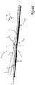
figure 9 est une vue de dessous d'une partie terminale d'un bras d'entrainement participant du système d'essuyage illustré sur lafigure 1 , - la
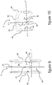
figure 10 est une vue en perspective de face de la partie terminale illustrée sur lafigure 9 , - la
figure 11 est une illustration schématique des étapes d'un procédé d'assemblage de l'adaptateur illustré sur lesfigures 3 à 8 sur une partie terminale d'un bras d'entraînement. - Sur les figures, les dénominations longitudinale, transversale, verticale, latérale, avant, arrière, gauche, droite, supérieure, inférieure, se réfèrent à l'orientation d'un balai d'essuyage 1 illustré sur la
figure 1 . Une direction longitudinale correspond à un axe longitudinal X selon lequel s'étend le balai d'essuyage 1 et/ou un adaptateur 2 de la présente invention. Une direction transversale correspond à celle d'un axe transversal Y qui est perpendiculaire à l'axe longitudinal X. Les dénominations gauche et droite s'apprécient par rapport à une position le long de l'axe transversal Y, de part et d'autre de l'axe longitudinal X. Une direction verticale, parallèle à celle d'un axe vertical Z, est perpendiculaire aux directions longitudinale et transversale susvisée. Les dénominations supérieure ou inférieure se rapportent à des orientations parallèles à l'axe vertical Z, la dénomination inférieure contenant le plan du pare-brise. Pour les directions longitudinales, les dénominations extérieure ou intérieure s'apprécient par rapport à un point de pivotement du balai d'essuyage 1 sur un bras d'entraînement 3 du balai d'essuyage 1, la dénomination intérieure correspondant à la partie où le bras d'entraînement 3 et un demi-balai s'étendent, la dénomination extérieure correspondant à la partie où l'autre demi-balai s'étend. - Les directions évoquées ci-dessus sont illustrées dans un repère orthonormé Oxyz représenté sur les figures. Dans ce repère, l'axe Ox représente la direction longitudinale, l'axe Oy représente la direction transversale, et l'axe Oz représente la direction verticale.
- Sur la
figure 1 , un véhicule automobile est couramment équipé d'un système d'essuyage 4 pour évacuer une eau et/ou des salissures présentes sur une surface vitrée, notamment une lunette arrière ou un pare-brise de véhicule automobile. Le système d'essuyage 4 comprend le bras d'entraînement 3 qui est apte à effectuer un mouvement de va-et-vient angulaire le long et au-dessus de la surface vitrée. - Le système d'essuyage 4 comprend aussi le balai d'essuyage 1 qui s'étend selon un axe principal, dit axe longitudinal X parallèle à l'axe Ox. Le balai d'essuyage 1 comprend au moins un déflecteur d'air 5 et une lame racleuse 6. Le déflecteur d'air 5 est prévu pour transformer une pression appliquée par un flux d'air circulant le long de la surface vitrée en une force d'appui du balai d'essuyage 1 contre la surface vitrée du véhicule automobile. La lame racleuse 6 est la pièce du balai d'essuyage 1 en contact direct avec la surface vitrée pour évacuer l'eau et/ou les salissures présentes sur cette dernière. Le déflecteur d'air 5 et la lame racleuse 6 forment un ensemble semi-rigide 7 qui est porté par un dispositif de connexion 8, interposé entre le bras d'entraînement 3 et l'ensemble semi-rigide 7.
- Le dispositif de connexion 8 assure une liaison mécanique entre une partie terminale 9 du bras d'entraînement 3 et le balai d'essuyage 1 et permet ainsi de séparer le balai d'essuyage 1 du bras d'entraînement 3, en vue d'un remplacement du balai d'essuyage 1. La présente invention vise notamment à proposer un adaptateur 2 qui est agencé pour faciliter une telle opération de remplacement, tout en sécurisant de manière efficace ladite liaison mécanique. Autrement dit, l'adaptateur 2 est particulièrement approprié pour un marché d'après-vente du balai d'essuyage 1.
- Dans sa généralité, le dispositif de connexion 8 de la présente invention comprend en tout et pour tout deux pièces, dont l'adaptateur 2 et un connecteur 10, visibles ensemble sur la
figure 2 , où l'adaptateur 2 de la présente invention est en position d'utilisation. Dans cette position d'utilisation, l'adaptateur 2 est rapporté dans la partie terminale 9 du bras d'entraînement 3, selon un procédé de l'invention décrit plus loin. - Le connecteur 10 est apte à porter le balai d'essuyage 1 et est monté en rotation sur l'adaptateur 2. L'adaptateur 2 est prévu pour être fixé à la partie terminale 9 du bras d'entraînement 3. Selon un mode de réalisation de l'invention, l'adaptateur 2 et le connecteur 10 sont réalisés par moulage d'un matériau synthétique, par exemple un matériau de la famille des Polyoxyméthylènes, connue sous l'acronyme POM, ou par moulage d'un mélange de matériaux polymères, par exemple un mélange de polymères de la famille des polycarbonates et de la famille des Acrylonitrile Butadiène Styrène, connue sous l'acronyme ABS. L'adaptateur 2 d'une part et le connecteur 10 d'autre part sont chacun d'un seul tenant. Autrement dit, l'adaptateur 2 d'une part et le connecteur 10 d'autre part sont monoblocs et ne peuvent être scindés en plusieurs morceaux qu'à partir d'une destruction de l'adaptateur 2 ou du connecteur 10. La partie terminale 9 est quant à elle par exemple réalisée par pliage d'un feuillard métallique, tel qu'une tôle en aluminium ou analogue ou bien par moulage d'une matière synthétique.
- En se reportant aux
figures 3 à 5 , l'adaptateur 2 est étendu selon l'axe longitudinal X et comporte une partie avant 11 et une partie arrière 12 qui sont articulées l'une à l'autre. La partie avant 11 et la partie arrière 12 sont successives l'une à l'autre le long de l'axe longitudinal X et sont donc alignées l'une après l'autre selon l'axe longitudinal X. La partie avant 11 et la partie arrière 12 sont mobiles l'une par rapport à l'autre autour d'un axe d'articulation A1 qui est orthogonal à l'axe longitudinal X, à l'axe vertical Z et parallèle à l'axe transversal Y. Autrement dit, la partie avant 11 et la partie arrière 12 sont montées en bascule l'une par rapport à l'autre autour de l'axe d'articulation A1. La partie avant 11 et la partie arrière 12 sont reliées l'une à l'autre par un moyen d'articulation 13 qui est interposé entre la partie avant 11 et la partie arrière 12 et qui forme un moyen de liaison entre la partie avant 11 et la partie arrière 12. - La partie avant 11 de l'adaptateur 2 comprend un corps 14 et une extrémité avant 15. Le corps 14 est la portion de la partie avant 11 qui est reliée à la partie arrière 12 par l'intermédiaire du moyen d'articulation 13. Le corps 14 est placé en position intermédiaire entre l'extrémité avant 15 et la partie arrière 12. L'extrémité avant 15, autrement appelé tête d'adaptateur, forme la portion extrême de la partie avant 11 située longitudinalement à l'opposé de la partie arrière 12. Autrement dit, le long de l'axe longitudinal X et depuis l'arrière de l'adaptateur 2 vers l'avant de celui-ci, sont successivement ménagés la partie arrière 12, le moyen d'articulation 13, le corps 14 et l'extrémité avant 15.
- La partie avant 11 forme une référence fixe à l'égard de la partie arrière 12, cette dernière étant la portion de l'adaptateur 2 qui tourne autour de la première partie 11 par le biais du moyen de rotation 13.
- La partie avant 11 et la partie arrière 12 présentent l'une et l'autre un profil transversal conformé en « U ». Autrement dit, selon une coupe transversale réalisée selon un plan de coupe parallèle au plan Oyz, la partie avant 11 et la partie arrière 12 comportent un profil transversal conformé en « U », ce qui confère à l'adaptateur 2 une structure évidée, avantageusement légère par économie de matière. En d'autres termes, la partie avant 11 comprend une paroi supérieure avant 11a qui forme la base du « U » et deux parois latérales avant 11b, 11b', notamment parallèles ou sensiblement parallèles entre elles et orthogonales, ou sensiblement orthogonales, à la paroi supérieure avant 11a, qui forment les branches du « U ».
- L'adaptateur 2 comprend encore un moyen de rotation 34 agencé pour relier l'adaptateur 2 au connecteur 10, tout en autorisant une rotation de l'un par rapport à l'autre. Ce moyen de rotation 34 autorise cette rotation autour de l'axe transversal Y. Le moyen de rotation peut être formé par une paire de torons qui émergent dans la structure évidée de l'adaptateur. Il peut également s'agir de paliers ménagés dans les parois latérales avant 11b, 11b'.
- De manière avantageuse, le moyen de rotation 34 est disposé sur l'adaptateur longitudinalement entre l'extrémité avant 15 et le moyen d'articulation 13.
- La partie arrière 12 comprend une paroi supérieure arrière 12a qui forme la base du « U » et deux parois latérales arrière 12b, 12b', parallèles ou sensiblement parallèles entre elles et orthogonales ou sensiblement orthogonales à la paroi supérieure arrière 12a, qui forment les branches de la forme en « U ».
- Plus particulièrement, la partie avant 11 comprend une paroi latérale avant gauche 11b et une paroi latérale avant droite 11b' tandis que la partie arrière 12 comprend une paroi latérale arrière gauche 12b et une paroi latérale arrière droite 12b'. De préférence, la paroi latérale avant gauche 11b et la paroi latérale arrière gauche 12b sont coplanaires ou sensiblement coplanaires. De préférence, la paroi latérale avant droite 11b' et la paroi latérale arrière droite 12b' sont aussi coplanaires ou sensiblement coplanaires.
- La paroi latérale avant gauche 11b et la paroi latérale arrière gauche 12b d'une part ainsi que la paroi latérale avant droite 11b' et la paroi latérale arrière droite 12b' d'autre part sont avantageusement reliées l'une à l'autre par le moyen d'articulation 13. Autrement dit, le moyen d'articulation 13 est interposé entre la paroi latérale avant gauche 11b et la paroi latérale arrière gauche 12b d'une part et entre la paroi latérale avant droite 11b' et la paroi latérale arrière droite 12b' d'autre part.
- Par ailleurs, la partie avant 11 comporte un bord arrière 11c qui est en vis-à-vis d'un bord avant 12c que comporte la partie arrière 12. Le moyen d'articulation 13 relie le bord arrière 11c et le bord avant 12c.
- Sur la
figure 3 , l'adaptateur 2 est représenté en position de repos tandis que sur lafigure 4 l'adaptateur 2 est représenté en position d'utilisation, c'est-à-dire tel que l'adaptateur 2 est illustré sur lafigure 2 . Lafigure 5 illustre enfin l'adaptateur 2 en position de montage. Autrement dit, sur lafigure 3 , l'adaptateur est représenté hors tout, tel qu'issu de moulage par exemple, tandis que sur lafigure 4 , l'adaptateur 2 est représenté comme si l'adaptateur 2 était rapporté sur la partie terminale 9 du bras d'entraînement 3, qui n'est pas représentée sur lafigure 4 pour conforter la lisibilité. Enfin, l'adaptateur 2 illustré sur lafigure 5 est dans une situation où un effort est exercé sur la partie arrière 12 en vue de monter ou démonter l'adaptateur 2 de la partie terminale 9. - Sur la
figure 3 , la paroi supérieure avant 11a et la paroi supérieure arrière 12a forment un premier angle α1 non-nul, tandis que sur lafigure 4 , la paroi supérieure avant 11a et la paroi supérieure arrière 12a sont coplanaires et forment un deuxième angle α2, qui dans le cas présent est sensiblement nul, suite à la mise en oeuvre du procédé de l'invention décrit ci-après. Selon un autre exemple de position d'utilisation, le deuxième angle α2 peut être différent de 0°, en étant positif ou négatif, étant entendu que le deuxième angle α2 est inférieur au premier angle α1. En position de montage, telle qu'illustrée à lafigure 5 , l'angle formé entre la paroi supérieure avant 11a et la paroi supérieure arrière 12a est inférieur à 0°, et en tout état de cause inférieur au deuxième angle α2. Les angles évoqués ci-dessus se mesurent entre un premier plan dans lequel s'étend la paroi supérieure avant 11a et un deuxième plan dans lequel s'étend la paroi supérieure arrière 12a. - De même sur la
figure 3 , le bord arrière 11c et le bord avant 12c forment un troisième angle α3 non-nul, préférentiellement compris entre 4° et 6°, préférentiellement égal à 5° tandis que, sur lafigure 4 , le bord arrière 11c et le bord avant 12c forment un quatrième angle α4 qui est strictement inférieur au troisième angle α3, ce quatrième angle α4 définissant la position d'utilisation. On notera qu'en position de montage telle que visible à lafigure 5 , le quatrième angle peut être nul, notamment quand le bord arrière 11c est en appui contre le bord avant 12c, de sorte à autoriser le franchissement d'une première paroi 95 de la partie terminale 9 par une dent 17 ménagé sur le bouton 16. Dans cette situation, une lumière débouchante 19 ménagée entre ces deux bords est fermée. La lumière 19 est qualifiée de débouchante en ce sens qu'elle sépare la paroi supérieure avant 11a de la paroi supérieure arrière 12a. La portion de lumière débouchante 19 ménagée entre les parois latérales avant et arrière s'évase en partant d'un bord inférieur 20 et en allant vers les parois supérieures 11a, 12a. - La paroi supérieure arrière 12a est pourvue d'un bouton 16 qui émerge au-dessus de la paroi supérieure arrière 12a. Autrement dit, le bouton 16 surplombe la paroi supérieure arrière 12a en étant placé au-dessus d'un plan formé par cette dernière. Le bouton 16 est conformé pour venir s'imbriquer à l'intérieur d'un orifice 90 que comporte la partie terminale 9 du bras d'entraînement 3, tel qu'illustré sur la
figure 2 . Le bouton 16 comporte une dent 17 qui surplombe et s'étend par-dessus la paroi supérieure arrière 12a. Une telle dent 17 forme un rebord issu du bouton 16 et qui s'étend longitudinalement vers l'arrière. Autrement dit, la dent 17 du bouton 16 forme une proéminence. Le bouton 16, en particulier sa dent 17, est agencé pour enserrer une épaisseur d'une première paroi 95 de la partie terminale 9 du bras d'entraînement 3. On notera que la longueur du bouton 16 augmenté de sa dent 17, mesurée le long de la direction longitudinale Ox, est inférieure à une longueur de l'orifice 90, mesurée selon la même direction. On permet ainsi au bouton 16 équipé de sa dent 17 de traverser l'orifice 90. - L'extrémité avant 15 est par exemple pourvue d'un crochet 18 qui surplombe au moins partiellement la paroi supérieure avant 11a du corps 14. Le crochet 18 est préférentiellement ménagé à égale distance de l'une et de l'autre des parois latérales avant 11b. Autrement dit, le crochet 18 est de préférence ménagé en un plan longitudinal médian de l'adaptateur 2.
- Les parois latérales avant 11b, 11b' et les parois latérales arrière 12b, 12b' sont séparées l'une de l'autre par la lumière débouchante 19 qui s'étend entre le moyen d'articulation 13 d'une part et la paroi supérieure avant 11a et la paroi supérieure arrière 12a de l'adaptateur 2 d'autre part. La lumière débouchante 19 permet un passage des parois latérales avant 11b et des parois latérales arrière 12b lors d'un mouvement de bascule 21 entre la partie avant 11 et la partie arrière 12 autour du moyen d'articulation 13. Autrement dit, lors du mouvement de bascule 21 de la partie avant 11 et/ou de la partie arrière 12 autour du moyen d'articulation 13, le bord arrière 11c de la partie avant 11 et le bord avant 12c de la partie arrière 12 sont aptes à se rapprocher l'un de l'autre ou à s'éloigner l'un de l'autre à partir d'un rétrécissement ou d'un élargissement de la lumière débouchante 19. La lumière débouchante 19 est par exemple conformée en « V » tel qu'illustrée sur les
figures 3 à 8 . - La partie arrière 12 est par exemple pourvue d'un moyen d'actionnement 23 dont un exemple est formé par une platine qui s'étend à l'intérieur d'un plan parallèle au plan Oxy lorsque l'adaptateur 2 est en position d'utilisation, à l'arrière de la partie arrière 12 et dans une direction longitudinale. Le moyen d'actionnement 23 forme un organe de préhension de la partie arrière 12 pour faire basculer cette dernière entre la position de repos de l'adaptateur 2 et la position de montage de l'adaptateur 2. Un tel moyen d'actionnement 23 permet d'assembler ou de séparer l'adaptateur 2 par rapport à la partie terminale 9 du bras d'entraînement 3.
- Sur la
figure 6 , l'extrémité avant 15 est profilé vers l'avant de l'adaptateur 2 de telle sorte que l'extrémité avant 15 présente une hauteur, prise entre une paroi supérieure 15a de l'extrémité avant 15 et le bord inférieur 20 de l'adaptateur 2 selon l'axe vertical Z, qui diminue depuis le corps 14 vers l'avant de l'extrémité avant 15. L'extrémité avant 15 forme un nez qui prolonge longitudinalement la partie terminale 9 de manière à le profiler. - En limite de la partie avant 11 et de l'extrémité avant 15, cette dernière présente une première hauteur verticale H1, prise entre la paroi supérieure 15a de cette extrémité avant 15 et le bord inférieur 20 de l'adaptateur 2 selon la direction Oz, qui est supérieure à une deuxième hauteur verticale H2 du corps 14, prise entre la paroi supérieure avant 11a et le bord inférieur 20 de l'adaptateur 2, selon la même direction Oz. En d'autres termes, l'extrémité avant 15 est plus haute que la première partie 11 de l'adaptateur 2, cette différence de hauteur étant par exemple égale à une épaisseur de la partie terminale 9 du bras d'entrainement 3. De manière complémentaire, l'extrémité avant 15 déborde également au-dessus de la première partie 11, en chevauchant longitudinalement celle-ci, au moins partiellement.
- En se reportant sur la
figure 7 , en limite de la partie avant 11 et de l'extrémité avant 15, cette dernière présente une première largeur transversale L1 prise entre des parois latérales avant 15b, 15b' de l'extrémité avant 15 selon l'axe transversal Y, qui est supérieure à une deuxième largeur transversale L2 du corps 14, prise entre la paroi latérale avant gauche 11b et la paroi latérale avant droite 11b', selon l'axe transversal Y. Il en résulte que l'extrémité avant 15 comporte une bordure 25, autrement appelée épaulement, qui émerge au-dessus de la paroi supérieure avant 11a du corps 14. En d'autres termes, l'extrémité avant 15 est plus large que la première partie 11 de l'adaptateur 2. De manière complémentaire, l'extrémité avant 15 déborde également de chaque côté de la première partie 11. Cette différence de largeur est par exemple égale à deux fois l'épaisseur de la paroi constitutive de la partie terminale 9 du bras d'entrainement 3. - La bordure 25 constitue une butée à l'encontre d'une arête avant 92 que comporte la partie terminale 9 du bras d'entraînement 3.
- La bordure 25 est équipée notamment du crochet 18. Le crochet 18 est indifféremment une excroissance de la paroi supérieure 15a de l'extrémité avant 15, tel que représenté sur les
figures 3 à 5 , ou bien un prolongement de cette paroi supérieure 15a à partir de la bordure 25, tel que représentée sur lesfigures 6 et7 . - La partie arrière 12 comprend au moins une rampe 31, et notamment deux rampes 31 qui sont ménagées verticalement et respectivement dans les parois latérales arrière 12b, 12b'. Chacune des rampes 31 s'étend dans un plan sensiblement parallèle au plan Oyz. Les rampes 31 délimitent chacune une gorge 33 ménagée dans paroi latérale gauche 12b et dans la paroi latérale droite 12b'.
- Sur la
figure 7 , le moyen d'articulation 13 est par exemple formé d'au moins un pontet 27, 27' qui relie la partie avant 11 et la partie arrière 12. Le moyen d'articulation 13 comprend notamment un pontet gauche 27 reliant la paroi latérale avant gauche 11b et la paroi latérale arrière gauche 12b et un pontet droit 27' reliant la paroi latérale avant droite 11b' et la paroi latérale arrière droite 12b'. Le moyen d'articulation 13 est simple à réaliser, notamment lors du moulage de l'adaptateur 2, une épaisseur E du moyen d'articulation 13 (visible sur lafigure 6 ) étant par exemple inférieure à 15% de la deuxième hauteur H2, l'épaisseur E étant prise selon l'axe vertical Z entre des bords supérieur et inférieur des pontets 27, 27'. Une telle épaisseur des pontets 27, 27' confère une flexibilité au moyen d'articulation 13 permettant l'articulation de la partie arrière 12 vis-à-vis de la partie avant 11. - Sur la
figure 8 , on constate la section en forme de « U » que peut prendre l'adaptateur 2 selon l'invention. Cette section en forme de « U » est formée par la paroi supérieure arrière 12a et les parois latérales arrière 12b, 12b', ainsi que par la paroi supérieure avant 11a et les parois latérales avant 11b, 11b'. Cette forme en « U » délimite un volume interne 32 agencé pour recevoir au moins en partie le connecteur 8 rendu solidaire du balai d'essuyage 1. - Ce volume interne peut également recevoir une languette 29 issue de moulage avec la partie arrière 12, par exemple avec la paroi supérieure arrière 12a de la partie arrière 12. La languette 29 est prévue pour venir en contact contre le connecteur 8 en position d'utilisation de l'adaptateur 2. Une telle languette 29 forme un dispositif de sécurisation de la liaison mécanique entre l'adaptateur 2 et la partie terminale 9 du bras d'entrainement 3. En effet, une fois l'adaptateur 2 installé dans la partie terminale 9, la languette 29 bloque le basculement de la partie arrière 12 par rapport à la partie avant 11, ce qui empêche le bouton 16 de sortir de l'orifice 90, par exemple lorsqu'il est exercé une traction sur le bras d'entrainement alors que le balai d'essuyage 1 est retenu sur le pare-brise par le gel, par exemple.
- Sur les
figures 9 et 10 , la partie terminale 9 du bras d'entraînement 3 est agencée en « U », vu dans une coupe transversale parallèle au plan Oyz. La partie terminale 9 comprend une première paroi 95 formant la base du « U » et deux deuxièmes parois 96 sensiblement parallèles et formant les branches du « U ». - La première paroi 95 est équipé de l'orifice 90, ce dernier étant centré latéralement sur la première paroi 95 de la partie terminale 9. La première paroi 95 et les deuxièmes parois 96 sont délimitées en partie avant par l'arête avant 92 qui présente un profil transversal en « U ».
- Les deuxièmes parois 96 comportent chacune une surface interne 97 qui délimite, avec la première paroi 95, un volume intérieur 99 de la partie terminale 9. Chaque surface interne 97 est pourvue d'un plot 98 qui émerge de la surface interne 97 vers le volume intérieur 99. Chaque plot 98 est par exemple agencé en un cylindre d'axe perpendiculaire à la surface interne 97. On notera que les deux plots 98 sont situés à égale distance de l'arête avant 92, de sorte qu'une droite passant par le centre de ces deux plots 98 est parallèle à l'axe transversal Y.
- L'orifice 90 et les plots 98 sont notamment ménagés à l'intérieur d'un plan transversal parallèle au plan Oxy, de telle sorte que l'orifice 90 surplombe verticalement les plots 98.
- Sur la
figure 11 , un procédé d'assemblage de l'adaptateur 2 avec une partie terminale 9 du bras d'entraînement 3 comprend une première étape 101 de mise en butée du crochet 18 de l'adaptateur 2 et de l'arête avant 92 de la première paroi 95 de la partie terminale 9. La première paroi 95 vient ainsi se loger entre le crochet 18 et la paroi supérieure avant 11a de la partie avant 11. - Selon une deuxième étape 102 du procédé, il est prévu une mise en rotation de l'adaptateur 2 sur la partie terminale 9 autour d'un deuxième axe de rotation A2 sensiblement parallèle à l'axe transversal Y et passant par un point de contact entre le crochet 18 et l'arête avant 92, tels que rapprochés l'un de l'autre au cours de la première étape 101. Cette rotation est opérée jusqu'à ce que le bouton 16 soit disposé au droit de l'orifice 90.
- A ce stade du procédé d'assemblage, le blocage de l'adaptateur 2 dans la partie terminale 9 peut être opéré selon deux étapes alternatives ou cumulatives.
- Selon l'une de ces alternatives, le procédé comprend une troisième étape 103 qui consiste à exercer un effort sur la partie arrière 12 de sorte à la rapprocher de la partie avant 11 par le biais du moyen d'articulation 13. Un tel effort peut être exercé en appliquant une pression manuelle sur la platine arrière 23. Cette troisième étape 103 conduit à une réduction du premier angle α1 (
figure 5 ) et à une réduction du troisième angle α3 (figure 5 ). La lumière débouchante 19 est alors fermée, ce qui conduit à rapprocher longitudinalement le bouton 16 de l'extrémité avant 15. Ce déplacement longitudinal du bouton 16 décale la dent 17 de sorte à lui permettre de pénétrer dans l'orifice 90. De manière synthétique, la troisième étape 103 consiste en un verrouillage manuel de l'adaptateur 2 dans la partie terminale 9. - Selon l'autre alternative, le procédé comprend une quatrième étape qui consiste en un verrouillage automatique de l'adaptateur 2 dans la partie terminale 9. En poursuivant la rotation débutée à la deuxième étape 102, les plots 98 pénètrent dans les gorges 33. Ce faisant, les plots 98 viennent en appui contre les rampes 31 de l'adaptateur 2, et coulissent contre ces dernières. Cette mise en appui provoque un effort qui génère un alignement de la paroi supérieure avant 11a avec la paroi supérieure arrière 12a, conduisant à une réduction du premier angle α1 (
figure 5 ) et à une réduction du troisième angle α3 (figure 5 ). La lumière débouchante 19 est alors fermée, ce qui conduit à rapprocher longitudinalement le bouton 16 de l'extrémité avant 15. Ce déplacement longitudinal du bouton 16 décale la dent 17 de sorte à lui permettre de pénétrer dans l'orifice 90. - Dans les deux cas présenté ci-dessus, il en résulte une mise sous contrainte de la partie arrière 2 qui tend ensuite à reprendre sa position de repos dans laquelle la paroi supérieure avant 11a et de la paroi supérieure arrière 12a forment le deuxième angle α2.
- Selon une cinquième étape 105, on poursuit la rotation opérée au cours de la deuxième étape 102 de sorte à ce que la dent 17 franchisse la première paroi 95 et se retrouve au-dessus de celle-ci. Une fois que la paroi supérieure arrière 12a est en appui contre une face interne de la première paroi 95 de la partie terminale 9, une mise en contact du bouton 16 contre le bord transversal avant 94 de l'orifice 90 est opérée, à partir d'une tendance de la partie arrière 12 à reprendre sa position de repos lorsque l'effort de flexion est interrompu. Il en résulte ainsi un verrouillage optimisé de l'adaptateur 2 dans la partie terminale 9 et une interdiction d'un déverrouillage inopiné de l'adaptateur 2 rapporté sur la partie terminale 9 du bras d'entraînement 3, notamment lors de l'utilisation du système d'essuyage 4 mis en mouvement le long de la surface vitrée.
- L'invention permet de solidariser ainsi simplement un balai d'essuyage sur une partie terminale de bras telle qu'illustré dans le présent document. L'adaptateur seul, ou le balai d'essuyage comprenant un tel adaptateur forme un article de commerce vendu dans les réseaux après-vente de commerce de pièce automobile.
Claims (16)
- Adaptateur (2) destiné à équiper une partie terminale (9) d'un bras d'entraînement (3), l'adaptateur (2) comprenant au moins une partie avant (11) dont au moins une section est agencée en « U » et au moins une partie arrière (12) dont au moins une section est agencée en « U », dans lequel la partie avant (11) et la partie arrière (12) sont articulées l'une à l'autre par l'intermédiaire d'un moyen d'articulation (13), caractérisé en ce que l'adaptateur (2) est pourvu d'un moyen d'actionnement (23) de la partie arrière (12).
- Adaptateur (2) selon la revendication 1, dans lequel la section agencée en « U » de la partie avant (11) est délimitée par une paroi supérieure avant (11a), une paroi latérale avant gauche (11b) et une paroi latérale avant droite (11b'), tandis que la section agencée en « U » de la partie arrière (12) est délimitée par une paroi supérieure arrière (12a), une paroi latérale arrière gauche (12b) et une paroi latérale arrière droite (12b').
- Adaptateur (2) selon la revendication 1 ou 2, dans lequel le moyen d'articulation (13) est interposé entre la paroi latérale avant gauche (11b) et la paroi latérale arrière gauche (12b) et dans lequel le moyen d'articulation (13) est interposé entre la paroi latérale avant droite (11b') et la paroi latérale arrière droite (12b').
- Adaptateur (2) selon l'une quelconque des revendications précédentes, dans lequel la partie avant (11) et la partie arrière (12) sont alignées selon un axe longitudinal (X) de l'adaptateur (2).
- Adaptateur (2) selon l'une quelconque des revendications précédentes, dans lequel la partie avant (11) comprend un corps (14) et une extrémité avant (15), le corps (14) étant relié à la partie arrière (12) par l'intermédiaire du moyen d'articulation (13).
- Adaptateur (2) selon la revendication 5, dans lequel l'extrémité avant (15) et le corps (14) sont délimités par une bordure (25) qui surplombe le corps (14).
- Adaptateur (2) selon la revendication 6, dans lequel la bordure (25) est équipée d'au moins un crochet (18).
- Adaptateur (2) selon l'une quelconque des revendications précédentes, comprenant un moyen de rotation (34) configuré pour relier l'adaptateur (2) à un connecteur (10).
- Adaptateur (2) selon l'une quelconque des revendications précédentes prise en combinaison avec la revendication 2, dans lequel la paroi supérieure arrière (12a) est équipée d'un bouton (16) pourvu d'une dent (17).
- Adaptateur (2) selon l'une quelconque des revendications précédentes prise en combinaison avec la revendication 2, dans lequel au moins une paroi latérale arrière (12b, 12b') est équipée d'une gorge (33) délimitée au moins par une rampe (31).
- Dispositif de connexion (8) formé d'un connecteur (10) et d'un adaptateur (9) selon l'une quelconque des revendications précédentes.
- Bras d'entraînement (3) comprenant au moins une partie terminale (9) conformée en « U » et délimitée par une première paroi (95) et par deux deuxièmes parois (96) délimitant un volume intérieur (99) dans lequel est reçu un adaptateur (2) selon l'une quelconque des revendications 1 à 10 ou un dispositif de connexion (8) selon la revendication précédente.
- Bras d'entraînement (3) selon la revendication précédente, dans lequel la première paroi (95) est pourvue d'un orifice (90) de réception d'un bouton (16) pourvu d'une dent (17), l'orifice (90) comprenant un bord transversal avant (94) contre lequel le bouton (16) prend appui, la dent (17) s'étendant au-dessus de la première paroi (95).
- Système d'essuyage comprenant un bras d'entraînement (3), un connecteur (10) solidaire d'un balai d'essuyage (1) et un adaptateur (2) selon l'une quelconque des revendications 1 à 10 reliant à rotation le connecteur (10) au bras d'entraînement (3).
- Procédé d'assemblage d'un adaptateur (2) selon l'une quelconque des revendications 1 à 10 avec une partie terminale (9) d'un bras d'entraînement (3), dans lequel le procédé d'assemblage comprend :- une première étape (101) de mise en contact d'une bordure (25) de l'adaptateur (2) contre une arête avant (92) d'une première paroi (95) de la partie terminale (9),- une deuxième étape (102) qui consiste en une rotation de l'adaptateur (2) vis-à-vis de la partie terminale (9) autour du contact entre la bordure (25) et l'arête avant (92) opéré au cours de la première étape (101),- une cinquième étape (105) où une dent (17) d'un bouton (16) de l'adaptateur (2) franchit la première paroi (95) et s'étend au-dessus de celle-ci.
- Procédé d'assemblage selon la revendication précédente, au cours duquel est prévu entre la deuxième et la cinquième étapes, alternativement ou cumulativement :- une troisième étape (103) qui consiste en un verrouillage manuel de l'adaptateur (2) dans la partie terminale (9),- une quatrième étape (104) qui consiste en un verrouillage automatique de l'adaptateur (2) dans la partie terminale (9).
Applications Claiming Priority (1)
| Application Number | Priority Date | Filing Date | Title |
|---|---|---|---|
| FR1659353A FR3056511B1 (fr) | 2016-09-29 | 2016-09-29 | Adaptateur constitutif d'un systeme d'essuyage |
Publications (2)
| Publication Number | Publication Date |
|---|---|
| EP3300967A1 EP3300967A1 (fr) | 2018-04-04 |
| EP3300967B1 true EP3300967B1 (fr) | 2019-05-15 |
Family
ID=57396700
Family Applications (1)
| Application Number | Title | Priority Date | Filing Date |
|---|---|---|---|
| EP17188098.2A Active EP3300967B1 (fr) | 2016-09-29 | 2017-08-28 | Adaptateur constitutif d'un systeme d'essuyage |
Country Status (5)
| Country | Link |
|---|---|
| US (1) | US10829093B2 (fr) |
| EP (1) | EP3300967B1 (fr) |
| CN (1) | CN107878405A (fr) |
| FR (1) | FR3056511B1 (fr) |
| MX (1) | MX2017012483A (fr) |
Families Citing this family (10)
| Publication number | Priority date | Publication date | Assignee | Title |
|---|---|---|---|---|
| US20130219649A1 (en) | 2012-02-24 | 2013-08-29 | Pylon Manufacturing Corp. | Wiper blade |
| USD842213S1 (en) * | 2016-01-26 | 2019-03-05 | Cap Corporation | Adapter of windscreen wiper |
| US11040705B2 (en) | 2016-05-19 | 2021-06-22 | Pylon Manufacturing Corp. | Windshield wiper connector |
| CA3070567A1 (fr) | 2017-07-28 | 2019-01-31 | Pylon Manufacturing Corp. | Raccord et ensemble d'essuie-glace |
| US11465590B2 (en) | 2017-07-28 | 2022-10-11 | Pylon Manufacturing Corporation | Windshield wiper blade assembly |
| US11027705B2 (en) * | 2017-11-03 | 2021-06-08 | Trico Products Corporation | Windscreen wiper device |
| JP6996442B2 (ja) | 2018-07-17 | 2022-01-17 | 株式会社デンソー | 車両用ワイパ |
| KR102338807B1 (ko) * | 2019-12-02 | 2021-12-15 | 주식회사 캐프 | 와이퍼 블레이드 조립용 어댑터, 와이퍼 블레이드 조립체 및 와이퍼 장치 |
| CN113428112B (zh) * | 2020-11-09 | 2023-02-28 | 厦门富可汽车配件有限公司 | 一种适配器及雨刷 |
| CN113830029B (zh) * | 2021-01-06 | 2023-02-28 | 厦门富可汽车配件有限公司 | 一种适配器及雨刷 |
Family Cites Families (10)
| Publication number | Priority date | Publication date | Assignee | Title |
|---|---|---|---|---|
| IT1032673B (it) * | 1975-04-15 | 1979-06-20 | Arman Sas Di Dario Arman Ec | Perfezionamento relativo al supporto delle lame tergenti di spazzole negli impianti tergivetro a bordo di autoveicoli in genere |
| US20020174504A1 (en) * | 2001-05-22 | 2002-11-28 | Adm 21 Co., Ltd | Adapter for windshield wiper arms |
| DE112011103091B4 (de) * | 2010-09-15 | 2020-10-01 | Trico Products Corporation | Universelles Kopplungselement für eine Windschutzscheibenwischeranordnung vom Typ Balkenblatt |
| FR2978406B1 (fr) * | 2011-07-27 | 2014-11-21 | Valeo Systemes Dessuyage | Adaptateur d'essuie-glace a position de securite |
| US9073518B2 (en) | 2011-09-15 | 2015-07-07 | Asmo Co., Ltd. | Vehicle wiper |
| KR101350276B1 (ko) * | 2011-11-09 | 2014-01-13 | 케이씨더블류 주식회사 | 차량용 와이퍼 커넥터 |
| CN104125899B (zh) * | 2011-12-29 | 2016-08-31 | 费德罗-莫格尔公司 | 挡风玻璃的雨刮器装置 |
| FR3026074B1 (fr) * | 2014-09-23 | 2016-11-18 | Valeo Systemes Dessuyage | Adaptateur de liaison d'un bras d'entrainement d'un balai d'essuie-glace a un connecteur relie audit balai d'essuie-glace |
| WO2016061461A1 (fr) * | 2014-10-17 | 2016-04-21 | Federal-Mogul Motorparts Corporation | Dispositif d'essuie-glace |
| US10046739B2 (en) * | 2014-12-23 | 2018-08-14 | Trico Products Corporation | Wiper adapter and wiper assembly incorporating the same |
-
2016
- 2016-09-29 FR FR1659353A patent/FR3056511B1/fr active Active
-
2017
- 2017-08-28 EP EP17188098.2A patent/EP3300967B1/fr active Active
- 2017-09-28 US US15/718,891 patent/US10829093B2/en active Active
- 2017-09-28 CN CN201710897880.0A patent/CN107878405A/zh active Pending
- 2017-09-28 MX MX2017012483A patent/MX2017012483A/es unknown
Non-Patent Citations (1)
| Title |
|---|
| None * |
Also Published As
| Publication number | Publication date |
|---|---|
| FR3056511A1 (fr) | 2018-03-30 |
| EP3300967A1 (fr) | 2018-04-04 |
| US10829093B2 (en) | 2020-11-10 |
| FR3056511B1 (fr) | 2022-01-14 |
| CN107878405A (zh) | 2018-04-06 |
| MX2017012483A (es) | 2018-09-26 |
| US20180086312A1 (en) | 2018-03-29 |
Similar Documents
| Publication | Publication Date | Title |
|---|---|---|
| EP3300967B1 (fr) | Adaptateur constitutif d'un systeme d'essuyage | |
| EP3300968B1 (fr) | Adaptateur constitutif d'un systeme d essuyage | |
| FR3050158A1 (fr) | Systeme d’essuyage d’un pare-brise de vehicule | |
| EP3170709B1 (fr) | Adaptateur, connecteur et ensemble forme d'un tel connecteur et d'un tel adaptateur pour un balai d'essuyage | |
| EP3184379B1 (fr) | Capuchon et bras d'entrainement pour un dispositif d'essuyage pour vehicule automobile | |
| FR3059961A1 (fr) | Adaptateur pour balai d'essuie glace | |
| EP3395630B1 (fr) | Adaptateur constitutif d'un systeme d'essuyage | |
| FR3059960B1 (fr) | Adaptateur pour balai d'essuyage | |
| EP3461701B1 (fr) | Dispositif de connexion d'un balai d'essuyage a un bras d'entrainemant pour vehicule | |
| EP3170708B1 (fr) | Ensemble forme d'un bras d'entrainement et d'un connecteur pour essuie-glace | |
| FR3056514A1 (fr) | Systeme de protection anti-perte d'un balai d'essuyage pour vehicule automobile | |
| EP3170707B1 (fr) | Capuchon equipant un connecteur pour un balai d'essuyage d'un vehicule automobile | |
| EP3512743B1 (fr) | Adaptateur pour la connexion d'un balai d'essuyage a un bras d'entrainement d'un systeme d'essuyage pour vehicule automobile | |
| FR3044618A1 (fr) | Adaptateur pour un bras d'entrainement d'un systeme d'essuyage | |
| WO2022254038A1 (fr) | Dispositif de connexion et ensemble d'essuyage pour véhicule automobile | |
| FR3100772A1 (fr) | aménagement de parechoc pour véhicule automobile | |
| EP3112228B1 (fr) | Organe pour un système de connexion d'un balai d'essuyage à un bras d'essuie-glace | |
| FR3056513A1 (fr) | Dispositif de connexion entre un balai d'essuyage et une partie terminale d'un bras d'entrainement | |
| WO2023030973A1 (fr) | Adaptateur d'un système d'essuyage | |
| FR3049916A1 (fr) | Capuchon equipant un connecteur pour un balai d'essuyage d'un vehicule automobile | |
| EP3205537A1 (fr) | Adaptateur constitutif d'un systeme d essuyage | |
| FR3044617A1 (fr) | Adaptateur pour un bras d'entrainement d'un systeme d'essuyage | |
| FR3064961A1 (fr) | Bras d'entrainement et ensemble pour un dispositif d'essuyage pour vehicule automobile | |
| EP4360926A1 (fr) | Dispositif d'accès comprenant une porte en élytre | |
| FR3121895A1 (fr) | Capot pour ensemble d'essuyage pour véhicule automobile |
Legal Events
| Date | Code | Title | Description |
|---|---|---|---|
| PUAI | Public reference made under article 153(3) epc to a published international application that has entered the european phase |
Free format text: ORIGINAL CODE: 0009012 |
|
| STAA | Information on the status of an ep patent application or granted ep patent |
Free format text: STATUS: REQUEST FOR EXAMINATION WAS MADE |
|
| 17P | Request for examination filed |
Effective date: 20170828 |
|
| AK | Designated contracting states |
Kind code of ref document: A1 Designated state(s): AL AT BE BG CH CY CZ DE DK EE ES FI FR GB GR HR HU IE IS IT LI LT LU LV MC MK MT NL NO PL PT RO RS SE SI SK SM TR |
|
| AX | Request for extension of the european patent |
Extension state: BA ME |
|
| GRAP | Despatch of communication of intention to grant a patent |
Free format text: ORIGINAL CODE: EPIDOSNIGR1 |
|
| STAA | Information on the status of an ep patent application or granted ep patent |
Free format text: STATUS: GRANT OF PATENT IS INTENDED |
|
| RIC1 | Information provided on ipc code assigned before grant |
Ipc: B60S 1/40 20060101AFI20181025BHEP |
|
| INTG | Intention to grant announced |
Effective date: 20181129 |
|
| RIN1 | Information on inventor provided before grant (corrected) |
Inventor name: GAUCHER, VINCENT Inventor name: HOUSSAT, STEPHANE Inventor name: JOMARD, OLIVIER |
|
| GRAS | Grant fee paid |
Free format text: ORIGINAL CODE: EPIDOSNIGR3 |
|
| GRAA | (expected) grant |
Free format text: ORIGINAL CODE: 0009210 |
|
| STAA | Information on the status of an ep patent application or granted ep patent |
Free format text: STATUS: THE PATENT HAS BEEN GRANTED |
|
| AK | Designated contracting states |
Kind code of ref document: B1 Designated state(s): AL AT BE BG CH CY CZ DE DK EE ES FI FR GB GR HR HU IE IS IT LI LT LU LV MC MK MT NL NO PL PT RO RS SE SI SK SM TR |
|
| REG | Reference to a national code |
Ref country code: CH Ref legal event code: EP |
|
| REG | Reference to a national code |
Ref country code: DE Ref legal event code: R096 Ref document number: 602017003898 Country of ref document: DE |
|
| REG | Reference to a national code |
Ref country code: IE Ref legal event code: FG4D Free format text: LANGUAGE OF EP DOCUMENT: FRENCH |
|
| REG | Reference to a national code |
Ref country code: NL Ref legal event code: MP Effective date: 20190515 |
|
| REG | Reference to a national code |
Ref country code: LT Ref legal event code: MG4D |
|
| PG25 | Lapsed in a contracting state [announced via postgrant information from national office to epo] |
Ref country code: SE Free format text: LAPSE BECAUSE OF FAILURE TO SUBMIT A TRANSLATION OF THE DESCRIPTION OR TO PAY THE FEE WITHIN THE PRESCRIBED TIME-LIMIT Effective date: 20190515 Ref country code: NL Free format text: LAPSE BECAUSE OF FAILURE TO SUBMIT A TRANSLATION OF THE DESCRIPTION OR TO PAY THE FEE WITHIN THE PRESCRIBED TIME-LIMIT Effective date: 20190515 Ref country code: HR Free format text: LAPSE BECAUSE OF FAILURE TO SUBMIT A TRANSLATION OF THE DESCRIPTION OR TO PAY THE FEE WITHIN THE PRESCRIBED TIME-LIMIT Effective date: 20190515 Ref country code: LT Free format text: LAPSE BECAUSE OF FAILURE TO SUBMIT A TRANSLATION OF THE DESCRIPTION OR TO PAY THE FEE WITHIN THE PRESCRIBED TIME-LIMIT Effective date: 20190515 Ref country code: ES Free format text: LAPSE BECAUSE OF FAILURE TO SUBMIT A TRANSLATION OF THE DESCRIPTION OR TO PAY THE FEE WITHIN THE PRESCRIBED TIME-LIMIT Effective date: 20190515 Ref country code: FI Free format text: LAPSE BECAUSE OF FAILURE TO SUBMIT A TRANSLATION OF THE DESCRIPTION OR TO PAY THE FEE WITHIN THE PRESCRIBED TIME-LIMIT Effective date: 20190515 Ref country code: NO Free format text: LAPSE BECAUSE OF FAILURE TO SUBMIT A TRANSLATION OF THE DESCRIPTION OR TO PAY THE FEE WITHIN THE PRESCRIBED TIME-LIMIT Effective date: 20190815 Ref country code: PT Free format text: LAPSE BECAUSE OF FAILURE TO SUBMIT A TRANSLATION OF THE DESCRIPTION OR TO PAY THE FEE WITHIN THE PRESCRIBED TIME-LIMIT Effective date: 20190915 Ref country code: AL Free format text: LAPSE BECAUSE OF FAILURE TO SUBMIT A TRANSLATION OF THE DESCRIPTION OR TO PAY THE FEE WITHIN THE PRESCRIBED TIME-LIMIT Effective date: 20190515 |
|
| PG25 | Lapsed in a contracting state [announced via postgrant information from national office to epo] |
Ref country code: GR Free format text: LAPSE BECAUSE OF FAILURE TO SUBMIT A TRANSLATION OF THE DESCRIPTION OR TO PAY THE FEE WITHIN THE PRESCRIBED TIME-LIMIT Effective date: 20190816 Ref country code: LV Free format text: LAPSE BECAUSE OF FAILURE TO SUBMIT A TRANSLATION OF THE DESCRIPTION OR TO PAY THE FEE WITHIN THE PRESCRIBED TIME-LIMIT Effective date: 20190515 Ref country code: RS Free format text: LAPSE BECAUSE OF FAILURE TO SUBMIT A TRANSLATION OF THE DESCRIPTION OR TO PAY THE FEE WITHIN THE PRESCRIBED TIME-LIMIT Effective date: 20190515 Ref country code: BG Free format text: LAPSE BECAUSE OF FAILURE TO SUBMIT A TRANSLATION OF THE DESCRIPTION OR TO PAY THE FEE WITHIN THE PRESCRIBED TIME-LIMIT Effective date: 20190815 |
|
| REG | Reference to a national code |
Ref country code: AT Ref legal event code: MK05 Ref document number: 1133061 Country of ref document: AT Kind code of ref document: T Effective date: 20190515 |
|
| PG25 | Lapsed in a contracting state [announced via postgrant information from national office to epo] |
Ref country code: AT Free format text: LAPSE BECAUSE OF FAILURE TO SUBMIT A TRANSLATION OF THE DESCRIPTION OR TO PAY THE FEE WITHIN THE PRESCRIBED TIME-LIMIT Effective date: 20190515 Ref country code: EE Free format text: LAPSE BECAUSE OF FAILURE TO SUBMIT A TRANSLATION OF THE DESCRIPTION OR TO PAY THE FEE WITHIN THE PRESCRIBED TIME-LIMIT Effective date: 20190515 Ref country code: CZ Free format text: LAPSE BECAUSE OF FAILURE TO SUBMIT A TRANSLATION OF THE DESCRIPTION OR TO PAY THE FEE WITHIN THE PRESCRIBED TIME-LIMIT Effective date: 20190515 Ref country code: SK Free format text: LAPSE BECAUSE OF FAILURE TO SUBMIT A TRANSLATION OF THE DESCRIPTION OR TO PAY THE FEE WITHIN THE PRESCRIBED TIME-LIMIT Effective date: 20190515 Ref country code: DK Free format text: LAPSE BECAUSE OF FAILURE TO SUBMIT A TRANSLATION OF THE DESCRIPTION OR TO PAY THE FEE WITHIN THE PRESCRIBED TIME-LIMIT Effective date: 20190515 |
|
| REG | Reference to a national code |
Ref country code: DE Ref legal event code: R097 Ref document number: 602017003898 Country of ref document: DE |
|
| PG25 | Lapsed in a contracting state [announced via postgrant information from national office to epo] |
Ref country code: SM Free format text: LAPSE BECAUSE OF FAILURE TO SUBMIT A TRANSLATION OF THE DESCRIPTION OR TO PAY THE FEE WITHIN THE PRESCRIBED TIME-LIMIT Effective date: 20190515 Ref country code: IT Free format text: LAPSE BECAUSE OF FAILURE TO SUBMIT A TRANSLATION OF THE DESCRIPTION OR TO PAY THE FEE WITHIN THE PRESCRIBED TIME-LIMIT Effective date: 20190515 |
|
| PLBE | No opposition filed within time limit |
Free format text: ORIGINAL CODE: 0009261 |
|
| STAA | Information on the status of an ep patent application or granted ep patent |
Free format text: STATUS: NO OPPOSITION FILED WITHIN TIME LIMIT |
|
| PG25 | Lapsed in a contracting state [announced via postgrant information from national office to epo] |
Ref country code: TR Free format text: LAPSE BECAUSE OF FAILURE TO SUBMIT A TRANSLATION OF THE DESCRIPTION OR TO PAY THE FEE WITHIN THE PRESCRIBED TIME-LIMIT Effective date: 20190515 |
|
| 26N | No opposition filed |
Effective date: 20200218 |
|
| PG25 | Lapsed in a contracting state [announced via postgrant information from national office to epo] |
Ref country code: PL Free format text: LAPSE BECAUSE OF FAILURE TO SUBMIT A TRANSLATION OF THE DESCRIPTION OR TO PAY THE FEE WITHIN THE PRESCRIBED TIME-LIMIT Effective date: 20190515 |
|
| PG25 | Lapsed in a contracting state [announced via postgrant information from national office to epo] |
Ref country code: MC Free format text: LAPSE BECAUSE OF FAILURE TO SUBMIT A TRANSLATION OF THE DESCRIPTION OR TO PAY THE FEE WITHIN THE PRESCRIBED TIME-LIMIT Effective date: 20190515 Ref country code: SI Free format text: LAPSE BECAUSE OF FAILURE TO SUBMIT A TRANSLATION OF THE DESCRIPTION OR TO PAY THE FEE WITHIN THE PRESCRIBED TIME-LIMIT Effective date: 20190515 Ref country code: LU Free format text: LAPSE BECAUSE OF NON-PAYMENT OF DUE FEES Effective date: 20190828 |
|
| PG25 | Lapsed in a contracting state [announced via postgrant information from national office to epo] |
Ref country code: IE Free format text: LAPSE BECAUSE OF NON-PAYMENT OF DUE FEES Effective date: 20190828 |
|
| PGFP | Annual fee paid to national office [announced via postgrant information from national office to epo] |
Ref country code: BE Payment date: 20200819 Year of fee payment: 4 |
|
| REG | Reference to a national code |
Ref country code: CH Ref legal event code: PL |
|
| PG25 | Lapsed in a contracting state [announced via postgrant information from national office to epo] |
Ref country code: CH Free format text: LAPSE BECAUSE OF NON-PAYMENT OF DUE FEES Effective date: 20200831 Ref country code: RO Free format text: LAPSE BECAUSE OF FAILURE TO SUBMIT A TRANSLATION OF THE DESCRIPTION OR TO PAY THE FEE WITHIN THE PRESCRIBED TIME-LIMIT Effective date: 20190515 Ref country code: LI Free format text: LAPSE BECAUSE OF NON-PAYMENT OF DUE FEES Effective date: 20200831 |
|
| PG25 | Lapsed in a contracting state [announced via postgrant information from national office to epo] |
Ref country code: CY Free format text: LAPSE BECAUSE OF FAILURE TO SUBMIT A TRANSLATION OF THE DESCRIPTION OR TO PAY THE FEE WITHIN THE PRESCRIBED TIME-LIMIT Effective date: 20190515 |
|
| PG25 | Lapsed in a contracting state [announced via postgrant information from national office to epo] |
Ref country code: IS Free format text: LAPSE BECAUSE OF FAILURE TO SUBMIT A TRANSLATION OF THE DESCRIPTION OR TO PAY THE FEE WITHIN THE PRESCRIBED TIME-LIMIT Effective date: 20190915 |
|
| PG25 | Lapsed in a contracting state [announced via postgrant information from national office to epo] |
Ref country code: HU Free format text: LAPSE BECAUSE OF FAILURE TO SUBMIT A TRANSLATION OF THE DESCRIPTION OR TO PAY THE FEE WITHIN THE PRESCRIBED TIME-LIMIT; INVALID AB INITIO Effective date: 20170828 Ref country code: MT Free format text: LAPSE BECAUSE OF FAILURE TO SUBMIT A TRANSLATION OF THE DESCRIPTION OR TO PAY THE FEE WITHIN THE PRESCRIBED TIME-LIMIT Effective date: 20190515 |
|
| REG | Reference to a national code |
Ref country code: BE Ref legal event code: MM Effective date: 20210831 |
|
| GBPC | Gb: european patent ceased through non-payment of renewal fee |
Effective date: 20210828 |
|
| PG25 | Lapsed in a contracting state [announced via postgrant information from national office to epo] |
Ref country code: MK Free format text: LAPSE BECAUSE OF FAILURE TO SUBMIT A TRANSLATION OF THE DESCRIPTION OR TO PAY THE FEE WITHIN THE PRESCRIBED TIME-LIMIT Effective date: 20190515 |
|
| PG25 | Lapsed in a contracting state [announced via postgrant information from national office to epo] |
Ref country code: GB Free format text: LAPSE BECAUSE OF NON-PAYMENT OF DUE FEES Effective date: 20210828 Ref country code: BE Free format text: LAPSE BECAUSE OF NON-PAYMENT OF DUE FEES Effective date: 20210831 |
|
| P01 | Opt-out of the competence of the unified patent court (upc) registered |
Effective date: 20230528 |
|
| PGFP | Annual fee paid to national office [announced via postgrant information from national office to epo] |
Ref country code: FR Payment date: 20230828 Year of fee payment: 7 Ref country code: DE Payment date: 20230808 Year of fee payment: 7 |