EP4234852B1 - Schlüssel und schliessvorrichtung - Google Patents
Schlüssel und schliessvorrichtung Download PDFInfo
- Publication number
- EP4234852B1 EP4234852B1 EP23176724.5A EP23176724A EP4234852B1 EP 4234852 B1 EP4234852 B1 EP 4234852B1 EP 23176724 A EP23176724 A EP 23176724A EP 4234852 B1 EP4234852 B1 EP 4234852B1
- Authority
- EP
- European Patent Office
- Prior art keywords
- key
- cam
- longitudinal direction
- head
- transition
- Prior art date
- Legal status (The legal status is an assumption and is not a legal conclusion. Google has not performed a legal analysis and makes no representation as to the accuracy of the status listed.)
- Active
Links
Images




Classifications
-
- E—FIXED CONSTRUCTIONS
- E05—LOCKS; KEYS; WINDOW OR DOOR FITTINGS; SAFES
- E05B—LOCKS; ACCESSORIES THEREFOR; HANDCUFFS
- E05B19/00—Keys; Accessories therefor
- E05B19/0017—Key profiles
-
- E—FIXED CONSTRUCTIONS
- E05—LOCKS; KEYS; WINDOW OR DOOR FITTINGS; SAFES
- E05B—LOCKS; ACCESSORIES THEREFOR; HANDCUFFS
- E05B19/00—Keys; Accessories therefor
- E05B19/0017—Key profiles
- E05B19/0041—Key profiles characterized by the cross-section of the key blade in a plane perpendicular to the longitudinal axis of the key
- E05B19/0052—Rectangular flat keys
-
- E—FIXED CONSTRUCTIONS
- E05—LOCKS; KEYS; WINDOW OR DOOR FITTINGS; SAFES
- E05B—LOCKS; ACCESSORIES THEREFOR; HANDCUFFS
- E05B27/00—Cylinder locks or other locks with tumbler pins or balls that are set by pushing the key in
- E05B27/0042—Cylinder locks or other locks with tumbler pins or balls that are set by pushing the key in with additional key identifying function, e.g. with use of additional key operated rotor-blocking elements, not of split pin tumbler type
Definitions
- the present invention relates to a key for a locking cylinder, wherein the key shaft extends in a longitudinal direction from a key head to a key tip of the key, wherein the key shaft has two key broad side surfaces, wherein the key further has a cam. Furthermore, the present invention relates to a locking device with a key and a locking cylinder.
- Such keys and locking cylinders are known, for example, from the publication EP 1 593 800 B1 known.
- the publication EP 1 593 800 B1 relates to a locking device consisting of a key and a locking cylinder, wherein a cylinder core mounted in a cylinder housing has a key channel for inserting the key shaft of the appropriate key, which key shaft is able to fit into the key channel to displace protruding locking pins in such a way that the cylinder core is rotatable, wherein the key shaft has an insert piece which interacts with a supplementary locking part mounted in a bore of the cylinder core, wherein the insert piece has a shaft and a head, wherein the shaft is inserted into an opening in the key shaft and the head interacts with a supplementary part.
- the head of such an insert serves as a projection or cam that is interrogated in the cylinder core, for example by means of the associated additional locking part, as a security feature.
- Every time the key is used to open the corresponding locking cylinder mechanical forces act on the insert.
- the insert is mechanically stressed every time the key is used. After a certain number of uses of the key, the insert can become loose, which can cause the insert to fall out of the hole or at least make it more difficult to interrogate the insert in the cylinder core.
- the publication WO 2020/249462 A1 shows a key for a cylinder lock, comprising at least one coded side surface running along the longitudinal direction of the key, wherein at least one coding for interrogation in the cylinder lock is provided on the side surface, wherein the coding comprises a first interrogation surface running in the longitudinal direction of the key and a second interrogation surface running in the longitudinal direction of the key, wherein the interrogation surfaces are arranged offset from one another in a transverse direction of the key, and wherein the interrogation surfaces are arranged offset from one another in the longitudinal direction, and in cross-section each have the shape of a continuous and preferably periodic curve.
- the publication FR 2 451 983 A1 shows a system consisting of cylinder locks and the associated flat keys.
- Locking elements are mounted in the holes of the rotary cylinders, which are pushed outwards by additional longitudinal ribs of the key so that a housing pin cannot fall into the holes and lock them.
- the lower additional longitudinal ribs are missing, and instead the classifying notch at the scanning point of the locking elements is left out, so that the plug pin assigned to this notch protrudes further upwards and pushes the lower locking elements outwards with its thickened shaft.
- the subordinate keys can Consequently, they cannot be converted directly into master keys, as they have less material than these.
- the additional longitudinal ribs are provided with depressions or interruptions that are sensed by locking pins in front of the locking elements. These locking pins prevent the lock from being picked from the outside by operating the locking elements.
- the publication EP 2 290 178 A2 shows a flat key, in particular a reversible key for cylinder locks, with a copy-protected flat profile body which has a predetermined structured cross-sectional area. Furthermore, there are grooves and/or countersunk sections for coding on the longitudinal wide and/or longitudinal narrow sides of the flat profile body, with the grooves extending parallel to one another and forming the profile of the key.
- the flat profile body has at least one rib on its longitudinal wide side which runs parallel to the grooves and protrudes over the respective surface of the profile body, with an additional coding option being created over the length of the rib and/or its position relative to selected countersunk sections.
- a key for a locking device having a key shaft, the key shaft extending in a longitudinal direction from a key head to a key tip of the key, the key shaft having two key broad side surfaces, the key further comprising a cam that protrudes from one of the key broad side surfaces, the cam being formed integrally with the key shaft, the cam having a head region, the head region being convex in a first direction that runs perpendicular to the longitudinal direction and parallel to the key broad side surfaces, the cam having a key head-side transition region and a key tip-side transition region, wherein the head region is arranged in the longitudinal direction between the key head-side and the key tip-side transition region, wherein the key head-side and the key tip-side transition region are designed such that the cam has a smooth transition to the key broad side surface in the longitudinal direction, wherein the cam has two lateral transition regions, wherein the head region is arranged in the first direction between the two lateral transition regions, wherein the two lateral transition regions
- the head region preferably extends in the longitudinal direction.
- the head region of the cam is the region of the cam with the greatest height.
- the head region is in particular the region that is used for querying in the locking cylinder.
- the head region can in particular be designed such that a cam control pin of the associated locking device rests against the head region when the key is fully inserted into the locking cylinder and is arranged in a release position.
- the head region has a length in the longitudinal direction.
- the length of the head region can be 1 mm to 9 mm, preferably 3 mm to 7 mm, in particular 5.1 mm.
- the head region has a width in the first direction.
- the width of the head region can be 0.5 mm to 2 mm, preferably 8 mm to 1.5 mm, in particular 1.1 mm.
- the transition area on the key tip side is arranged between the head area and the key broad side surface.
- the transition area on the key tip side describes the transition of the cam to the key broad side surface on the side of the cam facing the key tip.
- the transition area on the key head side is also arranged between the head area and the key broad side surface.
- the transition area on the key head side describes the transition of the cam to the key broad side surface on the side of the cam facing the key head.
- the transition areas on the key head side and the key tip side are designed such that the cam has a smooth transition to the key broad side surface in the longitudinal direction.
- the transition areas on the key tip side and the key head side can each have a convex section and a concave section.
- the convex section borders the head area
- the concave section adjoins the key broadside surface.
- the transition between the convex and concave sections can run parallel to the second direction or inclined to the second direction.
- the transition from the concave region to the key broadside surface is preferably smooth.
- the convex and concave sections preferably have the same radius of curvature.
- the key head-side transition region is preferably longer in the longitudinal direction than the key tip-side transition region.
- the lateral transition regions describe the transition of the cam to the key broad side surface on both sides of the cam in the first direction.
- the lateral transition regions are designed such that the cam has a smooth transition to the key broad side surface on both sides in the first direction.
- the lateral transition regions can be straight.
- the lateral transition regions can have a constant inclination with respect to the second direction.
- the inclination with respect to the second direction can be 0° to 45°, preferably 20° to 35°.
- the inclinations of the two lateral transition regions can be different.
- one lateral transition region can be inclined by 20° and the other by 35°.
- the key shaft of the key extends between the key head and the key tip of the key. This extension defines a longitudinal direction of the key from key head to key tip.
- the key shaft can have a rectangular or essentially rectangular cross-sectional profile along the longitudinal direction.
- the two longer sides of this rectangle are referred to as the key broad side surfaces.
- the two shorter sides of the rectangle in cross section are referred to below as the key narrow side surfaces.
- the two key broad side surfaces are thus arranged perpendicular to the longitudinal direction on opposite sides of the key shaft.
- the key shaft has a length in the longitudinal direction.
- the length of the key shaft can be 20 mm to 70 mm, preferably 30 mm to 50 mm, in particular 43 mm.
- a first direction runs perpendicular to the longitudinal direction and parallel to each key broadside surface.
- the first direction can also be the key broadside direction. or width direction.
- the key shaft has a width in the first direction.
- the width of the key shaft can be 4 mm to 20 mm, preferably 6 mm to 12 mm, in particular 8.9 mm.
- a second direction runs perpendicular to the longitudinal direction and perpendicular to each key broad side surface.
- the second direction can also be called the key narrow side direction or height direction.
- the key shaft has a height (also called thickness) in the second direction.
- the height of the key shaft can be 1 mm to 10 mm, preferably 2 mm to 5 mm, in particular 2.4 mm.
- the longitudinal direction, the first direction and the second direction are perpendicular to each
- the cam is arranged on at least one of the key broad side surfaces.
- a cam can also be arranged on each key broad side surface, for example if the key is designed as a reversible key.
- the cam is a projection that protrudes from the key broad side surface in the second direction. In other words, the cam rises from the corresponding key broad side surface in the second direction.
- Each key broad side surface can have a basic profile contour.
- the basic profile contour of each key broad side surface can have a plane, whereby one or more recesses (such as holes, grooves, cutouts, etc.) can be formed starting from the plane, which serve as security features of the key and can be interrogated in a locking cylinder. These recesses thus extend in the second direction from the plane inwards.
- the cam thus protrudes in particular on the flat side, i.e. from the plane, of the basic profile contour in the second direction.
- the cam is formed in one piece with the key shaft.
- the cam is formed integrally with the key shaft.
- a die-casting process an extrusion process or a machining process (for example a milling process) can be used.
- the cam has a length in the longitudinal direction.
- the length can be 2 mm to 10 mm, preferably 4 mm to 8 mm, in particular 6.3 mm.
- the cam has a width in the first direction.
- the width can be 0.8 mm to 3 mm, preferably 1.2 mm to 2 mm, in particular 1.5 mm.
- the cam has a height in the second direction.
- the height can be 0.1 mm to 2 mm, preferably 0.2 mm to 1 mm, more preferably 0.3 mm to 0.7 mm, in particular 0.48 mm.
- a locking device is provided with a key according to the first aspect and a locking cylinder, the locking cylinder having a housing and a cylinder core, the locking cylinder having one or more locking devices, each locking device being movable between a locking state and a release state and locking a rotational movement of the cylinder core relative to the housing in the locking state and releasing it in the release state, the cam being associated with one of the locking devices.
- the cylinder core has an essentially cylindrical shape. A radial direction and an axial direction are defined according to this cylindrical shape.
- the key channel has an opening at one axial end of the cylinder core through which the key can be inserted or inserted into the key channel.
- the key is inserted into the key channel of the cylinder core in an insertion direction and removed from the key channel of the cylinder core in the opposite direction to the insertion direction.
- the insertion direction corresponds to the axial direction.
- the cam of the key is interrogated with the associated locking device.
- the cam interacts with the associated locking device in such a way that the locking device cannot block a rotational movement when the key is fully inserted. In other words, the locking device is in the release state when the key is fully inserted.
- the locking device can enter the locked state if the key is not fully inserted or if an incorrect key is used, in particular a key without a cam or without a matching cam.
- the locking device can be designed in such a way that the locking device has the locking state as its basic state, i.e. in the state without an inserted key, and can only be transferred to the release state by completely inserting the correct key, i.e. the key with the matching cam. In other words, the rotary movement is only released when the key with the matching cam has been completely inserted.
- the locking device can also be designed in such a way that the locking device initially enables the rotational movement and only switches to the locking state after the cylinder core has been rotated by a certain angle, for example 135° or 225°, if the key does not have the appropriate cam.
- the locking device has the release state as its basic state. If a key with the appropriate cam is used, the locking device remains in the release state even when the cylinder core is rotated. If, however, a key is used that does not have the appropriate cam, the locking device is switched to the locking state after the cylinder core has been rotated by the certain angle. In this case, the incorrect key can no longer be removed.
- the key Because the cam is made in one piece with the key shaft, the key has a high level of mechanical stability in the area of the cam. This prevents the position of the cam from changing, the cam from becoming deformed, or the cam from falling off the key shaft after a large number of uses of the key.
- the cam extends in the longitudinal direction.
- the cam is preferably elongated.
- the length of the cam can be greater than the width of the cam.
- the cam has a length in the longitudinal direction, wherein the length of the cam is 5-25%, preferably 8-20%, more preferably 10-15%, in particular 12%, of the length of the key shaft.
- the cam therefore extends in the longitudinal direction only over a relatively small area of the key's broad side surface.
- a transition of the cam to the key broadside surface is smooth.
- the term “smooth” means that the transition is continuous and has no edge or bend.
- the slope or gradient of the broad side surface of the key and the slope or gradient of the cam at the transition are the same. This further improves the mechanical stability of the key in the area of the cam.
- the cam cannot be curved too much in the transition areas. For example, a radius of curvature in these areas can be greater than 0.1 mm. This also further improves the mechanical stability.
- the head region is flat in the longitudinal direction.
- the height of the cam remains the same or substantially the same along the longitudinal direction in the head region.
- the cam can be rounded in the head region.
- the curvature of the head region in the first direction can have a radius of curvature of 1 mm to 5 mm, preferably 2 mm to 3 mm, in particular 2.4 mm.
- the key tip-side transition region can have a length.
- the length of the key tip-side transition region can be 0.2 mm to 1.5 mm, preferably 0.3 mm to 1 mm, in particular 0.4 mm.
- the transition between the convex and the concave section of the key tip-side transition region is preferably inclined relative to the second direction.
- the inclination can be 5° to 45°, preferably 12° to 30°, in particular 20°.
- the radii of curvature of the convex and concave sections of the key tip-side transition region are preferably the same and are 0.1 mm to 0.75 mm, preferably 0.15 mm to 0.5 mm, in particular 0.2 mm.
- the key head-side transition region can have a length.
- the length of the key head-side transition region can be 0.2 mm to 1.5 mm, preferably 0.4 mm to 1.2 mm, in particular 0.8 mm.
- the transition between the convex and the concave section of the key head-side transition region is preferably parallel to the second direction.
- the radii of curvature of the convex and concave sections of the key head-side transition region are preferably the same and are 0.1 mm to 0.75 mm, preferably 0.2 mm to 0.6 mm, in particular 0.4 mm.
- the cam is arranged in the longitudinal direction on the key broad side surface in the middle or on the key head side.
- the cam is spaced from the key tip.
- the cam is arranged closer to the key head than to the key tip.
- the distance to the key tip can be 10 mm to 30 mm in the longitudinal direction, preferably 15 mm to 25 mm, in particular 22 mm.
- the key shaft has a key stop, wherein the cam is arranged in the longitudinal direction on or near the key stop.
- the key stop forms a stop for the locking cylinder.
- the key shaft can only be inserted or plugged into the key channel of the cylinder core up to the key stop.
- the key stop thus defines an insertion area of the key in the longitudinal direction.
- the insertion area is the area of the key shaft that is arranged in the key channel when the key is fully inserted into the key channel.
- the cam extends in the longitudinal direction from the key stop in the direction of the key tip.
- an end of the cam on the key head side can be arranged closer to the key head than the key stop, for example by 0.5 mm. In other words, the cam can extend further towards the key head than the insertion area of the key.
- the cam is arranged at a distance from the lateral edges of the key shaft in the first direction.
- the cam is spaced apart from the narrow sides of the key shaft.
- the cam can be arranged centrally or offset from the center in the first direction with respect to the key shaft.
- the key broad side surface has a plurality of longitudinal grooves, each longitudinal groove running parallel to the longitudinal direction (16), the cam being arranged on an elevation between two of the plurality of longitudinal grooves.
- the longitudinal grooves form recesses in the basic profile contour of the key broad side surfaces in the second direction. Between two longitudinal grooves, the basic profile contour then has a raised area.
- the raised area is preferably flat in the longitudinal direction.
- the raised area only rises to a maximum of the level of the basic profile contour of the key broad side surface.
- the cam is arranged on such a raised area.
- the cam thus increases the raised area in the second direction over the key broad side surfaces (in particular over the level of the basic profile contour of the key broad side surfaces). In other words, the cam sits on such an elevation.
- the elevation has a width in the first direction.
- the width of the elevation can be 1.5 mm to 8 mm, preferably 2 mm to 5 mm, in particular 3.11 mm.
- the elevation extends to the key tip.
- the elevation can have a convex profile in the longitudinal direction.
- the longitudinal grooves can be correspondingly concavely curved.
- the radius of curvature of the curvature of the elevation can be 1 mm to 5 mm, preferably 2 mm to 3 mm, in particular 2.4 mm.
- the curvature of the elevation in the first direction has the same radius of curvature as the curvature of the head region of the cam.
- the centers of curvature of these two curvatures can be offset from one another in the first direction.
- the offset can be, for example, 0.1 to 0.5 mm, preferably 0.2 mm to 0.3 mm, in particular 0.25 mm.
- a transition from the cam to the elevation is smooth.
- the transition from the cam to the elevation is continuous and has no edge or kink.
- the cam and the elevation have the same slope or inclination at the transition.
- the concave areas of the key head side and the key tip side transition area enable a smooth transition in the longitudinal direction to the flat area of the elevation.
- the elevation slopes, preferably straight, into the two longitudinal grooves.
- the elevation has a slope or inclination on each of the sides. At the transition, the slope or inclination corresponds to the slope or inclination of the corresponding lateral transition area. In this way, the mechanical stability is further improved.
- the locking device has a cam control pin, wherein the cam control pin is mounted in the cylinder core so as to be movable in the radial direction, wherein the cam control pin is movable in the radial direction between a locking position and a release position, wherein Inserting the key allows the cam control pin to be moved from the locked position to the released position by the cam.
- the cylinder core preferably has a radial bore that extends to the keyway.
- the cam control pin is arranged in the radial bore and is mounted therein so that it can move in the radial direction between the locking position and the release position.
- the cam control pin is arranged in the release position, the locking lock is in the release state.
- the cam control pin is arranged in the locking position, the locking lock can be moved into the locking state.
- the locking device has a housing pin, wherein the housing pin is mounted in the housing so as to be movable in the radial direction, wherein the housing pin is prestressed inwards in the radial direction, wherein, when the cam control pin and the housing pin are arranged radially aligned, the cam control pin and the housing pin interact in such a way that the housing pin blocks the rotational movement of the cylinder core relative to the housing in the locking position of the cam control pin and releases it in the release position of the cam control pin, in particular wherein the locking device is in the locking state when the housing pin blocks the rotational movement of the cylinder core relative to the housing.
- the housing preferably has a radial bore that extends radially outward from the cylinder core.
- the housing pin is arranged in the radial bore and is mounted therein so as to be movable in the radial direction.
- the housing pin is preloaded inwards in the radial direction by means of a spring element. If the cam control pin and the housing pin are not arranged in radial alignment, the locking device is in the release state. If the cam control pin and the housing pin are arranged in radial alignment, the cam control pin and the housing pin can work together to transfer the locking device between the release state and the locking state.
- the housing pin is designed such that it can be guided into the radial bore of the cylinder core in which the cam control pin is arranged, if the cam control pin and the housing pin are arranged in radial alignment. If the housing pin is partially in the radial bore of the cylinder core, the rotational movement of the cylinder core relative to the housing is blocked. The locking device is then in the locked state. If the cam control pin is in the locked position (i.e. if the cam control pin is not offset radially outwards by the matching cam), the locking device is moved to the locked state or the locking device remains in the locked state if the cam control pin and the housing pin are arranged in radial alignment. If the cam control pin is in the release position (i.e.
- the locking device is moved to the released state or the locking device remains in the released state if the cam control pin and the housing pin are arranged in radial alignment.
- the movement of the locking device from the locked state to the released state or the holding of the locking device in the released state is carried out by the cam, which pushes the cam control pin into the release position and holds it there.
- the cam prevents the housing pin from penetrating the radial bore of the cylinder core.
- the movement of the locking device from the release state to the locking state or the holding of the locking device in the locking state is carried out by the preload force, which presses the housing pin radially inwards.
- the preload force causes the housing pin to be pressed radially inwards into the radial bore of the cylinder core.
- the key channel has a longitudinal groove which is associated with the cam, wherein the longitudinal groove extends at least as far as the cam control pin.
- the longitudinal groove extends at least from the opening of the key channel at the axial end of the cylinder core to the cam control pin.
- the length of the longitudinal groove in the axial direction of the cylinder core can be as long as the length of the cam in the longitudinal direction of the key.
- the longitudinal groove preferably extends to the radial bore for the cam control pin.
- the cam control pin In the locking position, the cam control pin is partially arranged in the longitudinal groove, in particular with its radially inner end. The radially inner end can be rounded.
- a cross-sectional contour of the longitudinal groove is complementary to a circumferential surface of the cam.
- a peripheral surface contour of the cam in particular a size of the cam, can also be queried.
- the outer cross-sectional contour can then serve as a further security feature, which can be queried using the key channel.
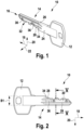
- the Figures 1 to 3 show an embodiment of a key 10.
- the key 10 has a key head 12, which is also called a key handle.
- the key head 12 is used to manually grip the key 10.
- a key shaft 14 extends from the key head 12.
- Various security features are arranged on the key shaft 14, which are checked when the key 10 is inserted into a corresponding locking device. If the check is positive, the locking device can be moved from a locked state to a released state.
- the key shaft 14 extends along a longitudinal direction 18 from the key head 12 to a key tip 16 of the key 10.
- the key shaft 14 has a rectangular or substantially rectangular cross-sectional profile.
- the two longer sides of this rectangle are referred to as the key broad side surfaces 24.
- the two shorter sides of the rectangle in cross section are referred to below as the key narrow side surfaces 26.
- the key broad side surfaces 24 and the key narrow side surfaces 26 are each arranged opposite one another.
- a first direction 20 runs perpendicular to the longitudinal direction 18 and parallel to each key broadside surface 24.
- a second direction 22 runs perpendicular to the longitudinal direction 18 and perpendicular to each key broadside surface 24.
- the longitudinal direction 18, the first direction 20 and the second direction 22 are perpendicular to each other in pairs.
- the directions 18, 20, 22 thus form a Cartesian coordinate system.
- the key shaft 14 has a length L1 in the longitudinal direction 18.
- the length L1 can be 20 mm to 70 mm, preferably 30 mm to 50 mm, in particular 43 mm.
- the key shaft 14 has a width B1 in the first direction 20.
- the width B1 can be 4 mm to 20 mm, preferably 6 mm to 12 mm, in particular 8.9 mm.
- the key shaft 14 has a height H1 in the second direction 22.
- the height H1 can be 1 mm to 10 mm, preferably 2 mm to 5 mm, in particular 2.4 mm.
- Each key broadside surface can have a basic profile contour.
- the basic profile contour of each key broadside surface can have a plane, wherein one or more recesses (such as holes, grooves, cutouts, etc.) can be formed starting from the plane.
- each key broadside surface can have a plurality of longitudinal grooves 28.
- the key broadside surface 24 has two longitudinal grooves 28.
- a raised area 30 is arranged between the two longitudinal grooves 28.
- the raised area 30 also extends in the longitudinal direction 18.
- the longitudinal grooves 28 and the raised area 30 can extend to the key tip 16. The raised area 30 becomes wider towards the longitudinal grooves 28.
- the key shaft 14 can further have a key bit 32 which is formed on a key narrow side surface 26.
- the key shaft 14 can also have a key stop 34.
- the key stop 34 serves as a stop for a lock cylinder when the key 10 is inserted into the lock cylinder. In other words, the key can only be inserted into the lock cylinder from the key tip 16 to the key stop 34.
- the key stop 34 thus defines an insertion area of the key shaft 14 in the longitudinal direction 18, which can be inserted into the lock cylinder. The security features of the key 10 to be interrogated are arranged in this insertion area.
- the key 10 further comprises a cam 36.
- the cam is arranged on one of the key broad side surfaces 24.
- the key 10 can also comprise a cam 36 on each key broad side surface 24 and/or comprise a plurality of cams on one key broad side surface 24.
- the cam 36 protrudes in the second direction 22 from the key broad side surface 24.
- the cam 36 is formed in one piece with the key shaft 14. In other words, the cam is formed integrally with the key shaft 14.
- the transitions of the Cam to the key broadside surface 24 are smooth in the longitudinal direction 18 and in the first direction 20.
- the cam 36 is arranged in the longitudinal direction 18 on the key broad side surface 24 in the middle or on the key head side.
- the cam 36 is spaced from the key tip 16.
- the cam 36 can be arranged closer to the key head 12 than to the key tip 16.
- the cam 36 can also be equally spaced from the key tip 16 and the key head 12.
- the distance to the key tip 16 in the longitudinal direction 18 can be, for example, 10 mm to 30 mm, preferably 15 mm to 25 mm, in particular 22 mm.
- the cam 36 is arranged in the longitudinal direction 18 on the key stop 34.
- the cam 36 extends in the longitudinal direction 18 from the key stop 34 in the direction of the key tip 16.
- An end of the cam 36 on the key head side is arranged closer (for example by 0.5 mm) to the key head 12 than the key stop 34.
- the cam 36 is arranged at a distance from the lateral edges of the key shaft 14 in the first direction 20.
- the cam 36 is thus at a distance from the narrow side surfaces in the first direction.
- the cam 36 can be arranged on the elevation 30.
- the cam 36 has a length L2 in the longitudinal direction 18.
- the length L2 can be 2 mm to 10 mm, preferably 4 mm to 8 mm, in particular 6.3 mm.
- the cam 36 has a width B2 in the first direction 20.
- the width B2 can be 0.8 mm to 3 mm, preferably 1.2 mm to 2 mm, in particular 1.5 mm.
- the cam 36 has a height H2 in the second direction 22.
- the height H2 can be 0.1 mm to 2 mm, preferably 0.2 mm to 1 mm, more preferably 0.3 mm to 0.7 mm, in particular 0.48 mm.
- the cam 36 extends in the longitudinal direction 18.
- the cam 36 can be elongated.
- the length L2 of the cam 36 can be greater than the width B2 of the cam 36.
- the cam has a head region 38, a key tip-side transition region 40, a key head-side transition region 42 and two lateral transition regions 44, 46.
- the head region 38 is arranged in the longitudinal direction 18 between the key tip-side transition region 40 and the key head-side transition region 42.
- the head region 38 is arranged in the first direction 20 between the two lateral transition regions 44, 46.
- the transition regions 40-46 describe the transitions of the cam 36 from the head region 38 to the key broad side surface 24 in the longitudinal direction 18 and the first direction 20.
- the transition regions 40-46 are in particular designed such that the cam 36 has smooth transitions to the key broad side surface 24 in the longitudinal direction 18 and in the first direction 20 (i.e. on all sides of the cam 36).
- the head region 38 has a length in the longitudinal direction 18.
- the length of the head region 38 can be 1 mm to 9 mm, preferably 3 mm to 7 mm, in particular 5.1 mm.
- the head region 38 has a width in the first direction 20.
- the width of the head region 38 can be 0.5 mm to 2 mm, preferably 8 mm to 1.5 mm, in particular 1.1 mm.
- the head region 38 is flat in the longitudinal direction 18.
- the head region 38 is convex in the first direction 20, in particular rounded.
- the curvature of the head region 38 in the first direction 20 can have a radius of curvature of 1 mm to 5 mm, preferably 2 mm to 3 mm, in particular 2.4 mm.
- the key tip-side transition region 40 has a convex and a concave section in the longitudinal direction 18.
- the convex section borders on the head region 38.
- the concave section borders on the key broad side surface 24.
- the transition from the concave region to the key broad side surface 24 is smooth.
- the transition from the convex section to the head region 38 is preferably also smooth.
- the transition between the convex and the concave section of the key tip-side transition region 40 is preferably inclined relative to the second direction 20.
- the inclination can be 5° to 45°, preferably 12° to 30°, in particular 20°.
- the radii of curvature of the convex and concave sections of the key tip-side transition region are preferably the same and are 0.1 mm to 0.75 mm, preferably 0.15 mm to 0.5 mm, in particular 0.2 mm.
- the key head-side transition region 42 has a convex and a concave section in the longitudinal direction 18.
- the convex section borders on the head region 38.
- the concave section borders on the key broad side surface 24.
- the transition from the concave region to the key broad side surface 24 is smooth.
- the transition from the convex section to the head region 38 is preferably also smooth.
- the transition between the convex and the concave section of the key head-side transition region 42 is preferably parallel to the second direction.
- the radii of curvature of the convex and concave sections of the key head-side transition region 42 are preferably the same and are 0.1 mm to 0.75 mm, preferably 0.2 mm to 0.6 mm, in particular 0.4 mm.
- the lateral transition regions 44, 46 are designed such that the cam 36 has a smooth transition to the key broad side surface 24 on both sides in the first direction 20.
- the lateral transition regions 44, 46 are straight, i.e. without curvature.
- the lateral transition regions 44, 46 have a constant inclination with respect to the second direction 22.
- the inclination with respect to the second direction can be 0° to 45°, preferably 20° to 35°.
- the first lateral transition region 44 can have an inclination of 20° with respect to the second direction 22 and the second lateral transition region 46 can have an inclination of 35° with respect to the second direction 22.
- the elevation 30 In the area in the longitudinal direction 18 between the cam 36 and the key tip 16, the elevation 30 has a convex profile in the first direction 20 and a flat profile in the longitudinal direction 18.
- the two longitudinal grooves 28 on the two sides of the elevation 30 have a concave profile in the first direction 20.
- the radius of curvature of the curvature of the elevation 30 can be 1 mm to 5 mm, preferably 2 mm to 3 mm, in particular 2.4 mm.
- the curvature of the elevation 30 in the first direction has the same radius of curvature as the curvature of the head region 38 of the cam 36.
- the curvature of the elevation 30 runs around a curvature center Z1 and the curvature of the head region 38 runs around a curvature center Z2.
- the curvature centers Z1 and Z2 are offset from one another in the second direction according to the height H2 of the cam 36.
- the curvature centers Z1 and Z2 can also be offset from one another in the first direction 20.
- the offset in the first direction can be, for example, 0.1 to 0.5 mm, preferably 0.2 mm to 0.3 mm, in particular 0.25 mm.
- the cam 36 and the elevation 30 are designed at the transitions in the longitudinal direction 18 and the first direction 20 so that these transitions are smooth.
- the cam 36 and the elevation 30 have the same slope or inclination at the transitions.
- the concave areas of the key head side and the key tip side transition areas 40, 42 enable a smooth transition in the longitudinal direction 18 to the flat area of the elevation 30.
- the elevation 30 slopes straight down into the two longitudinal grooves.
- the elevation has a slope or inclination on each of these sides. At the transition, the slope or inclination corresponds to the slope or inclination of the corresponding lateral transition area 44, 46.
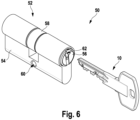
- Fig.6 shows an embodiment of a locking device 50.
- the locking device has the key 10 as described above in connection with the Figures 1 to 5
- the locking device 50 has a locking cylinder 52.
- the locking cylinder 52 is a profile cylinder. However, it can also be a different shape, for example a round cylinder or oval cylinder.
- the locking cylinder 52 has a housing 54, a cylinder core 56 and a locking nose 58.
- the cylinder core 52 has a substantially cylindrical shape. A radial direction, an axial direction and a circumferential direction are defined in accordance with this cylindrical shape.
- the housing 54 has a cylindrical bore. The cylindrical bore extends from a first end to a second end of the housing 54.
- the cylinder core 56 is arranged in the cylindrical bore and is mounted so as to be rotatable in the circumferential direction.
- the cylinder core 56 is mounted in the housing 54, for example by means of a locking ring.
- the housing 54 also has a recess for the locking lug 58.
- the locking lug 58 is coupled to the cylinder core 56 and can be rotated together with it.
- the housing 54 is provided, for example, with a mounting bore 60 or threaded bore in order to be able to screw the locking cylinder 52 into a door.
- the housing 54 and the cylinder core 56 can basically have a plurality of bores in which locking devices, in particular pin tumblers, are guided in order to query various security features of the key 10.
- the cylinder core 56 has a key channel 62.
- the key channel 62 has an opening at one axial end of the cylinder core 56 through which the key can be inserted or plugged into the key channel 62.
- the key channel 62 extends in the axial direction.
- the key 10 is inserted into this key channel 62.
- all locking devices are moved to a position that allows the cylinder core 56 to rotate relative to the housing 54. This is referred to as the release state. If the key 10 is not fully inserted into the key channel 86 or completely pulled out of it, the cylinder core 56 cannot rotate relative to the housing 54. This is referred to as the locking state.
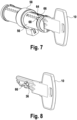
- the locking cylinder 52 is shown without the housing 54.
- the locking cylinder has a locking device 64.
- the locking device 64 is assigned to the cam 36.
- the locking device 66 cooperates with the cam 36 in such a way that by completely By inserting the key 10, the locking device 64 can be transferred into the release state by the cam 36 or is held in this state.
- the locking device 64 has a cam control pin 66.
- the cam control pin can also be referred to as a core pin.
- the cam control pin 66 is arranged in a radial bore 68 of the cylinder core.
- the radial bore extends in the radial direction from a radially outer edge of the cylinder core 56 to the key channel 62.
- the cam control pin 66 is mounted in the radial bore 68 so as to be movable in the radial direction.
- a radially inner end of the cam control pin 66 is rounded.
- Fig.9 the cylinder core 56 is shown without key 10.
- Fig.10 the cylinder core 56 is shown with the key 10 inserted.
- the key channel 62 of the cylinder core 56 has a longitudinal groove 70.
- the longitudinal groove 70 extends in the axial direction up to the radial bore 68.
- the longitudinal groove 70 is assigned to the cam 36.
- a cross-sectional contour of the longitudinal groove 70 is complementary to a peripheral surface of the cam 36.
- the longitudinal groove 70 extends in the axial direction from the opening of the key channel 62 at the axial end of the cylinder core 56 up to the radial bore 68, that is to say up to the cam control pin 66.
- the cam 36 is guided in the longitudinal groove 70 up to the cam control pin 66 when the key 10 is inserted.
- the cam control pin 66 is movable in the radial bore 68 in the radial direction between a locking position 78 and a release position 74.
- the cam control pin 66 In the locking position 78, the cam control pin 66 is arranged further inward in the radial direction than in the release position 74.
- the cam control pin In the locking position 78, the cam control pin extends 66 partially, in particular with its radially inner end, into the longitudinal groove 70. In the release position 74, the cam control pin 66 does not extend into the longitudinal groove 70.
- the locking device 64 may further comprise a housing pin 80 and a spring element 82 in the housing 54.
- the housing pin 80 is radially movable and is biased inward in the radial direction via the spring element 82.
- the cam control pin 66 and the housing pin 80 may cooperate to transfer the locking device 64 between the release state 72 and the locking state 76.
- the lock cylinder 52 is constructed such that the housing pin 80 and the cam control pin 66 are arranged in alignment when the cylinder core 56 has been rotated by a certain angle (for example by 135° in one direction or by 225° in the other direction) after the key 10 has been fully inserted.
- the lock cylinder 52 can also be constructed such that the housing pin 80 and the cam control pin 66 are arranged in alignment without the cylinder core 56 being rotated.
- the locking lock 66 is in the locking state 76 when the cam control pin 66 is arranged in the locking position 78 and the housing pin 80 and the cam control pin 66 are arranged in alignment.
- the housing pin 80 extends from the housing 54 into the radial bore 68 and thereby blocks rotation of the cylinder core 56.
- the locking device is in the release state 72 when the cam control pin 66 is arranged in the release position 74 or when the housing pin 80 and the cam control pin 66 are not aligned.
- the release position 74 the housing pin does not extend into the radial bore 68 and the cam control pin 66 only extends to a maximum of the radially outer edge of the cylinder core 56, whereby rotation of the cylinder core 56 is released.
- the cam control pin When the key is removed from the lock cylinder, the cam control pin is pushed back into the locking position 78 by the pre-tensioning force of the spring element. If the key 10 is therefore only partially or not at all inserted into the key channel 62, the cam control pin 66 is arranged in the locking position 78. This is shown in the Figures 12 and 14 shown.
- Fig. 15 The example shows the case in which the key is either not fully inserted or a key is used that does not have a suitable cam.
- the cam control pin 66 is then not moved into the release position 74, but is arranged in the locking position 78.
- the housing pin 80 is partially pressed into the radial bore 68 by the preload force of the spring element 82 and thereby blocks the rotary movement of the cylinder core 56 relative to the housing 54. Accordingly, the locking device 64 is in the locking state 76.
- Fig. 16 The example shows the case in which the key is completely inserted and the key also has the matching cam 36.
- the cam control pin 66 is thus moved by the cam into the release position 74.
- the housing pin 80 is therefore not arranged in the radial bore 68 and therefore does not block the Rotational movement of the cylinder core 56 relative to the housing 54. Accordingly, the locking device 64 is in the release state 72.
Landscapes
- Lock And Its Accessories (AREA)
Priority Applications (1)
| Application Number | Priority Date | Filing Date | Title |
|---|---|---|---|
| HRP20241494TT HRP20241494T1 (hr) | 2022-06-09 | 2023-06-01 | Ključ i uređaj za zaključavanje |
Applications Claiming Priority (1)
| Application Number | Priority Date | Filing Date | Title |
|---|---|---|---|
| DE102022114503.4A DE102022114503A1 (de) | 2022-06-09 | 2022-06-09 | Schlüssel und Schließvorrichtung |
Publications (3)
| Publication Number | Publication Date |
|---|---|
| EP4234852A1 EP4234852A1 (de) | 2023-08-30 |
| EP4234852B1 true EP4234852B1 (de) | 2024-08-07 |
| EP4234852C0 EP4234852C0 (de) | 2024-08-07 |
Family
ID=86657464
Family Applications (1)
| Application Number | Title | Priority Date | Filing Date |
|---|---|---|---|
| EP23176724.5A Active EP4234852B1 (de) | 2022-06-09 | 2023-06-01 | Schlüssel und schliessvorrichtung |
Country Status (6)
| Country | Link |
|---|---|
| EP (1) | EP4234852B1 (pl) |
| DE (1) | DE102022114503A1 (pl) |
| ES (1) | ES2992282T3 (pl) |
| HR (1) | HRP20241494T1 (pl) |
| HU (1) | HUE068896T2 (pl) |
| PL (1) | PL4234852T3 (pl) |
Families Citing this family (1)
| Publication number | Priority date | Publication date | Assignee | Title |
|---|---|---|---|---|
| US12338653B1 (en) * | 2023-12-26 | 2025-06-24 | Innovate Llc | Lock cores and keys |
Family Cites Families (8)
| Publication number | Priority date | Publication date | Assignee | Title |
|---|---|---|---|---|
| DE2658495A1 (de) | 1976-12-23 | 1978-06-29 | Dom Sicherheitstechnik | Wende-flachschluessel fuer zylinderschloesser |
| DE2910886A1 (de) | 1979-03-20 | 1980-10-02 | Zeiss Ikon Ag | Verschlussanlage |
| DE19654136C2 (de) * | 1996-12-23 | 1999-11-18 | Schulte C E Gmbh | Schließzylinder |
| DE102004021580B3 (de) | 2004-05-03 | 2005-11-10 | Wilka Schließtechnik GmbH | Aus Schlüssel und Schließzylinder bestehende Schließvorrichtung |
| DE102009039502A1 (de) * | 2009-08-31 | 2011-03-24 | Iseo Deutschland Gmbh | Flachschlüssel |
| DE102010029167B4 (de) * | 2010-05-20 | 2012-03-01 | Bks Gmbh | Profilzylinderschlüssel |
| US9416561B2 (en) | 2014-01-27 | 2016-08-16 | Assa Abloy High Security Group, Inc. | Cylinder lock configured to be operated by a flat-bladed key |
| AT522662B1 (de) * | 2019-06-13 | 2021-03-15 | Evva Sicherheitstechnologie | Schlüssel für ein Zylinderschloss |
-
2022
- 2022-06-09 DE DE102022114503.4A patent/DE102022114503A1/de active Pending
-
2023
- 2023-06-01 HR HRP20241494TT patent/HRP20241494T1/hr unknown
- 2023-06-01 ES ES23176724T patent/ES2992282T3/es active Active
- 2023-06-01 EP EP23176724.5A patent/EP4234852B1/de active Active
- 2023-06-01 HU HUE23176724A patent/HUE068896T2/hu unknown
- 2023-06-01 PL PL23176724.5T patent/PL4234852T3/pl unknown
Also Published As
| Publication number | Publication date |
|---|---|
| ES2992282T3 (es) | 2024-12-11 |
| HUE068896T2 (hu) | 2025-02-28 |
| PL4234852T3 (pl) | 2025-03-10 |
| EP4234852A1 (de) | 2023-08-30 |
| EP4234852C0 (de) | 2024-08-07 |
| HRP20241494T1 (hr) | 2025-01-03 |
| DE102022114503A1 (de) | 2023-12-14 |
Similar Documents
| Publication | Publication Date | Title |
|---|---|---|
| DE3051010C2 (pl) | ||
| EP2314807B1 (de) | Schliesssystem | |
| AT392818B (de) | Schliesssystem | |
| DE69224664T2 (de) | Zylinderschloss-schlüsselkombination | |
| EP2868850B1 (de) | Hangschloss | |
| EP2305926B1 (de) | Schließvorrichtung bestehend aus einem Schließzylinder und einem dazu passenden Schlüssel | |
| DE3817494A1 (de) | Schliessvorrichtung, bestehend aus flachschluessel und schliesszylinder | |
| EP4047161B1 (de) | Schlüssel, schlüssel und schliesszylinder | |
| EP2844811B1 (de) | Drehschliesszylinder und schlüssel | |
| EP3301248B1 (de) | Schlüssel für einen schliesszylinder und schliessvorrichtung | |
| EP4234852A1 (de) | Schlüssel und schliessvorrichtung | |
| EP3205796B1 (de) | Schlüssel für einen schliesszylinder, schliesszylinder und schliessvorrichtung | |
| EP1470307B1 (de) | Schliesszylinder | |
| WO2016161530A1 (de) | Schlüssel, schlüsselrohling und zugehöriger schliesszylinder mit zusätzlichem sicherheitsmerkmal | |
| EP4394151A1 (de) | Schlüssel- und schliessvorrichtung | |
| EP1333135B1 (de) | Schliesszylinder | |
| EP0625624A1 (de) | Schliesszylinder | |
| EP3280854B1 (de) | Schlüssel, schlüsselrohling und schliesssystem mit einem solchen schlüssel und einem zugehörigen schliesszylinder | |
| DE4437712A1 (de) | Schließeinrichtung mit einem Zylinderschloß und einem Wendeflachschlüssel | |
| EP1057953B1 (de) | Schliesszylinder und/oder zugehöriger Schlüssel | |
| EP3805491B1 (de) | Schliesseinrichtung | |
| EP0451779A1 (de) | Schliesszylinder Stichwort: Hülse für Schliesszylindergehäuse | |
| EP3428371A1 (de) | Schliesskern, schliesszylinder, schlüssel, schliessvorrichtung und zylinderschloss sowie verfahren hierzu | |
| EP3483364A1 (de) | Schlüssel zur betätigung eines schliesszylinders und schliesssystem mit schlüssel und schliesszylinder | |
| EP1132551B1 (de) | Schliessvorrichtung mit einem Wendeschlüssel |
Legal Events
| Date | Code | Title | Description |
|---|---|---|---|
| REG | Reference to a national code |
Ref country code: HR Ref legal event code: TUEP Ref document number: P20241494T Country of ref document: HR |
|
| PUAI | Public reference made under article 153(3) epc to a published international application that has entered the european phase |
Free format text: ORIGINAL CODE: 0009012 |
|
| STAA | Information on the status of an ep patent application or granted ep patent |
Free format text: STATUS: THE APPLICATION HAS BEEN PUBLISHED |
|
| AK | Designated contracting states |
Kind code of ref document: A1 Designated state(s): AL AT BE BG CH CY CZ DE DK EE ES FI FR GB GR HR HU IE IS IT LI LT LU LV MC ME MK MT NL NO PL PT RO RS SE SI SK SM TR |
|
| STAA | Information on the status of an ep patent application or granted ep patent |
Free format text: STATUS: REQUEST FOR EXAMINATION WAS MADE |
|
| 17P | Request for examination filed |
Effective date: 20240102 |
|
| RBV | Designated contracting states (corrected) |
Designated state(s): AL AT BE BG CH CY CZ DE DK EE ES FI FR GB GR HR HU IE IS IT LI LT LU LV MC ME MK MT NL NO PL PT RO RS SE SI SK SM TR |
|
| GRAP | Despatch of communication of intention to grant a patent |
Free format text: ORIGINAL CODE: EPIDOSNIGR1 |
|
| STAA | Information on the status of an ep patent application or granted ep patent |
Free format text: STATUS: GRANT OF PATENT IS INTENDED |
|
| INTG | Intention to grant announced |
Effective date: 20240314 |
|
| GRAS | Grant fee paid |
Free format text: ORIGINAL CODE: EPIDOSNIGR3 |
|
| GRAA | (expected) grant |
Free format text: ORIGINAL CODE: 0009210 |
|
| STAA | Information on the status of an ep patent application or granted ep patent |
Free format text: STATUS: THE PATENT HAS BEEN GRANTED |
|
| AK | Designated contracting states |
Kind code of ref document: B1 Designated state(s): AL AT BE BG CH CY CZ DE DK EE ES FI FR GB GR HR HU IE IS IT LI LT LU LV MC ME MK MT NL NO PL PT RO RS SE SI SK SM TR |
|
| REG | Reference to a national code |
Ref country code: GB Ref legal event code: FG4D Free format text: NOT ENGLISH |
|
| REG | Reference to a national code |
Ref country code: CH Ref legal event code: EP |
|
| REG | Reference to a national code |
Ref country code: DE Ref legal event code: R096 Ref document number: 502023000103 Country of ref document: DE |
|
| REG | Reference to a national code |
Ref country code: IE Ref legal event code: FG4D Free format text: LANGUAGE OF EP DOCUMENT: GERMAN |
|
| U01 | Request for unitary effect filed |
Effective date: 20240904 |
|
| U07 | Unitary effect registered |
Designated state(s): AT BE BG DE DK EE FI FR IT LT LU LV MT NL PT RO SE SI Effective date: 20240918 |
|
| REG | Reference to a national code |
Ref country code: ES Ref legal event code: FG2A Ref document number: 2992282 Country of ref document: ES Kind code of ref document: T3 Effective date: 20241211 |
|
| REG | Reference to a national code |
Ref country code: HR Ref legal event code: T1PR Ref document number: P20241494 Country of ref document: HR |
|
| PG25 | Lapsed in a contracting state [announced via postgrant information from national office to epo] |
Ref country code: GR Free format text: LAPSE BECAUSE OF FAILURE TO SUBMIT A TRANSLATION OF THE DESCRIPTION OR TO PAY THE FEE WITHIN THE PRESCRIBED TIME-LIMIT Effective date: 20241108 |
|
| PG25 | Lapsed in a contracting state [announced via postgrant information from national office to epo] |
Ref country code: IS Free format text: LAPSE BECAUSE OF FAILURE TO SUBMIT A TRANSLATION OF THE DESCRIPTION OR TO PAY THE FEE WITHIN THE PRESCRIBED TIME-LIMIT Effective date: 20241207 |
|
| PG25 | Lapsed in a contracting state [announced via postgrant information from national office to epo] |
Ref country code: RS Free format text: LAPSE BECAUSE OF FAILURE TO SUBMIT A TRANSLATION OF THE DESCRIPTION OR TO PAY THE FEE WITHIN THE PRESCRIBED TIME-LIMIT Effective date: 20241107 |
|
| PG25 | Lapsed in a contracting state [announced via postgrant information from national office to epo] |
Ref country code: RS Free format text: LAPSE BECAUSE OF FAILURE TO SUBMIT A TRANSLATION OF THE DESCRIPTION OR TO PAY THE FEE WITHIN THE PRESCRIBED TIME-LIMIT Effective date: 20241107 Ref country code: IS Free format text: LAPSE BECAUSE OF FAILURE TO SUBMIT A TRANSLATION OF THE DESCRIPTION OR TO PAY THE FEE WITHIN THE PRESCRIBED TIME-LIMIT Effective date: 20241207 Ref country code: GR Free format text: LAPSE BECAUSE OF FAILURE TO SUBMIT A TRANSLATION OF THE DESCRIPTION OR TO PAY THE FEE WITHIN THE PRESCRIBED TIME-LIMIT Effective date: 20241108 |
|
| REG | Reference to a national code |
Ref country code: HU Ref legal event code: AG4A Ref document number: E068896 Country of ref document: HU |
|
| PG25 | Lapsed in a contracting state [announced via postgrant information from national office to epo] |
Ref country code: SM Free format text: LAPSE BECAUSE OF FAILURE TO SUBMIT A TRANSLATION OF THE DESCRIPTION OR TO PAY THE FEE WITHIN THE PRESCRIBED TIME-LIMIT Effective date: 20240807 |
|
| PG25 | Lapsed in a contracting state [announced via postgrant information from national office to epo] |
Ref country code: SK Free format text: LAPSE BECAUSE OF FAILURE TO SUBMIT A TRANSLATION OF THE DESCRIPTION OR TO PAY THE FEE WITHIN THE PRESCRIBED TIME-LIMIT Effective date: 20240807 |
|
| PLBE | No opposition filed within time limit |
Free format text: ORIGINAL CODE: 0009261 |
|
| STAA | Information on the status of an ep patent application or granted ep patent |
Free format text: STATUS: NO OPPOSITION FILED WITHIN TIME LIMIT |
|
| REG | Reference to a national code |
Ref country code: HR Ref legal event code: ODRP Ref document number: P20241494 Country of ref document: HR Payment date: 20250527 Year of fee payment: 3 |
|
| 26N | No opposition filed |
Effective date: 20250508 |
|
| U20 | Renewal fee for the european patent with unitary effect paid |
Year of fee payment: 3 Effective date: 20250627 |
|
| PGFP | Annual fee paid to national office [announced via postgrant information from national office to epo] |
Ref country code: ES Payment date: 20250718 Year of fee payment: 3 |
|
| REG | Reference to a national code |
Ref country code: HR Ref legal event code: ODRP Ref document number: P20241494 Country of ref document: HR Payment date: 20260525 Year of fee payment: 4 |
|
| REG | Reference to a national code |
Ref country code: CH Ref legal event code: U11 Free format text: ST27 STATUS EVENT CODE: U-0-0-U10-U11 (AS PROVIDED BY THE NATIONAL OFFICE) Effective date: 20260701 |
|
| PGFP | Annual fee paid to national office [announced via postgrant information from national office to epo] |
Ref country code: PL Payment date: 20260519 Year of fee payment: 4 |
|
| PGFP | Annual fee paid to national office [announced via postgrant information from national office to epo] |
Ref country code: MC Payment date: 20260625 Year of fee payment: 4 |
|
| PGFP | Annual fee paid to national office [announced via postgrant information from national office to epo] |
Ref country code: NO Payment date: 20260624 Year of fee payment: 4 |
|
| PGFP | Annual fee paid to national office [announced via postgrant information from national office to epo] |
Ref country code: HU Payment date: 20260531 Year of fee payment: 4 Ref country code: IE Payment date: 20260629 Year of fee payment: 4 |
|
| PGFP | Annual fee paid to national office [announced via postgrant information from national office to epo] |
Ref country code: HR Payment date: 20260525 Year of fee payment: 4 |
|
| PGFP | Annual fee paid to national office [announced via postgrant information from national office to epo] |
Ref country code: CZ Payment date: 20260520 Year of fee payment: 4 |
|
| U20 | Renewal fee for the european patent with unitary effect paid |
Year of fee payment: 4 Effective date: 20260625 |
|
| PG25 | Lapsed in a contracting state [announced via postgrant information from national office to epo] |
Ref country code: CY Free format text: LAPSE BECAUSE OF FAILURE TO SUBMIT A TRANSLATION OF THE DESCRIPTION OR TO PAY THE FEE WITHIN THE PRESCRIBED TIME-LIMIT Effective date: 20240807 |