EP4234478B1 - Kühlanordnung für ein getränkeabgabesystem - Google Patents
Kühlanordnung für ein getränkeabgabesystem Download PDFInfo
- Publication number
- EP4234478B1 EP4234478B1 EP22158861.9A EP22158861A EP4234478B1 EP 4234478 B1 EP4234478 B1 EP 4234478B1 EP 22158861 A EP22158861 A EP 22158861A EP 4234478 B1 EP4234478 B1 EP 4234478B1
- Authority
- EP
- European Patent Office
- Prior art keywords
- beverage
- housing
- beverage container
- dispensing system
- beverage dispensing
- Prior art date
- Legal status (The legal status is an assumption and is not a legal conclusion. Google has not performed a legal analysis and makes no representation as to the accuracy of the status listed.)
- Active
Links
Images




Classifications
-
- B—PERFORMING OPERATIONS; TRANSPORTING
- B67—OPENING, CLOSING OR CLEANING BOTTLES, JARS OR SIMILAR CONTAINERS; LIQUID HANDLING
- B67D—DISPENSING, DELIVERING OR TRANSFERRING LIQUIDS, NOT OTHERWISE PROVIDED FOR
- B67D1/00—Apparatus or devices for dispensing beverages on draught
- B67D1/04—Apparatus utilising compressed air or other gas acting directly or indirectly on beverages in storage containers
- B67D1/0462—Squeezing collapsible or flexible beverage containers, e.g. bag-in-box containers
-
- B—PERFORMING OPERATIONS; TRANSPORTING
- B67—OPENING, CLOSING OR CLEANING BOTTLES, JARS OR SIMILAR CONTAINERS; LIQUID HANDLING
- B67D—DISPENSING, DELIVERING OR TRANSFERRING LIQUIDS, NOT OTHERWISE PROVIDED FOR
- B67D1/00—Apparatus or devices for dispensing beverages on draught
- B67D1/08—Details
- B67D1/0857—Cooling arrangements
- B67D1/0858—Cooling arrangements using compression systems
- B67D1/0859—Cooling arrangements using compression systems the evaporator being in direct heat contact with the beverage, e.g. placed inside a beverage container
-
- B—PERFORMING OPERATIONS; TRANSPORTING
- B67—OPENING, CLOSING OR CLEANING BOTTLES, JARS OR SIMILAR CONTAINERS; LIQUID HANDLING
- B67D—DISPENSING, DELIVERING OR TRANSFERRING LIQUIDS, NOT OTHERWISE PROVIDED FOR
- B67D1/00—Apparatus or devices for dispensing beverages on draught
- B67D1/08—Details
- B67D1/0857—Cooling arrangements
- B67D1/0858—Cooling arrangements using compression systems
- B67D1/0861—Cooling arrangements using compression systems the evaporator acting through an intermediate heat transfer means
-
- F—MECHANICAL ENGINEERING; LIGHTING; HEATING; WEAPONS; BLASTING
- F25—REFRIGERATION OR COOLING; COMBINED HEATING AND REFRIGERATION SYSTEMS; HEAT PUMP SYSTEMS; MANUFACTURE OR STORAGE OF ICE; LIQUEFACTION SOLIDIFICATION OF GASES
- F25B—REFRIGERATION MACHINES, PLANTS OR SYSTEMS; COMBINED HEATING AND REFRIGERATION SYSTEMS; HEAT PUMP SYSTEMS
- F25B1/00—Compression machines, plants or systems with non-reversible cycle
- F25B1/005—Compression machines, plants or systems with non-reversible cycle of the single unit type
-
- F—MECHANICAL ENGINEERING; LIGHTING; HEATING; WEAPONS; BLASTING
- F25—REFRIGERATION OR COOLING; COMBINED HEATING AND REFRIGERATION SYSTEMS; HEAT PUMP SYSTEMS; MANUFACTURE OR STORAGE OF ICE; LIQUEFACTION SOLIDIFICATION OF GASES
- F25D—REFRIGERATORS; COLD ROOMS; ICE-BOXES; COOLING OR FREEZING APPARATUS NOT OTHERWISE PROVIDED FOR
- F25D23/00—General constructional features
- F25D23/003—General constructional features for cooling refrigerating machinery
-
- F—MECHANICAL ENGINEERING; LIGHTING; HEATING; WEAPONS; BLASTING
- F25—REFRIGERATION OR COOLING; COMBINED HEATING AND REFRIGERATION SYSTEMS; HEAT PUMP SYSTEMS; MANUFACTURE OR STORAGE OF ICE; LIQUEFACTION SOLIDIFICATION OF GASES
- F25D—REFRIGERATORS; COLD ROOMS; ICE-BOXES; COOLING OR FREEZING APPARATUS NOT OTHERWISE PROVIDED FOR
- F25D31/00—Other cooling or freezing apparatus
- F25D31/002—Liquid coolers, e.g. beverage cooler
-
- B—PERFORMING OPERATIONS; TRANSPORTING
- B67—OPENING, CLOSING OR CLEANING BOTTLES, JARS OR SIMILAR CONTAINERS; LIQUID HANDLING
- B67D—DISPENSING, DELIVERING OR TRANSFERRING LIQUIDS, NOT OTHERWISE PROVIDED FOR
- B67D2210/00—Indexing scheme relating to aspects and details of apparatus or devices for dispensing beverages on draught or for controlling flow of liquids under gravity from storage containers for dispensing purposes
- B67D2210/00028—Constructional details
- B67D2210/00031—Housing
-
- F—MECHANICAL ENGINEERING; LIGHTING; HEATING; WEAPONS; BLASTING
- F28—HEAT EXCHANGE IN GENERAL
- F28F—DETAILS OF HEAT-EXCHANGE AND HEAT-TRANSFER APPARATUS, OF GENERAL APPLICATION
- F28F13/00—Arrangements for modifying heat-transfer, e.g. increasing, decreasing
- F28F2013/005—Thermal joints
- F28F2013/006—Heat conductive materials
Definitions
- the disclosure relates to a beverage dispensing system for dispensing a beverage stored in a beverage container, and more particularly to a cooling arrangement arranged in the beverage dispensing system for cooling the beverage container.
- Beverage dispensing systems are typically used in beverage dispensing establishments for efficiently dispensing large quantities of beverage, including carbonated alcoholic beverages such as draught beer and cider, non-alcoholic beverages such as soft drinks and non-carbonated beverages such as wine and fruit juice.
- the dispensing of beverages is typically achieved by providing the beverage in a pressurized beverage container referred to as a keg and allowing the beverage to flow via a beverage line to a beverage tap.
- Traditionally steel containers connected to a carbon dioxide supply or a mixed gas supply have been used; however, nowadays collapsible polymeric containers also exist, one example being disclosed in the applicant's own international application WO2009/02414 .
- beverage dispensing systems had traditionally been used by professional users in establishments like bars, restaurants and hotels.
- beverage dispensing systems at home such as beer drafting units with replaceable beer kegs from which the beer is expected to be dispensed at the right temperature that is generally much lower than the temperature of the environment.
- Self-chilling vessels offer another alternative for private users, based mainly on two different principles, where the first principle uses a closed system separated from the product to be cooled and upon activation initiates an endothermic reaction, which cools the product.
- US Patent No. 6,266,879 and US Patent No. 6,178,753 describe containers based on this principle.
- the second principle is based on a closed two-chamber system separated from the product to be cooled, where one chamber comprises an evaporation unit and the second chamber comprises an absorbing unit. When a valve is opened between the two chambers a drop-in pressure causes fluid to evaporate from the evaporation chamber and thereby removing heat from the evaporator. A heat removing material in the second chamber absorbs heat of vaporisation.
- 6,829,902 describes a self-cooling can based on the phase-change principle.
- a drawback related to self-chilling vessels designed according to the prior art is the need of specially designed containers which containers comprise the cooling elements inside.
- the need of specially made containers with certain pressurized cavities with specific materials inside makes the manufacturing process very expensive.
- EP3246385A1 shows a beer maker and dispensing system intended for professional but also private users, including a more traditional refrigeration cycle apparatus with a compressor, a condenser, an expansion device, and an evaporator disposed at a fermentation tank.
- the refrigeration cycle apparatus controls the temperature of the fermentation tank by circulating a refrigerant; and a heat insulating wall surrounds the fermentation tank and the evaporator.
- the system may also include an air pump for providing an air flow to the inside of the fermentation tank, however no air circulation is intended between the inside of the device and the surrounding environment.
- This system can maintain a temperature suitable for a fermentation tank using a relatively simple structure, however it is not intended to provide a cooling effect sufficient for chilling a beverage to a temperature intended for consumption or keeping fresh, i.e. avoiding substantial biological activity in the beverage.
- WO2018212660A1 describes a beverage dispensing assembly suitable for private use comprising a dispenser and a beverage container, wherein the dispenser comprises a housing provided with a receptacle for receiving at least part of the container positioned with the neck and shoulder portion facing downward.
- the housing comprises a cooling device for cooling the wall of the receptacle and, through contact cooling, a part of the beverage container.
- the cooling can be provided by a compressor-based cooling device, a piezo based cooling device, ice cube cooling, liquid cooling or the like.
- This assembly can provide a good solution for cooling the beverage efficiently to a desired temperature for a user as it cools an area from which the beverage will generally be dispensed.
- the system only provides a limited efficiency in keeping the whole beverage container at lower temperatures.
- EP1289874B1 describes a beverage dispensing system with an air-cooled refrigerator wherein air is taken in and passed by cooling means using a fan and is forced to flow around beverage containers disposed in the housing for cooling.
- the refrigerator is arranged under a tapping platform such that air can be sucked in along the upper side and the back of the refrigerator and can be discharged along an evaporator arranged under the refrigerator.
- EP1289874B1 addresses this issue by providing a bottom designed to be opened for cleaning, this still requires frequent manual maintenance, which is often neglected in both private or professional context, and can lead to lowered performance or malfunction, affecting the quality or even safety of the beverage for consumption.
- AU2019418308A1 describes a mobile beverage dispenser with a wheelable platform having mounted thereon a chillable chamber connected to a refrigerated cooling coil for removing heat from a beverage container placed therein, and a beverage dispensing tap connectable to the container, whereby the chamber when chilled removes heat from the dispenser in preparation for dispensing of the beverage, by virtue of the conductive relationship.
- Ventilation grilles are provided on either side of the housing, however, these grilles are arranged in straight wall sections, leading to inefficient circulation and higher maintenance due to possible clogging of the inlet and outflow apertures when the dispenser is arranged close to a wall.
- a beverage dispensing system comprising a housing with a bottom, a top, and a continuous side wall together defining an enclosure for receiving at least a portion of a beverage container.
- a pressure source is provided for applying pressure on the beverage container to dispense a beverage.
- the housing further comprises an inlet aperture arranged in the side wall for allowing airflow from a space outside the housing into the enclosure; and an outlet aperture arranged in the side wall downstream from the inlet aperture for allowing airflow from the enclosure to a space outside the housing, with an air channel extending between the inlet aperture and the outlet aperture.
- the system is provided with a cooling arrangement comprising heat exchange means arranged in the housing for receiving heat from the beverage container when the beverage container is received in the housing; and a condenser arranged in the air channel and in thermal connection with the heat exchange means, for emitting heat received from the beverage container to the air channel.
- the side wall comprises at least one curved segment, wherein at least one of the inlet aperture or the outlet aperture is arranged in a curved segment, and wherein at least a portion of the condenser is arranged in the air channel along said curved segment, the condenser comprising curved ducts corresponding to the shape of a respective curved segment.
- the disclosed beverage dispensing system allows for a compact design which, through the combination of the air channel and the cooling arrangement can efficiently provide sufficiently low temperatures for any beverage container inserted therein to keep the beverage fresh for long term.
- the system also requires low maintenance due to the inlet and outlet apertures both arranged in the side walls, thereby reducing the accumulation of dust and other contaminants that would block the flow of air through the housing.
- the curved shapes provide a form factor for the beverage dispensing system that ensures proper clearance between the housing of the system and any wall or obstacle that the housing is placed next to. This in turn ensures proper air circulation both into and out from the housing, thereby ensuring efficient cooling and avoiding clogging of the inlet and outflow apertures.
- the heat exchange means comprise a heat sink wall arranged in thermal connection with the beverage container when the beverage container is received in the housing, and an evaporator arranged in thermal connection with the heat sink wall.
- the cooling device further comprises a compressor; and the evaporator, the compressor, and the condenser is interconnected through a cooling duct for circulating a cooling substance.
- the duct further comprises an expansion valve being arranged in the duct between the condenser and the evaporator to provide a vapor-compression cycle for cooling the beverage container.
- the beverage container comprises a closure with a beverage outlet
- the housing comprises a cavity designed to accommodate the closure and at least a portion of the beverage container when the beverage container is received in the housing.
- the cavity is delimited at least partially by the heat sink wall with the evaporator arranged at least partially surrounding the heat sink wall for cooling the beverage container.
- the housing comprises a first housing portion for receiving the beverage container; a second housing portion arranged laterally to the first housing portion and connected to the first housing portion through the side wall.
- the outlet aperture is arranged in the side wall of the first housing portion; and the inlet aperture is arranged in the side wall of the second housing portion, thereby allowing a channeled airflow between an outer side of the first housing portion and an outer side of the second housing portion through the air channel.
- both the heat exchange means and the condenser is arranged in the first housing portion; and a compressor is arranged in the second housing portion.
- the side wall comprises an inlet segment comprising a set of inlet apertures including the inlet aperture; an outlet segment comprising a set of outlet apertures including the outlet aperture; and at least one continuous segment uninterrupted by apertures arranged between the inlet segment and the outlet segment.
- the condenser is arranged in the air channel in front of the outlet segment for enabling efficient heat emission through the side wall.
- the condenser is arranged in parallel to the outlet segment, with a clearance arranged between the condenser and the outlet segment.
- the side wall comprises an inner side towards the enclosure and an outer side towards a space outside the housing, wherein the air channel extends along the inner side of the side wall.
- At least one ventilator is arranged in the air channel for providing forced air flow in the air channel for a more efficient cooling effect.
- At least two ventilators are arranged in the air channel, along opposite sides of the housing, for an even more efficient cooling effect.
- the ventilators are arranged in parallel to provide a unilateral air flow, wherein air flows through all the ventilators from the inlet aperture to the outlet aperture.
- At least one partition wall is arranged in the air channel on an outflow side of the at least one ventilator, each partition wall arranged to fill the cross-section of the air channel, and each partition wall comprising a hole for restricting and channeling air flow from the respective ventilator through the partition wall.
- At least one partition wall further comprises flow directing means for directing air flow from the partition wall within the air channel, the flow directing means being arranged on an opposite side of the at least one partition wall to the ventilator.
- the housing comprises a receptacle for receiving the beverage container, the receptacle comprising a base portion and an at least partially removable lid portion.
- the receptacle further comprises an additional heat sink layer, arranged in at least one of the base portion or the lid portion, for providing additional cooling when the beverage container is received in the receptacle.
- the additional heat sink layer is arranged in the lid portion, the heat exchange means being arranged in the base portion; and the housing further comprising a thermal bridge arranged between the base portion and the lid portion, providing a thermally conductive connection between the additional heat sink layer and the heat exchange means.
- the receptacle defines a sealable pressure chamber when the lid portion is attached to the base portion, and wherein pressurized fluid from the pressure source can be applied to the pressure chamber for pressurizing the beverage container to dispense a beverage.
- the beverage container comprises a beverage filled bag inside an outer shell, wherein pressurized fluid from the pressure source can be applied to a space between the outer shell and the bag for pressurizing the beverage container to dispense a beverage.
- the beverage dispensing system comprises a beverage dispensing line connected on one end to a beverage outlet of the beverage container and arranged at least partially within the housing when the beverage container is received in the housing.
- the cooling device in this implementation comprises a compressor and a heat insulation layer arranged between at least a portion of the beverage dispensing line and the compressor.
- a heat sink layer is arranged in the housing for providing additional cooling for the beverage container; and at least one portion of the beverage dispensing line is disposed in thermal connection with the heat sink layer when the beverage container is received in the housing for providing additional cooling for a beverage flowing in the beverage dispensing line.
- the curved segment is shaped as a half cylinder, and the condenser is arranged along at least a portion of the curved segment, preferably the entirety of the curved segment, with the condenser in some embodiments even extending over the curved segment on at least on one end.
- the side wall only comprises curved segments.
- the housing has a cylindrical shape, the cylindrical shape defined by an oval, circular, or elliptical cross section.
- the side wall comprises at least two curved segments arranged at opposite sides of the housing, wherein the inlet aperture and the outlet aperture are arranged in different ones of the at least two curved segments; and wherein a compressor is arranged in the housing at a curved segment opposite to the condenser.
- the side wall only comprises two curved segments, the two curved segments being connected by straight segments, providing a straight slot shape for the housing.
- the housing is defined horizontally by a rounded hourglass shape, the side wall comprising four curved segments, the four curved segments comprising two concave curved segments and two convex curved segments arranged intermittently; and wherein the condenser and the compressor are arranged at respective concave curved segments.
- the first housing portion is larger than the second housing portion, and the condenser is arranged in the first housing portion, at a side of the first housing portion facing away from the second housing portion.
- the second housing portion is larger than the first housing portion, and the condenser is arranged in the second housing portion, at a side of the second housing portion facing away from the first housing portion.
- the cooling substance is a refrigerant comprising at least one of hydrocarbon and hydrofluoroolefin, such as R-32, R-290, R-600a, R-454b, R-1234yf, R-514A, R-744,R-1234ze and R-1233zd, most preferably R-600a.
- hydrocarbon and hydrofluoroolefin such as R-32, R-290, R-600a, R-454b, R-1234yf, R-514A, R-744,R-1234ze and R-1233zd, most preferably R-600a.
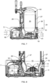
- Fig. 1 shows a vertical cross-section along the axis S1 (as shown in Fig. 2 ) of a beverage dispensing system with a cooling arrangement 1 according to an embodiment of the present disclosure.
- the beverage dispensing system is configured for dispensing a beverage from a beverage container 15 arranged therein.
- the beverage may be include but not limited to beer, a carbonated malt-based beverage, non-alcoholic beer, or cider.
- the beverage container 15 may be a lightweight, collapsible and disposable beverage container (keg).
- the collapsible beverage container 15 can be made of thin and flexible plastic material or may even be in the form of a plastic bag.
- the tap handle allows the operator to control the tapping valve and thereby the beverage dispensing operation.
- the tap handle is a part of a beverage font mounted in a bar, such as shown in e.g. Fig. 1 , or when using a smaller beverage dispensing system, the tap handle may be mounted on a housing 2 of the beverage dispensing system, and typically in front of the beverage container 15, as shown in e.g. Fig. 11 , so that the tap handle may be easily used by the operator to dispense the beverage.
- the beverage thus is dispensed from the beverage container 15 through a beverage dispensing line 29 connected on one end to a beverage outlet 17 of the beverage container 15 and arranged at least partially within the housing 2 and optionally also in drawn through beverage font assembly, when the beverage container 15 is received in the housing 2, as shown in more detail in Figs. 7 and 8 .
- the beverage dispensing system comprises a housing 2 with a bottom 3, a top 4, and a continuous side wall 5 together defining an enclosure for receiving at least a portion of a beverage container 15.
- the side wall 5 comprises an inner side 51 towards the enclosure and an outer side 52 towards a space outside the housing 2.
- At least one inlet aperture 62 is arranged in the side wall 5 for allowing airflow from a space outside the housing 2 into the enclosure (illustrated by the arrows on the left); while a further at least one outlet aperture 61 is also arranged in the side wall 5 downstream from the inlet aperture 62 for allowing airflow from the enclosure to a space outside the housing 2 (illustrated by the arrows on the right).
- An air channel 7 is arranged in the housing 2 to extend at least between the inlet aperture 62 and the outlet aperture 61 (better shown in the horizontal cross-sections of Fig. 2 and 3 ).
- the air channel 7 extends along the inner side 51 of the side wall 5.
- the system further comprises heat exchange means 8 arranged in the housing 2 for receiving heat from the beverage container 15 when the beverage container 15 is received housing 2 as part of a cooling arrangement 1.
- a condenser 11 is arranged in the air channel 7 and in thermal connection with the heat exchange means 8, so that the condenser 11 can emit heat received from the beverage container 15 to the air channel 7.
- the heat exchange means 8 may be a heat sink wall 9 arranged in thermal connection with the beverage container 15 when the beverage container 15 is received in the housing 2, as shown in Fig. 2 , and better illustrated in Fig. 4 and 9 .
- An evaporator 10 may also be arranged in thermal connection with the heat sink wall 9.
- the cooling device 1 can further comprise, as part of the cooling arrangement 1, a compressor 12 which can provide a fix or adjustable pressure.
- the evaporator 10, the compressor 12, and the condenser 11 is interconnected through a cooling duct 13 for circulating a cooling substance; the duct further comprising an expansion valve 14 being arranged in the duct between the condenser 11 and the evaporator 10 to provide a vapor-compression cycle for cooling the beverage container 15.
- the cooling substance may be a refrigerant comprising at least one of hydrocarbon and hydrofluoroolefin, such as R-32, R-290, R-600a, R-454b, R-1234yf, R-514A, R-744 CO2,R-1234ze and R-1233zd, most preferably R-600a.
- a pressure source 43 can be further arranged in the housing 2 for providing an elevated pressure from a gas supply and for applying this pressure on the beverage container 15 to dispense a beverage.
- the pressure source 43 is in fluid communication with an inner space of the housing 2 for pressurizing and applying a force onto the beverage container 15, collapsing the beverage container 15 and forcing the beverage through the beverage dispensing line 29 and out through the tapping head.
- Fig. 2 shows a schematic horizontal cross-section along the axis S2 of the beverage dispensing system in accordance with an embodiment of the present disclosure.
- Fig. 2 shows a schematic horizontal cross-section along the axis S2 of the beverage dispensing system in accordance with an embodiment of the present disclosure.
- the housing 2 may comprise a first housing portion 21 for receiving the beverage container 15; and a second housing portion 22 arranged laterally to the first housing portion 21 and connected to the first housing portion 21 through the side wall 5.
- the outlet apertures 61 are arranged in the side wall 5 of the first housing portion 21; and the inlet apertures 62 are arranged in the side wall 5 of the second housing portion 22, thereby allowing a channeled airflow between an outer side 52 of the first housing portion 21 and an outer side 52 of the second housing portion 22 through the air channel 7.
- both the heat exchange means 8 and the condenser 11 is arranged in the first housing portion 21; while the compressor 12 is arranged in the second housing portion 22.
- At least one ventilator 19 is arranged in the air channel 7 for providing forced air flow in the air channel 7 at a fixed or adjustable speed.
- at least two ventilators 19 are arranged in the air channel 7, along opposite sides of the housing 2, the at least two ventilators 19 being arranged in parallel to provide a unilateral air flow, wherein air flows through all the ventilators 19 from the inlet aperture 62 to the outlet aperture 61.
- the first housing portion 21 may be larger than the second housing portion 22, and the condenser 11 may be arranged in the first housing portion 21 so that it can provide a larger surface.
- the condenser 11 may be arranged at a side of the first housing portion 21 facing away from the second housing portion 22.
- the second housing portion 22 is larger than the first housing portion 21, and the condenser 11 is arranged in the second housing portion 22, at a side of the second housing portion 22 facing away from the first housing portion 21.
- Fig. 3 shows a detailed horizontal cross-section along the axis S2 of a beverage dispensing system with a cooling arrangement in accordance with an embodiment of the present disclosure.
- the housing 2 is defined horizontally by a rounded hourglass shape, the side wall 5 comprising four curved segments 31 (explained in more detail at Fig. 6 ), the four curved segments 31 comprising two concave curved segments 34 and two convex curved segments 35 arranged intermittently.
- the condenser 11 and the compressor 12 in these embodiments are arranged at respective concave curved segments 34.
- Fig. 4 shows an isometric view of a beverage dispensing system cut at a horizontal plane in accordance with an embodiment of the present disclosure.
- at least one partition wall 20 may further be arranged in the air channel 7 on an outflow side of the at least one ventilator 19.
- Each partition wall 20 can be arranged to fill the cross-section of the air channel 7, comprising a hole for restricting and channeling air flow from the respective ventilator 19 through the partition wall 20.
- At least one partition wall 20 may further comprise flow directing means 23 for directing air flow from the partition wall 20 within the air channel 7, the flow directing means 23 being arranged on an opposite side of the at least one partition wall 20 to the ventilator 19.
- the flow directing means 23 may be in the form of a tapered spout of an adjustable or fixed direction, with a fixed or adjustable diameter.
- the cooling arrangement 1 may further comprise an additional heat sink layer 27, made from a material of high thermal conductivity such as aluminium, for providing additional cooling when the beverage container 15 is received in the receptacle 24.
- the heat sink layer 27 may be arranged in a base portion 25 or a lid portion 26 of the housing 2, depending on location of the connection between the base 25 and the lid 26, i.e. which portion has larger surface area.
- the side wall 5 may comprise an inlet segment 38 comprising a set of inlet apertures including the inlet aperture 62; and an outlet segment 36 comprising a set of outlet apertures including the outlet aperture 61.
- the embodiment illustrated in Fig. 6B is not according to the invention and is present for illustration purposes only.
- At least one continuous segment 37 uninterrupted by apertures is also arranged between the inlet segment 38 and the outlet segment 36.
- the side wall is apertured all along.
- the condenser 11 can be arranged in the air channel 7 in front of the outlet segment 36 for enabling efficient heat emission through the side wall 5.
- the condenser 11 is arranged in parallel to the outlet segment 36, with a clearance arranged between the condenser 11 and the outlet segment 36.
- the side wall 5 comprises at least one curved segment 31.
- at least one of the inlet apertures 62 or the outlet apertures 61 is arranged in such a curved segment 31; and at least a portion of the condenser 11 is arranged in the air channel 7 along a curved segment 31, the condenser 11 comprising curved ducts 32 corresponding to the shape a respective curved segment 31.
- the curved segments 31 are shaped as a half cylinder.
- the side wall 5 comprises at least two curved segments 31 arranged at opposite sides of the housing 2, wherein the inlet aperture 62 and the outlet aperture 61 are arranged in different ones of the at least two curved segments 31; and wherein a compressor 12 is arranged in the housing 2 at a curved segment 31 opposite to the condenser 11.
- the condenser 11 may be arranged along at least a portion of the curved segment 31. In other possible embodiments the condenser 11 is arranged along the entirety of the curved segment 31, or the condenser 11 may even be extending over the curved segment 31 on at least on one end, as shown in Fig. 6A .
- the housing 2 has a cylindrical shape.
- the cylindrical shape may be defined by an oval, circular, or even elliptical cross section.
- the side wall 5 only comprises curved segments 31.
- the side wall 5 does not comprise any curved segments.
- Figs. 6B and 12B are not according to the invention and are present for illustration purposes only.
- the side wall 5 only comprises two curved segments 31, the two curved segments 31 being connected by straight segments 33, providing a straight slot shape for the housing 2.
- the housing 2 may comprise a receptacle 24 for receiving the beverage container 15, the receptacle 24 comprising a base portion 25 and an at least partially removable lid portion 26.
- the receptacle 24 can define a sealable pressure chamber 44 when the lid portion 26 is attached to the base portion 25, and pressurized fluid from the pressure source 43 can be applied to the pressure chamber 44 for pressurizing the beverage container 15 to dispense a beverage.
- the beverage container 15 may comprise a closure 16 with a beverage outlet 17.
- the housing 2 comprises a cavity 18 designed to accommodate the closure 16 and at least a portion of the beverage container 15 when the beverage container 15 is received in the housing 2.
- the cavity 18 is delimited at least partially by the heat sink wall 9 with evaporator 10 lines arranged in a spiral to at least partially surround the heat sink wall 9 for cooling the beverage container 15.
- the heat exchange means 8 comprising the evaporator 10 arranged in thermal connection with the heat sink wall 9 may be arranged in the base portion 25, and at least a portion of the additional heat sink layer 27 as described before can be arranged in the lid portion 26.
- the housing 2 may further comprise a thermal bridge 28 of any known and suitable means, arranged between the base portion 25 and the lid portion 26, providing a thermally conductive connection between the additional heat sink layer 27 and any of the heat exchange means 8.
- the beverage dispensing line 29 connected on one end to a beverage outlet 17, and the cooling arrangement 1 comprises a compressor 12 that can emit heat.
- a heat insulation layer 30 may be arranged between at least a portion of the beverage dispensing line 29 and the compressor 12.
- At least one portion of the beverage dispensing line 29 may be disposed in thermal connection with the heat sink layer 27, when the beverage container 15 is received in the housing 2, for providing additional cooling for the beverage flowing in the beverage dispensing line 29.
- This can be achieved by for example arranging the portion of the beverage dispensing line 29 to run close to the beverage container 15 and using a metal-based thermal bridge between the heat sink layer 27 and the portion of the beverage dispensing line 29.
- Fig. 9 shows a partial isometric cross-section along the axis S1 of a beverage dispensing system with a cooling arrangement 1 in accordance with an embodiment of the disclosure.
- a heat insulation layer 30 is arranged between a portion of the beverage dispensing line 29 and the compressor 12.
- the figure also illustrates the inlet segment 38 comprising a set of horizontal inlet apertures 62; and an outlet segment 36 comprising a set of horizontal outlet apertures 61.
- the condenser 11 as shown in the right side of the figure is arranged in the air channel 7 along a curved back side of the housing, the condenser 11 comprising curved ducts 32 corresponding to the shape a respective curved segment 31.
- the air channel 7 extends between the compressor 12 and the inlet segment 38.
- Fig. 10 shows a partial isometric side view of a beverage dispensing system in accordance with an embodiment of the disclosure, wherein the housing and some further parts are removed for better visibility of parts of the cooling arrangement 1.
- a partition wall 20 is shown arranged in the air channel 7 on an outflow side of a ventilator 19.
- the partition wall 20 is be arranged to fill the cross-section of the air channel 7, comprising a hole for restricting and channeling air flow from the ventilator 19 through the partition wall 20.
- Fig. 10 furthers shows a practical arrangement of the cooling duct connecting the compressor 12 with the evaporator 10 (now shown).
- the figure also shows the arrangement of the base portion 25 and the removable lid portion 26 defining a sealable pressure chamber 44 as the lid portion 26 is attached to the base portion 25.
- the condenser 11 comprises curved ducts 32 corresponding to the shape a respective curved segment 31 of the side wall 5 (not shown).
- Fig. 11 show a schematic vertical cross-section of a beverage dispensing system in accordance with further possible embodiments of the present disclosure, wherein the tapping head is directly mounted on a body 5 of the beverage dispensing system.
- the beverage container 15 may comprise a beverage filled bag 40 inside an outer shell 41, wherein pressurized fluid from the pressure source 43 can be applied to a space 42 between the outer shell 41 and the bag 40 for pressurizing the beverage container 15 to dispense a beverage.
- this alternative embodiment comprises corresponding structures and features that are the same or similar to corresponding structures and features previously described and are shown herein denoted by the same reference numeral as previously used for simplicity, such as an evaporator 10, a condenser 11, and a compressor 12.
- the housing 2 comprises evaporator 10 lines arranged in a spiral to surround the lower portion of the beverage container 15, which is arranged with a beverage outlet 17 connected to a beverage dispensing line 29 that leads to a tapping head.
- the housing 2 may comprise a receptacle 24 for receiving the beverage container 15, the receptacle 24 comprising a base portion 25 and an at least partially removable lid portion 26.
- At least one inlet aperture 62 is arranged in the side wall 5 of the housing 2 for allowing airflow from a space outside the housing 2 into the enclosure (illustrated by the arrows on the left); while a further at least one outlet aperture 61 is also arranged in the side wall 5 downstream from the inlet aperture 62 for allowing airflow from the enclosure to a space outside the housing 2 (illustrated by the arrows on the right).
- An air channel 7 is arranged in the housing 2 of all embodiments to extend at least between the inlet aperture 62 and the outlet aperture 61.
- the air channel 7 in all cases extends along an inner side of the side wall 5.
- the side wall 5 may comprise an inlet segment 38 comprising a set of inlet apertures 62; and an outlet segment 36 comprising a set of outlet apertures 61.
- at least one continuous segment 37 uninterrupted by apertures is also arranged between the inlet segment 38 and the outlet segment 36, however it is also possible that the side wall is apertured all along.
- the condenser 11 as shown can be arranged in the air channel 7 in front of the outlet segment 36 for enabling efficient heat emission through the side wall 5.
- the condenser 11 is arranged in parallel to the outlet segment 36, in a curved shape, with a clearance arranged between the condenser 11 and the outlet segment 36.
- Figs. 12A and 12B show schematic horizontal cross-sections of beverage dispensing systems, corresponding to the embodiment of Fig. 11 using a double-layered beverage container 15.
- the embodiment illustrated in Fig. 12B is not according to the invention and is present for illustration purposes only.
- the housing 2 has a substantially cylindrical shape.
- the cylindrical shape may be defined by an oval, circular, or even elliptical cross section.
- the side wall 5 only comprises curved segments 31.
- the side wall 5 does not comprise any curved segments.
- the beverage dispensing system may further comprise a first electric power unit including a mains supply and a second power unit including a battery supply, and, optionally, a third power supply including a solar power supply.
- a mains power supply e.g. 115V or 230V AC household supply
- Batteries may advantageously be used in mobile appliances.
- the batteries may e.g. be rechargeable by the use of a mains supply and a power converter.
- Solar power may be used for directly powering the beverage dispensing system, however, due to the limited output of solar cells when no direct sunlight is available it is mostly considered an auxiliary power unit to be used in conjunction with rechargeable batteries.
- a computer program may be stored/distributed on a suitable medium, such as an optical storage medium or a solid-state medium supplied together with or as part of other hardware, but may also be distributed in other forms, such as via the Internet or other wired or wireless telecommunication systems.
- a suitable medium such as an optical storage medium or a solid-state medium supplied together with or as part of other hardware, but may also be distributed in other forms, such as via the Internet or other wired or wireless telecommunication systems.
Landscapes
- Engineering & Computer Science (AREA)
- Physics & Mathematics (AREA)
- Thermal Sciences (AREA)
- Mechanical Engineering (AREA)
- General Engineering & Computer Science (AREA)
- Chemical & Material Sciences (AREA)
- Combustion & Propulsion (AREA)
- Devices For Dispensing Beverages (AREA)
- Devices That Are Associated With Refrigeration Equipment (AREA)
Claims (15)
- Getränkeausgabesystem, umfassendein Gehäuse (2), umfassend einen Boden (3), eine Oberseite (4) und eine durchgehende Seitenwand (5), die zusammen ein Gehäuse zum Aufnehmen mindestens eines Abschnitts eines Getränkebehälters (15) definieren, die Seitenwand (5) umfassend mindestens ein gekrümmtes Segment (31);eine Druckquelle (43) zum Anwenden von Druck auf den Getränkebehälter (15), um ein Getränk auszugeben;eine Einlassöffnung (62), die in der Seitenwand (5) angeordnet ist, um einen Luftstrom von einem Raum außerhalb des Gehäuses (2) in das Gehäuse zu ermöglichen;eine Auslassöffnung (61), die in der Seitenwand (5) stromabwärts von der Einlassöffnung (62) angeordnet ist, um einen Luftstrom von dem Gehäuse zu einem Raum außerhalb des Gehäuses (2) zu ermöglichen;einen Luftkanal (7), der sich zumindest zwischen der Einlassöffnung (62) und der Auslassöffnung (61) erstreckt; undeine Kühlvorrichtung (1), umfassend:Wärmetauscheinrichtungen (8), die in dem Gehäuse (2) angeordnet sind, um Wärme von dem Getränkebehälter (15) aufzunehmen, wenn der Getränkebehälter (15) in dem Gehäuse (2) aufgenommen ist; undeinen Kondensator (11), der in dem Luftkanal (7) angeordnet ist und in thermischer Verbindung mit den Wärmetauscheinrichtungen (8) ist, zum Abgeben von Wärme, die von dem Getränkebehälter (15) empfangen wird, an den Luftkanal (7), dadurch gekennzeichnet, dass:mindestens eine von der Einlassöffnung (62) oder der Auslassöffnung (61) in dem mindestens einen gekrümmten Segment (31) angeordnet ist; undwobei mindestens ein Abschnitt des Kondensators (11) in dem Luftkanal (7) entlang des mindestens einen gekrümmten Segments (31) angeordnet ist, wobei der Kondensator (11) gekrümmte Kanäle (32) umfasst, die der Form eines jeweiligen gekrümmten Segments (31) entsprechen.
- Getränkeausgabesystem nach Anspruch 1, wobei die Wärmetauscheinrichtungen (8) eine Kühlkörperwand (9), die in thermischer Verbindung mit dem Getränkebehälter (15) angeordnet ist, wenn der Getränkebehälter (15) in dem Gehäuse (2) aufgenommen ist, und einen Verdampfer (10), der in thermischer Verbindung mit der Kühlkörperwand (9) angeordnet ist, umfassen;wobei die Kühlvorrichtung (1) ferner einen Verdichter (12) umfasst;wobei der Verdampfer (10), der Verdichter (12) und der Kondensator (11) durch einen Kühlkanal (13) miteinander verbunden sind, um eine Kühlsubstanz umzuwälzen; undder Kanal ferner umfassend ein Expansionsventil (14), das in der Leitung zwischen dem Kondensator (11) und dem Verdampfer (10) angeordnet ist, um einen Dampfverdichtungszyklus zum Kühlen des Getränkebehälters (15) bereitzustellen.
- Getränkeausgabesystem nach Anspruch 2, wobei der Getränkebehälter (15) einen Verschluss (16) mit einem Getränkeauslass (17) umfasst,
wobei das Gehäuse (2) einen Hohlraum (18) umfasst, der konstruiert ist, um den Verschluss (16) und zumindest einen Teil des Getränkebehälters (15) aufzunehmen, wenn der Getränkebehälter (15) in dem Gehäuse (2) aufgenommen ist, und wobei der Hohlraum (18) zumindest teilweise durch die Kühlkörperwand (9) begrenzt ist, wobei der Verdampfer (10) zumindest teilweise die Kühlkörperwand (9) umgebend angeordnet ist, um den Getränkebehälter (15) zu kühlen. - Getränkeausgabesystem nach einem der Ansprüche 1 bis 3, wobei das Gehäuse (2) Folgendes umfasst:einen ersten Gehäuseabschnitt (21) zum Aufnehmen des Getränkebehälters (15);einen zweiten Gehäuseabschnitt (22), der seitlich zu dem ersten Gehäuseabschnitt (21) angeordnet und durch die Seitenwand (5) mit dem ersten Gehäuseabschnitt (21) verbunden ist; und wobei die Auslassöffnung (61) in der Seitenwand (5) des ersten Gehäuseabschnitts (21) angeordnet ist; unddie Einlassöffnung (62) in der Seitenwand (5) des zweiten Gehäuseabschnitts (22) angeordnet ist, wodurch ein kanalisierter Luftstrom zwischen einer Außenseite (52) des ersten Gehäuseabschnitts (21) und einer Außenseite (52) des zweiten Gehäuseabschnitts (22) durch den Luftkanal (7) ermöglicht wird, wobei sowohl die Wärmetauscheinrichtungen (8) als auch der Kondensator (11) in dem ersten Gehäuseabschnitt (21) angeordnet sind; undwobei ein Verdichter (12) in dem zweiten Gehäuseabschnitt (22) angeordnet ist.
- Getränkeausgabesystem nach einem der Ansprüche 1 bis 4, wobei mindestens ein Lüfter (19) in dem Luftkanal (7) angeordnet ist, um einen erzwungenen Luftstrom in dem Luftkanal (7) bereitzustellen.
- Getränkeausgabesystem nach Anspruch 5, wobei in dem Luftkanal (7) mindestens eine Trennwand (20) auf einer Ausströmseite des mindestens einen Lüfters (19) angeordnet ist, wobei jede Trennwand (20) angeordnet ist, um den Querschnitt des Luftkanals (7) auszufüllen, und jede Trennwand (20) ein Loch zum Beschränken und Leiten des Luftstroms von dem jeweiligen Lüfter (19) durch die Trennwand (20) umfasst.
- Getränkeausgabesystem nach Anspruch 6, wobei mindestens eine Trennwand (20) ferner Strömungsleiteinrichtungen (23) zum Leiten eines Luftstroms von der Trennwand (20) innerhalb des Luftkanals (7) umfasst, wobei die Strömungsleiteinrichtungen (23) auf einer gegenüberliegenden Seite der mindestens einen Trennwand (20) zu dem Lüfter (19) angeordnet sind.
- Getränkeausgabesystem nach einem der Ansprüche 1 bis 7, wobei das Gehäuse (2) eine Aufnahme (24) zum Aufnehmen des Getränkebehälters (15) umfasst, die Aufnahme (24) umfassend einen Basisabschnitt (25) und einen zumindest teilweise entfernbaren Deckelabschnitt (26); und
wobei das Behältnis (24) ferner eine zusätzliche Kühlkörperwand (27) umfasst, die in mindestens einem von dem Basisabschnitt (25) oder dem Deckelabschnitt (26) angeordnet ist, um zusätzliche Kühlung bereitzustellen, wenn der Getränkebehälter (15) in der Aufnahme (24) aufgenommen ist. - Getränkeausgabesystem nach Anspruch 8, wobei mindestens ein Abschnitt der zusätzlichen Kühlkörperwand (27) in dem Deckelabschnitt (26) angeordnet ist,wobei die Wärmetauscheinrichtungen (8) in dem Basisabschnitt (25) angeordnet sind; undwobei das Gehäuse (2) ferner eine Wärmebrücke (28) umfasst, die zwischen dem Basisabschnitt (25) und dem Deckelabschnitt (26) angeordnet ist und eine wärmeleitende Verbindung zwischen der zusätzlichen Kühlkörperschicht (27) und den Wärmetauscheinrichtungen (8) bereitstellt.
- Getränkeausgabesystem nach einem der Ansprüche 8 oder 9, wobei die Aufnahme (24) eine verschließbare Druckkammer (44) definiert, wenn der Deckelabschnitt (26) an dem Basisabschnitt (25) angebracht ist, und wobei unter Druck stehendes Fluid von der Druckquelle (43) an die Druckkammer (44) angelegt werden kann, um den Getränkebehälter (15) unter Druck zu setzen, um ein Getränk auszugeben.
- Getränkeausgabesystem nach einem der Ansprüche 1 bis 9, wobei der Getränkebehälter (15) einen mit Getränk gefüllten Beutel (40) innerhalb einer äußeren Hülle (41) umfasst, wobei unter Druck stehendes Fluid von der Druckquelle (43) auf einen Raum (42) zwischen der äußeren Hülle (41) und dem Beutel (40) angewendet werden kann, um den Getränkebehälter (15) unter Druck zu setzen, um ein Getränk auszugeben.
- Getränkeausgabesystem nach einem der Ansprüche 1 bis 11, wobei das Getränkeausgabesystem eine Getränkeausgabeleitung (29) umfasst, die an einem Ende mit einem Getränkeauslass (17) des Getränkebehälters (15) verbunden ist und zumindest teilweise innerhalb des Gehäuses (2) angeordnet ist, wenn der Getränkebehälter (15) in dem Gehäuse (2) aufgenommen ist; wobei die Kühlvorrichtung (1) einen Verdichter (12) umfasst; und
wobei die Kühlvorrichtung (1) ferner eine Wärmeisolierungsschicht (30) umfasst, die zwischen mindestens einem Abschnitt der Getränkeausgabeleitung (29) und dem Verdichter (12) angeordnet ist. - Getränkeausgabesystem nach Anspruch 12, wobei eine Kühlkörperschicht (27) in dem Gehäuse (2) angeordnet ist, um eine zusätzliche Kühlung für den Getränkebehälter (15) bereitzustellen; und wobei mindestens ein Abschnitt der Getränkeausgabeleitung (29) in thermischer Verbindung mit der Kühlkörperschicht (27) angeordnet ist, wenn der Getränkebehälter (15) in dem Gehäuse (2) aufgenommen ist, um eine zusätzliche Kühlung für ein Getränk bereitzustellen, das in der Getränkeausgabeleitung (29) fließt.
- Getränkeausgabesystem nach einem der Ansprüche 1 bis 13, wobei die Seitenwand (5) mindestens zwei gekrümmte Segmente (31) umfasst, die auf gegenüberliegenden Seiten des Gehäuses (2) angeordnet sind, wobei die Einlassöffnung (62) und die Auslassöffnung (61) in unterschiedlichen der mindestens zwei gekrümmten Segmente (31) angeordnet sind; und wobei ein Verdichter (12) in dem Gehäuse (2) an einem gekrümmten Segment (31) gegenüber dem Kondensator (11) angeordnet ist.
- Getränkeausgabesystem nach Anspruch 14, wobei das Gehäuse (2) horizontal durch eine abgerundete Sanduhrform definiert ist, wobei die Seitenwand (5) vier gekrümmte Segmente (31) umfasst, die vier gekrümmten Segmente (31) umfassend zwei konkave gekrümmte Segmente (34) und zwei konvexe gekrümmte Segmente (35), die intermittierend angeordnet sind; und wobei der Kondensator (11) und der Verdichter (12) an jeweiligen konkaven gekrümmten Segmenten (34) angeordnet sind.
Priority Applications (17)
| Application Number | Priority Date | Filing Date | Title |
|---|---|---|---|
| HUE22158861A HUE070673T2 (hu) | 2022-02-25 | 2022-02-25 | Italadagoló rendszer hûtõberendezése |
| PT221588619T PT4234478T (pt) | 2022-02-25 | 2022-02-25 | Dispositivo de refrigeração para um sistema de distribuição de bebidas |
| EP22158861.9A EP4234478B1 (de) | 2022-02-25 | 2022-02-25 | Kühlanordnung für ein getränkeabgabesystem |
| FIEP22158861.9T FI4234478T3 (fi) | 2022-02-25 | 2022-02-25 | Jäähdytysjärjestely juoma-annostelujärjestelmää varten |
| PL22158861.9T PL4234478T3 (pl) | 2022-02-25 | 2022-02-25 | Układ chłodzenia układu dozowania napojów |
| ES22158861T ES3009504T3 (en) | 2022-02-25 | 2022-02-25 | Cooling arrangement for a beverage dispensing system |
| DK22158861.9T DK4234478T3 (da) | 2022-02-25 | 2022-02-25 | Køleanordning til drikkevaredispenseringssystem |
| IL315054A IL315054A (en) | 2022-02-25 | 2023-02-24 | Cooling arrangement for a beverage dispensing system |
| PCT/EP2023/054642 WO2023161396A1 (en) | 2022-02-25 | 2023-02-24 | Cooling arrangement for a beverage dispensing system |
| AU2023223577A AU2023223577A1 (en) | 2022-02-25 | 2023-02-24 | Cooling arrangement for a beverage dispensing system |
| CA3252844A CA3252844A1 (en) | 2022-02-25 | 2023-02-24 | COOLING ARRANGEMENT FOR A BEVERAGE DISPENSING SYSTEM |
| JP2024548688A JP2025506715A (ja) | 2022-02-25 | 2023-02-24 | 飲料ディスペンスシステム用冷却装置 |
| KR1020247031880A KR20240158269A (ko) | 2022-02-25 | 2023-02-24 | 음료 분배 시스템을 위한 냉각 장치 |
| US18/839,512 US20250162853A1 (en) | 2022-02-25 | 2023-02-24 | Cooling arrangement for a beverage dispensing system |
| CN202380023558.9A CN119013221B (zh) | 2022-02-25 | 2023-02-24 | 用于饮料分配系统的冷却设备 |
| MX2024010183A MX2024010183A (es) | 2022-02-25 | 2024-08-19 | Dispositivo de enfriamiento para un sistema dispensador de bebidas |
| ZA2024/07131A ZA202407131B (en) | 2022-02-25 | 2024-09-17 | Cooling arrangement for a beverage dispensing system |
Applications Claiming Priority (1)
| Application Number | Priority Date | Filing Date | Title |
|---|---|---|---|
| EP22158861.9A EP4234478B1 (de) | 2022-02-25 | 2022-02-25 | Kühlanordnung für ein getränkeabgabesystem |
Publications (2)
| Publication Number | Publication Date |
|---|---|
| EP4234478A1 EP4234478A1 (de) | 2023-08-30 |
| EP4234478B1 true EP4234478B1 (de) | 2024-12-18 |
Family
ID=80461223
Family Applications (1)
| Application Number | Title | Priority Date | Filing Date |
|---|---|---|---|
| EP22158861.9A Active EP4234478B1 (de) | 2022-02-25 | 2022-02-25 | Kühlanordnung für ein getränkeabgabesystem |
Country Status (17)
| Country | Link |
|---|---|
| US (1) | US20250162853A1 (de) |
| EP (1) | EP4234478B1 (de) |
| JP (1) | JP2025506715A (de) |
| KR (1) | KR20240158269A (de) |
| CN (1) | CN119013221B (de) |
| AU (1) | AU2023223577A1 (de) |
| CA (1) | CA3252844A1 (de) |
| DK (1) | DK4234478T3 (de) |
| ES (1) | ES3009504T3 (de) |
| FI (1) | FI4234478T3 (de) |
| HU (1) | HUE070673T2 (de) |
| IL (1) | IL315054A (de) |
| MX (1) | MX2024010183A (de) |
| PL (1) | PL4234478T3 (de) |
| PT (1) | PT4234478T (de) |
| WO (1) | WO2023161396A1 (de) |
| ZA (1) | ZA202407131B (de) |
Family Cites Families (27)
| Publication number | Priority date | Publication date | Assignee | Title |
|---|---|---|---|---|
| US1942741A (en) * | 1931-01-02 | 1934-01-09 | Louis L Austin | Water cooler |
| US3712514A (en) * | 1971-03-29 | 1973-01-23 | R Leblanc | Portable beer dispenser |
| US3889487A (en) | 1972-05-18 | 1975-06-17 | Sandor Frankfurt | Cooling system for beverage coolers |
| DE19720553C2 (de) * | 1997-05-16 | 1999-07-15 | Kall Schanktechnik Gmbh | Getränkekühl- und -zapfgerät |
| EP1003686B1 (de) * | 1997-09-04 | 2002-06-26 | Heineken Technical Services B.V. | Vorrichtung zum lagern und abgeben von bier und anderen co2 enthaltenden getränken |
| US6178753B1 (en) | 1999-04-19 | 2001-01-30 | Ontro, Inc. | Container with self-heating module having liquid reactant and breakable reactant barrier at distal end of module |
| DE60009508D1 (de) | 1999-08-04 | 2004-05-06 | Crown Cork & Seal Tech Corp | Selbstkühlende dose |
| US6266879B1 (en) | 1999-08-26 | 2001-07-31 | Ontro, Inc. | Container with integral module for heating or cooling the contents and method for its manufacture |
| NL1015359C2 (nl) | 2000-05-31 | 2001-12-03 | Heineken Tech Services | Tapinrichting en houder daarvoor, alsmede werkwijze voor vervaardiging daarvan. |
| US20060175355A1 (en) * | 2005-02-09 | 2006-08-10 | Glucksman Dov Z | Beverage dispenser |
| CN101282902A (zh) * | 2005-08-12 | 2008-10-08 | 嘉士伯酿酒有限公司 | 一种用来从可变形的罐中分配饮料的装置 |
| MY163766A (en) | 2005-08-12 | 2017-10-31 | Carlsberg Breweries As | An assembly for dispensing beverage |
| WO2007019851A1 (en) | 2005-08-12 | 2007-02-22 | Carlsberg Breweries A/S | Method and assembly for guiding a dispensing line through a beverage dispenser |
| US8360277B2 (en) | 2005-08-12 | 2013-01-29 | Carlsberg Breweries A/S | Assembly for dispensing beverage |
| EP1937585A2 (de) | 2005-08-12 | 2008-07-02 | Carlsberg Breweries A/S | Anordnung zur ausgabe eines getränks |
| EA012237B1 (ru) * | 2005-08-12 | 2009-08-28 | Карлсберг Брюириз А/С | Охлаждение выдачной линии |
| NL2000339C2 (nl) * | 2006-11-28 | 2009-02-18 | Konink Grolsch N V | Inrichting voor het koelen en in gekoelde toestand houden van een met drank gevulde houder. |
| US7849919B2 (en) | 2007-06-22 | 2010-12-14 | Lockheed Martin Corporation | Methods and systems for generating and using plasma conduits |
| EP2504272B1 (de) * | 2009-11-23 | 2013-11-13 | Carlsberg Breweries A/S | Verfahren zum installieren eines zusammenklappbaren getränkebehälters in einem getränkeautomaten |
| US9845988B2 (en) * | 2014-02-18 | 2017-12-19 | Supercooler Technologies, Inc. | Rapid spinning liquid immersion beverage supercooler |
| US10065848B2 (en) * | 2015-10-08 | 2018-09-04 | Dee Volin | Unique self-pressurizing, self-cooling beverage system, having impact-and-vibration-absorbing systems, anti-shaking anti-rolling clamping system, root-beer-float system, beverage-dispensing system, and multi-height spigot system |
| EP3246389B1 (de) | 2016-05-18 | 2024-07-03 | LG Electronics Inc. | Bierzubereiter |
| NL2018955B1 (en) | 2017-05-19 | 2018-11-28 | Heineken Supply Chain Bv | Beverage dispensing assembly and beverage container |
| NL2018956B1 (en) * | 2017-05-19 | 2018-11-28 | Heineken Supply Chain Bv | Beverage dispensing assembly and beverage container |
| KR102183690B1 (ko) * | 2017-05-22 | 2020-11-27 | 엘지전자 주식회사 | 음료 제조팩 및 이를 포함하는 음료 제조기 |
| WO2020140135A1 (en) * | 2018-12-31 | 2020-07-09 | Zanette & Sons Pty Ltd | Method and apparatus for dispensing a beverage in chilled condition |
| NL2024209B1 (en) * | 2019-11-11 | 2021-07-28 | Heineken Supply Chain Bv | Cooling system for a liquid dispensing assembly |
-
2022
- 2022-02-25 EP EP22158861.9A patent/EP4234478B1/de active Active
- 2022-02-25 HU HUE22158861A patent/HUE070673T2/hu unknown
- 2022-02-25 PT PT221588619T patent/PT4234478T/pt unknown
- 2022-02-25 PL PL22158861.9T patent/PL4234478T3/pl unknown
- 2022-02-25 FI FIEP22158861.9T patent/FI4234478T3/fi active
- 2022-02-25 DK DK22158861.9T patent/DK4234478T3/da active
- 2022-02-25 ES ES22158861T patent/ES3009504T3/es active Active
-
2023
- 2023-02-24 JP JP2024548688A patent/JP2025506715A/ja active Pending
- 2023-02-24 AU AU2023223577A patent/AU2023223577A1/en active Pending
- 2023-02-24 US US18/839,512 patent/US20250162853A1/en active Pending
- 2023-02-24 CN CN202380023558.9A patent/CN119013221B/zh active Active
- 2023-02-24 CA CA3252844A patent/CA3252844A1/en active Pending
- 2023-02-24 IL IL315054A patent/IL315054A/en unknown
- 2023-02-24 WO PCT/EP2023/054642 patent/WO2023161396A1/en not_active Ceased
- 2023-02-24 KR KR1020247031880A patent/KR20240158269A/ko active Pending
-
2024
- 2024-08-19 MX MX2024010183A patent/MX2024010183A/es unknown
- 2024-09-17 ZA ZA2024/07131A patent/ZA202407131B/en unknown
Also Published As
| Publication number | Publication date |
|---|---|
| CN119013221B (zh) | 2025-10-28 |
| FI4234478T3 (fi) | 2025-02-10 |
| MX2024010183A (es) | 2024-11-08 |
| US20250162853A1 (en) | 2025-05-22 |
| ZA202407131B (en) | 2025-06-25 |
| HUE070673T2 (hu) | 2025-07-28 |
| IL315054A (en) | 2024-10-01 |
| DK4234478T3 (da) | 2025-02-24 |
| KR20240158269A (ko) | 2024-11-04 |
| PL4234478T3 (pl) | 2025-03-31 |
| ES3009504T3 (en) | 2025-03-27 |
| PT4234478T (pt) | 2025-02-03 |
| CN119013221A (zh) | 2024-11-22 |
| EP4234478A1 (de) | 2023-08-30 |
| AU2023223577A1 (en) | 2024-10-03 |
| WO2023161396A1 (en) | 2023-08-31 |
| CA3252844A1 (en) | 2023-08-31 |
| JP2025506715A (ja) | 2025-03-13 |
Similar Documents
| Publication | Publication Date | Title |
|---|---|---|
| US4993229A (en) | Bottled water cooling unit | |
| US5209069A (en) | Compact thermoelectrically cooled beverage dispenser | |
| US5718124A (en) | Chilled service bowl | |
| US7703301B2 (en) | Rapid fluid cooling system and refrigeration device having same | |
| CA2943482C (en) | Beverage dispensing appliance comprising a cooling unit | |
| CA2141501C (en) | Beverage dispenser | |
| US20060150637A1 (en) | Alcohol beverage dispensing apparatus | |
| US4765152A (en) | Beverage dispenser with a partitionless refrigerating stand | |
| KR20170002747U (ko) | 일체형 생맥주 냉각장치 | |
| EP4234478A1 (de) | Kühlanordnung für ein getränkeabgabesystem | |
| CN115947291B (zh) | 一种扎啤机 | |
| HK40099870A (en) | Cooling arrangement for a beverage dispensing system | |
| HK40099870B (en) | Cooling arrangement for a beverage dispensing system | |
| US20110006078A1 (en) | Beverage device and tank thereof | |
| JP2012233651A (ja) | 冷却庫 | |
| EA050169B1 (ru) | Охлаждающее устройство для системы выдачи напитка | |
| US5974825A (en) | Beverage dispenser with enhanced cooling efficiency | |
| KR102003804B1 (ko) | 생맥주 냉각장치 | |
| KR20070093633A (ko) | 음료수용 냉장고 | |
| JP2018111512A (ja) | 飲料注出装置 | |
| KR200245484Y1 (ko) | 음료 용기 냉장용 테이블 | |
| KR20030005782A (ko) | 냉장기능을 갖는 테이블 | |
| CN1774606A (zh) | 含酒精的饮料分配设备 | |
| ZA200504596B (en) | Alcohol beverage dispensing apparatus |
Legal Events
| Date | Code | Title | Description |
|---|---|---|---|
| PUAI | Public reference made under article 153(3) epc to a published international application that has entered the european phase |
Free format text: ORIGINAL CODE: 0009012 |
|
| STAA | Information on the status of an ep patent application or granted ep patent |
Free format text: STATUS: THE APPLICATION HAS BEEN PUBLISHED |
|
| AK | Designated contracting states |
Kind code of ref document: A1 Designated state(s): AL AT BE BG CH CY CZ DE DK EE ES FI FR GB GR HR HU IE IS IT LI LT LU LV MC MK MT NL NO PL PT RO RS SE SI SK SM TR |
|
| STAA | Information on the status of an ep patent application or granted ep patent |
Free format text: STATUS: REQUEST FOR EXAMINATION WAS MADE |
|
| 17P | Request for examination filed |
Effective date: 20240229 |
|
| RBV | Designated contracting states (corrected) |
Designated state(s): AL AT BE BG CH CY CZ DE DK EE ES FI FR GB GR HR HU IE IS IT LI LT LU LV MC MK MT NL NO PL PT RO RS SE SI SK SM TR |
|
| REG | Reference to a national code |
Ref country code: HK Ref legal event code: DE Ref document number: 40099870 Country of ref document: HK |
|
| GRAP | Despatch of communication of intention to grant a patent |
Free format text: ORIGINAL CODE: EPIDOSNIGR1 |
|
| STAA | Information on the status of an ep patent application or granted ep patent |
Free format text: STATUS: GRANT OF PATENT IS INTENDED |
|
| INTG | Intention to grant announced |
Effective date: 20240724 |
|
| GRAS | Grant fee paid |
Free format text: ORIGINAL CODE: EPIDOSNIGR3 |
|
| GRAA | (expected) grant |
Free format text: ORIGINAL CODE: 0009210 |
|
| STAA | Information on the status of an ep patent application or granted ep patent |
Free format text: STATUS: THE PATENT HAS BEEN GRANTED |
|
| RAP3 | Party data changed (applicant data changed or rights of an application transferred) |
Owner name: CARLSBERG BREWERIES A/S |
|
| AK | Designated contracting states |
Kind code of ref document: B1 Designated state(s): AL AT BE BG CH CY CZ DE DK EE ES FI FR GB GR HR HU IE IS IT LI LT LU LV MC MK MT NL NO PL PT RO RS SE SI SK SM TR |
|
| REG | Reference to a national code |
Ref country code: CH Ref legal event code: EP |
|
| REG | Reference to a national code |
Ref country code: DE Ref legal event code: R096 Ref document number: 602022008710 Country of ref document: DE |
|
| REG | Reference to a national code |
Ref country code: IE Ref legal event code: FG4D |
|
| REG | Reference to a national code |
Ref country code: PT Ref legal event code: SC4A Ref document number: 4234478 Country of ref document: PT Date of ref document: 20250203 Kind code of ref document: T Free format text: AVAILABILITY OF NATIONAL TRANSLATION Effective date: 20250127 |
|
| REG | Reference to a national code |
Ref country code: FI Ref legal event code: FGE |
|
| REG | Reference to a national code |
Ref country code: DK Ref legal event code: T3 Effective date: 20250221 |
|
| REG | Reference to a national code |
Ref country code: NL Ref legal event code: FP |
|
| REG | Reference to a national code |
Ref country code: SE Ref legal event code: TRGR |
|
| REG | Reference to a national code |
Ref country code: GR Ref legal event code: EP Ref document number: 20250400275 Country of ref document: GR Effective date: 20250314 |
|
| REG | Reference to a national code |
Ref country code: SK Ref legal event code: T3 Ref document number: E 45853 Country of ref document: SK |
|
| REG | Reference to a national code |
Ref country code: ES Ref legal event code: FG2A Ref document number: 3009504 Country of ref document: ES Kind code of ref document: T3 Effective date: 20250327 |
|
| REG | Reference to a national code |
Ref country code: LT Ref legal event code: MG9D |
|
| PG25 | Lapsed in a contracting state [announced via postgrant information from national office to epo] |
Ref country code: HR Free format text: LAPSE BECAUSE OF FAILURE TO SUBMIT A TRANSLATION OF THE DESCRIPTION OR TO PAY THE FEE WITHIN THE PRESCRIBED TIME-LIMIT Effective date: 20241218 |
|
| PG25 | Lapsed in a contracting state [announced via postgrant information from national office to epo] |
Ref country code: BG Free format text: LAPSE BECAUSE OF FAILURE TO SUBMIT A TRANSLATION OF THE DESCRIPTION OR TO PAY THE FEE WITHIN THE PRESCRIBED TIME-LIMIT Effective date: 20241218 |
|
| PG25 | Lapsed in a contracting state [announced via postgrant information from national office to epo] |
Ref country code: LV Free format text: LAPSE BECAUSE OF FAILURE TO SUBMIT A TRANSLATION OF THE DESCRIPTION OR TO PAY THE FEE WITHIN THE PRESCRIBED TIME-LIMIT Effective date: 20241218 |
|
| PG25 | Lapsed in a contracting state [announced via postgrant information from national office to epo] |
Ref country code: RS Free format text: LAPSE BECAUSE OF FAILURE TO SUBMIT A TRANSLATION OF THE DESCRIPTION OR TO PAY THE FEE WITHIN THE PRESCRIBED TIME-LIMIT Effective date: 20250318 |
|
| PG25 | Lapsed in a contracting state [announced via postgrant information from national office to epo] |
Ref country code: SM Free format text: LAPSE BECAUSE OF FAILURE TO SUBMIT A TRANSLATION OF THE DESCRIPTION OR TO PAY THE FEE WITHIN THE PRESCRIBED TIME-LIMIT Effective date: 20241218 |
|
| PG25 | Lapsed in a contracting state [announced via postgrant information from national office to epo] |
Ref country code: IS Free format text: LAPSE BECAUSE OF FAILURE TO SUBMIT A TRANSLATION OF THE DESCRIPTION OR TO PAY THE FEE WITHIN THE PRESCRIBED TIME-LIMIT Effective date: 20250418 |
|
| PG25 | Lapsed in a contracting state [announced via postgrant information from national office to epo] |
Ref country code: EE Free format text: LAPSE BECAUSE OF FAILURE TO SUBMIT A TRANSLATION OF THE DESCRIPTION OR TO PAY THE FEE WITHIN THE PRESCRIBED TIME-LIMIT Effective date: 20241218 |
|
| REG | Reference to a national code |
Ref country code: HU Ref legal event code: AG4A Ref document number: E070673 Country of ref document: HU |
|
| PG25 | Lapsed in a contracting state [announced via postgrant information from national office to epo] |
Ref country code: MC Free format text: LAPSE BECAUSE OF FAILURE TO SUBMIT A TRANSLATION OF THE DESCRIPTION OR TO PAY THE FEE WITHIN THE PRESCRIBED TIME-LIMIT Effective date: 20241218 |
|
| REG | Reference to a national code |
Ref country code: DE Ref legal event code: R097 Ref document number: 602022008710 Country of ref document: DE |
|
| PG25 | Lapsed in a contracting state [announced via postgrant information from national office to epo] |
Ref country code: LU Free format text: LAPSE BECAUSE OF NON-PAYMENT OF DUE FEES Effective date: 20250225 |
|
| PLBE | No opposition filed within time limit |
Free format text: ORIGINAL CODE: 0009261 |
|
| STAA | Information on the status of an ep patent application or granted ep patent |
Free format text: STATUS: NO OPPOSITION FILED WITHIN TIME LIMIT |
|
| REG | Reference to a national code |
Ref country code: CH Ref legal event code: L10 Free format text: ST27 STATUS EVENT CODE: U-0-0-L10-L00 (AS PROVIDED BY THE NATIONAL OFFICE) Effective date: 20251029 |
|
| 26N | No opposition filed |
Effective date: 20250919 |
|
| PGFP | Annual fee paid to national office [announced via postgrant information from national office to epo] |
Ref country code: FI Payment date: 20251217 Year of fee payment: 5 |
|
| REG | Reference to a national code |
Ref country code: AT Ref legal event code: UEP Ref document number: 1752136 Country of ref document: AT Kind code of ref document: T Effective date: 20241218 |
|
| PGFP | Annual fee paid to national office [announced via postgrant information from national office to epo] |
Ref country code: NL Payment date: 20260126 Year of fee payment: 5 |
|
| REG | Reference to a national code |
Ref country code: CH Ref legal event code: U11 Free format text: ST27 STATUS EVENT CODE: U-0-0-U10-U11 (AS PROVIDED BY THE NATIONAL OFFICE) Effective date: 20260301 |
|
| PGFP | Annual fee paid to national office [announced via postgrant information from national office to epo] |
Ref country code: HU Payment date: 20260227 Year of fee payment: 5 |
|
| PGFP | Annual fee paid to national office [announced via postgrant information from national office to epo] |
Ref country code: SE Payment date: 20260123 Year of fee payment: 5 |
|
| PGFP | Annual fee paid to national office [announced via postgrant information from national office to epo] |
Ref country code: GB Payment date: 20260122 Year of fee payment: 5 |
|
| PGFP | Annual fee paid to national office [announced via postgrant information from national office to epo] |
Ref country code: ES Payment date: 20260311 Year of fee payment: 5 |
|
| PGFP | Annual fee paid to national office [announced via postgrant information from national office to epo] |
Ref country code: NO Payment date: 20260126 Year of fee payment: 5 Ref country code: DK Payment date: 20260122 Year of fee payment: 5 Ref country code: IE Payment date: 20260122 Year of fee payment: 5 Ref country code: DE Payment date: 20260126 Year of fee payment: 5 |
|
| PGFP | Annual fee paid to national office [announced via postgrant information from national office to epo] |
Ref country code: AT Payment date: 20260301 Year of fee payment: 5 |
|
| PGFP | Annual fee paid to national office [announced via postgrant information from national office to epo] |
Ref country code: RO Payment date: 20260209 Year of fee payment: 5 Ref country code: BE Payment date: 20260126 Year of fee payment: 5 Ref country code: IT Payment date: 20260220 Year of fee payment: 5 |
|
| PGFP | Annual fee paid to national office [announced via postgrant information from national office to epo] |
Ref country code: FR Payment date: 20260122 Year of fee payment: 5 |
|
| PGFP | Annual fee paid to national office [announced via postgrant information from national office to epo] |
Ref country code: TR Payment date: 20260204 Year of fee payment: 5 |
|
| PGFP | Annual fee paid to national office [announced via postgrant information from national office to epo] |
Ref country code: PT Payment date: 20260212 Year of fee payment: 5 Ref country code: CZ Payment date: 20260205 Year of fee payment: 5 Ref country code: CH Payment date: 20260301 Year of fee payment: 5 |
|
| PGFP | Annual fee paid to national office [announced via postgrant information from national office to epo] |
Ref country code: GR Payment date: 20260126 Year of fee payment: 5 Ref country code: PL Payment date: 20260122 Year of fee payment: 5 |
|
| PGFP | Annual fee paid to national office [announced via postgrant information from national office to epo] |
Ref country code: SK Payment date: 20260205 Year of fee payment: 5 |