EP4234166B1 - Verriegelungsanordnung - Google Patents
Verriegelungsanordnung Download PDFInfo
- Publication number
- EP4234166B1 EP4234166B1 EP23185750.9A EP23185750A EP4234166B1 EP 4234166 B1 EP4234166 B1 EP 4234166B1 EP 23185750 A EP23185750 A EP 23185750A EP 4234166 B1 EP4234166 B1 EP 4234166B1
- Authority
- EP
- European Patent Office
- Prior art keywords
- jaw
- pad
- locking assembly
- connector
- portable electronic
- Prior art date
- Legal status (The legal status is an assumption and is not a legal conclusion. Google has not performed a legal analysis and makes no representation as to the accuracy of the status listed.)
- Active
Links
Images





Classifications
-
- F—MECHANICAL ENGINEERING; LIGHTING; HEATING; WEAPONS; BLASTING
- F16—ENGINEERING ELEMENTS AND UNITS; GENERAL MEASURES FOR PRODUCING AND MAINTAINING EFFECTIVE FUNCTIONING OF MACHINES OR INSTALLATIONS; THERMAL INSULATION IN GENERAL
- F16M—FRAMES, CASINGS OR BEDS OF ENGINES, MACHINES OR APPARATUS, NOT SPECIFIC TO ENGINES, MACHINES OR APPARATUS PROVIDED FOR ELSEWHERE; STANDS; SUPPORTS
- F16M13/00—Other supports for positioning apparatus or articles; Means for steadying hand-held apparatus or articles
- F16M13/02—Other supports for positioning apparatus or articles; Means for steadying hand-held apparatus or articles for supporting on, or attaching to, an object, e.g. tree, gate, window-frame, cycle
- F16M13/022—Other supports for positioning apparatus or articles; Means for steadying hand-held apparatus or articles for supporting on, or attaching to, an object, e.g. tree, gate, window-frame, cycle repositionable
-
- B—PERFORMING OPERATIONS; TRANSPORTING
- B25—HAND TOOLS; PORTABLE POWER-DRIVEN TOOLS; MANIPULATORS
- B25B—TOOLS OR BENCH DEVICES NOT OTHERWISE PROVIDED FOR, FOR FASTENING, CONNECTING, DISENGAGING, OR HOLDING
- B25B5/00—Clamps
- B25B5/06—Arrangements for positively actuating jaws
- B25B5/068—Arrangements for positively actuating jaws with at least one jaw sliding along a bar
-
- B—PERFORMING OPERATIONS; TRANSPORTING
- B25—HAND TOOLS; PORTABLE POWER-DRIVEN TOOLS; MANIPULATORS
- B25B—TOOLS OR BENCH DEVICES NOT OTHERWISE PROVIDED FOR, FOR FASTENING, CONNECTING, DISENGAGING, OR HOLDING
- B25B5/00—Clamps
- B25B5/16—Details, e.g. jaws, jaw attachments
- B25B5/163—Jaws or jaw attachments
-
- B—PERFORMING OPERATIONS; TRANSPORTING
- B25—HAND TOOLS; PORTABLE POWER-DRIVEN TOOLS; MANIPULATORS
- B25B—TOOLS OR BENCH DEVICES NOT OTHERWISE PROVIDED FOR, FOR FASTENING, CONNECTING, DISENGAGING, OR HOLDING
- B25B5/00—Clamps
- B25B5/16—Details, e.g. jaws, jaw attachments
- B25B5/166—Slideways; Guiding and/or blocking means for jaws thereon
-
- E—FIXED CONSTRUCTIONS
- E05—LOCKS; KEYS; WINDOW OR DOOR FITTINGS; SAFES
- E05B—LOCKS; ACCESSORIES THEREFOR; HANDCUFFS
- E05B45/00—Alarm locks
- E05B45/06—Electric alarm locks
- E05B45/061—Electric alarm locks for combination locks
-
- E—FIXED CONSTRUCTIONS
- E05—LOCKS; KEYS; WINDOW OR DOOR FITTINGS; SAFES
- E05B—LOCKS; ACCESSORIES THEREFOR; HANDCUFFS
- E05B49/00—Electric permutation locks; Circuits therefor ; Mechanical aspects of electronic locks; Mechanical keys therefor
-
- E—FIXED CONSTRUCTIONS
- E05—LOCKS; KEYS; WINDOW OR DOOR FITTINGS; SAFES
- E05B—LOCKS; ACCESSORIES THEREFOR; HANDCUFFS
- E05B73/00—Devices for locking portable objects against unauthorised removal; Miscellaneous locking devices
- E05B73/0082—Devices for locking portable objects against unauthorised removal; Miscellaneous locking devices for office machines, e.g. PC's, portable computers, typewriters, calculators
-
- F—MECHANICAL ENGINEERING; LIGHTING; HEATING; WEAPONS; BLASTING
- F16—ENGINEERING ELEMENTS AND UNITS; GENERAL MEASURES FOR PRODUCING AND MAINTAINING EFFECTIVE FUNCTIONING OF MACHINES OR INSTALLATIONS; THERMAL INSULATION IN GENERAL
- F16M—FRAMES, CASINGS OR BEDS OF ENGINES, MACHINES OR APPARATUS, NOT SPECIFIC TO ENGINES, MACHINES OR APPARATUS PROVIDED FOR ELSEWHERE; STANDS; SUPPORTS
- F16M11/00—Stands or trestles as supports for apparatus or articles placed thereon ; Stands for scientific apparatus such as gravitational force meters
- F16M11/02—Heads
- F16M11/04—Means for attachment of apparatus; Means allowing adjustment of the apparatus relatively to the stand
-
- F—MECHANICAL ENGINEERING; LIGHTING; HEATING; WEAPONS; BLASTING
- F16—ENGINEERING ELEMENTS AND UNITS; GENERAL MEASURES FOR PRODUCING AND MAINTAINING EFFECTIVE FUNCTIONING OF MACHINES OR INSTALLATIONS; THERMAL INSULATION IN GENERAL
- F16M—FRAMES, CASINGS OR BEDS OF ENGINES, MACHINES OR APPARATUS, NOT SPECIFIC TO ENGINES, MACHINES OR APPARATUS PROVIDED FOR ELSEWHERE; STANDS; SUPPORTS
- F16M11/00—Stands or trestles as supports for apparatus or articles placed thereon ; Stands for scientific apparatus such as gravitational force meters
- F16M11/02—Heads
- F16M11/04—Means for attachment of apparatus; Means allowing adjustment of the apparatus relatively to the stand
- F16M11/06—Means for attachment of apparatus; Means allowing adjustment of the apparatus relatively to the stand allowing pivoting
-
- F—MECHANICAL ENGINEERING; LIGHTING; HEATING; WEAPONS; BLASTING
- F16—ENGINEERING ELEMENTS AND UNITS; GENERAL MEASURES FOR PRODUCING AND MAINTAINING EFFECTIVE FUNCTIONING OF MACHINES OR INSTALLATIONS; THERMAL INSULATION IN GENERAL
- F16M—FRAMES, CASINGS OR BEDS OF ENGINES, MACHINES OR APPARATUS, NOT SPECIFIC TO ENGINES, MACHINES OR APPARATUS PROVIDED FOR ELSEWHERE; STANDS; SUPPORTS
- F16M11/00—Stands or trestles as supports for apparatus or articles placed thereon ; Stands for scientific apparatus such as gravitational force meters
- F16M11/20—Undercarriages with or without wheels
- F16M11/2007—Undercarriages with or without wheels comprising means allowing pivoting adjustment
-
- F—MECHANICAL ENGINEERING; LIGHTING; HEATING; WEAPONS; BLASTING
- F16—ENGINEERING ELEMENTS AND UNITS; GENERAL MEASURES FOR PRODUCING AND MAINTAINING EFFECTIVE FUNCTIONING OF MACHINES OR INSTALLATIONS; THERMAL INSULATION IN GENERAL
- F16M—FRAMES, CASINGS OR BEDS OF ENGINES, MACHINES OR APPARATUS, NOT SPECIFIC TO ENGINES, MACHINES OR APPARATUS PROVIDED FOR ELSEWHERE; STANDS; SUPPORTS
- F16M11/00—Stands or trestles as supports for apparatus or articles placed thereon ; Stands for scientific apparatus such as gravitational force meters
- F16M11/20—Undercarriages with or without wheels
- F16M11/24—Undercarriages with or without wheels changeable in height or length of legs, also for transport only, e.g. by means of tubes screwed into each other
- F16M11/40—Undercarriages with or without wheels changeable in height or length of legs, also for transport only, e.g. by means of tubes screwed into each other by means of coilable or bendable legs or spiral shaped legs
-
- G—PHYSICS
- G08—SIGNALLING
- G08B—SIGNALLING SYSTEMS, e.g. PERSONAL CALLING SYSTEMS; ORDER TELEGRAPHS; ALARM SYSTEMS
- G08B13/00—Burglar, theft or intruder alarms
- G08B13/02—Mechanical actuation
-
- B—PERFORMING OPERATIONS; TRANSPORTING
- B25—HAND TOOLS; PORTABLE POWER-DRIVEN TOOLS; MANIPULATORS
- B25B—TOOLS OR BENCH DEVICES NOT OTHERWISE PROVIDED FOR, FOR FASTENING, CONNECTING, DISENGAGING, OR HOLDING
- B25B5/00—Clamps
- B25B5/06—Arrangements for positively actuating jaws
- B25B5/10—Arrangements for positively actuating jaws using screws
- B25B5/102—Arrangements for positively actuating jaws using screws with at least one jaw sliding along a bar
-
- F—MECHANICAL ENGINEERING; LIGHTING; HEATING; WEAPONS; BLASTING
- F16—ENGINEERING ELEMENTS AND UNITS; GENERAL MEASURES FOR PRODUCING AND MAINTAINING EFFECTIVE FUNCTIONING OF MACHINES OR INSTALLATIONS; THERMAL INSULATION IN GENERAL
- F16M—FRAMES, CASINGS OR BEDS OF ENGINES, MACHINES OR APPARATUS, NOT SPECIFIC TO ENGINES, MACHINES OR APPARATUS PROVIDED FOR ELSEWHERE; STANDS; SUPPORTS
- F16M2200/00—Details of stands or supports
- F16M2200/02—Locking means
-
- G—PHYSICS
- G08—SIGNALLING
- G08B—SIGNALLING SYSTEMS, e.g. PERSONAL CALLING SYSTEMS; ORDER TELEGRAPHS; ALARM SYSTEMS
- G08B13/00—Burglar, theft or intruder alarms
- G08B13/02—Mechanical actuation
- G08B13/14—Mechanical actuation by lifting or attempted removal of hand-portable articles
Definitions
- the present invention relates to a locking assembly. More particularly, the present invention relates to a locking assembly for securing an unsupervised portable electronic device or other personal belongings to a work surface.
- locking devices In response to the rampant theft of unsupervised portable electronic devices, locking devices have been developed to allow the user to lock their portable electronic device during periods without supervision. These prior art locking devices are typically designed to lock a portable electronic device to a table or other work surface for deterring and reducing theft. However, despite some success, the prior art locking devices still exhibit common shortcomings. For example, prior art locking devices have struggled to provide a "one-size-fits-all" solution. More specifically, the prior art locking devices can only be used with portable electronic devices and work surfaces having very specific dimensions and configurations, and deviation from these dimensions and configurations result in damage to a work surface when trying to lock a non-compliant portable electronic device.
- prior art locking devices oftentimes employ rigid clamping mechanisms that are both cumbersome and relatively easy to compromise with simple tools or by simply repeated wiggling and pulling on the clamping mechanism.
- Other prior art locking devices use variations of locking ports (such as Kensington ports), which are integrated in some older generations of laptops but are also relatively easy to circumvent.
- the locking assembly includes a clamp assembly having an elongated bar extending between a first end and a second end and a first jaw and a second jaw, with at least one of the first jaw or the second jaw moveable along the elongated bar between the first end and the second end for clamping a work surface between the first and second jaws.
- a locking mechanism is further included for selectively locking the relative positioning between the first jaw and the second jaw (i.e., securing the work surface between the first and second jaws in an un-movable/locked condition).
- the locking assembly further includes a connector extending from a first connector end pivotally connected to one of the clamp assembly or locking mechanism to a second connector end for connection to a provided portable electronic device.
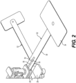
- the connector thus secures the portable electronic device to the work surface while permitting the portable electronic device to pivot with respect to the locking assembly while locked thereto.
- the second connector end is intended to be connected to the portable electronic device which a user desires to secure or lock to the locking assembly and the first connector end can be quickly locked and unlocked from the locking assembly for quick and efficient use.
- the locking assembly includes a clamp assembly having an elongated bar extending between a first end and a second end and a first jaw and a second jaw, with at least one of the first jaw or the second jaw moveable along the elongated bar between the first end and the second end for clamping a work surface between the first and second jaws.
- a locking mechanism is further included for selectively locking the relative positioning between the first jaw and the second jaw (i.e., securing the work surface between the first and second jaws in an un-movable/locked condition). Movement of the locking mechanism results in movement of the first jaw or the second jaw into forceful contact with the work surface.
- the clamp assembly can therefore be quickly and easily clamped to the work surface. Movement of the locking mechanism is pivotal and results in a leveraged lesser movement of the first jaw or second jaw for a stronger clamping force.
- Example embodiments will now be described more fully with reference to the accompanying drawings.
- the subject embodiments are directed to a locking assembly for securing portable electronic devices to a work surface.
- the example embodiments are only provided so that this disclosure will be thorough, and will fully convey the scope to those who are skilled in the art. Numerous specific details are set forth such as examples of specific components, devices, and methods, to provide a thorough understanding of embodiments of the present disclosure. It will be apparent to those skilled in the art that specific details need not be employed, that example embodiments may be embodied in many different forms within the scope of the appended claims and that neither should be construed to limit the scope of the disclosure. In some example embodiments, well-known processes, well-known device structures, and well-known technologies are not described in detail.
- the locking assembly is intended to provide a design that is hard to circumvent and is also compatible with a variety of portable electronic devices.
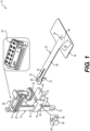
- the first jaw 14 extends from the elongated bar 18 to a first pad 25 disposed in a facing relationship with the second jaw 16.
- the first pad 25 connects to the first jaw 14 via a first pin 26 (as best illustrated in Figure 11 ) that allows the first pad 25 to pivot relative to the first jaw 14.
- the first pin 26 may allow pivotable or rotational movement between the first pad 25 and the first pin 26 with respect to at least one axis so that the first pad 25 remain parallel with the work surface if the locking assembly 10 is rocked back and forth.
- the first pin 26 may include a ball-type connection (not shown) allowing pivotable movement between the first pad 25 and the first pin 26 with respect to a plurality of axes.
- the second jaw 16 extends from the elongated bar 18 to a second pad 28 disposed in a facing relationship to the first jaw 14.
- the second pad 28 connects to the second jaw 16 via a second pin 30 that allows the second pad 28 to move relative to the second jaw 16.
- the second pin 30 may be parallel to the first pin 26.
- the second pin 30 may allow pivotable or rotational movement between the second pad 28 and the second pin 30 with respect to at least one axis so that the pads 25, 28 remain parallel with the work surface if the locking assembly 10 is rocked back and forth. It has been shown that maintaining the pads 25, 28 in a parallel position to the work surface can results in gripping forces of up to ten times as strong as non-parallel.
- the pads 25, 28 are preferable formed of rubber or other elastic materials that have a high friction index.
- the second pin 30 may include a ball-type connection (not shown) allowing pivotable movement between the second pad 28 and the second pin 30 with respect to a plurality of axes.
- the first jaw 14 and second jaw 16 move relative to one another along the elongated bar 18 on opposite sides of a work surface, such as a table, a counter, or the like.
- a locking mechanism 24 locks the first jaw 14 relative to the second jaw 16 once the pads 25, 28 have been positioned on and clamped to opposite sides of the work surface.
- the pads 25, 28 may be further configured to rotate with respect to the associated jaw 14, 16.
- first pin 26 and the second pin 30 illustrated in Figure 11 may be rotatable relative to the associated jaw 14, 16 and also pivotally connected to the pads 25, 28 along the at least one axis that may be perpendicular or parallel to the pins 26, 30.
- the pivotal and rotational movement of the pads 25, 28 result in a nullification of the leverage by a potential thief when wiggling and prying at the locking assembly 10 as the pads 25, 28 remain relatively stationary and flush during torqueing of the elongated bar 18 and/or jaws 14, 16.
- the connector 32 includes a connection plate 34 disposed adjacent the second connector end 44 and a connection strip 36 extending between the clamp assembly 12 from the first connector end 42 to the second connector end 44.
- the connection plate 34 is intended to be connected to the portable electronic device and the connection strip 36 is intended to be connected to the clamp assembly 12.
- the connection plate 34 and connection strip 36 may be integral or otherwise connected.
- the connection plate 34 and the connection strip 36 are preferably comprised of steel or other strong, semi-rigid materials.
- the connection strip 36 has a flat shape so that it is more rigid to deformation in certain directions, such as the directions in which it can pivot.
- connection plate 34 is steel and the laptop is plastic
- primer on the laptop results the laptop being harder to peel off by over ten times than those without primer.
- the layer of primer between the portable electronic device and the adhesive or double-sided tape significantly increases the bond strength.
- the portable electronic device is connected to the connection plate 34, the connection plate 34 connects to the connection strip 36, and the connection strip 36 connects to the clamp assembly 12.
- the first connector end 42 includes a first bore 46 for connection to the clamp assembly 12 and the second connector end 44 includes a second bore 48 ( Figure 7 ) for connection to the pivot connector 38, e.g., the rivet, that extends along an axis.
- the connection strip 36 and/or the connection plate 34 may be formed of steel and/or steel alloys.
- the first bore 46 of the connection strip 36 (as best shown in Figure 1 ) includes a slot 50 extending therefrom that allows for the connection of at least one add-on connector 52.
- the add-on connector 52 can be primarily the same as connection strips 36 except that the first bore 46 is replaced with a connection pin 54 that extends to a flange 56.
- the flange 56 is placed through the first bore 46 and the connection pin 54 is slid into the slot 50 such that it cannot be removed unless it is returned to the first bore 46.
- the first bore 46 becomes inaccessible such that the add-on connector 52 in the slot 50 cannot be removed.
- the elongated bar 18 may include a plurality of teeth 58 along an edge thereof.
- Each of the teeth 58 may be triangularly shaped and extend at opposite angles from the edge, for example 45°, such that adjacent teeth form 90° angles with one another.
- the second jaw 16 includes a cog 60 pivotally connected thereto via a pin 62.
- the cog 60 includes a detent 64 and a release trigger 66. As such, as the second jaw 16 is moved towards the first jaw 14, the detent 64 interfaces with the plurality of teeth 58, causing the cog 60 to pivot.
- the detent 64 cannot freely move along the teeth 58 as the second jaw 16 is moved away from the first jaw 14 so that it becomes locked unless the release trigger 66 is actuated to pivot the detent 64 away from the plurality of teeth 58.
- the cog 60 may be biased towards the plurality of teeth 58 by a torsion spring 61.
- pressure on the second jaw 16 may prevent use of the release trigger 66.
- Use of the release trigger 66 can become available again upon de-clamping via movement of the locking mechanism 24, which will be described in greater detail below.
- other methods of locking the first jaw 14 and the second jaw 16 may be adopted including methods that do not necessarily require teeth and instead rely on locking levers or screws as is known in the art.
- a bracket 78 connects the first pad 25 to the first jaw 14 and allows some pivotal movement of the first pad 25 with respect to the first jaw 14.
- the top surface 76 defines a depression 80 that is sized to at least partially receive the locking rod 72.
- actuation of the locking mechanism 24 causes the back plate 74 to move into and out of contact with the top surface 76 of the first pad 25 and the locking rod 72 to move into and out of the depression 80.
- the first bore 46 of the connection strip 36 can be aligned therewith so that the locking rod 72 extends through the first bore 46 before being locked against the top surface 76 and into the depression 80 to form another pivot connector parallel to the first. As such, the connector strip 36 become pivotally connected to the first jaw 14 and the locking mechanism 24.
- the locking mechanism 24 includes a linkage 82 that pivotally connects the locking mechanism 24 to the first jaw 14. More particularly, the locking mechanism 24 includes a lock housing 84 and a carriage 86, wherein the carriage 86 is connected to both the linkage 82 and the lock housing 84.
- the linkage 82 includes a first pivot connection 88 connected to the carriage 86 and a second pivot connection 90 connected to the locking rod 72, while the carriage 86 includes a lock pivot 92 that pivotally connects the carriage 86 to the first jaw 14.
- the linkage 82 allows the carriage 86 and lock housing 84 to move or pivot between a locked position and an unlocked position.
- Movement of the carriage 86 results in a leveraged lesser movement (which may be bending or flexing) of the first jaw 14 or second jaw 16 by a ratio of approximately 40:1. As such, the leveraged movement results in a tighter clamping force that can quickly be established.
- the lock housing 84 contains a deadbolt arrangement that includes a bolt 94 that is located near the elongated bar 18 and is permitted to slide out of and retract into the lock housing 84.
- the first jaw 14 further includes a bolt port 97 ( Figure 3 ) along the seat 68 and aligned to receive the bolt 94 in a locked position, preventing pivotal movement of the lock mechanism 24 and the corresponding release of the locking rod 72.
- a pair of carrier pins 96 are located on opposite sides of the bolt 94 and extend through carrier slots 98 in the lock housing 84.
- the carrier pins 96 can be manually slid along the carrier slots 98 to move the bolt 94 into and out of engagement with the bolt port 97.
- a spring 100 biases the bolt 94 in the locked position. Movement of the bolt 94 is guided by a guide block 102 that houses at least a portion of the bolt 94 and the pair of carrier pins 96.
- the first jaw 14 further includes a guide opening 104 ( Figure 5 ) for placement of the track block 106 that can be located therein.
- the guide block 102 includes a groove 103 that interfaces with the track block 106 and limits movement of the guide block 102 to only or substantially only axial movement.
- a lock tab 108 is pivotally connected to the lock housing 84 and is located near the guide block 102 and includes a lock surface 110.
- the lock tab 108 can be rotated such that the lock surface 110 blocks the return of the bolt 94 in a contact position, such that the bolt 94 is maintained in the locked position and cannot be retracted manually.
- the lock tab 108 can further be rotated to a non-contact position that permits the bolt 94 to be retracted.
- Rotational movement of the lock tab 108 can be effectuated by any number of means, however, in the illustrated embodiment it is effectuated by a motor 120.
- the lock mechanism 24 includes a user interface such as a keypad 112 with a plurality of keys that cover an upper portion of the lock housing 84.
- a printed circuit board (PCB) 114 is located beneath the keypad 112 and includes a lock assembly circuit 116 ( Figure 6 ) that will be described in greater detailed below, and which includes a plurality of switches 118 corresponding to the keys.
- the motor 120 is connected to the lock assembly circuit 116 and causes the lock tab 108 to pivot the locking surface 110 into and out of engagement with the guide block 102.
- One or more batteries 122 are located within the lock housing 94 and provide power to the lock assembly circuit 116 and the motor 120.
- the lock assembly circuit 116 may further include one or more lights, such as LEDs, to indicate the status of the lock tab 108 and/or bolt 94. For example, a green light 124 to indicate that the lock surface 110 of the lock tab 108 is not engaged with the guide block 102 and thus is free to retract. A red light 126 may also be included to indicate engagement of the lock tab 108, thus requiring a password input with the key pad 112.
- the keypad 112 may also include a lock/unlock button 128 and the lock assembly circuit 116 may further include a lock/unlock switch 130, such that the lock/unlock button 128 needs to be pressed before or after inputting the password to effectuate movement of the lock tab 108.
- the lock assembly circuit 116 is schematically illustrated in Figure 6 in accordance with one aspect of the disclosure.
- the various elements provided therein allow for a specific implementation. Thus, one of ordinary skill in the art of electronics and circuits may substitute various components to achieve a similar functionality.
- the lock assembly circuit 116 includes a General Computing Unit "GCU" system 132, a first user interface system 134 (corresponding to the keypad 112), a second user interface system 136, and an alarm circuit 138.
- GCU General Computing Unit
- certain operations of the lock assembly circuit 116 can be controlled via communication between the first user interface 134 and the GCU system 132.
- the GCU system 132 includes a controller 140 and a communications module 142.
- the controller 140 includes a processor 144 and a memory 146 having machine readable non-transitory storage.
- Programs and/or software 148 (such as iOS IDE, Windows, Linux, Android, iOS) may be saved on the memory 146 and so is an input data 150 obtained via the first user interface 134 and/or the second user interface system 136.
- Profile data 152 related to saved user preferences, such as passwords (password data) are also saved on the memory 146.
- the processor 144 translates and carries out instructions based on the software 148, input data 150, and profile data 152 and causes the motor 120 to move the lock tab 108 between positions.
- the communications module 142 may provide a wireless connection (such as Wi-Fi or Bluetooth) from the GCU system 132 to the second user interface system 136, which may include a portable electronic device.
- the communications module 142 may pair to a laptop and/or cellphone being secured to the locking mechanism 24.
- the processor may cause a notification to be sent to the cellphone in the event of movement, unlocking, and/or breaking.
- the alarm circuit 138 is configured to provide an auditory or other sensory alarm in the event of movement, unlocking, and/or breaking of the locking assembly 10.
- the alarm circuit 138 may include a piezo-type buzzer 156 (sensory alarm) for providing an auditory alert, a potentiometer 158, an accelerometer 160, and/or other movement detectors 162.
- connection strip 36 includes a first conductive layer 164 spaced from a second conductive layer 166 by an insulator 168 (as best illustrated in Figure 7B ).
- a contact 167 extends from the first conductive layer 164 and contacts the second conductive layer 164 to complete a circuit loop.
- the first conductive layer 164 is pivotally connected to the connection plate 34 and the second conductive layer 166 is spaced from the pivot connection. As such, when the connection strip 36 flexes up or down or is twisted along its length, the contact 167 becomes spaced from the first conductive layer 164, cutting the circuit loop, and the alarm circuit 138 is caused to initiate the alarm.
- the potentiometer 158 is located within the lock housing 84 and includes a pair of electrical contacts 170 that contact one another on the connection strip 36.
- the pair of electrical contacts 170 may include a first contact (170A) that extends from the alarm circuit 138 and is fixed to the connection strip 36 and a second contact (170B) that extends from the potentiometer 158 and electrically connects to the first contact when the connection strip 36 is in specific positions. As such, as the connection strip 36 is moved, the electric connection between the pair of electrical contacts 170 is broken, initiating the alarm circuit 138.
- FIG. 9 Another example implementation of the alarm circuit 138 is shown in Figure 9 , in which wherein the potentiometer 158 is located on or near the rivet 38 that pivotally connects the connection plate 34 to the connection strip 36. As such, a predetermined amount of rotation or pivoting of the connection plate 34 with respect to the connection strip 36 initiates the alarm circuit 138.
- FIG. 10 Yet another implementation of the alarm circuit 138 is illustrated in Figure 10 , in which the movement detector 162 includes a rotary-type detector 172 that contacts a center of the connection strip 36 and/or connected work surface and signals to the alarm circuit 138 after a predetermined distance of rotation.
- the movement detector 162 includes a rotary-type detector 172 that contacts a center of the connection strip 36 and/or connected work surface and signals to the alarm circuit 138 after a predetermined distance of rotation.
- the implementations of the alarm circuit illustrated 138 in Figures 7 through 10 are provided for the purpose of example and are not meant to be limiting. Each of the implementations may be used together or separate.
- the initiation of the alarm circuit 138 may be caused by certain instructions saved in memory 146 and executed by processor 144.
- the instructions saved in memory 146 may only allow the processor to cause the alarm circuit 138 to initiate once the password has been entered and the locking assembly 10 is in the locked position.
- any predetermined distances or threshold values may be saved on memory 146.
- the input data 150 obtained via the first user interface 134 and/or the second user interface system 136 may allow a user to alter predetermined thresholds and/or which of the various alarm implementations in Figures 7 through 10 are to be turned on or off.
- connection key 176 a modified connection plate, i.e., a connection key 176, that may be used in conjunction with or independently of the previously described connection strip 36.
- the portable electronic device includes a keyway 178, such as a Kensington slot, and the connection key 176 can be locked therein.
- the connection key 176 may be a cable or metal strip and include one of the previously described connection pins 54 to be located in the slot 50 of the connection strip 36.
- the connection key 176 may include the previously described pivot connector 38, e.g., rivet, for permanent connection to the connection strip 36. Removal of the connection key 176 may be via an electronic lock, mechanical lock, or other mechanisms as described herein.
- FIGS 13A and 13B illustrates a fourth embodiment of the locking assembly 10 which may include all of the features provided in the previous embodiments.
- the fourth embodiment further includes a modified connection plate, i.e., a connection bracket 180, which includes a plurality of adjustable clamps 182 connected to one another via a band 184.
- the adjustable clamps 182 can be secured around various locations of the portable electronic device and connected to each other via the band 184, which can be connected to the connection strip 36.
- Elastic buffers 186 may be connected to each adjustable clamp 182 for an improved connection that prevents scratching to the portable electronic device.
- Bolts 183 may be located on the adjustable clamps 182 for further tightening the elastic buffers 186 against the portable electronic device.
- the band 184 may be a metal cable and a tightening arm 185 is connected to the band 184 and pivotally connected to the first jaw 14 or second jaw 16 so that as it pivots it tightens the band 184, whereafter it can be locked against the first jaw 14 or second jaw 16 until the cable needs to be released.
- the tightening arm 185 may include an opening 189 for receiving the rivet 38 on the connection strip 36.
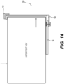
- Figure 14 illustrates a fifth embodiment of the locking assembly 10, which may include all of the features provided in the previous embodiments.
- the fifth embodiment further includes a modified connection plate, i.e., a corner clamp 188, which includes a pair of corner jaws 190 for mounting to vertically offset corners of a laptop or other portable electronic devices.
- the clamp 188 may further include one of the previously described connection pins 54 to be located in the slot 50 of the connection strip 36.
- the corner clamp 188 may include the previously described pivot connector 38, e.g., rivet, for permanent connection to the connection strip 36.
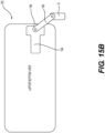
- FIGS 15A and 15B illustrate a sixth embodiment of the locking assembly 10, which may include all of the features provided in the previous embodiments.
- the sixth embodiment includes a smaller clamp assembly 12 and further includes a modified connection plate, i.e., a connection panel assembly 192, which includes a connection panel 194 for placement on the bottom of the portable electronic device that is pivotally connected to a side clamp 196 to clamp the panel 194 to the portable electronic device.
- a panel linkage 198 (best shown in Figure 15B ) extends between and pivotally connects to the panel 194 and pivotally connects to the clamp assembly 12.
Landscapes
- Engineering & Computer Science (AREA)
- Mechanical Engineering (AREA)
- General Engineering & Computer Science (AREA)
- Computer Hardware Design (AREA)
- Physics & Mathematics (AREA)
- General Physics & Mathematics (AREA)
- Details Of Connecting Devices For Male And Female Coupling (AREA)
- Casings For Electric Apparatus (AREA)
- Mounting Of Printed Circuit Boards And The Like (AREA)
Claims (14)
- Verriegelungsanordnung (10) zum Verriegeln eines tragbaren elektronischen Geräts an einer Arbeitsfläche, wobei die Verriegelungsanordnung umfasst:eine Klemmanordnung (12), die eine Stange (18) enthält, die sich zwischen einem ersten Ende (20) und einem zweiten Ende (22) erstreckt, um angrenzend an die Arbeitsfläche angeordnet zu sein;wobei die Klemmanordnung (12) ferner eine erste Klemmbacke (14) und eine zweite Klemmbacke (16) enthält, die sich von der Stange (18) in einem beabstandeten Verhältnis zueinander nach außen erstrecken;wenigstens eine von der ersten Klemmbacke (14) oder der zweiten Klemmbacke (16), die entlang der Stange (18) zwischen dem ersten und dem zweiten Ende beweglich ist, um eine Arbeitsfläche zwischen der ersten und der zweiten Klemmbacke einzuklemmen;einen Verriegelungsmechanismus (24), der bedienbar mit einer von der ersten Klemmbacke (14) oder der zweiten Klemmbacke (16) zwischenverbunden ist, und austauschbar von einem entriegelten Zustand, wobei die wenigstens eine bewegliche erste oder zweite Klemmbacke sich entlang der Stange (18) frei bewegen kann, zu einem verriegelten Zustand ist, wobei die wenigstens eine bewegliche erste oder zweite Klemmbacke daran gehindert wird, sich entlang der Stange (18) zu bewegen, um selektiv das relative Anordnen zwischen der ersten Klemmbacke (14) und der zweiten Klemmbacke (16) zu verriegeln; dadurch gekennzeichnet, dassein Verbinder (32) sich von einem ersten Verbinderende (42), das mit einer der Klemmanordnung (12) oder dem Verriegelungsmechanismus (24) in dem verriegelten Zustand lösbar verbunden ist, zu einem zweiten Verbinderende (44) zur Verbindung mit einem tragbaren elektronischen Gerät erstreckt, um das tragbare elektronische Gerät an der Arbeitsfläche, wenn der Verriegelungsmechanismus (24) in dem verriegelten Zustand angeordnet ist, zu befestigen.
- Verriegelungsanordnung (10) gemäß Anspruch 1, wobei
das erste Verbinderende (42) schwenkbar mit einem von der Klemmanordnung (12) oder dem Verriegelungsmechanismus (24) an einem ersten Schwenkverbinder um eine erste Achse schwenkbar verbunden ist, und wobei
das zweite Verbinderende (44) einen zweiten Schwenkverbinder zum schwenkbaren Verbinden des tragbaren elektronischen Geräts um eine zweite Achse enthält. - Verriegelungsanordnung (10) gemäß Anspruch 2, wobei die erste Achse zu der zweiten Achse parallel ist.
- Verriegelungsanordnung (10) gemäß Anspruch 3, wobei der Verbinder (32) einen Verbindungsstreifen (36) enthält, der sich zwischen dem ersten Verbinderende (42) und dem zweiten Verbinderende (44) erstreckt, und eine Verbindungsplatte (34) schwenkbar mit dem zweiten Verbinderende (44) um den zweiten Schwenkverbinder zum Herstellen der schwenkbaren Verbindung zwischen dem tragbaren elektronischen Gerät und dem Verbinder (32) verbunden ist.
- Verriegelungsanordnung (10) gemäß Anspruch 2, wobei sich die erste Klemmbacke (14) von der Stange zu dem ersten Pad (25) erstreckt, das sich in Richtung der zweiten Klemmbacke (16) erstreckt und dieser zugewandt ist, und die zweite Klemmbacke (16) sich von der Stange zu einem zweiten Pad (28) erstreckt, das sich in Richtung des ersten Pads (25) erstreckt und diesem zugewandt ist, und wobei ein erster Stift (26) das erste Pad (25) mit der ersten Klemmbacke (14) schwenkbar verbindet, und ein zweiter Stift (30) das zweite Pad (28) mit der zweiten Klemmbacke (16) schwenkbar verbindet, um eine Schwenkbewegung des ersten Pads (25) und des zweiten Pads (28) relativ zu deren jeweiligen ersten und zweiten Klemmbacken zu ermöglichen.
- Verriegelungsanordnung (10) gemäß Anspruch 1, wobei der Verbinder (32) ferner eine Verbindungsklammer (180) mit einer Vielzahl von anpassbaren Klemmen (182) zum Verbinden mit einer Vielzahl von verschiedenen Stellen des tragbaren elektronischen Geräts enthält.
- Verriegelungsanordnung (10) gemäß Anspruch 1, wobei die erste Klemmbacke (14) und die zweite Klemmbacke (16) in eine Position, die im Wesentlichen parallel zu der Stange (18) ist, faltbar sind.
- Verriegelungsanordnung (10) gemäß Anspruch 4, wobei die Verbindungsplatte (34) Klebestoff oder Doppelseitiges-Band zum Sichern des tragbaren elektronischen Geräts an die Verbindungsplatte enthält und wobei der zweite Schwenkverbinder aus einer Niete (38) zusammengesetzt ist, die eine Schwenkbewegung zwischen dem Verbindungsstreifen (36) und der Verbindungsplatte (34) ermöglicht.
- Verriegelungsanordnung (10) gemäß Anspruch 1, die ferner eine Leitspindel (202), die sich in der Stange (18) befindet und einen Leitspindelmotor (204) zum Drehen der Leitspindel (202) enthält, wobei Drehung der Leitspindel durch den Leitspindelmotor wenigstens eine von der ersten Klemmbacke (14) und der zweiten Klemmbacke (16) bewegt.
- Verriegelungsanordnung (10) gemäß Anspruch 1, wobei die erste Klemmbacke (14) ein erstes Pad (25) in einer zugewandten Beziehung mit der zweiten Klemmbacke (16) enthält, und die zweite Klemmbacke (16) ein Paar von zweiten Pads (28A, 28B) in einer zugewandten Beziehung mit der ersten Klemmbacke (14) enthält.
- Verriegelungsanordnung (10) gemäß Anspruch 1, wobei der Verbinder (32) einen Verbindungsschlüssel (176), der auf dem zweiten Verbinderende (44) angeordnet ist und einen Schlüsselweg (178) zum Verbinden des tragbaren elektronischen Geräts enthält, wobei der Schlüssel und der Schlüsselweg miteinander selektiv verriegelt werden können, um das tragbare elektronische Gerät an der Klemmanordnung (12) zu sichern.
- Verriegelungsanordnung (10) gemäß Anspruch 4, wobei das erste Pad (25) und das zweite Pad (28) jeweils drehbar relativ zu der jeweiligen einen der ersten Klemmbacke (14) und der zweiten Klemmbacke (16) sind.
- Verriegelungsanordnung (10) gemäß Anspruch 1, wobei der Verriegelungsmechanismus (24) schwenkbar mit der ersten Klemmbacke (14) über eine Kopplung verbunden ist und schwenkbar relativ zu der ersten Klemmbacke zwischen dem verriegelten und den entriegelten Zuständen ist
- Verriegelungsanordnung (10) gemäß Anspruch 13, ferner umfassend:die erste Klemmbacke (14), die ein erstes Pad (25) enthält, das in einer zugewandten Beziehung mit der zweiten Klemmbacke (16) angeordnet ist;die zweite Klemmbacke ein zweites Pad (28) enthält, das in einer zugewandten Beziehung mit der ersten Klemmbacke (14) angeordnet ist; undwobei der Verriegelungsmechanismus (24) in einer angrenzenden Beziehung mit dem ersten Pad (25) während des Übergangs von dem verriegelten Zustand in den entriegelten Zustand zum Erzwingen der ersten Klemmbacke (14) in eines zwingenden Kontakts mit der Arbeitsfläche und zum Herstellen einer Klemmkraft auf der Arbeitsfläche zwischen der ersten und der zweiten Klemmbacke.
Applications Claiming Priority (3)
| Application Number | Priority Date | Filing Date | Title |
|---|---|---|---|
| US201962871764P | 2019-07-09 | 2019-07-09 | |
| PCT/US2020/041374 WO2021007415A1 (en) | 2019-07-09 | 2020-07-09 | Locking assembly |
| EP20746518.8A EP3996874B1 (de) | 2019-07-09 | 2020-07-09 | Sperranordnung |
Related Parent Applications (2)
| Application Number | Title | Priority Date | Filing Date |
|---|---|---|---|
| EP20746518.8A Division-Into EP3996874B1 (de) | 2019-07-09 | 2020-07-09 | Sperranordnung |
| EP20746518.8A Division EP3996874B1 (de) | 2019-07-09 | 2020-07-09 | Sperranordnung |
Publications (4)
| Publication Number | Publication Date |
|---|---|
| EP4234166A2 EP4234166A2 (de) | 2023-08-30 |
| EP4234166A3 EP4234166A3 (de) | 2023-10-11 |
| EP4234166C0 EP4234166C0 (de) | 2025-01-29 |
| EP4234166B1 true EP4234166B1 (de) | 2025-01-29 |
Family
ID=74101752
Family Applications (2)
| Application Number | Title | Priority Date | Filing Date |
|---|---|---|---|
| EP20746518.8A Active EP3996874B1 (de) | 2019-07-09 | 2020-07-09 | Sperranordnung |
| EP23185750.9A Active EP4234166B1 (de) | 2019-07-09 | 2020-07-09 | Verriegelungsanordnung |
Family Applications Before (1)
| Application Number | Title | Priority Date | Filing Date |
|---|---|---|---|
| EP20746518.8A Active EP3996874B1 (de) | 2019-07-09 | 2020-07-09 | Sperranordnung |
Country Status (6)
| Country | Link |
|---|---|
| US (2) | US11105124B2 (de) |
| EP (2) | EP3996874B1 (de) |
| CN (1) | CN114072611B (de) |
| CA (1) | CA3146361A1 (de) |
| MX (1) | MX2022000348A (de) |
| WO (1) | WO2021007415A1 (de) |
Families Citing this family (2)
| Publication number | Priority date | Publication date | Assignee | Title |
|---|---|---|---|---|
| US11227073B2 (en) * | 2018-01-23 | 2022-01-18 | Niloy Roy | Anti-theft device |
| US11859413B2 (en) * | 2019-08-02 | 2024-01-02 | Meir Avganim | Security strip defining a security slot and attachable to mobile electronic devices |
Family Cites Families (23)
| Publication number | Priority date | Publication date | Assignee | Title |
|---|---|---|---|---|
| GB797362A (en) * | 1955-04-02 | 1958-07-02 | John Laverick | Improvements in holders for sacks, bags and the like |
| US4570465A (en) * | 1984-05-14 | 1986-02-18 | Bennett Anthony B | Plural branch locking cable |
| US4691907A (en) * | 1985-03-06 | 1987-09-08 | Yang Tai Her | C-clamp structure |
| FR2674563A1 (fr) * | 1991-03-29 | 1992-10-02 | Leber Jacques | Dispositif antivol pour appareil compact, du type micro-ordinateur ou imprimante par exemple. |
| DE4240003C2 (de) * | 1992-11-27 | 1997-11-20 | Herhof Umwelttechnik Gmbh | Schraubzwinge |
| US5595074A (en) | 1996-01-29 | 1997-01-21 | Munro; Robert G. | Desktop security locking station for a laptop computer or similarly sized computer peripheral |
| US5709110A (en) * | 1996-10-07 | 1998-01-20 | Greenfield; Jack | Security system for a lap-top computer |
| DE19731579A1 (de) * | 1997-07-23 | 1999-01-28 | Wolfcraft Gmbh | Spannwerkzeug, insbesondere Spannzwinge, Spannstock oder Spanntisch |
| US6192722B1 (en) * | 1999-05-11 | 2001-02-27 | Cnc Atlas Manufacturing Inc. | Anti-theft device for office equipment |
| US7499269B2 (en) | 2004-05-10 | 2009-03-03 | Peter Allen | Security clamp lock for notebook computer or other personal electronic device |
| US8837144B1 (en) | 2004-05-10 | 2014-09-16 | Think Products, Inc. | Locking assembly for electronic tablet and other devices |
| WO2007044096A2 (en) * | 2005-06-17 | 2007-04-19 | Peter Allen | Locks for personal electronic devices |
| US7293765B2 (en) * | 2005-07-07 | 2007-11-13 | Hooper Ronald L | Power vise |
| WO2010039984A2 (en) | 2008-10-01 | 2010-04-08 | Invue Security Products Inc. | Adjustable security device for laptop computer |
| US8882069B2 (en) * | 2010-01-29 | 2014-11-11 | ACCO Brands Corporation | Securing apparatus for portable electronic devices |
| US9103142B2 (en) | 2011-02-24 | 2015-08-11 | Invue Security Products Inc. | Merchandise display security tether including releasable adhesive |
| US9486897B2 (en) * | 2013-03-14 | 2016-11-08 | Kevin Trotsky | Foldable clamp for a mounting system |
| US9598883B1 (en) * | 2014-08-26 | 2017-03-21 | Alexander Gad AVGANIM | Security device for portable objects |
| WO2016149470A2 (en) * | 2015-03-17 | 2016-09-22 | Jeffery Cresina | External fixation system |
| JP6940530B2 (ja) * | 2016-06-30 | 2021-09-29 | イリノイ トゥール ワークス インコーポレイティド | 機器コンソールとしてのハードワイヤ接続されるタブレット/スマートフォン用のホルダー |
| CN206058429U (zh) * | 2016-09-19 | 2017-03-29 | 顾益 | 一种手机、平板防盗支架 |
| TWI766811B (zh) | 2017-06-06 | 2022-06-01 | 美商艾可布朗德斯公司 | 用於可攜式電子裝置的夾鉗鎖具 |
| CN109227163A (zh) * | 2018-11-20 | 2019-01-18 | 盐城市同俊精密机械制造有限公司 | 一种普通车床用c形多功能夹具 |
-
2020
- 2020-07-09 US US16/924,448 patent/US11105124B2/en active Active
- 2020-07-09 MX MX2022000348A patent/MX2022000348A/es unknown
- 2020-07-09 CN CN202080048617.4A patent/CN114072611B/zh active Active
- 2020-07-09 WO PCT/US2020/041374 patent/WO2021007415A1/en not_active Ceased
- 2020-07-09 EP EP20746518.8A patent/EP3996874B1/de active Active
- 2020-07-09 CA CA3146361A patent/CA3146361A1/en active Pending
- 2020-07-09 EP EP23185750.9A patent/EP4234166B1/de active Active
-
2021
- 2021-08-23 US US17/409,072 patent/US11846124B2/en active Active
Also Published As
| Publication number | Publication date |
|---|---|
| WO2021007415A1 (en) | 2021-01-14 |
| EP3996874B1 (de) | 2023-09-06 |
| US20210381283A1 (en) | 2021-12-09 |
| EP4234166A3 (de) | 2023-10-11 |
| CA3146361A1 (en) | 2021-01-14 |
| MX2022000348A (es) | 2022-04-26 |
| US11846124B2 (en) | 2023-12-19 |
| EP4234166A2 (de) | 2023-08-30 |
| EP4234166C0 (de) | 2025-01-29 |
| US11105124B2 (en) | 2021-08-31 |
| EP3996874C0 (de) | 2023-09-06 |
| CN114072611A (zh) | 2022-02-18 |
| CN114072611B (zh) | 2025-01-24 |
| US20210008691A1 (en) | 2021-01-14 |
| EP3996874A1 (de) | 2022-05-18 |
Similar Documents
| Publication | Publication Date | Title |
|---|---|---|
| CN110366714B (zh) | 用于便携式电子设备的底座 | |
| US11846124B2 (en) | Locking assembly | |
| US7439850B2 (en) | Keyless entry system | |
| EP1973313B1 (de) | Fahrzeughalterung für ein Mobiltelefon | |
| US4483420A (en) | Elevator door interlocking apparatus | |
| US20030224637A1 (en) | Plug socket securing device for use with plug socket having a slot formed by a resilient tab | |
| CN115552089B (zh) | 用于具有旋转展开臂的车辆开启部件的备用进入装置 | |
| EP3309652B1 (de) | Andockstation für elektronische vorrichtung | |
| US20230249504A1 (en) | Security Lock and Cover for Trailer Jacks | |
| WO2011090791A9 (en) | Plunger security lock and personal electronic device configured to be secured by the plunger lock | |
| CN102159785A (zh) | 手提物品之防窃装置 | |
| CN110593661B (zh) | 一种智能锁控制方法及应用其的智能锁 | |
| CN114482719B (zh) | 一种新型条锁 | |
| CN209896392U (zh) | 杠杆助力组件、连接器和车辆 | |
| CN101160440A (zh) | 插锁组件的毂锁装置 | |
| JP6980340B2 (ja) | 鎖錠構造 | |
| CN210743107U (zh) | 一种pos机安全监测装置 | |
| CN211598121U (zh) | 一种锁具及应用该锁具的箱包 | |
| CN215830218U (zh) | 智能识别门锁 | |
| JPH1173242A (ja) | 電子機器 | |
| CN218953043U (zh) | 一种执手换向门锁 | |
| CN216145940U (zh) | 一种具有智能锁扣的配电柜 | |
| CN116771200B (zh) | 一种电动锁体及门锁 | |
| JP2797275B2 (ja) | 確認スイッチ付き平面ハンドル装置 | |
| US20040217599A1 (en) | Handle mechanism for controlling a pivotal door of a vehicle |
Legal Events
| Date | Code | Title | Description |
|---|---|---|---|
| PUAI | Public reference made under article 153(3) epc to a published international application that has entered the european phase |
Free format text: ORIGINAL CODE: 0009012 |
|
| STAA | Information on the status of an ep patent application or granted ep patent |
Free format text: STATUS: THE APPLICATION HAS BEEN PUBLISHED |
|
| AC | Divisional application: reference to earlier application |
Ref document number: 3996874 Country of ref document: EP Kind code of ref document: P |
|
| AK | Designated contracting states |
Kind code of ref document: A2 Designated state(s): AL AT BE BG CH CY CZ DE DK EE ES FI FR GB GR HR HU IE IS IT LI LT LU LV MC MK MT NL NO PL PT RO RS SE SI SK SM TR |
|
| REG | Reference to a national code |
Ref country code: DE Ref legal event code: R079 Free format text: PREVIOUS MAIN CLASS: B25B0005160000 Ipc: B25B0005100000 Ref country code: DE Ref legal event code: R079 Ref document number: 602020045714 Country of ref document: DE Free format text: PREVIOUS MAIN CLASS: B25B0005160000 Ipc: B25B0005100000 |
|
| PUAL | Search report despatched |
Free format text: ORIGINAL CODE: 0009013 |
|
| AK | Designated contracting states |
Kind code of ref document: A3 Designated state(s): AL AT BE BG CH CY CZ DE DK EE ES FI FR GB GR HR HU IE IS IT LI LT LU LV MC MK MT NL NO PL PT RO RS SE SI SK SM TR |
|
| RIC1 | Information provided on ipc code assigned before grant |
Ipc: B25B 5/16 20060101ALI20230901BHEP Ipc: B25B 5/10 20060101AFI20230901BHEP |
|
| STAA | Information on the status of an ep patent application or granted ep patent |
Free format text: STATUS: REQUEST FOR EXAMINATION WAS MADE |
|
| 17P | Request for examination filed |
Effective date: 20240228 |
|
| RBV | Designated contracting states (corrected) |
Designated state(s): AL AT BE BG CH CY CZ DE DK EE ES FI FR GB GR HR HU IE IS IT LI LT LU LV MC MK MT NL NO PL PT RO RS SE SI SK SM TR |
|
| GRAP | Despatch of communication of intention to grant a patent |
Free format text: ORIGINAL CODE: EPIDOSNIGR1 |
|
| STAA | Information on the status of an ep patent application or granted ep patent |
Free format text: STATUS: GRANT OF PATENT IS INTENDED |
|
| INTG | Intention to grant announced |
Effective date: 20240905 |
|
| GRAS | Grant fee paid |
Free format text: ORIGINAL CODE: EPIDOSNIGR3 |
|
| GRAA | (expected) grant |
Free format text: ORIGINAL CODE: 0009210 |
|
| STAA | Information on the status of an ep patent application or granted ep patent |
Free format text: STATUS: THE PATENT HAS BEEN GRANTED |
|
| AC | Divisional application: reference to earlier application |
Ref document number: 3996874 Country of ref document: EP Kind code of ref document: P |
|
| AK | Designated contracting states |
Kind code of ref document: B1 Designated state(s): AL AT BE BG CH CY CZ DE DK EE ES FI FR GB GR HR HU IE IS IT LI LT LU LV MC MK MT NL NO PL PT RO RS SE SI SK SM TR |
|
| REG | Reference to a national code |
Ref country code: GB Ref legal event code: FG4D |
|
| REG | Reference to a national code |
Ref country code: CH Ref legal event code: EP |
|
| REG | Reference to a national code |
Ref country code: DE Ref legal event code: R096 Ref document number: 602020045714 Country of ref document: DE |
|
| REG | Reference to a national code |
Ref country code: IE Ref legal event code: FG4D |
|
| U01 | Request for unitary effect filed |
Effective date: 20250131 |
|
| U07 | Unitary effect registered |
Designated state(s): AT BE BG DE DK EE FI FR IT LT LU LV MT NL PT RO SE SI Effective date: 20250207 |
|
| PG25 | Lapsed in a contracting state [announced via postgrant information from national office to epo] |
Ref country code: RS Free format text: LAPSE BECAUSE OF FAILURE TO SUBMIT A TRANSLATION OF THE DESCRIPTION OR TO PAY THE FEE WITHIN THE PRESCRIBED TIME-LIMIT Effective date: 20250429 |
|
| PG25 | Lapsed in a contracting state [announced via postgrant information from national office to epo] |
Ref country code: PL Free format text: LAPSE BECAUSE OF FAILURE TO SUBMIT A TRANSLATION OF THE DESCRIPTION OR TO PAY THE FEE WITHIN THE PRESCRIBED TIME-LIMIT Effective date: 20250129 |
|
| PG25 | Lapsed in a contracting state [announced via postgrant information from national office to epo] |
Ref country code: ES Free format text: LAPSE BECAUSE OF FAILURE TO SUBMIT A TRANSLATION OF THE DESCRIPTION OR TO PAY THE FEE WITHIN THE PRESCRIBED TIME-LIMIT Effective date: 20250129 |
|
| PG25 | Lapsed in a contracting state [announced via postgrant information from national office to epo] |
Ref country code: NO Free format text: LAPSE BECAUSE OF FAILURE TO SUBMIT A TRANSLATION OF THE DESCRIPTION OR TO PAY THE FEE WITHIN THE PRESCRIBED TIME-LIMIT Effective date: 20250429 Ref country code: IS Free format text: LAPSE BECAUSE OF FAILURE TO SUBMIT A TRANSLATION OF THE DESCRIPTION OR TO PAY THE FEE WITHIN THE PRESCRIBED TIME-LIMIT Effective date: 20250529 |
|
| PG25 | Lapsed in a contracting state [announced via postgrant information from national office to epo] |
Ref country code: HR Free format text: LAPSE BECAUSE OF FAILURE TO SUBMIT A TRANSLATION OF THE DESCRIPTION OR TO PAY THE FEE WITHIN THE PRESCRIBED TIME-LIMIT Effective date: 20250129 |
|
| PG25 | Lapsed in a contracting state [announced via postgrant information from national office to epo] |
Ref country code: GR Free format text: LAPSE BECAUSE OF FAILURE TO SUBMIT A TRANSLATION OF THE DESCRIPTION OR TO PAY THE FEE WITHIN THE PRESCRIBED TIME-LIMIT Effective date: 20250430 |
|
| PG25 | Lapsed in a contracting state [announced via postgrant information from national office to epo] |
Ref country code: SM Free format text: LAPSE BECAUSE OF FAILURE TO SUBMIT A TRANSLATION OF THE DESCRIPTION OR TO PAY THE FEE WITHIN THE PRESCRIBED TIME-LIMIT Effective date: 20250129 |
|
| PG25 | Lapsed in a contracting state [announced via postgrant information from national office to epo] |
Ref country code: CZ Free format text: LAPSE BECAUSE OF FAILURE TO SUBMIT A TRANSLATION OF THE DESCRIPTION OR TO PAY THE FEE WITHIN THE PRESCRIBED TIME-LIMIT Effective date: 20250129 |
|
| PG25 | Lapsed in a contracting state [announced via postgrant information from national office to epo] |
Ref country code: SK Free format text: LAPSE BECAUSE OF FAILURE TO SUBMIT A TRANSLATION OF THE DESCRIPTION OR TO PAY THE FEE WITHIN THE PRESCRIBED TIME-LIMIT Effective date: 20250129 |
|
| PLBE | No opposition filed within time limit |
Free format text: ORIGINAL CODE: 0009261 |
|
| STAA | Information on the status of an ep patent application or granted ep patent |
Free format text: STATUS: NO OPPOSITION FILED WITHIN TIME LIMIT |
|
| REG | Reference to a national code |
Ref country code: CH Ref legal event code: L10 Free format text: ST27 STATUS EVENT CODE: U-0-0-L10-L00 (AS PROVIDED BY THE NATIONAL OFFICE) Effective date: 20251210 |
|
| 26N | No opposition filed |
Effective date: 20251030 |
|
| U21 | Renewal fee for the european patent with unitary effect paid with additional fee |
Year of fee payment: 6 Effective date: 20260115 |
|
| REG | Reference to a national code |
Ref country code: CH Ref legal event code: H13 Free format text: ST27 STATUS EVENT CODE: U-0-0-H10-H13 (AS PROVIDED BY THE NATIONAL OFFICE) Effective date: 20260224 |
|
| GBPC | Gb: european patent ceased through non-payment of renewal fee |
Effective date: 20250709 |
|
| PG25 | Lapsed in a contracting state [announced via postgrant information from national office to epo] |
Ref country code: GB Free format text: LAPSE BECAUSE OF NON-PAYMENT OF DUE FEES Effective date: 20250709 |
|
| PG25 | Lapsed in a contracting state [announced via postgrant information from national office to epo] |
Ref country code: CH Free format text: LAPSE BECAUSE OF NON-PAYMENT OF DUE FEES Effective date: 20250731 |