EP4233698A2 - Catheterization method and apparatus - Google Patents
Catheterization method and apparatus Download PDFInfo
- Publication number
- EP4233698A2 EP4233698A2 EP23179594.9A EP23179594A EP4233698A2 EP 4233698 A2 EP4233698 A2 EP 4233698A2 EP 23179594 A EP23179594 A EP 23179594A EP 4233698 A2 EP4233698 A2 EP 4233698A2
- Authority
- EP
- European Patent Office
- Prior art keywords
- catheter
- pressure sensor
- lumen
- valve
- coupler
- Prior art date
- Legal status (The legal status is an assumption and is not a legal conclusion. Google has not performed a legal analysis and makes no representation as to the accuracy of the status listed.)
- Granted
Links
Images
















Classifications
-
- A—HUMAN NECESSITIES
- A61—MEDICAL OR VETERINARY SCIENCE; HYGIENE
- A61B—DIAGNOSIS; SURGERY; IDENTIFICATION
- A61B5/00—Measuring for diagnostic purposes; Identification of persons
- A61B5/02—Detecting, measuring or recording for evaluating the cardiovascular system, e.g. pulse, heart rate, blood pressure or blood flow
- A61B5/021—Measuring pressure in heart or blood vessels
- A61B5/0215—Measuring pressure in heart or blood vessels by means inserted into the body
-
- A—HUMAN NECESSITIES
- A61—MEDICAL OR VETERINARY SCIENCE; HYGIENE
- A61F—FILTERS IMPLANTABLE INTO BLOOD VESSELS; PROSTHESES; DEVICES PROVIDING PATENCY TO, OR PREVENTING COLLAPSING OF, TUBULAR STRUCTURES OF THE BODY, e.g. STENTS; ORTHOPAEDIC, NURSING OR CONTRACEPTIVE DEVICES; FOMENTATION; TREATMENT OR PROTECTION OF EYES OR EARS; BANDAGES, DRESSINGS OR ABSORBENT PADS; FIRST-AID KITS
- A61F2/00—Filters implantable into blood vessels; Prostheses, i.e. artificial substitutes or replacements for parts of the body; Appliances for connecting them with the body; Devices providing patency to, or preventing collapsing of, tubular structures of the body, e.g. stents
- A61F2/02—Prostheses implantable into the body
- A61F2/24—Heart valves ; Vascular valves, e.g. venous valves; Heart implants, e.g. passive devices for improving the function of the native valve or the heart muscle; Transmyocardial revascularisation [TMR] devices; Valves implantable in the body
- A61F2/2427—Devices for manipulating or deploying heart valves during implantation
-
- A—HUMAN NECESSITIES
- A61—MEDICAL OR VETERINARY SCIENCE; HYGIENE
- A61B—DIAGNOSIS; SURGERY; IDENTIFICATION
- A61B17/00—Surgical instruments, devices or methods
- A61B17/00234—Surgical instruments, devices or methods for minimally invasive surgery
-
- A—HUMAN NECESSITIES
- A61—MEDICAL OR VETERINARY SCIENCE; HYGIENE
- A61B—DIAGNOSIS; SURGERY; IDENTIFICATION
- A61B5/00—Measuring for diagnostic purposes; Identification of persons
- A61B5/02—Detecting, measuring or recording for evaluating the cardiovascular system, e.g. pulse, heart rate, blood pressure or blood flow
- A61B5/021—Measuring pressure in heart or blood vessels
- A61B5/0215—Measuring pressure in heart or blood vessels by means inserted into the body
- A61B5/02158—Measuring pressure in heart or blood vessels by means inserted into the body provided with two or more sensor elements
-
- A—HUMAN NECESSITIES
- A61—MEDICAL OR VETERINARY SCIENCE; HYGIENE
- A61B—DIAGNOSIS; SURGERY; IDENTIFICATION
- A61B5/00—Measuring for diagnostic purposes; Identification of persons
- A61B5/145—Measuring characteristics of blood in vivo, e.g. gas concentration or pH-value ; Measuring characteristics of body fluids or tissues, e.g. interstitial fluid or cerebral tissue
- A61B5/14503—Measuring characteristics of blood in vivo, e.g. gas concentration or pH-value ; Measuring characteristics of body fluids or tissues, e.g. interstitial fluid or cerebral tissue invasive, e.g. introduced into the body by a catheter or needle or using implanted sensors
-
- A—HUMAN NECESSITIES
- A61—MEDICAL OR VETERINARY SCIENCE; HYGIENE
- A61B—DIAGNOSIS; SURGERY; IDENTIFICATION
- A61B5/00—Measuring for diagnostic purposes; Identification of persons
- A61B5/68—Arrangements of detecting, measuring or recording means, e.g. sensors, in relation to patient
- A61B5/6846—Arrangements of detecting, measuring or recording means, e.g. sensors, in relation to patient specially adapted to be brought in contact with an internal body part, i.e. invasive
- A61B5/6847—Arrangements of detecting, measuring or recording means, e.g. sensors, in relation to patient specially adapted to be brought in contact with an internal body part, i.e. invasive mounted on an invasive device
- A61B5/6852—Catheters
-
- A—HUMAN NECESSITIES
- A61—MEDICAL OR VETERINARY SCIENCE; HYGIENE
- A61B—DIAGNOSIS; SURGERY; IDENTIFICATION
- A61B5/00—Measuring for diagnostic purposes; Identification of persons
- A61B5/68—Arrangements of detecting, measuring or recording means, e.g. sensors, in relation to patient
- A61B5/6846—Arrangements of detecting, measuring or recording means, e.g. sensors, in relation to patient specially adapted to be brought in contact with an internal body part, i.e. invasive
- A61B5/6867—Arrangements of detecting, measuring or recording means, e.g. sensors, in relation to patient specially adapted to be brought in contact with an internal body part, i.e. invasive specially adapted to be attached or implanted in a specific body part
- A61B5/6869—Heart
-
- A—HUMAN NECESSITIES
- A61—MEDICAL OR VETERINARY SCIENCE; HYGIENE
- A61F—FILTERS IMPLANTABLE INTO BLOOD VESSELS; PROSTHESES; DEVICES PROVIDING PATENCY TO, OR PREVENTING COLLAPSING OF, TUBULAR STRUCTURES OF THE BODY, e.g. STENTS; ORTHOPAEDIC, NURSING OR CONTRACEPTIVE DEVICES; FOMENTATION; TREATMENT OR PROTECTION OF EYES OR EARS; BANDAGES, DRESSINGS OR ABSORBENT PADS; FIRST-AID KITS
- A61F2/00—Filters implantable into blood vessels; Prostheses, i.e. artificial substitutes or replacements for parts of the body; Appliances for connecting them with the body; Devices providing patency to, or preventing collapsing of, tubular structures of the body, e.g. stents
- A61F2/02—Prostheses implantable into the body
- A61F2/24—Heart valves ; Vascular valves, e.g. venous valves; Heart implants, e.g. passive devices for improving the function of the native valve or the heart muscle; Transmyocardial revascularisation [TMR] devices; Valves implantable in the body
- A61F2/2442—Annuloplasty rings or inserts for correcting the valve shape; Implants for improving the function of a native heart valve
- A61F2/2466—Delivery devices therefor
-
- A—HUMAN NECESSITIES
- A61—MEDICAL OR VETERINARY SCIENCE; HYGIENE
- A61M—DEVICES FOR INTRODUCING MEDIA INTO, OR ONTO, THE BODY; DEVICES FOR TRANSDUCING BODY MEDIA OR FOR TAKING MEDIA FROM THE BODY; DEVICES FOR PRODUCING OR ENDING SLEEP OR STUPOR
- A61M25/00—Catheters; Hollow probes
- A61M25/01—Introducing, guiding, advancing, emplacing or holding catheters
- A61M25/0105—Steering means as part of the catheter or advancing means; Markers for positioning
- A61M25/0133—Tip steering devices
-
- A—HUMAN NECESSITIES
- A61—MEDICAL OR VETERINARY SCIENCE; HYGIENE
- A61B—DIAGNOSIS; SURGERY; IDENTIFICATION
- A61B17/00—Surgical instruments, devices or methods
- A61B17/00234—Surgical instruments, devices or methods for minimally invasive surgery
- A61B2017/00238—Type of minimally invasive operation
- A61B2017/00243—Type of minimally invasive operation cardiac
-
- A—HUMAN NECESSITIES
- A61—MEDICAL OR VETERINARY SCIENCE; HYGIENE
- A61B—DIAGNOSIS; SURGERY; IDENTIFICATION
- A61B17/00—Surgical instruments, devices or methods
- A61B2017/00535—Surgical instruments, devices or methods pneumatically or hydraulically operated
- A61B2017/00561—Surgical instruments, devices or methods pneumatically or hydraulically operated creating a vacuum
-
- A—HUMAN NECESSITIES
- A61—MEDICAL OR VETERINARY SCIENCE; HYGIENE
- A61M—DEVICES FOR INTRODUCING MEDIA INTO, OR ONTO, THE BODY; DEVICES FOR TRANSDUCING BODY MEDIA OR FOR TAKING MEDIA FROM THE BODY; DEVICES FOR PRODUCING OR ENDING SLEEP OR STUPOR
- A61M25/00—Catheters; Hollow probes
- A61M2025/0001—Catheters; Hollow probes for pressure measurement
- A61M2025/0002—Catheters; Hollow probes for pressure measurement with a pressure sensor at the distal end
-
- A—HUMAN NECESSITIES
- A61—MEDICAL OR VETERINARY SCIENCE; HYGIENE
- A61M—DEVICES FOR INTRODUCING MEDIA INTO, OR ONTO, THE BODY; DEVICES FOR TRANSDUCING BODY MEDIA OR FOR TAKING MEDIA FROM THE BODY; DEVICES FOR PRODUCING OR ENDING SLEEP OR STUPOR
- A61M25/00—Catheters; Hollow probes
- A61M2025/0019—Cleaning catheters or the like, e.g. for reuse of the device, for avoiding replacement
-
- A—HUMAN NECESSITIES
- A61—MEDICAL OR VETERINARY SCIENCE; HYGIENE
- A61M—DEVICES FOR INTRODUCING MEDIA INTO, OR ONTO, THE BODY; DEVICES FOR TRANSDUCING BODY MEDIA OR FOR TAKING MEDIA FROM THE BODY; DEVICES FOR PRODUCING OR ENDING SLEEP OR STUPOR
- A61M25/00—Catheters; Hollow probes
- A61M25/0021—Catheters; Hollow probes characterised by the form of the tubing
- A61M25/0023—Catheters; Hollow probes characterised by the form of the tubing by the form of the lumen, e.g. cross-section, variable diameter
- A61M25/0026—Multi-lumen catheters with stationary elements
- A61M2025/0034—Multi-lumen catheters with stationary elements characterized by elements which are assembled, connected or fused, e.g. splittable tubes, outer sheaths creating lumina or separate cores
-
- A—HUMAN NECESSITIES
- A61—MEDICAL OR VETERINARY SCIENCE; HYGIENE
- A61M—DEVICES FOR INTRODUCING MEDIA INTO, OR ONTO, THE BODY; DEVICES FOR TRANSDUCING BODY MEDIA OR FOR TAKING MEDIA FROM THE BODY; DEVICES FOR PRODUCING OR ENDING SLEEP OR STUPOR
- A61M2230/00—Measuring parameters of the user
- A61M2230/04—Heartbeat characteristics, e.g. ECG, blood pressure modulation
Definitions
- the native heart valves i.e., the aortic, pulmonary, tricuspid, and mitral valves
- These heart valves can be damaged, and thus rendered less effective, by congenital malformations, inflammatory processes, infectious conditions, disease, etc. Such damage to the valves can result in serious cardiovascular compromise or death. Damaged valves can be surgically repaired or replaced during open heart surgery. However, open heart surgeries are highly invasive, and complications may occur. Transvascular techniques can be used to introduce and implant prosthetic devices in a manner that is much less invasive than open heart surgery.
- a transvascular technique useable for accessing the native mitral and aortic valves is the trans-septal technique.
- the trans-septal technique comprises advancing a catheter into the right atrium (e.g., inserting a catheter into the right femoral vein, up the inferior vena cava and into the right atrium). The septum is then punctured, and the catheter passed into the left atrium.
- a similar transvascular technique can be used to implant a prosthetic device within the tricuspid valve that begins similarly to the trans-septal technique but stops short of puncturing the septum and instead turns the delivery catheter toward the tricuspid valve in the right atrium. Being able to take pressure measurements from one or more surrounding chambers of the heart might provide information indicative of whether the implant is effective.
- a healthy heart has a generally conical shape that tapers to a lower apex.
- the heart is four-chambered and comprises the left atrium, right atrium, left ventricle, and right ventricle.
- the left and right sides of the heart are separated by a wall generally referred to as the septum.
- the native mitral valve of the human heart connects the left atrium to the left ventricle.
- the mitral valve has a very different anatomy than other native heart valves.
- the mitral valve includes an annulus portion, which is an annular portion of the native valve tissue surrounding the mitral valve orifice, and a pair of cusps, or leaflets, extending downward from the annulus into the left ventricle.
- the mitral valve annulus can form a "D"-shaped, oval, or otherwise out-of-round cross-sectional shape having major and minor axes.
- the anterior leaflet can be larger than the posterior leaflet, forming a generally "C"-shaped boundary between the abutting sides of the leaflets when they are closed together.
- the anterior leaflet and the posterior leaflet function together as a one-way valve to allow blood to flow only from the left atrium to the left ventricle.
- the left atrium receives oxygenated blood from the pulmonary veins.
- the muscles of the left atrium contract and the left ventricle dilates (also referred to as “ventricular diastole” or “diastole"), the oxygenated blood that is collected in the left atrium flows into the left ventricle.
- ventricular systole When the muscles of the left atrium relax and the muscles of the left ventricle contract (also referred to as “ventricular systole” or “systole"), the increased blood pressure in the left ventricle urges the sides of the two leaflets together, thereby closing the one-way mitral valve so that blood cannot flow back to the left atrium and is instead expelled out of the left ventricle through the aortic valve.
- chordae tendineae tether the leaflets to papillary muscles in the left ventricle.
- Mitral regurgitation involves the valve improperly allowing some blood to flow in the wrong direction through the valve.
- mitral regurgitation occurs when the native mitral valve fails to close properly and blood flows into the left atrium from the left ventricle during the systolic phase of heart contraction.
- Mitral regurgitation is one of the most common forms of valvular heart disease. Mitral regurgitation can have many different causes, such as leaflet prolapse, dysfunctional papillary muscles, stretching of the mitral valve annulus resulting from dilation of the left ventricle, more than one of these, etc.
- Mitral regurgitation at a central portion of the leaflets can be referred to as central jet mitral regurgitation and mitral regurgitation nearer to one commissure (i.e., location where the leaflets meet) of the leaflets can be referred to as eccentric jet mitral regurgitation.
- Central jet regurgitation occurs when the edges of the leaflets do not meet in the middle and thus the valve does not close, and regurgitation is present. Monitoring pressures in one or more chambers might provide helpful information during procedures to address valve issues.
- Catheterization methods and apparatuses are described herein. Some of the methods and apparatuses relate to catheter flushing and couplers for catheter flushing. Some of the methods and apparatuses relate to cardiac pressure measurement and catheter assemblies for cardiac pressure measurement.
- the treatment methods and steps shown and/or discussed herein can be performed on a living animal or on a simulation, such as on a cadaver, cadaver heart, simulator (e.g. with the body parts, heart, tissue, etc. being simulated), etc.
- a catheter coupler, flush section, or flush port includes a housing, a cap, and one or more seals.
- the housing has a catheter connection lumen, a plurality of passages, and an outer circumferential channel.
- the plurality of passages each connect the catheter connection lumen to the outer circumferential channel.
- the cap is rotatably coupled to the housing.
- the cap has an outlet port in fluid communication with the outer circumferential passage.
- the one or more seals provide seals between the housing and the cap that direct fluid flow from the outer circumferential passage to the outlet port.
- the cap is rotatable to position the outlet port a vertical orientation without rotating the housing.
- a method of flushing a catheter coupler comprises rotating a cap while keeping the position of a housing stationary.
- the cap rotates an outlet port to a top-dead-center position.
- a vacuum is applied to the outlet port to flush the catheter coupler.
- a delivery system includes a first catheter coupler, a second catheter coupler, a first catheter connected to the first catheter coupler, and a second catheter connected to the second catheter coupler.
- Each of the first and second catheter couplers have a housing, a cap, and one or more seals.
- the housings each have a catheter connection lumen, a plurality of passages, and an outer circumferential channel.
- the plurality of passages each connect the catheter connection lumen to the outer circumferential channel.
- the caps are each rotatably coupled to the housing.
- the cap has an outlet port in fluid communication with the outer circumferential passage.
- the one or more seals provide seals between the housing and the cap that direct fluid flow from the outer circumferential passage to the outlet port.
- Each cap is rotatable to position the outlet port in a vertical orientation without rotating the housing or the connected catheter.
- the second catheter extends through the first catheter coupler and the first catheter.
- a method of measuring a fluid pressure includes inserting a first catheter through a second catheter. A radially inwardly extending projection on an inside surface of the second catheter maintains a flow space between the first catheter and the second catheter. A pressure of the fluid in the flow space is measured.
- a catheter coupler, flush section, or flush port includes a catheter connection lumen, an outer circumferential passage, a plurality of connecting passages, and an outlet port.
- Each of the connecting passages connect the catheter connection lumen to the outer circumferential passage.
- the outlet port is in fluid communication with the outer circumferential passage.
- the outer circumferential passage and the plurality of connecting passages are sized such that when: 1) the outlet port is oriented in direction not vertically upwardly facing (e.g., a downwardly facing direction, etc.); 2) upper ones of the connecting passages contain air; and 3) lower ones of the connecting passages contain liquid, the air is drawn out of the outlet port.
- a delivery system includes a first catheter coupler, a second catheter coupler, a first catheter connected to the first catheter coupler, and a second catheter connected to the second catheter coupler.
- Each of the catheter couplers includes a catheter connection lumen, an outer circumferential passage, a plurality of connecting passages, and an outlet port.
- Each of the connecting passages of the couplers connect the catheter connection lumen to the outer circumferential passage.
- the outlet ports are each in fluid communication with the corresponding outer circumferential passage of the coupler.
- the outer circumferential passage and the plurality of connecting passages of each coupler are sized such that when: 1) the outlet port is oriented in a direction not vertically upwardly facing (e.g., a downwardly facing direction, etc.); 2) upper ones of the connecting passages contain air; and 3) lower ones of the connecting passages contain liquid, the air is drawn out of the outlet port.
- the second catheter extends through the first catheter coupler and the first catheter.
- a method of measuring pressure in a heart chamber includes inserting a valve implant or repair device delivery system into a left atrium.
- the valve implant or repair device delivery system includes a catheter, a pusher element, and a pressure sensor.
- the first catheter has a delivery lumen.
- the pusher element is positioned within the delivery lumen of the first catheter.
- the valve implant or repair device is detachably connected to the pusher element.
- the pressure sensor lumen is in at least one of the catheter and the pusher element.
- the pressure sensor and a fluid are disposed in the pressure sensor lumen.
- An open distal end of the pressure sensor lumen is exposed to the left atrium.
- a first blood pressure measurement is taken within the left atrium with the pressure sensor at a designated time during a cardiac cycle.
- This method can be performed on a living animal or on a simulation, such as on a cadaver, cadaver heart, simulator (e.g. with the body parts, heart, tissue, etc. being simulated), etc.
- a device for measuring pressure in a heart chamber using a valve implant or repair device delivery system includes a catheter, a pusher element, a pressure sensor lumen, and a pressure sensor.
- the catheter has a delivery lumen.
- the pusher element is positioned within the delivery lumen of the first catheter.
- the valve implant or repair device is detachably connected to the pusher element.
- the pressure sensor lumen is in at least one of the first catheter and the pusher element.
- the pressure sensor and a fluid are disposed in the pressure sensor lumen.
- the pressure sensor lumen comprises an open distal end.
- the delivery system uses the same components that are used to deliver the valve repair and/or replacement device to measure the pressure in the atrium (or other heart chamber).
- the delivery device and method can use a pressure sensor within and/or delivered through a catheter and/or pusher rod or tube system that is used to administer a heart valve therapy.
- the method includes inserting the delivery system into an atria of the heart, delivering the valve repair and/or replacement device to the native valve (such as the mitral valve, the tricuspid valve, the aortic valve, or the pulmonary valve) with the delivery system, and measuring the pressure with the pressure sensor through an opening in one of the catheters and/or pushers of the delivery system.
- the delivery system and method eliminates the need to introduce a separate catheter into the heart. For example, a lower atrial pressure in the left atrium at the position of the delivery device during ventricular systole indicates less regurgitation through the mitral valve. This lower pressure can indicate an effectively delivered mitral valve repair device (e.g. leaflet repair or modification device, annulus modification device, or chordae modification or replacement device) or replacement mitral valve implant.
- the disclosed delivery system and method does not require re-catheterization or other access of the left atrium to measure pressures.
- the disclosed delivery system and method also reduces the reliance on echo and other imaging to determine whether the valve therapy is effective.
- the delivery device for a replacement aortic valve can include the disclosed pressure measurement features.
- the valve repair therapy can be a replacement valve implant or a valve repair device.
- the atrial pressure can be in the right atrium or the left atrium.
- the delivery device can be configured to measure the pressure in a ventricle when the delivery device is positioned in the ventricle.
- the space can be within a catheter sheath, steering catheter, device delivery catheter, and/or pusher rod or tube.
- the space within catheters and/or pusher rod or tube can be within the main lumen of the catheter or pusher or can be within the wall of the catheter or pusher.
- the lumen can be reinforced with a pressure sensor catheter.
- the pressure sensor catheter can be a reinforcing sheath having its own lumen. Pressure can be measured with a pressure sensor.
- the pressure sensor can be an electric pressure sensor within a fluid-filled lumen or in fluid communication with the lumen.
- the fluid can be saline or another biocompatible fluid.
- a pressure sensor is placed in an optionally reinforced lumen or a port is provided for an off-the-shelf catheter to enter the body without having to re-catheterize the heart.
- the integration of the pressure sensor reduces movement and/or vibration of the pressure sensor to provide a more accurate pressure measurement. This more accurate measurement provides valuable data to the operator to determine efficacy of the device implanted.
- a lumen for an off-the-shelf pressure sensor within the main body of the delivery catheter (for example, a steerable catheter), the noise or vibration sensed by the pressure sensor that occurs in the heart chamber due to the flow of blood and the beating of the heart is reduced and a better indication of therapy efficacy can be obtained.
- the lumen for the pressure sensor can have an exit opening at the tip of the outer catheter, where the implant catheter exits. In another example embodiment, the lumen for the pressure sensor can exit at the tip of the steering catheter. In an example embodiment, the lumen can exit in a flexible section of a catheter that is positioned in the atrium when the catheter is in the heart and positioned towards a valve.
- a steerable catheter can be used in any of the example embodiments described herein. Other existing catheters can also be used.
- the pressure sensor can be connected to a monitoring system through either the flush port on the handle or a separate port on the handle designed for the introduction of a pressure sensor, and/or direct attachment of a pressure sensor.
- the pressure sensor can optionally be positioned external to the delivery device, such that it extends distally therefrom.
- the pressure sensor can be positioned so that a portion of the pressure sensor extends distally from an opening.
- the pressure sensor can be positioned within a lumen of the delivery device.
- the pressure monitoring device can be selected to accommodate normal positioning of a catheter, which typically includes but is not limited to, deflection, advancement, retraction, and/or rotation of the catheter.
- interconnection when one or more components are described as being connected, joined, affixed, coupled, attached, or otherwise interconnected, such interconnection may be direct as between the components or may be indirect such as through the use of one or more intermediary components.
- reference to a "member,” “component,” or “portion” shall not be limited to a single structural member, component, or element but can include an assembly of components, members, or elements.
- the terms “substantially” and “about” are defined as at least close to (and includes) a given value or state (preferably within 10% of, more preferably within 1% of, and most preferably within 0.1% of).
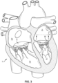
- FIGS 1 and 2 are cutaway views of the human heart H in diastolic and systolic phases, respectively.
- the right ventricle RV and left ventricle LV are separated from the right atrium RA and left atrium LA, respectively, by the tricuspid valve TV and mitral valve MV; i.e., the atrioventricular valves.
- the aortic valve AV separates the left ventricle LV from the ascending aorta AA
- the pulmonary valve PV separates the right ventricle from the pulmonary artery PA.
- Each of these valves has flexible leaflets (e.g., leaflets 20, 22 shown in Figures 4 and 5 ) extending inward across the respective orifices that come together or "coapt" in the flowstream to form the one-way, fluid-occluding surfaces.
- leaflets e.g., leaflets 20, 22 shown in Figures 4 and 5
- the methods, systems, devices, apparatuses, etc. herein are described primarily with respect to the mitral valve MV Therefore, anatomical structures of the left atrium LA and left ventricle LV will be explained in greater detail.
- the methods and apparatuses described herein can also be used in repairing other native valves, e.g., the devices can be used in repairing the tricuspid valve TV, the aortic valve AV, and the pulmonary valve PV Therefore, pressures in the right atrium RA and/or right ventricle RV can be measured in the same or a similar manner as the left atrium LA and/or the left ventricle LV.
- the left atrium LA receives oxygenated blood from the lungs.
- the blood that was previously collected in the left atrium LA moves through the mitral valve MV and into the left ventricle LV by expansion of the left ventricle LV.
- the left ventricle LV contracts to force the blood through the aortic valve AV and ascending aorta AA into the body.
- the leaflets of the mitral valve MV close to prevent the blood from regurgitating from the left ventricle LV and back into the left atrium LA, and blood is collected in the left atrium from the pulmonary vein PV
- the devices described by the present application are used to repair the function of a defective mitral valve MV That is, the devices are configured to help close the leaflets of the mitral valve to prevent blood from regurgitating from the left ventricle LV and back into the left atrium LA.
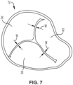
- the mitral valve MV includes two leaflets, the anterior leaflet 20 and the posterior leaflet 22.
- the mitral valve MV also includes an annulus 24, which is a variably dense fibrous ring of tissues that encircles the leaflets 20, 22.
- the mitral valve MV is anchored to the wall of the left ventricle LV by chordae tendineae 10.
- the chordae tendineae 10 are cord-like tendons that connect the papillary muscles 12 (i.e., the muscles located at the base of the chordae tendineae and within the walls of the left ventricle) to the leaflets 20, 22 of the mitral valve MV
- the papillary muscles 12 serve to limit the movements of the mitral valve MV and prevent the mitral valve from being reverted.
- the mitral valve MV opens and closes in response to pressure changes in the left atrium LA and the left ventricle LV.
- the papillary muscles do not open or close the mitral valve MV Rather, the papillary muscles brace the mitral valve MV against the high pressure needed to circulate blood throughout the body.
- the papillary muscles and the chordae tendineae are known as the subvalvular apparatus, which functions to keep the mitral valve MV from prolapsing into the left atrium LA when the mitral valve closes.
- Various disease processes can impair proper function of one or more of the native valves of the heart H.
- These disease processes include degenerative processes (e.g., Barlow's Disease, fibroelastic deficiency), inflammatory processes (e.g., Rheumatic Heart Disease), and infectious processes (e.g., endocarditis).
- degenerative processes e.g., Barlow's Disease, fibroelastic deficiency
- inflammatory processes e.g., Rheumatic Heart Disease
- infectious processes e.g., endocarditis
- damage to the left ventricle LV or the right ventricle RV from prior heart attacks i.e., myocardial infarction secondary to coronary artery disease
- other heart diseases e.g., cardiomyopathy
- valve stenosis occurs when a native valve does not open completely and thereby causes an obstruction of blood flow.
- valve stenosis results from buildup of calcified material on the leaflets of a valve, which causes the leaflets to thicken and impairs the ability of the valve to fully open to permit forward blood flow.
- valve regurgitation occurs when the leaflets of the valve do not close completely thereby causing blood to leak back into the prior chamber (e.g., causing blood to leak from the left ventricle to the left atrium).
- a native valve becomes regurgitant-or incompetent-which include Carpentier's type I, type II, and type III malfunctions.
- a Carpentier type I malfunction involves the dilation of the annulus such that normally functioning leaflets are distracted from each other and fail to form a tight seal (i.e., the leaflets do not coapt properly). Included in a type I mechanism malfunction are perforations of the leaflets, as are present in endocarditis.
- a Carpentier's type II malfunction involves prolapse of one or more leaflets of a native valve above a plane of coaptation.
- a Carpentier's type III malfunction involves restriction of the motion of one or more leaflets of a native valve such that the leaflets are abnormally constrained below the plane of the annulus.
- Leaflet restriction can be caused by rheumatic disease (Ma) or dilation of a ventricle (IIIb).
- a healthy mitral valve MV when a healthy mitral valve MV is in a closed position, the anterior leaflet 20 and the posterior leaflet 22 coapt, which prevents blood from leaking from the left ventricle LV to the left atrium LA.
- regurgitation occurs when the anterior leaflet 20 and/or the posterior leaflet 22 of the mitral valve MV is displaced into the left atrium LA during systole.
- This failure to coapt causes a gap 26 between the anterior leaflet 20 and the posterior leaflet 22, which allows blood to flow back into the left atrium LA from the left ventricle LV during systole.
- a leaflet e.g. leaflets 20, 22 of mitral valve MV
- may malfunction which can thereby lead to regurgitation.
- the mitral valve MV of a patient can have a wide gap 26 between the anterior leaflet 20 and the posterior leaflet 22 when the mitral valve is in a closed position (i.e., during the systolic phase).
- the gap 26 can have a width W between about 2.5 mm and about 17.5 mm, such as between about 5 mm and about 15 mm, such as between about 7.5 mm and about 12.5 mm, such as about 10 mm.
- the gap 26 can have a width W greater than 15 mm.
- a valve repair device is desired that is capable of engaging the anterior leaflet 20 and the posterior leaflet 22 to close the gap 26 and prevent regurgitation of blood through the mitral valve MV
- mitral valve regurgitation occurs, blood enters the left atrium from the left ventricle during systole. In a healthy heart, blood should only enter the left atrium from the pulmonary veins, not the left ventricle. The left atrial pressure then increases above the pressure it should be. For example, normal left atrial pressure can range from about 5 to about 15 mmHg. But when mitral valve regurgitation occurs, left atrial pressure could increase to a higher pressure, for example, 25 mmHg. With mitral valve regurgitation, the left atrial pressure is increased overall throughout the cardiac cycle and is most noticeable at the end of systole.
- stenosis or regurgitation can affect any valve
- stenosis is predominantly found to affect either the aortic valve AV or the pulmonary valve PV
- regurgitation is predominantly found to affect either the mitral valve MV or the tricuspid valve TV
- Both valve stenosis and valve regurgitation increase the workload of the heart H and may lead to very serious conditions if left un-treated; such as endocarditis, congestive heart failure, permanent heart damage, cardiac arrest, and ultimately death.
- the left side of the heart i.e., the left atrium LA, the left ventricle LV, the mitral valve MV, and the aortic valve AV
- the mitral valve MV or the aortic valve AV is particularly problematic and often life threatening. Accordingly, because of the substantially higher pressures on the left side of the heart, dysfunction of the mitral valve MV or the aortic valve AV is much more problematic.
- Malfunctioning native heart valves may either be repaired or replaced. Repair typically involves the preservation and correction of the patient's native valve. Replacement typically involves replacing the patient's native valve with a biological or mechanical substitute. Typically, the aortic valve AV and pulmonary valve PV are more prone to stenosis. Because stenotic damage sustained by the leaflets is irreversible, the most conventional treatments for a stenotic aortic valve or stenotic pulmonary valve are removal and replacement of the valve with a surgically implanted heart valve, or displacement of the valve with a transcatheter heart valve.
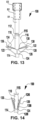
- FIG. 8-14 a schematically illustrated implantable prosthetic device 100 is shown in various stages of deployment.
- the prosthetic device 100 and associated systems, methods, etc. are described in more detail in International Application Nos. PCT/US2018/028189 and PCT/US2019/055320 , the disclosures of which are incorporated herein by reference in their entirety.
- the device 100 can include any other features for an implantable prosthetic device discussed in the present application, and the device 100 can be positioned to engage valve tissue (e.g., leaflets 20, 22) as part of any suitable valve repair system (e.g., any valve repair system disclosed in the present application).
- valve tissue e.g., leaflets 20, 22
- any suitable valve repair system e.g., any valve repair system disclosed in the present application.
- the device 100 is deployed and can include a coaptation portion or coaption portion 140 and an anchor portion 106.
- the device 100 can be deployed from a delivery sheath and/or can be deployed by a pusher tube or rod 81.
- the coaption portion 140 of the device 100 includes a coaption element 110 that is adapted to be implanted between the leaflets of the native valve (e.g., native mitral valve, native tricuspid valve, etc.) and is slidably attached to an actuation member or actuation element 112 (e.g., a wire, shaft, rod, line, suture, tether, etc.).
- an actuation member or actuation element 112 e.g., a wire, shaft, rod, line, suture, tether, etc.
- the anchor portion 106 is actuatable between open and closed conditions and can take a wide variety of forms, such as, for example, paddles, gripping elements, or the like. Actuation of the actuation element 112 opens and closes the anchor portion 106 of the device 100 to grasp the native valve leaflets during implantation.
- the actuation element 112 can take a wide variety of different forms. For example, the actuation element can be threaded such that rotation of the actuation element moves the anchor portion 106 relative to the coaption portion 140. Or, the actuation element may be unthreaded, such that pushing or pulling the actuation element 112 moves the anchor portion 106 relative to the coaption portion 140.
- the anchor portion 106 of the device 100 includes outer paddles 120 and inner paddles 122 that are connected between a cap 114 and the coaption element 110 by portions 124, 126, 128.
- the portions 124, 126, 128 can be jointed and/or flexible to move between all of the positions described below.
- the interconnection of the outer paddles 120, the inner paddles 122, the coaption element 110, and the cap 114 by the portions 124, 126, and 128 can constrain the device to the positions and movements illustrated herein.
- the actuation member or actuation element 112 extends through the delivery sheath and/or the pusher tube/rod and the coaption element 110 to the cap 114 at the distal connection of the anchor portion 106. Extending and retracting the actuation element 112 increases and decreases the spacing between the coaption element 110 and the cap 114, respectively.
- a collar 115 removably attaches the coaption element 110 to the pusher tube or rod 81 so that the actuation element 112 slides through the collar 115 and coaption element 110 during actuation to open and close the paddles 120, 122 of the anchor portion 106.
- a retrieval device can be used to connect to the collar 115 such that the actuation wire can extend through the collar 115 and the coaption element 110 to engage the anchor portion 106 to open the paddles 120, 122 and remove the device 100 from the valve tissue. Examples of retrieval devices that could be used are shown in PCT Application No. PCT/US2019/062391 filed November 20, 2019 , which is incorporated herein by reference in its entirety.
- the device 100 is shown in an elongated or fully open condition for deployment from the delivery sheath.
- the device 100 is loaded in the delivery sheath in the fully open position, because the fully open position takes up the least space and allows the smallest catheter to be used (or the largest implantable device 100 to be used for a given catheter size).
- the cap 114 is spaced apart from the coaption element 110 such that the paddles 120, 122 of the anchor portion 106 are fully extended.
- an angle formed between the interior of the outer and inner paddles 120, 122 is approximately 180 degrees.
- the barbed clasps 130 are kept in a closed condition during deployment through the delivery sheath 83 so that the barbs 136 ( Figs. 9 and 11 ) do not catch or damage the sheath or tissue in the patient's heart.
- the device 100 is shown in an elongated detangling condition, similar to Figure 8 , but with the barbed clasps 130 in a fully open position, ranging from about 140 degrees to about 200 degrees, such as about 170 degrees to about 190 degrees, or about 180 degrees between fixed and moveable portions of the barbed clasps 130.
- Fully opening the paddles 120, 122 and the clasps 130 has been found to improve ease of detanglement from anatomy of the patient during implantation of the device 100.
- the device 100 is shown in a shortened or fully closed condition.
- the compact size of the device 100 in the shortened condition allows for easier maneuvering and placement within the heart.
- the actuation member or actuation element 112 is retracted to pull the cap 114 towards the coaption element 110.
- the joints or flexible connections 126 between the outer paddle 120 and inner paddle 122 are constrained in movement such that compression forces acting on the outer paddle 120 from the cap 114 being retracted towards the coaption element 110 cause the paddles 120, 122 or gripping elements to move radially outward.
- the outer paddles 120 maintain an acute angle with the actuation element 112.
- the outer paddles 120 can optionally be biased toward a closed position.
- the inner paddles 122 during the same motion move through a considerably larger angle as they are oriented away from the coaption element 110 in the open condition and collapse along the sides of the coaption element 110 in the closed condition.
- the inner paddles 122 are thinner and/or narrower than the outer paddles 120, and the joint or flexible portions 126, 128 connected to the inner paddles 122 can be thinner and/or more flexible. For example, this increased flexibility can allow more movement than the joint or flexible portion 124 connecting the outer paddle 124 to the cap 114.
- the outer paddles 120 are narrower than the inner paddles 122.
- the joint or flexible portions 126, 128 connected to the inner paddles 122 can be more flexible, for example, to allow more movement than the joint or flexible portion 124 connecting the outer paddle 124 to the cap 114.
- the inner paddles 122 can be the same width or substantially the same width as the outer paddles.
- the device 100 is shown in a partially open, grasp-ready condition.
- the actuation member or actuation element 112 e.g., an actuation wire, actuation shaft, etc.
- the cap 114 is extended to push the cap 114 away from the coaption element 110, thereby pulling on the outer paddles 120, which in turn pulls on the inner paddles 122, causing the anchor portion 106 to partially unfold.
- the actuation lines 116 are also retracted to open the clasps 130 so that the leaflets can be grasped.
- the pair of inner and outer paddles 122, 120 are moved in unison, rather than independently, by a single actuation element 112.
- the positions of the clasps 130 are dependent on the positions of the paddles 122, 120.
- closing the paddles 122, 120 also closes the clasps.
- the paddles 120, 122 can be independently controllable.
- the device 100 can have two actuation elements and two independent caps, such that one independent wire and cap are used to control one paddle, and the other independent wire and cap are used to control the other paddle.
- one of the actuation lines 116 is extended to allow one of the clasps 130 to close.
- the other actuation line 116 is extended to allow the other clasp 130 to close. Either or both of the actuation lines 116 may be repeatedly actuated to repeatedly open and close the barbed clasps 130.
- the device 100 is shown in a fully closed and deployed condition.
- the pusher tube or rod 81 and actuation element 112 are retracted and the paddles 120, 122 and clasps 130 remain in a fully closed position.
- the device 100 can be maintained in the fully closed position with a mechanical latch or can be biased to remain closed through the use of spring materials, such as steel, other metals, plastics, composites, etc. or shape-memory alloys such as Nitinol.
- jointed or flexible portions 124, 126, 128, 138, and/or the inner and outer paddles 122, and/or an additional biasing component can be formed of metals such as steel or shape-memory alloy, such as Nitinol-produced in a wire, sheet, tubing, or laser sintered powder-and are biased to hold the outer paddles 120 closed around the coaption element 110 and the barbed clasps 130 pinched around native leaflets.
- the fixed and moveable arms 132, 134 of the barbed clasps 130 are biased to pinch the leaflets.
- the joint portions 124, 126, 128, 138, and/or the inner and outer paddles 122, and/or an additional biasing component can be formed of any other suitably elastic material, such as a metal or polymer material, to maintain the device in the closed condition after implantation.
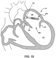
- the implantable device 100 of Figures 8-14 is shown being delivered and implanted within the native mitral valve MV of the heart H.
- the outer catheter or sheath 83 is inserted into the left atrium LA through the septum and the device 100 is deployed from the outer catheter in the fully open condition.
- the actuation element 112 is then retracted to move the device 100 into the fully closed condition shown in Figure 16 .
- the device 100 is moved into position within the mitral valve MV into the ventricle LV and partially opened so that the leaflets 20, 22 can be grasped.
- the steerable catheter 82 is extended out past the distal end of the outer catheter 83, and the pusher tube or rod 81 is extended out past the distal end of the steerable catheter.
- an actuation line 116 is extended to close one of the clasps 130, capturing a leaflet 20.
- Figure 19 shows the other actuation line 116 being then extended to close the other clasp 130, capturing the remaining leaflet 22.
- the pusher tube or rod 81 and actuation element 112 and actuation lines 116 are then retracted and the device 100 is fully closed and deployed in the native mitral valve MV
- FIGS 21A-21D schematics of various example embodiments of a delivery system 80 for delivering an implant into the heart are illustrated.
- the steerable catheter 82 and the outer catheter 83 each have a central lumen which can be considered a delivery lumen.
- FIG 21A a schematic of an example embodiment of a delivery system 80 for delivering an implant into the heart, is illustrated. This example embodiment is configured to have a pressure sensor within one of the delivery device's catheters or pusher.
- the delivery system 80 can include an implant delivering pusher tube or rod 81, a steerable catheter 82, and an outer catheter or sleeve 83.
- the steerable catheter 82 can extend out from the outer catheter's distal end 87, and the pusher tube or rod can extend outward from the steerable catheter's distal end 85.
- a valve implant, valve repair device, or other therapy is pushed out an end 85 of the steerable catheter 82 by a distal end 86 of the pusher tube or rod 81.
- the valve repair device or other therapy is initially positioned distally from the end 85 of the steerable catheter, inside the outer catheter 83 (i.e. not inside the steerable catheter). This allows the device to have a larger size, because it does not need to fit inside the steerable catheter 82.
- a pressure sensor P can be disposed in a lumen within the wall of any of the steerable catheter 82, the outer sleeve or catheter 83, the pusher tube or rod 81, the actuation rod 112, or in a separate catheter disposed in a space between any two of the steerable catheter 82, the outer sleeve or catheter 83, the pusher tube or rod 81, and the actuation rod 112.
- a pressure sensor lumen 88 can run along the length of the steerable catheter 82.
- the pressure sensor lumen 88 can be formed in the steerable catheter or can be a lumen of a separate catheter disposed in the steerable catheter.
- the open distal end 89 of the lumen 88 can be along the length of the steerable catheter (i.e. not at the end 85 of the steerable catheter).
- the pressure sensor P can be at the port 89 to directly measure pressure of the blood.
- Reference character P' represents another example embodiment where the pressure sensor P' is upstream of the port 89, such that the pressure of the blood in the heart is measured indirectly through fluid in the pressure sensor lumen 88.
- the pressure sensor port 89 can be anywhere along the catheter in a location that is typically positioned in an atrium of the heart during a valve treatment procedure.
- FIG. 21B another example embodiment of a delivery system 80 for measuring intra-atrial pressure during delivery of a heart valve implant or repair without requiring a separately introduced catheter is depicted.
- the example embodiment of Figure 21B is similar to Figure 21A , except that the open distal end or pressure port 89 for the pressure monitoring lumen 88 is at the distal end 85 of the steerable catheter 82.
- the pressure sensor P is positioned at the port 89 to directly measure the pressure of the blood.
- FIG. 21C another example embodiment of a delivery system 80 for measuring intra-atrial pressure during delivery of a heart valve implant or repair without requiring a separately introduced catheter is depicted.
- the pressure sensor lumen 88 is optionally embedded in the wall of the steerable catheter 82.
- the pressure sensor P is located proximal to the port 89 of the pressure sensor lumen.
- the pressure sensor can be at the port 89 of the steerable catheter as mentioned above.
- the pressure sensor lumen 88 can be embedded in the wall or disposed inside of the pusher rod or tube 81 and can have an open distal end or port 89 at the distal end of the pusher tube or rod.
- the opening or port 89 can be at any location along the pusher tube or rod 81 that extends from the steerable catheter 82.
- the pressure sensor lumen can be fully embedded within a wall of the steerable catheter or pusher tube or rod, or it can be partially embedded in the wall and protrude toward a center of the catheter's lumen.
- the lumens described herein can be defined by another catheter, which can be a pressure monitoring catheter, extending inside a lumen in the pusher 81.
- a pressure measuring catheter with a lumen is in the space between the steerable catheter and pusher tube 81.
- the pressure measuring catheter can optionally be fixed to the interior wall of the steerable catheter.
- the pressure sensor is positioned at the port 89.
- the pressure sensor P is positioned upstream of the port.
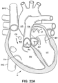
- FIG. 22A and 22B a cutaway view of the human heart H is illustrated in diastole and systole, respectively.
- a delivery system 80 with a pressure sensor P within it.
- the pressure sensor can record a pressure in the left atrium during diastole, and another pressure in the left atrium during systole.
- the pressure sensor is not limited to measuring pressure in the left atrium and can also be used in the right atrium or one of the ventricles.
- Figures 8-20 illustrate an example of one of the many different types of valve therapies that can be delivered by the delivery system 80. The valve therapy is not shown in Figures 22A and 22B to simplify these two figures.
- a typical valve therapy comprises positioning and/or deploying a valve implant or valve repair device (see Figures 8-20 ) in the native valve of the heart, which can be the mitral valve or the tricuspid valve.
- the valve therapy is not limited to a replacement valve or a valve repair device; it can also be a docking coil with a valve implant, sutures or chordae replacement devices, annuloplasty devices, and/or other implants used to correct the function of a heart native valve.
- the delivery system can use a transvascular technique such as a trans-septal technique, but is not limited thereto; the delivery system can be delivered to an atria of the heart by any presently known and future-developed technique.
- the pressure can be measured again to determine if a therapeutic effect has occurred, i.e., if a regurgitation or other heart valve defect has been repaired and/or improved.
- Figure 23A illustrates an end view, having an implant pusher or catheter 81, a steerable catheter 82, and an outer sheath 83.
- the steerable catheter can have an integrated lumen, typically used for steering cables (not shown) that extend along at least a length of the steerable catheter.
- an additional pressure sensor catheter 102 is positioned in the lumen 104 of the steerable catheter, adjacent to the interior surface of the steerable catheter wall.
- the pressure sensor catheter can have a lumen 105.
- the pressure sensor catheter 105 can have a pressure sensor in it ( Figures 23B-C ) or can be filled with a biocompatible fluid to measure the pressure ( Figure 23D ).
- the pressure sensor catheter shown here is not limited to this location but can be positioned anywhere in the space between the pusher tube and the steerable catheter, such that sufficient flexibility of the steerable catheter 82 and delivery system 80 as a whole can still be achieved so that the valve implant or repair device can be implanted in a desired location.
- Figure 23B illustrates a cross section of the delivery system 80 taken along line A-A.
- the opening at the end 86 of the pusher tube 81 for the actuation rod 112 (See Figure 10 ) is not shown, because the opening is offset from the cross-section plane A-A.
- a pressure sensor P is positioned inside a distal end of the pressure sensor catheter lumen 105 and connected to a communication link 103, such as a wire or pair of wires.
- the communication link 103 can extend out a proximal end (not shown, outside the patient) to allow the pressure sensed at the pressure sensor P to be monitored outside the patient by monitoring equipment.
- the pressure sensor P can be one of any of various pressure sensors.
- the pressure sensor can be a piezo-electric sensor, a pressure-sensing probe, or a barometric pressure sensor.
- the pressure sensor can be an electric pressure sensor that measures the pressure of fluid, which can be the blood in the left atrium of the heart or can be the pressure of the fluid, which can be a saline solution, in the pressure sensor lumen.
- the pressure sensor can be positioned to extend distally out of the end of the pressure sensor lumen 105 or the pressure sensor can be fully within the pressure lumen.
- the pressure sensor P can be positioned at any position along the length of the pressure sensor lumen 105.
- the pressure sensor P can be flush or substantially flush with the port 89 or the pressure sensor P can be spaced proximally away from the port inside the pressure sensor lumen.
- the pressure sensor lumen distal end or port 89 is flush with the distal end of the steerable catheter.
- the port 89 is spaced apart from the end of the steerable catheter.
- the pressure sensor can be embedded in the wall of the catheter having the pressure sensor lumen or pressure sensor catheter lumen.
- the pressure sensor catheter 102 can be fixedly connected to the interior wall of the steerable catheter by any means to secure catheter tubing together.
- the steerable catheter extends distally beyond the outer catheter 83.
- the pusher tube or rod extends even farther distally from the distal end of the steerable catheter.
- the pusher tube or rod can extend past the distal end of the steerable catheter so that it can reach through the mitral valve (or tricuspid valve) towards the left ventricle to allow an operator to properly position the valve implant or repair device during its deployment.
- the pressure sensor can provide accurate measurements of pressure in the atrium when the delivery system is inserted such that the steerable catheter is still in the atrium, and not at the valve annulus or below, in the ventricle.
- the pressure sensor P is located at the distal end of the lumen and can detect the pressure of the fluid within the lumen at the distal end of the lumen. Because the distal end of the lumen can be open, the pressure exerted by the fluid in the lumen on the sensor will be the same as the pressure of the blood in the left atrium, because the pressure of the blood in the left atrium will push on the fluid in the lumen.
- the pressure sensor By having the pressure sensor in a pressure sensor lumen that fits within existing space in the steerable catheter main lumen, the number of catheterizations of the heart needed to implant a valve device and record pressures to measure its efficacy is reduced, thereby reducing noise that could affect pressure measurements.
- FIG 23C a schematic of a cross section taken along line A-A of Figure 23A , of an example embodiment of a delivery system 80 with a pressure sensor is illustrated.
- the opening at the end 86 of the pusher tube 81 for the actuation rod 112 is not shown, because the opening is offset from the cross-section plane A-A.
- the pressure sensor is in accordance with an example embodiment.
- the pressure sensor is a fluid filled pressure sensor P located more proximal than that of Figure 23A .
- the pressure sensor catheter within the lumen of the steerable catheter is filled with a fluid.
- the fluid can be saline or another biocompatible fluid.
- this pressure sensor catheter is within a delivery system that is already inserted in the heart, an additional catheter is not required to be inserted to take a pressure measurement.
- the noise in the atrium is reduced by the separate lumen 102 and the pressure measurement can provide better feedback to the operator regarding the efficacy of the valve implant or repair being administered. Noise reduced is that which could otherwise be caused by movement, increased pressure, and additional disturbances to the blood flow in the left atrium, that could be caused by, for example, another catheter in the left atrium.
- FIG 23D a schematic of a cross-section taken along line A-A of Figure 23A , of another example embodiment of a delivery system 80 for measuring pressure in a heart chamber is illustrated.
- Figure 23D F the opening at the end 86 of the pusher tube 81 for the actuation rod 112 (See Figure 10 ) is not shown, because the opening is offset from the cross-section plane A-A.
- the pressure sensor catheter lumen 105 is filled with a fluid, which can be saline, and the pressure of the fluid is measured by a monitoring system.
- the monitoring system can be connected to the lumen 105 and/or fluid therein through either the flush port on the handle or a separate port on the handle designed for the introduction of a pressure sensor, as with the other example embodiments described herein.
- the pressure of the fluid in the lumen remains consistent throughout the lumen, and because the distal end of the lumen is open to the left atrium, the pressure exerted by the fluid in the lumen will be the same as the pressure of the blood in the left atrium.
- the pressure can be measured using fluid instead of a pressure sensor P in any of the example embodiments described herein.
- the pressure can be measured in the same way as it is measured with regard to the embodiment of Figure 23D .
- An example embodiment can be to have the pressure sensor P embedded in the wall of any catheter that surrounds a fluid filled lumen.
- the catheter wall can be that of the pusher tube or rod 81, the steerable catheter 82, the pressure sensor catheter 102, and/or the actuation rod 112 (See Figure 10 ).
- the fluid filled lumen can be the pressure catheter lumen 105 or the pressure sensor lumen 88.
- Figure 24A illustrates an end view, having a pusher tube or rod 81, a steerable catheter 82, and an outer sheath 83.
- an additional pressure sensor lumen 88 is integrated in the wall of the steerable catheter.
- the pressure sensor lumen can bump out into the central lumen 104 of the steerable catheter as shown in Figure 24A , or it can be flush within the wall of the steerable catheter.
- the integrated pressure sensor lumen can be adjacent to the integrated steerable catheter lumen as illustrated in Figure 24A , or it can be spaced apart from it.
- Figure 24B illustrates a cross section of the delivery system 80 taken along line B-B.
- the opening at the end 86 of the pusher tube 81 for the actuation rod 112 (See Figure 10 ) is not shown, because the opening is offset from the cross-section plane B-B.
- a pressure sensor P is positioned inside a distal end of the pressure sensor lumen 88 of the steerable catheter 82 and is held in place at least by a connecting link 103.
- the pressure sensor can be an electric pressure sensor (or other type of pressure sensor).
- the pressure sensor can be positioned to extend distally out of the end of the pressure sensor lumen 88 or it can be fully within the pressure lumen.
- the pressure sensor lumen distal end 89 can be flush with the distal end of the steerable catheter in this example embodiment but is not limited to such a length.
- the steerable catheter extends distally beyond the outer catheter 83.
- the pusher tube or rod extends even farther distally from the distal end of the steerable catheter. As the pusher tube or rod is what delivers a valve implant or repair device to the valve, it can be extendable from the end of the steerable catheter.
- the pusher tube or rod can extend past the distal end of the steerable catheter so that it can reach through the mitral valve (or tricuspid valve) towards the left ventricle to allow an operator to properly position the valve implant or valve repair device during its deployment.
- the pressure sensor can provide accurate measurements in the atrium when the delivery system is inserted such that the steerable catheter is still in the atrium, and not at the valve annulus or in the ventricle.
- FIG 24C a schematic of a cross section taken along line B-B of Figure 24A , of another example embodiment of a delivery system 80 with a pressure sensor is illustrated.
- the opening at the end 86 of the pusher tube 81 for the actuation rod 112 is not shown, because the opening is offset from the cross-section plane B-B.
- the pressure sensor is in accordance with another example embodiment.
- the pressure sensor is a fluid filled pressure sensor lumen, having a pressure sensor P at a more proximal location within the pressure sensor lumen, which is described in greater detail above.
- the lumen 104 of the steerable catheter is filled with a fluid, as described above.
- this example embodiment of a pressure sensor catheter is within a delivery system that is already implanted in the heart, an additional catheter is not required to be inserted to take a pressure measurement. Therefore, the noise in the atrium is reduced and the pressure measurement can provide better feedback to the operator regarding the efficacy of the valve implant or repair device being administered.
- Figure 25A illustrates an end view, having a pusher tube or rod 81, a steerable catheter 82, and an outer sheath 83.
- the steerable catheter can have an integrated lumen as described above.
- the steerable catheter can have another integrated lumen 88.
- an additional pressure sensor catheter 102 is positioned in the additional lumen 88 of the steerable catheter, adjacent to the interior surface of the steerable catheter wall.
- the pressure sensor catheter can have its own lumen 105.
- the pressure sensor lumen can bump out into the central lumen 104 of the steerable catheter as shown in Figure 25A , or it can be flush within the wall of the steerable catheter.
- the integrated pressure sensor lumen can be adjacent to the integrated steerable catheter lumen as illustrated in Figure 25A , or it can be spaced apart from it.
- the additional lumen within the steerable catheter shown in Figure 25A is not limited to the locations described herein but can be positioned anywhere at least partially embedded in the wall of the steerable catheter, such that sufficient flexibility of the steerable catheter and delivery system as a whole can still be achieved so that the valve therapy can be implanted in a desired location.
- Figure 25B illustrates a cross section of the delivery system 80 taken along line C-C.
- the opening at the end 86 of the pusher tube 81 for the actuation rod 112 (See Figure 10 ) is not shown, because the opening is offset from the cross-section plane C-C.
- a pressure sensor P is positioned inside a distal end of the pressure sensor lumen 105 and can be held in place by an optional connecting link 103.
- the pressure sensor can be an electric pressure sensor or other sensor.
- the pressure sensor can be positioned to extend distally out of the end of the pressure sensor catheter lumen 105 or it can be fully within the pressure lumen.
- the pressure sensor catheter lumen distal end 89 is flush with the distal end of the steerable catheter in this example embodiment but is not limited to such a length.
- the pressure sensor catheter 102 can be fixedly connected to the interior wall of the steerable catheter lumen 104 by any means to secure catheter tubing together.
- the pressure sensor catheter can be slidably positioned in the steerable catheter lumen 104.
- the steerable catheter extends distally beyond the outer catheter 83.
- the pusher tube or rod 86 extends even farther distally from the distal end of the steerable catheter. As the pusher tube or rod is what delivers a valve implant or repair to the valve, it can be extendable from the end of the steerable catheter.
- the pusher tube or rod can extend past the distal end of the steerable catheter so that it can reach through the mitral valve (towards the left ventricle) to allow an operator to properly position the valve implant or repair during its deployment.
- the pressure sensor can provide accurate measurements in the atrium when the delivery system is inserted such that the steerable catheter is still in the atrium, and not at the valve annulus or in the ventricle.
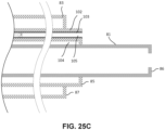
- FIG. 25C a schematic of a cross section taken along line C-C of Figure 25A , of another example embodiment of a delivery system 80 with a pressure sensor is illustrated.
- the opening at the end 86 of the pusher tube 81 for the actuation rod 112 (See Figure 10 ) is not shown, because the opening is offset from the cross-section plane C-C.
- the pressure sensor is a fluid filled pressure sensor lumen, having a pressure sensor P at a more proximal location within the pressure sensor lumen, which is described in greater detail above. Because this example embodiment of a pressure sensor catheter is within a delivery system that is already implanted in the heart, an additional catheter is not required to be inserted to take a pressure measurement. Therefore, the noise in the atrium is reduced and the pressure measurement can provide more reliable feedback to the operator regarding the efficacy of the valve implant or repair being administered.
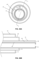
- Figure 26A illustrates an end view, having a pusher rod or tube 81, a steerable catheter 82, and an outer sheath 83.
- Figure 26B the opening at the end 86 of the pusher tube 81 for the actuation rod 112 (See Figure 10 ) is not shown, because the opening is offset from the cross-section plane C-C.
- an additional pressure sensor lumen 88 is integrated in the wall of the pusher rod or tube 81.
- the pressure sensor lumen can be flush within the wall of the pusher rod or tube 81 as shown in Figure 26A , or it can bump out into a central lumen of the pusher tube or rod 81.
- Figure 26B illustrates a cross section of the delivery system 80 taken along line D-D.
- a pressure sensor P is positioned inside a distal end of the pressure sensor lumen 88 of the pusher rod or tube 81 and can be held in place at least by a connecting link 103.
- the pressure sensor can be positioned extending distally out of the end of the pressure sensor lumen 88 or it can be fully within the pressure sensor lumen.
- the pressure sensor lumen can be filled with a biocompatible fluid such as saline.
- the pressure sensor lumen distal end 89 is flush with the distal end of the pusher rod or tube 81 in this example embodiment but is not limited to such a length.
- the steerable catheter extends distally beyond the outer catheter 83.
- the pusher tube or rod extends even farther distally from the distal end of the steerable catheter.
- the pusher tube or rod can be extendable from the end of the steerable catheter.
- the pusher tube or rod can extend past the distal end of the steerable catheter so that it can reach through the mitral valve (or tricuspid valve) towards the left ventricle to allow an operator to properly position the valve implant or repair during its deployment.
- the pressure sensor can measure an accurate atrial pressure when its opening to the exterior of the delivery system is located in the atrium.
- the pressure sensor can provide accurate measurements in the atrium when the delivery system is inserted such that the pusher tube or rod is still in the atrium, and not at the valve annulus or in the ventricle.
- the pressure sensor in a pressure sensor lumen integrated within the pusher rod or tube 81, the number of catheterizations of the heart needed to implant a valve implant or repair and record pressures to measure its efficacy is reduced, thereby reducing noise that could affect pressure measurements.
- FIG. 26C a schematic of a cross section taken along line D-D of Figure 26A , of another example embodiment of a delivery system 80 with a pressure sensor is illustrated.
- the opening at the end 86 of the pusher tube 81 for the actuation rod 112 is not shown, because the opening is offset from the cross-section plane C-C.
- the pressure sensor is in accordance with another example embodiment.
- the pressure sensor is a fluid filled pressure sensor lumen, having a pressure sensor P at a more proximal location within the pressure sensor lumen, which is described in greater detail above.
- this pressure sensor catheter is within a delivery system that is already implanted in the heart, an additional catheter is not required to be inserted to take a pressure measurement. Therefore, the noise in the atrium is reduced and the pressure measurement can provide better feedback to the operator regarding the efficacy of the valve implant or repair device.
- the pressure can be measured according to the following method.
- the pressure sensor can be an electric pressure sensor.
- the pressure sensor in Figure 23B is accessible to the left atrium because it is positioned at the distal end of the pressure sensor catheter which can be flush with the distal end of the steerable catheter, and the distal end of at least the pressure sensor catheter is open to the atrium.
- the pressure sensor can be connected to a monitoring system (not shown) through a flush port on the handle of the delivery system.
- the pressure sensor can be connected to a monitoring system through a separate port on the handle, where the separate port is for the introduction of the pressure sensor catheter or direct attachment of the pressure monitor.
- the pressure sensor in Figure 23B can be positioned in other locations, too.
- a baseline pressure measurement can be taken when the steerable catheter distal end 86 is in the left atrium, before the valve implant or repair device is delivered.
- the pressure of the fluid within the pressure sensor lumen can be electronically taken and can be recorded and/or displayed in the monitoring system. As explained above, this pressure is about the same or the same as the pressure in the left atrium of the heart.
- This baseline pressure measurement can be recorded during systole and/or diastole, and a measurement during and/or at the end of systole can be determinative of whether regurgitation is occurring.
- the valve implant or repair device can then be delivered, but before withdrawing the delivery system, the distal end of the steerable catheter can be positioned in the left atrium again, and another pressure measurement can be taken.
- This pressure measurement can determine whether the pressure has changed now that the valve implant or repair device has been positioned in the native valve.
- the pressure measurement should be taken at the same point(s) in the cardiac cycle (during systole and/or at the end of systole) as the baseline measurement.
- the pressure measurement taken(s) by the pressure sensor at this time should be lower than the baseline pressure measurement, due to correction of the regurgitation of blood back into the atrium.
- the pressure can be measured before the valve implant or repair device is disconnected from the delivery catheter, so that it can be repositioned if an operator so requires, to achieve effective placement. If a valve implant or repair is effectively implanted, the blood will flow from the left ventricle to the aorta instead of back through the mitral valve. The pressure can be measured as many times as needed. The pressure can also be measured continuously.
- the pressure sensor lumen can be filled with a fluid such as saline or other biocompatible fluid known by one of ordinary skill in the art to be used in fluid filled atrial pressure monitors.
- the pressure sensor P can be at a more proximal location along the length of the catheter delivery system.
- a baseline pressure measurement can be taken when the steerable catheter distal end 86 is in the left atrium, before the valve implant or repair device is delivered. This baseline pressure measurement can be recorded at any time, such as during or at the end of systole, as explained above.
- the valve implant or repair device can then be delivered, but before withdrawing the delivery system, the distal end of the steerable catheter can be positioned in the left atrium, and another pressure measurement can be taken.
- the pressure can be measured again to determine if it has changed now that the valve implant or repair device has been positioned in the native valve.
- the pressure measurement can be taken at the same point in the cardiac cycle as the baseline measurement.
- the pressure measurement taken by the pressure sensor at this time should be lower than the baseline pressure measurement, due to correction of the regurgitation of blood back into the atrium, which can cause a higher than normal pressure in the left atrium. Conversely, a higher pressure in the left atrium will result in a higher pressure in the fluid in the pressure sensor lumen.
- the pressure can be measured before the valve implant or repair device is disconnected from the pusher tube or rod, so that it can be repositioned to achieve effective placement. If a valve implant or repair device is effectively positioned, the blood will flow from the left ventricle to the aorta instead of back through the mitral valve. The pressure can be measured as many times as needed.
- This method can be performed on a living animal or on a simulation, such as on a cadaver, cadaver heart, simulator (e.g. with the body parts, heart, tissue, etc. being simulated), etc.
- the left atrial pressure can be measured in the same way that the pressure is measured for the embodiments having a pressure sensor P positioned within a fluid filled lumen described herein, such as the example embodiment of Figure 23C .
- the pressure sensor lumen can be filled with a fluid such as saline or other biocompatible fluid known by one of ordinary skill in the art to be used in fluid filled atrial pressure monitors.
- a baseline pressure measurement can be taken when the steerable catheter distal end 86 is in the left atrium, before the valve implant or repair device is delivered. This baseline pressure measurement can be recorded at any time by the monitoring system, such as during or at the end of systole, as explained above.
- the valve implant or repair device can then be delivered, but before withdrawing the delivery system, the distal end of the steerable catheter can be positioned in the left atrium, and another pressure measurement can be taken.
- the pressure can be measured again to determine if it has changed now that the valve implant or repair device has been positioned in the native valve.
- the pressure measurement can be taken at the same point in the cardiac cycle as the baseline measurement.
- the pressure measurement taken at this time should be lower than the baseline pressure measurement, due to correction of the regurgitation of blood back into the atrium, which can cause a higher than normal pressure in the left atrium.
- a higher pressure in the left atrium will result in a higher pressure in the fluid in the pressure sensor lumen.
- the pressure can be measured before the valve implant or repair device is disconnected from the pusher tube or rod, so that it can be repositioned to achieve effective placement.
- a valve implant or repair device If a valve implant or repair device is effectively positioned, the blood will flow from the left ventricle to the aorta instead of back through the mitral valve.
- the pressure can be measured as many times as needed.
- the left atrial pressure can be measured in this same way for any fluid-filled lumen embodiment without a pressure sensor P described herein.
- This method can be performed on a living animal or on a simulation, such as on a cadaver, cadaver heart, simulator (e.g. with the body parts, heart, tissue, etc. being simulated), etc.
- a method of measuring pressure in the left atrium can have the same steps as that described above with respect to Figures 23A-23C .
- the only difference is that in the embodiment of Figure 24B , instead of having a separate pressure sensor catheter lumen 102, there is an integrated pressure sensor lumen 88 in the wall of the steerable catheter 82.
- Figure 25B is similar to Figure 24B but has a pressure sensor catheter 102 with its own lumen 105 that extends along the lumen 88 of the steerable catheter.
- the method is similar to the example embodiments of the methods described above.
- the open distal end 89 of the pressure sensor lumen of the valve delivery catheter should be positioned in the left atrium to obtain a left atrium pressure.
- Measuring the pressure using an electronic pressure sensor P can use the following steps.
- the delivery system 80 is inserted through a trans-septal procedure, so that the delivery system 80 enters the left atrium.
- the method can include taking a baseline pressure measurement, in any of the ways described herein. Then the valve implant or repair device can be positioned, followed by another pressure measurement.
- the pressure can be measured continuously, or it can be measured at discrete points in time.
- the valve implant or repair device can be repositioned, and the pressure of the left atrium can be measured as described above with respect to the embodiment of Figure 23B .
- the pressure can be measured as described above with respect to the example embodiment of Figure 23C .
- the same method can be used in an example embodiment of measuring the right atrial pressure, without the step of puncturing the septum.
- the measurements would be taken while the distal end of the delivery system is positioned in the right side of the heart.
- These various methods can be performed on a living animal or on a simulation, such as on a cadaver, cadaver heart, simulator (e.g. with the body parts, heart, tissue, etc. being simulated), etc.
- the delivery system for the delivery of a valve device can include at least one of the outer sheath 83, the steerable catheter 82, or the implant pusher or rod 81.
- the central lumen 104 of the steerable catheter 82 ( Figure 24A ) and the lumen 90 of the outer sheath 83 ( Figure 36 ) can be filled with a biocompatible fluid such as saline.
- a biocompatible fluid such as saline.
- the catheter coupler 150 can be coupled to at least one of the implant pusher or implant catheter 81, the steerable catheter 82, or the outer sheath 83.
- Each catheter coupler can be connected to a control handle (not shown) that controls operation/positioning of an attached implant catheter 81, steerable catheter 82, and outer sheath 83.
- the catheter coupler 150 can be used to sense or monitor fluid pressure in the catheter and/or can be used to flush the catheter, such that no air is present in the catheter.
- the catheter coupler 150 coupler can take a wide variety of different forms. Also, while the term catheter coupler is generally used herein, this can also be called a flush port and can be positioned at various locations along a catheter and/or catheter handle. In the embodiments disclosed below, the catheter couplers are configured to allow flushing of the catheter, without rotating the catheter. This can be accomplished in a variety of different ways. The embodiments described below are two of the ways that catheter couplers can be configured to allow flushing of the catheter, without rotating the catheter.
- the illustrated coupler includes a cap 152 that is rotatably mounted to a housing 154.
- the cap 152 can be coupled to a tube 156.
- the tube 156 can be used for a variety of different purposes.
- the tube 156 can be used to flush the catheter, measure pressure in the catheter, sample fluids from the catheter, deliver fluid through the catheter, etc.
- the housing 154 can include a fluid channel 158 disposed circumferentially around the housing 154.
- the channel 158 is illustrated in the housing but can be defined or partially defined in the cap 152.
- the channel 158 is connected to at least one port 160.
- the port 160 connects the channel 158 to a lumen or central passage 162 of the housing 154.
- the lumen or central passage 162 extends between the first end 164 and the second end 174 of the housing of the housing 154.
- the cap 152 is rotatably attached to the housing 154 at the first end 164 of the housing 154.
- the cap 152 is ring shaped with a central opening 176.
- a lumen or passage 177 extends from the central opening 176 of the cap 152 to the tube 156. As a result, fluid inside the central opening 176 can flow through the cap to the tube 156.
- the cap 152 can fit over top the first end 164 of the housing 154 such that a seal is formed between the cap 152 and the housing 154 on both sides of the channel 158.
- the seals between the cap 152 and the housing 154 can be formed in a variety of ways.
- the catheter coupler 150 can include one or more sealing members.
- catheter coupler 150 can include a first sealing member 165 and a second sealing member 166.
- the sealing members can be ring-shaped and fit between the housing 154 and the cap 152.
- the first sealing member 165 and a second sealing member 166 fit in grooves 168, which are set in the housing 154.
- the seals 165, 166 prevent any fluid in the channel 158 from escaping through the rotatable coupling between the cap 152 and the housing 154. As a result, fluid in the passage 162 can flow through the port 160, into the channel 158, through the passage 177, and through the tube 156 (or vice versa), without leakage between the cap 152 and the housing 154.
- the cap 152 can rotate with respect to the housing 154.
- the cap 152 can rotate 160 degrees about the housing 154 and can rotate clockwise and/or counter clockwise with respect to the housing 154.
- the sealing members 165, 166 are configured to maintain seals between the housing 154 and the cap 152 while the cap rotates relative to the housing.
- Figures 31A-C illustrate a cross section of a portion of the catheter coupler 150, taken along the plane indicated by lines 31-31 in Figure 30 .
- the housing 154 includes four passages 160 that connect the lumen or passage 162 to the circumferential channel 158.
- the housing 154 can have any number of passages 160 connecting the lumen or passage 162 to the channel or groove 158.
- the housing 154 can have any number of passages between three and twenty.
- the tube 156 is in fluid communication with the channel 158, the passages 160, and the lumen or passage 162.
- cap 152 is rotatable circumferentially around housing 154 in the A' direction. This allows the tube 156 to be rotated to the "top-dead-center" or vertically upright position illustrated by Figure 31C .
- applying a vacuum to the tube 156 can remove all air from the tube 156, coupler 150, and attached catheter, leaving only fluid, such as saline solution and blood.
- the process of filling the open space in the lumens of the catheters with liquid and removing the air is referred to as flushing.
- Injecting liquid e.g., a saline solution, etc.
- the port should fill the lumens with liquid. If any air remains, the air can be removed before the liquid when the tube 156 is in the upright position, because air is lighter than the liquids and moves in an upward direction.
- first sealing member 165 and the second sealing member 166 are positioned circumferentially around the housing 154, between the housing 154 and the cap 152.
- the first sealing member 165 and the second sealing member 166 can be set at least partially within the grooves 168 of housing 154. Fluid can flow from the lumen or passage 162, through the passages 160, into the channel 158, through the passage 177, and through the tube 156.
- the catheter coupler 150 can be connected to a pressure sensor 170 via the tube 156.
- the housing 154 can be coupled to a catheter 172 at the second end 174 of housing 154.
- the catheter 172 can include at be the pusher tube or rod 81, the steerable catheter 82, or the outer catheter or sleeve 83.
- Different catheter couplers 150 can have different sized lumens or passages 162 to mate with the differently sized pusher tube or rod 81, steerable catheter 82, and/or the outer catheter or sleeve 83.
- the pressure sensor 170 can be used to measure pressure in the heart as described above, except the pressure is monitored through the main or primary lumen of the pusher tube or rod 81, steerable catheter 82, and/or the outer catheter or sleeve 83.
- the catheter coupler 150 is illustrated on the proximal end of steerable catheter 82.
- Fluid which can be the blood in the left atrium of the heart, can travel through the central lumen 104 of the steerable catheter 82, through flow-path B, and into the lumen 162 of the catheter coupler 150.
- This flow path B is the volume between the pusher or implant catheter 81 and the steerable catheter 82.
- the fluid that travels into the central lumen 104 of the steerable catheter 82 is in fluid communication with the lumen 162, the ports 160, the channel 158, the tube 156 and the pressure sensor 170.
- the pressure sensor 170 can be a fluid-filled pressure sensor, and the pressure sensor lumen can be filled with a fluid such as saline or other biocompatible fluid known by one of ordinary skill in the art to be used in fluid filled atrial pressure monitors.
- the pressure sensor P can be at a more proximal location along the length of the catheter delivery system.
- a baseline pressure measurement can be taken when the steerable catheter 82 is in the left atrium, before the valve implant or repair device is delivered. This baseline pressure measurement can be recorded at any time, such as during or at the end of systole, as explained above.
- the valve implant or repair device can then be delivered, but before withdrawing the delivery system, the distal end of the steerable catheter 82 can be positioned in the left atrium, and another pressure measurement can be taken.
- the pressure can be measured again to determine if it has changed now that the valve implant or repair device has been positioned in the native valve.
- the pressure measurement can be taken at the same point in the cardiac cycle as the baseline measurement.
- the pressure measurement taken by the pressure sensor at this time should be lower than the baseline pressure measurement, due to correction of the regurgitation of blood back into the atrium, which can cause a higher than normal pressure in the left atrium. Conversely, a higher pressure in the left atrium will result in a higher pressure in the fluid in the pressure sensor lumen.
- the pressure can be measured before the valve implant or repair device is disconnected from the pusher tube or rod, so that it can be repositioned to achieve effective placement. If a valve implant or repair device is effectively positioned, the blood will flow from the left ventricle to the aorta instead of back through the mitral valve. The pressure can be measured as many times as needed.
- the catheter coupler 150 can be used to flush fluids through at least one of the implant pusher or rod 81, the steerable catheter 82, or the outer sheath 83 to ensure that there is no air in the delivery system.
- the catheter coupler 150 can be filled with saline or other biocompatible fluid when the catheter coupler 150 is placed in the heart. A user may "pull back" the fluid through the coupler catheter 150 proximally to ensure that the system is in proper working condition and that there are no pockets of air or other fluids in the system. Pulling back the fluid can pull blood through flow-path B and towards the proximal end of catheter coupler 150.
- Blood and/or flush fluid such as saline can fill the lumen 162, the ports 160, the channel 158, and the tube 156 when a vacuum is applied to the tube.
- the fluid and/or blood can be collected through the tube 156 or fluid or medication can be introduced through the tube. Flushing of the catheter 82 can be performed through the tube 156 to remove any air in the catheter 82, coupler 150, and/or the tube 156.
- a pocket or pockets of air may be present in the lumen 162, the ports 160, the channel 158, and/or the tube 156. When the fluid is "pulled back" or drawn out with a vacuum, the air may travel through flow-path B and towards the proximal end of catheter coupler 150.
- the air may travel into a port 160 and into the channel 158.
- the cap 152 of the catheter coupler 150 can be rotated with respect to the housing 154, e.g. in the A' direction (i.e. vertically in Figure 31B ) to facilitate the pocket of air traveling through the port 160 through the channel 158 and into tube 156.
- the pocket of air or fluid may travel through tube 156 and evacuated from the system.
- the implant pusher or catheter 81 of the delivery system and the valve repair device can be extended through the lumen or passage 162 of the housing 152.
- the implant pusher or catheter 81 can be connected to a catheter coupler 150 at the proximal end of the implant pusher or catheter 81.
- multiple catheter couplers or rotatable fluid ports can simultaneously be coupled to the various components of the delivery system for the delivery of a valve device.
- the catheter couplers can flush various components of the delivery system for the delivery of a valve repair device or a valve replacement device.
- the distal ends of the steerable catheter, outer catheter, and pusher tube or rod can terminate in different respective areas of the heart.
- the proximal end of a steerable catheter 82 and the proximal end of the outer catheter or guide sheath 83 are each attached to a catheter coupler 150.
- the steerable catheter 82 is disposed at least partially within the passage 162 of the housing 152.
- the implant pusher or catheter 81 is disposed at least partially within the lumen or passage 162 of the housing 152.
- the implant pusher or catheter 81 extends through the outer catheter or guide sheath 83, as well as the coupler that is connected to the outer lumen or guide sheath.
- Liquid which can be the blood and/or flush liquid, can travel through the main or central lumen 104 of the steerable catheter 82, through flow-path B and into the catheter coupler 150.
- This flow path B is the volume between the pusher or implant catheter 81 and the steerable catheter 82.
- the liquid that travels into the central lumen 104 of the steerable catheter 82 is in fluid communication with the lumen 162, the ports 160, the channel 158, the tube 156, and the pressure sensor 170.
- Liquid which can be the blood in the left atrium of the heart and/or flush liquid, can travel through the lumen 90 of the outer catheter 83, through flow-path C, and into the lumen or passage 162 of the catheter coupler 150.
- This flow path C is the volume between the steerable catheter 82 and the guide sheath 83.
- the liquid that travels into the lumen 90 of the outer catheter 83 is in fluid communication with the lumen or passage 162, the ports 160, the channel 158, and the pressure sensor 170.
- a catheter coupler 150 can also be provided on the proximal end of the pusher tube 81. As such, a coupler can be provided on one or more of any of the pusher tube 81, the steerable catheter 82, and the guide sheath 83.
- the catheter coupler 150 connected to the outer guide sheath 83 can be used to flush liquids through the outer guide sheath 83 to ensure that there is no air in the guide sheath portion of the delivery system.
- the air may travel through flow-path C and towards the proximal end of catheter coupler 150.
- the air may travel into a port 160 and into the channel 158.
- the cap 152 of the catheter coupler 150 can be rotated with respect to the housing 154, e.g. in the A' direction (i.e. vertically in Figure 31B ) to facilitate the pocket of air traveling through the port 160 through the channel 158 and into tube 156.
- the pocket of air can travel through tube 156 and evacuated from the system. Blood can fill the lumen or passage 162, the ports 160, the channel 158, and/or tube 156 when drawn by the user.
- the flush fluid and blood may travel through tube 156 to a collection tube, medication can be introduced through the tube, and/or pressure inside the heart can be measured through the tube.
- air that is present in the outer sheath 83 can be detected and/or removed by the catheter coupler 150. Air can travel through flow-path C and towards the proximal end of the attached catheter coupler 150. The air may travel into a port 160 and towards the channel 158.
- the cap 152 of the catheter coupler 150 connected to the outer sheath 83 can be rotated with respect to the housing 154, e.g. in the A' direction ( Figure 31B ) to facilitate the pocket of air raveling through the port 160 through the channel 158 and tube 156. The pocket of air can be evacuated through the tube 156.
- Figure 36 is a cross sectional view of the pusher rod or tube 81, the steerable catheter 82, and the outer sheath 83 taken along the plane indicated by lines 36-36 in Figure 35 .
- the space 3600 between the actuation rod 112 and the pusher tube 81, the space or flow path B between the pusher tube 81 and the steerable catheter 82, and/or the space or flow path C between the steerable catheter 82 and the outer sheath 83 can be filled with a flush fluid before being introduced into a patient's vasculature. These spaces can be flushed as described herein to remove any air from these spaces.
- the steerable catheter 82 includes a radially inwardly extending projection 3602 for a pull wire that is used to steer the steerable catheter 82.
- the radially inwardly extending projection 3602 maintains the space or path B between the outside surface 3604 of the pusher catheter 81 and the inside surface 3605 of the steerable catheter 82. This space or path B is maintained when the catheters are flexed and steered through the patient's vasculature to the implant location, such as the mitral valve. As a result of the clear path B, the pressure in the heart can be accurately measured at a coupler 150 that is connected to the steerable catheter 82.
- the guide or outer sheath 83 includes a radially inwardly extending projection 3612 for a pull wire that is used to steer the guide or outer sheath 83.
- the radially inwardly extending projection 3612 maintains the space or path C between the outside surface 3614 of the steerable catheter 82 and the inside surface 3615 of the guide sheath 83. This space or path C is maintained when the catheters are flexed and steered through the patient's vasculature to the implant location, such as the mitral valve. As a result of the clear path C, the pressure in the heart can be accurately measured at a coupler 150 that is connected to the guide sheath 83.
- a flush port or catheter coupler 450 that includes a housing 454 and an outlet extension 452 that is fixed relative to the housing.
- the housing 454 and the outlet extension 452 can be fixed relative to one another in a variety of different ways.
- the flush port or coupler can be integrally formed as illustrated, such as by casting, molding, 3-D printing, etc., or from multiple pieces that are secured together.
- the tube 156 is not rotatable relative to the housing 454, like the embodiment illustrated by 27-35.
- the catheter coupler 450 couples a catheter 172, such as the guide sheath 83, the steerable catheter 82, or the pusher tube 81 to a port tube 156.
- the coupler includes a lumen or passage 462 that is configured to connect to the catheter 172.
- the lumen or passage 462 is configured for connection to the guide sheath 83, the steerable catheter 82 or the pusher catheter 81 in the same manner as the lumen or passage 162.
- a channel 458 is disposed circumferentially within the catheter coupler 450.
- the channel 458 is connected to the lumen or passage 462 via a plurality of ports 460.
- the channel 458 is connected to the tube 156 via an outlet port 477.
- the catheter coupler or flush port 450 can be used to flush air out of the connected catheter, such as the implant pusher or catheter 81, the steerable catheter 82, or the outer sheath 83, without needing to rotate the tube 156 to the upright or vertical position (See Figure 31C ).
- the catheter coupler 450 and attached catheter can be filled with saline or other biocompatible liquid when the catheter coupler 450 is to be used.
- the viscosity of air is less than the viscosity of a liquid, such as water (i.e. saline) and/or blood. Therefore, the air has lower resistance to fluid flow.
- the passages with the lowest fluid flow resistance i.e. the upper ones of the passages 460 and the upper portion of the circumferential passage 458 containing air
- the fluid can flow first and most rapidly through the air exposed ports, resulting in evacuation of the air from the seal housing regardless of the flush tube orientation as illustrated by Figures 39A-39C .
- a user can draw a vacuum through the tube 156, which pulls fluid 3900 in the catheter 172 into the passage 462.
- the liquid 3900 such as flush fluid and/or blood in the passage 462 displaces air in the passage 462 through the upper ports or passages 460 as illustrated by arrows 3902.
- the circumferential passage 458 and/or the ports or passages 460 can be sized such that air or a mixture of air and liquid 3900 in the upper ones of the passages 460 and the circumferential passage 458 flows to the outlet port 477 before or faster than the liquid in the lower ports flows to the outlet port 477. This preferential flow is regardless of the orientation/direction of the coupler 450 and fixed outlet port.
- the circumferential passage 458 and/or the ports or passages 460 are small enough or constrictive enough to allow air or a mixture of air and liquid 3900 in the upper passages and the circumferential passage 458 to flow to the outlet port 477 before or faster than the liquid in the lower ports flows to the outlet port 477, regardless of the orientation of the coupler 450 and fixed outlet port.
- the circumferential passage 458 and/or the ports or passages 460 can be sized for this preferential flow of air or air mixed with the liquid over liquid alone, because air or air mixed with liquid is less viscous than the liquid alone.
- a cross-section of the circumferential passage 458 is substantially rectangular with a cross-sectional width (i.e.
- the ports or passages are substantially circular with a cross-sectional diameter between 0.015 and 0.125 inches, such as between 0.030 and 0.110 inches, such as between 0.050 and 0.100 inches, such as between 0.060 and 0.080 inches, such as about 0.070 inches, such as 0.070 inches to facilitate the preferential flow of air and air mixed with the liquid over the liquid alone.
- circumferential passage 458 and/or the ports or passages 460 were two large, there would be less restriction on the liquid flowing through the lower portion of the circumferential passage 458 and/or lower ones of the ports or passages 460. As a result, the preferential flow of the air or the air and liquid mixture over the liquid alone would not occur.
- a larger vacuum can be applied to the tube if the vacuum applied for given sizes of the circumferential passage 458 and the ports or passages 460 does not result in the preferential flow of the air out of the catheter.
- large sizes of the circumferential passage 458 and/or the ports or passages can prevent any reasonable vacuum force from preferentially withdrawing the air out of the catheter.
- the tube 156 can be used for a variety of different purposes.
- the tube can be used to flush the catheter, measure pressure in the catheter, sample fluids from the catheter, deliver fluid through the catheter, etc.
- the example coupler 450 can be used to measure pressure in a connected catheter, such as the guide sheath 83, the steerable catheter 82, or the implant catheter, without requiring rotation of the tube 156. Any combination of the example embodiments described above, can be used in a method for measuring pressure in the heart, such as atrial pressure, without requiring the entry of a new catheter for the purpose of measuring the atrial pressure.
- the coupler 450 illustrated by Figures 37-39D can be used to measure pressure in the same manners as described with respect to the coupler 150 shown in Figures 27-36 .
- the method of measuring pressure can begin with the entry of the delivery system delivering a valve implant or repair device.
- an outer catheter having inner catheters as described above can be inserted into the right femoral vein. From there the catheter is advanced up the inferior vena cava and into the right atrium. Once the distal end of the delivery system is in the right atrium, the septum is punctured and then the catheter passes into the left atrium. Once in the left atrium, any of the pressure sensing arrangements disclosed herein can be used to monitor atrial pressure.
- This method can be performed on a living animal or on a simulation, such as on a cadaver, cadaver heart, simulator (e.g. with the body parts, heart, tissue, etc. being simulated), etc.
Landscapes
- Health & Medical Sciences (AREA)
- Life Sciences & Earth Sciences (AREA)
- Cardiology (AREA)
- Biomedical Technology (AREA)
- Public Health (AREA)
- Veterinary Medicine (AREA)
- Engineering & Computer Science (AREA)
- General Health & Medical Sciences (AREA)
- Heart & Thoracic Surgery (AREA)
- Animal Behavior & Ethology (AREA)
- Surgery (AREA)
- Physics & Mathematics (AREA)
- Biophysics (AREA)
- Medical Informatics (AREA)
- Molecular Biology (AREA)
- Pathology (AREA)
- Vascular Medicine (AREA)
- Oral & Maxillofacial Surgery (AREA)
- Transplantation (AREA)
- Physiology (AREA)
- Optics & Photonics (AREA)
- Anesthesiology (AREA)
- Pulmonology (AREA)
- Hematology (AREA)
- Nuclear Medicine, Radiotherapy & Molecular Imaging (AREA)
- Prostheses (AREA)
- Measuring Pulse, Heart Rate, Blood Pressure Or Blood Flow (AREA)
- External Artificial Organs (AREA)
- Infusion, Injection, And Reservoir Apparatuses (AREA)
Abstract
Description
- The present application claims the benefit of
United States provisional patent application serial no. 62/772735, filed on November 29, 2018 - The native heart valves (i.e., the aortic, pulmonary, tricuspid, and mitral valves) serve critical functions in assuring the forward flow of an adequate supply of blood through the cardiovascular system. These heart valves can be damaged, and thus rendered less effective, by congenital malformations, inflammatory processes, infectious conditions, disease, etc. Such damage to the valves can result in serious cardiovascular compromise or death. Damaged valves can be surgically repaired or replaced during open heart surgery. However, open heart surgeries are highly invasive, and complications may occur. Transvascular techniques can be used to introduce and implant prosthetic devices in a manner that is much less invasive than open heart surgery. As one example, a transvascular technique useable for accessing the native mitral and aortic valves is the trans-septal technique. The trans-septal technique comprises advancing a catheter into the right atrium (e.g., inserting a catheter into the right femoral vein, up the inferior vena cava and into the right atrium). The septum is then punctured, and the catheter passed into the left atrium. A similar transvascular technique can be used to implant a prosthetic device within the tricuspid valve that begins similarly to the trans-septal technique but stops short of puncturing the septum and instead turns the delivery catheter toward the tricuspid valve in the right atrium. Being able to take pressure measurements from one or more surrounding chambers of the heart might provide information indicative of whether the implant is effective.
- A healthy heart has a generally conical shape that tapers to a lower apex. The heart is four-chambered and comprises the left atrium, right atrium, left ventricle, and right ventricle. The left and right sides of the heart are separated by a wall generally referred to as the septum. The native mitral valve of the human heart connects the left atrium to the left ventricle. The mitral valve has a very different anatomy than other native heart valves. The mitral valve includes an annulus portion, which is an annular portion of the native valve tissue surrounding the mitral valve orifice, and a pair of cusps, or leaflets, extending downward from the annulus into the left ventricle. The mitral valve annulus can form a "D"-shaped, oval, or otherwise out-of-round cross-sectional shape having major and minor axes. The anterior leaflet can be larger than the posterior leaflet, forming a generally "C"-shaped boundary between the abutting sides of the leaflets when they are closed together.
- When operating properly, the anterior leaflet and the posterior leaflet function together as a one-way valve to allow blood to flow only from the left atrium to the left ventricle. The left atrium receives oxygenated blood from the pulmonary veins. When the muscles of the left atrium contract and the left ventricle dilates (also referred to as "ventricular diastole" or "diastole"), the oxygenated blood that is collected in the left atrium flows into the left ventricle. When the muscles of the left atrium relax and the muscles of the left ventricle contract (also referred to as "ventricular systole" or "systole"), the increased blood pressure in the left ventricle urges the sides of the two leaflets together, thereby closing the one-way mitral valve so that blood cannot flow back to the left atrium and is instead expelled out of the left ventricle through the aortic valve. To prevent the two leaflets from prolapsing under pressure and folding back through the mitral annulus toward the left atrium, a plurality of fibrous cords called chordae tendineae tether the leaflets to papillary muscles in the left ventricle.
- Valvular regurgitation involves the valve improperly allowing some blood to flow in the wrong direction through the valve. For example, mitral regurgitation occurs when the native mitral valve fails to close properly and blood flows into the left atrium from the left ventricle during the systolic phase of heart contraction. Mitral regurgitation is one of the most common forms of valvular heart disease. Mitral regurgitation can have many different causes, such as leaflet prolapse, dysfunctional papillary muscles, stretching of the mitral valve annulus resulting from dilation of the left ventricle, more than one of these, etc. Mitral regurgitation at a central portion of the leaflets can be referred to as central jet mitral regurgitation and mitral regurgitation nearer to one commissure (i.e., location where the leaflets meet) of the leaflets can be referred to as eccentric jet mitral regurgitation. Central jet regurgitation occurs when the edges of the leaflets do not meet in the middle and thus the valve does not close, and regurgitation is present. Monitoring pressures in one or more chambers might provide helpful information during procedures to address valve issues.
- This summary is meant to provide some examples and is not intended to be limiting of the scope of the invention in any way. For example, any feature included in an example of this summary is not required by the claims, unless the claims explicitly recite the features. Also, the features, components, steps, concepts, etc. described in examples in this summary and elsewhere in this disclosure can be combined in a variety of ways. Various features and steps as described elsewhere in this disclosure may be included in the examples summarized here.
- Catheterization methods and apparatuses are described herein. Some of the methods and apparatuses relate to catheter flushing and couplers for catheter flushing. Some of the methods and apparatuses relate to cardiac pressure measurement and catheter assemblies for cardiac pressure measurement. The treatment methods and steps shown and/or discussed herein can be performed on a living animal or on a simulation, such as on a cadaver, cadaver heart, simulator (e.g. with the body parts, heart, tissue, etc. being simulated), etc.
- In one example embodiment, a catheter coupler, flush section, or flush port includes a housing, a cap, and one or more seals. The housing has a catheter connection lumen, a plurality of passages, and an outer circumferential channel. The plurality of passages each connect the catheter connection lumen to the outer circumferential channel. The cap is rotatably coupled to the housing. The cap has an outlet port in fluid communication with the outer circumferential passage. The one or more seals provide seals between the housing and the cap that direct fluid flow from the outer circumferential passage to the outlet port. The cap is rotatable to position the outlet port a vertical orientation without rotating the housing.
- In one example embodiment, a method of flushing a catheter coupler comprises rotating a cap while keeping the position of a housing stationary. The cap rotates an outlet port to a top-dead-center position. A vacuum is applied to the outlet port to flush the catheter coupler.
- In one example embodiment, a delivery system includes a first catheter coupler, a second catheter coupler, a first catheter connected to the first catheter coupler, and a second catheter connected to the second catheter coupler. Each of the first and second catheter couplers have a housing, a cap, and one or more seals. In some implementations, the housings each have a catheter connection lumen, a plurality of passages, and an outer circumferential channel. The plurality of passages each connect the catheter connection lumen to the outer circumferential channel. The caps are each rotatably coupled to the housing. The cap has an outlet port in fluid communication with the outer circumferential passage. The one or more seals provide seals between the housing and the cap that direct fluid flow from the outer circumferential passage to the outlet port. Each cap is rotatable to position the outlet port in a vertical orientation without rotating the housing or the connected catheter. The second catheter extends through the first catheter coupler and the first catheter.
- In one example embodiment, a method of measuring a fluid pressure includes inserting a first catheter through a second catheter. A radially inwardly extending projection on an inside surface of the second catheter maintains a flow space between the first catheter and the second catheter. A pressure of the fluid in the flow space is measured.
- In one example embodiment, a catheter coupler, flush section, or flush port includes a catheter connection lumen, an outer circumferential passage, a plurality of connecting passages, and an outlet port. Each of the connecting passages connect the catheter connection lumen to the outer circumferential passage. The outlet port is in fluid communication with the outer circumferential passage. The outer circumferential passage and the plurality of connecting passages are sized such that when: 1) the outlet port is oriented in direction not vertically upwardly facing (e.g., a downwardly facing direction, etc.); 2) upper ones of the connecting passages contain air; and 3) lower ones of the connecting passages contain liquid, the air is drawn out of the outlet port.
- In one example embodiment, a delivery system includes a first catheter coupler, a second catheter coupler, a first catheter connected to the first catheter coupler, and a second catheter connected to the second catheter coupler. Each of the catheter couplers includes a catheter connection lumen, an outer circumferential passage, a plurality of connecting passages, and an outlet port. Each of the connecting passages of the couplers connect the catheter connection lumen to the outer circumferential passage. The outlet ports are each in fluid communication with the corresponding outer circumferential passage of the coupler. The outer circumferential passage and the plurality of connecting passages of each coupler are sized such that when: 1) the outlet port is oriented in a direction not vertically upwardly facing (e.g., a downwardly facing direction, etc.); 2) upper ones of the connecting passages contain air; and 3) lower ones of the connecting passages contain liquid, the air is drawn out of the outlet port. The second catheter extends through the first catheter coupler and the first catheter.
- In one example embodiment, a method of measuring pressure in a heart chamber, includes inserting a valve implant or repair device delivery system into a left atrium. The valve implant or repair device delivery system includes a catheter, a pusher element, and a pressure sensor. The first catheter has a delivery lumen. The pusher element is positioned within the delivery lumen of the first catheter. The valve implant or repair device is detachably connected to the pusher element. The pressure sensor lumen is in at least one of the catheter and the pusher element. The pressure sensor and a fluid are disposed in the pressure sensor lumen. An open distal end of the pressure sensor lumen is exposed to the left atrium. A first blood pressure measurement is taken within the left atrium with the pressure sensor at a designated time during a cardiac cycle. This method can be performed on a living animal or on a simulation, such as on a cadaver, cadaver heart, simulator (e.g. with the body parts, heart, tissue, etc. being simulated), etc.
- In one example embodiment, a device for measuring pressure in a heart chamber using a valve implant or repair device delivery system includes a catheter, a pusher element, a pressure sensor lumen, and a pressure sensor. The catheter has a delivery lumen. The pusher element is positioned within the delivery lumen of the first catheter. The valve implant or repair device is detachably connected to the pusher element. The pressure sensor lumen is in at least one of the first catheter and the pusher element. The pressure sensor and a fluid are disposed in the pressure sensor lumen. The pressure sensor lumen comprises an open distal end.
- Other examples from the rest of this disclosure can also be used and features from any described examples can be incorporated into the examples above mutatis mutandis.
- To further clarify various aspects of embodiments of the present disclosure, a more particular description of the certain embodiments will be made by reference to various aspects of the appended drawings. It is appreciated that these drawings depict only typical embodiments of the present disclosure and are therefore not to be considered limiting of the scope of the disclosure. Moreover, while the figures can be drawn to scale for some embodiments, the figures are not necessarily drawn to scale for all embodiments. Embodiments and other features and advantages of the present disclosure will be described and explained with additional specificity and detail through the use of the accompanying drawings in which:
-
Figure 1 illustrates a cutaway view of the human heart in a diastolic phase; -
Figure 2 illustrates a cutaway view of the human heart in a systolic phase; -
Figure 3 illustrates a cutaway view of the human heart in a diastolic phase, in which the chordae tendineae are shown attaching the leaflets of the mitral and tricuspid valves to ventricle walls; -
Figure 4 illustrates a healthy mitral valve with the leaflets closed as viewed from an atrial side of the mitral valve; -
Figure 5 illustrates a dysfunctional mitral valve with a visible gap between the leaflets as viewed from an atrial side of the mitral valve; -
Figure 6 illustrates a mitral valve having a wide gap between the posterior leaflet and the anterior leaflet; -
Figure 7 illustrates a tricuspid valve viewed from an atrial side of the tricuspid valve; -
Figures 8-14 illustrate an example embodiment of an implantable prosthetic device, in various stages of deployment; -
Figures 15-20 illustrate the example implantable prosthetic device ofFigures 8-14 being delivered and implanted within a native valve; -
Figure 21A illustrates a schematic of an example embodiment of a catheter for delivering an implant into the heart, configured with a pressure sensor; -
Figure 21B illustrates a schematic of an example embodiment of a catheter for delivering an implant into the heart, configured with a pressure sensor; -
Figure 21C illustrates a schematic of an example embodiment of a catheter for delivering an implant into the heart, configured with a pressure sensor; -
Figure 21D illustrates a schematic of an example embodiment of a catheter for delivering an implant into the heart, configured with a pressure sensor; -
Figure 22A illustrates a cutaway view of the human heart in a diastolic phase, having a delivery device of a replacement valve or valve repair device with a pressure sensor positioned within the left atrium; -
Figure 22B illustrates a cutaway view of the human heart in a systolic phase, having a delivery device of a replacement valve or valve repair device with a pressure sensor positioned within the left atrium; -
Figure 23A illustrates a schematic sectional view of an example delivery system configured to include a pressure sensor in accordance with an example embodiment; -
Figure 23B illustrates a schematic cross section of the delivery system ofFigure 23A , taken along line A-A, and having a pressure sensor in accordance with an example embodiment; -
Figure 23C illustrates a schematic cross section of the delivery system ofFigure 23A , taken along line A-A, and having a pressure sensor in accordance with an example embodiment; -
Figure 23D illustrates a schematic cross section of the delivery system ofFigure 23A , taken along line A-A, and having a fluid filled lumen for measuring pressure in accordance with an example embodiment; -
Figure 24A illustrates a schematic sectional view of an example delivery system configured to include a pressure sensor in accordance with an example embodiment; -
Figure 24B illustrates a schematic cross section of the delivery system ofFigure 24A , taken along line B-B, and having a pressure sensor in accordance with an example embodiment; -
Figure 24C illustrates a schematic cross section of the delivery system ofFigure 24A , taken along line B-B, and having a pressure sensor in accordance with an example embodiment; -
Figure 25A illustrates a schematic end view of an example delivery system configured to include a pressure sensor in accordance with an example embodiment; -
Figure 25B illustrates a schematic cross section of the delivery system ofFigure 25A , taken along line C-C, and having a pressure sensor in accordance with an example embodiment; -
Figure 25C illustrates a schematic cross section of the delivery system ofFigure 25A , taken along line C-C, and having a pressure sensor in accordance with an example embodiment; -
Figure 26A illustrates a schematic sectional view of an example delivery system configured to include a pressure sensor in accordance with an example embodiment; -
Figure 26B illustrates a schematic cross section of the delivery system ofFigure 26A , taken along line D-D, and having a pressure sensor in accordance with an example embodiment; -
Figure 26C illustrates a schematic cross section of the delivery system ofFigure 26A , taken along line D-D, and having a pressure sensor in accordance with an example embodiment; -
Figure 27 is a perspective view of an example embodiment of a catheter coupler; -
Figure 28 is an exploded view of various components of the catheter coupler ofFigure 27 ; -
Figure 29 is a perspective view of a catheter coupler housing of the catheter coupler ofFigure 27 ; -
Figure 30 is a side view of the catheter coupler ofFigure 27 ; -
Figure 31A-C are cross-sectional views taken along the plane indicated by lines 31-31 inFigure 30 of the catheter coupler rotated to various positions; -
Figure 32 is a cross-sectional view taken along the plane indicated by lines 32-32 inFigure 31C ; -
Figure 33 illustrates a cross-sectional view of the catheter coupler shown inFigure 32 coupled to a catheter and a pressure sensor; -
Figure 34 illustrates a partial cross-sectional view of the catheter coupler attached to a guide sheath of a system for implanting an implantable prosthetic device; -
Figure 35 illustrates a cross-sectional view of example catheter couplers attached to a guide sheath and a steerable catheter of an implantable prosthetic device; -
Figure 36 is a schematic cross-sectional view of example catheters of a delivery system for an implantable prosthetic device; -
Figure 37 illustrates a cross-sectional view of an example embodiment of a catheter coupler; -
Figure 38 is a cross-sectional view taken along the plane indicated by lines 38-38 inFigure 37 ; and -
Figure 39A-D illustrate operation of the catheter coupler ofFigure 38 . - The following description refers to the accompanying drawings, which illustrate specific embodiments of the present disclosure. Other embodiments having different structures and operation do not depart from the scope of the present disclosure.
- Delivery systems, apparatuses, devices, and methods for measuring atrial pressures during transcatheter valve repair and/or replacement procedures are described. The delivery system uses the same components that are used to deliver the valve repair and/or replacement device to measure the pressure in the atrium (or other heart chamber). The delivery device and method can use a pressure sensor within and/or delivered through a catheter and/or pusher rod or tube system that is used to administer a heart valve therapy. The method includes inserting the delivery system into an atria of the heart, delivering the valve repair and/or replacement device to the native valve (such as the mitral valve, the tricuspid valve, the aortic valve, or the pulmonary valve) with the delivery system, and measuring the pressure with the pressure sensor through an opening in one of the catheters and/or pushers of the delivery system. In an example embodiment, the delivery system and method eliminates the need to introduce a separate catheter into the heart. For example, a lower atrial pressure in the left atrium at the position of the delivery device during ventricular systole indicates less regurgitation through the mitral valve. This lower pressure can indicate an effectively delivered mitral valve repair device (e.g. leaflet repair or modification device, annulus modification device, or chordae modification or replacement device) or replacement mitral valve implant.
- The disclosed delivery system and method does not require re-catheterization or other access of the left atrium to measure pressures. The disclosed delivery system and method also reduces the reliance on echo and other imaging to determine whether the valve therapy is effective.
- It should be noted that various embodiments of methods for measuring the atrial pressure in a heart during systole and/or diastole, before, during, and/or after the administration of a valve repair therapy are disclosed herein, and any combination of these options can be made unless specifically excluded. In other words, individual components of the disclosed devices and methods can be combined unless mutually exclusive or otherwise physically impossible. Further, these methods can be performed on a living animal or on a simulation, such as on a cadaver, cadaver heart, simulator (e.g. with the body parts, heart, tissue, etc. being simulated), etc.
- The example embodiments described herein rely on existing space and/or structure within catheters and/or pusher rods or tubes used to deliver a valve repair or replacement device to more reliably measure atrial pressures during and/or after procedures for heart valve repair or replacement, including the mitral valve and the tricuspid valve. In some example embodiments, the delivery device for a replacement aortic valve can include the disclosed pressure measurement features. The valve repair therapy can be a replacement valve implant or a valve repair device. The atrial pressure can be in the right atrium or the left atrium. In some example embodiments, the delivery device can be configured to measure the pressure in a ventricle when the delivery device is positioned in the ventricle. The space can be within a catheter sheath, steering catheter, device delivery catheter, and/or pusher rod or tube. The space within catheters and/or pusher rod or tube can be within the main lumen of the catheter or pusher or can be within the wall of the catheter or pusher. The lumen can be reinforced with a pressure sensor catheter. The pressure sensor catheter can be a reinforcing sheath having its own lumen. Pressure can be measured with a pressure sensor. The pressure sensor can be an electric pressure sensor within a fluid-filled lumen or in fluid communication with the lumen. The fluid can be saline or another biocompatible fluid. In one example embodiment, a pressure sensor is placed in an optionally reinforced lumen or a port is provided for an off-the-shelf catheter to enter the body without having to re-catheterize the heart. The integration of the pressure sensor reduces movement and/or vibration of the pressure sensor to provide a more accurate pressure measurement. This more accurate measurement provides valuable data to the operator to determine efficacy of the device implanted. By providing a lumen for an off-the-shelf pressure sensor within the main body of the delivery catheter (for example, a steerable catheter), the noise or vibration sensed by the pressure sensor that occurs in the heart chamber due to the flow of blood and the beating of the heart is reduced and a better indication of therapy efficacy can be obtained.
- In an example embodiment, the lumen for the pressure sensor can have an exit opening at the tip of the outer catheter, where the implant catheter exits. In another example embodiment, the lumen for the pressure sensor can exit at the tip of the steering catheter. In an example embodiment, the lumen can exit in a flexible section of a catheter that is positioned in the atrium when the catheter is in the heart and positioned towards a valve. A steerable catheter can be used in any of the example embodiments described herein. Other existing catheters can also be used. The pressure sensor can be connected to a monitoring system through either the flush port on the handle or a separate port on the handle designed for the introduction of a pressure sensor, and/or direct attachment of a pressure sensor. During use, the pressure sensor can optionally be positioned external to the delivery device, such that it extends distally therefrom. In an example embodiment, the pressure sensor can be positioned so that a portion of the pressure sensor extends distally from an opening. In an example embodiment, the pressure sensor can be positioned within a lumen of the delivery device.
- The pressure monitoring device can be selected to accommodate normal positioning of a catheter, which typically includes but is not limited to, deflection, advancement, retraction, and/or rotation of the catheter.
- As described herein, when one or more components are described as being connected, joined, affixed, coupled, attached, or otherwise interconnected, such interconnection may be direct as between the components or may be indirect such as through the use of one or more intermediary components. Also as described herein, reference to a "member," "component," or "portion" shall not be limited to a single structural member, component, or element but can include an assembly of components, members, or elements. Also as described herein, the terms "substantially" and "about" are defined as at least close to (and includes) a given value or state (preferably within 10% of, more preferably within 1% of, and most preferably within 0.1% of).
-
Figures 1 and2 are cutaway views of the human heart H in diastolic and systolic phases, respectively. The right ventricle RV and left ventricle LV are separated from the right atrium RA and left atrium LA, respectively, by the tricuspid valve TV and mitral valve MV; i.e., the atrioventricular valves. Additionally, the aortic valve AV separates the left ventricle LV from the ascending aorta AA, and the pulmonary valve PV separates the right ventricle from the pulmonary artery PA. Each of these valves has flexible leaflets (e.g.,leaflets Figures 4 and 5 ) extending inward across the respective orifices that come together or "coapt" in the flowstream to form the one-way, fluid-occluding surfaces. The methods, systems, devices, apparatuses, etc. herein are described primarily with respect to the mitral valve MV Therefore, anatomical structures of the left atrium LA and left ventricle LV will be explained in greater detail. It should be understood that the methods and apparatuses described herein can also be used in repairing other native valves, e.g., the devices can be used in repairing the tricuspid valve TV, the aortic valve AV, and the pulmonary valve PV Therefore, pressures in the right atrium RA and/or right ventricle RV can be measured in the same or a similar manner as the left atrium LA and/or the left ventricle LV. - The left atrium LA receives oxygenated blood from the lungs. During the diastolic phase, or diastole, seen in
Figure 1 , the blood that was previously collected in the left atrium LA (during the systolic phase) moves through the mitral valve MV and into the left ventricle LV by expansion of the left ventricle LV. In the systolic phase, or systole, seen inFigure 2 , the left ventricle LV contracts to force the blood through the aortic valve AV and ascending aorta AA into the body. During systole, the leaflets of the mitral valve MV close to prevent the blood from regurgitating from the left ventricle LV and back into the left atrium LA, and blood is collected in the left atrium from the pulmonary vein PV In one example embodiment, the devices described by the present application are used to repair the function of a defective mitral valve MV That is, the devices are configured to help close the leaflets of the mitral valve to prevent blood from regurgitating from the left ventricle LV and back into the left atrium LA. - Referring now to
Figures 1-6 , the mitral valve MV includes two leaflets, theanterior leaflet 20 and theposterior leaflet 22. The mitral valve MV also includes anannulus 24, which is a variably dense fibrous ring of tissues that encircles theleaflets Figure 3 , the mitral valve MV is anchored to the wall of the left ventricle LV bychordae tendineae 10. Thechordae tendineae 10 are cord-like tendons that connect the papillary muscles 12 (i.e., the muscles located at the base of the chordae tendineae and within the walls of the left ventricle) to theleaflets - Various disease processes can impair proper function of one or more of the native valves of the heart H. These disease processes include degenerative processes (e.g., Barlow's Disease, fibroelastic deficiency), inflammatory processes (e.g., Rheumatic Heart Disease), and infectious processes (e.g., endocarditis). In addition, damage to the left ventricle LV or the right ventricle RV from prior heart attacks (i.e., myocardial infarction secondary to coronary artery disease) or other heart diseases (e.g., cardiomyopathy) can distort a native valve's geometry, which can cause the native valve to dysfunction. However, the vast majority of patients undergoing valve surgery, such as surgery to the mitral valve MV, suffer from a degenerative disease that causes a malfunction in a leaflet (e.g.,
leaflets 20, 22) of a native valve (e.g., the mitral valve MV), which results in prolapse and regurgitation. - Generally, a native valve may malfunction in two different ways: (1) valve stenosis; and (2) valve regurgitation. Valve stenosis occurs when a native valve does not open completely and thereby causes an obstruction of blood flow. Typically, valve stenosis results from buildup of calcified material on the leaflets of a valve, which causes the leaflets to thicken and impairs the ability of the valve to fully open to permit forward blood flow.
- The second type of valve malfunction, valve regurgitation, occurs when the leaflets of the valve do not close completely thereby causing blood to leak back into the prior chamber (e.g., causing blood to leak from the left ventricle to the left atrium). There are three main mechanisms by which a native valve becomes regurgitant-or incompetent-which include Carpentier's type I, type II, and type III malfunctions. A Carpentier type I malfunction involves the dilation of the annulus such that normally functioning leaflets are distracted from each other and fail to form a tight seal (i.e., the leaflets do not coapt properly). Included in a type I mechanism malfunction are perforations of the leaflets, as are present in endocarditis. A Carpentier's type II malfunction involves prolapse of one or more leaflets of a native valve above a plane of coaptation. A Carpentier's type III malfunction involves restriction of the motion of one or more leaflets of a native valve such that the leaflets are abnormally constrained below the plane of the annulus. Leaflet restriction can be caused by rheumatic disease (Ma) or dilation of a ventricle (IIIb).
- Referring to
Figure 4 , when a healthy mitral valve MV is in a closed position, theanterior leaflet 20 and theposterior leaflet 22 coapt, which prevents blood from leaking from the left ventricle LV to the left atrium LA. Referring toFigure 5 , regurgitation occurs when theanterior leaflet 20 and/or theposterior leaflet 22 of the mitral valve MV is displaced into the left atrium LA during systole. This failure to coapt causes agap 26 between theanterior leaflet 20 and theposterior leaflet 22, which allows blood to flow back into the left atrium LA from the left ventricle LV during systole. As set forth above, there are several different ways that a leaflet (e.g. leaflets - Referring to
Figure 6 , in certain situations, the mitral valve MV of a patient can have awide gap 26 between theanterior leaflet 20 and theposterior leaflet 22 when the mitral valve is in a closed position (i.e., during the systolic phase). For example, thegap 26 can have a width W between about 2.5 mm and about 17.5 mm, such as between about 5 mm and about 15 mm, such as between about 7.5 mm and about 12.5 mm, such as about 10 mm. In some situations, thegap 26 can have a width W greater than 15 mm. In any of the above-mentioned situations, a valve repair device is desired that is capable of engaging theanterior leaflet 20 and theposterior leaflet 22 to close thegap 26 and prevent regurgitation of blood through the mitral valve MV - When mitral valve regurgitation occurs, blood enters the left atrium from the left ventricle during systole. In a healthy heart, blood should only enter the left atrium from the pulmonary veins, not the left ventricle. The left atrial pressure then increases above the pressure it should be. For example, normal left atrial pressure can range from about 5 to about 15 mmHg. But when mitral valve regurgitation occurs, left atrial pressure could increase to a higher pressure, for example, 25 mmHg. With mitral valve regurgitation, the left atrial pressure is increased overall throughout the cardiac cycle and is most noticeable at the end of systole.
- Although stenosis or regurgitation can affect any valve, stenosis is predominantly found to affect either the aortic valve AV or the pulmonary valve PV, and regurgitation is predominantly found to affect either the mitral valve MV or the tricuspid valve TV Both valve stenosis and valve regurgitation increase the workload of the heart H and may lead to very serious conditions if left un-treated; such as endocarditis, congestive heart failure, permanent heart damage, cardiac arrest, and ultimately death. Because the left side of the heart (i.e., the left atrium LA, the left ventricle LV, the mitral valve MV, and the aortic valve AV) is primarily responsible for circulating the flow of blood throughout the body, malfunction of the mitral valve MV or the aortic valve AV is particularly problematic and often life threatening. Accordingly, because of the substantially higher pressures on the left side of the heart, dysfunction of the mitral valve MV or the aortic valve AV is much more problematic.
- Malfunctioning native heart valves may either be repaired or replaced. Repair typically involves the preservation and correction of the patient's native valve. Replacement typically involves replacing the patient's native valve with a biological or mechanical substitute. Typically, the aortic valve AV and pulmonary valve PV are more prone to stenosis. Because stenotic damage sustained by the leaflets is irreversible, the most conventional treatments for a stenotic aortic valve or stenotic pulmonary valve are removal and replacement of the valve with a surgically implanted heart valve, or displacement of the valve with a transcatheter heart valve.
- Referring now to
Figures 8-14 , a schematically illustrated implantableprosthetic device 100 is shown in various stages of deployment. Theprosthetic device 100 and associated systems, methods, etc. are described in more detail inInternational Application Nos. PCT/US2018/028189 andPCT/US2019/055320 , the disclosures of which are incorporated herein by reference in their entirety. Thedevice 100 can include any other features for an implantable prosthetic device discussed in the present application, and thedevice 100 can be positioned to engage valve tissue (e.g.,leaflets 20, 22) as part of any suitable valve repair system (e.g., any valve repair system disclosed in the present application). - The
device 100 is deployed and can include a coaptation portion orcoaption portion 140 and ananchor portion 106. Thedevice 100 can be deployed from a delivery sheath and/or can be deployed by a pusher tube orrod 81. Thecoaption portion 140 of thedevice 100 includes acoaption element 110 that is adapted to be implanted between the leaflets of the native valve (e.g., native mitral valve, native tricuspid valve, etc.) and is slidably attached to an actuation member or actuation element 112 (e.g., a wire, shaft, rod, line, suture, tether, etc.). Theanchor portion 106 is actuatable between open and closed conditions and can take a wide variety of forms, such as, for example, paddles, gripping elements, or the like. Actuation of theactuation element 112 opens and closes theanchor portion 106 of thedevice 100 to grasp the native valve leaflets during implantation. Theactuation element 112 can take a wide variety of different forms. For example, the actuation element can be threaded such that rotation of the actuation element moves theanchor portion 106 relative to thecoaption portion 140. Or, the actuation element may be unthreaded, such that pushing or pulling theactuation element 112 moves theanchor portion 106 relative to thecoaption portion 140. - The
anchor portion 106 of thedevice 100 includesouter paddles 120 andinner paddles 122 that are connected between acap 114 and thecoaption element 110 byportions portions outer paddles 120, theinner paddles 122, thecoaption element 110, and thecap 114 by theportions - The actuation member or
actuation element 112 extends through the delivery sheath and/or the pusher tube/rod and thecoaption element 110 to thecap 114 at the distal connection of theanchor portion 106. Extending and retracting theactuation element 112 increases and decreases the spacing between thecoaption element 110 and thecap 114, respectively. Acollar 115 removably attaches thecoaption element 110 to the pusher tube orrod 81 so that theactuation element 112 slides through thecollar 115 andcoaption element 110 during actuation to open and close thepaddles anchor portion 106. After thedevice 100 is connected to valve tissue, if thedevice 100 needs to be removed from the valve tissue, a retrieval device can be used to connect to thecollar 115 such that the actuation wire can extend through thecollar 115 and thecoaption element 110 to engage theanchor portion 106 to open thepaddles device 100 from the valve tissue. Examples of retrieval devices that could be used are shown inPCT Application No. PCT/US2019/062391 filed November 20, 2019 , which is incorporated herein by reference in its entirety. - Referring now to
Figure 8 , thedevice 100 is shown in an elongated or fully open condition for deployment from the delivery sheath. Thedevice 100 is loaded in the delivery sheath in the fully open position, because the fully open position takes up the least space and allows the smallest catheter to be used (or the largestimplantable device 100 to be used for a given catheter size). In the elongated condition thecap 114 is spaced apart from thecoaption element 110 such that thepaddles anchor portion 106 are fully extended. In some embodiments, an angle formed between the interior of the outer andinner paddles barbed clasps 130 are kept in a closed condition during deployment through thedelivery sheath 83 so that the barbs 136 (Figs. 9 and11 ) do not catch or damage the sheath or tissue in the patient's heart. - Referring now to
Figure 9 , thedevice 100 is shown in an elongated detangling condition, similar toFigure 8 , but with thebarbed clasps 130 in a fully open position, ranging from about 140 degrees to about 200 degrees, such as about 170 degrees to about 190 degrees, or about 180 degrees between fixed and moveable portions of thebarbed clasps 130. Fully opening thepaddles clasps 130 has been found to improve ease of detanglement from anatomy of the patient during implantation of thedevice 100. - Referring now to
Figure 10 , thedevice 100 is shown in a shortened or fully closed condition. The compact size of thedevice 100 in the shortened condition allows for easier maneuvering and placement within the heart. To move thedevice 100 from the elongated condition to the shortened condition, the actuation member oractuation element 112 is retracted to pull thecap 114 towards thecoaption element 110. The joints orflexible connections 126 between theouter paddle 120 andinner paddle 122 are constrained in movement such that compression forces acting on theouter paddle 120 from thecap 114 being retracted towards thecoaption element 110 cause thepaddles outer paddles 120 maintain an acute angle with theactuation element 112. Theouter paddles 120 can optionally be biased toward a closed position. Theinner paddles 122 during the same motion move through a considerably larger angle as they are oriented away from thecoaption element 110 in the open condition and collapse along the sides of thecoaption element 110 in the closed condition. In some embodiments, theinner paddles 122 are thinner and/or narrower than theouter paddles 120, and the joint orflexible portions inner paddles 122 can be thinner and/or more flexible. For example, this increased flexibility can allow more movement than the joint orflexible portion 124 connecting theouter paddle 124 to thecap 114. In some embodiments, theouter paddles 120 are narrower than theinner paddles 122. The joint orflexible portions inner paddles 122 can be more flexible, for example, to allow more movement than the joint orflexible portion 124 connecting theouter paddle 124 to thecap 114. In some embodiments, theinner paddles 122 can be the same width or substantially the same width as the outer paddles. - Referring now to
Figures 11-13 , thedevice 100 is shown in a partially open, grasp-ready condition. To transition from the fully closed to the partially open condition, the actuation member or actuation element 112 (e.g., an actuation wire, actuation shaft, etc.) is extended to push thecap 114 away from thecoaption element 110, thereby pulling on theouter paddles 120, which in turn pulls on theinner paddles 122, causing theanchor portion 106 to partially unfold. The actuation lines 116 are also retracted to open theclasps 130 so that the leaflets can be grasped. In the example illustrated byFigure 11 , the pair of inner andouter paddles single actuation element 112. Also, the positions of theclasps 130 are dependent on the positions of thepaddles Figure 10 closing thepaddles paddles device 100 can have two actuation elements and two independent caps, such that one independent wire and cap are used to control one paddle, and the other independent wire and cap are used to control the other paddle. - Referring now to
Figure 12 , one of theactuation lines 116 is extended to allow one of theclasps 130 to close. Referring now toFigure 13 , theother actuation line 116 is extended to allow theother clasp 130 to close. Either or both of theactuation lines 116 may be repeatedly actuated to repeatedly open and close thebarbed clasps 130. - Referring now to
Figure 14 , thedevice 100 is shown in a fully closed and deployed condition. The pusher tube orrod 81 andactuation element 112 are retracted and thepaddles device 100 can be maintained in the fully closed position with a mechanical latch or can be biased to remain closed through the use of spring materials, such as steel, other metals, plastics, composites, etc. or shape-memory alloys such as Nitinol. For example, the jointed orflexible portions outer paddles 122, and/or an additional biasing component can be formed of metals such as steel or shape-memory alloy, such as Nitinol-produced in a wire, sheet, tubing, or laser sintered powder-and are biased to hold theouter paddles 120 closed around thecoaption element 110 and thebarbed clasps 130 pinched around native leaflets. Similarly, the fixed andmoveable arms barbed clasps 130 are biased to pinch the leaflets. In some embodiments, thejoint portions outer paddles 122, and/or an additional biasing component can be formed of any other suitably elastic material, such as a metal or polymer material, to maintain the device in the closed condition after implantation. - Referring now to
Figures 15-20 , theimplantable device 100 ofFigures 8-14 is shown being delivered and implanted within the native mitral valve MV of the heart H. Referring now toFigure 15 , the outer catheter orsheath 83 is inserted into the left atrium LA through the septum and thedevice 100 is deployed from the outer catheter in the fully open condition. Theactuation element 112 is then retracted to move thedevice 100 into the fully closed condition shown inFigure 16 . As can be seen inFigure 17 , thedevice 100 is moved into position within the mitral valve MV into the ventricle LV and partially opened so that theleaflets steerable catheter 82 is extended out past the distal end of theouter catheter 83, and the pusher tube orrod 81 is extended out past the distal end of the steerable catheter. Referring now toFigure 18 , anactuation line 116 is extended to close one of theclasps 130, capturing aleaflet 20.Figure 19 shows theother actuation line 116 being then extended to close theother clasp 130, capturing the remainingleaflet 22. Lastly, as can be seen inFigure 20 , the pusher tube orrod 81 andactuation element 112 andactuation lines 116 are then retracted and thedevice 100 is fully closed and deployed in the native mitral valve MV - Referring now to
Figures 21A-21D , schematics of various example embodiments of adelivery system 80 for delivering an implant into the heart are illustrated. Thesteerable catheter 82 and theouter catheter 83 each have a central lumen which can be considered a delivery lumen. Referring now toFigure 21A , a schematic of an example embodiment of adelivery system 80 for delivering an implant into the heart, is illustrated. This example embodiment is configured to have a pressure sensor within one of the delivery device's catheters or pusher. Thedelivery system 80 can include an implant delivering pusher tube orrod 81, asteerable catheter 82, and an outer catheter orsleeve 83. Thesteerable catheter 82 can extend out from the outer catheter'sdistal end 87, and the pusher tube or rod can extend outward from the steerable catheter'sdistal end 85. In one example embodiment, a valve implant, valve repair device, or other therapy is pushed out anend 85 of thesteerable catheter 82 by adistal end 86 of the pusher tube orrod 81. In another example embodiment, the valve repair device or other therapy is initially positioned distally from theend 85 of the steerable catheter, inside the outer catheter 83 (i.e. not inside the steerable catheter). This allows the device to have a larger size, because it does not need to fit inside thesteerable catheter 82. A pressure sensor P can be disposed in a lumen within the wall of any of thesteerable catheter 82, the outer sleeve orcatheter 83, the pusher tube orrod 81, theactuation rod 112, or in a separate catheter disposed in a space between any two of thesteerable catheter 82, the outer sleeve orcatheter 83, the pusher tube orrod 81, and theactuation rod 112. - In the example embodiment of
Figure 21A , apressure sensor lumen 88 can run along the length of thesteerable catheter 82. Thepressure sensor lumen 88 can be formed in the steerable catheter or can be a lumen of a separate catheter disposed in the steerable catheter. In the embodiment illustrated inFigure 21A , the opendistal end 89 of thelumen 88 can be along the length of the steerable catheter (i.e. not at theend 85 of the steerable catheter). The pressure sensor P can be at theport 89 to directly measure pressure of the blood. Reference character P' represents another example embodiment where the pressure sensor P' is upstream of theport 89, such that the pressure of the blood in the heart is measured indirectly through fluid in thepressure sensor lumen 88. Thepressure sensor port 89 can be anywhere along the catheter in a location that is typically positioned in an atrium of the heart during a valve treatment procedure. - Referring now to
Figure 21B , another example embodiment of adelivery system 80 for measuring intra-atrial pressure during delivery of a heart valve implant or repair without requiring a separately introduced catheter is depicted. The example embodiment ofFigure 21B is similar toFigure 21A , except that the open distal end orpressure port 89 for thepressure monitoring lumen 88 is at thedistal end 85 of thesteerable catheter 82. In the embodiment illustrated byFigure 21B , the pressure sensor P is positioned at theport 89 to directly measure the pressure of the blood. - Referring now to
Figure 21C , another example embodiment of adelivery system 80 for measuring intra-atrial pressure during delivery of a heart valve implant or repair without requiring a separately introduced catheter is depicted. In this example embodiment, thepressure sensor lumen 88 is optionally embedded in the wall of thesteerable catheter 82. In the illustrated embodiment, the pressure sensor P is located proximal to theport 89 of the pressure sensor lumen. However, the pressure sensor can be at theport 89 of the steerable catheter as mentioned above. - Referring now to
Figure 21D , thepressure sensor lumen 88 can be embedded in the wall or disposed inside of the pusher rod ortube 81 and can have an open distal end orport 89 at the distal end of the pusher tube or rod. In some embodiments the opening orport 89 can be at any location along the pusher tube orrod 81 that extends from thesteerable catheter 82. In example embodiments, the pressure sensor lumen can be fully embedded within a wall of the steerable catheter or pusher tube or rod, or it can be partially embedded in the wall and protrude toward a center of the catheter's lumen. In some embodiments, the lumens described herein can be defined by another catheter, which can be a pressure monitoring catheter, extending inside a lumen in thepusher 81. In some embodiments, a pressure measuring catheter with a lumen is in the space between the steerable catheter andpusher tube 81. In this embodiment, the pressure measuring catheter can optionally be fixed to the interior wall of the steerable catheter. In the example illustrated byFigure 21D , the pressure sensor is positioned at theport 89. However, in some example embodiments, the pressure sensor P is positioned upstream of the port. - Referring now to
Figures 22A and22B , a cutaway view of the human heart H is illustrated in diastole and systole, respectively. In the left atrium LA is adelivery system 80 with a pressure sensor P within it. The pressure sensor can record a pressure in the left atrium during diastole, and another pressure in the left atrium during systole. The pressure sensor is not limited to measuring pressure in the left atrium and can also be used in the right atrium or one of the ventricles.Figures 8-20 illustrate an example of one of the many different types of valve therapies that can be delivered by thedelivery system 80. The valve therapy is not shown inFigures 22A and22B to simplify these two figures. A typical valve therapy comprises positioning and/or deploying a valve implant or valve repair device (seeFigures 8-20 ) in the native valve of the heart, which can be the mitral valve or the tricuspid valve. However, the valve therapy is not limited to a replacement valve or a valve repair device; it can also be a docking coil with a valve implant, sutures or chordae replacement devices, annuloplasty devices, and/or other implants used to correct the function of a heart native valve. The delivery system can use a transvascular technique such as a trans-septal technique, but is not limited thereto; the delivery system can be delivered to an atria of the heart by any presently known and future-developed technique. When the valve implant or repair is in place, the pressure can be measured again to determine if a therapeutic effect has occurred, i.e., if a regurgitation or other heart valve defect has been repaired and/or improved. - Referring now to
Figures 23A-23C , schematics of example embodiments of a delivery system for the delivery of a valve implant or repair are illustrated.Figure 23A illustrates an end view, having an implant pusher orcatheter 81, asteerable catheter 82, and anouter sheath 83. The steerable catheter can have an integrated lumen, typically used for steering cables (not shown) that extend along at least a length of the steerable catheter. In some embodiments, an additionalpressure sensor catheter 102 is positioned in thelumen 104 of the steerable catheter, adjacent to the interior surface of the steerable catheter wall. The pressure sensor catheter can have alumen 105. Thepressure sensor catheter 105 can have a pressure sensor in it (Figures 23B-C ) or can be filled with a biocompatible fluid to measure the pressure (Figure 23D ). The pressure sensor catheter shown here is not limited to this location but can be positioned anywhere in the space between the pusher tube and the steerable catheter, such that sufficient flexibility of thesteerable catheter 82 anddelivery system 80 as a whole can still be achieved so that the valve implant or repair device can be implanted in a desired location. -
Figure 23B illustrates a cross section of thedelivery system 80 taken along line A-A. InFigure 23B the opening at theend 86 of thepusher tube 81 for the actuation rod 112 (SeeFigure 10 ) is not shown, because the opening is offset from the cross-section plane A-A. InFigure 23B , a pressure sensor P is positioned inside a distal end of the pressuresensor catheter lumen 105 and connected to acommunication link 103, such as a wire or pair of wires. Thecommunication link 103 can extend out a proximal end (not shown, outside the patient) to allow the pressure sensed at the pressure sensor P to be monitored outside the patient by monitoring equipment. - The pressure sensor P can be one of any of various pressure sensors. For example, the pressure sensor can be a piezo-electric sensor, a pressure-sensing probe, or a barometric pressure sensor. In the example embodiments described herein, the pressure sensor can be an electric pressure sensor that measures the pressure of fluid, which can be the blood in the left atrium of the heart or can be the pressure of the fluid, which can be a saline solution, in the pressure sensor lumen. The pressure sensor can be positioned to extend distally out of the end of the
pressure sensor lumen 105 or the pressure sensor can be fully within the pressure lumen. The pressure sensor P can be positioned at any position along the length of thepressure sensor lumen 105. For example, the pressure sensor P can be flush or substantially flush with theport 89 or the pressure sensor P can be spaced proximally away from the port inside the pressure sensor lumen. In the illustrated example ofFigure 23B , the pressure sensor lumen distal end orport 89 is flush with the distal end of the steerable catheter. In some embodiments, theport 89 is spaced apart from the end of the steerable catheter. In some embodiments, the pressure sensor can be embedded in the wall of the catheter having the pressure sensor lumen or pressure sensor catheter lumen. - The
pressure sensor catheter 102 can be fixedly connected to the interior wall of the steerable catheter by any means to secure catheter tubing together. The steerable catheter extends distally beyond theouter catheter 83. The pusher tube or rod extends even farther distally from the distal end of the steerable catheter. As the pusher tube or rod is what delivers a valve implant or repair device to the valve, it can be extendable from the end of the steerable catheter. The pusher tube or rod can extend past the distal end of the steerable catheter so that it can reach through the mitral valve (or tricuspid valve) towards the left ventricle to allow an operator to properly position the valve implant or repair device during its deployment. The pressure sensor can provide accurate measurements of pressure in the atrium when the delivery system is inserted such that the steerable catheter is still in the atrium, and not at the valve annulus or below, in the ventricle. In the example embodiment illustrated inFigure 23B , the pressure sensor P is located at the distal end of the lumen and can detect the pressure of the fluid within the lumen at the distal end of the lumen. Because the distal end of the lumen can be open, the pressure exerted by the fluid in the lumen on the sensor will be the same as the pressure of the blood in the left atrium, because the pressure of the blood in the left atrium will push on the fluid in the lumen. - By having the pressure sensor in a pressure sensor lumen that fits within existing space in the steerable catheter main lumen, the number of catheterizations of the heart needed to implant a valve device and record pressures to measure its efficacy is reduced, thereby reducing noise that could affect pressure measurements.
- Referring to
Figure 23C , a schematic of a cross section taken along line A-A ofFigure 23A , of an example embodiment of adelivery system 80 with a pressure sensor is illustrated. InFigure 23C the opening at theend 86 of thepusher tube 81 for the actuation rod 112 (SeeFigure 10 ) is not shown, because the opening is offset from the cross-section plane A-A. InFigure 23C , the pressure sensor is in accordance with an example embodiment. In this embodiment, the pressure sensor is a fluid filled pressure sensor P located more proximal than that ofFigure 23A . InFigure 23C , the pressure sensor catheter within the lumen of the steerable catheter is filled with a fluid. The fluid can be saline or another biocompatible fluid. Because this pressure sensor catheter is within a delivery system that is already inserted in the heart, an additional catheter is not required to be inserted to take a pressure measurement. The noise in the atrium is reduced by theseparate lumen 102 and the pressure measurement can provide better feedback to the operator regarding the efficacy of the valve implant or repair being administered. Noise reduced is that which could otherwise be caused by movement, increased pressure, and additional disturbances to the blood flow in the left atrium, that could be caused by, for example, another catheter in the left atrium. - Referring now to
Figure 23D , a schematic of a cross-section taken along line A-A ofFigure 23A , of another example embodiment of adelivery system 80 for measuring pressure in a heart chamber is illustrated. InFigure 23D F the opening at theend 86 of thepusher tube 81 for the actuation rod 112 (SeeFigure 10 ) is not shown, because the opening is offset from the cross-section plane A-A. InFigure 23D , the pressuresensor catheter lumen 105 is filled with a fluid, which can be saline, and the pressure of the fluid is measured by a monitoring system. The monitoring system can be connected to thelumen 105 and/or fluid therein through either the flush port on the handle or a separate port on the handle designed for the introduction of a pressure sensor, as with the other example embodiments described herein. In this embodiment, there is no pressure sensor P positioned within thelumen 105 to measure the pressure, electronically or otherwise. Instead, the pressure of the fluid in thelumen 105 is measured with the monitoring system. The pressure of the fluid in the lumen remains consistent throughout the lumen, and because the distal end of the lumen is open to the left atrium, the pressure exerted by the fluid in the lumen will be the same as the pressure of the blood in the left atrium. - The pressure can be measured using fluid instead of a pressure sensor P in any of the example embodiments described herein. This includes the embodiments having a
pressure sensor lumen 88 embedded within a wall of a catheter, and also includes some embodiments having a pressuresensor catheter lumen 105. The pressure can be measured in the same way as it is measured with regard to the embodiment ofFigure 23D . - An example embodiment can be to have the pressure sensor P embedded in the wall of any catheter that surrounds a fluid filled lumen. The catheter wall can be that of the pusher tube or
rod 81, thesteerable catheter 82, thepressure sensor catheter 102, and/or the actuation rod 112 (SeeFigure 10 ). The fluid filled lumen can be thepressure catheter lumen 105 or thepressure sensor lumen 88. - Referring now to
Figures 24A-24C , a schematic of an example embodiment of a delivery system for the delivery of a valve device is illustrated.Figure 24A illustrates an end view, having a pusher tube orrod 81, asteerable catheter 82, and anouter sheath 83. In this embodiment, an additionalpressure sensor lumen 88 is integrated in the wall of the steerable catheter. The pressure sensor lumen can bump out into thecentral lumen 104 of the steerable catheter as shown inFigure 24A , or it can be flush within the wall of the steerable catheter. The integrated pressure sensor lumen can be adjacent to the integrated steerable catheter lumen as illustrated inFigure 24A , or it can be spaced apart from it. -
Figure 24B illustrates a cross section of thedelivery system 80 taken along line B-B. InFigure 24B the opening at theend 86 of thepusher tube 81 for the actuation rod 112 (SeeFigure 10 ) is not shown, because the opening is offset from the cross-section plane B-B. InFigure 24B , a pressure sensor P is positioned inside a distal end of thepressure sensor lumen 88 of thesteerable catheter 82 and is held in place at least by a connectinglink 103. As with the example embodiment described herein with respect toFigures 23A-23B , the pressure sensor can be an electric pressure sensor (or other type of pressure sensor). The pressure sensor can be positioned to extend distally out of the end of thepressure sensor lumen 88 or it can be fully within the pressure lumen. The pressure sensor lumendistal end 89 can be flush with the distal end of the steerable catheter in this example embodiment but is not limited to such a length. The steerable catheter extends distally beyond theouter catheter 83. The pusher tube or rod extends even farther distally from the distal end of the steerable catheter. As the pusher tube or rod is what delivers a valve implant or repair device to the valve, it can be extendable from the end of the steerable catheter. The pusher tube or rod can extend past the distal end of the steerable catheter so that it can reach through the mitral valve (or tricuspid valve) towards the left ventricle to allow an operator to properly position the valve implant or valve repair device during its deployment. The pressure sensor can provide accurate measurements in the atrium when the delivery system is inserted such that the steerable catheter is still in the atrium, and not at the valve annulus or in the ventricle. - Referring to
Figure 24C , a schematic of a cross section taken along line B-B ofFigure 24A , of another example embodiment of adelivery system 80 with a pressure sensor is illustrated. InFigure 24C the opening at theend 86 of thepusher tube 81 for the actuation rod 112 (SeeFigure 10 ) is not shown, because the opening is offset from the cross-section plane B-B. InFigure 24C , the pressure sensor is in accordance with another example embodiment. In this embodiment, the pressure sensor is a fluid filled pressure sensor lumen, having a pressure sensor P at a more proximal location within the pressure sensor lumen, which is described in greater detail above. InFigure 24C , thelumen 104 of the steerable catheter is filled with a fluid, as described above. Because this example embodiment of a pressure sensor catheter is within a delivery system that is already implanted in the heart, an additional catheter is not required to be inserted to take a pressure measurement. Therefore, the noise in the atrium is reduced and the pressure measurement can provide better feedback to the operator regarding the efficacy of the valve implant or repair device being administered. - Referring now to
Figures 25A-25C , schematics of an example embodiment of a delivery system for the delivery of a valve implant or repair device are illustrated.Figure 25A illustrates an end view, having a pusher tube orrod 81, asteerable catheter 82, and anouter sheath 83. The steerable catheter can have an integrated lumen as described above. The steerable catheter can have another integratedlumen 88. In this embodiment, an additionalpressure sensor catheter 102 is positioned in theadditional lumen 88 of the steerable catheter, adjacent to the interior surface of the steerable catheter wall. The pressure sensor catheter can have itsown lumen 105. The pressure sensor lumen can bump out into thecentral lumen 104 of the steerable catheter as shown inFigure 25A , or it can be flush within the wall of the steerable catheter. The integrated pressure sensor lumen can be adjacent to the integrated steerable catheter lumen as illustrated inFigure 25A , or it can be spaced apart from it. The additional lumen within the steerable catheter shown inFigure 25A is not limited to the locations described herein but can be positioned anywhere at least partially embedded in the wall of the steerable catheter, such that sufficient flexibility of the steerable catheter and delivery system as a whole can still be achieved so that the valve therapy can be implanted in a desired location. -
Figure 25B illustrates a cross section of thedelivery system 80 taken along line C-C. InFigure 25B the opening at theend 86 of thepusher tube 81 for the actuation rod 112 (SeeFigure 10 ) is not shown, because the opening is offset from the cross-section plane C-C. InFigure 25B , a pressure sensor P is positioned inside a distal end of thepressure sensor lumen 105 and can be held in place by an optional connectinglink 103. The pressure sensor can be an electric pressure sensor or other sensor. The pressure sensor can be positioned to extend distally out of the end of the pressuresensor catheter lumen 105 or it can be fully within the pressure lumen. The pressure sensor catheter lumendistal end 89 is flush with the distal end of the steerable catheter in this example embodiment but is not limited to such a length. Thepressure sensor catheter 102 can be fixedly connected to the interior wall of thesteerable catheter lumen 104 by any means to secure catheter tubing together. In another embodiment, the pressure sensor catheter can be slidably positioned in thesteerable catheter lumen 104. The steerable catheter extends distally beyond theouter catheter 83. The pusher tube orrod 86 extends even farther distally from the distal end of the steerable catheter. As the pusher tube or rod is what delivers a valve implant or repair to the valve, it can be extendable from the end of the steerable catheter. The pusher tube or rod can extend past the distal end of the steerable catheter so that it can reach through the mitral valve (towards the left ventricle) to allow an operator to properly position the valve implant or repair during its deployment. The pressure sensor can provide accurate measurements in the atrium when the delivery system is inserted such that the steerable catheter is still in the atrium, and not at the valve annulus or in the ventricle. - Referring to
Figure 25C , a schematic of a cross section taken along line C-C ofFigure 25A , of another example embodiment of adelivery system 80 with a pressure sensor is illustrated. InFigure 25C the opening at theend 86 of thepusher tube 81 for the actuation rod 112 (SeeFigure 10 ) is not shown, because the opening is offset from the cross-section plane C-C. In this example embodiment, the pressure sensor is a fluid filled pressure sensor lumen, having a pressure sensor P at a more proximal location within the pressure sensor lumen, which is described in greater detail above. Because this example embodiment of a pressure sensor catheter is within a delivery system that is already implanted in the heart, an additional catheter is not required to be inserted to take a pressure measurement. Therefore, the noise in the atrium is reduced and the pressure measurement can provide more reliable feedback to the operator regarding the efficacy of the valve implant or repair being administered. - Referring now to
Figures 26A-26C , schematics of an example embodiment of a delivery system for the delivery of a valve implant or repair device are illustrated.Figure 26A illustrates an end view, having a pusher rod ortube 81, asteerable catheter 82, and anouter sheath 83. InFigure 26B the opening at theend 86 of thepusher tube 81 for the actuation rod 112 (SeeFigure 10 ) is not shown, because the opening is offset from the cross-section plane C-C. In this embodiment, an additionalpressure sensor lumen 88 is integrated in the wall of the pusher rod ortube 81. The pressure sensor lumen can be flush within the wall of the pusher rod ortube 81 as shown inFigure 26A , or it can bump out into a central lumen of the pusher tube orrod 81. -
Figure 26B illustrates a cross section of thedelivery system 80 taken along line D-D. InFigure 24B , a pressure sensor P is positioned inside a distal end of thepressure sensor lumen 88 of the pusher rod ortube 81 and can be held in place at least by a connectinglink 103. As with the example embodiment described herein with respect toFigures 23A-23B , the pressure sensor can be positioned extending distally out of the end of thepressure sensor lumen 88 or it can be fully within the pressure sensor lumen. The pressure sensor lumen can be filled with a biocompatible fluid such as saline. The pressure sensor lumendistal end 89 is flush with the distal end of the pusher rod ortube 81 in this example embodiment but is not limited to such a length. The steerable catheter extends distally beyond theouter catheter 83. The pusher tube or rod extends even farther distally from the distal end of the steerable catheter. As the pusher tube or rod is what delivers a valve implant or repair device to the valve, it can be extendable from the end of the steerable catheter. The pusher tube or rod can extend past the distal end of the steerable catheter so that it can reach through the mitral valve (or tricuspid valve) towards the left ventricle to allow an operator to properly position the valve implant or repair during its deployment. As with the other example embodiments described herein, the pressure sensor can measure an accurate atrial pressure when its opening to the exterior of the delivery system is located in the atrium. The pressure sensor can provide accurate measurements in the atrium when the delivery system is inserted such that the pusher tube or rod is still in the atrium, and not at the valve annulus or in the ventricle. - As with the other integrated lumen embodiments, having the pressure sensor in a pressure sensor lumen integrated within the pusher rod or
tube 81, the number of catheterizations of the heart needed to implant a valve implant or repair and record pressures to measure its efficacy is reduced, thereby reducing noise that could affect pressure measurements. - Referring to
Figure 26C , a schematic of a cross section taken along line D-D ofFigure 26A , of another example embodiment of adelivery system 80 with a pressure sensor is illustrated. InFigure 26C the opening at theend 86 of thepusher tube 81 for the actuation rod 112 (SeeFigure 10 ) is not shown, because the opening is offset from the cross-section plane C-C. InFigure 26C , the pressure sensor is in accordance with another example embodiment. InFigure 26C , the pressure sensor is a fluid filled pressure sensor lumen, having a pressure sensor P at a more proximal location within the pressure sensor lumen, which is described in greater detail above. Because this pressure sensor catheter is within a delivery system that is already implanted in the heart, an additional catheter is not required to be inserted to take a pressure measurement. Therefore, the noise in the atrium is reduced and the pressure measurement can provide better feedback to the operator regarding the efficacy of the valve implant or repair device. - In an example embodiment having a pressure sensor catheter within a steerable catheter lumen as illustrated in
Figures 23A-23C , the pressure can be measured according to the following method. InFigure 23B , the pressure sensor can be an electric pressure sensor. The pressure sensor inFigure 23B is accessible to the left atrium because it is positioned at the distal end of the pressure sensor catheter which can be flush with the distal end of the steerable catheter, and the distal end of at least the pressure sensor catheter is open to the atrium. In one embodiment, the pressure sensor can be connected to a monitoring system (not shown) through a flush port on the handle of the delivery system. In another embodiment, the pressure sensor can be connected to a monitoring system through a separate port on the handle, where the separate port is for the introduction of the pressure sensor catheter or direct attachment of the pressure monitor. As explained above, the pressure sensor inFigure 23B can be positioned in other locations, too. - In the example embodiment of
Figure 23B , a baseline pressure measurement can be taken when the steerable catheterdistal end 86 is in the left atrium, before the valve implant or repair device is delivered. The pressure of the fluid within the pressure sensor lumen can be electronically taken and can be recorded and/or displayed in the monitoring system. As explained above, this pressure is about the same or the same as the pressure in the left atrium of the heart. This baseline pressure measurement can be recorded during systole and/or diastole, and a measurement during and/or at the end of systole can be determinative of whether regurgitation is occurring. The valve implant or repair device can then be delivered, but before withdrawing the delivery system, the distal end of the steerable catheter can be positioned in the left atrium again, and another pressure measurement can be taken. This pressure measurement can determine whether the pressure has changed now that the valve implant or repair device has been positioned in the native valve. The pressure measurement should be taken at the same point(s) in the cardiac cycle (during systole and/or at the end of systole) as the baseline measurement. The pressure measurement taken(s) by the pressure sensor at this time should be lower than the baseline pressure measurement, due to correction of the regurgitation of blood back into the atrium. The pressure can be measured before the valve implant or repair device is disconnected from the delivery catheter, so that it can be repositioned if an operator so requires, to achieve effective placement. If a valve implant or repair is effectively implanted, the blood will flow from the left ventricle to the aorta instead of back through the mitral valve. The pressure can be measured as many times as needed. The pressure can also be measured continuously. - In some example embodiments of a method of measuring atrial pressure with a fluid-filled pressure sensor of
Figure 23C , the pressure sensor lumen can be filled with a fluid such as saline or other biocompatible fluid known by one of ordinary skill in the art to be used in fluid filled atrial pressure monitors. The pressure sensor P can be at a more proximal location along the length of the catheter delivery system. A baseline pressure measurement can be taken when the steerable catheterdistal end 86 is in the left atrium, before the valve implant or repair device is delivered. This baseline pressure measurement can be recorded at any time, such as during or at the end of systole, as explained above. The valve implant or repair device can then be delivered, but before withdrawing the delivery system, the distal end of the steerable catheter can be positioned in the left atrium, and another pressure measurement can be taken. The pressure can be measured again to determine if it has changed now that the valve implant or repair device has been positioned in the native valve. The pressure measurement can be taken at the same point in the cardiac cycle as the baseline measurement. The pressure measurement taken by the pressure sensor at this time should be lower than the baseline pressure measurement, due to correction of the regurgitation of blood back into the atrium, which can cause a higher than normal pressure in the left atrium. Conversely, a higher pressure in the left atrium will result in a higher pressure in the fluid in the pressure sensor lumen. The pressure can be measured before the valve implant or repair device is disconnected from the pusher tube or rod, so that it can be repositioned to achieve effective placement. If a valve implant or repair device is effectively positioned, the blood will flow from the left ventricle to the aorta instead of back through the mitral valve. The pressure can be measured as many times as needed. This method can be performed on a living animal or on a simulation, such as on a cadaver, cadaver heart, simulator (e.g. with the body parts, heart, tissue, etc. being simulated), etc. - Regarding the embodiments having a pressure sensor P embedded in a wall, the left atrial pressure can be measured in the same way that the pressure is measured for the embodiments having a pressure sensor P positioned within a fluid filled lumen described herein, such as the example embodiment of
Figure 23C . - In some example embodiments of a method of measuring atrial pressure with a fluid-filled
pressure sensor lumen 105 ofFigure 23D , the pressure sensor lumen can be filled with a fluid such as saline or other biocompatible fluid known by one of ordinary skill in the art to be used in fluid filled atrial pressure monitors. A baseline pressure measurement can be taken when the steerable catheterdistal end 86 is in the left atrium, before the valve implant or repair device is delivered. This baseline pressure measurement can be recorded at any time by the monitoring system, such as during or at the end of systole, as explained above. The valve implant or repair device can then be delivered, but before withdrawing the delivery system, the distal end of the steerable catheter can be positioned in the left atrium, and another pressure measurement can be taken. The pressure can be measured again to determine if it has changed now that the valve implant or repair device has been positioned in the native valve. The pressure measurement can be taken at the same point in the cardiac cycle as the baseline measurement. The pressure measurement taken at this time should be lower than the baseline pressure measurement, due to correction of the regurgitation of blood back into the atrium, which can cause a higher than normal pressure in the left atrium. Conversely, a higher pressure in the left atrium will result in a higher pressure in the fluid in the pressure sensor lumen. The pressure can be measured before the valve implant or repair device is disconnected from the pusher tube or rod, so that it can be repositioned to achieve effective placement. If a valve implant or repair device is effectively positioned, the blood will flow from the left ventricle to the aorta instead of back through the mitral valve. The pressure can be measured as many times as needed. The left atrial pressure can be measured in this same way for any fluid-filled lumen embodiment without a pressure sensor P described herein. This method can be performed on a living animal or on a simulation, such as on a cadaver, cadaver heart, simulator (e.g. with the body parts, heart, tissue, etc. being simulated), etc. - In an example embodiment having a pressure sensor lumen integrated within a steerable catheter wall as illustrated in
Figures 24A-24C , or in an example embodiment having a pressure sensor lumen integrated within the steerable catheter wall and a pressure sensor catheter within the integrated lumen as illustrated inFigures 25A-25C , a method of measuring pressure in the left atrium can have the same steps as that described above with respect toFigures 23A-23C . A method of measuring pressure using the embodiment ofFigure 24B and25B , with a pressure sensor that is an electronic pressure sensor, the method using the embodiment ofFigure 23B applies. The only difference is that in the embodiment ofFigure 24B , instead of having a separate pressuresensor catheter lumen 102, there is an integratedpressure sensor lumen 88 in the wall of thesteerable catheter 82.Figure 25B is similar toFigure 24B but has apressure sensor catheter 102 with itsown lumen 105 that extends along thelumen 88 of the steerable catheter. - In an example embodiment having a pressure sensor lumen integrated in the wall of the valve implant or repair delivery catheter as illustrated in
Figures 26A-26C , the method is similar to the example embodiments of the methods described above. InFigures 26A-26C , the opendistal end 89 of the pressure sensor lumen of the valve delivery catheter should be positioned in the left atrium to obtain a left atrium pressure. Measuring the pressure using an electronic pressure sensor P, can use the following steps. Thedelivery system 80 is inserted through a trans-septal procedure, so that thedelivery system 80 enters the left atrium. The method can include taking a baseline pressure measurement, in any of the ways described herein. Then the valve implant or repair device can be positioned, followed by another pressure measurement. In any of the example embodiments described herein, the pressure can be measured continuously, or it can be measured at discrete points in time. The valve implant or repair device can be repositioned, and the pressure of the left atrium can be measured as described above with respect to the embodiment ofFigure 23B . In the example embodiment ofFigure 26C , the pressure can be measured as described above with respect to the example embodiment ofFigure 23C . - The same method can be used in an example embodiment of measuring the right atrial pressure, without the step of puncturing the septum. The measurements would be taken while the distal end of the delivery system is positioned in the right side of the heart. These various methods can be performed on a living animal or on a simulation, such as on a cadaver, cadaver heart, simulator (e.g. with the body parts, heart, tissue, etc. being simulated), etc.
- As described above, the delivery system for the delivery of a valve device can include at least one of the
outer sheath 83, thesteerable catheter 82, or the implant pusher orrod 81. Thecentral lumen 104 of the steerable catheter 82 (Figure 24A ) and thelumen 90 of the outer sheath 83 (Figure 36 ) can be filled with a biocompatible fluid such as saline. At various stages before, during, and after the delivery of a valve device, the fluid or the presence of air in the delivery system can be detected, flushed and/or removed in accordance with various embodiments described herein. - Referring now to
Figures 27 , a schematic of an example embodiment of a rotatable flush port orcatheter coupler 150 is illustrated. In various embodiments, thecatheter coupler 150 can be coupled to at least one of the implant pusher orimplant catheter 81, thesteerable catheter 82, or theouter sheath 83. Each catheter coupler can be connected to a control handle (not shown) that controls operation/positioning of an attachedimplant catheter 81,steerable catheter 82, andouter sheath 83. Thecatheter coupler 150 can be used to sense or monitor fluid pressure in the catheter and/or can be used to flush the catheter, such that no air is present in the catheter. - The
catheter coupler 150 coupler can take a wide variety of different forms. Also, while the term catheter coupler is generally used herein, this can also be called a flush port and can be positioned at various locations along a catheter and/or catheter handle. In the embodiments disclosed below, the catheter couplers are configured to allow flushing of the catheter, without rotating the catheter. This can be accomplished in a variety of different ways. The embodiments described below are two of the ways that catheter couplers can be configured to allow flushing of the catheter, without rotating the catheter. - With reference to
Figures 27-28 an example embodiment of acatheter coupler 150. The illustrated coupler includes acap 152 that is rotatably mounted to ahousing 154. Thecap 152 can be coupled to atube 156. Thetube 156 can be used for a variety of different purposes. For example, thetube 156 can be used to flush the catheter, measure pressure in the catheter, sample fluids from the catheter, deliver fluid through the catheter, etc. - With reference to
Figure 28-29 , thehousing 154 can include afluid channel 158 disposed circumferentially around thehousing 154. Thechannel 158 is illustrated in the housing but can be defined or partially defined in thecap 152. Thechannel 158 is connected to at least oneport 160. Theport 160 connects thechannel 158 to a lumen orcentral passage 162 of thehousing 154. The lumen orcentral passage 162 extends between thefirst end 164 and thesecond end 174 of the housing of thehousing 154. - The
cap 152 is rotatably attached to thehousing 154 at thefirst end 164 of thehousing 154. Thecap 152 is ring shaped with acentral opening 176. A lumen orpassage 177 extends from thecentral opening 176 of thecap 152 to thetube 156. As a result, fluid inside thecentral opening 176 can flow through the cap to thetube 156. - The
cap 152 can fit over top thefirst end 164 of thehousing 154 such that a seal is formed between thecap 152 and thehousing 154 on both sides of thechannel 158. The seals between thecap 152 and thehousing 154 can be formed in a variety of ways. For example, with reference toFigure 28 , thecatheter coupler 150 can include one or more sealing members. For example,catheter coupler 150 can include afirst sealing member 165 and asecond sealing member 166. The sealing members can be ring-shaped and fit between thehousing 154 and thecap 152. Thefirst sealing member 165 and asecond sealing member 166 fit ingrooves 168, which are set in thehousing 154. Theseals channel 158 from escaping through the rotatable coupling between thecap 152 and thehousing 154. As a result, fluid in thepassage 162 can flow through theport 160, into thechannel 158, through thepassage 177, and through the tube 156 (or vice versa), without leakage between thecap 152 and thehousing 154. - The
cap 152 can rotate with respect to thehousing 154. For example, in various embodiments, thecap 152 can rotate 160 degrees about thehousing 154 and can rotate clockwise and/or counter clockwise with respect to thehousing 154. The sealingmembers housing 154 and thecap 152 while the cap rotates relative to the housing. -
Figures 31A-C illustrate a cross section of a portion of thecatheter coupler 150, taken along the plane indicated by lines 31-31 inFigure 30 . In the illustrated example, thehousing 154 includes fourpassages 160 that connect the lumen orpassage 162 to thecircumferential channel 158. Thehousing 154 can have any number ofpassages 160 connecting the lumen orpassage 162 to the channel orgroove 158. For example, thehousing 154 can have any number of passages between three and twenty. Thetube 156 is in fluid communication with thechannel 158, thepassages 160, and the lumen orpassage 162. - With reference to
Figures 31B-C , withcap 152 is rotatable circumferentially aroundhousing 154 in the A' direction. This allows thetube 156 to be rotated to the "top-dead-center" or vertically upright position illustrated byFigure 31C . In this position, applying a vacuum to thetube 156 can remove all air from thetube 156,coupler 150, and attached catheter, leaving only fluid, such as saline solution and blood. The process of filling the open space in the lumens of the catheters with liquid and removing the air is referred to as flushing. Injecting liquid (e.g., a saline solution, etc.) through the port should fill the lumens with liquid. If any air remains, the air can be removed before the liquid when thetube 156 is in the upright position, because air is lighter than the liquids and moves in an upward direction. - With reference to
Figure 32-33 , a cross sections of thecatheter coupler 150 and a cross-section of acoupler 150 with acatheter 172 are illustrated. As described above, thefirst sealing member 165 and thesecond sealing member 166 are positioned circumferentially around thehousing 154, between thehousing 154 and thecap 152. Thefirst sealing member 165 and thesecond sealing member 166 can be set at least partially within thegrooves 168 ofhousing 154. Fluid can flow from the lumen orpassage 162, through thepassages 160, into thechannel 158, through thepassage 177, and through thetube 156. - With reference to
Figure 33 , thecatheter coupler 150 can be connected to apressure sensor 170 via thetube 156. Thehousing 154 can be coupled to acatheter 172 at thesecond end 174 ofhousing 154. Thecatheter 172 can include at be the pusher tube orrod 81, thesteerable catheter 82, or the outer catheter orsleeve 83.Different catheter couplers 150 can have different sized lumens orpassages 162 to mate with the differently sized pusher tube orrod 81,steerable catheter 82, and/or the outer catheter orsleeve 83. Thepressure sensor 170 can be used to measure pressure in the heart as described above, except the pressure is monitored through the main or primary lumen of the pusher tube orrod 81,steerable catheter 82, and/or the outer catheter orsleeve 83. - With reference to
Figure 34 , thecatheter coupler 150 is illustrated on the proximal end ofsteerable catheter 82. Fluid, which can be the blood in the left atrium of the heart, can travel through thecentral lumen 104 of thesteerable catheter 82, through flow-path B, and into thelumen 162 of thecatheter coupler 150. This flow path B is the volume between the pusher orimplant catheter 81 and thesteerable catheter 82. In this example, the fluid that travels into thecentral lumen 104 of thesteerable catheter 82 is in fluid communication with thelumen 162, theports 160, thechannel 158, thetube 156 and thepressure sensor 170. - The
pressure sensor 170 can be a fluid-filled pressure sensor, and the pressure sensor lumen can be filled with a fluid such as saline or other biocompatible fluid known by one of ordinary skill in the art to be used in fluid filled atrial pressure monitors. The pressure sensor P can be at a more proximal location along the length of the catheter delivery system. A baseline pressure measurement can be taken when thesteerable catheter 82 is in the left atrium, before the valve implant or repair device is delivered. This baseline pressure measurement can be recorded at any time, such as during or at the end of systole, as explained above. The valve implant or repair device can then be delivered, but before withdrawing the delivery system, the distal end of thesteerable catheter 82 can be positioned in the left atrium, and another pressure measurement can be taken. The pressure can be measured again to determine if it has changed now that the valve implant or repair device has been positioned in the native valve. The pressure measurement can be taken at the same point in the cardiac cycle as the baseline measurement. The pressure measurement taken by the pressure sensor at this time should be lower than the baseline pressure measurement, due to correction of the regurgitation of blood back into the atrium, which can cause a higher than normal pressure in the left atrium. Conversely, a higher pressure in the left atrium will result in a higher pressure in the fluid in the pressure sensor lumen. The pressure can be measured before the valve implant or repair device is disconnected from the pusher tube or rod, so that it can be repositioned to achieve effective placement. If a valve implant or repair device is effectively positioned, the blood will flow from the left ventricle to the aorta instead of back through the mitral valve. The pressure can be measured as many times as needed. - With reference to
Figures 34 , thecatheter coupler 150 can be used to flush fluids through at least one of the implant pusher orrod 81, thesteerable catheter 82, or theouter sheath 83 to ensure that there is no air in the delivery system. As described above, thecatheter coupler 150 can be filled with saline or other biocompatible fluid when thecatheter coupler 150 is placed in the heart. A user may "pull back" the fluid through thecoupler catheter 150 proximally to ensure that the system is in proper working condition and that there are no pockets of air or other fluids in the system. Pulling back the fluid can pull blood through flow-path B and towards the proximal end ofcatheter coupler 150. Blood and/or flush fluid, such as saline can fill thelumen 162, theports 160, thechannel 158, and thetube 156 when a vacuum is applied to the tube. The fluid and/or blood can be collected through thetube 156 or fluid or medication can be introduced through the tube. Flushing of thecatheter 82 can be performed through thetube 156 to remove any air in thecatheter 82,coupler 150, and/or thetube 156. A pocket or pockets of air may be present in thelumen 162, theports 160, thechannel 158, and/or thetube 156. When the fluid is "pulled back" or drawn out with a vacuum, the air may travel through flow-path B and towards the proximal end ofcatheter coupler 150. The air may travel into aport 160 and into thechannel 158. With reference toFigures 34 and31 A-C , thecap 152 of thecatheter coupler 150 can be rotated with respect to thehousing 154, e.g. in the A' direction (i.e. vertically inFigure 31B ) to facilitate the pocket of air traveling through theport 160 through thechannel 158 and intotube 156. The pocket of air or fluid may travel throughtube 156 and evacuated from the system. - Referring to
Figure 34 , the implant pusher orcatheter 81 of the delivery system and the valve repair device can be extended through the lumen orpassage 162 of thehousing 152. Although not shown, the implant pusher orcatheter 81 can be connected to acatheter coupler 150 at the proximal end of the implant pusher orcatheter 81. - In various embodiments, multiple catheter couplers or rotatable fluid ports can simultaneously be coupled to the various components of the delivery system for the delivery of a valve device. The catheter couplers can flush various components of the delivery system for the delivery of a valve repair device or a valve replacement device. As described above, the distal ends of the steerable catheter, outer catheter, and pusher tube or rod can terminate in different respective areas of the heart.
- With reference to
Figure 35 , for example, the proximal end of asteerable catheter 82 and the proximal end of the outer catheter or guidesheath 83 are each attached to acatheter coupler 150. Thesteerable catheter 82 is disposed at least partially within thepassage 162 of thehousing 152. The implant pusher orcatheter 81 is disposed at least partially within the lumen orpassage 162 of thehousing 152. The implant pusher orcatheter 81 extends through the outer catheter or guidesheath 83, as well as the coupler that is connected to the outer lumen or guide sheath. - Liquid, which can be the blood and/or flush liquid, can travel through the main or
central lumen 104 of thesteerable catheter 82, through flow-path B and into thecatheter coupler 150. This flow path B is the volume between the pusher orimplant catheter 81 and thesteerable catheter 82. In this example, the liquid that travels into thecentral lumen 104 of thesteerable catheter 82 is in fluid communication with thelumen 162, theports 160, thechannel 158, thetube 156, and thepressure sensor 170. - Liquid, which can be the blood in the left atrium of the heart and/or flush liquid, can travel through the
lumen 90 of theouter catheter 83, through flow-path C, and into the lumen orpassage 162 of thecatheter coupler 150. This flow path C is the volume between thesteerable catheter 82 and theguide sheath 83. In this example, the liquid that travels into thelumen 90 of theouter catheter 83 is in fluid communication with the lumen orpassage 162, theports 160, thechannel 158, and thepressure sensor 170. Acatheter coupler 150 can also be provided on the proximal end of thepusher tube 81. As such, a coupler can be provided on one or more of any of thepusher tube 81, thesteerable catheter 82, and theguide sheath 83. - The
catheter coupler 150 connected to theouter guide sheath 83 can be used to flush liquids through theouter guide sheath 83 to ensure that there is no air in the guide sheath portion of the delivery system. When the liquid is "pulled back" or drawn out with a vacuum, the air may travel through flow-path C and towards the proximal end ofcatheter coupler 150. The air may travel into aport 160 and into thechannel 158. With reference toFigures 35 and31 A-C , thecap 152 of thecatheter coupler 150 can be rotated with respect to thehousing 154, e.g. in the A' direction (i.e. vertically inFigure 31B ) to facilitate the pocket of air traveling through theport 160 through thechannel 158 and intotube 156. The pocket of air can travel throughtube 156 and evacuated from the system. Blood can fill the lumen orpassage 162, theports 160, thechannel 158, and/ortube 156 when drawn by the user. The flush fluid and blood may travel throughtube 156 to a collection tube, medication can be introduced through the tube, and/or pressure inside the heart can be measured through the tube. - In various embodiments, air that is present in the
outer sheath 83 can be detected and/or removed by thecatheter coupler 150. Air can travel through flow-path C and towards the proximal end of the attachedcatheter coupler 150. The air may travel into aport 160 and towards thechannel 158. With reference toFigures 35 and31 A-C , thecap 152 of thecatheter coupler 150 connected to theouter sheath 83 can be rotated with respect to thehousing 154, e.g. in the A' direction (Figure 31B ) to facilitate the pocket of air raveling through theport 160 through thechannel 158 andtube 156. The pocket of air can be evacuated through thetube 156. -
Figure 36 is a cross sectional view of the pusher rod ortube 81, thesteerable catheter 82, and theouter sheath 83 taken along the plane indicated by lines 36-36 inFigure 35 . Thespace 3600 between theactuation rod 112 and thepusher tube 81, the space or flow path B between thepusher tube 81 and thesteerable catheter 82, and/or the space or flow path C between thesteerable catheter 82 and theouter sheath 83 can be filled with a flush fluid before being introduced into a patient's vasculature. These spaces can be flushed as described herein to remove any air from these spaces. - In the example illustrated by
Figure 36 , thesteerable catheter 82 includes a radially inwardly extendingprojection 3602 for a pull wire that is used to steer thesteerable catheter 82. The radially inwardly extendingprojection 3602 maintains the space or path B between theoutside surface 3604 of thepusher catheter 81 and theinside surface 3605 of thesteerable catheter 82. This space or path B is maintained when the catheters are flexed and steered through the patient's vasculature to the implant location, such as the mitral valve. As a result of the clear path B, the pressure in the heart can be accurately measured at acoupler 150 that is connected to thesteerable catheter 82. - Still referring to
Figure 36 , the guide orouter sheath 83 includes a radially inwardly extendingprojection 3612 for a pull wire that is used to steer the guide orouter sheath 83. The radially inwardly extendingprojection 3612 maintains the space or path C between theoutside surface 3614 of thesteerable catheter 82 and theinside surface 3615 of theguide sheath 83. This space or path C is maintained when the catheters are flexed and steered through the patient's vasculature to the implant location, such as the mitral valve. As a result of the clear path C, the pressure in the heart can be accurately measured at acoupler 150 that is connected to theguide sheath 83. - With reference to
Figures 37-39D , an example embodiment of a flush port orcatheter coupler 450 that includes ahousing 454 and anoutlet extension 452 that is fixed relative to the housing. Thehousing 454 and theoutlet extension 452 can be fixed relative to one another in a variety of different ways. For example, the flush port or coupler can be integrally formed as illustrated, such as by casting, molding, 3-D printing, etc., or from multiple pieces that are secured together. In the example embodiment illustrated byFigures 37-39D , thetube 156 is not rotatable relative to thehousing 454, like the embodiment illustrated by 27-35. - With reference to
Figures 37 and38 , thecatheter coupler 450 couples acatheter 172, such as theguide sheath 83, thesteerable catheter 82, or thepusher tube 81 to aport tube 156. The coupler includes a lumen orpassage 462 that is configured to connect to thecatheter 172. The lumen orpassage 462 is configured for connection to theguide sheath 83, thesteerable catheter 82 or thepusher catheter 81 in the same manner as the lumen orpassage 162. Achannel 458 is disposed circumferentially within thecatheter coupler 450. Thechannel 458 is connected to the lumen orpassage 462 via a plurality ofports 460. Thechannel 458 is connected to thetube 156 via anoutlet port 477. - With reference to
Figures 39A-C , the catheter coupler orflush port 450 can be used to flush air out of the connected catheter, such as the implant pusher orcatheter 81, thesteerable catheter 82, or theouter sheath 83, without needing to rotate thetube 156 to the upright or vertical position (SeeFigure 31C ). Thecatheter coupler 450 and attached catheter can be filled with saline or other biocompatible liquid when thecatheter coupler 450 is to be used. - The viscosity of air is less than the viscosity of a liquid, such as water (i.e. saline) and/or blood. Therefore, the air has lower resistance to fluid flow. The passages with the lowest fluid flow resistance (i.e. the upper ones of the
passages 460 and the upper portion of thecircumferential passage 458 containing air) will see the largest total volume (air + liquid) flow through them when a vacuum is applied to thetube 156. If the potential created by the vacuum applied to the tube 156 (the "net positive suction head applied" or "NPSHA") is greater than the height potential between the top and bottom ports 460 (the "net positive suction head required" or "NPSHR"), the fluid can flow first and most rapidly through the air exposed ports, resulting in evacuation of the air from the seal housing regardless of the flush tube orientation as illustrated byFigures 39A-39C . - Referring to
Figure 39A , a user can draw a vacuum through thetube 156, which pulls fluid 3900 in thecatheter 172 into thepassage 462. The liquid 3900, such as flush fluid and/or blood in thepassage 462 displaces air in thepassage 462 through the upper ports orpassages 460 as illustrated byarrows 3902. Thecircumferential passage 458 and/or the ports orpassages 460 can be sized such that air or a mixture of air and liquid 3900 in the upper ones of thepassages 460 and thecircumferential passage 458 flows to theoutlet port 477 before or faster than the liquid in the lower ports flows to theoutlet port 477. This preferential flow is regardless of the orientation/direction of thecoupler 450 and fixed outlet port. That is, thecircumferential passage 458 and/or the ports orpassages 460 are small enough or constrictive enough to allow air or a mixture of air and liquid 3900 in the upper passages and thecircumferential passage 458 to flow to theoutlet port 477 before or faster than the liquid in the lower ports flows to theoutlet port 477, regardless of the orientation of thecoupler 450 and fixed outlet port. Thecircumferential passage 458 and/or the ports orpassages 460 can be sized for this preferential flow of air or air mixed with the liquid over liquid alone, because air or air mixed with liquid is less viscous than the liquid alone. In one example embodiment, a cross-section of thecircumferential passage 458 is substantially rectangular with a cross-sectional width (i.e. left to right inFigure 38 ) between 0.015 and 0.125 inches, such as between 0.030 and 0.110 inches, such as between 0.050 and 0.100 inches, such as between 0.060 and 0.080 inches, such as about 0.070 inches, such as 0.070 inches, and a height (i.e. bottom to top inFigure 38 ) between 0.010 and 0.100 inches, such as between 0.020 and 0.80 inches, such as between 0.025 and 0.050 inches, such as between 0.030 and 0.040 inches, such as about 0.035 inches, such as 0.035 inches, and the ports or passages are substantially circular with a cross-sectional diameter between 0.015 and 0.125 inches, such as between 0.030 and 0.110 inches, such as between 0.050 and 0.100 inches, such as between 0.060 and 0.080 inches, such as about 0.070 inches, such as 0.070 inches to facilitate the preferential flow of air and air mixed with the liquid over the liquid alone. - Referring to
Figures 39A and39B , when thecircumferential passage 458 and/or the ports orpassages 460 are appropriately sized, the air, can more readily travel from the lumen orpassage 462, out the upper passages as indicated by thearrows 3902, along thecircumferential passage 458 as indicated byarrow 3904, and out through theoutlet 452 andtube 156. Referring toFigure 39B , the liquid 3900 begins to fill the upper ones of the lumens orpassages 460, forcing the air into thecircumferential passage 458. The air and air mixed with liquid continues to move along thecircumferential passage 458 as indicated byarrow 3904, and out through theoutlet 452 andtube 156. InFigure 39C , all of the passages of the coupler have been filled with liquid and all of the air has been forced out thetube 156. - If the
circumferential passage 458 and/or the ports orpassages 460 were two large, there would be less restriction on the liquid flowing through the lower portion of thecircumferential passage 458 and/or lower ones of the ports orpassages 460. As a result, the preferential flow of the air or the air and liquid mixture over the liquid alone would not occur. In some example embodiments, a larger vacuum can be applied to the tube if the vacuum applied for given sizes of thecircumferential passage 458 and the ports orpassages 460 does not result in the preferential flow of the air out of the catheter. However, large sizes of thecircumferential passage 458 and/or the ports or passages can prevent any reasonable vacuum force from preferentially withdrawing the air out of the catheter. - Still referring to
Figures 39A-39D , thetube 156 can be used for a variety of different purposes. For example, the tube can be used to flush the catheter, measure pressure in the catheter, sample fluids from the catheter, deliver fluid through the catheter, etc. - Referring to
Figure 39D , theexample coupler 450 can be used to measure pressure in a connected catheter, such as theguide sheath 83, thesteerable catheter 82, or the implant catheter, without requiring rotation of thetube 156. Any combination of the example embodiments described above, can be used in a method for measuring pressure in the heart, such as atrial pressure, without requiring the entry of a new catheter for the purpose of measuring the atrial pressure. For example, thecoupler 450 illustrated byFigures 37-39D can be used to measure pressure in the same manners as described with respect to thecoupler 150 shown inFigures 27-36 . - The method of measuring pressure can begin with the entry of the delivery system delivering a valve implant or repair device. To obtain a left atrial pressure when using a trans-septal technique, an outer catheter having inner catheters as described above, can be inserted into the right femoral vein. From there the catheter is advanced up the inferior vena cava and into the right atrium. Once the distal end of the delivery system is in the right atrium, the septum is punctured and then the catheter passes into the left atrium. Once in the left atrium, any of the pressure sensing arrangements disclosed herein can be used to monitor atrial pressure. This method can be performed on a living animal or on a simulation, such as on a cadaver, cadaver heart, simulator (e.g. with the body parts, heart, tissue, etc. being simulated), etc.
- While various inventive aspects, concepts and features of the disclosures may be described and illustrated herein as embodied in combination in the example embodiments, these various aspects, concepts, and features may be used in many alternative embodiments, either individually or in various combinations and sub-combinations thereof. Unless expressly excluded herein all such combinations and sub-combinations are intended to be within the scope of the present application. Still further, while various alternative embodiments as to the various aspects, concepts, and features of the disclosures-such as alternative materials, structures, configurations, methods, devices, and components, alternatives as to form, fit, and function, and so on-may be described herein, such descriptions are not intended to be a complete or exhaustive list of available alternative embodiments, whether presently known or later developed. Those skilled in the art may readily adopt one or more of the inventive aspects, concepts, or features into additional embodiments and uses within the scope of the present application even if such embodiments are not expressly disclosed herein.
- Additionally, even though some features, concepts, or aspects of the disclosures may be described herein as being a preferred arrangement or method, such description is not intended to suggest that such feature is required or necessary unless expressly so stated. Still further, example or representative values and ranges may be included to assist in understanding the present application, however, such values and ranges are not to be construed in a limiting sense and are intended to be critical values or ranges only if so expressly stated.
- Moreover, while various aspects, features and concepts may be expressly identified herein as being inventive or forming part of a disclosure, such identification is not intended to be exclusive, but rather there may be inventive aspects, concepts, and features that are fully described herein without being expressly identified as such or as part of a specific disclosure, the disclosures instead being set forth in the appended claims. Descriptions of example methods or processes are not limited to inclusion of all steps as being required in all cases, nor is the order that the steps are presented to be construed as required or necessary unless expressly so stated. Further, the treatment techniques, methods, operations, steps, etc. described or suggested herein can be performed on a living animal or on a non-living simulation, such as on a cadaver, cadaver heart, simulator (e.g. with the body parts, tissue, etc. being simulated), etc. The words used in the claims have their full ordinary meanings and are not limited in any way by the description of the embodiments in the specification.
- The invention further comprises the following embodiments:
- 1. A catheter coupler, comprising:
- a housing having a catheter connection lumen, a plurality of passages, and an outer circumferential channel, wherein the plurality of passages each connect the catheter connection lumen to the outer circumferential channel;
- a cap rotatably coupled to the housing, wherein the cap has an outlet port in fluid communication with the outer circumferential passage; and
- one or more seals that provide seals between the housing and the cap that direct fluid flow from the outer circumferential passage to the outlet port;
- wherein the cap is rotatable to position the outlet port a vertical orientation without rotating the housing.
- 2. The catheter coupler of embodiment 1, wherein the outlet port is coupled to a pressure sensor.
- 3. The catheter coupler of any of embodiments 1 and 2, wherein the one or more sealing members comprise a first sealing member and a second sealing member that are positioned at least partially within grooves on the housing.
- 4. The catheter coupler of embodiment 3, wherein the first sealing member is positioned next to the outer circumferential channel on a first side, and wherein the second sealing member is positioned next to the outer circumferential channel on a second side.
- 5. A method of flushing a catheter coupler, comprising:
- fixing a catheter to a housing;
- rotating a cap while keeping the position of the housing stationary to position an outlet port of the cap in top-dead-center position;
- applying a vacuum to the outlet port.
- 6. A delivery system comprising:
- a first a catheter coupler comprising:
- a housing having a first catheter connection lumen, a plurality of passages, and an outer circumferential channel, wherein the plurality of passages each connect the first catheter connection lumen to the outer circumferential channel;
- a cap rotatably coupled to the housing, wherein the cap has an outlet port in fluid communication with the outer circumferential passage; and
- one or more seals that provide seals between the housing and the cap that direct fluid flow from the outer circumferential passage to the outlet port;
- wherein the cap is rotatable to position the outlet port in a vertical orientation without rotating the housing;
- a first catheter connected to the first catheter connection lumen of the first catheter coupler;
- a second catheter coupler comprising:
- a housing having a second catheter connection lumen, a plurality of passages, and an outer circumferential channel, wherein the plurality of passages each connect the second catheter connection lumen to the outer circumferential channel;
- a cap rotatably coupled to the housing, wherein the cap has an outlet port in fluid communication with the outer circumferential passage; and
- one or more seals that provide seals between the housing and the cap that direct fluid flow from the outer circumferential passage to the outlet port;
- wherein the cap is rotatable to position the outlet port in a vertical orientation without rotating the housing;
- a second catheter connected to the second catheter connection lumen of the second catheter coupler;
- wherein the second catheter extends through the first catheter coupler and the first catheter.
- a first a catheter coupler comprising:
- 7. The delivery system of embodiment 6 further comprising a pusher element positioned within the second catheter.
- 8. The delivery system of embodiment 7 wherein a valve implant or repair device is detachably connected to the pusher element.
- 9. The delivery system of any of embodiments 6-8 wherein the outlet port of the first catheter coupler is coupled to a pressure sensor.
- 10. The delivery system of any of embodiments 6-9 wherein the outlet port of the second catheter coupler is coupled to a pressure sensor.
- 11. The delivery system of any of embodiments 6-10, wherein the at least one seal of the first catheter coupler comprises a first sealing member and a second sealing member disposed between the housing and the cap.
- 12. The delivery system of embodiment 11, wherein the first sealing member and the second sealing member are positioned at least partially within grooves on the housing of the first catheter coupler.
- 13. The delivery system of any of embodiments 11-12, wherein the first sealing member is positioned next to the outer circumferential channel on a first side, and wherein the second sealing member is positioned next to the outer circumferential channel on a second side.
- 14. The delivery system of any of embodiments 6-13 wherein the first catheter includes a radially inwardly extending projection that maintains a flow path between the first catheter and the second catheter.
- 15. The delivery system of embodiment 14 wherein the radially inwardly extending projection contains a catheter steering wire.
- 16. A method of measuring a fluid pressure, comprising:
- inserting a first catheter through a second catheter;
- maintaining a flow space between the first catheter and the second catheter with a radially inwardly extending projection on an inside surface of the second catheter;
- measuring a pressure of the fluid in the flow space.
- 17. The method of embodiment 15 further comprising rotating a pressure monitoring port without moving the catheter.
- 18. The method of any of embodiments 16-17 further comprising bending the first and second catheters by pulling a wire that extends through the radially inwardly extending projection.
- 19. The method of any of embodiments 16-18 further comprising measuring a pressure of fluid in the first catheter.
- 20. The method of any of embodiments 16-19 wherein the fluid pressure is the pressure of blood in an atrium of a heart.
- 21. The method of
embodiment 20 wherein blood pressure measurement is at a designated time during a cardiac cycle. - 22. The method of
embodiment 20, further comprising the steps of:- positioning a valve implant or repair device in a mitral valve;
- analyzing the blood pressure measurement to determine whether the valve implant or repair device is positioned correctly in the mitral valve.
- 23. A catheter coupler, comprising:
- a catheter connection lumen;
- an outer circumferential passage;
- a plurality of connecting passages that each connect the catheter connection lumen to the outer circumferential passage;
- an outlet port in fluid communication with the outer circumferential passage; and
- wherein the outer circumferential passage and the plurality of connecting passages are sized such that when:
- the outlet port is oriented in a direction that is not vertically upward;
- upper ones of the connecting passages contain air; and
- lower ones of the connecting passages contain liquid;
- the air is drawn out of the outlet port.
- 24. The catheter coupler of embodiment 23, wherein the outlet port is coupled to a pressure sensor.
- 25. A delivery system comprising:
- a first a catheter coupler comprising:
- a first catheter connection lumen;
- an outer circumferential passage;
- a plurality of connecting passages that each connect the catheter connection lumen to the outer circumferential passage;
- an outlet port in fluid communication with the outer circumferential passage; and
- wherein the outer circumferential passage and the plurality of connecting passages are sized such that when:
- the outlet port is oriented in a direction not vertically upward;
- upper ones of the connecting passages contain air; and
- lower ones of the connecting passages contain liquid;
- the air is drawn out of the outlet port. a first catheter connected to the first catheter connection lumen of the first catheter coupler;
- a first catheter connected to the first catheter connection lumen of the first catheter coupler;
- a second catheter coupler comprising:
- a second catheter connection lumen;
- an outer circumferential passage;
- a plurality of connecting passages that each connect the catheter connection lumen to the outer circumferential passage;
- an outlet port in fluid communication with the outer circumferential passage; and
- wherein the outer circumferential passage and the plurality of connecting passages are sized such that when:
- the outlet port is oriented in a direction not vertically upward;
- upper ones of the connecting passages contain air; and
- lower ones of the connecting passages contain liquid;
- the air is drawn out of the outlet port. a first catheter connected to the first catheter connection lumen of the first catheter coupler;
- a second catheter connected to the second catheter connection lumen of the second catheter coupler;
- wherein the second catheter extends through the first catheter coupler and the first catheter.
- a first a catheter coupler comprising:
- 26. The delivery system of embodiment 25 further comprising a pusher element positioned within the second catheter.
- 27. The delivery system of
embodiment 26 wherein a valve implant or repair device is detachably connected to the pusher element. - 28. The delivery system of any of embodiments 25-27 wherein the outlet port of the first catheter coupler is coupled to a pressure sensor.
- 29. The delivery system of any of embodiments 25-28 wherein the outlet port of the second catheter coupler is coupled to a pressure sensor.
- 30. The delivery system of any of embodiments 25-29 wherein the first catheter includes a radially inwardly extending projection that maintains a flow path between the first catheter and the second catheter.
- 31. The delivery system of
embodiment 30 wherein the radially inwardly extending projection contains a catheter steering wire. - 32. A method of measuring pressure in a heart chamber, comprising the steps of:
- inserting a valve implant or repair device delivery system into a left atrium, wherein the valve implant or repair device delivery system comprises:
- a first catheter having a delivery lumen,
- a pusher element positioned within the delivery lumen of the first catheter, wherein a valve implant or repair device is detachably connected to the pusher element,
- a pressure sensor lumen in at least one of the first catheter and the pusher element;
- a pressure sensor and a fluid disposed in the pressure sensor lumen;
- exposing an open distal end of the pressure sensor lumen to the left atrium;
- taking a first blood pressure measurement within the left atrium with the pressure sensor at a designated time during a cardiac cycle.
- inserting a valve implant or repair device delivery system into a left atrium, wherein the valve implant or repair device delivery system comprises:
- 33. The method of
embodiment 32 wherein the pressure sensor lumen extends along a length of the first catheter. - 34. The method of any of embodiments 32-33 wherein the first catheter is a steerable catheter.
- 35. The method of any of embodiments 32-34 wherein the first catheter is an outer catheter sheath.
- 36. The method of any of embodiments 32-35 wherein the pressure sensor lumen comprises another catheter within the delivery lumen of the first catheter that is connected to an interior wall of the first catheter.
- 37. The method of any of embodiments 32-36 wherein the pressure sensor lumen further comprises an additional catheter, wherein the pressure sensor is in the additional catheter, and the pressure sensor lumen surrounds the additional catheter along at least a length of the additional catheter.
- 38. The method of any of embodiments 32-37 wherein the pressure sensor lumen extends along a length of a second catheter, within a wall of the second catheter.
- 39. The method of any of embodiments 32-38 wherein the pressure sensor lumen extends along a length of the first catheter, at least partially embedded in a wall of the first catheter.
- 40. The method of any of embodiments 32-39 wherein the pressure sensor is an electric pressure sensor.
- 41. The method of any of embodiments 32-40 wherein the fluid is saline and the pressure sensor can measure the pressure of the saline.
- 42. The method of any of embodiments 32-41, further comprising the steps of:
- positioning a valve implant or repair device in a mitral valve;
- taking at least a second blood pressure measurement within the left atrium with the pressure sensor at the designated time during the cardiac cycle when the valve implant or repair device is positioned;
- using the second blood pressure measurement to determine if the valve implant or repair device is positioned properly to repair mitral valve regurgitation.
- 43. The method of any of embodiments 32-42 wherein the designated time during the cardiac cycle is at the end of systole.
- 44. The method of any of embodiments 32-43, wherein exposing the pressure sensor to the left atrium further comprises the step of extending the open distal end of the pressure sensor lumen out of a side opening in a wall of the first catheter.
- 45. The method of any of embodiments 32-44 wherein the pusher element is a tube.
- 46. The method of any of embodiments 32-42 wherein the pusher element is a rod.
- 47. A device for measuring pressure in a heart chamber using a valve implant or repair device delivery system, comprising:
- a first catheter having a delivery lumen;
- a pusher element positioned within the delivery lumen of the first catheter, wherein a valve implant or repair device is detachably connected to the pusher element;
- a pressure sensor lumen in at least one of the first catheter and the pusher element; and
- a pressure sensor and a fluid disposed in the pressure sensor lumen,
- wherein the pressure sensor lumen comprises an open distal end.
- 48. The device of embodiment 47 wherein the pressure sensor lumen is within another catheter positioned within the delivery lumen of the first catheter and is connected to an interior wall of the first catheter.
- 49. The device of any of embodiments 47-48 wherein the pressure sensor lumen is within an additional catheter, and the pressure sensor lumen surrounds the additional catheter along at least a length of the additional catheter.
- 50. The device of any of embodiments 47-50 wherein the pressure sensor lumen extends along a length of a second catheter, within a wall of the second catheter.
- 51. The device of any of embodiments 47-50 wherein the pressure sensor lumen extends along a length of the first catheter, at least partially embedded in a wall of the first catheter.
- 52. The device of any of embodiments 47-51 wherein the pressure sensor is an electric pressure sensor.
- 53. The device of any of embodiments 47-52 wherein the fluid is saline and the pressure sensor can measure the pressure of the saline.
- 54. The device of any of embodiments 47-53 wherein the open distal end of the pressure sensor lumen extends through a wall of the first catheter.
Claims (15)
- A catheter coupler (450), comprising:a catheter connection lumen (462);an outer circumferential passage (458);a plurality of connecting passages (460) that each connect the catheter connection lumen (462) to the outer circumferential passage (458);an outlet port (477) in fluid communication with the outer circumferential passage (458); andwherein the outer circumferential passage (458) and the plurality of connecting passages (460) are sized such that when:the outlet port (477) is oriented in a direction that is not vertically upward;upper ones of the connecting passages (460) contain air (3902, 3904); andlower ones of the connecting passages (460) contain liquid (3900);the air (3902, 3904) is drawn out of the outlet port (477).
- The catheter coupler (450) of claim 1, wherein the outlet port (477) is coupled to a pressure sensor (470).
- The catheter coupler (450) of claim 1, wherein the catheter coupler (450) is adapted for use with a delivery system for the delivery of a transcatheter prosthetic heart valve or a transcatheter heart valve repair device (100), the delivery system including at least one of an implant catheter (81), steerable catheter (82), or outer sheath (83).
- The catheter coupler (450) of claim 3, wherein a catheter is connected to the catheter connection lumen (462).
- The catheter coupler (450) of claim 4, wherein the catheter is one of the implant catheter (81), steerable catheter (82), or outer sheath (83) of the delivery system for the delivery of a transcatheter prosthetic heart valve or a transcatheter heart valve repair device (100).
- The catheter coupler (450) of any one of claims 1 to 5, wherein a cross-section of the circumferential passage is substantially rectangular with a cross-sectional width between 0.015 and 0.125 inches.
- The catheter coupler (450) of claim 6, wherein a cross-sectional height of the circumferential passage is between 0.010 and 0.100 inches.
- The catheter coupler (450) of any one of claims 1 to 7, wherein the plurality of connecting passages (460) are substantially circular with a cross-sectional diameter between 0.015 and 0.125 inches.
- A delivery system comprising:a first a catheter coupler (450) as defined in claim 1;a first catheter connected to the first catheter connection lumen (462) of the first catheter coupler (450);a second catheter coupler (450) as defined in claim 1;a second catheter (83) connected to the second catheter connection lumen (462) of the second catheter coupler (450);wherein the second catheter (83) extends through the first catheter coupler (450) and the first catheter (82).
- The delivery system of claim 9 further comprising a pusher element (81) positioned within the second catheter.
- The delivery system of claim 10 wherein a valve implant or repair device (100) is detachably connected to the pusher element (81).
- The delivery system of any of claims 9 to 11 wherein the outlet port (477) of the first catheter coupler (450) is coupled to a pressure sensor (470).
- The delivery system of any of claims 9 to 12 wherein the outlet port (477) of the second catheter coupler (450) is coupled to a pressure sensor (470).
- The delivery system of any of claims 9 to 13 wherein the first catheter includes a radially inwardly extending projection (3602) that maintains a flow path (8) between the first catheter and the second catheter.
- The delivery system of claim 14 wherein the radially inwardly extending projection (3602) contains a catheter steering wire.
Applications Claiming Priority (3)
| Application Number | Priority Date | Filing Date | Title |
|---|---|---|---|
| US201862772735P | 2018-11-29 | 2018-11-29 | |
| PCT/US2019/062977 WO2020112622A1 (en) | 2018-11-29 | 2019-11-25 | Catheterization method and apparatus |
| EP19823848.7A EP3886688B1 (en) | 2018-11-29 | 2019-11-25 | Catheterisation apparatus |
Related Parent Applications (2)
| Application Number | Title | Priority Date | Filing Date |
|---|---|---|---|
| EP19823848.7A Division-Into EP3886688B1 (en) | 2018-11-29 | 2019-11-25 | Catheterisation apparatus |
| EP19823848.7A Division EP3886688B1 (en) | 2018-11-29 | 2019-11-25 | Catheterisation apparatus |
Publications (3)
| Publication Number | Publication Date |
|---|---|
| EP4233698A2 true EP4233698A2 (en) | 2023-08-30 |
| EP4233698A3 EP4233698A3 (en) | 2023-10-25 |
| EP4233698B1 EP4233698B1 (en) | 2026-07-22 |
Family
ID=68944406
Family Applications (2)
| Application Number | Title | Priority Date | Filing Date |
|---|---|---|---|
| EP23179594.9A Active EP4233698B1 (en) | 2018-11-29 | 2019-11-25 | Catheterization apparatus |
| EP19823848.7A Active EP3886688B1 (en) | 2018-11-29 | 2019-11-25 | Catheterisation apparatus |
Family Applications After (1)
| Application Number | Title | Priority Date | Filing Date |
|---|---|---|---|
| EP19823848.7A Active EP3886688B1 (en) | 2018-11-29 | 2019-11-25 | Catheterisation apparatus |
Country Status (11)
| Country | Link |
|---|---|
| US (3) | US12396850B2 (en) |
| EP (2) | EP4233698B1 (en) |
| JP (2) | JP2022510974A (en) |
| KR (2) | KR102815760B1 (en) |
| CN (2) | CN119097291A (en) |
| AU (2) | AU2019388851B2 (en) |
| CA (1) | CA3120859A1 (en) |
| CR (1) | CR20210312A (en) |
| ES (1) | ES2989492T3 (en) |
| SG (1) | SG11202105391SA (en) |
| WO (1) | WO2020112622A1 (en) |
Families Citing this family (91)
| Publication number | Priority date | Publication date | Assignee | Title |
|---|---|---|---|---|
| CA2580053C (en) | 2004-09-14 | 2014-07-08 | Edwards Lifesciences Ag. | Device and method for treatment of heart valve regurgitation |
| US20090276040A1 (en) | 2008-05-01 | 2009-11-05 | Edwards Lifesciences Corporation | Device and method for replacing mitral valve |
| EP2358297B1 (en) | 2008-11-21 | 2019-09-11 | Percutaneous Cardiovascular Solutions Pty Limited | Heart valve prosthesis |
| US10517719B2 (en) | 2008-12-22 | 2019-12-31 | Valtech Cardio, Ltd. | Implantation of repair devices in the heart |
| CA2961053C (en) | 2009-04-15 | 2019-04-30 | Edwards Lifesciences Cardiaq Llc | Vascular implant and delivery system |
| NZ596179A (en) | 2009-04-29 | 2014-05-30 | Cleveland Clinic Foundation | Apparatus and method for replacing a diseased cardiac valve |
| US9730790B2 (en) | 2009-09-29 | 2017-08-15 | Edwards Lifesciences Cardiaq Llc | Replacement valve and method |
| US8449599B2 (en) | 2009-12-04 | 2013-05-28 | Edwards Lifesciences Corporation | Prosthetic valve for replacing mitral valve |
| US8870950B2 (en) | 2009-12-08 | 2014-10-28 | Mitral Tech Ltd. | Rotation-based anchoring of an implant |
| US20110224785A1 (en) | 2010-03-10 | 2011-09-15 | Hacohen Gil | Prosthetic mitral valve with tissue anchors |
| US8579964B2 (en) | 2010-05-05 | 2013-11-12 | Neovasc Inc. | Transcatheter mitral valve prosthesis |
| US11653910B2 (en) | 2010-07-21 | 2023-05-23 | Cardiovalve Ltd. | Helical anchor implantation |
| US9763657B2 (en) | 2010-07-21 | 2017-09-19 | Mitraltech Ltd. | Techniques for percutaneous mitral valve replacement and sealing |
| US12502276B2 (en) | 2011-05-16 | 2025-12-23 | Edwards Lifesciences Corporation | Inversion delivery device and method for a prosthesis |
| EP2723274B1 (en) | 2011-06-23 | 2017-12-27 | Valtech Cardio, Ltd. | Closure element for use with annuloplasty structure |
| US11517429B2 (en) * | 2011-08-05 | 2022-12-06 | Cardiovalve Ltd. | Apparatus for use at a heart valve |
| US8852272B2 (en) | 2011-08-05 | 2014-10-07 | Mitraltech Ltd. | Techniques for percutaneous mitral valve replacement and sealing |
| EP3417813B1 (en) | 2011-08-05 | 2020-05-13 | Cardiovalve Ltd | Percutaneous mitral valve replacement |
| EP2948103B1 (en) | 2013-01-24 | 2022-12-07 | Cardiovalve Ltd | Ventricularly-anchored prosthetic valves |
| US9439763B2 (en) | 2013-02-04 | 2016-09-13 | Edwards Lifesciences Corporation | Prosthetic valve for replacing mitral valve |
| US9622863B2 (en) | 2013-11-22 | 2017-04-18 | Edwards Lifesciences Corporation | Aortic insufficiency repair device and method |
| EP3107497B1 (en) | 2014-02-21 | 2020-07-22 | Edwards Lifesciences CardiAQ LLC | Delivery device for controlled deployment of a replacement valve |
| US9532870B2 (en) | 2014-06-06 | 2017-01-03 | Edwards Lifesciences Corporation | Prosthetic valve for replacing a mitral valve |
| EP3174502B1 (en) | 2014-07-30 | 2022-04-06 | Cardiovalve Ltd | Apparatus for implantation of an articulatable prosthetic valve |
| CN111437068B (en) | 2014-12-04 | 2023-01-17 | 爱德华兹生命科学公司 | Percutaneous clamp for repairing heart valve |
| CA3162308A1 (en) | 2015-02-05 | 2016-08-11 | Cardiovalve Ltd. | Prosthetic valve with axially-sliding frames |
| US9974651B2 (en) | 2015-02-05 | 2018-05-22 | Mitral Tech Ltd. | Prosthetic valve with axially-sliding frames |
| WO2016153918A1 (en) | 2015-03-20 | 2016-09-29 | Cardiokinetix, Inc. | Systems and methods for delivering an implantable device |
| US10441416B2 (en) | 2015-04-21 | 2019-10-15 | Edwards Lifesciences Corporation | Percutaneous mitral valve replacement device |
| EP4512372B1 (en) | 2015-05-14 | 2026-06-17 | Edwards Lifesciences Corporation | Heart valve sealing devices and delivery devices therefor |
| US10531866B2 (en) | 2016-02-16 | 2020-01-14 | Cardiovalve Ltd. | Techniques for providing a replacement valve and transseptal communication |
| US11219746B2 (en) | 2016-03-21 | 2022-01-11 | Edwards Lifesciences Corporation | Multi-direction steerable handles for steering catheters |
| US10799675B2 (en) | 2016-03-21 | 2020-10-13 | Edwards Lifesciences Corporation | Cam controlled multi-direction steerable handles |
| US10973638B2 (en) | 2016-07-07 | 2021-04-13 | Edwards Lifesciences Corporation | Device and method for treating vascular insufficiency |
| US10350062B2 (en) | 2016-07-21 | 2019-07-16 | Edwards Lifesciences Corporation | Replacement heart valve prosthesis |
| EP3490444B1 (en) * | 2016-07-28 | 2023-06-07 | Evalve, Inc. | Systems and methods for intra-procedural cardiac pressure monitoring |
| US20190231525A1 (en) | 2016-08-01 | 2019-08-01 | Mitraltech Ltd. | Minimally-invasive delivery systems |
| CN120918849A (en) | 2016-08-10 | 2025-11-11 | 卡迪尔维尔福股份有限公司 | Prosthetic valve with coaxial frame |
| CN109843219B (en) | 2016-08-26 | 2022-04-05 | 爱德华兹生命科学公司 | Multi-part replacement heart valve prosthesis |
| US10653862B2 (en) | 2016-11-07 | 2020-05-19 | Edwards Lifesciences Corporation | Apparatus for the introduction and manipulation of multiple telescoping catheters |
| US10905554B2 (en) | 2017-01-05 | 2021-02-02 | Edwards Lifesciences Corporation | Heart valve coaptation device |
| US11224511B2 (en) | 2017-04-18 | 2022-01-18 | Edwards Lifesciences Corporation | Heart valve sealing devices and delivery devices therefor |
| KR102693748B1 (en) | 2017-04-18 | 2024-08-13 | 에드워즈 라이프사이언시스 코포레이션 | Heart valve sealing devices and delivery devices therefor |
| US10799312B2 (en) | 2017-04-28 | 2020-10-13 | Edwards Lifesciences Corporation | Medical device stabilizing apparatus and method of use |
| US10959846B2 (en) | 2017-05-10 | 2021-03-30 | Edwards Lifesciences Corporation | Mitral valve spacer device |
| CA3067150A1 (en) | 2017-07-06 | 2019-01-10 | Edwards Lifesciences Corporation | Steerable rail delivery system |
| US11793633B2 (en) | 2017-08-03 | 2023-10-24 | Cardiovalve Ltd. | Prosthetic heart valve |
| US12064347B2 (en) | 2017-08-03 | 2024-08-20 | Cardiovalve Ltd. | Prosthetic heart valve |
| US10888421B2 (en) | 2017-09-19 | 2021-01-12 | Cardiovalve Ltd. | Prosthetic heart valve with pouch |
| US11051940B2 (en) | 2017-09-07 | 2021-07-06 | Edwards Lifesciences Corporation | Prosthetic spacer device for heart valve |
| US11065117B2 (en) | 2017-09-08 | 2021-07-20 | Edwards Lifesciences Corporation | Axisymmetric adjustable device for treating mitral regurgitation |
| US11110251B2 (en) | 2017-09-19 | 2021-09-07 | Edwards Lifesciences Corporation | Multi-direction steerable handles for steering catheters |
| US11337803B2 (en) | 2017-09-19 | 2022-05-24 | Cardiovalve Ltd. | Prosthetic valve with inner and outer frames connected at a location of tissue anchor portion |
| US12458493B2 (en) | 2017-09-19 | 2025-11-04 | Cardiovalve Ltd. | Prosthetic heart valve and delivery systems and methods |
| CA3078699C (en) | 2017-10-13 | 2023-10-10 | W.L. Gore & Associates, Inc. | Telescoping prosthetic valve and delivery system |
| US9895226B1 (en) | 2017-10-19 | 2018-02-20 | Mitral Tech Ltd. | Techniques for use with prosthetic valve leaflets |
| US10123873B1 (en) | 2018-01-09 | 2018-11-13 | Edwards Lifesciences Corporation | Native valve repair devices and procedures |
| US10111751B1 (en) | 2018-01-09 | 2018-10-30 | Edwards Lifesciences Corporation | Native valve repair devices and procedures |
| US10245144B1 (en) | 2018-01-09 | 2019-04-02 | Edwards Lifesciences Corporation | Native valve repair devices and procedures |
| FI3964175T3 (en) | 2018-01-09 | 2024-12-03 | Edwards Lifesciences Corp | Native valve repair devices |
| US10136993B1 (en) | 2018-01-09 | 2018-11-27 | Edwards Lifesciences Corporation | Native valve repair devices and procedures |
| US10231837B1 (en) | 2018-01-09 | 2019-03-19 | Edwards Lifesciences Corporation | Native valve repair devices and procedures |
| GB201800399D0 (en) | 2018-01-10 | 2018-02-21 | Mitraltech Ltd | Temperature-control during crimping of an implant |
| CN111818877B (en) | 2018-01-25 | 2023-12-22 | 爱德华兹生命科学公司 | Delivery system for assisting replacement valve recapture and repositioning after deployment |
| US11389297B2 (en) | 2018-04-12 | 2022-07-19 | Edwards Lifesciences Corporation | Mitral valve spacer device |
| US11207181B2 (en) | 2018-04-18 | 2021-12-28 | Edwards Lifesciences Corporation | Heart valve sealing devices and delivery devices therefor |
| US10779946B2 (en) | 2018-09-17 | 2020-09-22 | Cardiovalve Ltd. | Leaflet-testing apparatus |
| US12023054B2 (en) | 2018-09-28 | 2024-07-02 | Scp Altis | Catheter apparatus |
| US10945844B2 (en) | 2018-10-10 | 2021-03-16 | Edwards Lifesciences Corporation | Heart valve sealing devices and delivery devices therefor |
| EP3883500B1 (en) | 2018-11-20 | 2024-11-06 | Edwards Lifesciences Corporation | Deployment tools for delivering a device to a native heart valve |
| SG11202105286SA (en) | 2018-11-21 | 2021-06-29 | Edwards Lifesciences Corp | Heart valve sealing devices, delivery devices therefor, and retrieval devices |
| JP2022510974A (en) | 2018-11-29 | 2022-01-28 | エドワーズ ライフサイエンシーズ コーポレイション | Catheter insertion method and device |
| EP3921012A1 (en) | 2019-02-04 | 2021-12-15 | Edwards Lifesciences Corporation | Guide wire apparatuses and methods |
| JP2022520377A (en) | 2019-02-11 | 2022-03-30 | エドワーズ ライフサイエンシーズ コーポレイション | Heart valve sealing device and its delivery device |
| GB201901887D0 (en) | 2019-02-11 | 2019-04-03 | Cardiovalve Ltd | Device for conditioning ex vivo pericardial tissue |
| BR122021018576A2 (en) | 2019-02-14 | 2021-10-13 | Edwards Lifesciences Corporation | VALVE REPAIR DEVICE FOR REPAIRING A PATIENT'S NATIVE VALVE AND VALVE REPAIR SYSTEM |
| CN113660916A (en) | 2019-02-25 | 2021-11-16 | 爱德华兹生命科学公司 | heart valve sealing device |
| JP7381601B2 (en) | 2019-04-12 | 2023-11-15 | エドワーズ ライフサイエンシーズ コーポレイション | Valves with multi-part frames and associated resilient bridge features |
| EP3958791B1 (en) | 2019-04-22 | 2025-02-19 | Edwards Lifesciences Corporation | Heart valve repair |
| CR20210633A (en) * | 2019-10-09 | 2022-05-30 | Edwards Lifesciences Corp | Heart valve sealing devices and delivery devices therefor |
| AU2020366327A1 (en) | 2019-10-15 | 2022-01-06 | Edwards Lifesciences Corporation | Heart valve sealing devices and delivery devices therefor |
| KR102936146B1 (en) | 2019-12-23 | 2026-03-09 | 에드워즈 라이프사이언시스 코포레이션 | Heart valve sealing device and delivery device therefor |
| CN116171140A (en) | 2020-09-01 | 2023-05-26 | 爱德华兹生命科学公司 | Medical Device Stabilization Systems |
| US12357459B2 (en) | 2020-12-03 | 2025-07-15 | Cardiovalve Ltd. | Transluminal delivery system |
| EP4329673A2 (en) | 2021-04-28 | 2024-03-06 | Edwards Lifesciences Corporation | Delivery devices for heart valve treatment devices |
| CN118302132A (en) | 2021-10-27 | 2024-07-05 | 爱德华兹生命科学公司 | Systems and methods for crimping and loading prosthetic heart valves |
| KR20240136413A (en) | 2022-01-26 | 2024-09-13 | 에드워즈 라이프사이언시스 코포레이션 | Delivery devices for heart valve repair and replacement devices |
| KR20250121314A (en) | 2022-12-08 | 2025-08-12 | 에드워즈 라이프사이언시스 이노베이션 (이스라엘) 리미티드 | Ring-shaped implants and systems for use therewith |
| USD1071198S1 (en) | 2023-06-28 | 2025-04-15 | Edwards Lifesciences Corporation | Cradle |
| USD1133888S1 (en) | 2024-05-30 | 2026-07-14 | Edwards Lifesciences Corporation | Clamp |
| WO2026039388A1 (en) | 2024-08-13 | 2026-02-19 | Edwards Lifesciences Corporation | Heart valve treatment devices and delivery devices therefor |
Family Cites Families (466)
| Publication number | Priority date | Publication date | Assignee | Title |
|---|---|---|---|---|
| DE2232914A1 (en) | 1971-07-12 | 1973-02-08 | Jeanette Lois Rubricius | SURGICAL CLAMP |
| US3874388A (en) | 1973-02-12 | 1975-04-01 | Ochsner Med Found Alton | Shunt defect closure system |
| US4340091A (en) | 1975-05-07 | 1982-07-20 | Albany International Corp. | Elastomeric sheet materials for heart valve and other prosthetic implants |
| US4011947A (en) | 1975-05-22 | 1977-03-15 | Philip Nicholas Sawyer | Packaged prosthetic device |
| JPS5936A (en) | 1982-06-24 | 1984-01-05 | オリンパス光学工業株式会社 | Flexible tube of endoscope |
| US4506669A (en) | 1982-09-22 | 1985-03-26 | Blake Joseph W Iii | Skin approximator |
| US4693248A (en) | 1983-06-20 | 1987-09-15 | Ethicon, Inc. | Two-piece tissue fastener with deformable retaining receiver |
| US4590937A (en) | 1985-01-07 | 1986-05-27 | American Cyanamid Company | Nonmetallic surgical clip |
| US4645496A (en) * | 1986-01-09 | 1987-02-24 | Rao Medical Devices, Inc. | Continuous catheter flushing flow control device |
| US5125895A (en) | 1986-07-22 | 1992-06-30 | Medtronic Versaflex, Inc. | Steerable catheter |
| US4803983A (en) | 1987-03-23 | 1989-02-14 | Siegel Irwin M | Muscle biopsy clamp |
| US5478353A (en) | 1987-05-14 | 1995-12-26 | Yoon; Inbae | Suture tie device system and method for suturing anatomical tissue proximate an opening |
| CA1330285C (en) | 1987-12-22 | 1994-06-21 | Geoffrey S. Martin | Triple lumen catheter |
| US5411552A (en) | 1990-05-18 | 1995-05-02 | Andersen; Henning R. | Valve prothesis for implantation in the body and a catheter for implanting such valve prothesis |
| CA2049123C (en) | 1990-09-13 | 2002-01-15 | David T. Green | Apparatus and method for subcuticular stapling of body tissue |
| US5611794A (en) | 1990-10-11 | 1997-03-18 | Lasersurge, Inc. | Clamp for approximating tissue sections |
| US5171252A (en) | 1991-02-05 | 1992-12-15 | Friedland Thomas W | Surgical fastening clip formed of a shape memory alloy, a method of making such a clip and a method of using such a clip |
| US5370685A (en) | 1991-07-16 | 1994-12-06 | Stanford Surgical Technologies, Inc. | Endovascular aortic valve replacement |
| US5363861A (en) | 1991-11-08 | 1994-11-15 | Ep Technologies, Inc. | Electrode tip assembly with variable resistance to bending |
| US5327905A (en) | 1992-02-14 | 1994-07-12 | Boaz Avitall | Biplanar deflectable catheter for arrhythmogenic tissue ablation |
| US6010531A (en) | 1993-02-22 | 2000-01-04 | Heartport, Inc. | Less-invasive devices and methods for cardiac valve surgery |
| US5797960A (en) | 1993-02-22 | 1998-08-25 | Stevens; John H. | Method and apparatus for thoracoscopic intracardiac procedures |
| KR960700656A (en) | 1993-02-22 | 1996-02-24 | 알렌 제이. 스피겔 | Laparoscopic dissection tension retractor device and method (A LAPAROSCOPIC DISSECTION TENSION RETRACTOR DEVICE AND METHOD) |
| US5389077A (en) | 1993-03-03 | 1995-02-14 | Uresil Corporation | Minimally invasive body cavity penetrating instruments |
| NL9300572A (en) | 1993-03-31 | 1994-10-17 | Cordis Europ | Method for manufacturing an extrusion profile with length-varying properties and catheter manufactured therewith. |
| US5450860A (en) | 1993-08-31 | 1995-09-19 | W. L. Gore & Associates, Inc. | Device for tissue repair and method for employing same |
| US5607462A (en) | 1993-09-24 | 1997-03-04 | Cardiac Pathways Corporation | Catheter assembly, catheter and multi-catheter introducer for use therewith |
| US5487746A (en) | 1994-11-23 | 1996-01-30 | Yu; George W. | Surgical clip having a longitudinal opening through which clamped tissue protrudes |
| US5609598A (en) | 1994-12-30 | 1997-03-11 | Vnus Medical Technologies, Inc. | Method and apparatus for minimally invasive treatment of chronic venous insufficiency |
| US5695504A (en) | 1995-02-24 | 1997-12-09 | Heartport, Inc. | Devices and methods for performing a vascular anastomosis |
| US5626607A (en) | 1995-04-03 | 1997-05-06 | Heartport, Inc. | Clamp assembly and method of use |
| US5888247A (en) | 1995-04-10 | 1999-03-30 | Cardiothoracic Systems, Inc | Method for coronary artery bypass |
| US5891112A (en) | 1995-04-28 | 1999-04-06 | Target Therapeutics, Inc. | High performance superelastic alloy braid reinforced catheter |
| US5565004A (en) | 1995-05-30 | 1996-10-15 | Christoudias; George C. | Christoudias twin forceps approximator |
| US5716417A (en) | 1995-06-07 | 1998-02-10 | St. Jude Medical, Inc. | Integral supporting structure for bioprosthetic heart valve |
| DE69629593T2 (en) | 1995-06-12 | 2004-03-25 | Cordis Webster, Inc., Baldwin Park | CATHETER WITH AN ELECTRIC GUIDE SENSOR |
| US5836311A (en) | 1995-09-20 | 1998-11-17 | Medtronic, Inc. | Method and apparatus for temporarily immobilizing a local area of tissue |
| CN1142351A (en) | 1996-01-09 | 1997-02-12 | 郑宏 | Closing device for atrial septal defect |
| US5782746A (en) | 1996-02-15 | 1998-07-21 | Wright; John T. M. | Local cardiac immobilization surgical device |
| US6182664B1 (en) | 1996-02-19 | 2001-02-06 | Edwards Lifesciences Corporation | Minimally invasive cardiac valve surgery procedure |
| US5727569A (en) | 1996-02-20 | 1998-03-17 | Cardiothoracic Systems, Inc. | Surgical devices for imposing a negative pressure to fix the position of cardiac tissue during surgery |
| US5894843A (en) | 1996-02-20 | 1999-04-20 | Cardiothoracic Systems, Inc. | Surgical method for stabilizing the beating heart during coronary artery bypass graft surgery |
| US6132370A (en) | 1996-04-26 | 2000-10-17 | Genzyme Corporation | Retractor-mounted coronary stabilizer |
| DE19627992A1 (en) | 1996-07-11 | 1998-01-22 | Storz Karl Gmbh & Co | Instrument with two independent jaws |
| US5741297A (en) | 1996-08-28 | 1998-04-21 | Simon; Morris | Daisy occluder and method for septal defect repair |
| US5921979A (en) | 1996-12-18 | 1999-07-13 | Guidant Corporation | Apparatus and method for tissue and organ stabilization |
| US5938616A (en) | 1997-01-31 | 1999-08-17 | Acuson Corporation | Steering mechanism and steering line for a catheter-mounted ultrasonic transducer |
| US5891017A (en) | 1997-01-31 | 1999-04-06 | Baxter Research Medical, Inc. | Surgical stabilizer and method for isolating and immobilizing cardiac tissue |
| US5972020A (en) | 1997-02-14 | 1999-10-26 | Cardiothoracic Systems, Inc. | Surgical instrument for cardiac valve repair on the beating heart |
| US6508825B1 (en) | 1997-02-28 | 2003-01-21 | Lumend, Inc. | Apparatus for treating vascular occlusions |
| US5885271A (en) | 1997-03-14 | 1999-03-23 | Millennium Cardiac Strategies, Inc. | Device for regional immobilization of a compliant body |
| US6017358A (en) | 1997-05-01 | 2000-01-25 | Inbae Yoon | Surgical instrument with multiple rotatably mounted offset end effectors |
| US5957835A (en) | 1997-05-16 | 1999-09-28 | Guidant Corporation | Apparatus and method for cardiac stabilization and arterial occlusion |
| US6004329A (en) | 1997-05-29 | 1999-12-21 | Baxter International Inc. | Shape-adjustable surgical implement handle |
| US6269819B1 (en) | 1997-06-27 | 2001-08-07 | The Trustees Of Columbia University In The City Of New York | Method and apparatus for circulatory valve repair |
| FR2768324B1 (en) | 1997-09-12 | 1999-12-10 | Jacques Seguin | SURGICAL INSTRUMENT FOR PERCUTANEOUSLY FIXING TWO AREAS OF SOFT TISSUE, NORMALLY MUTUALLY REMOTE, TO ONE ANOTHER |
| US6120496A (en) | 1998-05-05 | 2000-09-19 | Scimed Life Systems, Inc. | Surgical method and apparatus for positioning a diagnostic or therapeutic element within the body and coupling device for use with same |
| US6086600A (en) | 1997-11-03 | 2000-07-11 | Symbiosis Corporation | Flexible endoscopic surgical instrument for invagination and fundoplication |
| US6200315B1 (en) | 1997-12-18 | 2001-03-13 | Medtronic, Inc. | Left atrium ablation catheter |
| US6193734B1 (en) | 1998-01-23 | 2001-02-27 | Heartport, Inc. | System for performing vascular anastomoses |
| US5944738A (en) | 1998-02-06 | 1999-08-31 | Aga Medical Corporation | Percutaneous catheter directed constricting occlusion device |
| US7371210B2 (en) | 1998-02-24 | 2008-05-13 | Hansen Medical, Inc. | Flexible instrument |
| US7569062B1 (en) | 1998-07-15 | 2009-08-04 | St. Jude Medical, Inc. | Mitral and tricuspid valve repair |
| US6165183A (en) | 1998-07-15 | 2000-12-26 | St. Jude Medical, Inc. | Mitral and tricuspid valve repair |
| US6468285B1 (en) | 1998-09-03 | 2002-10-22 | The Cleveland Clinic Foundation | Surgical instruments and procedures |
| US6544215B1 (en) | 1998-10-02 | 2003-04-08 | Scimed Life Systems, Inc. | Steerable device for introducing diagnostic and therapeutic apparatus into the body |
| US5980534A (en) | 1998-10-07 | 1999-11-09 | Gimpelson; Richard J. | Cervical clamp |
| CA2358387C (en) | 1998-12-31 | 2007-11-13 | Jeffrey E. Yeung | Tissue fastening devices and delivery means |
| US6193732B1 (en) | 1999-01-08 | 2001-02-27 | Cardiothoracic System | Surgical clips and apparatus and method for clip placement |
| US7666204B2 (en) | 1999-04-09 | 2010-02-23 | Evalve, Inc. | Multi-catheter steerable guiding system and methods of use |
| US20040044350A1 (en) | 1999-04-09 | 2004-03-04 | Evalve, Inc. | Steerable access sheath and methods of use |
| US7604646B2 (en) | 1999-04-09 | 2009-10-20 | Evalve, Inc. | Locking mechanisms for fixation devices and methods of engaging tissue |
| CA2369641C (en) | 1999-04-09 | 2009-02-10 | Evalve, Inc. | Methods and apparatus for cardiac valve repair |
| US6752813B2 (en) | 1999-04-09 | 2004-06-22 | Evalve, Inc. | Methods and devices for capturing and fixing leaflets in valve repair |
| US8216256B2 (en) | 1999-04-09 | 2012-07-10 | Evalve, Inc. | Detachment mechanism for implantable fixation devices |
| US7811296B2 (en) | 1999-04-09 | 2010-10-12 | Evalve, Inc. | Fixation devices for variation in engagement of tissue |
| CA2373636A1 (en) | 1999-05-11 | 2000-11-16 | Craig Berky | Surgical clamp devices and methods especially useful in cardiac surgery |
| US6241743B1 (en) | 1999-05-13 | 2001-06-05 | Intellicardia, Inc. | Anastomosis device and method |
| JP2001046509A (en) * | 1999-06-03 | 2001-02-20 | Takashi Ueno | Catheter introducer |
| US6312447B1 (en) | 1999-10-13 | 2001-11-06 | The General Hospital Corporation | Devices and methods for percutaneous mitral valve repair |
| US6626930B1 (en) | 1999-10-21 | 2003-09-30 | Edwards Lifesciences Corporation | Minimally invasive mitral valve repair method and apparatus |
| US7083628B2 (en) | 2002-09-03 | 2006-08-01 | Edwards Lifesciences Corporation | Single catheter mitral valve repair device and method for use |
| ATE278430T1 (en) | 2000-07-14 | 2004-10-15 | Cook Inc | MEDICAL DEVICE WITH BRAID AND COIL |
| SE0002878D0 (en) | 2000-08-11 | 2000-08-11 | Kimblad Ola | Device and method of treatment of atrioventricular regurgitation |
| US7510572B2 (en) | 2000-09-12 | 2009-03-31 | Shlomo Gabbay | Implantation system for delivery of a heart valve prosthesis |
| WO2004030568A2 (en) | 2002-10-01 | 2004-04-15 | Ample Medical, Inc. | Device and method for repairing a native heart valve leaflet |
| US7527646B2 (en) | 2000-09-20 | 2009-05-05 | Ample Medical, Inc. | Devices, systems, and methods for retaining a native heart valve leaflet |
| US6269829B1 (en) | 2000-09-29 | 2001-08-07 | Industrial Technology Research Institute | Integrated gas meter |
| US6723038B1 (en) | 2000-10-06 | 2004-04-20 | Myocor, Inc. | Methods and devices for improving mitral valve function |
| US20020128611A1 (en) * | 2000-12-01 | 2002-09-12 | Naji Kandalaft | Fluid delivery apparatus |
| US6508806B1 (en) | 2000-12-13 | 2003-01-21 | Advanced Cardiovascular Systems, Inc. | Catheter with multi-layer wire reinforced wall construction |
| US20020107531A1 (en) | 2001-02-06 | 2002-08-08 | Schreck Stefan G. | Method and system for tissue repair using dual catheters |
| US6537290B2 (en) | 2001-03-05 | 2003-03-25 | Edwards Lifesciences Corporation | Sealing access cannula system |
| US6837867B2 (en) | 2001-04-30 | 2005-01-04 | Biosense Webster, Inc. | Steerable catheter with reinforced tip |
| US20020173811A1 (en) | 2001-05-21 | 2002-11-21 | Hosheng Tu | Apparatus and methods for valve removal |
| US7338514B2 (en) | 2001-06-01 | 2008-03-04 | St. Jude Medical, Cardiology Division, Inc. | Closure devices, related delivery methods and tools, and related methods of use |
| FR2828263B1 (en) | 2001-08-03 | 2007-05-11 | Philipp Bonhoeffer | DEVICE FOR IMPLANTATION OF AN IMPLANT AND METHOD FOR IMPLANTATION OF THE DEVICE |
| DE60225303T2 (en) | 2001-08-31 | 2009-02-26 | Mitral Interventions, Redwood City | DEVICE FOR A HEART LAPSE REPAIR |
| US20070198038A1 (en) | 2001-12-03 | 2007-08-23 | Cohen Adam L | Microdevices for Tissue Approximation and Retention, Methods for Using, and Methods for Making |
| US7357805B2 (en) | 2001-12-13 | 2008-04-15 | Sumitomo Bakelite Company | Clip device for endoscope and clip for endoscope for use therein |
| US20030144573A1 (en) | 2001-12-19 | 2003-07-31 | Heilman Marlin S. | Back-flow limiting valve member |
| US6764510B2 (en) | 2002-01-09 | 2004-07-20 | Myocor, Inc. | Devices and methods for heart valve treatment |
| US7048754B2 (en) | 2002-03-01 | 2006-05-23 | Evalve, Inc. | Suture fasteners and methods of use |
| US6855137B2 (en) | 2002-03-07 | 2005-02-15 | Visionary Biomedical, Inc. | Catheter shaft with coextruded stiffener |
| US20070185376A1 (en) | 2002-03-11 | 2007-08-09 | Wilson Roger F | System and method for positioning a laparoscopic device |
| US7094244B2 (en) | 2002-03-26 | 2006-08-22 | Edwards Lifesciences Corporation | Sequential heart valve leaflet repair device and method of use |
| EP1521550A4 (en) | 2002-06-12 | 2011-02-23 | Mitral Interventions Inc | Method and apparatus for tissue connection |
| US8348963B2 (en) | 2002-07-03 | 2013-01-08 | Hlt, Inc. | Leaflet reinforcement for regurgitant valves |
| US8172856B2 (en) | 2002-08-02 | 2012-05-08 | Cedars-Sinai Medical Center | Methods and apparatus for atrioventricular valve repair |
| EP1534146B1 (en) | 2002-08-13 | 2008-01-23 | The General Hospital Corporation | Cardiac devices for percutaneous repair of atrioventricular valves |
| US20040034365A1 (en) | 2002-08-16 | 2004-02-19 | Lentz David J. | Catheter having articulation system |
| US7727247B2 (en) | 2002-08-21 | 2010-06-01 | Olympus Corporation | Living tissue ligation device |
| WO2004023976A2 (en) | 2002-09-13 | 2004-03-25 | Damage Control Surgical Technologies, Inc. | Method and apparatus for vascular and visceral clipping |
| US8454628B2 (en) | 2002-09-20 | 2013-06-04 | Syntheon, Llc | Surgical fastener aligning instrument particularly for transoral treatment of gastroesophageal reflux disease |
| CA2498030A1 (en) | 2002-10-01 | 2004-04-15 | Ample Medical, Inc. | Devices, systems, and methods for reshaping a heart valve annulus |
| WO2004045378A2 (en) | 2002-11-15 | 2004-06-03 | The Government Of The United States Of America As Represented By The Secretary Of Health And Human Services | Method and device for catheter-based repair of cardiac valves |
| US20060100649A1 (en) | 2002-12-17 | 2006-05-11 | Hart Charles C | Surgical staple-clip and applier |
| US6945956B2 (en) | 2002-12-23 | 2005-09-20 | Medtronic, Inc. | Steerable catheter |
| US20070156197A1 (en) | 2005-12-15 | 2007-07-05 | Cardiac Pacemakers, Inc. | Method and apparatus for improved medical device profile |
| JP4145149B2 (en) | 2003-01-17 | 2008-09-03 | オリンパス株式会社 | Biological tissue clip device |
| US7250041B2 (en) | 2003-03-12 | 2007-07-31 | Abbott Cardiovascular Systems Inc. | Retrograde pressure regulated infusion |
| US6987995B2 (en) | 2003-03-12 | 2006-01-17 | Biosense Webster, Inc. | Multifunctional catheter handle |
| US7381210B2 (en) | 2003-03-14 | 2008-06-03 | Edwards Lifesciences Corporation | Mitral valve repair system and method for use |
| US7175656B2 (en) | 2003-04-18 | 2007-02-13 | Alexander Khairkhahan | Percutaneous transcatheter heart valve replacement |
| US20040220593A1 (en) | 2003-05-01 | 2004-11-04 | Secant Medical, Llc | Restraining clip for mitral valve repair |
| US6913614B2 (en) | 2003-05-08 | 2005-07-05 | Cardia, Inc. | Delivery system with safety tether |
| US10667823B2 (en) | 2003-05-19 | 2020-06-02 | Evalve, Inc. | Fixation devices, systems and methods for engaging tissue |
| US7972347B2 (en) | 2003-06-27 | 2011-07-05 | Surgical Security, Llc | Device for surgical repair, closure, and reconstruction |
| AU2004258942B2 (en) | 2003-07-21 | 2009-12-03 | The Trustees Of The University Of Pennsylvania | Percutaneous heart valve |
| US7452363B2 (en) | 2003-09-30 | 2008-11-18 | Ethicon Endo-Surgery, Inc. | Applier for fastener for single lumen access anastomosis |
| US7748389B2 (en) | 2003-12-23 | 2010-07-06 | Sadra Medical, Inc. | Leaflet engagement elements and methods for use thereof |
| US7959666B2 (en) | 2003-12-23 | 2011-06-14 | Sadra Medical, Inc. | Methods and apparatus for endovascularly replacing a heart valve |
| US8328868B2 (en) | 2004-11-05 | 2012-12-11 | Sadra Medical, Inc. | Medical devices and delivery systems for delivering medical devices |
| US8840663B2 (en) | 2003-12-23 | 2014-09-23 | Sadra Medical, Inc. | Repositionable heart valve method |
| US7824443B2 (en) | 2003-12-23 | 2010-11-02 | Sadra Medical, Inc. | Medical implant delivery and deployment tool |
| US7780725B2 (en) | 2004-06-16 | 2010-08-24 | Sadra Medical, Inc. | Everting heart valve |
| US7381219B2 (en) | 2003-12-23 | 2008-06-03 | Sadra Medical, Inc. | Low profile heart valve and delivery system |
| US20050165429A1 (en) | 2004-01-23 | 2005-07-28 | Peter Douglas | Surgical clamp possessing a combined parallel and scissor style clamp head |
| US8337545B2 (en) | 2004-02-09 | 2012-12-25 | Cook Medical Technologies Llc | Woven implantable device |
| US7753932B2 (en) | 2004-03-25 | 2010-07-13 | Boston Scientific Scimed, Inc. | Medical device and related methods of packaging |
| NL1025830C2 (en) | 2004-03-26 | 2005-02-22 | Eric Berreklouw | Prosthesis e.g. heart valve secured in place by ring with shape memory material anchor, includes anchor temperature control system |
| US8444657B2 (en) | 2004-05-07 | 2013-05-21 | Usgi Medical, Inc. | Apparatus and methods for rapid deployment of tissue anchors |
| US7704268B2 (en) | 2004-05-07 | 2010-04-27 | Nmt Medical, Inc. | Closure device with hinges |
| US9061120B2 (en) | 2004-08-05 | 2015-06-23 | Oscor Inc. | Catheter control mechanism and steerable catheter |
| CA2580053C (en) | 2004-09-14 | 2014-07-08 | Edwards Lifesciences Ag. | Device and method for treatment of heart valve regurgitation |
| CA2581677C (en) | 2004-09-24 | 2014-07-29 | Nmt Medical, Inc. | Occluder device double securement system for delivery/recovery of such occluder device |
| JP5124274B2 (en) | 2004-09-27 | 2013-01-23 | エヴァルヴ インコーポレイテッド | Method and apparatus for grasping and evaluating tissue |
| US8052592B2 (en) | 2005-09-27 | 2011-11-08 | Evalve, Inc. | Methods and devices for tissue grasping and assessment |
| EP1841383A1 (en) | 2004-12-15 | 2007-10-10 | Mednua Limited | A medical device suitable for use in treatment of a valve |
| US20070293943A1 (en) | 2006-06-15 | 2007-12-20 | Mednua Limited | Medical device suitable for use in treatment of a valve |
| JP4758173B2 (en) | 2004-12-24 | 2011-08-24 | オリンパス株式会社 | Ligation device |
| US7691095B2 (en) | 2004-12-28 | 2010-04-06 | St. Jude Medical, Atrial Fibrillation Division, Inc. | Bi-directional steerable catheter control handle |
| US7869865B2 (en) | 2005-01-07 | 2011-01-11 | Biosense Webster, Inc. | Current-based position sensing |
| WO2011034628A1 (en) | 2005-02-07 | 2011-03-24 | Evalve, Inc. | Methods, systems and devices for cardiac valve repair |
| US20100298929A1 (en) | 2005-02-07 | 2010-11-25 | Thornton Troy L | Methods, systems and devices for cardiac valve repair |
| US20060229708A1 (en) | 2005-02-07 | 2006-10-12 | Powell Ferolyn T | Methods, systems and devices for cardiac valve repair |
| US7789890B2 (en) | 2005-03-30 | 2010-09-07 | Ethicon Endo-Surgery, Inc. | Harness and balloon catheter assembly and method for use in anastomosis procedures |
| US7854762B2 (en) | 2005-05-20 | 2010-12-21 | Mayo Foundation For Medical Education And Research | Devices and methods for reducing cardiac valve regurgitation |
| US7780723B2 (en) | 2005-06-13 | 2010-08-24 | Edwards Lifesciences Corporation | Heart valve delivery system |
| US7618413B2 (en) | 2005-06-22 | 2009-11-17 | Boston Scientific Scimed, Inc. | Medical device control system |
| US8147506B2 (en) | 2005-08-05 | 2012-04-03 | Ethicon Endo-Surgery, Inc. | Method and clamp for gastric reduction surgery |
| US8167932B2 (en) | 2005-10-18 | 2012-05-01 | Edwards Lifesciences Corporation | Heart valve delivery system with valve catheter |
| US8449606B2 (en) | 2005-10-26 | 2013-05-28 | Cardiosolutions, Inc. | Balloon mitral spacer |
| US8092525B2 (en) | 2005-10-26 | 2012-01-10 | Cardiosolutions, Inc. | Heart valve implant |
| WO2007050546A2 (en) | 2005-10-26 | 2007-05-03 | The Brigham And Women's Hospital, Inc. | Devices and methods for treating mitral valve regurgitation |
| US9259317B2 (en) | 2008-06-13 | 2016-02-16 | Cardiosolutions, Inc. | System and method for implanting a heart implant |
| US8778017B2 (en) | 2005-10-26 | 2014-07-15 | Cardiosolutions, Inc. | Safety for mitral valve implant |
| WO2007083288A2 (en) | 2006-01-23 | 2007-07-26 | Atria Medical Inc. | Heart anchor device |
| US20070191154A1 (en) | 2006-02-10 | 2007-08-16 | Genereux Dana A | Racquet sport apparatus & method |
| CN101415379B (en) | 2006-02-14 | 2012-06-20 | 萨德拉医学公司 | Systems for delivering medical implants |
| EP1991168B1 (en) | 2006-02-16 | 2016-01-27 | Transcatheter Technologies GmbH | Minimally invasive heart valve replacement |
| US20140066736A1 (en) | 2006-03-31 | 2014-03-06 | Abbott Diabetes Care Inc. | Analyte Sensor Calibration Management |
| US8518024B2 (en) | 2006-04-24 | 2013-08-27 | Transenterix, Inc. | System and method for multi-instrument surgical access using a single access port |
| US20080234660A2 (en) | 2006-05-16 | 2008-09-25 | Sarah Cumming | Steerable Catheter Using Flat Pull Wires and Method of Making Same |
| US20080091169A1 (en) | 2006-05-16 | 2008-04-17 | Wayne Heideman | Steerable catheter using flat pull wires and having torque transfer layer made of braided flat wires |
| US8052731B2 (en) | 2006-06-02 | 2011-11-08 | Cardiac Pacemakers, Inc. | Medical electrical lead with expandable fixation features |
| US8529597B2 (en) | 2006-08-09 | 2013-09-10 | Coherex Medical, Inc. | Devices for reducing the size of an internal tissue opening |
| US20080039743A1 (en) | 2006-08-09 | 2008-02-14 | Coherex Medical, Inc. | Methods for determining characteristics of an internal tissue opening |
| US9138208B2 (en) | 2006-08-09 | 2015-09-22 | Coherex Medical, Inc. | Devices for reducing the size of an internal tissue opening |
| US8894682B2 (en) | 2006-09-11 | 2014-11-25 | Boston Scientific Scimed, Inc. | PFO clip |
| US7713284B2 (en) | 2006-09-13 | 2010-05-11 | Crofford Theodore W | Self-opening skin staple |
| US8834564B2 (en) | 2006-09-19 | 2014-09-16 | Medtronic, Inc. | Sinus-engaging valve fixation member |
| US8052750B2 (en) | 2006-09-19 | 2011-11-08 | Medtronic Ventor Technologies Ltd | Valve prosthesis fixation techniques using sandwiching |
| US7749235B2 (en) | 2006-10-20 | 2010-07-06 | Ethicon Endo-Surgery, Inc. | Stomach invagination method and apparatus |
| US20110257723A1 (en) | 2006-11-07 | 2011-10-20 | Dc Devices, Inc. | Devices and methods for coronary sinus pressure relief |
| CA2664557C (en) | 2006-11-07 | 2015-05-26 | Corvia Medical, Inc. | Devices and methods for the treatment of heart failure |
| US8585716B2 (en) | 2006-12-13 | 2013-11-19 | Boston Scientific Scimed, Inc. | Apparatus for applying hemostatic clips |
| US20080177389A1 (en) | 2006-12-21 | 2008-07-24 | Rob Gene Parrish | Intervertebral disc spacer |
| US7731706B2 (en) | 2006-12-29 | 2010-06-08 | St. Jude Medical, Atrial Fibrillation Division, Inc. | True angular catheter shaft deflection apparatus |
| US9192471B2 (en) | 2007-01-08 | 2015-11-24 | Millipede, Inc. | Device for translumenal reshaping of a mitral valve annulus |
| US7628306B2 (en) | 2007-01-24 | 2009-12-08 | Medtronic Vascular, Inc. | Low-profile vascular closure systems and methods of using same |
| DE102007003690B4 (en) * | 2007-01-25 | 2009-05-14 | Iprm Intellectual Property Rights Management Ag | Multi-function valve |
| CN101588760B (en) | 2007-01-26 | 2012-05-09 | 奥林巴斯医疗株式会社 | Holding devices and holding devices |
| US8070802B2 (en) | 2007-02-23 | 2011-12-06 | The Trustees Of The University Of Pennsylvania | Mitral valve system |
| US7753949B2 (en) | 2007-02-23 | 2010-07-13 | The Trustees Of The University Of Pennsylvania | Valve prosthesis systems and methods |
| US8979872B2 (en) | 2007-03-13 | 2015-03-17 | Longevity Surgical, Inc. | Devices for engaging, approximating and fastening tissue |
| US8480730B2 (en) | 2007-05-14 | 2013-07-09 | Cardiosolutions, Inc. | Solid construct mitral spacer |
| EP2343024B1 (en) | 2007-05-18 | 2018-05-02 | Boston Scientific Scimed, Inc. | Drive systems |
| US20080294247A1 (en) | 2007-05-25 | 2008-11-27 | Medical Entrepreneurs Ii, Inc. | Prosthetic Heart Valve |
| JP5367700B2 (en) | 2007-06-04 | 2013-12-11 | セント ジュード メディカル インコーポレイテッド | Prosthetic heart valve |
| US7771416B2 (en) | 2007-06-14 | 2010-08-10 | Ethicon Endo-Surgery, Inc. | Control mechanism for flexible endoscopic device and method of use |
| US7914515B2 (en) | 2007-07-18 | 2011-03-29 | St. Jude Medical, Atrial Fibrillation Division, Inc. | Catheter and introducer catheter having torque transfer layer and method of manufacture |
| US20090088836A1 (en) | 2007-08-23 | 2009-04-02 | Direct Flow Medical, Inc. | Translumenally implantable heart valve with formed in place support |
| US8431057B2 (en) | 2007-12-30 | 2013-04-30 | St. Jude Medical, Atrial Fibrillation Division, Inc. | Catheter shaft and method of its manufacture |
| US8968393B2 (en) | 2008-02-28 | 2015-03-03 | Medtronic, Inc. | System and method for percutaneous mitral valve repair |
| CN103637861B (en) | 2008-02-29 | 2016-05-25 | 爱德华兹生命科学公司 | For disposing the expandable element of prosthetic appliance |
| US8048024B2 (en) | 2008-03-17 | 2011-11-01 | Boston Scientific Scimed, Inc. | Steering mechanism |
| US8313525B2 (en) | 2008-03-18 | 2012-11-20 | Medtronic Ventor Technologies, Ltd. | Valve suturing and implantation procedures |
| US8128642B2 (en) | 2008-05-02 | 2012-03-06 | Tyco Healthcare Group Lp | Fluid delivery system for surgical instruments |
| CA2723810C (en) | 2008-05-07 | 2015-06-30 | Guided Delivery Systems, Inc. | Deflectable guide |
| US20090287304A1 (en) | 2008-05-13 | 2009-11-19 | Kardium Inc. | Medical Device for Constricting Tissue or a Bodily Orifice, for example a mitral valve |
| CN102164625B (en) * | 2008-07-29 | 2015-03-11 | 联合护理207公司 | Valve assembly for respiratory systems |
| US8652202B2 (en) | 2008-08-22 | 2014-02-18 | Edwards Lifesciences Corporation | Prosthetic heart valve and delivery apparatus |
| US8137308B2 (en) | 2008-09-16 | 2012-03-20 | Biosense Webster, Inc. | Catheter with adjustable deflection sensitivity |
| JP2010125200A (en) | 2008-11-28 | 2010-06-10 | Mizutec:Kk | Medical grasping device |
| US8147542B2 (en) | 2008-12-22 | 2012-04-03 | Valtech Cardio, Ltd. | Adjustable repair chords and spool mechanism therefor |
| CN101919753A (en) | 2009-03-30 | 2010-12-22 | 卡迪万蒂奇医药公司 | Method and device for sutureless implantation of artificial aortic valve or mitral valve |
| US20100249497A1 (en) | 2009-03-30 | 2010-09-30 | Peine William J | Surgical instrument |
| US9486208B2 (en) | 2009-05-01 | 2016-11-08 | Cayenne Medical, Inc. | Meniscal repair systems and methods |
| WO2011037817A2 (en) | 2009-09-25 | 2011-03-31 | Boston Scientific Scimed, Inc. | Devices for approximating tissue and related methods of use |
| EP2482749B1 (en) | 2009-10-01 | 2017-08-30 | Kardium Inc. | Kit for constricting tissue or a bodily orifice, for example, a mitral valve |
| US8449599B2 (en) | 2009-12-04 | 2013-05-28 | Edwards Lifesciences Corporation | Prosthetic valve for replacing mitral valve |
| US20130190861A1 (en) | 2012-01-23 | 2013-07-25 | Tendyne Holdings, Inc. | Prosthetic Valve for Replacing Mitral Valve |
| US8715300B2 (en) * | 2009-12-05 | 2014-05-06 | Integrated Sensing Systems, Inc. | Delivery system, method, and anchor for medical implant placement |
| US8870950B2 (en) | 2009-12-08 | 2014-10-28 | Mitral Tech Ltd. | Rotation-based anchoring of an implant |
| JP5588711B2 (en) | 2010-03-30 | 2014-09-10 | 富士フイルム株式会社 | Ligation device |
| EP4098227B1 (en) | 2010-07-23 | 2025-06-04 | Edwards Lifesciences Corporation | A system for delivering a prosthetic valve |
| US10076327B2 (en) | 2010-09-14 | 2018-09-18 | Evalve, Inc. | Flexible actuator mandrel for tissue apposition systems |
| US8104149B1 (en) | 2010-09-22 | 2012-01-31 | Geraghty, Llc | Money clip |
| EP2438954B1 (en) | 2010-10-08 | 2016-12-28 | Greatbatch Ltd. | Bi-directional catheter steering handle |
| JP5676772B2 (en) | 2010-10-11 | 2015-02-25 | クック メディカル テクノロジーズ エルエルシーCook Medical Technologies Llc | Medical device with removable and pivotable jaws |
| CN103282074B (en) | 2010-11-03 | 2016-08-10 | 比尔卡地亚股份有限公司 | Steerable intraluminal devices and methods |
| US8764774B2 (en) | 2010-11-09 | 2014-07-01 | Cook Medical Technologies Llc | Clip system having tether segments for closure |
| US9072517B2 (en) | 2010-11-15 | 2015-07-07 | Wake Forest University Health Sciences | Natural orifice transluminal endoscopic devices for closure of luminal perforations and associated methods |
| RU2485908C2 (en) | 2010-12-07 | 2013-06-27 | Компания с ограниченной ответственностью Глобитек 2000 | Method of creating hemostasis with possibility of blood flow recovery in tubular elastic structures of organism and devices for its realisation |
| US10398445B2 (en) | 2011-01-11 | 2019-09-03 | Amsel Medical Corporation | Method and apparatus for clamping tissue layers and occluding tubular body structures |
| EP2478868A1 (en) | 2011-01-25 | 2012-07-25 | The Provost, Fellows, Foundation Scholars, and the other Members of Board, of the College of the Holy and Undivided Trinity of Queen Elizabeth | Implant device |
| WO2012114633A1 (en) * | 2011-02-25 | 2012-08-30 | テルモ株式会社 | Medical connector |
| US9554897B2 (en) | 2011-04-28 | 2017-01-31 | Neovasc Tiara Inc. | Methods and apparatus for engaging a valve prosthesis with tissue |
| EP2713951A4 (en) | 2011-05-23 | 2015-04-22 | California Inst Of Techn | INTRAOCULAR ACCOMMODATION LENS |
| EP2714140A4 (en) * | 2011-05-25 | 2015-02-18 | Access Scient Llc | ACCESS DEVICE |
| AU2012272855C1 (en) | 2011-06-21 | 2018-04-05 | Twelve, Inc. | Prosthetic heart valve devices and associated systems and methods |
| WO2013016618A2 (en) | 2011-07-27 | 2013-01-31 | The Cleveland Clinic Foundation | Apparatus, system, and method for treating a regurgitant heart valve |
| US10376361B2 (en) | 2011-08-05 | 2019-08-13 | Cardiovalve Ltd. | Techniques for percutaneous mitral valve replacement and sealing |
| US8852272B2 (en) | 2011-08-05 | 2014-10-07 | Mitraltech Ltd. | Techniques for percutaneous mitral valve replacement and sealing |
| US20140324164A1 (en) | 2011-08-05 | 2014-10-30 | Mitraltech Ltd. | Techniques for percutaneous mitral valve replacement and sealing |
| EP3417813B1 (en) | 2011-08-05 | 2020-05-13 | Cardiovalve Ltd | Percutaneous mitral valve replacement |
| US20130041314A1 (en) | 2011-08-11 | 2013-02-14 | Cook Medical Technologies Llc | Steerable Catheters |
| US9510948B2 (en) | 2011-09-09 | 2016-12-06 | Emory University | Systems, devices and methods for repair of heart valve lesions |
| US9387075B2 (en) | 2011-09-12 | 2016-07-12 | Highlife Sas | Transcatheter valve prosthesis |
| US8945177B2 (en) | 2011-09-13 | 2015-02-03 | Abbott Cardiovascular Systems Inc. | Gripper pusher mechanism for tissue apposition systems |
| US9011468B2 (en) | 2011-09-13 | 2015-04-21 | Abbott Cardiovascular Systems Inc. | Independent gripper |
| JP5343113B2 (en) | 2011-09-15 | 2013-11-13 | 富士フイルム株式会社 | Clip unit and ligating apparatus using the same |
| US9039757B2 (en) | 2011-10-19 | 2015-05-26 | Twelve, Inc. | Prosthetic heart valve devices, prosthetic mitral valves and associated systems and methods |
| EP2787902B1 (en) | 2011-12-05 | 2018-09-19 | Pi-R-Squared Ltd. | Fracturing calcifications in heart valves |
| US20150094802A1 (en) | 2012-02-28 | 2015-04-02 | Mvalve Technologies Ltd. | Single-ring cardiac valve support |
| US20130304197A1 (en) | 2012-02-28 | 2013-11-14 | Mvalve Technologies Ltd. | Cardiac valve modification device |
| US9474605B2 (en) | 2012-05-16 | 2016-10-25 | Edwards Lifesciences Corporation | Devices and methods for reducing cardiac valve regurgitation |
| EP2849680B1 (en) | 2012-05-16 | 2019-01-09 | Edwards Lifesciences Corporation | Coaptation element for reducing cardiac valve regurgitation |
| US10327810B2 (en) | 2016-07-05 | 2019-06-25 | Mainstay Medical Limited | Systems and methods for enhanced implantation of electrode leads between tissue layers |
| US20150157268A1 (en) | 2012-07-04 | 2015-06-11 | Vectorious Medical Technologies Ltd | Organ wall retention mechanism for implants |
| ES2735536T3 (en) | 2012-08-10 | 2019-12-19 | Sorin Group Italia Srl | A valve prosthesis and a kit |
| US9468525B2 (en) | 2012-08-13 | 2016-10-18 | Medtronic, Inc. | Heart valve prosthesis |
| JP5576998B1 (en) | 2012-08-30 | 2014-08-20 | オリンパスメディカルシステムズ株式会社 | Obturator |
| US20140067048A1 (en) | 2012-09-06 | 2014-03-06 | Edwards Lifesciences Corporation | Heart Valve Sealing Devices |
| US9282972B1 (en) | 2012-10-14 | 2016-03-15 | Innovative Urololy, Llc | Surgical clips with penetrating locking mechanism and non-slip clamping surfaces |
| US9220507B1 (en) | 2012-10-14 | 2015-12-29 | Manoj B. Patel | Tissue spreading vascular clips with locking mechanism and non-slip clamping surfaces |
| US9949828B2 (en) | 2012-10-23 | 2018-04-24 | Valtech Cardio, Ltd. | Controlled steering functionality for implant-delivery tool |
| US10029073B2 (en) | 2012-11-13 | 2018-07-24 | Abbott Cardiovascular Systems, Inc. | Steerable assembly for surgical catheter |
| FR2999069B1 (en) | 2012-12-06 | 2016-03-11 | In2Bones | COMPRESSION STAPLE WITH CONVERGENT LEGS |
| US8986371B2 (en) | 2013-01-08 | 2015-03-24 | Medtronic CV Luxembourg S.a.r.l. | Method of treating paravalvular leakage after prosthetic valve implantation |
| US20140200662A1 (en) | 2013-01-16 | 2014-07-17 | Mvalve Technologies Ltd. | Anchoring elements for intracardiac devices |
| EP2948103B1 (en) | 2013-01-24 | 2022-12-07 | Cardiovalve Ltd | Ventricularly-anchored prosthetic valves |
| US9439763B2 (en) | 2013-02-04 | 2016-09-13 | Edwards Lifesciences Corporation | Prosthetic valve for replacing mitral valve |
| US9926719B2 (en) | 2013-02-13 | 2018-03-27 | Nabors Drilling Technologies Usa, Inc. | Slingshot side saddle substructure |
| WO2014138482A1 (en) | 2013-03-07 | 2014-09-12 | Cedars-Sinai Medical Center | Method and apparatus for percutaneous delivery and deployment of a cardiovascular prosthesis |
| US9657817B2 (en) | 2013-03-11 | 2017-05-23 | Boston Scientific Scimed, Inc. | Deflection mechanism |
| US9333077B2 (en) | 2013-03-12 | 2016-05-10 | Medtronic Vascular Galway Limited | Devices and methods for preparing a transcatheter heart valve system |
| US20140277427A1 (en) | 2013-03-14 | 2014-09-18 | Cardiaq Valve Technologies, Inc. | Prosthesis for atraumatically grasping intralumenal tissue and methods of delivery |
| US9232998B2 (en) | 2013-03-15 | 2016-01-12 | Cardiosolutions Inc. | Trans-apical implant systems, implants and methods |
| JP6221300B2 (en) | 2013-03-28 | 2017-11-01 | 住友ベークライト株式会社 | Catheter and catheter operation part |
| EP2991586A1 (en) | 2013-05-03 | 2016-03-09 | Medtronic Inc. | Valve delivery tool |
| US9763781B2 (en) | 2013-05-07 | 2017-09-19 | George Kramer | Inflatable transcatheter intracardiac devices and methods for treating incompetent atrioventricular valves |
| CA2910751C (en) | 2013-05-09 | 2021-02-23 | Mitrassist Medical Ltd. | Heart valve assistive prosthesis |
| US20160106539A1 (en) | 2013-05-29 | 2016-04-21 | Mvalve Technologies Ltd. | Cardiac valve support device fitted with valve leaflets |
| CN105473107B (en) | 2013-06-14 | 2018-05-11 | 心脏解决方案有限公司 | Mitral valve spacer and implantation system and method thereof |
| KR101622023B1 (en) | 2013-06-19 | 2016-05-17 | 주식회사 엘지화학 | Method for evaluating reliabile life time of encapsulant film and apparatus for evaluating the reliablity of the film |
| US9393111B2 (en) | 2014-01-15 | 2016-07-19 | Sino Medical Sciences Technology Inc. | Device and method for mitral valve regurgitation treatment |
| US20150100116A1 (en) | 2013-10-07 | 2015-04-09 | Medizinische Universitat Wien | Implant and method for improving coaptation of an atrioventricular valve |
| EP3062744B1 (en) | 2013-10-28 | 2020-01-22 | Tendyne Holdings, Inc. | Prosthetic heart valve and systems for delivering the same |
| CN107669332B (en) * | 2013-11-01 | 2020-09-18 | 美国宾得公司 | Cryogenic Ablation Catheters, Handle Assemblies, and Cryogenic Balloon Ablation Systems |
| US9622863B2 (en) | 2013-11-22 | 2017-04-18 | Edwards Lifesciences Corporation | Aortic insufficiency repair device and method |
| WO2015079443A1 (en) | 2013-11-28 | 2015-06-04 | Mvalve Technologies Ltd. | Intracardiac devices comprising stabilizing elements having improved fatigue resistance |
| WO2015112645A1 (en) | 2014-01-21 | 2015-07-30 | Levita Magnetics International Corp. | Laparoscopic graspers and systems therefor |
| US9913717B2 (en) | 2014-02-14 | 2018-03-13 | Edwards Lifesciences Corporation | Percutaneous leaflet augmentation |
| CN109674560B (en) | 2014-02-21 | 2022-04-01 | 米特拉尔维尔福科技有限责任公司 | Devices, systems, and methods for delivering a prosthetic mitral valve and anchoring device |
| CN106028974A (en) | 2014-03-14 | 2016-10-12 | 波士顿科学国际有限公司 | Methods and apparatus for clipping tissue |
| US9572666B2 (en) | 2014-03-17 | 2017-02-21 | Evalve, Inc. | Mitral valve fixation device removal devices and methods |
| US10390943B2 (en) | 2014-03-17 | 2019-08-27 | Evalve, Inc. | Double orifice device for transcatheter mitral valve replacement |
| US9532870B2 (en) | 2014-06-06 | 2017-01-03 | Edwards Lifesciences Corporation | Prosthetic valve for replacing a mitral valve |
| US10244951B2 (en) * | 2014-06-10 | 2019-04-02 | Acist Medical Systems, Inc. | Physiological sensor delivery device and method |
| US10111749B2 (en) | 2014-06-11 | 2018-10-30 | Medtronic Vascular, Inc. | Prosthetic valve with flow director |
| CA2958061A1 (en) | 2014-06-18 | 2015-12-23 | Middle Peak Medical, Inc. | Mitral valve implants for the treatment of valvular regurgitation |
| WO2016014821A1 (en) | 2014-07-23 | 2016-01-28 | Corvia Medical, Inc. | Devices and methods for treating heart failure |
| US10016272B2 (en) | 2014-09-12 | 2018-07-10 | Mitral Valve Technologies Sarl | Mitral repair and replacement devices and methods |
| US10105225B2 (en) | 2014-10-22 | 2018-10-23 | Medtronic, Inc. | Devices, systems and methods for tissue approximation, including approximating mitral valve leaflets |
| US9750605B2 (en) | 2014-10-23 | 2017-09-05 | Caisson Interventional, LLC | Systems and methods for heart valve therapy |
| US9700445B2 (en) | 2014-11-04 | 2017-07-11 | Abbott Cardiovascular Systems, Inc. | One-way actuator knob |
| EP3220855B1 (en) | 2014-11-17 | 2023-06-28 | Mitrassist Medical Ltd. | Assistive device for a cardiac valve |
| US9901352B2 (en) | 2014-12-12 | 2018-02-27 | Atricure, Inc. | Occlusion clip |
| US10188392B2 (en) | 2014-12-19 | 2019-01-29 | Abbott Cardiovascular Systems, Inc. | Grasping for tissue repair |
| RU2708222C2 (en) | 2015-01-05 | 2019-12-04 | Стрейт Эксесс Текнолоджиз Холдингз (Пти) Лтд | Heart valve leaflet capture device |
| US10188833B2 (en) | 2015-01-21 | 2019-01-29 | Medtronic Vascular, Inc. | Guide catheter with steering mechanisms |
| JP2016152841A (en) * | 2015-02-20 | 2016-08-25 | 日本ゼオン株式会社 | Sheath hub and sheath introducer |
| EP4353203B1 (en) * | 2015-03-20 | 2026-08-19 | JenaValve Technology, Inc. | Heart valve prosthesis delivery system |
| US10524912B2 (en) | 2015-04-02 | 2020-01-07 | Abbott Cardiovascular Systems, Inc. | Tissue fixation devices and methods |
| EP4512372B1 (en) | 2015-05-14 | 2026-06-17 | Edwards Lifesciences Corporation | Heart valve sealing devices and delivery devices therefor |
| WO2016196270A1 (en) | 2015-06-01 | 2016-12-08 | Edwards Lifesciences Corporation | Cardiac valve repair devices configured for percutaneous delivery |
| US10376673B2 (en) | 2015-06-19 | 2019-08-13 | Evalve, Inc. | Catheter guiding system and methods |
| US10238494B2 (en) | 2015-06-29 | 2019-03-26 | Evalve, Inc. | Self-aligning radiopaque ring |
| US10667815B2 (en) | 2015-07-21 | 2020-06-02 | Evalve, Inc. | Tissue grasping devices and related methods |
| WO2017015632A1 (en) | 2015-07-23 | 2017-01-26 | Cedars-Sinai Medical Center | Device for securing heart valve leaflets |
| US10413408B2 (en) | 2015-08-06 | 2019-09-17 | Evalve, Inc. | Delivery catheter systems, methods, and devices |
| US10213301B2 (en) | 2015-08-14 | 2019-02-26 | Caisson Interventional, LLC | Systems and methods for heart valve therapy |
| CN106491245B (en) | 2015-09-06 | 2018-08-07 | 先健科技(深圳)有限公司 | Valve clamping device |
| US10238495B2 (en) | 2015-10-09 | 2019-03-26 | Evalve, Inc. | Delivery catheter handle and methods of use |
| USD809139S1 (en) | 2015-10-09 | 2018-01-30 | Evalve, Inc. | Handle for a medical device |
| US10456243B2 (en) | 2015-10-09 | 2019-10-29 | Medtronic Vascular, Inc. | Heart valves prostheses and methods for percutaneous heart valve replacement |
| US10226309B2 (en) | 2015-10-09 | 2019-03-12 | Evalve, Inc. | Devices, systems, and methods to support, stabilize, and position a medical device |
| FR3043907A1 (en) | 2015-11-23 | 2017-05-26 | Alain Dibie | ASSEMBLY FOR REPLACING THE TRICUSPID ATRIO-VENTRICULAR VALVE |
| US10099050B2 (en) | 2016-01-21 | 2018-10-16 | Medtronic, Inc. | Interventional medical devices, device systems, and fixation components thereof |
| US10675442B2 (en) | 2016-02-08 | 2020-06-09 | Nextern, Inc. | Robotically augmented catheter manipulation handle |
| US10299924B2 (en) | 2016-02-10 | 2019-05-28 | Abbott Cardiovascular Systems Inc. | System and method for implant delivery |
| CN113171150B (en) | 2016-03-11 | 2024-10-11 | Cerus血管内设备有限公司 | Blocking device |
| US10799675B2 (en) | 2016-03-21 | 2020-10-13 | Edwards Lifesciences Corporation | Cam controlled multi-direction steerable handles |
| US11219746B2 (en) | 2016-03-21 | 2022-01-11 | Edwards Lifesciences Corporation | Multi-direction steerable handles for steering catheters |
| US10307243B2 (en) | 2016-03-29 | 2019-06-04 | Spiration, Inc. | Dual membrane airway valve |
| CN105726072B (en) | 2016-04-14 | 2018-02-27 | 江苏大学 | A kind of bicuspid valve air bag closure plate occluder and method for implantation being implanted into through the apex of the heart |
| CN109715078B (en) | 2016-07-13 | 2022-05-27 | 迈德福瑞公司 | Tissue grasping device and related methods |
| US11185413B2 (en) | 2016-07-13 | 2021-11-30 | Medfree, Inc. | Tissue grasping devices and related methods |
| US10478304B2 (en) | 2016-07-20 | 2019-11-19 | Abbott Cardiovascular Systems Inc. | Independent system for tricuspid valve repair |
| US10350062B2 (en) | 2016-07-21 | 2019-07-16 | Edwards Lifesciences Corporation | Replacement heart valve prosthesis |
| CN106175986B (en) | 2016-07-26 | 2017-12-01 | 复旦大学附属中山医院 | A valve clamp |
| EP3490444B1 (en) * | 2016-07-28 | 2023-06-07 | Evalve, Inc. | Systems and methods for intra-procedural cardiac pressure monitoring |
| US10661052B2 (en) | 2016-07-29 | 2020-05-26 | Cephea Valve Technologies, Inc. | Intravascular device delivery sheath |
| CN106175845B (en) | 2016-08-01 | 2019-01-15 | 上海纽脉医疗科技有限公司 | A kind of mitral leaflet reparation closing device |
| US10751485B2 (en) * | 2016-08-29 | 2020-08-25 | Cephea Valve Technologies, Inc. | Methods, systems, and devices for sealing and flushing a delivery system |
| CN107789017B (en) | 2016-08-31 | 2020-12-01 | 上海锦葵医疗器械股份有限公司 | Mitral valve clip |
| WO2018050203A1 (en) | 2016-09-16 | 2018-03-22 | Coramaze Technologies Gmbh | Heart implant |
| WO2018050200A1 (en) | 2016-09-16 | 2018-03-22 | Coramaze Technologies Gmbh | Heart implant |
| US10420574B2 (en) | 2016-09-19 | 2019-09-24 | Richard Devere Thrasher, III | Double forceps |
| US11071564B2 (en) | 2016-10-05 | 2021-07-27 | Evalve, Inc. | Cardiac valve cutting device |
| US10653862B2 (en) | 2016-11-07 | 2020-05-19 | Edwards Lifesciences Corporation | Apparatus for the introduction and manipulation of multiple telescoping catheters |
| US10398552B2 (en) | 2016-11-15 | 2019-09-03 | Abbott Cardiovascular Systems Inc. | Fixation devices, systems and methods for heart valve leaf repair |
| US10420565B2 (en) | 2016-11-29 | 2019-09-24 | Abbott Cardiovascular Systems Inc. | Cinch and post for tricuspid valve repair |
| US10548614B2 (en) | 2016-11-29 | 2020-02-04 | Evalve, Inc. | Tricuspid valve repair system |
| US10575841B1 (en) | 2016-11-29 | 2020-03-03 | The Lonnie and Shannon Paulos Trust | Soft locking suture anchor assembly and methods of use |
| US11045194B2 (en) | 2016-12-06 | 2021-06-29 | Boston Scientific Scimed, Inc. | Compressive coupler for reloadable hemostasis clipping device |
| US10779837B2 (en) | 2016-12-08 | 2020-09-22 | Evalve, Inc. | Adjustable arm device for grasping tissues |
| EP3558164B1 (en) | 2016-12-21 | 2024-10-09 | TriFlo Cardiovascular Inc. | Heart valve support device and methods for making the same |
| US10905554B2 (en) | 2017-01-05 | 2021-02-02 | Edwards Lifesciences Corporation | Heart valve coaptation device |
| US11013600B2 (en) | 2017-01-23 | 2021-05-25 | Edwards Lifesciences Corporation | Covered prosthetic heart valve |
| US10729880B2 (en) | 2017-02-01 | 2020-08-04 | Cook Medical Technologies Llc | Packaged intravascular medical device with variable viscosity intravenous liquid solution |
| EP4595927A3 (en) | 2017-02-06 | 2025-10-15 | Caisson Interventional LLC | Systems for heart valve therapy |
| US10675439B2 (en) | 2017-02-21 | 2020-06-09 | Abbott Cardiovascular Systems Inc. | High torsion delivery catheter element |
| US10952852B2 (en) | 2017-02-24 | 2021-03-23 | Abbott Cardiovascular Systems Inc. | Double basket assembly for valve repair |
| KR102693748B1 (en) | 2017-04-18 | 2024-08-13 | 에드워즈 라이프사이언시스 코포레이션 | Heart valve sealing devices and delivery devices therefor |
| US11224511B2 (en) | 2017-04-18 | 2022-01-18 | Edwards Lifesciences Corporation | Heart valve sealing devices and delivery devices therefor |
| US10959846B2 (en) | 2017-05-10 | 2021-03-30 | Edwards Lifesciences Corporation | Mitral valve spacer device |
| US11065119B2 (en) | 2017-05-12 | 2021-07-20 | Evalve, Inc. | Long arm valve repair clip |
| US10709591B2 (en) | 2017-06-06 | 2020-07-14 | Twelve, Inc. | Crimping device and method for loading stents and prosthetic heart valves |
| US10779829B2 (en) | 2017-06-07 | 2020-09-22 | Evalve, Inc. | Tissue compression device for cardiac valve repair |
| EP3417831B2 (en) | 2017-06-19 | 2023-05-24 | HVR Cardio Oy | Delivery device for an annuloplasty implant |
| JP7134229B2 (en) | 2017-07-06 | 2022-09-09 | ラグビア バスデ, | Tissue grasping device and related method |
| US20190030285A1 (en) | 2017-07-27 | 2019-01-31 | Evalve, Inc. | Intravascular delivery system with centralized steering |
| PL422397A1 (en) | 2017-07-29 | 2019-02-11 | Endoscope Spółka Z Ograniczoną Odpowiedzialnością | System for controlling the medical probe tip, preferably the endoscope probe and the endoscope handle |
| US11173032B2 (en) | 2017-08-28 | 2021-11-16 | Edwards Lifesciences Corporation | Transcatheter device for treating mitral regurgitation |
| US11051940B2 (en) | 2017-09-07 | 2021-07-06 | Edwards Lifesciences Corporation | Prosthetic spacer device for heart valve |
| EP3498224B1 (en) | 2017-10-19 | 2021-12-08 | Shanghai HanYu Medical Technology Co., Ltd | Valve clip device |
| CN111246816B (en) | 2017-10-24 | 2023-07-14 | 圣犹达医疗用品心脏病学部门有限公司 | System for measuring impedance between multiple electrodes of a medical device |
| US20190159782A1 (en) | 2017-11-28 | 2019-05-30 | Covidien Lp | Surgical ligation clip with tissue stop member |
| CN109953779B (en) | 2017-12-26 | 2021-08-31 | 先健科技(深圳)有限公司 | Clamping device and system for securing tissue |
| US10111751B1 (en) | 2018-01-09 | 2018-10-30 | Edwards Lifesciences Corporation | Native valve repair devices and procedures |
| US10105222B1 (en) | 2018-01-09 | 2018-10-23 | Edwards Lifesciences Corporation | Native valve repair devices and procedures |
| US10130475B1 (en) | 2018-01-09 | 2018-11-20 | Edwards Lifesciences Corporation | Native valve repair devices and procedures |
| US10136993B1 (en) | 2018-01-09 | 2018-11-27 | Edwards Lifesciences Corporation | Native valve repair devices and procedures |
| US10231837B1 (en) | 2018-01-09 | 2019-03-19 | Edwards Lifesciences Corporation | Native valve repair devices and procedures |
| FI3964175T3 (en) | 2018-01-09 | 2024-12-03 | Edwards Lifesciences Corp | Native valve repair devices |
| US10076415B1 (en) | 2018-01-09 | 2018-09-18 | Edwards Lifesciences Corporation | Native valve repair devices and procedures |
| US10123873B1 (en) | 2018-01-09 | 2018-11-13 | Edwards Lifesciences Corporation | Native valve repair devices and procedures |
| US10159570B1 (en) | 2018-01-09 | 2018-12-25 | Edwards Lifesciences Corporation | Native valve repair devices and procedures |
| US10238493B1 (en) | 2018-01-09 | 2019-03-26 | Edwards Lifesciences Corporation | Native valve repair devices and procedures |
| US10507109B2 (en) | 2018-01-09 | 2019-12-17 | Edwards Lifesciences Corporation | Native valve repair devices and procedures |
| EP3749255B1 (en) | 2018-02-08 | 2024-12-04 | Invalve Therapeutics, Inc. | Apparatus for treating blood flow regurgitation through a native heart valve |
| US11389297B2 (en) | 2018-04-12 | 2022-07-19 | Edwards Lifesciences Corporation | Mitral valve spacer device |
| US11207181B2 (en) | 2018-04-18 | 2021-12-28 | Edwards Lifesciences Corporation | Heart valve sealing devices and delivery devices therefor |
| EP3784173B1 (en) | 2018-04-24 | 2026-02-25 | Raghuveer Basude | Retrievable tissue grasping devices, spacers, artificial valves |
| CN110495972B (en) | 2018-05-17 | 2025-04-25 | 杭州德晋医疗科技有限公司 | Valve clip and valve clip system |
| EP3829487A4 (en) | 2018-07-29 | 2022-04-20 | Cuspa Ltd. | ARTIFICIAL TRANSCATHETER CUSPID FOR VALVULARY INSUFFICIENCY |
| US10945844B2 (en) | 2018-10-10 | 2021-03-16 | Edwards Lifesciences Corporation | Heart valve sealing devices and delivery devices therefor |
| US11364117B2 (en) | 2018-10-15 | 2022-06-21 | St. Jude Medical, Cardiology Division, Inc. | Braid connections for prosthetic heart valves |
| CN209996540U (en) | 2018-11-04 | 2020-01-31 | 上海汇挚医疗科技有限公司 | Clamp, valve annulus clamp assembly and valve annulus repair system |
| EP3883500B1 (en) | 2018-11-20 | 2024-11-06 | Edwards Lifesciences Corporation | Deployment tools for delivering a device to a native heart valve |
| SG11202105286SA (en) | 2018-11-21 | 2021-06-29 | Edwards Lifesciences Corp | Heart valve sealing devices, delivery devices therefor, and retrieval devices |
| JP2022510974A (en) | 2018-11-29 | 2022-01-28 | エドワーズ ライフサイエンシーズ コーポレイション | Catheter insertion method and device |
| CN113507882B (en) | 2019-02-08 | 2024-07-09 | 爱德华兹生命科学公司 | Direct cardiac stress monitoring |
| JP2022520377A (en) | 2019-02-11 | 2022-03-30 | エドワーズ ライフサイエンシーズ コーポレイション | Heart valve sealing device and its delivery device |
| BR122021018576A2 (en) | 2019-02-14 | 2021-10-13 | Edwards Lifesciences Corporation | VALVE REPAIR DEVICE FOR REPAIRING A PATIENT'S NATIVE VALVE AND VALVE REPAIR SYSTEM |
| EP3927284B1 (en) | 2019-02-20 | 2025-07-09 | Edwards Lifesciences Corporation | Counterflexing steerable catheter for transcatheter heart valve therapy |
| EP3930630A1 (en) | 2019-02-25 | 2022-01-05 | Edwards Lifesciences Corporation | Devices and methods for repair of valvular insufficiency |
| CN113660916A (en) | 2019-02-25 | 2021-11-16 | 爱德华兹生命科学公司 | heart valve sealing device |
| US11452628B2 (en) | 2019-04-15 | 2022-09-27 | 4C Medical Technologies, Inc. | Loading systems for collapsible prosthetic heart valve devices and methods thereof |
| EP3958791B1 (en) | 2019-04-22 | 2025-02-19 | Edwards Lifesciences Corporation | Heart valve repair |
| US11701227B2 (en) | 2019-05-06 | 2023-07-18 | The Regents Of The University Of California | Delivery system for transcatheter valves |
| WO2020236595A1 (en) | 2019-05-17 | 2020-11-26 | Boston Scientific Scimed, Inc. | Apparatus to provide an adjustable mechanism for radial ultrasound port and flush port |
| JP7483757B2 (en) | 2019-05-20 | 2024-05-15 | エドワーズ ライフサイエンシーズ コーポレイション | HEART VALVE SEALING DEVICE, DELIVERY DEVICE AND RETRIEVAL DEVICE THEREFOR - Patent application |
| WO2020237182A1 (en) | 2019-05-22 | 2020-11-26 | TriFlo Cardiovascular Inc. | Heart valve support device |
| WO2021018250A1 (en) | 2019-07-31 | 2021-02-04 | 杭州德晋医疗科技有限公司 | Valve clamp having membrane and valve clamping system |
| CN110338857B (en) | 2019-08-02 | 2024-03-29 | 上海纽脉医疗科技有限公司 | A clamp for valve leaflet repair |
| CN211723546U (en) | 2019-08-06 | 2020-10-23 | 上海捍宇医疗科技有限公司 | Valve clamping device and clamping system thereof |
| CN211243911U (en) | 2019-08-12 | 2020-08-14 | 杭州德晋医疗科技有限公司 | Recoverable valve clamping device and valve clamping device recovery system |
| EP4014894A4 (en) | 2019-08-13 | 2022-08-31 | Hangzhou Valgen Medtech Co., Ltd. | Adjustable valve clamping device and valve clamping system |
| CN119344826A (en) | 2019-08-28 | 2025-01-24 | 上海汇禾医疗器械有限公司 | Clamping devices and clamping components |
| CN110537946B (en) | 2019-09-26 | 2024-07-26 | 上海纽脉医疗科技有限公司 | Tissue clamping device and application method thereof |
| CN114173716B (en) | 2019-09-30 | 2026-05-26 | 爱德华兹生命科学公司 | Heart valve sealing device and delivery device |
| CR20210633A (en) | 2019-10-09 | 2022-05-30 | Edwards Lifesciences Corp | Heart valve sealing devices and delivery devices therefor |
| AU2020366327A1 (en) | 2019-10-15 | 2022-01-06 | Edwards Lifesciences Corporation | Heart valve sealing devices and delivery devices therefor |
| CN110664515A (en) | 2019-10-15 | 2020-01-10 | 北京航天卡迪技术开发研究所 | Transverse and vertical clamping mitral valve clamp and conveying system |
| CN212346813U (en) | 2019-10-31 | 2021-01-15 | 杭州德晋医疗科技有限公司 | Valve clamping device capable of detecting clamping state of valve and valve clamping system |
| WO2021098371A1 (en) | 2019-11-19 | 2021-05-27 | 杭州德晋医疗科技有限公司 | Independently controllable valve clamping system |
| EP4736817A3 (en) | 2019-12-18 | 2026-08-05 | Evalve, Inc. | Wide clip with deformable width |
| KR102936146B1 (en) | 2019-12-23 | 2026-03-09 | 에드워즈 라이프사이언시스 코포레이션 | Heart valve sealing device and delivery device therefor |
| CN111904660B (en) | 2020-03-18 | 2023-03-31 | 杭州德晋医疗科技有限公司 | Valve clamping device and valve clamping system |
| CA3175119A1 (en) | 2020-03-31 | 2021-10-07 | Edwards Lifesciences Corporation | High flexibility implant catheter with low compression |
| KR20220155380A (en) | 2020-03-31 | 2022-11-22 | 상하이 뉴메드 메디컬 씨오., 엘티디. | tissue clamping device |
| CN212415988U (en) | 2020-04-02 | 2021-01-29 | 科凯(南通)生命科学有限公司 | Valve repair clamp |
| EP4125723B1 (en) | 2020-05-11 | 2024-09-04 | Shanghai Newmed Medical Co., Ltd. | Mitral valve repair device and control handle thereof |
| US12702415B2 (en) | 2020-06-24 | 2026-08-11 | Medtronic Vascular, Inc. | Apparatus and methods for removal of heart valve ligation clip |
| AU2021282497A1 (en) | 2020-06-30 | 2022-01-20 | Edwards Lifesciences Corporation | Systems and methods for heart valve leaflet repair |
| US20230270549A1 (en) | 2020-07-22 | 2023-08-31 | Mtex Cardio Ag | Cardiac leaflet coapters |
| CN115996678A (en) | 2020-08-14 | 2023-04-21 | 爱德华兹生命科学公司 | Valve repair implant with leaflet tension indication |
| CN212490263U (en) | 2020-08-17 | 2021-02-09 | 杭州德晋医疗科技有限公司 | Valve clamping device with adjustable supporting force and valve clamping system |
| CN116171140A (en) | 2020-09-01 | 2023-05-26 | 爱德华兹生命科学公司 | Medical Device Stabilization Systems |
| CN111870398B (en) | 2020-09-07 | 2025-06-06 | 上海捍宇医疗科技股份有限公司 | Valve clamp |
| CN111870399A (en) | 2020-09-07 | 2020-11-03 | 上海捍宇医疗科技有限公司 | Valve clamping device with plugging function |
| CN111920549A (en) | 2020-09-10 | 2020-11-13 | 上海纽脉医疗科技有限公司 | Clip body of mitral valve clamping device, mitral valve clamping device and repair equipment |
| CN112120831A (en) | 2020-09-25 | 2020-12-25 | 上海捍宇医疗科技有限公司 | A clamp with expandable arms |
| EP4018968B1 (en) | 2020-09-29 | 2025-12-10 | Shanghai HanYu Medical Technology Co., Ltd | Clamping device |
| CN112168427A (en) | 2020-11-02 | 2021-01-05 | 上海竑宇医疗科技有限公司 | Heart apex implantation cusp clamping device and heart apex implantation cusp clamping method |
| CA3201954A1 (en) | 2020-11-13 | 2022-05-19 | Edwards Lifesciences Innovation (Israel) Ltd. | Valve leaflet treatment systems and methods |
| JP7824300B2 (en) | 2020-12-23 | 2026-03-04 | エドワーズ ライフサイエンシーズ コーポレイション | Heart valve repair device and delivery device therefor - Patent application |
| CA3208287A1 (en) | 2021-01-15 | 2022-07-21 | Edwards Lifesciences Innovation (Israel) Ltd. | Intercommissural leaflet support |
| CA3208330A1 (en) | 2021-01-15 | 2022-07-21 | Edwards Lifesciences Corporation | Heart valve sealing devices and delivery devices therefor |
| CN116940306A (en) | 2021-01-21 | 2023-10-24 | 爱德华兹生命科学创新(以色列)有限公司 | Fastener for percutaneous devices |
| JP7574462B2 (en) | 2021-02-18 | 2024-10-28 | セント・ジュード・メディカル,カーディオロジー・ディヴィジョン,インコーポレイテッド | Contact quality systems and methods |
| US12426890B2 (en) | 2021-03-19 | 2025-09-30 | Evalve, Inc. | Systems for tissue grasping and assessment |
| BR112023019634A2 (en) | 2021-03-30 | 2024-01-16 | Edwards Lifesciences Corp | MEDICAL DEVICE SUPPORT AND METHOD OF USE |
| CN215019733U (en) | 2021-04-02 | 2021-12-07 | 上海汇禾医疗科技有限公司 | Clamping instruments |
| AU2022302067A1 (en) | 2021-07-01 | 2024-01-04 | Edwards Lifesciences Corporation | Heart valve repair devices and delivery devices therefor |
| JP2024523741A (en) | 2021-07-16 | 2024-06-28 | エドワーズ ライフサイエンシーズ コーポレイション | Apparatus and method for addressing valve leaflet problems - Patents.com |
| CA3224720A1 (en) | 2021-07-20 | 2023-01-26 | Edwards Lifesciences Corporation | Sensing heart valve repair devices |
| CN115670743B (en) | 2021-07-23 | 2026-07-07 | 爱德华兹生命科学公司 | Heart valve repair device and delivery device thereof |
| US20230218291A1 (en) | 2021-08-13 | 2023-07-13 | Ventrimend, Inc | Edge to edge repair of the mitral valve |
| CN113476182B (en) | 2021-09-06 | 2021-11-19 | 上海汇禾医疗器械有限公司 | A kind of human heart implanted device delivery interface and using method |
| CN113855328A (en) | 2021-09-30 | 2021-12-31 | 宁波健世科技股份有限公司 | A transcatheter heart valve replacement system |
| CN118434374A (en) | 2021-11-15 | 2024-08-02 | 波士顿科学国际有限公司 | Devices, systems and methods for positioning leaflet clips |
-
2019
- 2019-11-25 JP JP2021531224A patent/JP2022510974A/en active Pending
- 2019-11-25 ES ES19823848T patent/ES2989492T3/en active Active
- 2019-11-25 KR KR1020217019642A patent/KR102815760B1/en active Active
- 2019-11-25 AU AU2019388851A patent/AU2019388851B2/en active Active
- 2019-11-25 CA CA3120859A patent/CA3120859A1/en active Pending
- 2019-11-25 SG SG11202105391SA patent/SG11202105391SA/en unknown
- 2019-11-25 CN CN202411260975.8A patent/CN119097291A/en active Pending
- 2019-11-25 CN CN201980088727.0A patent/CN113271842B/en active Active
- 2019-11-25 WO PCT/US2019/062977 patent/WO2020112622A1/en not_active Ceased
- 2019-11-25 EP EP23179594.9A patent/EP4233698B1/en active Active
- 2019-11-25 CR CR20210312A patent/CR20210312A/en unknown
- 2019-11-25 KR KR1020257017646A patent/KR20250081946A/en active Pending
- 2019-11-25 EP EP19823848.7A patent/EP3886688B1/en active Active
-
2021
- 2021-05-07 US US17/315,187 patent/US12396850B2/en active Active
-
2023
- 2023-10-06 JP JP2023174386A patent/JP7611337B2/en active Active
-
2025
- 2025-01-16 US US19/023,516 patent/US20250152352A1/en active Pending
- 2025-02-20 AU AU2025201212A patent/AU2025201212A1/en active Pending
- 2025-11-24 US US19/399,466 patent/US20260165835A1/en active Pending
Also Published As
| Publication number | Publication date |
|---|---|
| CN113271842B (en) | 2024-10-01 |
| EP3886688B1 (en) | 2024-08-07 |
| US12396850B2 (en) | 2025-08-26 |
| AU2025201212A1 (en) | 2025-03-13 |
| KR20250081946A (en) | 2025-06-05 |
| AU2019388851A1 (en) | 2021-06-03 |
| EP3886688A1 (en) | 2021-10-06 |
| KR20210096173A (en) | 2021-08-04 |
| AU2019388851B2 (en) | 2024-12-05 |
| KR102815760B1 (en) | 2025-06-04 |
| SG11202105391SA (en) | 2021-06-29 |
| EP4233698A3 (en) | 2023-10-25 |
| CN113271842A (en) | 2021-08-17 |
| WO2020112622A1 (en) | 2020-06-04 |
| US20210259835A1 (en) | 2021-08-26 |
| JP2022510974A (en) | 2022-01-28 |
| JP2023171498A (en) | 2023-12-01 |
| CR20210312A (en) | 2021-09-14 |
| US20250152352A1 (en) | 2025-05-15 |
| JP7611337B2 (en) | 2025-01-09 |
| CN119097291A (en) | 2024-12-10 |
| EP4233698B1 (en) | 2026-07-22 |
| CA3120859A1 (en) | 2020-06-04 |
| ES2989492T3 (en) | 2024-11-26 |
| US20260165835A1 (en) | 2026-06-18 |
Similar Documents
| Publication | Publication Date | Title |
|---|---|---|
| US12396850B2 (en) | Catheterization method and apparatus | |
| US20240156598A1 (en) | Sensing heart valve repair devices | |
| AU2020412672B2 (en) | Heart valve sealing devices and delivery devices therefor | |
| US20250152362A1 (en) | Deployment tools and methods for delivering a device to a native heart valve | |
| CN110536658B (en) | Hydraulic system for prosthetic heart valve device and associated method | |
| AU2019207613B2 (en) | Native valve repair devices and procedures | |
| EP4125724A1 (en) | High flexibility implant catheter with low compression | |
| WO2022083027A1 (en) | Adjustable and removable valve clamping device | |
| CN114376766A (en) | An adjustable and removable valve clamping device | |
| US20240398559A1 (en) | Heart valve repair devices and delivery devices therefor | |
| US20260083561A1 (en) | Heart valve repair devices and delivery devices therefor | |
| US20260130763A1 (en) | Heart valve repair devices and delivery devices therefor | |
| CN117677341A (en) | Sensing type heart valve repair device | |
| HK40042599A (en) | Distal anchor apparatus for mitral valve repair |
Legal Events
| Date | Code | Title | Description |
|---|---|---|---|
| PUAI | Public reference made under article 153(3) epc to a published international application that has entered the european phase |
Free format text: ORIGINAL CODE: 0009012 |
|
| STAA | Information on the status of an ep patent application or granted ep patent |
Free format text: STATUS: THE APPLICATION HAS BEEN PUBLISHED |
|
| AC | Divisional application: reference to earlier application |
Ref document number: 3886688 Country of ref document: EP Kind code of ref document: P |
|
| AK | Designated contracting states |
Kind code of ref document: A2 Designated state(s): AL AT BE BG CH CY CZ DE DK EE ES FI FR GB GR HR HU IE IS IT LI LT LU LV MC MK MT NL NO PL PT RO RS SE SI SK SM TR |
|
| REG | Reference to a national code |
Ref country code: DE Ref legal event code: R079 Free format text: PREVIOUS MAIN CLASS: A61B0005000000 Ipc: A61B0005021500 Ref country code: DE Ref legal event code: R079 Ref document number: 602019086838 Country of ref document: DE Free format text: PREVIOUS MAIN CLASS: A61B0005000000 Ipc: A61B0005021500 |
|
| PUAL | Search report despatched |
Free format text: ORIGINAL CODE: 0009013 |
|
| P01 | Opt-out of the competence of the unified patent court (upc) registered |
Effective date: 20230830 |
|
| AK | Designated contracting states |
Kind code of ref document: A3 Designated state(s): AL AT BE BG CH CY CZ DE DK EE ES FI FR GB GR HR HU IE IS IT LI LT LU LV MC MK MT NL NO PL PT RO RS SE SI SK SM TR |
|
| RIC1 | Information provided on ipc code assigned before grant |
Ipc: A61B 5/00 20060101ALI20230919BHEP Ipc: A61B 5/145 20060101ALI20230919BHEP Ipc: A61B 5/0215 20060101AFI20230919BHEP |
|
| STAA | Information on the status of an ep patent application or granted ep patent |
Free format text: STATUS: REQUEST FOR EXAMINATION WAS MADE |
|
| 17P | Request for examination filed |
Effective date: 20240425 |
|
| RBV | Designated contracting states (corrected) |
Designated state(s): AL AT BE BG CH CY CZ DE DK EE ES FI FR GB GR HR HU IE IS IT LI LT LU LV MC MK MT NL NO PL PT RO RS SE SI SK SM TR |
|
| STAA | Information on the status of an ep patent application or granted ep patent |
Free format text: STATUS: EXAMINATION IS IN PROGRESS |
|
| 17Q | First examination report despatched |
Effective date: 20240723 |
|
| GRAP | Despatch of communication of intention to grant a patent |
Free format text: ORIGINAL CODE: EPIDOSNIGR1 |
|
| STAA | Information on the status of an ep patent application or granted ep patent |
Free format text: STATUS: GRANT OF PATENT IS INTENDED |
|
| INTG | Intention to grant announced |
Effective date: 20260216 |
|
| GRAS | Grant fee paid |
Free format text: ORIGINAL CODE: EPIDOSNIGR3 |
|
| GRAA | (expected) grant |
Free format text: ORIGINAL CODE: 0009210 |
|
| STAA | Information on the status of an ep patent application or granted ep patent |
Free format text: STATUS: THE PATENT HAS BEEN GRANTED |
|
| AC | Divisional application: reference to earlier application |
Ref document number: 3886688 Country of ref document: EP Kind code of ref document: P |
|
| AK | Designated contracting states |
Kind code of ref document: B1 Designated state(s): AL AT BE BG CH CY CZ DE DK EE ES FI FR GB GR HR HU IE IS IT LI LT LU LV MC MK MT NL NO PL PT RO RS SE SI SK SM TR |
|
| REG | Reference to a national code |
Ref country code: CH Ref legal event code: F10 Free format text: ST27 STATUS EVENT CODE: U-0-0-F10-F00 (AS PROVIDED BY THE NATIONAL OFFICE) Effective date: 20260722 Ref country code: GB Ref legal event code: FG4D |
|
| REG | Reference to a national code |
Ref country code: DE Ref legal event code: R096 Ref document number: 602019086838 Country of ref document: DE |
|
| REG | Reference to a national code |
Ref country code: IE Ref legal event code: FG4D |