EP4233526A2 - Système automatisé vertical de culture de plantes - Google Patents
Système automatisé vertical de culture de plantes Download PDFInfo
- Publication number
- EP4233526A2 EP4233526A2 EP23163789.3A EP23163789A EP4233526A2 EP 4233526 A2 EP4233526 A2 EP 4233526A2 EP 23163789 A EP23163789 A EP 23163789A EP 4233526 A2 EP4233526 A2 EP 4233526A2
- Authority
- EP
- European Patent Office
- Prior art keywords
- plant
- capsule
- fluid
- seed
- magazine
- Prior art date
- Legal status (The legal status is an assumption and is not a legal conclusion. Google has not performed a legal analysis and makes no representation as to the accuracy of the status listed.)
- Pending
Links
- 239000002775 capsule Substances 0.000 claims abstract description 369
- 239000012530 fluid Substances 0.000 claims abstract description 334
- 230000006854 communication Effects 0.000 claims abstract description 15
- 238000004891 communication Methods 0.000 claims abstract description 15
- 238000005286 illumination Methods 0.000 claims abstract description 13
- 230000012010 growth Effects 0.000 claims description 8
- 238000001816 cooling Methods 0.000 claims description 3
- 238000001228 spectrum Methods 0.000 claims description 3
- 230000035939 shock Effects 0.000 claims description 2
- 238000013517 stratification Methods 0.000 claims description 2
- 230000008635 plant growth Effects 0.000 abstract description 22
- 238000012364 cultivation method Methods 0.000 abstract description 18
- 235000015097 nutrients Nutrition 0.000 abstract description 18
- 239000002131 composite material Substances 0.000 abstract description 11
- 241000196324 Embryophyta Species 0.000 description 390
- 239000000463 material Substances 0.000 description 27
- 238000000034 method Methods 0.000 description 26
- 230000005484 gravity Effects 0.000 description 21
- 241000601170 Clematis lasiantha Species 0.000 description 19
- 238000013461 design Methods 0.000 description 13
- 238000003973 irrigation Methods 0.000 description 13
- 230000002262 irrigation Effects 0.000 description 13
- 239000000523 sample Substances 0.000 description 13
- 238000009826 distribution Methods 0.000 description 9
- 230000003595 spectral effect Effects 0.000 description 9
- 230000004913 activation Effects 0.000 description 7
- 239000012528 membrane Substances 0.000 description 7
- 239000004020 conductor Substances 0.000 description 6
- 239000003501 hydroponics Substances 0.000 description 5
- 238000004519 manufacturing process Methods 0.000 description 5
- 235000019645 odor Nutrition 0.000 description 5
- 230000008569 process Effects 0.000 description 5
- 230000000844 anti-bacterial effect Effects 0.000 description 4
- 230000000843 anti-fungal effect Effects 0.000 description 4
- 230000002421 anti-septic effect Effects 0.000 description 4
- 239000011148 porous material Substances 0.000 description 4
- 230000004044 response Effects 0.000 description 4
- 230000007226 seed germination Effects 0.000 description 4
- 230000000903 blocking effect Effects 0.000 description 3
- 230000008878 coupling Effects 0.000 description 3
- 238000010168 coupling process Methods 0.000 description 3
- 238000005859 coupling reaction Methods 0.000 description 3
- 238000010586 diagram Methods 0.000 description 3
- 230000009977 dual effect Effects 0.000 description 3
- 238000005516 engineering process Methods 0.000 description 3
- 230000007246 mechanism Effects 0.000 description 3
- 230000005055 memory storage Effects 0.000 description 3
- 238000007789 sealing Methods 0.000 description 3
- 238000003860 storage Methods 0.000 description 3
- 241000238631 Hexapoda Species 0.000 description 2
- 241000607479 Yersinia pestis Species 0.000 description 2
- 238000000429 assembly Methods 0.000 description 2
- 230000000712 assembly Effects 0.000 description 2
- 230000001276 controlling effect Effects 0.000 description 2
- 230000007613 environmental effect Effects 0.000 description 2
- 238000001704 evaporation Methods 0.000 description 2
- 230000008020 evaporation Effects 0.000 description 2
- 238000001914 filtration Methods 0.000 description 2
- 238000003780 insertion Methods 0.000 description 2
- 230000037431 insertion Effects 0.000 description 2
- 238000007726 management method Methods 0.000 description 2
- 230000001105 regulatory effect Effects 0.000 description 2
- 230000002786 root growth Effects 0.000 description 2
- 208000012672 seasonal affective disease Diseases 0.000 description 2
- 239000002689 soil Substances 0.000 description 2
- 241000894007 species Species 0.000 description 2
- 239000007921 spray Substances 0.000 description 2
- 241000894006 Bacteria Species 0.000 description 1
- 241000195493 Cryptophyta Species 0.000 description 1
- 241000233866 Fungi Species 0.000 description 1
- 230000003213 activating effect Effects 0.000 description 1
- 239000000654 additive Substances 0.000 description 1
- 238000013019 agitation Methods 0.000 description 1
- 238000003491 array Methods 0.000 description 1
- 238000013473 artificial intelligence Methods 0.000 description 1
- QVGXLLKOCUKJST-UHFFFAOYSA-N atomic oxygen Chemical compound [O] QVGXLLKOCUKJST-UHFFFAOYSA-N 0.000 description 1
- 238000013475 authorization Methods 0.000 description 1
- 230000007175 bidirectional communication Effects 0.000 description 1
- 239000002361 compost Substances 0.000 description 1
- 238000011109 contamination Methods 0.000 description 1
- 230000001419 dependent effect Effects 0.000 description 1
- 235000018927 edible plant Nutrition 0.000 description 1
- 230000002349 favourable effect Effects 0.000 description 1
- 230000035784 germination Effects 0.000 description 1
- 238000010438 heat treatment Methods 0.000 description 1
- 238000003898 horticulture Methods 0.000 description 1
- 230000008595 infiltration Effects 0.000 description 1
- 238000001764 infiltration Methods 0.000 description 1
- 239000003595 mist Substances 0.000 description 1
- 238000012986 modification Methods 0.000 description 1
- 230000004048 modification Effects 0.000 description 1
- 238000012806 monitoring device Methods 0.000 description 1
- 238000012544 monitoring process Methods 0.000 description 1
- 235000016709 nutrition Nutrition 0.000 description 1
- 230000035764 nutrition Effects 0.000 description 1
- 238000005457 optimization Methods 0.000 description 1
- 229910052760 oxygen Inorganic materials 0.000 description 1
- 239000001301 oxygen Substances 0.000 description 1
- 239000002245 particle Substances 0.000 description 1
- 230000000149 penetrating effect Effects 0.000 description 1
- 238000012545 processing Methods 0.000 description 1
- 238000005086 pumping Methods 0.000 description 1
- 230000000284 resting effect Effects 0.000 description 1
- 230000000717 retained effect Effects 0.000 description 1
- 238000005507 spraying Methods 0.000 description 1
- 239000000758 substrate Substances 0.000 description 1
- 230000001502 supplementing effect Effects 0.000 description 1
- 230000001360 synchronised effect Effects 0.000 description 1
- 238000013024 troubleshooting Methods 0.000 description 1
- 230000001755 vocal effect Effects 0.000 description 1
- XLYOFNOQVPJJNP-UHFFFAOYSA-N water Substances O XLYOFNOQVPJJNP-UHFFFAOYSA-N 0.000 description 1
Images


Classifications
-
- A—HUMAN NECESSITIES
- A01—AGRICULTURE; FORESTRY; ANIMAL HUSBANDRY; HUNTING; TRAPPING; FISHING
- A01G—HORTICULTURE; CULTIVATION OF VEGETABLES, FLOWERS, RICE, FRUIT, VINES, HOPS OR SEAWEED; FORESTRY; WATERING
- A01G31/00—Soilless cultivation, e.g. hydroponics
- A01G31/02—Special apparatus therefor
- A01G31/06—Hydroponic culture on racks or in stacked containers
-
- A—HUMAN NECESSITIES
- A01—AGRICULTURE; FORESTRY; ANIMAL HUSBANDRY; HUNTING; TRAPPING; FISHING
- A01G—HORTICULTURE; CULTIVATION OF VEGETABLES, FLOWERS, RICE, FRUIT, VINES, HOPS OR SEAWEED; FORESTRY; WATERING
- A01G9/00—Cultivation in receptacles, forcing-frames or greenhouses; Edging for beds, lawn or the like
- A01G9/02—Receptacles, e.g. flower-pots or boxes; Glasses for cultivating flowers
- A01G9/029—Receptacles for seedlings
- A01G9/0293—Seed or shoot receptacles
-
- A—HUMAN NECESSITIES
- A01—AGRICULTURE; FORESTRY; ANIMAL HUSBANDRY; HUNTING; TRAPPING; FISHING
- A01G—HORTICULTURE; CULTIVATION OF VEGETABLES, FLOWERS, RICE, FRUIT, VINES, HOPS OR SEAWEED; FORESTRY; WATERING
- A01G9/00—Cultivation in receptacles, forcing-frames or greenhouses; Edging for beds, lawn or the like
- A01G9/24—Devices or systems for heating, ventilating, regulating temperature, illuminating, or watering, in greenhouses, forcing-frames, or the like
- A01G9/249—Lighting means
-
- A—HUMAN NECESSITIES
- A01—AGRICULTURE; FORESTRY; ANIMAL HUSBANDRY; HUNTING; TRAPPING; FISHING
- A01G—HORTICULTURE; CULTIVATION OF VEGETABLES, FLOWERS, RICE, FRUIT, VINES, HOPS OR SEAWEED; FORESTRY; WATERING
- A01G7/00—Botany in general
- A01G7/04—Electric or magnetic or acoustic treatment of plants for promoting growth
- A01G7/045—Electric or magnetic or acoustic treatment of plants for promoting growth with electric lighting
-
- A—HUMAN NECESSITIES
- A01—AGRICULTURE; FORESTRY; ANIMAL HUSBANDRY; HUNTING; TRAPPING; FISHING
- A01G—HORTICULTURE; CULTIVATION OF VEGETABLES, FLOWERS, RICE, FRUIT, VINES, HOPS OR SEAWEED; FORESTRY; WATERING
- A01G9/00—Cultivation in receptacles, forcing-frames or greenhouses; Edging for beds, lawn or the like
- A01G9/02—Receptacles, e.g. flower-pots or boxes; Glasses for cultivating flowers
- A01G9/022—Pots for vertical horticulture
- A01G9/023—Multi-tiered planters
-
- Y—GENERAL TAGGING OF NEW TECHNOLOGICAL DEVELOPMENTS; GENERAL TAGGING OF CROSS-SECTIONAL TECHNOLOGIES SPANNING OVER SEVERAL SECTIONS OF THE IPC; TECHNICAL SUBJECTS COVERED BY FORMER USPC CROSS-REFERENCE ART COLLECTIONS [XRACs] AND DIGESTS
- Y02—TECHNOLOGIES OR APPLICATIONS FOR MITIGATION OR ADAPTATION AGAINST CLIMATE CHANGE
- Y02P—CLIMATE CHANGE MITIGATION TECHNOLOGIES IN THE PRODUCTION OR PROCESSING OF GOODS
- Y02P60/00—Technologies relating to agriculture, livestock or agroalimentary industries
- Y02P60/20—Reduction of greenhouse gas [GHG] emissions in agriculture, e.g. CO2
- Y02P60/21—Dinitrogen oxide [N2O], e.g. using aquaponics, hydroponics or efficiency measures
Definitions
- This invention relates generally to a plant cultivation system and more particularly an automated plant cultivation system having multi-tiered vertically arranged horizontal structures each employing seed or plant capsules with a fluid circulation and illumination and communication network controlled by an on-board processor.
- the present invention relates to an automated plant cultivation system having multi-tiered vertically arranged horizontal structures each employing seed or plant capsules with a fluid circulation and illumination and communication network controlled by an on-board processor.
- An embodiment includes an automated vertical plant cultivation system comprising: a magazine structure for plant cultivation comprising: at least one fluid channel; a light source with a reflector aperture substantially concealing the light source from direct view; and at least two seed/plant reservoirs, each seed/plant reservoir retaining a seed/plant capsule, wherein the fluid channel extends across the light source aperture and each seed/plant reservoir allowing fluid into said reservoirs.
- Another embodiment includes an automated vertical plant cultivation system comprising a magazine structure having: seed/plant capsules within seed/plant reservoirs alternately arranged between at least one of a light source substantially concealed from direct viewing; a fluid channel extend across a long axis of the magazine structure, wherein the magazine structure is adapted for use of seed/plant capsules with nutrient composite plant growth cultivation, hydroponic plant growth cultivation, aeroponic plant growth cultivation methods or combinations thereof.
- an automated vertical plant cultivation system comprising: a magazine structure comprising: at least one seed/plant capsule fluid reservoir; a fluid channel; and a light source, wherein the seed/plant reservoir has an inner wall for containing fluid and an outer wall that is a light reflector.
- embodiments of the present invention relate to an automated plant cultivation system having multi-tiered vertically arranged horizontal structures each employing seed or plant capsules with a fluid circulation and illumination and communication network controlled by an on-board processor.
- the present innovation overcomes these limitations by segregating plant material inside individual capsules whereas the capsules are nestled inside a magazine seed or plant reservoir creating micro-environments for each capsule plant material.
- Each capsule may be keyed mechanically and/or electronically allowing only authorized OEM devices to be used.
- the capsule is detachable delivered with an imbedded electronic storage device containing data including the capsule's unique ID, its plant material, plant growing instructions, manufacturing date and expiration date. Once a capsule is placed inside the seed or plant capsule reservoir, it becomes electrically engaged. Data stored in the capsule's memory device is transmitted to the cultivator's processor.
- the processor authenticates the capsule and if the capsule is authenticated as an OEM component, the capsule joins the cultivator's device network.
- the processor is aware of each capsule's ID, its location within the magazine's seed or plant capsule reservoir and the entire magazine assembly within a cultivation networked assembly.
- a user can interact and control the growth of the capsules' plants via a cultivator console and/or remote wired or wireless communication device/s.
- the seed or plant capsule may include anti-tampering means. These means may include capsule's disengagement from network and controlling the duration of the capsule's authentication.
- the capsule may have an indicator affixed to one of its external surfaces indicating if the capsule's content is fit for use. The indicator may sense moisture condition inside the capsule and/or the extreme temperature/s the capsule experienced to date.
- the capsule design may offer cultivation method variability, eliminating the need for customized capsule design for each cultivation method.
- Embodiments of this innovation may employ inside the capsule and above the plant root structure fluid inlet ports. Such inlet location protects the fluid opening/s being plugged by roots. Moisture sensor probes also inside the capsule/s can provide input to the processor about fluid levels in real time.
- the floor At the wall of the capsule interior, the floor may be sloped toward the drain port to evacuate the capsule's fluid.
- Both the inlet channel and the evacuation channel may retain multi-port valves. Fluid entering the magazine at the supply channel can supply fluid to individual seed or plant capsules where and when needed. Similarly, fluid inside the capsules can be individually evacuated through the evacuation channel when and where needed.
- the multi-port valve may also have an integral pump. Such assembly may be employed in the absence of a gravity tank.
- the present innovation enables the processor to provide for an optimal growing environment to the magazine's capsules' diverse plant species as taught in the parent application 15/589,845 or in a split cultivation assembly having remote components taught herein.
- the latter embodiment separates the magazines with their seed or plant capsules from elements of the power, data and fluid circulatory systems. These elements can include fluid tank/s, pump, piping, filtration equipment, processor, transceiver, sensing devices, power management, memory devices and back-up power.
- the remote component of the assembly can support several cultivator assemblies with the same "back of the house” elements.
- the present innovation also describes a seed or plant capsule suitable for use for hydroponic, aeroponic and soil/compost plant irrigation methods.
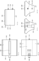
- An Automated Vertical Plant Cultivation System (200) automates indoor plant cultivation by simplifying a process otherwise requiring constant attention.
- the innovative design concept resolves the challenge of introducing plant material into an indoor space in an attractive manner occupying minimum space.
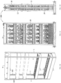
- Fig. 1A shows the assembly's design concept and structural frame.
- the concept's key element is its magazine.
- Fig. 1A -1D depicts the system's fluid circulation system for seed/plant capsule (4) containing nutrient composite (16) supported by electronic devices.
- An inlet shut-off valve (31) passes fluid (5) to a holding/overflow tank (7) through an optional filter cup (32).
- An electric pump (6) lifts the fluid (5) to a gravity tank (9) elevated above magazines (3).
- the fluid (5) may be oxygenated.
- the fluid (5) temperature may be regulated.
- a fluid sensor (45) in the gravity tank (9) monitors the tank's fluid level.
- At least one pipe (12) connects the gravity tank (9) to the plant magazine (3).
- At least one overflow pipe (39) connects the gravity tank (9) to an overflow outlet (33) in magazine/s, an optional filter cup (32) and the overflow/holding tank (7).
- fluid levels at the gravity tanks (5) exceed a set level, fluid flows through the gravity tank overflow bypass (23) directly into an optional detachable filter cup (32) and from there to the holding/overflow tank (7).
- the filter cup (32) collects particles in the fluid (5) and is cleaned periodically.
- Fluid (5) flows to each magazine (3) by gravity.
- a valve (44) controls the volume of fluid (5) permitted to enter the magazine (3).
- the magazine valve (44) operation can be controlled by a moisture/fluid sensor (45) as shown in Figs. 1A & 3B or by the assembly controls (41) responding to a signal from the moisture/fluid sensor (45). In both methods fluid level inside the magazine (3) is monitored. When fluid levels fall below a set level, the sensor (45) directly or indirectly via the assembly controls (41) opens the valve to allow fluid to reach a pre-set level.
- the tank's fluid sensor (35) directly or indirectly via the assembly controller opens the inlet shut-off valve (31) to allow fluid (5) to enter the holding/overflow tank (7) while activating the pump (6) forcing water into the gravity tank (9).
- the fluid circulation system doesn't employ a gravity tank (9) delivering fluid directly to magazine (3). Also, in a different embodiment where direct connectivity to exterior fluid outlet is not available, fluid can be poured directly or indirectly to the holding tank through an inlet.
- Figs. 1A -1D depicts the system's assembly fluid circulation system for both seed/plant capsule employing nutrient composite ( Figs. 6A -6E); a hydroponic capsule having the nutrient mixed in the fluid (Figs. 6F-6J), and a aeroponic capsule having the nutrient mixed in the fluid (Figs. 6K-6O).
- Figs. 6F-6J depict the hydroponic seed/plant capsule in elevations and section form.
- the hydroponic fluid solution is poured through an inlet opening (110) above the holding/ overflow tank (7) or through an inlet opening at the filter cup inlet (112).
- the system is typically connected directly to the fluid access point. Where such point is not available, fluid is poured into the system assembly overflow/holding tank.
- the system's fluid (5) circulation, lighting (46), sound (49), and communication (43) devices are electrically powered and governed in part or in whole by the assembly's control (41). Most or all devices' voltage is stepped down (40).
- the assembly control responsibilities include but are not limited to:
- the assembly's controls (41) consist of a processor with memory that governs in part or in whole a device network consisting of communication module (43), communicating with local or local and remote devices, power distribution bus (59), a thermal probe/heater (116) lighting devices (46), a pump (6), an oxygenator (47), valves (11), a photo sensor (58), a moisture/fluid level sensor (45), an optional back-up power module (48) and/or an audio module (49) and a local or remote I/O communication module (43).
- Input/output to and from the system's assembly control is via a local interface directly mounted to the control panel, on an easy to reach panel at the assembly walls (42) or by remote device.
- a wireless remote device may also be used or be substituted for the control interface.
- the fluid circulation system may employ two types of sensors - a basic type sensing moisture upon contact or a sensor programmed with a fluid level range variability.
- the system includes valves that may be bi-directional, allowing fluid to enter at one inlet and draining fluid in a neighboring outlet.
- the fluid/moisture sensor (45) of the system assembly must be perfectly plumb for proper operation and not subjected to vibrations and/or fluid agitation.
- the system assembly controls (41) Upon activation, the system assembly controls (41) query the operational status of its network devices. Once all devices are confirmed to be online and ready to be used, the fluid's circulation process begins with the fluid sensor/s (45). The sensor/s send input to the controls about fluid levels in some or all the fluid containing vessels. The controls (41) then activate the fluid circulation system.
- the overflow/holding tank fluid level reaches a point triggering the pump (6) to lift the fluid (5) to the gravity tank (9).
- a sensor in the gravity tank is in communication with the pump (9) allowing fluid volume to rise to a pre-set level.
- the magazines' valves (44) open to let fluid in. Fluid flow into the magazine stops by input from the moisture/fluid sensor (45) once the fluid level reaches a pre-set point.
- the flow of fluid to the magazine/s may be preceded by an oxygenator (47) at the gravity tank (9) enriching the oxygen content in the fluid (5) and/or a thermal probe/heater (116) regulating the fluid (5) temperature.
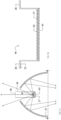
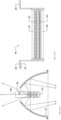
- Figs. 3A shows partial elevations of the magazine's power connectivity and fluid external circulation system.
- Fig. 3B shows the fluid inlet (8), inside the magazine's inlet reservoir (37), an inlet valve (44) which permits fluid to enter the magazine and the moisture/fluid sensor (45) abutting the valve (44). Both operate in unison to control fluid level in the magazine. Any access fluid (5) drains down to the filter cup (32) or directly into the overflow tank (7) through the magazine's overflow outlet (33).
- bi-directional valves may be used to let fluid in the magazine and then drain it out to the overflow/holding tank in a cyclical manner.
- Fig. 3A shows the opposite end of the magazine's fluid inlet. This end receives power or power/data from the power/data bus conveying it to devices inside/on the magazine and downstream devices. It has a small compartment to install a power supply/modulator if needed and conceal wiring slack. Inside/on the magazine the common devices may include valve/s, sensor/s, light module/s, temperature probe and photo sensor. The power or power/data is conveyed in the magazine through fluid channel covers.
- Figs. 4A -4L shows the covers with their respective power or power/data receptacles.
- Figs. 4E-4H show a plug & play receptacle in the cover top and bottom faces.
- Figs. 4I-4L show the cover with its power/data pronged connectors to moisture/fluid sensor (45) and valve/s (44) in the fluid inlet reservoir (37).
- the lighting devices (46) operate by the controller's (41) programmed schedule or can operate manually. Power enters the reflector's aperture (56) from the fluid channel cover (38).
- the receptacles (53) for the lighting devices (46) are located on the fluid channel cover (38).
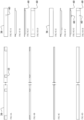
- Figs. 7A -7D shows the lighting device (46) consisting of a "U" shaped element having lateral outwardly extensions (26) on the upright legs' top end. The extensions serve as hanging points for the lighting device (46) and power or power/data connectivity point at one side.
- a light source (65) strip typically LED cultured onto a substrate mounted onto a heatsink (27) having fins (63) to dissipate the heat generated by the light source (65).
- the non-powered hanger can conduct the heat into the fluid channel (22) when needed.
- the light source (65) spectral distribution via the assembly controls (41) can be modulated. Such modulation can provide pleasant illumination during periods where the space is occupied, or switching to grow light spectral distribution when the space is vacant of occupants or per schedule.
- the light output can also be modulated with programmed pre-set output modes.
- the lighting device (46) is detachable, shielded from direct contact by a reflector assembly and safe from electrical shock being powered by low voltage.
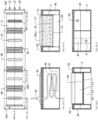
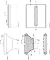
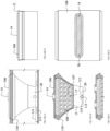
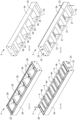
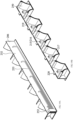
- the magazine (3) is an embodiment providing structural support to plant material, acting as a fluid containing vessel, and providing illumination to plants, as depicted in Figs. 2A -5M and 8A-11D.
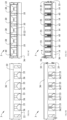
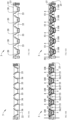
- Figs. 5A- 5B shows the magazine in section, where section Fig. 5A shows the structure only and Fig. 5B shows the section structure with seed/plant capsules (4) and lighting devices (46).
- the magazine is commonly made of non-porous material sufficiently rigid to support its weight, seed/plant capsules (4), fluid (5), and lighting devices (46) over relatively long spans. Alternatively, the magazine may be made of non-porous materials with lining to contain fluid.
- the most common form of magazine (3) shown in Figs. 2A -2C is rectangular.
- a rectangular magazine has at least one double wall (36) along its long axis to form the fluid channel (22) between walls.
- the fluid channel at the inner magazine wall (36) drain into multiple plant/seed capsule reservoirs (20).
- These reservoirs shown in Figs. 5C and 5I and 8A-11D are alternately located between lighting reflector apertures (55) shown in Figs. 7A -7D.
- a micro valve (44) controls fluid (5) flow into the magazine (3).
- fluid (5) enters the magazine (3) it flows into an inlet reservoir (37) and from there to the magazine fluid channel (22).
- the fluid (5) then flows to the magazine plant/seed capsule reservoir (20) maintaining an equal level at all reservoirs when magazines are horizontally plumb.
- a moisture/fluid sensor (45) directly or indirectly via the assembly controller (41) maintains a pre-set fluid level by controlling the micro valve (44) operation.
- the moisture/fluid sensor (45) can be integrated with the micro valve (44) as shown in Fig. 3B or remote at the opposite end of the magazine fluid inlet (25).
- the plant/seed capsules (4) inserted into the capsule reservoir (20) are immersed in the fluid (5).
- the fluid (5) level rises just above the seed's (17) vertical elevation placement.
- Aeroponic magazine embodiment shown in FIGs. 6K and 6L includes a piping network (113) with mounts (115) through the fluid channel/s leading to the plant/seed reservoir. There fluid atomizers (114) spray their mist onto the plant root.
- the aeroponic valve may serve as an inlet and drain valve in conjunction with the fluid pump excluding the use of the gravity tank.
- the magazine's (3) fluid circulation system employs detachable fluid channel covers (38) to protect the circulation system from contamination, harboring insects and evaporation.
- a cover (106) provides equal protection.
- a light aperture opening cover (117) is used where no light device is used or there is no need for up-lighting.
- Figs. 5A-5M and Fig. 7A -7D and Figs. 8A -11D show how the lighting devices are integrated into the magazine's architecture.
- the magazine's lighting devices (46) are located between the plant/seed capsule reservoirs (20). These devices (46) are substantially concealed from direct viewing by reflector apertures (55) which also acts as the exterior wall of the plant/seed capsule reservoir (21). The reflector's short ends are abutting the magazine's fluid channel (22) walls. Power flows to the lighting devices through conductors embedded in the fluid channel cover (38). The lighting device rests on the channel cover at both sides of the magazine and plug-in prongs at one side engage a corresponding receptacle on the top surface of the fluid channel cover.
- Fig. 7A -7D and 8A-11D shows the reflector aperture partly open at is apex. Hung from both ends, the lighting device light source (65) is optimally located inside the reflector (55) to cast illumination upwardly and downwardly.
- the opening at the reflector's (55) apex permits direct light to illuminate the bottom of the plant (29) canopy.
- the reflector (55) surface can be made partially or fully of highly reflective material.
- the reflector aperture (55) confines the distribution light beam pattern to substantially fall on plant (29) material and not stray beyond. This capability is important when light spectral distribution which is harmful to human exposure is used.
- the light source (65) spectral wavelength can be limited to "grow light” spectral distribution only, or can also include other spectral distributions. In such settings, the light emittance can be set on a scheduler governed by the system controller.
- the reflector aperture opening (56) enables air to flow from the bottom to the top of the magazine (3), cooling the lighting device and eliminating heat stratification.
- the lighting device's (46) un-powered hanging leg can cool the device by conducting heat into the fluid channel (22).
- bi-directional illumination is provided by having two light sources aimed at substantially opposite directions.
- Figs. 7A -7D shows two light sources mounted on the lighting device inside the reflector, where one is aimed upwardly and the other downwardly.
- the same lighting device may employ at least one light source.
- the system may also employ a lighting device in the vicinity of the gravity tank. This device's use may include illuminating the space where the light band spectrum emulates sunlight, and is used in dark environments where occupants may develop SAD (Seasonal Affective Disorder).
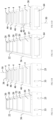
- the plant/seed capsule (4) is an enclosure made of non-porous material with openings on top and on the bottom. The openings are sealed (110) to air and moisture and are removed prior to the capsule's deployment.
- the capsule contains one or several seeds of same or different plant (29) species.
- the seed (17) is embedded in a nutrient composite (16) and is suspended in scaffolding material (108) to enable root structure to establish a firm hold for the plant (29) once the seed (17) germinates.
- scaffolding material (108) to enable root structure to establish a firm hold for the plant (29) once the seed (17) germinates.
- Fig. 5K, 6G and 6L show the seeds inside the plant/seed capsule placed in a sack (107) surrounded by scaffolding material absent nutrients.
- the production of the nutrient composite (16) employing non-hydroponic or non-aeroponic methods is tightly controlled to provide the correct balance of nutrients for the plant (29) species and protect from any life form including any in a dormant state.
- the production process reduces or removes moisture content in the composite and in some applications also removes air.
- a root membrane (15) permits fluid (5) to percolate into the capsule and upon seed (17) germination, allows the root system to penetrate the membrane (15) while containing the nutrient composite (16) inside the capsule.
- the plant/seed capsule (4) cap has a through sprout port through which the plant material sprouts. Some plant/seed capsules may come with several sprout openings.
- a seal (110) surrounding the capsule's top wall prevents fluid/moisture infiltration.
- the system is a load bearing assembly containing mechanical, electrical and plant material.
- Fig. 1A shows the key structural members.
- the assembly form is typically a square or rectangular.
- the structural members supporting the assembly include at least two vertical and two horizontal members at the assembly's periphery.
- the horizontal member at the bottom of the frame typically supports the pump (6), the holding/overflow tank (7), the control panel (41) and other electrical/electronic equipment.
- the horizontal member on top supports the gravity tank (9).
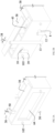
- the plant magazines (3) span across the vertical members latching onto them by adjustable fasteners (105). The adjustable fasteners free the magazine to travel vertically and be secured at the desired location.
- the magazines (3) are structurally rigid supplementing the assembly's overall structural strength.
- the vertical members may be opaque, or made of a see-through frame.
- the fluid's vertical circulatory pipe system travels along one end of the support member/s while the electrical/data vertical circulatory system travels along the other end.
- a wired or wireless interface panel can be placed on the vertical members' wall.
- the assembly design rating is for full loading and may include a rating capacity for suspended assemblies.
- the plant seed and seedling capsules (4) are nestled inside the magazine's capsule vessels (20).
- the capsule (4) may be provided having one or several of the following features:
- a plant capsule (4) may contain at least one valve that, through the system's (200) processor, controls the amount of fluid entering into the plant capsule vessel (20) and the duration of how long the fluid remains there.
- the processor may inform the user about the plant growth cycle, alert when sensing anomalies, and suggest how the plant material can be used when it becomes edible.
- the processor may also be communicatively coupled to a device in a remote location, engaging the user with suggestions, promotions and chat rooms of other system (200) users. Further, the system may include a dehumidifier in order to ensure that the optimal humidity for particular plants as identified from the keyed capsule to optimize the growth cycle of that particular plant.
- the plant capsule (4) size and shape may vary, as well as its plant aperture size and number of its cap openings.
- the capsule (4) can be fabricated for a one-time use, or can employ a removable cap for multiple uses.
- a multiple use capsule (4) may enable the replacement of spent plant material with new seed sacks or seedling bundles upon completion of a plant growth cycle.
- Operable replenished capsules (4) may be provided on a subscription basis where the processor can reset the capsule for a new growth cycle.
- the processor may de-activate the capsule's (4) optimization of the plant growth cycle. Under authorized use, plant material inside the capsule (4) receives the optimal amount of fluid, nutrition, and light at the correct spectral wavelength and duration.
- sensing devices may be used or a part of the system (200) and in communication with the processor wherein the processor can monitor, alert, and act on invading pests and identify unhealthy changes in the plant foliage in response to information and data provided by the sensing devices.
- Additional embodiments may include a miniaturized flying device or drone that may under control or autonomously fly over the system (200) and the plant material, sense blooming flowers and then pollinate the blooming flowers. Additionally, the miniaturized flying device or drone may also sense anomalies in plant foliage and communicate its finding to the processor as it flies over the system (200) and the plant material.
- Figs. 12A-E depict views of the seed or plant capsule which can be used with multi-cultivation methods.
- Fig. 12A shows the seed or plant capsule (250) top view with cap plant's aperture (201) opening at its center and the capsule's (250) power/data interface (228) extending outwardly from face of the capsule by the fluid supply channel (206) side (not shown).
- Fig 12B shows the capsule (250) bottom view.
- a capsule valve recess (233), a seed or plant capsule stem pipe bore (235) and the power or power and data chase (225) form an enclosure to house the low voltage fluid supply valve (214), enable a valve pipe stem (215) (not shown) to enter the capsule (250) (not shown) and electrically connect to the capsule's power or power and data interface (228) shown extending from face of capsule outwardly.
- a drain port through bolt (211) drains the capsule's (250) fluid when it employs an aeroponic cultivation method.
- Fluid entering the capsule wets the plant/s root structure and then is evacuated and recycled back to the cultivator's holding tank and then the fluid periodically repeats its circulation cycle.
- the through drain bolt (211) is capped by the drain port cap (212) when another cultivation method is employed.
- Fig. 12C shows the capsule's (250) exterior wall by supply channel (219) side.
- a recess in the capsule's wall forms an enclosure to house the low voltage fluid supply valve (214) with its power or power and data chase (225).
- Above the chase an electronic memory device (223) can be embedded in the capsule's housing or inserted to the power and data interface (228).
- the electronic memory device (223) can be integral to the capsule's (250) body, or securely attached to the body in a secondary fabrication process.
- Fig. 12D shows the capsule's (250) exterior wall by the fluid evacuation channel (218) side.
- a drain port through bolt (211) drains the capsules' (250) fluid when employing an aeroponic cultivation method.
- the through bolt (211) is capped when employing other cultivation methods.
- an overflow port through bolt evacuates fluid to the fluid evacuation channel (205) when fluid levels exceed a threshold.
- the profile of the cap's plant aperture (201) may vary in size and location at the cap's top face based on the selected plant material.
- Fig. 12E shows the capsule (250) side elevation.
- the capsule's power and data interface (228) extends outwardly beyond the face of the capsule's wall at the supply channel (219) side.
- the drain port through bolt (211) is shown at the bottom with a cap (212) and above an overflow port through bolt (210).
- Figs. 13A-B show partial perspectives of the fluid supply channel (206) at the low voltage valve (214) inlet and the seed or plant capsule fluid supply side wall (232).
- Fig. 13A shows the fluid supply channel (206), the channel cover (222) power/data receptacle (224), conductors (230), the low voltage fluid valve (214) with its power or power and data chase (225) and the valve's pipe stem (215).
- the valve (214) is secured to the supply channel inner wall by the valve through bolt (220) with a gasket (221) and a nut (226) (not shown).
- Power entering from the power or power and data chase (225) activates the low voltage valve (214) when sensing device/s (not shown) sense that fluid level inside the seed or plant capsule (250) is low. The valve's activation can be prompted by the processor or by the local sensing device.
- Fluid then travels through the valve (214) and the pipe stem (215) into the seed or plant capsule (250) (not shown). Delivering fluid inside the capsule above the seed or plant roots prevents the roots from clogging the fluid inlet/s.
- the pipe stem (215) shown in this figure and section Fig 15a illustrate the solution. In a different embodiment (not shown) fluid can enter the capsule directly from the fluid supply channel accomplishing the same purpose.
- Fig. 13B shows the seed or plant capsule (250) side wall abutting the fluid supply channel (206) inner wall.
- a recess at the bottom of the wall extending upwardly houses the low voltage fluid supply valve (214) and the power or power and data chase (225).
- the "L"-shaped capsule's power and data interface (228) extends outwardly.
- the interface establishes power and data connectivity to support the capsule's operation upon engaging its "L" shaped interface leg in the channel cover (222) receptacle (224).
- the interface can have an electronic memory device (223) storing pertinent information about the capsule's (250) content including OEM authentication data.
- the capsule's device network supporting its plant cultivation is activated only after the cultivator processor (not shown) authenticates it.
- Figs. 14A-B show a partial top view of the fluid supply channel and a partial bottom view of the fluid supply side of the seed or plant capsule.
- Fig. 14A shows the fluid supply cover (222) with a receptacle (224).
- the receptacle (224) engages the "L"-shaped capsule's power and data interface (228) of the seed or plant capsule (250).
- the channel cover (222) can have a plurality of receptacles (228) engaging different types of devices, including power input devices such as valves, lighting devices and sensing devices such as thermal, fluid pH levels, humidity and light sensors.
- the low voltage valve (214) receives power or power flowing from the power or power and data chase (225).
- the chase can be an integral part of the low voltage valve (214) assembly.
- the low voltage valve (214) delivers fluid into the seed or plant capsule (250) through a pipe's valve stem (215).
- the stem enters the seed or plant capsule bore (235) located at the capsule's valve recess (233), both shown in Fig 14b .
- the pipe's valve stem can include a seal/gasket (216) preventing fluid backflow into the seed or plant capsule's reservoir (229) (not shown).
- Fig. 14B shows a partial view of the seed or plant capsule bottom (229) at the fluid supply (206) side.
- the low voltage valve (215) pipe stem (215) enters the seed or plant capsule (250) through the seed or plant capsule bore (235) located at the capsule's valve recess (233).
- Extending out from the capsule's wall at supply channel (219) side is the "L"-shaped capsule's power and data interface (228).
- the interface provides power to the low voltage valve (214) and can communicate with the valve.
- the memory storage device (223) can be embedded inside the interface (228) or affixed to it (not shown).
- the storage device (223) authenticates the capsule (250), obtains information and optimizes the capsule's operation.
- Figs. 15A-C show partial longitudinal sections of the seed or plant capsule (250) inside the seed or plant capsule's reservoir (236) at the fluid supply channel (206) side.
- a low voltage valve (214) controlled by the cultivator processor (not shown) flows fluid from the supply channel (206) to the seed or plant capsule reservoir (236) into the seed or plant capsule (250).
- the fluid reaches the capsule (250) passing through the valve's through bolt (220) to the valve's piped stem (215) penetrating the seed or plant capsule (250) from below through the capsule's stem pipe bore (235).
- the fluid level inside the capsule is equalized by barometric pressure with the fluid inside the supply channel (206).
- a sensing device can provide a signal to the processor when to operate the valve (214).
- a simple mechanical device such as a float valve (not shown) can also control the in-flow fluid supply to the capsule (250).
- the capsule's irrigation method dictates the amount of fluid and the duration of the irrigation into the seed or plant capsule (250).
- the valve's piped stem (215) can have a pipe stem seal/gasket (216) or such seal can be provided as a self-sealing membrane on top of the capsule's stem pipe bore (235). Either way, the seal or gaskets prevent fluid backflow into the seed or plant capsule reservoir (236).
- the valve (214) is secured to the inner wall of the fluid supply channel (207) by a valve through bolt (220) with a valve through nut (226) and a gasket (221).
- the gasket (221) prevents fluid travel into the seed or plant reservoir (236).
- the "L"-shaped power or power and data chase (225) is shown wedged between the exterior face of the seed or plant capsule (219) and the fluid supply channel interior wall (207).
- the chase (225) in this embodiment is integral to the low voltage valve (214). In other embodiments it can in part or in whole attach to the reservoir wall (214). In other embodiments the chase can be configured as a part of the capsule's assembly.
- the chase (225) mates with the capsule's power and data interface (228) which in turn mates with a receptacle (224) in the fluid supply cover (222).
- a root structure scaffolding (203) is shown inside the seed or plant capsule (250).
- the scaffolding provides the attachment structure for the plant's roots.
- the scaffolding could have a volumetric opening to insert seed pouch and/or other time release additives.
- Figs. 15B and 15C show a partial longitudinal section of the seed or plant capsule (250) at the fluid evacuation channel (205) side.
- An overflow port through bolt (210) above the mid-section of the seed or plant capsule (250) wall abutting the evacuation channel (205) removes access fluid from the capsule when the low voltage valve (214) fails. In such an event, overflowed fluid is evacuated through the channel (205) returning back to the holding tank (not shown) to be re-circulated. When unanticipated fluid circulation occurs, the processor can alert users about the event and may also identify the specific nature of the failure. Below the overflow port through bolt (210), the drain port through bolt (211) evacuates fluid from the seed or plant capsule (250) when needed.
- This port is typically used when the capsule is operated employing an aeroponic irrigation method.
- the plants' root (227) are kept moist by circulating fluid and evacuating the fluid from the capsule periodically.
- the drain port through bolt (211) can simply be capped off by employing a drain port cap (212).
- fluid level inside the capsule is maintained sufficiently high to prompt the seeds to develop their root structure.
- the capsule (250) design employing a dual port system with the valve pipe stem (215) is an innovation the enables the use of a single capsule design with most common irrigation methods.
- Figs. 16A and 16B show a partial section of the fluid supply channel with a view from the seed or plant reservoir side and the side view of the seed or plant capsule at the fluid entry to the capsule side.
- Fig. 16A shows the fluid entry stand (245) against the seed or plant capsule fluid supply inner wall (232) with its fluid inlet pipe stem (215) and pipe seal/gasket (216). Fluid entering from the supply channel (206) rises through the fluid inlet pipe stems (215) entering the seed or plant capsule (250). A seal/gasket (216) prevents fluid from returning to the supply channel (206) and/or reservoir (229).
- the magazine's pipe stems can deliver fluid to all capsules simultaneously or to individual capsules where and when needed.
- Fig. 16B shows the supply side face of a seed or plant capsule (250).
- a fluid inlet stand recess (251) houses the fluid inlet stand (245).
- the pipe stem (215) penetrates the capsule's (250) interior.
- a seal/gasket (216) located on the pipe, the capsule or both prevents fluid back flow.
- the capsule may employ a memory device (231) and a capsule power and data interface (228) (not shown) to control the illumination and fluid circulation of the capsule.
- Figs. 17A, 17B and 17C show partial longitudinal sections across a seed or plant capsule nestled inside a magazine.
- Fig. 17A shows a pipe stem (215) originating at the fluid supply channel (206) and terminating inside the seed or plant capsule (250).
- a membrane seal/gasket (216) is located on the pipe stem stand (215). Fluid from the supply channel (206) enters the capsule's (250) interior above the seeds or plants' root structure. In so doing the roots are prevented from clogging the fluid supply ports.
- a fluid sensor probe (257) can be embedded or attached to the wall. The probe in real time communicates data about the moisture level inside the capsule (250) to the processor to insure optimal plant growth fluid level.
- the seed or plant capsule floor (217) is sloped from the fluid channel supply side toward the fluid evacuation channel (205) side.
- the capsule (250) retains the plants in place by employing a root structure scaffolding (203). This 3D structure enables the roots to wrap around the structure membrane and support the growth of sizable plants.
- Figs. 17B and 17C show partial longitudinal sections of the seed or plant capsule (250) at the fluid evacuation channel (205) side.
- An overflow port through bolt (210) above the mid-section of the seed or plant capsule (250) wall abutting the evacuation channel (205) removes access fluid from the capsule when the low voltage valve (214) (not shown) fails. In such an event, overflowed fluid is evacuated through the channel (205) returning back to the holding tank (not shown) to be re-circulated. When unanticipated fluid circulation is sensed, the processor can alert users about the event and may also identify the specific nature of the failure. Below the overflow port through bolt (210), the drain port through bolt (211) evacuates fluid from the seed or plant capsule (250) when needed.
- This port is typically used when the capsule is operated employing an aeroponic irrigation method.
- the plants' roots (227) are kept moist by circulating fluid and evacuating the fluid from the capsule periodically.
- the drain port through bolt (211) can simply be capped off by employing a drain port cap (212).
- fluid level inside the capsule is maintained sufficiently high to prompt the seeds to develop their root structure.
- the seed or plant capsule floor (217) shown in this embodiment is sloped to flow fluid toward the drain port through bolt (211).
- the capsule (250) design employing a dual port system with the valve pipe stem (215) is an innovation which enables the use of a single capsule design with common irrigation methods.
- Figs. 18A, 18B and 18C show partial longitudinal sections across a seed or plant capsule nested inside a magazine.
- Fig 18a shows a pipe stem (215) originating at the fluid supply channel (206) and terminating inside the seed or plant capsule (250).
- a membrane seal/gasket (216) is located on the pipe stem stand (215). Fluid from the supply channel (206) enters the capsules' (250) interior above the seeds or plants' root structure. In so doing the roots are prevented from clogging the fluid supply port/s.
- a fluid sensor probe (257) can be embedded or attached to the wall.
- fluid entering the magazine is channeled into a multi-port valve (252) (not shown). From there the fluid travels through fluid supply pipes (255) into the capsules (250).
- the valve (252) may have an integral fluid pipe with power and communication receptacle/s (224) connecting to receptacles on the fluid channel cover (222).
- a fluid sensor probe (257) can be embedded or attached to the wall. The probe in real time communicates data about the moisture level inside the capsule (250) to the processor to insure optimal plant growth.
- the seed or plant capsule floor (217) is sloped from the fluid channel supply side toward the fluid evacuation channel (205) side. Regardless of the cultivation methods fluid is prevented from becoming stagnant inside the capsule.
- the capsule (250) retains the plants in place by employing a root structure scaffolding (203). This 3D structure enables the roots to wrap around the structure membrane and support the growth of sizable plants.
- Figs. 18B and 18C show partial longitudinal sections of the seed or plant capsule (250) at the fluid evacuation channel (205) side.
- An overflow port through bolt (210) above the mid-section of the seed or plant capsule (250) wall abutting the evacuation channel (205) removes access fluid from the capsule when the low voltage valve (214) fails. In such an event, overflowed fluid is evacuated through the channel (205) returning back to the holding tank (not shown) to be re-circulated. When unanticipated fluid circulation occurs, the processor can alert users about the event and may also identify the specific nature of the failure. Below the overflow port through bolt (210), the drain port through bolt (211) evacuates fluid from the seed or plant capsule (250) when needed.
- This port is typically used when the capsule is operated employing an aeroponic irrigation method.
- the plants' roots (227) are kept moist by circulating fluid and evacuating the fluid from the capsule periodically.
- the drain port through bolt (211) can simply be capped off by employing a drain port cap (212).
- fluid level inside the capsule is maintained sufficiently high to prompt the seeds to develop their root structure.
- the seed or plant capsule floor (217) shown in this embodiment is sloped to flow fluid toward the drain poet through bolt (211).
- the capsule (250) design employing a dual port system with the valve pipe stem (215) is an innovation which enables the use of a single capsule design with common irrigation methods.
- Figs. 19A and 19B show longitudinal sections through the fluid supply channel and the magazine.
- Fig. 19A shows the multi-port fluid valve or multi-port fluid valve with pump (252) at the magazine (248) fluid entry side. Fluid flowing into the magazine is channeled into the multi-port valve (252) and from there through the fluid supply pipe (255) to enter the seed or plant capsules individually when needed.
- the multi-port valve (252) can be located inside the fluid channel (206) and powered and communicated to and from the receptacle (224) in the fluid channel cover (222).
- the multi-port valve (252) may also have an integrated pump. The pump may be included when gravity flow is not used to flow fluid into the magazine (248).
- Fig. 19B shows the seed or plant capsule's reservoir (236) at the fluid supply channel wall at the capsule side (232).
- the fluid inlet stand (245) with the pipe stem (215) and pipe stem seal/gasket (216) enable fluid supply and fluid retention inside the seed or plant capsule (250).
- a fluid sensor probe (257) not shown) can be embedded or attached to the wall of the fluid inlet stand (245) inside the capsule's reservoir (236). The fluid sensor probe can receive power through the capsule's power and data interface (228) and have bi-directional communication when the capsule (250) is seated inside the capsule's reservoir (236).
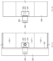
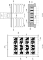
- Figs. 20A, 20B and 20C show a cultivation split system assembly whereas in the embodiment shown the magazines are recessed in a wall niche and other power and fluid retaining and pumping equipment are concealed from viewing in remote location/s.
- Fig. 20A shows a block diagram of two magazine vertical arrays, each having four magazines powered and fluid supplied from a remote location through a wall (249).
- the processor (243) and the fluid tank/s (249) provide for a plurality of cultivators from a remote location.
- other system components can interchange with the aforementioned components and be placed remotely. These components may include power back-up supply, transceiver, sensing devices, oxygenator, filtering devices and heating/cooling equipment.
- Fig. 20B shows a wall (249) niche with four magazines (248) occupying the recessed niche space.
- the magazines (248) are showing plant material (244), floor slab (239) and tile ceiling (238). Also shown is a horizontal section 16c with a view looking down onto a magazine (248) inside the niche.
- Fig. 20C shows a horizontal section looking down onto a magazine (248) inside a wall (249) niche.
- the magazine (248) in this embodiment is supported by four wall mounting brackets (240) with fluid vertical circulatory piping (241) running on one side of the magazine and power/data conductors (242) running vertically on the other side.
- the magazine (248) shows five seed or plant capsules (250) with each having a single plant aperture (201) and four magazine heat dissipating vents (246). In this embodiment both systems are concealed from direct viewing.
- the magazine can be mounted against the wall supported by wall brackets (not shown).
Landscapes
- Life Sciences & Earth Sciences (AREA)
- Environmental Sciences (AREA)
- Hydroponics (AREA)
- Greenhouses (AREA)
- Cultivation Receptacles Or Flower-Pots, Or Pots For Seedlings (AREA)
Applications Claiming Priority (5)
| Application Number | Priority Date | Filing Date | Title |
|---|---|---|---|
| US15/589,845 US10524433B2 (en) | 2017-05-08 | 2017-05-08 | Automated vertical plant cultivation system |
| US201762592246P | 2017-11-29 | 2017-11-29 | |
| US15/885,157 US11304390B2 (en) | 2017-05-08 | 2018-01-31 | Automated vertical plant cultivation system |
| EP18797961.2A EP3621426B1 (fr) | 2017-05-08 | 2018-05-07 | Système automatisé vertical de culture de plantes |
| PCT/US2018/031429 WO2018208686A1 (fr) | 2017-05-08 | 2018-05-07 | Système automatisé vertical de culture de plantes |
Related Parent Applications (2)
| Application Number | Title | Priority Date | Filing Date |
|---|---|---|---|
| EP18797961.2A Division EP3621426B1 (fr) | 2017-05-08 | 2018-05-07 | Système automatisé vertical de culture de plantes |
| EP18797961.2A Division-Into EP3621426B1 (fr) | 2017-05-08 | 2018-05-07 | Système automatisé vertical de culture de plantes |
Publications (2)
| Publication Number | Publication Date |
|---|---|
| EP4233526A2 true EP4233526A2 (fr) | 2023-08-30 |
| EP4233526A3 EP4233526A3 (fr) | 2023-10-18 |
Family
ID=64013455
Family Applications (3)
| Application Number | Title | Priority Date | Filing Date |
|---|---|---|---|
| EP23163789.3A Pending EP4233526A3 (fr) | 2017-05-08 | 2018-05-07 | Système automatisé vertical de culture de plantes |
| EP19214341.0A Active EP3666064B1 (fr) | 2017-05-08 | 2018-05-07 | Système automatisé de culture de plantes vertical |
| EP18797961.2A Active EP3621426B1 (fr) | 2017-05-08 | 2018-05-07 | Système automatisé vertical de culture de plantes |
Family Applications After (2)
| Application Number | Title | Priority Date | Filing Date |
|---|---|---|---|
| EP19214341.0A Active EP3666064B1 (fr) | 2017-05-08 | 2018-05-07 | Système automatisé de culture de plantes vertical |
| EP18797961.2A Active EP3621426B1 (fr) | 2017-05-08 | 2018-05-07 | Système automatisé vertical de culture de plantes |
Country Status (2)
| Country | Link |
|---|---|
| EP (3) | EP4233526A3 (fr) |
| CN (1) | CN111343859A (fr) |
Families Citing this family (3)
| Publication number | Priority date | Publication date | Assignee | Title |
|---|---|---|---|---|
| DE102020134776B4 (de) | 2020-12-22 | 2023-05-25 | urbanhive GmbH | Modulares System für Hydrokulturen für den Einsatz im Innenraum |
| US20230124203A1 (en) * | 2021-10-14 | 2023-04-20 | Haier Us Appliance Solutions, Inc. | Plant training pods for an indoor gardening appliance |
| CN116098009B (zh) * | 2023-02-08 | 2023-06-30 | 沂源县大张庄镇文化旅游发展中心 | 具备苗木防护和温度调节功能的林业树苗培育装置及方法 |
Family Cites Families (31)
| Publication number | Priority date | Publication date | Assignee | Title |
|---|---|---|---|---|
| US4845602A (en) * | 1988-06-23 | 1989-07-04 | Lehocki Stephen C | Combination plant holder and light globe |
| GB0004199D0 (en) * | 2000-02-22 | 2000-04-12 | Winsbury Barry | System |
| EP1859673A4 (fr) * | 2005-03-14 | 2009-01-21 | Tokuju Kogyo Co Ltd | Dispositif d eclairage et dispositif de culture de plantes equipe d un dispositif d eclairage |
| KR101345365B1 (ko) * | 2006-10-19 | 2013-12-30 | 코닌클리케 필립스 엔.브이. | 식물 재배 장치 |
| JP2008136426A (ja) * | 2006-12-04 | 2008-06-19 | Japan Plants Co Ltd | 植物配送システム |
| US20090151248A1 (en) * | 2007-10-30 | 2009-06-18 | Aerogrow International, Inc. | Devices and methods for growing plants |
| EP2242706B1 (fr) * | 2008-02-06 | 2011-09-28 | Koninklijke Philips Electronics N.V. | Conteneur destiné à contenir un organisme vivant, station d arrimage et système de transport |
| DE102009010579A1 (de) * | 2009-02-25 | 2010-08-26 | ETH Zürich | System und Verfahren zur Fernüberwachung von Objekten |
| CN201663838U (zh) * | 2010-04-07 | 2010-12-08 | 杭州健尔基生物科技有限公司 | 家用物联抽屉式蔬菜生产柜 |
| KR101227959B1 (ko) * | 2010-08-12 | 2013-01-30 | 정관선 | 엘이디조명 일체형 식물공장용 수경재배장치 |
| US20120054061A1 (en) * | 2010-08-26 | 2012-03-01 | Fok Philip E | Produce production system and process |
| KR101281116B1 (ko) * | 2010-10-25 | 2013-07-02 | (주)창조인프라 | 분리 가능한 엘이디조명 대용 받침대를 구비하는 식물재배장치 |
| US20140173769A1 (en) * | 2011-01-24 | 2014-06-19 | Basf Plant Science Company Gmbh | System for Monitoring Growth Conditions of Plants |
| US8763303B2 (en) * | 2011-04-04 | 2014-07-01 | Curb Allure LLC | Tree guard |
| KR101212130B1 (ko) * | 2012-06-18 | 2012-12-13 | 서울대학교산학협력단 | 새싹채소 재배 카트리지 및 이를 포함하는 새싹채소 자동재배 장치 |
| KR101423127B1 (ko) * | 2012-10-17 | 2014-07-25 | 지엠지코리아 주식회사 | 수경재배장치 |
| US10555466B2 (en) * | 2012-11-26 | 2020-02-11 | Daegan Gonyer | Modular automated growing system |
| CN103026888A (zh) * | 2013-01-07 | 2013-04-10 | 倪龙 | 植物栽培方法、栽培模块及商业用途 |
| US9526215B2 (en) * | 2013-03-05 | 2016-12-27 | Xiant Technologies, Inc. | Photon modulation management system |
| JP2015019634A (ja) * | 2013-07-22 | 2015-02-02 | 興和株式会社 | 水耕栽培用育苗装置及びその育苗装置に使用される栽培ポット |
| KR20150001100U (ko) * | 2013-09-04 | 2015-03-12 | 김정희 | 홍보용 화분대 |
| CN103416292B (zh) * | 2013-09-11 | 2015-07-22 | 王爱武 | 家用全自动蔬菜种植机 |
| GB2516515B8 (en) * | 2013-12-04 | 2016-10-05 | Intelligent Growth Solutions Ltd | Automated arrangement to grow plants under lighting in a vertical tower |
| CN103632295A (zh) * | 2013-12-24 | 2014-03-12 | 宁波保税区攀峒信息科技有限公司 | 一种可指定确定产品的生鲜农产品产销模式 |
| CN103650971A (zh) * | 2013-12-24 | 2014-03-26 | 宁波保税区攀峒信息科技有限公司 | 一种保水保肥且独立于环境的植物栽培模块 |
| US20160360712A1 (en) * | 2015-06-15 | 2016-12-15 | Biological Innovation & Optimization Systems, LLC | Grow lighting and agricultural systems and methods |
| WO2017024353A1 (fr) * | 2015-08-11 | 2017-02-16 | E Agri Pte Ltd | Systèmes, procédés et appareil d'horticulture à haute densité |
| US20170094920A1 (en) * | 2015-10-02 | 2017-04-06 | Craig Ellins | Integrated incubation, cultivation and curing system and controls for optimizing and enhancing plant growth, development and performance of plant-based medical therapies |
| CN206101195U (zh) * | 2016-08-02 | 2017-04-19 | 武汉市农业科学技术研究院农业机械化科学研究所 | 阳台柜式自循环水培种植装置 |
| CN106561442A (zh) * | 2016-11-01 | 2017-04-19 | 于葵 | 蔬菜种植机箱 |
| CN106386457A (zh) * | 2016-11-08 | 2017-02-15 | 江苏省农业科学院 | 一种叶菜植物栽培系统 |
-
2018
- 2018-05-07 EP EP23163789.3A patent/EP4233526A3/fr active Pending
- 2018-05-07 EP EP19214341.0A patent/EP3666064B1/fr active Active
- 2018-05-07 CN CN201880040481.5A patent/CN111343859A/zh active Pending
- 2018-05-07 EP EP18797961.2A patent/EP3621426B1/fr active Active
Also Published As
| Publication number | Publication date |
|---|---|
| CN111343859A (zh) | 2020-06-26 |
| EP3666064B1 (fr) | 2021-09-29 |
| EP3621426A1 (fr) | 2020-03-18 |
| EP4233526A3 (fr) | 2023-10-18 |
| EP3666064A1 (fr) | 2020-06-17 |
| EP3621426A4 (fr) | 2021-03-03 |
| EP3621426B1 (fr) | 2023-06-07 |
| EP3621426C0 (fr) | 2023-06-07 |
Similar Documents
| Publication | Publication Date | Title |
|---|---|---|
| US11129339B2 (en) | Automated vertical plant cultivation system | |
| US11617309B2 (en) | Automated vertical plant cultivation system | |
| US11730097B2 (en) | Automated vertical plant cultivation system | |
| US11304390B2 (en) | Automated vertical plant cultivation system | |
| US9241453B1 (en) | Aeroponic commercial plant cultivation system utilizing a grow enclosure | |
| EP3621426B1 (fr) | Système automatisé vertical de culture de plantes | |
| US20200323151A1 (en) | Automated vertical plant cultivation system | |
| KR101582389B1 (ko) | 무선 제어 가능한 식물 재배 시스템 | |
| KR20140057482A (ko) | 다단식 실내 경작방법과 장치 | |
| KR20190089481A (ko) | 가정용 식물재배를 위한 스마트 식물재배장치 | |
| KR20140018572A (ko) | 실내용 수경재배장치 | |
| JP6227372B2 (ja) | 植物育成装置 | |
| KR102330448B1 (ko) | 아쿠아포닉스 스마트팜 | |
| KR20120126832A (ko) | 다기능 화분장치 | |
| PL226238B1 (pl) | Sposob i system wertykalnej uprawy roslin w doniczkach, urzadzenie do wertykalnej uprawy roslin w doniczkach oraz specjalna doniczka | |
| KR20120128526A (ko) | 기둥구조 걸이식 다층 수경 재배기 | |
| KR20150004641U (ko) | 식물재배장치 | |
| KR20070027940A (ko) | 화분의 물공급장치 | |
| KR102271415B1 (ko) | 식물을 이용한 실내공기 정화장치 | |
| AU713138B2 (en) | Multi-purpose automatic filling and leveling liquid basin with liquid transfer | |
| KR101523234B1 (ko) | 식물재배장치 | |
| US8448380B1 (en) | Wicknet | |
| KR102454244B1 (ko) | 실내용 스마트 수경재배시스템 | |
| CN104012343B (zh) | 植物栽培装置 | |
| EP4011200A1 (fr) | Appareil d'irrigation de plantes, utilisation d'un tel appareil d'irrigation de plantes en pot ou dispositif de plantation et procédé d'optimisation d'une irrigation de plantes |
Legal Events
| Date | Code | Title | Description |
|---|---|---|---|
| PUAI | Public reference made under article 153(3) epc to a published international application that has entered the european phase |
Free format text: ORIGINAL CODE: 0009012 |
|
| STAA | Information on the status of an ep patent application or granted ep patent |
Free format text: STATUS: THE APPLICATION HAS BEEN PUBLISHED |
|
| AC | Divisional application: reference to earlier application |
Ref document number: 3621426 Country of ref document: EP Kind code of ref document: P |
|
| AK | Designated contracting states |
Kind code of ref document: A2 Designated state(s): AL AT BE BG CH CY CZ DE DK EE ES FI FR GB GR HR HU IE IS IT LI LT LU LV MC MK MT NL NO PL PT RO RS SE SI SK SM TR |
|
| PUAL | Search report despatched |
Free format text: ORIGINAL CODE: 0009013 |
|
| AK | Designated contracting states |
Kind code of ref document: A3 Designated state(s): AL AT BE BG CH CY CZ DE DK EE ES FI FR GB GR HR HU IE IS IT LI LT LU LV MC MK MT NL NO PL PT RO RS SE SI SK SM TR |
|
| RIC1 | Information provided on ipc code assigned before grant |
Ipc: A01G 9/029 20180101ALI20230911BHEP Ipc: A01G 9/24 20060101ALI20230911BHEP Ipc: A01G 31/06 20060101AFI20230911BHEP |
|
| STAA | Information on the status of an ep patent application or granted ep patent |
Free format text: STATUS: REQUEST FOR EXAMINATION WAS MADE |
|
| 17P | Request for examination filed |
Effective date: 20240402 |
|
| RBV | Designated contracting states (corrected) |
Designated state(s): AL AT BE BG CH CY CZ DE DK EE ES FI FR GB GR HR HU IE IS IT LI LT LU LV MC MK MT NL NO PL PT RO RS SE SI SK SM TR |