EP4232845B1 - Ultraschallsendeempfänger und herstellungsverfahren dafür - Google Patents
Ultraschallsendeempfänger und herstellungsverfahren dafür Download PDFInfo
- Publication number
- EP4232845B1 EP4232845B1 EP21790448.1A EP21790448A EP4232845B1 EP 4232845 B1 EP4232845 B1 EP 4232845B1 EP 21790448 A EP21790448 A EP 21790448A EP 4232845 B1 EP4232845 B1 EP 4232845B1
- Authority
- EP
- European Patent Office
- Prior art keywords
- contact element
- plastics
- ultrasonic
- contact
- housing
- Prior art date
- Legal status (The legal status is an assumption and is not a legal conclusion. Google has not performed a legal analysis and makes no representation as to the accuracy of the status listed.)
- Active
Links
Images



Classifications
-
- G—PHYSICS
- G01—MEASURING; TESTING
- G01S—RADIO DIRECTION-FINDING; RADIO NAVIGATION; DETERMINING DISTANCE OR VELOCITY BY USE OF RADIO WAVES; LOCATING OR PRESENCE-DETECTING BY USE OF THE REFLECTION OR RERADIATION OF RADIO WAVES; ANALOGOUS ARRANGEMENTS USING OTHER WAVES
- G01S7/00—Details of systems according to groups G01S13/00, G01S15/00, G01S17/00
- G01S7/52—Details of systems according to groups G01S13/00, G01S15/00, G01S17/00 of systems according to group G01S15/00
- G01S7/521—Constructional features
-
- G—PHYSICS
- G01—MEASURING; TESTING
- G01S—RADIO DIRECTION-FINDING; RADIO NAVIGATION; DETERMINING DISTANCE OR VELOCITY BY USE OF RADIO WAVES; LOCATING OR PRESENCE-DETECTING BY USE OF THE REFLECTION OR RERADIATION OF RADIO WAVES; ANALOGOUS ARRANGEMENTS USING OTHER WAVES
- G01S15/00—Systems using the reflection or reradiation of acoustic waves, e.g. sonar systems
- G01S15/88—Sonar systems specially adapted for specific applications
- G01S15/93—Sonar systems specially adapted for specific applications for anti-collision purposes
- G01S15/931—Sonar systems specially adapted for specific applications for anti-collision purposes of land vehicles
-
- G—PHYSICS
- G01—MEASURING; TESTING
- G01S—RADIO DIRECTION-FINDING; RADIO NAVIGATION; DETERMINING DISTANCE OR VELOCITY BY USE OF RADIO WAVES; LOCATING OR PRESENCE-DETECTING BY USE OF THE REFLECTION OR RERADIATION OF RADIO WAVES; ANALOGOUS ARRANGEMENTS USING OTHER WAVES
- G01S7/00—Details of systems according to groups G01S13/00, G01S15/00, G01S17/00
- G01S7/52—Details of systems according to groups G01S13/00, G01S15/00, G01S17/00 of systems according to group G01S15/00
- G01S7/52017—Details of systems according to groups G01S13/00, G01S15/00, G01S17/00 of systems according to group G01S15/00 particularly adapted to short-range imaging
- G01S7/52079—Constructional features
Definitions
- the present invention relates to the field of ultrasonic sensors for vehicles and, in particular, to an ultrasonic transceiver for a vehicle and a manufacturing method therefor.
- Ultrasonic transceivers are known with a housing, an ultrasonic membrane mounted on an opening of the housing, a sound transducer element glued to the ultrasonic membrane and a circuit board with electronics for controlling the sound transducer element, which is contacted with the sound transducer element by means of contact elements.
- Such an ultrasonic transceiver can be used to measure a distance to an obstacle in the vehicle's surroundings using the pulse-echo method.
- the ultrasonic membrane excited by the sound transducer element, emits energy in the form of an ultrasonic signal.
- the sound transducer element detects vibrations in the ultrasonic membrane that result from an echo signal returning from the vehicle's surroundings.
- the distance to an obstacle is determined based on the signal propagation time.
- Such measurements are used, for example, by a vehicle's parking assistance system.
- the distance measurement can therefore have a blind area up to the high decimeter range.
- the electrical contact elements can be overmolded in the plastic housing. This requires a complex injection molding tool and reduces accessibility when making electrical contact between the contact elements and the transducer element.
- the contact elements can also be pressed into the housing. With this technique, additional measures, such as complete encapsulation of the housing, are required to increase the load capacity.
- EP 1 260 965 A2 , DE 38 26 799 A1 , DE 10 2005 009 620 A1 , DE 10 2017 109 159 A1 and US 2018/056901 A1 are examples of state-of-the-art ultrasonic transceivers.
- the object of the present invention is to provide an improved ultrasonic transceiver and an improved manufacturing method therefor.
- an ultrasonic transceiver for a vehicle which has a plastic housing, an ultrasonic membrane, a sound transducer element for exciting and detecting vibrations of the ultrasonic membrane and an electrically conductive contact element arranged in the interior of the plastic housing for electrically contacting the sound transducer element, wherein the plastic housing and the contact element are directly and positively connected to one another by caulking at least one plastic element formed integrally with the plastic housing.
- the proposed ultrasonic transceiver can advantageously have improved structural dynamics.
- the contact element and the plastic housing can advantageously form a rigid unit that can better absorb vibration energy.
- Tests by the inventors have shown that a shorter decay time of structural vibrations and thus a shorter blind time of the distance measurement can be achieved.
- the service life of the ultrasonic transceiver and the long-term stability of the decay time can be increased.
- the vehicle can in particular be a motor vehicle, such as a passenger vehicle or a truck.
- the vehicle can in particular be equipped with a driver assistance system and/or a parking assistance system.
- Heat staking is understood to mean, in particular, thermoplastic warm or hot caulking.
- caulking is understood to mean a process in which a section of the plastic element is thermoplastically deformed by the application of heat and, under the influence of a caulking agent, an at least positive, preferably non-positive, connection is created between the plastic housing or the deformed plastic element and the contact element.
- the caulking agent can be a stamp.
- Other examples of a caulking agent are laser radiation or infrared radiation.
- the plastic element is formed in one piece with the plastic housing.
- the plastic element and the plastic housing are formed as a continuous element in one operation by primary molding, such as injection molding.
- the plastic element is arranged in particular in the interior of the plastic housing.
- the plastic element can be considered a section of the plastic housing. In particular, in the present case, one can speak of "caulking the plastic housing" or “caulking a section of the plastic housing", which can mean “caulking the plastic element” or a section thereof.
- the plastic element can, for example, be an inwardly projecting projection of the plastic housing, such as a plastic dome or the like.
- connection means a connection through interlocking or engaging of at least two connection partners.
- directly connected means that no additional connecting element other than the connecting partners, such as a screw or the like, is used for the connection.
- the plastic housing (one connection partner) and the contact element (other connection partner) are directly connected in that the plastic housing (the plastic element formed in one piece therewith) is suitably caulked.
- the sound transducer element can in particular be a piezo element or an ultrasonic transducer.
- the sound transducer element can be glued to the ultrasonic membrane, welded to it or connected to the ultrasonic membrane in another way.
- the term "contact element for electrically contacting the sound transducer element” is understood to mean in particular that an electrical signal can be applied to the contact element in order to cause the sound transducer element to excite the ultrasonic membrane to vibrate in order to emit an ultrasonic signal, and/or that an electrical signal can be obtained from the contact element which is indicative of vibrations of the ultrasonic membrane detected by the sound transducer element in order to detect a reflected echo signal.
- the contact element can be in direct or indirect contact with the sound transducer element. In particular, indirect contact with the sound transducer element is preferred for reasons of sound decoupling.
- the contact element can comprise one or more sections which can be designed as a contact pin, conductor element, conductor rail and the like.
- the contact element can in particular be a metallic element.
- one is not restricted to the interpretation "exactly one” in the present case, unless otherwise stated, and can in particular also include the meaning “several”.
- two or more contact elements can also be provided in the plastic housing, each of which can be connected to the plastic housing in the same way as described for the "one" contact element.
- connection between the plastic housing and the contact element created by caulking the at least one plastic element is preferably not only positive-locking, but also force-locking.
- a normal force acts on the surfaces of the plastic housing or the plastic element and the contact element that are to be connected to one another.
- the connection between the plastic housing and the contact element is statically overdetermined.
- the strength of the constraint can be selected taking into account the vibrations to be expected during operation due to emitted and received ultrasonic signals, driving movements of the vehicle and the like.
- the presence of a suitable constraint can be checked by a pull-off test.
- the quality of the caulking can be monitored from the parameters of the caulking machine. It is also possible to visually check the quality of the caulking with a camera.
- the contact element is a rigid element, and an electrical contact between the contact element and the sound transducer element is made via a flexible intermediate element.
- the contact element contacts the sound transducer element indirectly via the intermediate element.
- the flexible intermediate element is at least more flexible than the rigid contact element.
- the flexible intermediate element can have a lower weight and a smaller cross-section than the rigid contact element.
- the flexible intermediate element can preferably be a wire.
- the wire can be selected to be longer than a distance between the contact element and the sound transducer element, and accordingly cannot be stretched tightly.
- the rigid contact element can advantageously be acoustically decoupled from the vibrating ultrasonic membrane.
- the at least one caulked plastic element comprises a projection which projects inwards from the plastic housing, runs through a through-opening in the contact element, and whose free head end is caulked in such a way that it engages behind the contact element in a form-fitting manner.
- free head end of the projection is understood to mean in particular an end of the projection remote from the plastic housing.
- the present embodiment advantageously enables the contact element to be positioned precisely.
- the projection can be introduced into the through-opening and the free head end can then be widened by caulking, for example in the shape of a mushroom head. This makes it possible to achieve a stable, positive fit of the contact element between the caulked free head end of the projection and the plastic housing.
- the at least one caulked plastic element comprises at least two projections which protrude inwards from the plastic housing, wherein the contact element is arranged between the at least two projections, and wherein the free head ends of the projections are caulked in such a way that they engage behind the contact element in a form-fitting manner.
- free head end of a respective projection is to be understood in particular as the end of the projection remote from the plastic housing.
- the present embodiment can enable precise positioning of the contact element between the two projections.
- the contact element can be placed between the two projections and then their free head ends can be widened by caulking. This allows a stable fit of the contact element between the caulked free head ends of the two projections and the plastic housing.
- the contact element comprises a rail-shaped section, and the direct positive connection is made between the caulked plastic element and the rail-shaped section.
- the rail-shaped section can rest on an inner surface of the plastic housing and be positively enclosed between the inner surface of the plastic housing and the at least one caulked plastic element.
- the contact element comprises a pin-shaped section, and a circuit board with at least one electronic component for controlling the sound transducer element is plugged onto the pin-shaped section.
- a plug connection between the circuit board and the pin-shaped section of the contact element is advantageously sufficient.
- the plug connection does not need to be cast. This advantageously simplifies assembly and, if necessary, repair or replacement of the circuit board.
- the circuit board runs parallel to the ultrasonic membrane, a volume of the interior of the plastic housing on a side of the circuit board facing the ultrasonic membrane is filled with a foam, and a volume of the interior on a side of the circuit board facing away from the ultrasonic membrane is free of foam filling.
- the foam can be, for example, a silicone foam.
- the volume of the interior of the plastic housing on the side facing the ultrasound membrane can be completely or be partially filled with the foam.
- a volume area of the interior of the plastic housing that borders the ultrasonic membrane can be filled with foam. This allows the ultrasonic membrane to be advantageously dampened.
- part of a volume area on the side facing the ultrasonic membrane is also free of foam.
- a method for producing an ultrasonic transceiver for a vehicle comprises the steps of: forming a plastic housing with at least one plastic element formed integrally with the plastic housing; fastening an ultrasonic membrane with a sound transducer element for exciting and detecting vibrations of the ultrasonic membrane to the plastic housing; arranging an electrically conductive contact element in the interior of the plastic housing; contacting the contact element with the sound transducer element; and directly and positively connecting the plastic housing to the contact element by caulking the at least one plastic element formed integrally with the plastic housing.
- the proposed manufacturing method can advantageously offer improved accessibility and thus simplify assembly.
- An injection molding tool for the primary molding of the plastic housing can be designed to be more compact and simpler, and the contact element can be made to contact the sound transducer element at least partially with considerably more freedom of movement before the contact element is arranged in the plastic housing and before the plastic housing is connected to the contact element.
- a wire can be soldered to the contact element as an intermediate element before the contact element is arranged in the plastic housing.
- the formation of the plastic housing with the plastic element formed integrally therewith may comprise primary molding, such as injection molding, in one operation.
- Fastening the ultrasonic membrane to the sound transducer element can in particular comprise the following steps: gluing the sound transducer element to the ultrasonic membrane; and mounting the ultrasonic membrane with the sound transducer element to the housing.
- Arranging the contact element can in particular comprise placing the contact element on an inner surface of the plastic housing.
- Contacting the contact element with the sound transducer element can in particular comprise soldering.
- the caulking of the at least one plastic element can in particular comprise a thermoplastic deformation of the at least one plastic element with the supply of heat, such that after the plastic has cooled down there is a positive connection between the plastic housing, the caulked plastic element and the contact element.
- the plastic housing is formed integrally with the at least one plastic element, which comprises at least one projection which projects inwardly from the plastic housing and has an insertion bevel at its free head end, and the contact element is guided and positioned by the insertion bevel when arranged in the interior of the plastic housing.
- the insertion bevel can be formed by a bevelled upper edge of a cuboid-shaped projection.
- the insertion bevel can also be formed by a conical tip of a cylindrical projection.
- the insertion bevel can advantageously support the positioning of the plastic element during the preferably automatic arrangement in the plastic housing.
- the at least one plastic element formed integrally with the plastic housing comprises a plurality of projections which protrude inwards from the plastic housing, have a respective insertion bevel at their free head ends and together form a pocket, wherein the arrangement of the electrically conductive contact element in the interior of the plastic housing comprises inserting the contact element into the pocket, wherein the contact element is guided and positioned by the insertion bevels during insertion.
- a “pocket” is understood to mean, in particular, an essentially cuboid-shaped volume that is defined by the plastic housing and the respective projections and is designed to fit precisely to the contact elements to be inserted into the pocket.
- the volume referred to as a "pocket” is not necessarily completely surrounded by plastic elements, but can have gaps on each of its sides.
- the contact element can be easily inserted, in particular automatically by a robot arm, into the position defined by the projections. formed pocket and are automatically positioned precisely by the insertion bevels at the free head ends of the projections and preferably in all degrees of freedom with the exception of the direction of insertion.
- the contact element is a rigid element, and an electrical contact between the contact element and the sound transducer element is established via a flexible intermediate element.
- the contact element can advantageously be acoustically decoupled from the sound transducer element and thus also from the ultrasonic membrane.
- contacting the contact element with the sound transducer element comprises soldering or welding one end of the flexible intermediate element to the contact element before arranging the contact element in the plastic housing and soldering or welding the other end of the flexible intermediate element to the sound transducer element after arranging the contact element in the plastic housing.
- connection of the contact element to the plastic housing is carried out by caulking a plastic element, the soldering or welding of at least one end of the flexible intermediate element can take place before the arrangement of the contact element, where there is advantageously more freedom of movement, which enables more precise work.
- soldering or welding of the other end of the flexible intermediate element to the sound transducer element and the caulking of the at least one plastic element take place simultaneously in one operation.
- contacting the contact element with the sound transducer element comprises soldering or welding one end of the flexible intermediate element with the contact element and soldering or welding the other end of the flexible intermediate element to the transducer element after caulking the plastic element to connect the contact element to the plastic housing.
- the proposed connection of the contact element and the plastic housing by caulking makes the use of complex injection molding tools or the like superfluous and can be done in a space-saving manner, so that a soldering tool can be inserted into the plastic housing at the same time as a stamp for caulking or a combination tool for soldering and caulking can be used.
- the energy and time required for assembling the ultrasonic transceiver can thus be advantageously reduced.
- Fig. 1 shows a schematic and not to scale sectional view of an ultrasonic transceiver 1 according to a first embodiment.
- the ultrasonic transceiver 1 comprises a plastic housing 2.
- An ultrasonic membrane 3 for transmitting and receiving ultrasonic signals is mounted in an open underside of the plastic housing 2.
- a piezo element 4 (example of a sound transducer element) is glued to the ultrasonic membrane 3.
- the piezo element 4 is designed to excite the ultrasonic membrane 3 to oscillate under the control of an electrical signal and is designed to detect oscillations of the ultrasonic membrane 3 and convert them into an electrical signal.
- An electrically conductive contact element 6 for contacting the piezo element 4 is arranged in the interior 5 of the plastic housing 2.
- a horizontal section 601 of the contact element 6 rests on an inner surface 7 of the plastic housing 2.
- the contact element 6 (the horizontal section 601) is connected directly and positively to the plastic housing 2 by caulking a free head end of a plastic element 8, which is formed in one piece with the plastic housing 2 (in Fig. 1 indicated by an exemplary mushroom head shape).
- the plastic element 8 is also considered to be a section of the plastic housing 2, since it is formed in one piece with the plastic housing 2.
- the plastic housing 2 is caulked in a region of the contact element 6 in such a way that sections 7, 8 of the plastic housing 2 and the contact element 6 are directly and positively connected to one another.
- the ultrasonic transceiver 1 has advantageous structural dynamics, a reduced decay time of structural vibrations, an increased service life and a higher long-term stability of the decay time.
- the plastic housing 2 in particular between the inner surface 7 and the caulked free end of the plastic element 8, and the contact element 6 (section 601).
- the connection between the plastic housing 2 and the contact element 6 can thus be designed not only as a positive fit, but also as a force fit.
- the contact element 6, which is at least positively connected to the plastic housing 2, is not directly connected to the piezo element 4.
- a flexible, thin wire 10 (example of an intermediate element) is arranged between the rigid contact element 6 and the piezo element 4.
- the wire 10 serves to acoustically decouple the contact element 6 from the ultrasonic membrane 3.
- the ultrasonic membrane 3 is not directly connected to the plastic housing 2.
- the ultrasonic membrane 3 is, for example, mounted in a decoupling ring 19 (also referred to as a "plug").
- the assembly comprising the ultrasonic membrane 3, piezo element 4 and decoupling ring 19 is arranged inside in an open side of the plastic housing 2 and is mounted on the plastic housing 2 by means of an external ring-shaped cover 20.
- the connection between cover 20 and plastic housing 2 can be laser-welded. In this way, an acoustic decoupling of the plastic housing 2 from the ultrasonic membrane 3 with the piezo element 4 can be achieved.
- the horizontal section 601 positively connected to the plastic housing 2 is a conductor rail section (rail-shaped section) that lies flat on the inner surface 7 of the plastic housing 2.
- the contact element 6 comprises a further conductor rail section 602 that runs obliquely downwards in the direction of the piezo element 4.
- the contact element 6 comprises a contact pin section 603 (pin-shaped section) that runs upwards essentially orthogonally to the conductor rail section 601. The contact pin section 603 running vertically upwards lies precisely against a non-caulked projection 9 that is formed in one piece with the plastic housing 2 and projects inwards.
- down refers to a direction along a main axis of the ultrasonic transceiver 1 along which ultrasonic signals can be emitted
- up refers to the opposite direction. It is understood that the ultrasonic transceiver 1 can be mounted on a vehicle in any orientation and the "down" direction does not necessarily or preferably have to coincide with a direction of gravity either during manufacture of the ultrasonic transceiver 1 or during operation of the ultrasonic transceiver 1.
- the ultrasonic transceiver 2 has a further contact pin 11 for external contacting, which is guided from a main housing section 201 of the plastic housing 2 into a coupling housing section 202 of the plastic housing 2 and is used for external contacting.
- a section of the further contact pin 11 projects vertically upwards in the main housing section 201 of the plastic housing on a side opposite the contact pin section 603 of the contact element 6 and parallel to it.
- a circuit board 12 is plugged from above onto the contact pin section 603 of the contact element 6 for contacting the piezo element 4 and onto the vertical section of the further contact pin 11 for external contacting.
- One or more electronic components 13 for controlling the piezo element 4 are arranged on the circuit board 12.
- a volume 501 of the interior 5 of the plastic housing 2 on a side of the circuit board 12 facing the ultrasonic membrane 3 can preferably be at least partially cast with a silicone foam.
- the volume 501 can be cast with the silicone foam starting from the ultrasonic membrane 3 up to a height that is sufficient to ensure sufficient damping of the ultrasonic membrane 3, but lies below the circuit board 12.
- a volume 502 on a side of the circuit board 12 facing away from the ultrasonic membrane 3 is free of foam casting.
- the amount of silicone foam used can advantageously be reduced to the minimum required to dampen the ultrasonic membrane 3 compared to completely encapsulating the plastic housing 2. This allows the total mass of the ultrasonic transceiver 1 to be reduced, which can have a beneficial effect on the structural dynamics and the decay time of structural vibrations.
- Fig. 2 to 5 a manufacturing method for an ultrasonic transceiver 1 and an ultrasonic transceiver 1 according to a second embodiment are described.
- the second embodiment is compatible with the first embodiment.
- Identical elements have the same reference numerals and will not be described again.
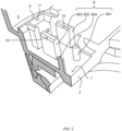
- Fig. 2 , 3 and 4 show perspective and essentially true-to-scale sections of a plastic housing 2 before inserting and connecting the contact elements 61, 62 ( Fig. 2 ); with inserted contact elements 61, 62 ( fig. 3 ) or after caulking ( Fig. 4 ).
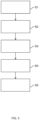
- Fig. 5 illustrates steps of a manufacturing process.
- the plastic housing 2 is formed in one piece in an injection molding process.
- the plastic housing 2 has an inner surface 7, from which projections 8 and 9 formed in one piece with the plastic housing 2 protrude vertically inwards.
- the projections 801, 802, 803, 804 are examples of the at least one plastic element 8 to be caulked.
- the projection 9 is a projection that does not need to be caulked.
- Each of the projections 8, 9 has a respective insertion bevel 14-17 at its free head end (the end remote from the inner surface 7 of the plastic housing).
- the column-shaped projection 801 has a conical tip which serves as an insertion bevel 14.
- the wall-shaped (cuboid-shaped) projections 802 and 803 have beveled edges 15, 16 at their free head ends which serve as respective insertion bevels.
- the wall-shaped, non-caulked projection 9 has a beveled edge 17 at its free head end which serves as an insertion bevel.
- the pocket 18 represents a volume area into which a contact element (61 in Fig. 3 ) and which is surrounded by various plastic elements 7, 9, 14, 15, 18 which, as described later, are caulked in order to produce a direct and positive connection with the contact element 61.
- Step S2 is carried out with reference to Fig. 5 and Fig. 1 describe.
- the ultrasonic membrane 3 is attached to the plastic housing 2 with the piezo element 4.
- the piezo element 4 is glued to the ultrasonic membrane 3.
- the ultrasonic membrane 3 is mounted in a decoupling ring 19.
- the assembly consisting of the ultrasonic membrane 3, piezo element 4 and decoupling ring 19 is arranged inside in an open side of the plastic housing 2 and mounted to the plastic housing 2 from the outside with an external cover 20.
- the connection between the external cover 20 and the plastic housing 2 is laser welded.
- step S3 The contact elements 61, 62 are inserted into the pocket 18 and thereby arranged in the interior 5 of the plastic housing 2. When inserted, the contact element 61 is guided by the insertion bevels 14-17 and positioned exactly in all degrees of freedom except for the direction of insertion.
- the contact element 61 is described as an example. It is understood that the contact element 62 is constructed in the same way.
- the contact element 61 has the contact pin section 603 running vertically upwards, the conductor rail section 601 resting on the inner surface 7 of the plastic housing 2 and the conductor rail section 601 running obliquely downwards in the direction of the ultrasonic membrane (3, Fig. 1 ) extending conductor rail section 602.
- the conductor rail section 601 has a through-opening 21 through which the column-shaped projection 801 passes precisely after the contact element 61 has been inserted.
- the conductor rail section 601 is positioned precisely between the two wall-shaped projections 802 and 803 when inserted.
- a rear side of the contact pin section 603 of the contact element 61 which runs vertically upwards, lies precisely on the projection 9, which does not need to be caulked.
- Step S4 is described with reference to Fig. 5 and Fig. 1 describe.
- the contact elements 6 are contacted with the piezo element 4.
- Step S4 does not necessarily have to take place after step S3 and/or before step S5, but can take place in whole or in part at one or more other times.
- one end of the wire 10 can advantageously be soldered to one end of the section 602 of the respective contact element 6 running diagonally downwards before insertion in step S3. After insertion in step S3, the other end of the wire 10 can then be soldered to the piezo element 4, thereby completing the contacting of the respective contact element 6 with the piezo element 4.
- the hot caulking of the projections 801-804 described below in step S5 and the soldering of the wire 10 to the piezo element 4 can take place simultaneously in one operation by inserting a stamp for caulking and a soldering tool into the plastic housing at the same time. 2 or a combination tool for chiseling and soldering is used.
- step S5 the free ends of the projections 801, 802, 803, 804 ( Fig. 3 ) is hot-stamped, and thereby a direct and positive, advantageously also force-locking, connection of the plastic housing 2 with the contact elements 61, 62 is achieved.
- the second contact element 62 shows the embodiment shown in Fig. 4 It can be seen that the column-shaped projection 804 protrudes through the through-opening 22 of the contact element 22 and the free end of the projection 804 is caulked in such a way that it engages behind the contact element 62 in a form-fitting manner. The same applies to the column-shaped projection 801 and the contact element 61.
- the free ends of the projections 802, 803 arranged on both sides of the contact element 61 which are fused during the hot caulking to form a common caulked head end of both projections 802 and 803, engage behind the contact element 61 in a form-fitting manner.
- the contact element 61 is also positioned with a precise fit in the pocket 18 formed by the projections 801, 802, 803 and deformed during the caulking and is thus directly and positively connected to the plastic housing 2.
- the manufacturing process may include further Fig. 5 include steps not shown. It is Fig. 1 Reference is made to the method described above.
- a peel test can be carried out in a further step to determine whether the connection between the contact elements 6 and the plastic housing 2 is sufficiently statically overdetermined or force-fit.
- a volume 501 of the plastic housing 2 on one side of the ultrasonic membrane 3 can then be partially cast with silicone foam in order to dampen the ultrasonic membrane.
- the circuit board 12 can then be plugged onto the contact pin section 603 and the vertical section of the contact pin 11 for external contacting.
- no casting is required.
- an upper side of the plastic housing 2 can be covered with a Cover 23 can be closed.
- the connection between cover 23 and plastic housing 2 can be laser welded, for example.
- plastic sections of the plastic housing 2 of any shape and arrangement can be caulked, as long as this creates a direct positive connection between the plastic housing 2 and the contact element 6.
Landscapes
- Engineering & Computer Science (AREA)
- Radar, Positioning & Navigation (AREA)
- Remote Sensing (AREA)
- Physics & Mathematics (AREA)
- Computer Networks & Wireless Communication (AREA)
- General Physics & Mathematics (AREA)
- Acoustics & Sound (AREA)
- Transducers For Ultrasonic Waves (AREA)
- Measurement Of Velocity Or Position Using Acoustic Or Ultrasonic Waves (AREA)
Description
- Die vorliegende Erfindung betrifft das Gebiet der Ultraschallsensorik für Fahrzeuge und speziell einen Ultraschallsendeempfänger für ein Fahrzeug und ein Herstellungsverfahren dafür.
- Bekannt sind Ultraschallsendeempfänger mit einem Gehäuse, einer an einer Öffnung des Gehäuses montierten Ultraschallmembran, einem auf die Ultraschallmembran geklebten Schallwandlerelement und einer Leiterplatte mit Elektronik zur Ansteuerung des Schallwandlerelements, die mittels Kontaktelementen mit dem Schallwandlerelement kontaktiert ist.
- Ein derartiger Ultraschallsendeempfänger kann zur Messung einer Distanz zu einem Hindernis im Fahrzeugumfeld nach dem Puls-Echo-Verfahren verwendet werden. Dabei sendet die Ultraschallmembran, angeregt von dem Schallwandlerelement, Energie in Form eines Ultraschallsignals aus. Sodann erfasst das Schallwandlerelement Schwingungen der Ultraschallmembran, die von einem aus dem Fahrzeugumfeld zurücklaufenden Echosignal herrühren. Anhand der Signallaufzeit wird die Distanz zu einem Hindernis bestimmt. Derartige Messungen werden beispielsweise von einem Parkassistenzsystem des Fahrzeugs verwendet.
- Ein Teil der ausgesendeten Ultraschall-Energie wird ins Innere des Gehäuses abgestrahlt und regt dieses zu unerwünschten Strukturschwingungen an, die zur Erfassung von Fehl- oder Geisterechos führen. Während der Ausschwingzeit der Strukturschwingungen ist daher keine sinnvolle Messung möglich. Die Distanzmessung kann somit einen Blindbereich bis in den hohen Dezimeterbereich aufweisen.
- Zur Verbesserung der Strukturdynamik eines Ultraschallsendeempfängers können die elektrischen Kontaktelemente in dem Kunststoffgehäuse umspritzt werden. Dies erfordert ein komplexes Spritzgusswerkzeug und verschlechtert die Zugänglichkeit beim elektrischen Kontaktieren der Kontaktelemente mit dem Schallwandlerelement. Die Kontaktelemente können auch im Gehäuse verpresst werden. Bei dieser Technik sind weitere Maßnahmen, wie ein Komplettverguss des Gehäuses, zur Steigerung der Belastbarkeit erforderlich.
-
EP 1 260 965 A2 ,DE 38 26 799 A1 ,DE 10 2005 009 620 A1 ,DE 10 2017 109 159 A1 undUS 2018/056901 A1 sind Beispiele für Ultraschallsendeempfänger aus dem Stand der Technik. - Vor diesem Hintergrund liegt der vorliegenden Erfindung als Aufgabe zugrunde, einen verbesserten Ultraschallsendeempfänger und ein verbessertes Herstellungsverfahren dafür bereitzustellen.
- Gemäß einem ersten Aspekt wird ein Ultraschallsendeempfänger für ein Fahrzeug vorgeschlagen, der ein Kunststoffgehäuse, eine Ultraschallmembran, ein Schallwandlerelement zur Schwingungsanregung und Schwingungserfassung der Ultraschallmembran und ein im Innenraum des Kunststoffgehäuses angeordnetes, elektrisch leitendes Kontaktelement zur elektrischen Kontaktierung des Schallwandlerelements aufweist, wobei das Kunststoffgehäuse und das Kontaktelement durch Verstemmen mindestens eines einstückig mit dem Kunststoffgehäuse ausgebildeten Kunststoffelements unmittelbar und formschlüssig miteinander verbunden sind.
- Der vorgeschlagene Ultraschallsendeempfänger kann vorteilhafterweise eine verbesserte Strukturdynamik aufweisen. Mit der vorgeschlagenen Art der Verbindung durch Verstemmen des Kunststoffgehäuses (eines einstückig mit dem Kunststoffgehäuse ausgebildeten Kunststoffelements) im Bereich des Kontaktelements können das Kontaktelement und das Kunststoffgehäuse vorteilhafterweise eine starre Einheit ausbilden, die Schwingungsenergie besser absorbieren kann. Versuche der Erfinder haben gezeigt, dass eine kürzere Ausschwingzeit von Strukturschwingungen und damit eine kürzere Blindzeit der Distanzmessung erzielt werden kann. Ferner können die Lebensdauer des Ultraschallsendeempfängers sowie die Langzeitstabilität der Ausschwingzeit erhöht werden. Ferner kann vorteilhafterweise unter Erhalt der vorgenannten Vorteile ganz oder teilweise auf einen Verguss des Kunststoffgehäuses mit Silikonschaum oder dergleichen verzichtet werden, wodurch die Masse des Ultraschallsendeempfängers gesenkt werden kann, was zu einer weiteren Verkürzung der Ausschwingzeit und Verbesserung der Strukturdynamik des Ultraschallsendeempfängers führt.
- Das Fahrzeug kann insbesondere ein Kraftfahrzeug, wie ein Personenfahrzeug oder ein Lastkraftwagen, sein. Das Fahrzeug kann insbesondere mit einem Fahrassistenzsystem und/oder einem Parkassistenzsystem ausgerüstet sein.
- Unter "Verstemmen" (engl. "heat staking") ist insbesondere ein thermoplastisches Warm- bzw. Heißverstemmen zu verstehen. Insbesondere ist unter "Verstemmen" ein Vorgang zu verstehen, bei dem ein Abschnitt des Kunststoffelements unter Wärmezufuhr thermoplastisch verformt wird und dabei unter Einwirkung eines Stemmmittels eine mindestens formschlüssige, vorzugsweise kraftschlüssige, Verbindung zwischen dem Kunststoffgehäuse bzw. dem verformten Kunststoffelement und dem Kontaktelement geschaffen wird. Das Stemmmittel kann ein Stempel sein. Weitere Beispiele für ein Stemmmittel sind Laserstrahlung oder Infrarotstrahlung.
- Das Kunststoffelement ist einstückig mit dem Kunststoffgehäuse ausgebildet. Insbesondere sind das Kunststoffelement und das Kunststoffgehäuse durch Urformen, wie beispielsweise Spritzgießen, in einem Arbeitsgang als ein durchgängiges Element ausgebildet. Das Kunststoffelement ist insbesondere im Innenraum des Kunststoffgehäuses angeordnet. Das Kunststoffelement kann als ein Abschnitt des Kunststoffgehäuses betrachtet werden. Insbesondere kann vorliegend von "Verstemmen des Kunststoffgehäuses" oder "Verstemmen eines Abschnitts des Kunststoffgehäuses" gesprochen werden, womit ein "Verstemmen des Kunststoffelements" bzw. eines Abschnitts desselben gemeint sein kann
- Das Kunststoffelement kann beispielsweise ein nach innen ragender Vorsprung des Kunststoffgehäuses sein, wie beispielsweise ein Kunststoffdom oder dergleichen.
- Unter "formschlüssig verbunden" ist vorliegend eine Verbindung durch Ineinander- oder Hintergreifen mindestens zweier Verbindungspartner zu verstehen.
- Unter "unmittelbar verbunden" ist vorliegend zu verstehen, dass kein von den Verbindungspartnern verschiedenes weiteres Verbindungselement, wie eine Schraube oder dergleichen, zur Verbindung verwendet wird.
- Insbesondere sind das Kunststoffgehäuse (ein Verbindungspartner) und das Kontaktelement (anderer Verbindungspartner) dadurch unmittelbar verbunden, dass das Kunststoffgehäuse (das einteilig damit ausgebildete Kunststoffelement) geeignet verstemmt ist.
- Das Schallwandlerelement kann insbesondere ein Piezoelement oder ein Ultraschall-Transducer sein. Das Schallwandlerelement kann auf die Ultraschallemembran geklebt, mit dieser verschweißt oder auf andere Weise mit der Ultraschallmembran verbunden sein.
- Unter "Kontaktelement zur elektrischen Kontaktierung des Schallwandlerelements" ist insbesondere zu verstehen, dass an das Kontaktelement ein elektrisches Signal angelegt werden kann, um das Schallwandlerelement dazu zu veranlassen, die Ultraschallmembran zu Schwingungen anzuregen, um ein Ultraschallsignal auszusenden, und/oder, dass an dem Kontaktelement ein elektrisches Signal bezogen werden kann, welches für von dem Schallwandlerelement erfasste Schwingungen der Ultraschallmembran indikativ ist, um ein reflektiertes Echosignal zu erfassen. Das Kontaktelement kann direkt oder indirekt mit dem Schallwandlerelement kontaktiert sein. Insbesondere wird aus Gründen der Schallentkopplung ein indirekter Kontakt mit dem Schallwandlerelement bevorzugt. Das Kontaktelement kann einen oder mehrere Abschnitte umfassen, die als Kontaktstift, Leiterelement, Leiterschiene und dergleichen ausgebildet sein können. Das Kontaktelement kann insbesondere ein metallisches Element sein.
- Der Begriff "ein" ist vorliegend, sofern nicht anders angegeben, nicht auf die Auslegung "genau ein" eingeschränkt, und kann insbesondere auch die Bedeutung "mehrere" umfassen. Insbesondere versteht sich, dass in dem Kunststoffgehäuse auch zwei oder mehr Kontaktelemente vorgesehen sein können, die jeweils auf gleiche Weise, wie für das "eine" Kontaktelemente beschrieben, mit dem Kunststoffgehäuse verbunden sein können.
- Gemäß einer Ausführungsform besteht zwischen dem Kunststoffgehäuse und dem Kontaktelement eine Zwängung.
- Somit ist die durch Verstemmen des mindestens einen Kunststoffelements hergestellte Verbindung zwischen Kunststoffgehäuse und Kontaktelement vorzugsweise nicht nur formschlüssig, sondern auch kraftschlüssig. Insbesondere wirkt eine Normalkraft auf die miteinander zu verbindenden Flächen des Kunststoffgehäuses bzw. des Kunststoffelements und des Kontaktelements. Insbesondere ist die Verbindung zwischen Kunststoffgehäuse und Kontaktelement statisch überbestimmt. Die Stärke der Zwängung kann unter Berücksichtigung der im Betrieb zu erwartenden Vibrationen aufgrund ausgesandter und empfangener Ultraschallsignale, Fahrbewegungen des Fahrzeugs und dergleichen gewählt werden. Das Vorliegen einer geeigneten Zwängung kann durch einen Abziehtest überprüft werden. Die Güte der Verstemmung kann aus den Parametern der Verstemmaschine überwacht werden. Auch ist möglich die Güte der Verstemmung mit einer Kamera optisch zu prüfen.
- Gemäß einer Ausführungsform ist das Kontaktelement ein starres Element, und ein elektrischer Kontakt zwischen dem Kontaktelement und dem Schallwandlerelement ist über ein flexibles Zwischenelement hergestellt.
- Das heißt, gemäß der vorliegenden Ausführungsform kontaktiert das Kontaktelement das Schallwandlerelement indirekt über das Zwischenelement. Das flexible Zwischenelement ist mindestens flexibler als das starre Kontaktelement. Das flexible Zwischenelement kann ein geringeres Gewicht und einen geringeren Querschnitt als das starre Kontaktelement aufweisen. Das flexible Zwischenelement kann vorzugsweise ein Draht sein. Der Draht kann länger gewählt sein als ein Abstand zwischen dem Kontaktelement und dem Schallwandlerelement, und kann demgemäß nicht straff gespannt sein.
- Auf diese Weise kann vorteilhafterweise das starre Kontaktelement von der schwingenden Ultraschallmembran akustisch entkoppelt werden.
- Gemäß einer Ausführungsform umfasst das mindestens eine verstemmte Kunststoffelement einen Vorsprung, der von dem Kunststoffgehäuse nach innen ragt, durch eine Durchgangsöffnung in dem Kontaktelement verläuft, und dessen freies Kopfende dergestalt verstemmt ist, dass es das Kontaktelement formschlüssig hintergreift.
- Unter "freiem Kopfende" des Vorsprungs ist insbesondere ein von dem Kunststoffgehäuse entfernte Endes des Vorsprungs zu verstehen.
- Bei der Herstellung des vorgeschlagenen Ultraschallsendeempfängers ermöglicht die vorliegende Ausführungsform vorteilhafterweise ein exaktes Positionieren des Kontaktelements. Der Vorsprung kann in die Durchgangsöffnung eingeführt werden, und anschließend kann das freie Kopfende durch Verstemmen beispielsweise pilzkopfförmig aufgeweitet werden. Somit kann ein stabiler formschlüssiger Sitz des Kontaktelements zwischen dem verstemmten freien Kopfende des Vorsprungs und dem Kunststoffgehäuse erzielt werden.
- Gemäß einer weiteren Ausführungsform umfasst das mindestens eine verstemmte Kunststoffelement mindestens zwei Vorsprünge, die von dem Kunststoffgehäuse nach innen ragen, wobei das Kontaktelement zwischen den mindestens zwei Vorsprüngen angeordnet ist, und wobei die freien Kopfenden der Vorsprünge dergestalt verstemmt sind, dass sie das Kontaktelement formschlüssig hintergreifen.
- Unter "freiem Kopfende" eines jeweiligen Vorsprungs ist insbesondere das von dem Kunststoffgehäuse entfernte Ende des Vorsprungs zu verstehen.
- Bei der Herstellung des vorgeschlagenen Ultraschallsendeempfängers kann die vorliegende Ausführungsform ein exaktes Positionieren des Kontaktelements zwischen den beiden Vorsprüngen ermöglichen. Das Kontaktelement kann zwischen die beiden Vorsprünge gelegt werden und anschließend können deren freien Kopfende durch Verstemmen aufgeweitet werden. Somit kann ein stabiler Sitz des Kontaktelements zwischen den verstemmten freien Kopfenden der beiden Vorsprünge und dem Kunststoffgehäuse erzielt werden.
- Gemäß einer weiteren Ausführungsform umfasst das Kontaktelement einen schienenförmigen Abschnitt, und die unmittelbare formschlüssige Verbindung ist zwischen dem verstemmten Kunststoffelement und dem schienenförmigen Abschnitt hergestellt.
- Der schienenförmige Abschnitt kann auf einer Innenoberfläche des Kunststoffgehäuses aufliegen und formschlüssig zwischen der Innenoberfläche des Kunststoffgehäuses und dem mindestens einen verstemmten Kunststoffelement eingefasst sein.
- Gemäß einer weiteren Ausführungsform umfasst das Kontaktelement einen stiftförmigen Abschnitt, und eine Leiterplatte mit mindestens einem elektronischen Bauelement zum Ansteuern des Schallwandlerelements ist auf den stiftförmigen Abschnitt gesteckt.
- Dank der durch Verstemmen hergestellten unmittelbaren formschlüssigen Verbindung zwischen dem durch das Zwischenelement akustisch entkoppelten Kontaktelement und Kunststoffgehäuse ist vorteilhafterweise zwischen der Leiterplatte und dem stiftförmigen Abschnitt des Kontaktelements eine Steckverbindung ausreichend. Die Steckverbindung braucht nicht vergossen zu werden. Somit kann vorteilhafterweise die Montage und ggf. die Reparatur bzw. der Austausch der Leiterplatte vereinfacht werden.
- Gemäß einer weiteren Ausführungsform verläuft die Leiterplatte parallel zu der Ultraschallmembran, ein Volumen des Innenraums des Kunststoffgehäuses auf einer der Ultraschallmembran zugewandten Seite der Leiterplatte ist mit einem Schaum vergossen, und ein Volumen des Innenraums auf einer der Ultraschallmembran abgewandten Seite der Leiterplatte ist frei von Schaumverguss.
- Der Schaum kann beispielsweise ein Silikonschaum sein. Das Volumen des Innenraums des Kunststoffgehäuses auf der der Ultraschallmembran zugewandten Seite kann ganz oder teilweise mit dem Schaum vergossen sein. Insbesondere kann ein Volumenbereich des Innenraums des Kunststoffgehäuses mit Schaum vergossen sein, der an die Ultraschallmembran angrenzt. Somit kann die Ultraschallmembran vorteilhaft gedämpft werden.
- Gleichzeitig ist mindestens ein Volumenbereich des Kunststoffbereichs auf der der Ultraschallmembran abgewandten Seite der Leiterplatte frei von Schaum. Optional ist auch ein Teil eines Volumenbereichs auf der der Ultraschallmembran zugewandten Seite frei von Schaum. Insbesondere ist es gemäß der vorgeschlagenen Lösung nicht erforderlich, die Verbindung zwischen Leiterplatte und stiftförmigem Abschnitt des Kontaktelements zu vergießen. Ebenso ist es nicht notwendigerweise erforderlich, die Verbindung zwischen dem schienenförmigen Abschnitt des Kontaktelements und dem Kunststoffgehäuse zu vergießen.
- Es kann somit vorteilhafterweise Vergussmasse eingespart und die Masse des Ultraschallsendeempfängers verringert werden. Dies kann sich vorteilhaft auf die Strukturdynamik und insbesondere auf die Ausschwingzeit des Ultraschallsendeempfängers auswirken.
- Gemäß einem zweiten Aspekt wird ein Verfahren zum Herstellen eines Ultraschallsendeempfängers für ein Fahrzeug vorgeschlagen. Das Verfahren umfasst die Schritte: Ausbilden eines Kunststoffgehäuses mit mindestens einem einstückig mit dem Kunststoffgehäuse ausgebildeten Kunststoffelement; Befestigen einer Ultraschallmembran mit einem Schallwandlerelement zur Schwingungsanregung und Schwingungserfassung der Ultraschallmembran an dem Kunststoffgehäuse; Anordnen eines elektrisch leitenden Kontaktelements im Innenraum des Kunststoffgehäuses; Kontaktieren des Kontaktelements mit dem Schallwandlerelement; und unmittelbares und formschlüssiges Verbinden des Kunststoffgehäuses mit dem Kontaktelement durch Verstemmen des mindestens einen einstückig mit dem Kunststoffgehäuse ausgebildeten Kunststoffelements.
- Die vorstehend für den Ultraschallsendeempfänger des ersten Aspekts beschriebenen Merkmale, Vorteile, Definitionen und Ausführungsformen gelten entsprechend auch für das Herstellungsverfahren des zweiten Aspekts. Die nachstehend für das Herstellungsverfahren des zweiten Aspekts beschriebenen Merkmale, Vorteile, Definitionen und Ausführungsformen gelten entsprechend auch für den Ultraschallsendeempfänger des ersten Aspekts.
- Das vorgeschlagene Herstellungsverfahren kann vorteilhafterweise eine verbesserte Zugänglichkeit bieten und dadurch die Montage vereinfachen. So kann ein Spritzgusswerkzeug zum Urformen des Kunststoffgehäuses kompakter und einfacher gestaltet sein, und das Kontaktieren des Kontaktelements mit dem Schallwandlerelement kann mindestens teilweise unter erheblich mehr Bewegungsfreiheit bereits vor dem Anordnen des Kontaktelements im Kunststoffgehäuse und vor dem Verbinden des Kunststoffgehäuses mit dem Kontaktelement erfolgen. Beispielsweise kann ein Draht als Zwischenelement bereits vor dem Anordnen des Kontaktelements in dem Kunststoffgehäuse mit dem Kontaktelement verlötet werden.
- Das Ausbilden des Kunststoffgehäuses mit dem einstückig damit ausgebildeten Kunststoffelement kann ein Urformen, wie zum Beispiel Spritzgießen, in einem Arbeitsgang umfassen.
- Das Befestigen der Ultraschallmembran mit dem Schallwandlerelement kann insbesondere folgende Schritte umfassen: Kleben des Schallwandlerelements auf die Ultraschallmembran; und Montieren der Ultraschallmembran mit dem Schallwandlerelement an dem Gehäuse.
- Das Anordnen des Kontaktelements kann insbesondere ein Legen des Kontaktelements auf eine Innenoberfläche des Kunststoffgehäuses umfassen.
- Das Kontaktieren des Kontaktelements mit dem Schallwandlerelement kann insbesondere ein Löten umfassen.
- Das Verstemmen des mindestens einen Kunststoffelements kann insbesondere ein thermoplastisches Verformen des mindestens einen Kunststoffelements unter Wärmezufuhr umfassen, dergestalt, dass nach Abkühlung des Kunststoffs eine formschlüssige Verbindung zwischen dem Kunststoffgehäuse, dem verstemmten Kunststoffelement und dem Kontaktelement besteht.
- Gemäß einer Ausführungsform wird das Kunststoffgehäuse einstückig mit dem mindestens einem Kunststoffelement ausgebildet, das mindestens einen Vorsprung umfasst, der von dem Kunststoffgehäuse nach innen ragt und an seinem freien Kopfende eine Einführschräge aufweist, und das Kontaktelement wird beim Anordnen in dem Innenraum des Kunststoffgehäuses von der Einführschräge geführt und positioniert.
- Beispielsweise kann die Einführschräge durch eine abgeschrägte obere Kante eines quaderförmigen Vorsprungs gebildet sein. Die Einführschräge kann auch durch eine konische Spitze eines zylinderförmigen Vorsprungs gebildet sein.
- Die Einführschräge kann vorteilhafterweise das Positionieren des Kunststoffelements beim vorzugsweise automatisch ausgeführten Anordnen in dem Kunststoffgehäuse unterstützen.
- Gemäß einer Ausführungsform umfasst das mindestens eine einstückig mit dem Kunststoffgehäuse ausgebildete Kunststoffelement mehrere Vorsprünge, die von dem Kunststoffgehäuse nach innen ragen, an ihren freien Kopfenden eine jeweilige Einführschräge aufweisen und gemeinsam eine Tasche ausbilden, wobei das Anordnen des elektrisch leitenden Kontaktelements im Innenraum des Kunststoffgehäuses ein Einlegen des Kontaktelements in die Tasche umfasst, wobei das Kontaktelement beim Einlegen von den Einführschrägen geführt und positioniert wird.
- Unter einer "Tasche" ist insbesondere ein im Wesentlichen quaderförmiges Volumen zu verstehen, das durch das Kunststoffgehäuse und die jeweiligen Vorsprünge definiert ist und passgenau konform zu den in die Tasche einzulegenden Kontaktelementen ausgebildet ist. Das als "Tasche" bezeichnete Volumen ist nicht notwendigerweise vollständig von Kunststoffelementen umgeben, sondern kann an jeder seiner Seiten Lücken aufweisen.
- Beim Herstellen des Ultraschallsendeempfängers kann auf diese Weise das Kontaktelement auf einfache Weise, insbesondere automatisch durch einen Roboterarm, in die von den Vorsprüngen gebildete Tasche eingelegt und dabei von den Einführschrägen an den freien Kopfenden der Vorsprünge automatisch und vorzugsweise in allen Freiheitsgraden mit Ausnahme der Richtung des Einlegens exakt positioniert werden.
- Gemäß einer weiteren Ausführungsform ist das Kontaktelement ein starres Element, und ein elektrischer Kontakt zwischen dem Kontaktelement und dem Schallwandlerelement wird über ein flexibles Zwischenelement hergestellt.
- Demgemäß kann vorteilhafterweise das Kontaktelement akustisch von dem Schallwandlerelement und damit auch von der Ultraschallmembran entkoppelt werden.
- Gemäß einer weiteren Ausführungsform umfasst das Kontaktieren des Kontaktelements mit dem Schallwandlerelement ein Verlöten oder Verscheißen eines Endes des flexiblen Zwischenelements mit dem Kontaktelement vor dem Anordnen des Kontaktelements in dem Kunststoffgehäuse und ein Verlöten oder Verscheißen des anderen Endes des flexiblen Zwischenelements mit dem Schallwandlerelement nach dem Anordnen des Kontaktelements in dem Kunststoffgehäuse.
- Da das Verbinden des Kontaktelements mit dem Kunststoffgehäuse durch Verstemmen eines Kunststoffelements erfolgt, kann das Verlöten bzw. das Verschweißen mindestens des einen Endes des flexiblen Zwischenelements schon vor dem Anordnen des Kontaktelements erfolgen, wo vorteilhafterweise mehr Bewegungsfreiheit besteht, was ein exakteres Arbeiten ermöglicht.
- Gemäß einer weiteren Ausführungsform erfolgen das Verlöten oder das Verschweißen des anderen Endes des flexiblen Zwischenelements mit dem Schallwandlerelement und das Verstemmen des mindestens einen Kunststoffelements gleichzeitig in einem Arbeitsgang.
- Gemäß einer weiteren Ausführungsform umfasst das Kontaktieren des Kontaktelements mit dem Schallwandlerelement ein Verlöten oder Verscheißen eines Endes des flexiblen Zwischenelements mit dem Kontaktelement und ein Verlöten oder Verscheißen des anderen Endes des flexiblen Zwischenelements mit dem Schallwandlerelement nach dem Verstemmen des Kunststoffelements zur Verbindung des Kontaktelements mit dem Kunststoffgehäuse.
- Das vorgeschlagene Verbinden von Kontaktelement und Kunststoffgehäuse durch Verstemmen macht die Verwendung komplexer Spritzgusswerkzeuge oder dergleichen überflüssig und kann platzsparend erfolgen, so dass gleichzeitig mit einem Stempel zum Verstemmen auch ein Lötwerkzeug in das Kunststoffgehäuse eingebracht werden oder ein Kombiwerkzeug zum Löten und zum Verstemmen benutzt werden kann. Der Energie- und Zeitaufwand bei der Montage des Ultraschallsendeempfängers kann so vorteilhaft verringert werden.
- Weitere vorteilhafte Ausgestaltungen und Aspekte der Erfindung sind Gegenstand der Unteransprüche sowie der im Folgenden beschriebenen Ausführungsbeispiele der Erfindung. Im Weiteren wird die Erfindung anhand von bevorzugten Ausführungsbeispielen unter Bezugnahme auf die beigefügten Figuren näher erläutert.
- Fig. 1
- zeigt eine schematische Schnittansicht eines Ultraschallsendeempfängers gemäß einem ersten Ausführungsbeispiel;
- Fig. 2
- zeigt einen perspektivischen Ausschnitt eines Kunststoffgehäuses vor dem Einlegen und Verbinden der Kontaktelemente gemäß einem zweiten Ausführungsbeispiel;
- Fig. 3
- zeigt einen perspektivischen Ausschnitt des Kunststoffgehäuses aus
Fig. 2 mit eingelegten Kontaktelementen; - Fig. 4
- zeigt einen perspektivischen Ausschnitt des Kunststoffgehäuses aus
Fig. 3 nach dem Verstemmen; und - Fig. 5
- zeigt Schritte eines Herstellungsverfahrens gemäß einem Ausführungsbeispiel.
- In den Figuren sind gleiche oder funktionsgleiche Elemente mit denselben Bezugszeichen versehen worden, sofern nichts anderes angegeben ist.
-
Fig. 1 zeigt eine schematische und nicht maßstabsgetreue Schnittansicht eines Ultraschallsendeempfängers 1 gemäß einem ersten Ausführungsbeispiel. - Der Ultraschallsendeempfänger 1 umfasst ein Kunststoffgehäuse 2. In einer offenen Unterseite des Kunststoffgehäuses 2 ist eine Ultraschallmembran 3 zum Aussenden und Empfangen von Ultraschallsignalen montiert. Auf die Ultraschallmembran 3 ist ein Piezoelement 4 (Beispiel für ein Schallwandlerelement) geklebt. Das Piezoelement 4 ist dazu eingerichtet, gesteuert von einem elektrischen Signal die Ultraschallmembran 3 zu Schwingungen anzuregen, und ist dazu eingerichtet, Schwingungen der Ultraschallmembran 3 zu erfassen und in ein elektrisches Signal zu wandeln. Im Innenraum 5 des Kunststoffgehäuses 2 ist ein elektrisch leitendes Kontaktelement 6 zur Kontaktierung des Piezoelements 4 angeordnet. Ein horizontaler Abschnitt 601 des Kontaktelements 6 ruht auf einer Innenoberfläche 7 des Kunststoffgehäuses 2. Das Kontaktelement 6 (der horizontale Abschnitt 601) ist dadurch unmittelbar und formschlüssig mit dem Kunststoffgehäuse 2 verbunden, dass ein freies Kopfende eines Kunststoffelements 8, das einstückig mit dem Kunststoffgehäuse 2 ausgebildet ist, verstemmt ist (in
Fig. 1 durch eine beispielhafte Pilzkopfform angedeutet). - Es sei angemerkt, dass das Kunststoffelement 8 ebenfalls als Abschnitt des Kunststoffgehäuses 2 angesehen wird, da es einstückig mit dem Kunststoffgehäuse 2 ausgebildet ist. Anders ausgedrückt ist das Kunststoffgehäuse 2 in einem Bereich des Kontaktelements 6 dergestalt verstemmt, dass Abschnitte 7, 8 des Kunststoffgehäuses 2 und das Kontaktelement 6 unmittelbar und formschlüssig miteinander verbunden sind.
- Der Ultraschallsendeempfänger 1 weist eine vorteilhafte Strukturdynamik, eine verringerte Abklingzeit von Strukturschwingungen, eine erhöhte Lebensdauer und eine höhere Langzeitstabilität der Abklingzeit auf.
- Weiter unter Bezugnahme auf
Fig. 1 werden vorteilhafte Ausgestaltungen und Weiterbildungen des Ultraschallsendeempfängers 1 beschreiben. - Insbesondere besteht zwischen dem Kunststoffgehäuse 2, insbesondere zwischen der Innenoberfläche 7 und dem verstemmten freien Ende des Kunststoffelements 8, und dem Kontaktelement 6 (Abschnitt 601), eine Zwängung. Zum einen kann es aufgrund von Fertigungstoleranzen schwierig sein, eine statische Bestimmtheit der Verbindung zwischen Kunststoffgehäuse 2 und Kontaktelement 6 zu erreichen. Durch Wahl einer zumindest geringfügigen Zwängung lässt sich eine statische Überbestimmtheit sicherstellen. Zum anderen kann somit die Verbindung zwischen Kunststoffgehäuse 2 und Kontaktelement 6 nicht nur formschlüssig, sondern auch kraftschlüssig ausgebildet sein.
- Insbesondere ist das zumindest formschlüssig mit dem Kunststoffgehäuse 2 verbundene Kontaktelement 6 nicht direkt mit dem Piezoelement 4 verbunden. Zwischen dem starren Kontaktelement 6 und dem Piezoelement 4 ist ein flexibler, dünner Draht 10 (Beispiel für ein Zwischenelement) angeordnet. Der Draht 10 dient der akustischen Entkopplung des Kontaktelements 6 von der Ultraschallmembran 3.
- Insbesondere ist die Ultraschallmembran 3 nicht direkt mit dem Kunststoffgehäuse 2 verbunden. Die Ultraschallmembran 3 ist beispielsweise in einem Entkopplungsring 19 (auch als "Plug" bezeichnet) angebracht. Die Baugruppe aus Ultraschallmembran 3, Piezoelement 4 und Entkopplungsring 19 ist innenliegend in einer offenen Seite des Kunststoffgehäuses 2 angeordnet und mittels eines außenliegenden ringförmigen Deckels 20 an dem Kunststoffgehäuse 2 montiert. Die Verbindung von Deckel 20 und Kunststoffgehäuse 2 kann laserverschweißt sein. Dergestalt kann eine akustische Entkopplung des Kunststoffgehäuses 2 von der Ultraschallmembran 3 mit dem Piezoelement 4 erzielt werden.
- Insbesondere ist der mit dem Kunststoffgehäuse 2 formschlüssig verbundene horizontale Abschnitt 601 ein Leiterschienenabschnitt (schienenförmiger Abschnitt), der flach auf der Innenoberfläche 7 des Kunststoffgehäuses 2 aufliegt. Außerdem umfasst das Kontaktelement 6 einen weiteren Leiterschienenabschnitt 602, der schräg nach unten in Richtung des Piezoelements 4 verläuft. Außerdem umfasst das Kontaktelement 6 einen Kontaktstiftabschnitt 603 (stiftförmiger Abschnitt), der im Wesentlichen orthogonal zu dem Leiterschienenabschnitt 601 nach oben verläuft. Der vertikal nach oben verlaufende Kontaktstiftabschnitt 603 liegt passgenau an einem nicht verstemmten, einstückig mit dem Kunststoffgehäuse 2 ausgebildeten und nach innen ragenden Vorsprung 9 an.
- Mit "unten" wird vorliegend eine Richtung entlang einer Hauptachse des Ultraschallsendeempfängers 1 bezeichnet, entlang derer Ultraschallsignale ausgesendet werden können, und mit "oben" entsprechend die entgegengesetzte Richtung. Es versteht sich, dass der Ultraschallsendeempfänger 1 in jeder beliebigen Orientierung an einem Fahrzeug montiert werden kann und weder bei der Herstellung des Ultraschallsendeempfängers 1 noch im Betrieb des Ultraschallsendeempfängers 1 die Richtung nach "unten" notwendigerweise oder vorzugsweise mit einer Schwerkraftrichtung übereinzustimmen braucht.
- Insbesondere weist der Ultraschallsendeempfänger 2 einen weiteren Kontaktstift 11 zum externen Kontaktieren auf, der aus einem Hauptgehäuseabschnitt 201 des Kunststoffgehäuses 2 in einen Kupplungsgehäuseabschnitt 202 des Kunststoffgehäuses 2 geführt ist und der externen Kontaktierung dient. Ein Abschnitt des weiteren Kontaktstifts 11 ragt im Hauptgehäuseabschnitt 201 des Kunststoffgehäuses auf einer dem Kontaktstiftabschnitt 603 des Kontaktelements 6 gegenüberliegenden Seite und parallel zu diesem vertikal nach oben.
- Eine Leiterplatte 12 ist von oben auf den Kontaktstiftabschnitt 603 des Kontaktelements 6 zur Kontaktierung des Piezoelements 4 und auf den vertikalen Abschnitt des weiteren Kontaktstifts 11 zur externen Kontaktierung gesteckt. Auf der Leiterplatte 12 sind ein oder mehrere elektronische Bauelemente 13 zum Ansteuern des Piezoelements 4 angeordnet.
- Insbesondere kann vorzugsweise ein Volumen 501 des Innenraums 5 des Kunststoffgehäuses 2 auf einer der Ultraschallmembran 3 zugewandten Seite der Leiterplatte 12 zumindest teilweise mit einem Silikonschaum vergossen sein. Besonders bevorzugt kann das Volumen 501 ausgehend von der Ultraschallmembran 3 bis zu einer Höhe mit dem Silikonschaum vergossen sein, die ausreichend ist, um für eine ausreichende Dämpfung der Ultraschallmembran 3 zu sorgen, aber unterhalb der Leiterplatte 12 liegt. Insbesondere ist es vorteilhafterweise nicht erforderlich, die durch Verstemmen gebildete Verbindung zwischen dem Leiterschienenabschnitt 601 des Kontaktelements 6 und dem verstemmten Kunststoffelement 8 mit dem Silikonschaum zu vergießen. Ebenfalls ist es nicht erforderlich, die Steckverbindung zwischen dem Kontaktstiftabschnitt 603 des Kontaktelements 6 und der Leiterplatte 12 mit dem Silikonschaum zu vergießen. Insbesondere ist ein Volumen 502 auf einer der Ultraschallmembran 3 abgewandten Seite der Leiterplatte 12 frei von Schaumverguss. Auf diese Weise kann somit vorteilhafterweise die Menge an verwendetem Silikonschaum im Vergleich zu einem vollständigen Vergießen des Kunststoffgehäuses 2 auf das zur Dämpfung der Ultraschallmembran 3 notwendige Mindestmaß reduziert werden. Dadurch kann die Gesamtmasse des Ultraschallsendeempfängers 1 verringert werden, was sich vorteilhaft auf die Strukturdynamik und die Abklingzeit von Strukturschwingungen auswirken kann.
- Im Folgenden werden anhand der
Fig. 2 bis 5 ein Herstellungsverfahren für einen Ultraschallsendeempfänger 1 sowie ein Ultraschallsendeempfänger 1 gemäß einem zweiten Ausführungsbeispiel beschrieben. Das zweite Ausführungsbeispiel ist mit dem ersten Ausführungsbeispiel kompatibel. Gleiche Elemente tragen gleiche Bezugszeichen und werden nicht erneut beschrieben. -
Fig. 2 ,3 und4 zeigen perspektivische und im Wesentlichen maßstabsgetreue Ausschnitte eines Kunststoffgehäuses 2 vor dem Einlegen und Verbinden der Kontaktelemente 61, 62 (Fig. 2 ); mit eingelegten Kontaktelementen 61, 62 (fig. 3 ) bzw. nach dem Verstemmen (Fig. 4 ).Fig. 5 veranschaulicht Schritte eines Herstellungsverfahrens. - In Schritt S1 wird das Kunststoffgehäuse 2 in einem Spritzgussvorgang einstückig ausgebildet. Das Kunststoffgehäuse 2 weist eine Innenoberfläche 7 auf, von der einstückig mit dem Kunststoffgehäuse 2 ausgebildete Vorsprünge 8 und 9 vertikal nach innen ragen. Die Vorsprünge 801, 802, 803, 804 sind Beispiele für das mindestens eine zu verstemmende Kunststoffelement 8. Der Vorsprung 9 ist ein nicht zu verstemmender Vorsprung.
- Jeder der Vorsprünge 8, 9 weist an seinem an seinem freien Kopfende (dem von der Innenoberfläche 7 des Kunststoffgehäuses entfernten Ende) eine jeweilige Einführschräge 14-17 auf. Im Speziellen weist der säulenförmige Vorsprung 801 eine konische Spitze auf, die als Einführschräge 14 dient. Die wandförmigen (quaderförmigen) Vorsprünge 802 und 803 weisen an ihren freien Kopfenden abgeschrägte Kanten 15, 16 auf, die als jeweilige Einführschrägen dienen. Der wandförmige, nicht zu verstemmende Vorsprung 9 weist an seinem freien Kopfende eine abgeschrägte Kante 17 auf, die als eine Einführschräge dient.
- Der säulenförmige Vorsprung 801, die wandförmigen Vorsprünge 802, 803 und der nicht zu verstemmende Vorsprung 9 bilden gemeinsam eine Tasche 18 aus. Die Tasche 18 stellt einen Volumenbereich dar, in den ein Kontaktelement (61 in
Fig. 3 ) eingelegt werden kann und das von unterschiedlichen Kunststoffelementen 7, 9, 14, 15, 18 umgeben ist, die, wie später beschrieben, verstemmt werden, um eine unmittelbare und formschlüssige Verbindung mit dem Kontaktelement 61 herzustellen. - Schritt S2 wird unter Bezug auf
Fig. 5 undFig. 1 beschreiben. In Schritt S2 wird die Ultraschallmembran 3 mit dem Piezoelement 4 an dem Kunststoffgehäuse 2 befestigt. Insbesondere wird das Piezoelement 4 auf die Ultraschallmembran 3 geklebt. Die Ultraschallmembran 3 wird in einem Entkopplungsring 19 angebracht. Die Baugruppe aus Ultraschallmembran 3, Piezoelement 4 und Entkopplungsring 19 wird innenliegend in einer offenen Seite des Kunststoffgehäuses 2 angeordnet und mit einem außenliegenden Deckel 20 von außen an dem Kunststoffgehäuse 2 montiert. Die Verbindung zwischen außenliegendem Deckel 20 und Kunststoffgehäuse 2 wird laserverschweißt. - Es wird nun auf
Fig. 3 und5 Bezug genommen. In Schritt S3 werden die Kontaktelemente 61, 62 in die Tasche 18 eingelegt und dadurch im Innenraum 5 des Kunststoffgehäuses 2 angeordnet. Beim Einlegen wird das Kontaktelement 61 von den Einführschrägen 14-17 geführt und in allen Freiheitsgraden außer der Richtung des Einlegens exakt positioniert. - Beispielhaft wird das Kontaktelement 61 beschrieben. Es versteht sich, dass das Kontaktelement 62 gleichartig aufgebaut ist. Das Kontaktelement 61 weist den vertikal nach oben verlaufenden Kontaktstiftabschnitt 603, den auf der Innenoberfläche 7 des Kunststoffgehäuses 2 ruhenden Leiterschienenabschnitt 601 und den schräg nach unten in Richtung der Ultraschallmembran (3,
Fig. 1 ) verlaufenden Leiterschienenabschnitt 602 auf. Der Leiterschienenabschnitt 601 weist eine Durchgangsöffnung 21 auf, durch welche der säulenförmige Vorsprung 801 nach dem Einlegen des Kontaktelements 61 passgenau hindurch verläuft. Der Leiterschienenabschnitt 601 wird beim Einlegen passgenau zwischen den beiden wandförmigen Vorsprüngen 802 und 803 positioniert. Zudem kommt eine Rückseite des vertikal nach oben verlaufenden Kontaktstiftabschnitts 603 des Kontaktelements 61 passgenau an dem nicht zu verstemmenden Vorsprung 9 zu liegen. - Schritt S4 wird unter Bezug auf
Fig. 5 undFig. 1 beschreiben. In Schritt S4 werden die Kontaktelemente 6 mit dem Piezoelement 4 kontaktiert. Schritt S4 braucht nicht notwendigerweise zeitlich nach Schritt S3 und/oder zeitlich vor Schritt S5 zu erfolgen, sondern kann ganz oder teilweise zu einem oder mehreren anderen Zeitpunkten erfolgen. Beispielsweise kann vorteilhafterweise ein Ende des Drahts 10 bereits vor dem Einlegen in Schritt S3 mit einem Ende des schräg nach unten verlaufenden Abschnitts 602 des jeweiligen Kontaktelements 6 verlötet werden. Nach dem Einlegen in Schritt S3 kann sodann das andere Ende des Drahts 10 mit dem Piezoelement 4 verlötet und dadurch das Kontaktieren des jeweiligen Kontaktelements 6 mit dem Piezoelement 4 abgeschlossen werden. Besonders bevorzugt können das nachstehend beschriebene Heißverstemmen der Vorsprünge 801-804 in Schritt S5 und das Verlöten des Drahts 10 mit dem Piezoelement 4 gleichzeitig in einem Arbeitsgang erfolgen, indem ein Stempel zum Verstemmen und ein Lötwerkzeug gleichzeitig in das Kunststoffgehäuse 2 eingeführt werden oder ein Kombiwerkzeug zum Stemmen und Löten verwendet wird. - Es wird nun auf
Fig. 3 bis Fig. 5 Bezug genommen. In Schritt S5 werden die freien Enden der Vorsprünge 801, 802, 803, 804 (Fig. 3 ) heißverstemmt, und dadurch wird eine unmittelbare und formschlüssige, vorteilhafterweise außerdem kraftschlüssige, Verbindung des Kunststoffgehäuses 2 mit den Kontaktelementen 61, 62 erzielt. Es ergibt sich die inFig. 4 gezeigte Ausgestaltung. Anhand des zweiten Kontaktelements 62 ist inFig. 4 zu sehen, dass der säulenförmige Vorsprung 804 durch die Durchgangsöffnung 22 des Kontaktelements 22 ragt und das freie Ende des Vorsprungs 804 dergestalt verstemmt ist, dass es das Kontaktelement 62 formschlüssig hintergreift. Entsprechendes gilt für den säulenförmigen Vorsprung 801 und das Kontaktelement 61. Außerdem hintergreifen die freien Enden der zu beiden Seiten des Kontaktelements 61 angeordneten Vorsprünge 802, 803, die bei dem Heißverstemmen zu einem gemeinsamen verstemmten Kopfende beider Vorsprünge 802 und 803 verschmolzen sind, formschlüssig das Kontaktelement 61. Das Kontaktelement 61 ist weiterhin passgenau in der von den Vorsprüngen 801, 802, 803 gebildeten und beim Verstemmen verformten Tasche 18 positioniert und dadurch unmittelbar und formschlüssig mit dem Kunststoffgehäuse 2 verbunden. - Das Herstellungsverfahren kann weitere, in
Fig. 5 nicht dargestellte Schritte umfassen. Es wird aufFig. 1 Bezug genommen. Insbesondere kann in einem weiteren Schritt ein Abziehtest durchgeführt werden, um zu ermitteln, ob die Verbindung zwischen den Kontaktelementen 6, und dem Kunststoffgehäuse 2 hinreichend statisch überbestimmt bzw. kraftschlüssig ist. Insbesondere kann sodann ein Volumen 501 des Kunststoffgehäuses 2 auf einer Seite der Ultraschallmembran 3 teilweise mit Silikonschaum vergossen werden, um die Ultraschallmembran zu dämpfen. Es ist dabei allerdings gemäß der vorgeschlagenen Lösung nicht erforderlich, die Kontaktelemente 6, 61, 62 vollständig zu vergießen. Sodann kann die Leiterplatte 12 auf den Kontaktstiftabschnitt 603 und den vertikalen Abschnitt des Kontaktstifts 11 zur externen Kontaktierung gesteckt werden. Auch hierbei ist vorteilhafterweise kein Vergießen erforderlich. Schließlich kann eine Oberseite des Kunststoffgehäuses 2 mit einem Deckel 23 verschlossen werden. Die Verbindung zwischen Deckel 23 und Kunststoffgehäuse 2 kann beispielsweise laserverschweißt werden. - Obwohl die vorliegende Erfindung anhand von Ausführungsbeispielen beschrieben wurde, ist sie vielfältig modifizierbar. Insbesondere können beliebig geformte und angeordnete Kunststoffabschnitte des Kunststoffgehäuses 2 verstemmt werden, solange dadurch eine unmittelbare formschlüssige Verbindung zwischen dem Kunststoffgehäuse 2 und dem Kontaktelement 6 hergestellt wird.
-
- 1
- Ultraschallsendeempfänger
- 2
- Kunststoffgehäuse
- 3
- Ultraschallmembran
- 4
- Schallwandlerelement, Piezoelement
- 5
- Innenraum des Kunststoffgehäuses
- 6
- Kontaktelement
- 7
- Innenoberfläche des Kunststoffgehäuses
- 8
- Kunststoffelement
- 9
- nicht verstemmter Vorsprung
- 10
- Zwischenelement, Draht
- 11
- Kontaktstift zur externen Kontaktierung
- 12
- Leiterplatte
- 13
- elektronische Bauelemente
- 14-17
- Einführschrägen
- 18
- Tasche
- 19
- Entkopplungsring
- 20
- Deckel
- 21, 22
- Durchgangsöffnung
- 23
- Deckel
- 61, 62
- Kontaktelement
- 201
- Hauptgehäuseabschnitt
- 202
- Kopplungsgehäuseabschnitt
- 501, 502
- Volumina im Innenraum des Kunststoffgehäuses
- 601
- horizontaler Abschnitt des Kontaktelements, Leiterschienenabschnitt
- 602
- schräg nach unten verlaufender Leiterschienenabschnitt des Kontaktelements
- 603
- Kontaktstiftabschnitt des Kontaktelements
- 801, 804
- säulenförmiger Vorsprung
- 802, 803
- quaderförmiger bzw. wandförmiger Vorsprung
Claims (14)
- Ultraschallsendeempfänger (1) für ein Fahrzeug, wobei der Ultraschallsendeempfänger (1) aufweist: ein Kunststoffgehäuse (2), eine Ultraschallmembran (3), ein Schallwandlerelement (4) zur Schwingungsanregung und Schwingungserfassung der Ultraschallmembran (3) und ein im Innenraum (5) des Kunststoffgehäuses (2) angeordnetes, elektrisch leitendes Kontaktelement (6) zur elektrischen Kontaktierung des Schallwandlerelements (4), wobei das Kunststoffgehäuse (2) und das Kontaktelement (6) durch Verstemmen mindestens eines einstückig mit dem Kunststoffgehäuse (2) ausgebildeten Kunststoffelements (8) unmittelbar und formschlüssig miteinander verbunden sind.
- Ultraschallsendeempfänger nach Anspruch 1, dadurch gekennzeichnet, dass zwischen dem Kunststoffgehäuse (2) und dem Kontaktelement (6) eine Zwängung besteht.
- Ultraschallsendeempfänger nach Anspruch 1 oder 2, dadurch gekennzeichnet, dass das Kontaktelement (6) ein starres Element ist und ein elektrischer Kontakt zwischen dem Kontaktelement (6) und dem Schallwandlerelement (4) über ein flexibles Zwischenelement (10) hergestellt ist.
- Ultraschallsendeempfänger nach einem der vorhergehenden Ansprüche, dadurch gekennzeichnet, dass das mindestens eine verstemmte Kunststoffelement (8) einen Vorsprung (804) umfasst, der von dem Kunststoffgehäuse (2) nach innen ragt, durch eine Durchgangsöffnung (22) in dem Kontaktelement (62) verläuft, und dessen freies Kopfende dergestalt verstemmt ist, dass es das Kontaktelement (62) formschlüssig hintergreift.
- Ultraschallsendeempfänger nach einem der vorhergehenden Ansprüche, dadurch gekennzeichnet, dass das mindestens eine verstemmte Kunststoffelement (8) mindestens zwei Vorsprünge (802, 803) umfasst, die von dem Kunststoffgehäuse (2) nach innen ragen, wobei das Kontaktelement (61) zwischen den mindestens zwei Vorsprüngen (802, 803) angeordnet ist, und wobei die freien Kopfenden der Vorsprünge (802, 803) dergestalt verstemmt sind, dass sie das Kontaktelement (61) formschlüssig hintergreifen.
- Ultraschallsendeempfänger nach einem der vorhergehenden Ansprüche, wobei das Kontaktelement (6) einen schienenförmigen Abschnitt (601) umfasst und die unmittelbare formschlüssige Verbindung zwischen dem mindestens einen verstemmten Kunststoffelement (8) und dem schienenförmigen Abschnitt (603) hergestellt ist.
- Ultraschallsendeempfänger nach einem der vorhergehenden Ansprüche, wobei das Kontaktelement (6) einen stiftförmigen Abschnitt (603) umfasst und eine Leiterplatte (12) mit mindestens einem elektronischen Bauelement (13) zum Ansteuern des Schallwandlerelements (4) auf den stiftförmigen Abschnitt (603) gesteckt ist.
- Ultraschallsendeempfänger nach Anspruch 7, dadurch gekennzeichnet, dass die Leiterplatte (12) parallel zu der Ultraschallmembran (3) verläuft, ein Volumen (501) des Innenraums (5) des Kunststoffgehäuses (2) auf einer der Ultraschallmembran (3) zugewandten Seite der Leiterplatte (13) mindestens teilweise mit einem Schaum vergossen ist und ein Volumen (502) des Innenraums (5) auf einer der Ultraschallmembran (3) abgewandten Seite der Leiterplatte (13) frei von Schaumverguss ist.
- Verfahren zum Herstellen eines Ultraschallsendeempfängers (1) für ein Fahrzeug mit den Schritten:Ausbilden (S1) eines Kunststoffgehäuses (2) mit mindestens einem einstückig mit dem Kunststoffgehäuse (2) ausgebildeten Kunststoffelement (8);Befestigen (S2) einer Ultraschallmembran (3) mit einem Schallwandlerelement (4) zur Schwingungsanregung und Schwingungserfassung der Ultraschallmembran an dem Kunststoffgehäuse (2);Anordnen (S3) eines elektrisch leitenden Kontaktelements (6) im Innenraum (5) des Kunststoffgehäuses (2);Kontaktieren (S4) des Kontaktelements (6) mit dem Schallwandlerelement (4); undunmittelbares und formschlüssiges Verbinden des Kunststoffgehäuses (2) mit dem Kontaktelement (6) durch Verstemmen (S5) des mindestens einen einstückig mit dem Kunststoffgehäuse (2) ausgebildeten Kunststoffelements (8).
- Verfahren nach Anspruch 9, dadurch gekennzeichnet, dass das Kunststoffgehäuse (2) einstückig mit dem mindestens einem Kunststoffelement (8) ausgebildet wird, das mindestens einen Vorsprung (801, 802, 803, 804) umfasst, der von dem Kunststoffgehäuse (2) nach innen ragt und an seinem freien Kopfende eine Einführschräge (14-16) aufweist,
wobei das Kontaktelement (61, 62) beim Anordnen (S3) in dem Innenraum (5) des Kunststoffgehäuses (2) von der Einführschräge (14-16) geführt und positioniert wird. - Verfahren nach Anspruch 10, dadurch gekennzeichnet, dass das mindestens eine einstückig mit dem Kunststoffgehäuse (2) ausgebildete Kunststoffelement (8) mehrere Vorsprünge (801, 802, 803) umfasst, die von dem Kunststoffgehäuse nach innen ragen, an ihren freien Kopfenden eine jeweilige Einführschräge (14-16) aufweisen und gemeinsam eine Tasche (18) ausbilden,
wobei das Anordnen (S3) des elektrisch leitenden Kontaktelements (61, 62) im Innenraum (5) des Kunststoffgehäuses (2) ein Einlegen des Kontaktelements (61, 62) in die Tasche (18) umfasst, wobei das Kontaktelement (61, 62) beim Einlegen von den Einführschrägen (14-16) geführt und positioniert wird. - Verfahren nach einem der Ansprüche 9 bis 11, dadurch gekennzeichnet, dass das Kontaktelement (6) ein starres Element ist und ein elektrischer Kontakt zwischen dem Kontaktelement (6) und dem Schallwandlerelement (4) über ein flexibles Zwischenelement (10) hergestellt wird.
- Verfahren nach Anspruch 12, wobei das Kontaktieren (S4) des Kontaktelements (6) mit dem Schallwandlerelement (4) umfasst:Verlöten eines Endes des flexiblen Zwischenelements (10) mit dem Kontaktelement (6) vor dem Anordnen (S3) des Kontaktelements (6) in dem Kunststoffgehäuse (2);Verlöten des anderen Endes des flexiblen Zwischenelements (10) mit dem Schallwandlerelement (4) nach dem Anordnen des Kontaktelements (6) in dem Kunststoffgehäuse (2).
- Verfahren nach Anspruch 13, wobei das Verlöten des anderen Endes des flexiblen Zwischenelements (10) mit dem Schallwandlerelement (4) und das Verstemmen (S5) des mindestens einen Kunststoffelements (8) gleichzeitig in einem Arbeitsgang erfolgen.
Applications Claiming Priority (2)
| Application Number | Priority Date | Filing Date | Title |
|---|---|---|---|
| DE102020127643.5A DE102020127643A1 (de) | 2020-10-21 | 2020-10-21 | Ultraschallsendeempfänger und herstellungsverfahren dafür |
| PCT/EP2021/078095 WO2022084091A1 (de) | 2020-10-21 | 2021-10-12 | Ultraschallsendeempfänger und herstellungsverfahren dafür |
Publications (2)
| Publication Number | Publication Date |
|---|---|
| EP4232845A1 EP4232845A1 (de) | 2023-08-30 |
| EP4232845B1 true EP4232845B1 (de) | 2024-11-06 |
Family
ID=78087374
Family Applications (1)
| Application Number | Title | Priority Date | Filing Date |
|---|---|---|---|
| EP21790448.1A Active EP4232845B1 (de) | 2020-10-21 | 2021-10-12 | Ultraschallsendeempfänger und herstellungsverfahren dafür |
Country Status (8)
| Country | Link |
|---|---|
| US (1) | US12287436B2 (de) |
| EP (1) | EP4232845B1 (de) |
| JP (1) | JP7685048B2 (de) |
| KR (1) | KR102928122B1 (de) |
| CN (1) | CN116348784B (de) |
| DE (1) | DE102020127643A1 (de) |
| ES (1) | ES3014685T3 (de) |
| WO (1) | WO2022084091A1 (de) |
Families Citing this family (2)
| Publication number | Priority date | Publication date | Assignee | Title |
|---|---|---|---|---|
| DE102023117638A1 (de) | 2023-07-04 | 2025-01-09 | Valeo Schalter Und Sensoren Gmbh | Fahrzeugvorrichtung zur Detektion einer externen Krafteinwirkung auf ein Fahrzeug, Informationssystem, sowie Fahrzeug |
| CN118032092B (zh) * | 2024-04-11 | 2024-06-28 | 珠海上富电技股份有限公司 | 一种水下测距传感器及基于水下测距传感器的汽车涉水预警方法 |
Family Cites Families (17)
| Publication number | Priority date | Publication date | Assignee | Title |
|---|---|---|---|---|
| DE3826799C2 (de) * | 1988-08-06 | 1995-08-31 | Teves Gmbh Alfred | Ultraschallwandler |
| DE10125272A1 (de) * | 2001-05-23 | 2002-11-28 | Valeo Schalter & Sensoren Gmbh | Verfahren zur Herstellung eines Ultraschallsensors sowie Ultraschallsensor |
| JP3797277B2 (ja) * | 2002-06-04 | 2006-07-12 | 株式会社村田製作所 | レーダ |
| US6865138B1 (en) * | 2004-01-22 | 2005-03-08 | Shih-Hsiung Li | Back-up detecting device with a distance reset capability |
| JP3955314B2 (ja) * | 2005-01-28 | 2007-08-08 | 松下電器産業株式会社 | 追尾システムおよび自走体 |
| DE102005009620A1 (de) | 2005-02-23 | 2006-08-31 | Valeo Schalter Und Sensoren Gmbh | Ultraschallsensor |
| DE102006060978B4 (de) * | 2006-12-20 | 2014-09-11 | Ifm Electronic Gmbh | SMD-Temperaturmesselement und Vorrichtung |
| DE102009043200A1 (de) * | 2009-09-26 | 2011-04-21 | Continental Automotive Gmbh | Verfahren zum Verschweißen eines Kunststoffgehäuses |
| DE102009046147A1 (de) * | 2009-10-29 | 2011-05-05 | Robert Bosch Gmbh | Ultraschallwandler zum Einsatz in einem fluiden Medium |
| DE102013022063A1 (de) | 2013-12-23 | 2015-06-25 | Valeo Schalter Und Sensoren Gmbh | Verfahren zum Herstellen eines Ultraschallsensors für ein Kraftfahrzeug |
| JP6222185B2 (ja) * | 2015-08-11 | 2017-11-01 | Tdk株式会社 | 圧電発音体 |
| US10634544B1 (en) * | 2016-03-17 | 2020-04-28 | Chirp Microsystems | Ultrasonic short range moving object detection |
| DE102016205240B3 (de) | 2016-03-30 | 2017-07-13 | Continental Automotive Gmbh | Verfahren zum Herstellen eines Ultraschallsensors und Ultraschallensor |
| JP2018030557A (ja) | 2016-08-26 | 2018-03-01 | 三菱自動車工業株式会社 | 電気機器の取付け構造 |
| DE102017109159B4 (de) | 2017-04-28 | 2019-02-14 | Valeo Schalter Und Sensoren Gmbh | Ultraschallwandlereinrichtung und Kontaktierungsverfahren |
| DE102018115553A1 (de) | 2018-06-28 | 2020-01-02 | Valeo Schalter Und Sensoren Gmbh | Ultraschallsensor-Baugruppe und Ultraschallsensorvorrichtung |
| WO2020021694A1 (ja) * | 2018-07-27 | 2020-01-30 | 三菱電機株式会社 | 物体検出装置の制御装置、物体検出装置および物体検出プログラム |
-
2020
- 2020-10-21 DE DE102020127643.5A patent/DE102020127643A1/de active Pending
-
2021
- 2021-10-12 KR KR1020237016597A patent/KR102928122B1/ko active Active
- 2021-10-12 JP JP2023524452A patent/JP7685048B2/ja active Active
- 2021-10-12 US US18/250,086 patent/US12287436B2/en active Active
- 2021-10-12 ES ES21790448T patent/ES3014685T3/es active Active
- 2021-10-12 EP EP21790448.1A patent/EP4232845B1/de active Active
- 2021-10-12 WO PCT/EP2021/078095 patent/WO2022084091A1/de not_active Ceased
- 2021-10-12 CN CN202180071969.6A patent/CN116348784B/zh active Active
Also Published As
| Publication number | Publication date |
|---|---|
| CN116348784B (zh) | 2026-01-30 |
| WO2022084091A1 (de) | 2022-04-28 |
| CN116348784A (zh) | 2023-06-27 |
| ES3014685T3 (en) | 2025-04-24 |
| JP7685048B2 (ja) | 2025-05-28 |
| KR20230088469A (ko) | 2023-06-19 |
| US12287436B2 (en) | 2025-04-29 |
| KR102928122B1 (ko) | 2026-02-13 |
| US20240004047A1 (en) | 2024-01-04 |
| JP2023546932A (ja) | 2023-11-08 |
| DE102020127643A1 (de) | 2022-04-21 |
| EP4232845A1 (de) | 2023-08-30 |
Similar Documents
| Publication | Publication Date | Title |
|---|---|---|
| EP4232845B1 (de) | Ultraschallsendeempfänger und herstellungsverfahren dafür | |
| EP1855093B1 (de) | Verfahren zum Einstellen der Resonanzfrequenz eines Schwingungsabschnitts für einen Sensor | |
| DE102015206480A1 (de) | Steuergerät | |
| EP2027580A2 (de) | Ultraschallsensor, insbesondere kraftfahrzeug-ultraschallsensor | |
| DE10352002A1 (de) | Sensormodul | |
| EP0734532A1 (de) | Drehratensensor | |
| EP0956538A1 (de) | Modular aufgebauter, elektronischer datenträger | |
| DE102011117475A1 (de) | Motor | |
| DE102017108341B4 (de) | Ultraschallsensorvorrichtung für ein Kraftfahrzeug mit einer Sendeeinrichtung und separaten Empfangseinrichtungen, Fahrerassistenzsystem sowie Kraftfahrzeug | |
| DE102015103799A1 (de) | Sonotrode für eine Ultraschall-Schweißanlage sowie Verfahren zur Verschweißung eines Anschlusselementes mit einem Bauteil | |
| EP2748563B1 (de) | Gehäuse für einen sensor für ein fahrzeuggetriebe | |
| WO2003071636A1 (de) | Elektrotechnisches gerät | |
| DE102005026205B3 (de) | Gerät und Verfahren zum Herstellen eines Geräts | |
| WO1998000242A1 (de) | Ultraschallwandler mit kontaktglied | |
| WO2014071941A2 (de) | Lc-modul zum einbau in einem kraftfahrzeugsteuergerät | |
| DE10332167A1 (de) | Encodersystem und Verfahren zur Montage eines Encodersystems | |
| DE102017109159B4 (de) | Ultraschallwandlereinrichtung und Kontaktierungsverfahren | |
| DE102022211671A1 (de) | Signalübertragende Struktur, die insbesondere selektiv elastomechanisch ausgeführt ist, für ein Fahrzeugmodul, Fahrzeugmodul und Verfahren zur Herstellung des Fahrzeugmoduls | |
| EP3946994B1 (de) | Verfahren zum herstellen einer toleranzausgeglichenen verbindung zwischen einem ersten bauteil und einem zweiten bauteil und elektrischer antrieb | |
| DE20119461U1 (de) | Elektromotorischer Antrieb mit Druckausgleichsvorrichtung | |
| DE102014215920A1 (de) | Sensorbaugruppe mit einem Schaltungsträger und einer Sensorelektronik sowie Verfahren zu deren Herstellung | |
| DE102017115493B4 (de) | Elektrische Verbindungseinrichtung für einen Ultraschallsensor eines Kraftfahrzeugs, Verfahren zum Herstellen eines Ultraschallsensors, Ultraschallsensor sowie Kraftfahrzeug | |
| DE69510164T2 (de) | Schwingkreisel | |
| DE102015107123A1 (de) | Verfahren zum Herstellen eines Ultraschallsensors für ein Kraftfahrzeug, Ultraschallsensor, Fahrerassistenzsystem sowie Kraftfahrzeug | |
| EP3426011B1 (de) | Elektronikeinheit für einen sensor, fahrzeug sowie herstellverfahren zum herstellen einer elektronikeinheit |
Legal Events
| Date | Code | Title | Description |
|---|---|---|---|
| STAA | Information on the status of an ep patent application or granted ep patent |
Free format text: STATUS: UNKNOWN |
|
| STAA | Information on the status of an ep patent application or granted ep patent |
Free format text: STATUS: THE INTERNATIONAL PUBLICATION HAS BEEN MADE |
|
| PUAI | Public reference made under article 153(3) epc to a published international application that has entered the european phase |
Free format text: ORIGINAL CODE: 0009012 |
|
| STAA | Information on the status of an ep patent application or granted ep patent |
Free format text: STATUS: REQUEST FOR EXAMINATION WAS MADE |
|
| 17P | Request for examination filed |
Effective date: 20230412 |
|
| AK | Designated contracting states |
Kind code of ref document: A1 Designated state(s): AL AT BE BG CH CY CZ DE DK EE ES FI FR GB GR HR HU IE IS IT LI LT LU LV MC MK MT NL NO PL PT RO RS SE SI SK SM TR |
|
| DAV | Request for validation of the european patent (deleted) | ||
| DAX | Request for extension of the european patent (deleted) | ||
| GRAP | Despatch of communication of intention to grant a patent |
Free format text: ORIGINAL CODE: EPIDOSNIGR1 |
|
| STAA | Information on the status of an ep patent application or granted ep patent |
Free format text: STATUS: GRANT OF PATENT IS INTENDED |
|
| INTG | Intention to grant announced |
Effective date: 20240613 |
|
| P01 | Opt-out of the competence of the unified patent court (upc) registered |
Free format text: CASE NUMBER: APP_46349/2024 Effective date: 20240809 |
|
| GRAS | Grant fee paid |
Free format text: ORIGINAL CODE: EPIDOSNIGR3 |
|
| GRAA | (expected) grant |
Free format text: ORIGINAL CODE: 0009210 |
|
| STAA | Information on the status of an ep patent application or granted ep patent |
Free format text: STATUS: THE PATENT HAS BEEN GRANTED |
|
| AK | Designated contracting states |
Kind code of ref document: B1 Designated state(s): AL AT BE BG CH CY CZ DE DK EE ES FI FR GB GR HR HU IE IS IT LI LT LU LV MC MK MT NL NO PL PT RO RS SE SI SK SM TR |
|
| REG | Reference to a national code |
Ref country code: GB Ref legal event code: FG4D Free format text: NOT ENGLISH |
|
| REG | Reference to a national code |
Ref country code: CH Ref legal event code: EP |
|
| REG | Reference to a national code |
Ref country code: DE Ref legal event code: R096 Ref document number: 502021005753 Country of ref document: DE |
|
| REG | Reference to a national code |
Ref country code: IE Ref legal event code: FG4D Free format text: LANGUAGE OF EP DOCUMENT: GERMAN |
|
| REG | Reference to a national code |
Ref country code: LT Ref legal event code: MG9D |
|
| REG | Reference to a national code |
Ref country code: NL Ref legal event code: MP Effective date: 20241106 |
|
| PG25 | Lapsed in a contracting state [announced via postgrant information from national office to epo] |
Ref country code: HR Free format text: LAPSE BECAUSE OF FAILURE TO SUBMIT A TRANSLATION OF THE DESCRIPTION OR TO PAY THE FEE WITHIN THE PRESCRIBED TIME-LIMIT Effective date: 20241106 Ref country code: PT Free format text: LAPSE BECAUSE OF FAILURE TO SUBMIT A TRANSLATION OF THE DESCRIPTION OR TO PAY THE FEE WITHIN THE PRESCRIBED TIME-LIMIT Effective date: 20250306 Ref country code: IS Free format text: LAPSE BECAUSE OF FAILURE TO SUBMIT A TRANSLATION OF THE DESCRIPTION OR TO PAY THE FEE WITHIN THE PRESCRIBED TIME-LIMIT Effective date: 20250306 |
|
| PG25 | Lapsed in a contracting state [announced via postgrant information from national office to epo] |
Ref country code: FI Free format text: LAPSE BECAUSE OF FAILURE TO SUBMIT A TRANSLATION OF THE DESCRIPTION OR TO PAY THE FEE WITHIN THE PRESCRIBED TIME-LIMIT Effective date: 20241106 Ref country code: NL Free format text: LAPSE BECAUSE OF FAILURE TO SUBMIT A TRANSLATION OF THE DESCRIPTION OR TO PAY THE FEE WITHIN THE PRESCRIBED TIME-LIMIT Effective date: 20241106 |
|
| PG25 | Lapsed in a contracting state [announced via postgrant information from national office to epo] |
Ref country code: BG Free format text: LAPSE BECAUSE OF FAILURE TO SUBMIT A TRANSLATION OF THE DESCRIPTION OR TO PAY THE FEE WITHIN THE PRESCRIBED TIME-LIMIT Effective date: 20241106 |
|
| PG25 | Lapsed in a contracting state [announced via postgrant information from national office to epo] |
Ref country code: NO Free format text: LAPSE BECAUSE OF FAILURE TO SUBMIT A TRANSLATION OF THE DESCRIPTION OR TO PAY THE FEE WITHIN THE PRESCRIBED TIME-LIMIT Effective date: 20250206 |
|
| PG25 | Lapsed in a contracting state [announced via postgrant information from national office to epo] |
Ref country code: LV Free format text: LAPSE BECAUSE OF FAILURE TO SUBMIT A TRANSLATION OF THE DESCRIPTION OR TO PAY THE FEE WITHIN THE PRESCRIBED TIME-LIMIT Effective date: 20241106 Ref country code: GR Free format text: LAPSE BECAUSE OF FAILURE TO SUBMIT A TRANSLATION OF THE DESCRIPTION OR TO PAY THE FEE WITHIN THE PRESCRIBED TIME-LIMIT Effective date: 20250207 |
|
| REG | Reference to a national code |
Ref country code: ES Ref legal event code: FG2A Ref document number: 3014685 Country of ref document: ES Kind code of ref document: T3 Effective date: 20250424 |
|
| PG25 | Lapsed in a contracting state [announced via postgrant information from national office to epo] |
Ref country code: PL Free format text: LAPSE BECAUSE OF FAILURE TO SUBMIT A TRANSLATION OF THE DESCRIPTION OR TO PAY THE FEE WITHIN THE PRESCRIBED TIME-LIMIT Effective date: 20241106 |
|
| PG25 | Lapsed in a contracting state [announced via postgrant information from national office to epo] |
Ref country code: RS Free format text: LAPSE BECAUSE OF FAILURE TO SUBMIT A TRANSLATION OF THE DESCRIPTION OR TO PAY THE FEE WITHIN THE PRESCRIBED TIME-LIMIT Effective date: 20250206 |
|
| PG25 | Lapsed in a contracting state [announced via postgrant information from national office to epo] |
Ref country code: SM Free format text: LAPSE BECAUSE OF FAILURE TO SUBMIT A TRANSLATION OF THE DESCRIPTION OR TO PAY THE FEE WITHIN THE PRESCRIBED TIME-LIMIT Effective date: 20241106 |
|
| PG25 | Lapsed in a contracting state [announced via postgrant information from national office to epo] |
Ref country code: DK Free format text: LAPSE BECAUSE OF FAILURE TO SUBMIT A TRANSLATION OF THE DESCRIPTION OR TO PAY THE FEE WITHIN THE PRESCRIBED TIME-LIMIT Effective date: 20241106 |
|
| PG25 | Lapsed in a contracting state [announced via postgrant information from national office to epo] |
Ref country code: EE Free format text: LAPSE BECAUSE OF FAILURE TO SUBMIT A TRANSLATION OF THE DESCRIPTION OR TO PAY THE FEE WITHIN THE PRESCRIBED TIME-LIMIT Effective date: 20241106 |
|
| PG25 | Lapsed in a contracting state [announced via postgrant information from national office to epo] |
Ref country code: SK Free format text: LAPSE BECAUSE OF FAILURE TO SUBMIT A TRANSLATION OF THE DESCRIPTION OR TO PAY THE FEE WITHIN THE PRESCRIBED TIME-LIMIT Effective date: 20241106 |
|
| PG25 | Lapsed in a contracting state [announced via postgrant information from national office to epo] |
Ref country code: CZ Free format text: LAPSE BECAUSE OF FAILURE TO SUBMIT A TRANSLATION OF THE DESCRIPTION OR TO PAY THE FEE WITHIN THE PRESCRIBED TIME-LIMIT Effective date: 20241106 |
|
| PG25 | Lapsed in a contracting state [announced via postgrant information from national office to epo] |
Ref country code: IT Free format text: LAPSE BECAUSE OF FAILURE TO SUBMIT A TRANSLATION OF THE DESCRIPTION OR TO PAY THE FEE WITHIN THE PRESCRIBED TIME-LIMIT Effective date: 20241106 |
|
| REG | Reference to a national code |
Ref country code: DE Ref legal event code: R097 Ref document number: 502021005753 Country of ref document: DE |
|
| PG25 | Lapsed in a contracting state [announced via postgrant information from national office to epo] |
Ref country code: SE Free format text: LAPSE BECAUSE OF FAILURE TO SUBMIT A TRANSLATION OF THE DESCRIPTION OR TO PAY THE FEE WITHIN THE PRESCRIBED TIME-LIMIT Effective date: 20241106 |
|
| PLBE | No opposition filed within time limit |
Free format text: ORIGINAL CODE: 0009261 |
|
| STAA | Information on the status of an ep patent application or granted ep patent |
Free format text: STATUS: NO OPPOSITION FILED WITHIN TIME LIMIT |
|
| 26N | No opposition filed |
Effective date: 20250807 |
|
| PGFP | Annual fee paid to national office [announced via postgrant information from national office to epo] |
Ref country code: DE Payment date: 20251015 Year of fee payment: 5 |
|
| PGFP | Annual fee paid to national office [announced via postgrant information from national office to epo] |
Ref country code: AT Payment date: 20260113 Year of fee payment: 5 |
|
| PGFP | Annual fee paid to national office [announced via postgrant information from national office to epo] |
Ref country code: FR Payment date: 20251027 Year of fee payment: 5 |
|
| PGFP | Annual fee paid to national office [announced via postgrant information from national office to epo] |
Ref country code: RO Payment date: 20251001 Year of fee payment: 5 |
|
| PGFP | Annual fee paid to national office [announced via postgrant information from national office to epo] |
Ref country code: ES Payment date: 20251110 Year of fee payment: 5 |