EP4232740B1 - Fluidverbindungsanordnung - Google Patents
Fluidverbindungsanordnung Download PDFInfo
- Publication number
- EP4232740B1 EP4232740B1 EP20817534.9A EP20817534A EP4232740B1 EP 4232740 B1 EP4232740 B1 EP 4232740B1 EP 20817534 A EP20817534 A EP 20817534A EP 4232740 B1 EP4232740 B1 EP 4232740B1
- Authority
- EP
- European Patent Office
- Prior art keywords
- facing surface
- tab
- fluid connection
- section
- connection assembly
- Prior art date
- Legal status (The legal status is an assumption and is not a legal conclusion. Google has not performed a legal analysis and makes no representation as to the accuracy of the status listed.)
- Active
Links
Images
Classifications
-
- F—MECHANICAL ENGINEERING; LIGHTING; HEATING; WEAPONS; BLASTING
- F16—ENGINEERING ELEMENTS AND UNITS; GENERAL MEASURES FOR PRODUCING AND MAINTAINING EFFECTIVE FUNCTIONING OF MACHINES OR INSTALLATIONS; THERMAL INSULATION IN GENERAL
- F16L—PIPES; JOINTS OR FITTINGS FOR PIPES; SUPPORTS FOR PIPES, CABLES OR PROTECTIVE TUBING; MEANS FOR THERMAL INSULATION IN GENERAL
- F16L37/00—Couplings of the quick-acting type
- F16L37/08—Couplings of the quick-acting type in which the connection between abutting or axially overlapping ends is maintained by locking members
- F16L37/12—Couplings of the quick-acting type in which the connection between abutting or axially overlapping ends is maintained by locking members using hooks, pawls, or other movable or insertable locking members
- F16L37/14—Joints secured by inserting between mating surfaces an element, e.g. a piece of wire, a pin, a chain
- F16L37/142—Joints secured by inserting between mating surfaces an element, e.g. a piece of wire, a pin, a chain where the securing element is inserted tangentially
- F16L37/144—Joints secured by inserting between mating surfaces an element, e.g. a piece of wire, a pin, a chain where the securing element is inserted tangentially the securing element being U-shaped
-
- F—MECHANICAL ENGINEERING; LIGHTING; HEATING; WEAPONS; BLASTING
- F16—ENGINEERING ELEMENTS AND UNITS; GENERAL MEASURES FOR PRODUCING AND MAINTAINING EFFECTIVE FUNCTIONING OF MACHINES OR INSTALLATIONS; THERMAL INSULATION IN GENERAL
- F16L—PIPES; JOINTS OR FITTINGS FOR PIPES; SUPPORTS FOR PIPES, CABLES OR PROTECTIVE TUBING; MEANS FOR THERMAL INSULATION IN GENERAL
- F16L37/00—Couplings of the quick-acting type
- F16L37/08—Couplings of the quick-acting type in which the connection between abutting or axially overlapping ends is maintained by locking members
- F16L37/10—Couplings of the quick-acting type in which the connection between abutting or axially overlapping ends is maintained by locking members using a rotary external sleeve or ring on one part
- F16L37/113—Couplings of the quick-acting type in which the connection between abutting or axially overlapping ends is maintained by locking members using a rotary external sleeve or ring on one part the male part having lugs on its periphery penetrating into the corresponding slots provided in the female part
-
- F—MECHANICAL ENGINEERING; LIGHTING; HEATING; WEAPONS; BLASTING
- F16—ENGINEERING ELEMENTS AND UNITS; GENERAL MEASURES FOR PRODUCING AND MAINTAINING EFFECTIVE FUNCTIONING OF MACHINES OR INSTALLATIONS; THERMAL INSULATION IN GENERAL
- F16L—PIPES; JOINTS OR FITTINGS FOR PIPES; SUPPORTS FOR PIPES, CABLES OR PROTECTIVE TUBING; MEANS FOR THERMAL INSULATION IN GENERAL
- F16L37/00—Couplings of the quick-acting type
- F16L37/08—Couplings of the quick-acting type in which the connection between abutting or axially overlapping ends is maintained by locking members
- F16L37/12—Couplings of the quick-acting type in which the connection between abutting or axially overlapping ends is maintained by locking members using hooks, pawls, or other movable or insertable locking members
- F16L37/1225—Couplings of the quick-acting type in which the connection between abutting or axially overlapping ends is maintained by locking members using hooks, pawls, or other movable or insertable locking members using a retaining member the extremities of which, e.g. in the form of a U, engage behind a shoulder of both parts
-
- F—MECHANICAL ENGINEERING; LIGHTING; HEATING; WEAPONS; BLASTING
- F16—ENGINEERING ELEMENTS AND UNITS; GENERAL MEASURES FOR PRODUCING AND MAINTAINING EFFECTIVE FUNCTIONING OF MACHINES OR INSTALLATIONS; THERMAL INSULATION IN GENERAL
- F16L—PIPES; JOINTS OR FITTINGS FOR PIPES; SUPPORTS FOR PIPES, CABLES OR PROTECTIVE TUBING; MEANS FOR THERMAL INSULATION IN GENERAL
- F16L37/00—Couplings of the quick-acting type
- F16L37/08—Couplings of the quick-acting type in which the connection between abutting or axially overlapping ends is maintained by locking members
- F16L37/12—Couplings of the quick-acting type in which the connection between abutting or axially overlapping ends is maintained by locking members using hooks, pawls, or other movable or insertable locking members
- F16L37/16—Joints tightened by the action of wedge-shaped hinged hooks
Definitions
- the present disclosure relates to fluid connectors, and, more particularly, to a fluid connection assembly including a retainer that decreases the insertion force required for assembly and allows for quick assembly without the need for tools.
- Fluid connectors, fluid connections, and fluid connection assemblies are integral components for many applications, and especially for automotive applications. Since an automotive system is made up of various components such as a radiator, transmission, and engine, fluid must be able to travel not only within each component but also between components.
- An example of fluid traveling between components is the transmission fluid traveling from the transmission to the transmission oil cooler in order to lower the temperature of the transmission fluid.
- Another example of fluid traveling between components is refrigeration lines, which may carry a refrigerant.
- a refrigerant is a substance or mixture, usually a fluid, used in a heat pump and refrigeration cycle, and can be hazardous. As such, it is essential that fluid connectors for refrigeration lines be properly secured so as not to allow the release of any refrigerant.
- Fluid predominantly moves between components via flexible or rigid hoses which connect to each component by fluid connectors.
- Such fluid connectors typically include a retaining clip, retaining ring clip, or snap ring carried on the connector body which is adapted to snap behind a raised shoulder of a tube when the tube is fully inserted into the connector body.
- a retaining clip typically includes a retaining clip, retaining ring clip, or snap ring carried on the connector body which is adapted to snap behind a raised shoulder of a tube when the tube is fully inserted into the connector body.
- the force required to engage the tube into the connector body, and overcome the radial force of the retaining clip is very large with current designs.
- the retaining clips are very thin and small, it is easy to lose them if dropped or misplaced.
- some connection assembly solutions take a long time to secure and require tools for the assembly process.
- An example of a current fluid connection assembly design is the bolted flange, which reduces space efficiency. Torque applied to the bolt may cause unnecessary damage to the connection or components thereof, and requires tools to assemble.
- Another example of a current fluid connection assembly design is a quick connector comprising a retaining clip. The retaining clip design allows for increased joint movement, increased seal contamination, and is largely unable to meet performance criteria for extreme refrigerant conditions in its current state.
- a fluid connection assembly from which the pre-characterising part of claim 1 starts out is disclosed in EP 1719944 A2 .
- Related art is disclosed in US 4946205 A .
- the at least one aperture comprises a first aperture and a second aperture
- the at least one tab comprises a first tab and a second tab
- in the locked state the first tab extends through the first aperture and the second tab extends through the second aperture.
- in the locked state the first tab is arranged at an angle relative to the second tab, the angle being greater than 90° and less than 180°.
- the first section comprises a male connector including a radially outward extending projection.
- the second section comprises a female connector including an aperture, the aperture operatively arranged to engage the radially outward extending projection to fixedly secure the second section to the first section.
- the male connector further comprises a channel
- the female connector further comprises a projection
- the projection is operatively arranged to engage the channel to align the aperture with the radially outward extending projection.
- the second radially inward facing surface is curvilinear.
- the fluid connection assembly further comprises a tube including a shoulder, wherein the retainer is arranged to secure the tube to the connector body.
- the at least one tab is operatively arranged to engage the shoulder.
- the tube further comprises a radially inward extending groove arranged proximate the shoulder, and in the locked state, the at least one tab is engaged with the groove.
- a fluid connection assembly comprising a connector body, including a first end, a second end, a first through-bore, and a first radially outward facing surface including a first groove and at least one aperture, the at least one aperture arranged in the first groove and extending from the first radially outward facing surface to the first through-bore, and a retainer operatively arranged to be removably connected to the connector body, the retainer including a first section, a second section hingedly connected to the first section, a first radially inward facing surface, and at least one tab extending radially inward from the first radially inward facing surface, the at least one tab including a second radially inward facing surface, and a tube including a shoulder, wherein, in a locked state the at least one tab extends through the at least one aperture and engages the shoulder.
- the second section in the locked state, is fixedly secured to the first section.
- the first section comprises a male connector including a radially outward extending projection
- the second section comprises a female connector including an aperture
- the aperture is operatively arranged to engage the radially outward extending projection to fixedly secure the second section to the first section.
- the male connector further comprises a channel
- the female connector further comprises a projection
- the projection is operatively arranged to engage the channel to align the aperture with the radially outward extending projection.
- the at least one aperture comprises a first aperture and a second aperture
- the at least one tab comprises a first tab and a second tab
- in the locked state the first tab extends through the first aperture and the second tab extends through the second aperture.
- in the locked state the first tab is arranged at an angle relative to the second tab, the angle being greater than 90° and less than 180°.
- the second radially inward facing surface is curvilinear.
- the tube further comprises a radially inward extending groove arranged proximate the shoulder, and in the locked state, the at least one tab is engaged with the groove.
- the first section comprises a first width and the at least one tab comprises a second width, the second width being less than the first width.
- a fluid connection assembly that provides a stable and reliable connection between a tube and a connector body, and allows for quick assembly.
- the fluid connection assembly of the present disclosure is space efficient, requires a low insertion force for assembly (i.e., insertion of the tube into the connector body), is easy to assemble and doesn't require tools, and is serviceable (i.e., can be easily disassembled).
- the fluid connection assembly comprises a plastic retainer that provides increased stability to reduce joint movement (i.e., angular or axial displacement of the tube with respect to the connector body).
- a fluid connection assembly comprising a snap on plastic retainer including a living hinge that traps/secures a standard Society of Automotive Engineers (SAE) end form or tube inside of a connector body using inner tabs that fit into slots on the connector body and lock around the inserted tube.
- SAE Society of Automotive Engineers
- Tabs arranged on the retainer also provide a greater defense to seal contamination (they prevent ingress of foreign material into the connection).
- the term “substantially” is synonymous with terms such as “nearly,” “very nearly,” “about,” “approximately,” “around,” “bordering on,” “close to,” “essentially,” “in the neighborhood of,” “in the vicinity of,” etc., and such terms may be used interchangeably as appearing in the specification and claims.
- proximate is synonymous with terms such as “nearby,” “close,” “adjacent,” “neighboring,” “immediate,” “adjoining,” etc., and such terms may be used interchangeably as appearing in the specification and claims.
- the term “approximately” is intended to mean values within ten percent of the specified value.
- a device comprising a first element, a second element and/or a third element is intended to be construed as any one of the following structural arrangements: a device comprising a first element; a device comprising a second element; a device comprising a third element; a device comprising a first element and a second element; a device comprising a first element and a third element; a device comprising a first element, a second element and a third element; or, a device comprising a second element and a third element.
- a device comprising at least one of: a first element; a second element; and, a third element, is intended to be construed as any one of the following structural arrangements: a device comprising a first element; a device comprising a second element; a device comprising a third element; a device comprising a first element and a second element; a device comprising a first element and a third element; a device comprising a first element, a second element and a third element; or, a device comprising a second element and a third element.
- a device comprising a first element, a second element and/or a third element is intended to be construed as any one of the following structural arrangements: a device comprising a first element; a device comprising a second element; a device comprising a third element; a device comprising a first element and a second element; a device comprising a first element and a third element; a device comprising a first element, a second element and a third element; or, a device comprising a second element and a third element.
- tube as used herein is synonymous with hose, pipe, channel, conduit, tube end form, or any other suitable pipe flow used in hydraulics and fluid mechanics. It should further be appreciated that the term “tube” can mean a rigid or flexible conduit of any material suitable for containing and allowing the flow of a gas or a liquid.
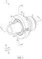
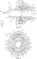
- Figure 1 is a perspective view of fluid connection assembly 10 , in a locked state.
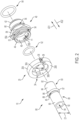
- Figure 2 is an exploded perspective view of fluid connection assembly 10 .
- Fluid connection assembly 10 generally comprises retainer 20 , tube 80 , and connector body 40 . The following description should be read in view of Figures 1-2 .
- Tube 80 comprises end 82 , section 83 , bead or shoulder 87, section 89 , end 92 , and through-bore 94 .
- Through-bore 94 extends through tube 80 from end 82 to end 92 .
- Section 83 is arranged between end 82 and shoulder 87 and comprises radially outward facing surface 84 .
- Radially outward facing surface 84 includes a substantially constant diameter.
- radially outward facing surface 84 comprises a frusto-conical taper or curvilinear surface proximate end 82 (see Figure 4 ).
- Shoulder 87 is arranged between section 83 and section 89 and comprises surface 86 and surface 88 .
- surface 86 is an axial surface facing at least partially in axial direction AD1 and surface 88 is an axial surface facing at least partially in axial direction AD2 .
- surface 86 is a frusto-conical surface extending from the radially outward facing surface of shoulder 87 radially inward in axial direction AD1 .
- surface 86 may be a linear conical shape and increases in diameter in axial direction AD2 .
- surface 86 may comprise linear portion and a conical or frusto-conical portion.
- Section 89 is arranged between shoulder 87 and end 92 and comprises radially outward facing surface 90. Radially outward facing surface 90 includes a substantially constant diameter.
- Tube 80 (or section 89 ) further comprises radially inward extending groove 85 .
- groove 85 is arranged in radially outward facing surface 90 immediately adjacent to shoulder 87 .
- groove 85 is spaced apart from shoulder 87 , for example in axial direction AD2 .
- Groove 85 is operatively arranged to engage tabs 30A-B such that retainer 20 may only lock when properly aligned with tube 80 , as will be described in greater detail below.
- Tube 80 is arranged to be inserted, specifically with end 82 first, into connector body 40 .
- Tube 80 is inserted into connector body 40 until section 83 , or radially outward facing surface 84 , engages seal 62 (see Figure 4 ). Shoulder 87 is engaged with or arranged proximate to or abuts against surface 47 of connector body 40 and groove 85 is axially aligned with apertures 55A-B , at which point retainer 20 is assembled to secure tube 80 to connector body 40 .
- Tube 80 specifically radially outward facing surface 90 , comprises diameter D1 .
- Radially inward facing surfaces 32A-B of tabs 30A-B respectively, form diameter D2 , which is less than diameter D1 .
- tube 80 may be any traditional tube or tube end form comprising a bead, radially outward extending protrusion or flange, or ramp profile, which extends radially outward and axially on the outer surface of the tube, to secure the tube within the connector body.
- tube 80 comprises a metal.
- tube 80 comprises a polymer.
- tube 80 comprises a ceramic.
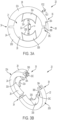
- Figure 3A is an elevational view of retainer 20 .
- Figure 3B is a front perspective view of retainer 20 , in an unlocked state.
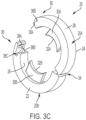
- Figure 3C is a rear perspective view of retainer 20 , in the unlocked state.
- Figure 4 is a cross-sectional view of fluid connection assembly 10 taken generally along line 4-4 in Figure 1 .
- Figure 5 is a cross-sectional view of fluid connection assembly 10 taken generally along line 5-5 in Figure 1 . The following description should be read in view of Figures 1-5 .
- Retainer 20 generally comprises section 20A , section 20B , end 22 , end 24 , radially inward facing surface 26 , and radially outward facing surface 28 .
- section 20A is hingedly connected to section 20B , via, for example, hinge 34 .
- section 20A is removably connected to section 20B .
- Radially inward facing surface 26 is operatively arranged to engage or abut against radially outward facing surface 52 of connector body 40 .
- Retainer 20 further comprises one or more tabs (e.g., tab 32A and tab 32B ) extending radially inward in radial direction RD2 from radially inward facing surface 26 .
- tabs e.g., tab 32A and tab 32B
- radially inward facing surface 26 engages or abuts against or is arranged proximate to radially outward facing surface 52
- end 22 engages or abuts against or is arranged proximate to head 58 .
- tab 30A extends through aperture 55A and engages radially outward facing surface 90 and shoulder 87 , specifically surface 88
- tab 30B extends through aperture 55B and engages radially outward facing surface 90 and shoulder 87 , specifically surface 88 , to lock tube 80 within connector body 40 .
- tab 30A and tab 30B engage groove 85 in order to form the locked state.
- retainer 20 is incapable of locking unless tabs 30A-B engage groove 85 .
- Tab 30A comprises radially inward facing surface 32A , which comprises a curvilinear surface that is substantially equal to the curvilinear surface of groove 85 (i.e., radially inward facing surface 32A and groove 85 have substantially the same diameter).
- Tab 30B comprises radially inward facing surface 32B which comprises a curvilinear surface that is substantially equal to the curvilinear surface of groove 85 (i.e., radially inward facing surface 32B and groove 85 have substantially the same diameter).
- each of radially inward facing surfaces 32A and 32B comprise diameter D2 , which is less than diameter D1 of radially outward facing surface 90 .
- tabs 30A-B are aligned with radially outward facing surface 90 , since diameter D1 is greater than diameter D2 , male connector 36 will not be capable of engaging with female connector 38 .
- Tab 30A is arranged at angle ⁇ relative to tab 30B .
- angle ⁇ is greater than 90° and less than 180°.
- angle ⁇ is greater than or equal to 180°.
- angle ⁇ is less than or equal to 90°. It should be appreciated that tabs 30A and 30B are solid components including a substantial width that circumscribes tube 80 in the locked state.
- tabs 30A and 30B prevent ingress of foreign material into fluid connection assembly 10 that may jeopardize the seal between tube 80 and connector body 40 (i.e., O-ring 62 ).
- section 20A and/or section 20B comprise width W1 and tab 30A and/or tab 30B comprise width W2 .
- Width W2 is less than width W1 .
- retainer 20 comprises a polymer.
- retainer 20 comprises a metal.
- retainer 20 comprises a ceramic.
- Section 20A comprises male connector 36 and section 20B comprises female connector 38 .
- male connector 36 on section 20A is arranged to engage female connector 38 on section 20B such that sections 20A and 20B are fixedly secured.
- male connector 36 is hook-shaped (in a radially outward direction) and includes groove 36A and projection 36B .
- Groove 36A is arranged in radially outward facing surface 28 .
- Projection 36B extends generally radially outward in radial direction RD1 from groove 36A .
- projection 36B comprises a tapered section near its top end operatively arranged to allow engagement of projection 36B with female connector 38 , specifically, aperture 38A , to occur with greater ease.
- Projection 36B further comprises channel 36C .
- Channel 36C comprises a bottom portion, and two tapered side wall portions extending from the bottom portion.
- Channel 36C is arranged to engage projection 38B of female connector 38 in order to properly align projection 36B with aperture 38A .
- Female connector 38 comprises aperture 38A extending radially inward from radially outward facing surface 28 .
- Aperture 38A is operatively arranged to engage projection 36B to lock section 20B to section 20A .
- Female connector 38 further comprises projection 38B .
- projection 38B is arranged proximate to radially inward facing surface 26 and includes at least two tapered surfaces. The tapered surfaces of projection 38B are arranged to engage channel 36C to accurately align projection 36B with aperture 38A .
- female connector 38 further comprises radial gap 38C arranged radially between aperture 38A and projection 38B . Radial gap 38C is operatively arranged to allow radial displacement of female connector 38 .
- female connector 38 engages projection 36B and displaces radially outward in radial direction RD1 .
- aperture 38A is aligned with projection 36B
- female connector 38 snaps back radially inward, in radial direction RD2 , thereby securing section 20B to section 20A .
- Gap 38C allows for this increased radial flexion of female connector 38 .
- Connector body 40 comprises through-bore 41 extending from end 42 to end 44 , radially inward facing surface 46 , radially inward facing surface 48 , groove 50 , radially outward facing surface 52 , groove 54 , head 58 , and radially outward facing surface 60 .
- Connector body 40 is arranged to be connected to a component that is filled with a fluid or through which fluid flows.
- connector body 40 may be connected to a refrigeration compressor or a transmission via radially outward facing surface 60 , which may comprise external threading.
- Connector body 40 may be screwed into a threaded hole in the compressor via head 58 (e.g., using a wrench), which is then filled with refrigerant fluid.
- head 58 is hexagonal; however, it should be appreciated that head 58 may comprise any geometry suitable for applying torque to connector body 40 .
- Another component in which fluid connector 10 , specifically connector body 40 , may be installed in is a condenser, evaporator, or pump. It should be appreciated that fluid connector 10 may be used in various other components, assemblies, and subassemblies in which fluid connection is desired.
- Radially outward facing surface 60 may further comprise groove 56 . Seal or O-ring 64 is arranged in groove 56 to create a fluid tight seal between connector body 40 and the component it is connected to. Seal 62 is arranged in connector body 40 .
- seal 62 is arranged in groove 50 to engage tube 80 (i.e., radially outward facing surface 84 ).
- Groove 50 is arranged in radially inward facing surface 48 .
- seal 62 is an O-ring.
- radially inward facing surface 46 is a substantially cylindrical surface.
- radially inward facing surface 46 comprises a frusto-conical surface or radially outward extending taper proximate end 44 .
- radially inward facing surface 48 is a substantially cylindrical surface.
- Surface 47 connects surface 46 and surface 48 .
- surface 47 is an axially facing surface.
- surface 47 is a frusto-conical surface. Surface 47 is operatively arranged to engage shoulder 87 , specifically, to prevent axial displacement of tube 80 is axial direction AD1 .
- Groove 54 is arranged in radially outward facing surface 52 . Groove 54 is arranged axially between end 44 and head 58 . In some embodiments, groove 54 is arranged axially between and spaced apart from end 44 and head 58 .
- Connector body 40 further comprises one or more apertures (e.g., apertures 55A and 55B ) arranged in radially outward facing surface 52 . Specifically, apertures 55A and 55B are arranged in groove 54 and extend from radially outward facing surface 52 to through-bore 41 .
- connector body 40 comprises a metal. In some embodiments, connector body 40 comprises a polymer. In some embodiments, connector body 40 comprises a ceramic.
- tube 80 is inserted in axial direction AD1 , with end 82 first, into connector body 40 .
- Radially outward facing surface 84 engages seal 62
- section 83 is arranged inside of connector body 40 proximate radially inward facing surface 48
- shoulder 87 is arranged inside of connector body 40 proximate surface 47 and/or radially inward facing surface 46
- section 89 is arranged at least partially inside of connector body 40 proximate radially inward facing surface 46
- groove 85 is axially aligned with apertures 55A-B . Then, retainer 20 is secured over connector body 40 .
- sections 20A and 20B are arranged over connector body 40 such that tabs 30A and 30B are aligned with groove 54 , and more specifically, apertures 55A and 55B , respectively.
- Sections 20A and 20B are displaced radially inward toward each other (i.e., in radial direction RD2 ) until female connector 38 fully engages male connector 36 and retainer 20 is in the locked position.
- engagement of female connector 38 with male connector 36 can only occur if tabs 30A-B engage groove 85 .
- Engagement of female connector 38 with male connector 36 cannot occur if tabs 30A-B engage radially outward facing surface 90 .
- radially inward facing surface 26 engages radially outward facing surface 52
- tab 30A extends through aperture 55A and radially inward facing surface 32A engages groove 85 and surface 88
- tab 30B extends through aperture 55B and radially inward facing surface 32B engages groove 85 and surface 88
- end 22 engages head 58 .
- the engagement of retainer 20 with connector body 40 and tube 80 prevents axial displacement of tube 80 in axial directions AD1 and AD2 , as well as radial directions RD1 and RD2 , relative to connector body 40 .
- female connector 38 is displaced radially outward in radial direction RD1 with respect to male connector 36 until aperture 38A disengages projection 36B.
- Sections 20A and 20B are then separated to disengage tabs 30A and 30B from shoulder 87 , at which point tube 80 can be removed from connector body 40.
Landscapes
- Engineering & Computer Science (AREA)
- General Engineering & Computer Science (AREA)
- Mechanical Engineering (AREA)
- Quick-Acting Or Multi-Walled Pipe Joints (AREA)
- Joints With Sleeves (AREA)
Claims (15)
- Fluidverbindungsanordnung (10), umfassend:einen Verbinderkörper (40), enthaltend:ein erstes Ende (42);ein zweites Ende (44);eine erste Durchgangsbohrung (41); undeine erste radial nach außen weisende Fläche (52), die mindestens eine Öffnung (55A, 55B) enthält, die sich von der ersten radial nach außen weisenden Fläche (52) zu der ersten Durchgangsbohrung (41) erstreckt; undeinen Halter (20), der funktionell so angeordnet ist, dass er abnehmbar mit dem Verbinderkörper (40) verbunden ist, wobei der Halter (20) folgendes enthält:einen ersten Abschnitt (20A);einen zweiten Abschnitt (20B), der mit dem ersten Abschnitt (20A) verbunden ist;eine erste radial nach innen weisende Fläche (26); undmindestens eine Lasche (30A, 30B), die sich von der ersten radial nach innen weisenden Fläche (26) aus erstreckt, wobei die mindestens eine Lasche (30A, 30B) eine zweite radial nach innen weisende Fläche (32A, 32B) aufweist;wobei sich in einem verriegelten Zustand die mindestens eine Lasche (30A, 30B) durch die mindestens eine Öffnung (55A, 55B) erstreckt und die erste radial nach innen weisende Fläche (26) nahe der ersten radial nach außen weisenden Fläche (52) angeordnet ist,wobeiim verriegelten Zustand der zweite Abschnitt (20B) fest am ersten Abschnitt (20A) gehalten ist,dadurch gekennzeichnet, dass der zweite Abschnitt (20B) mit dem ersten Abschnitt (20A) gelenkig verbunden ist.
- Fluidverbindungsanordnung (10) nach Anspruch 1, wobei:die mindestens eine Öffnung (55A, 55B) eine erste Öffnung (55A) und eine zweite Öffnung (55B) umfasst;die mindestens eine Lasche (30A, 30B) eine erste Lasche (30A) und eine zweite Lasche (30B) umfasst; undim verriegelten Zustand die erste Lasche (30A) sich durch die erste Öffnung (55A) und die zweite Lasche (30B) sich durch die zweite Öffnung (55B) erstreckt.
- Fluidverbindungsanordnung (10) nach Anspruch 2, wobei im verriegelten Zustand die erste Lasche (30A) in einem Winkel (α) relativ zur zweiten Lasche (30B) angeordnet ist, wobei der Winkel (α) größer als 90° und kleiner als 180° ist.
- Fluidverbindungsanordnung (10) nach Anspruch 1, wobei der erste Abschnitt (20A) einen männlichen Verbinder (36) mit einem sich radial nach außen erstreckenden Vorsprung (36B) umfasst.
- Fluidverbindungsanordnung (10) nach Anspruch 4, wobei der zweite Abschnitt (20B) einen weiblichen Verbinder (38) mit einer Öffnung (38A) umfasst, wobei die Öffnung (38A) funktionell so angeordnet ist, dass sie an den sich radial nach außen erstreckenden Vorsprung (36B) angreift, um den zweiten Abschnitt (20B) fest an dem ersten Abschnitt (20A) zu halten.
- Fluidverbindungsanordnung (10) nach Anspruch 5, wobei:der männliche Verbinder (36) außerdem einen Kanal (36C) umfasst;der weibliche Verbinder (38) außerdem einen Vorsprung (38B) aufweist; undder Vorsprung (38B) funktionell so angeordnet ist, dass er an dem Kanal (36C) anngreift, um die Öffnung (38A) mit dem sich radial nach außen erstreckenden Vorsprung (36B) auszurichten.
- Fluidverbindungsanordnung (10) nach Anspruch 1, wobei die zweit radial nach innen weisende Fläche (32A, 32B) gekrümmt ist.
- Fluidverbindungsanordnung (10) nach Anspruch 1, die ferner einen Tubus (80) mit einer Schulter (87) umfasst, wobei der Halter (20) so angeordnet ist, dass er den Tubus (80) an dem Verbinderkörper (40) hält.
- Fluidverbindungsanordnung (10) nach Anspruch 8, wobei die mindestens eine Lasche (30A, 30B) funktionsmäßig so angeordnet ist, dass sie an der Schulter (87) in Angriff kommt.
- Fluidverbindungsanordnung (10) nach Anspruch 8, wobei:der Tubus (80) außerdem eine sich radial nach innen erstreckende Nut (85) aufweist, die nahe der Schulter (87) angeordnet ist; undim verriegelten Zustand die mindestens eine Lasche (30A, 30B) an der Nut (85) in Angriff kommt.
- Fluidverbindungsanordnung (10) nach Anspruch 1, wobei der erste Abschnitt (20A) eine erste Breite (W1) und die mindestens eine Lasche (30A, 30B) eine zweite Breite (W2) aufweist, wobei die zweite Breite (W2) geringer als die erste Breite (W1) ist.
- Fluidverbindungsanordnung (10) nach Anspruch 6, wobei der weibliche Verbinder (38) ferner einen radialen Spalt (38C) aufweist, der radial zwischen der Öffnung (38A) und dem Vorsprung (38B) angeordnet ist.
- Fluidverbindungsanordnung (10) nach Anspruch 4, wobei:der Halter (20) ferner eine zweite radial nach außen weisende Fläche (28) aufweist;der männliche Verbinder (36) ferner eine Nut (36A) aufweist, die in der zweiten radial nach außen weisenden Fläche (28) angeordnet ist; undder sich radial nach außen erstreckende Vorsprung (36B) in der Nut (36A) angeordnet ist.
- Fluidverbindungsanordnung (10) nach Anspruch 8, wobei:der Tubus (80) eine zweite radial nach außen weisende Fläche (90) mit einem ersten Durchmesser (D1) aufweist; undim verriegelten Zustand die zweite radial nach innen weisende Fläche (32A, 32B) einen zweiten Durchmesser (D2) aufweist, der geringer als der erste Durchmesser (D1) ist.
- Fluidverbindungsanordnung (10) nach Anspruch 10, wobei die Halterung (20) nicht in der Lage ist, den verriegelten Zustand zu bilden, wenn die mindestens eine Lasche (30A, 30B) nicht axial mit der Nut (85) ausgerichtet ist.
Applications Claiming Priority (1)
| Application Number | Priority Date | Filing Date | Title |
|---|---|---|---|
| PCT/US2020/057315 WO2022093167A1 (en) | 2020-10-26 | 2020-10-26 | Fluid connection assembly |
Publications (2)
| Publication Number | Publication Date |
|---|---|
| EP4232740A1 EP4232740A1 (de) | 2023-08-30 |
| EP4232740B1 true EP4232740B1 (de) | 2024-12-11 |
Family
ID=73695114
Family Applications (1)
| Application Number | Title | Priority Date | Filing Date |
|---|---|---|---|
| EP20817534.9A Active EP4232740B1 (de) | 2020-10-26 | 2020-10-26 | Fluidverbindungsanordnung |
Country Status (5)
| Country | Link |
|---|---|
| US (1) | US12111000B2 (de) |
| EP (1) | EP4232740B1 (de) |
| JP (1) | JP2023547911A (de) |
| KR (1) | KR102798623B1 (de) |
| WO (1) | WO2022093167A1 (de) |
Families Citing this family (6)
| Publication number | Priority date | Publication date | Assignee | Title |
|---|---|---|---|---|
| JP7506513B2 (ja) * | 2020-04-09 | 2024-06-26 | 株式会社東郷製作所 | コネクタ |
| US12104021B2 (en) | 2021-02-22 | 2024-10-01 | The Procter & Gamble Company | Recycling of superabsorbent fibers with an extensional flow device |
| US12152112B2 (en) | 2021-02-22 | 2024-11-26 | The Procter & Gamble Company | Degradation of superabsorbent fibers via oxidative degradation |
| US12384900B2 (en) | 2021-02-22 | 2025-08-12 | The Procter & Gamble Company | Recycling of superabsorbent fibers via UV irradiation in flow system |
| CN116917392A (zh) * | 2021-02-22 | 2023-10-20 | 宝洁公司 | 利用拉伸流动装置回收超吸收纤维 |
| US12412791B2 (en) * | 2023-01-09 | 2025-09-09 | Dell Products L.P. | Liquid-tight structure with a fastener component |
Citations (1)
| Publication number | Priority date | Publication date | Assignee | Title |
|---|---|---|---|---|
| US20190353286A1 (en) * | 2014-05-30 | 2019-11-21 | Oetiker Ny, Inc. | Fluid connector with full insertion assurance cap with secondary latches |
Family Cites Families (50)
| Publication number | Priority date | Publication date | Assignee | Title |
|---|---|---|---|---|
| JPS5322061Y2 (de) | 1971-02-04 | 1978-06-08 | ||
| JPS5820136Y2 (ja) | 1980-08-26 | 1983-04-26 | 奥 俊三 | まきえ容器 |
| US4640534A (en) | 1986-03-14 | 1987-02-03 | John T. Hoskins | Fluid coupling assembly |
| US4753458A (en) | 1986-08-28 | 1988-06-28 | Harvard Industries, Inc. | Quick connector assembly |
| JP2691550B2 (ja) * | 1988-03-01 | 1997-12-17 | 臼井国際産業株式会社 | 細径配管接続用コネクター |
| JPH04224394A (ja) * | 1990-12-22 | 1992-08-13 | Usui Internatl Ind Co Ltd | 配管用コネクタ |
| US5297818A (en) | 1991-12-18 | 1994-03-29 | Itt Corporation | Retainer for pop-top indicator |
| US5459500A (en) | 1992-03-25 | 1995-10-17 | Scitex Digital Printing, Inc. | Charge plate connectors and method of making |
| DE19512432B4 (de) | 1994-04-04 | 2007-04-26 | Denso Corp., Kariya | Vorrichtung zum Verbinden von Rohrleitungen mittels zweier Halbschalen |
| US5472242A (en) | 1994-06-24 | 1995-12-05 | Petersen; Horst U. | End-fitting for pipe connection having proper insertion indicator |
| US5468028A (en) | 1994-12-19 | 1995-11-21 | Dana Corporation | Quick connect tube couplings |
| JP3113170B2 (ja) * | 1994-12-28 | 2000-11-27 | 株式会社東郷製作所 | コネクタ |
| GB9620011D0 (en) | 1996-09-25 | 1996-11-13 | Bend All Mfg Inc | Snap-in end fitting for pipes |
| AU759638B2 (en) | 1997-11-18 | 2003-04-17 | Oystertec Plc | Joint |
| US5909901A (en) | 1998-02-22 | 1999-06-08 | Jiffy-Tite Company, Inc. | Disconnect tool for a fluid line quick-connect assembly |
| JP4703885B2 (ja) | 2001-04-13 | 2011-06-15 | 株式会社東郷製作所 | コネクタ |
| US6913294B2 (en) | 2002-11-14 | 2005-07-05 | Halla Climate Control Canada, Inc. | Coupling for coaxial connection of fluid conduits |
| US6880859B2 (en) | 2003-07-31 | 2005-04-19 | Stanley Aviation Corporation | Conduit coupling assembly |
| US7240930B2 (en) | 2004-02-23 | 2007-07-10 | Stravitz David M | Quick-connect/quick-disconnect conduit connectors |
| JP2006038142A (ja) | 2004-07-28 | 2006-02-09 | Denso Corp | 配管接続用クランプ |
| US7963570B2 (en) | 2005-09-01 | 2011-06-21 | The Gates Corporation | Quick connect coupling stabilization apparatus, systems and methods |
| KR100894664B1 (ko) | 2004-10-29 | 2009-04-24 | 더 게이츠 코포레이션 | 신속 연결 커플링 |
| US7128347B2 (en) | 2004-11-18 | 2006-10-31 | Ti Group Automotive Systems, Llc | Passive transmitter for a quick connector |
| ITTO20050035U1 (it) | 2005-03-15 | 2006-09-16 | Ferrero Rubinetterie S R L | Collettore per fluidi |
| ES2349016T3 (es) * | 2005-05-03 | 2010-12-21 | Ti Group Automotive Systems, L.L.C. | Conectador rapido. |
| US7497477B2 (en) | 2005-06-15 | 2009-03-03 | Ti Group Automotive Systems, Llc | Pull tab verifier assembly for quick connectors |
| ES2348392T3 (es) | 2006-01-05 | 2010-12-03 | Norma Germany Gmbh | Sistema de conexion con racor tubular para unir piezas de paso de fluidos. |
| US8328457B2 (en) | 2007-07-20 | 2012-12-11 | Twin Bay Medical, Inc. | Sanitary clamp |
| FR2919372B1 (fr) | 2007-07-25 | 2013-05-10 | Legris Sa | Raccord a temoin. |
| JP5266956B2 (ja) | 2007-09-11 | 2013-08-21 | ダイキン工業株式会社 | 両用管継手、この両用管継手用の専用工具、冷凍装置、分離型空気調和機 |
| IT1390600B1 (it) | 2008-07-08 | 2011-09-09 | Sit La Precisa Spa Con Socio Unico | Sistema di connessione a tenuta di gruppi valvolari con rispettive tubazioni, in particolare nell'impiego con gas combustibili |
| EP3412333A1 (de) | 2011-03-07 | 2018-12-12 | Nordson Corporation | Klemme für sanitärarmatur |
| JP5743765B2 (ja) | 2011-07-11 | 2015-07-01 | ジョプラックス株式会社 | 管継手 |
| JP5729373B2 (ja) | 2012-12-28 | 2015-06-03 | ダイキン工業株式会社 | 弁 |
| JP5707010B2 (ja) * | 2013-02-28 | 2015-04-22 | 未来工業株式会社 | 管接続具及び管接続装置 |
| ES2782848T3 (es) | 2013-11-27 | 2020-09-16 | Oetiker Ny Inc | Acoplamiento de fluido con conexión de bloqueo |
| PL3149381T3 (pl) | 2014-05-30 | 2019-04-30 | Oetiker Ny Inc | Złącze dla płynu z nasadką zabezpieczającą całkowite wstawienie z pomocniczymi zatrzaskami |
| US20170114935A1 (en) | 2014-05-30 | 2017-04-27 | Jiffy-Tite Co., Inc. | Fluid connector with full insertion assurance cap disconnect tool |
| JP6488476B2 (ja) * | 2014-09-30 | 2019-03-27 | 丸一株式会社 | 管体の接続構造 |
| US9909702B2 (en) | 2015-06-10 | 2018-03-06 | Ford Global Technologies, Llc | Quick connect system for automotive fluid transport lines |
| US10823323B2 (en) | 2016-03-03 | 2020-11-03 | Oetiker Ny, Inc. | Fluid connector having a deformable tab and plug/connector assembly |
| GB2548559A (en) | 2016-03-17 | 2017-09-27 | Eaton Ltd | Aircraft fluid line coupling assembly for releasably interconnecting fluid conveying members |
| US10281075B2 (en) | 2016-11-15 | 2019-05-07 | Campbell Fittings, Inc. | Quick disconnect coupling for conduit |
| EP3361134B1 (de) | 2017-02-09 | 2020-04-29 | Georg Fischer JRG AG | Verbindungseinheit |
| US10816121B2 (en) | 2017-05-09 | 2020-10-27 | Martinrea International US Inc. | Quick connect coupling with verifier |
| ES2920966T3 (es) | 2017-06-29 | 2022-08-12 | Cadillac Rubber & Plastics Inc | Conector rápido |
| DE102017220448A1 (de) * | 2017-11-16 | 2019-05-16 | Mahle International Gmbh | Fluidleitungskupplung mit Sicherungsklammer |
| JP7384579B2 (ja) | 2019-06-20 | 2023-11-21 | 株式会社水道技術開発機構 | 管接続部の離脱防止構造 |
| CN212251624U (zh) | 2020-03-04 | 2020-12-29 | 泰州长力树脂管有限公司 | 即插式三通快插接头体 |
| CN111594624B (zh) | 2020-05-31 | 2021-11-23 | 特技阀门集团有限公司 | 一种快接式的蝶阀 |
-
2020
- 2020-10-26 JP JP2023525578A patent/JP2023547911A/ja not_active Ceased
- 2020-10-26 EP EP20817534.9A patent/EP4232740B1/de active Active
- 2020-10-26 US US18/246,881 patent/US12111000B2/en active Active
- 2020-10-26 WO PCT/US2020/057315 patent/WO2022093167A1/en not_active Ceased
- 2020-10-26 KR KR1020237017410A patent/KR102798623B1/ko active Active
Patent Citations (1)
| Publication number | Priority date | Publication date | Assignee | Title |
|---|---|---|---|---|
| US20190353286A1 (en) * | 2014-05-30 | 2019-11-21 | Oetiker Ny, Inc. | Fluid connector with full insertion assurance cap with secondary latches |
Also Published As
| Publication number | Publication date |
|---|---|
| KR20230093460A (ko) | 2023-06-27 |
| US20230366498A1 (en) | 2023-11-16 |
| WO2022093167A1 (en) | 2022-05-05 |
| US12111000B2 (en) | 2024-10-08 |
| JP2023547911A (ja) | 2023-11-14 |
| EP4232740A1 (de) | 2023-08-30 |
| KR102798623B1 (ko) | 2025-04-23 |
Similar Documents
| Publication | Publication Date | Title |
|---|---|---|
| EP4232740B1 (de) | Fluidverbindungsanordnung | |
| US12152714B2 (en) | Fluid connection assembly | |
| US20250237337A1 (en) | Fluid connection assembly | |
| WO2022256757A1 (en) | Fluid connection assembly | |
| EP4232739B1 (de) | Fluidverbindungsanordnung | |
| US12188584B2 (en) | Fluid connection assembly | |
| US20240191820A1 (en) | Fluid connection assembly and fluid connection assembly connect and disconnect tools | |
| KR20230122167A (ko) | 시각적 연결 확인부를 갖는 변조 방지 유체 연결 조립체 | |
| WO2023101701A1 (en) | Fluid connection assembly with a retainer holder | |
| US12222057B2 (en) | Fluid connection assembly | |
| KR102899508B1 (ko) | 유체 연결 조립체 | |
| WO2022245346A1 (en) | Disconnect tool for a fluid connection assembly | |
| WO2022265676A1 (en) | Fluid connection assembly |
Legal Events
| Date | Code | Title | Description |
|---|---|---|---|
| STAA | Information on the status of an ep patent application or granted ep patent |
Free format text: STATUS: UNKNOWN |
|
| STAA | Information on the status of an ep patent application or granted ep patent |
Free format text: STATUS: THE INTERNATIONAL PUBLICATION HAS BEEN MADE |
|
| PUAI | Public reference made under article 153(3) epc to a published international application that has entered the european phase |
Free format text: ORIGINAL CODE: 0009012 |
|
| STAA | Information on the status of an ep patent application or granted ep patent |
Free format text: STATUS: REQUEST FOR EXAMINATION WAS MADE |
|
| 17P | Request for examination filed |
Effective date: 20230329 |
|
| AK | Designated contracting states |
Kind code of ref document: A1 Designated state(s): AL AT BE BG CH CY CZ DE DK EE ES FI FR GB GR HR HU IE IS IT LI LT LU LV MC MK MT NL NO PL PT RO RS SE SI SK SM TR |
|
| DAV | Request for validation of the european patent (deleted) | ||
| DAX | Request for extension of the european patent (deleted) | ||
| GRAP | Despatch of communication of intention to grant a patent |
Free format text: ORIGINAL CODE: EPIDOSNIGR1 |
|
| STAA | Information on the status of an ep patent application or granted ep patent |
Free format text: STATUS: GRANT OF PATENT IS INTENDED |
|
| INTG | Intention to grant announced |
Effective date: 20240619 |
|
| GRAS | Grant fee paid |
Free format text: ORIGINAL CODE: EPIDOSNIGR3 |
|
| GRAA | (expected) grant |
Free format text: ORIGINAL CODE: 0009210 |
|
| STAA | Information on the status of an ep patent application or granted ep patent |
Free format text: STATUS: THE PATENT HAS BEEN GRANTED |
|
| AK | Designated contracting states |
Kind code of ref document: B1 Designated state(s): AL AT BE BG CH CY CZ DE DK EE ES FI FR GB GR HR HU IE IS IT LI LT LU LV MC MK MT NL NO PL PT RO RS SE SI SK SM TR |
|
| REG | Reference to a national code |
Ref country code: GB Ref legal event code: FG4D |
|
| REG | Reference to a national code |
Ref country code: CH Ref legal event code: EP |
|
| REG | Reference to a national code |
Ref country code: DE Ref legal event code: R096 Ref document number: 602020043066 Country of ref document: DE |
|
| REG | Reference to a national code |
Ref country code: IE Ref legal event code: FG4D |
|
| REG | Reference to a national code |
Ref country code: LT Ref legal event code: MG9D |
|
| PG25 | Lapsed in a contracting state [announced via postgrant information from national office to epo] |
Ref country code: HR Free format text: LAPSE BECAUSE OF FAILURE TO SUBMIT A TRANSLATION OF THE DESCRIPTION OR TO PAY THE FEE WITHIN THE PRESCRIBED TIME-LIMIT Effective date: 20241211 |
|
| PG25 | Lapsed in a contracting state [announced via postgrant information from national office to epo] |
Ref country code: FI Free format text: LAPSE BECAUSE OF FAILURE TO SUBMIT A TRANSLATION OF THE DESCRIPTION OR TO PAY THE FEE WITHIN THE PRESCRIBED TIME-LIMIT Effective date: 20241211 |
|
| PG25 | Lapsed in a contracting state [announced via postgrant information from national office to epo] |
Ref country code: BG Free format text: LAPSE BECAUSE OF FAILURE TO SUBMIT A TRANSLATION OF THE DESCRIPTION OR TO PAY THE FEE WITHIN THE PRESCRIBED TIME-LIMIT Effective date: 20241211 |
|
| REG | Reference to a national code |
Ref country code: NL Ref legal event code: MP Effective date: 20241211 |
|
| PG25 | Lapsed in a contracting state [announced via postgrant information from national office to epo] |
Ref country code: ES Free format text: LAPSE BECAUSE OF FAILURE TO SUBMIT A TRANSLATION OF THE DESCRIPTION OR TO PAY THE FEE WITHIN THE PRESCRIBED TIME-LIMIT Effective date: 20241211 |
|
| PG25 | Lapsed in a contracting state [announced via postgrant information from national office to epo] |
Ref country code: NO Free format text: LAPSE BECAUSE OF FAILURE TO SUBMIT A TRANSLATION OF THE DESCRIPTION OR TO PAY THE FEE WITHIN THE PRESCRIBED TIME-LIMIT Effective date: 20250311 |
|
| PG25 | Lapsed in a contracting state [announced via postgrant information from national office to epo] |
Ref country code: GR Free format text: LAPSE BECAUSE OF FAILURE TO SUBMIT A TRANSLATION OF THE DESCRIPTION OR TO PAY THE FEE WITHIN THE PRESCRIBED TIME-LIMIT Effective date: 20250312 Ref country code: LV Free format text: LAPSE BECAUSE OF FAILURE TO SUBMIT A TRANSLATION OF THE DESCRIPTION OR TO PAY THE FEE WITHIN THE PRESCRIBED TIME-LIMIT Effective date: 20241211 |
|
| PG25 | Lapsed in a contracting state [announced via postgrant information from national office to epo] |
Ref country code: RS Free format text: LAPSE BECAUSE OF FAILURE TO SUBMIT A TRANSLATION OF THE DESCRIPTION OR TO PAY THE FEE WITHIN THE PRESCRIBED TIME-LIMIT Effective date: 20250311 |
|
| PG25 | Lapsed in a contracting state [announced via postgrant information from national office to epo] |
Ref country code: NL Free format text: LAPSE BECAUSE OF FAILURE TO SUBMIT A TRANSLATION OF THE DESCRIPTION OR TO PAY THE FEE WITHIN THE PRESCRIBED TIME-LIMIT Effective date: 20241211 |
|
| REG | Reference to a national code |
Ref country code: AT Ref legal event code: MK05 Ref document number: 1750609 Country of ref document: AT Kind code of ref document: T Effective date: 20241211 |
|
| PG25 | Lapsed in a contracting state [announced via postgrant information from national office to epo] |
Ref country code: SM Free format text: LAPSE BECAUSE OF FAILURE TO SUBMIT A TRANSLATION OF THE DESCRIPTION OR TO PAY THE FEE WITHIN THE PRESCRIBED TIME-LIMIT Effective date: 20241211 |
|
| PG25 | Lapsed in a contracting state [announced via postgrant information from national office to epo] |
Ref country code: PL Free format text: LAPSE BECAUSE OF FAILURE TO SUBMIT A TRANSLATION OF THE DESCRIPTION OR TO PAY THE FEE WITHIN THE PRESCRIBED TIME-LIMIT Effective date: 20241211 |
|
| PG25 | Lapsed in a contracting state [announced via postgrant information from national office to epo] |
Ref country code: IS Free format text: LAPSE BECAUSE OF FAILURE TO SUBMIT A TRANSLATION OF THE DESCRIPTION OR TO PAY THE FEE WITHIN THE PRESCRIBED TIME-LIMIT Effective date: 20250411 |
|
| PG25 | Lapsed in a contracting state [announced via postgrant information from national office to epo] |
Ref country code: PT Free format text: LAPSE BECAUSE OF FAILURE TO SUBMIT A TRANSLATION OF THE DESCRIPTION OR TO PAY THE FEE WITHIN THE PRESCRIBED TIME-LIMIT Effective date: 20250411 |
|
| PG25 | Lapsed in a contracting state [announced via postgrant information from national office to epo] |
Ref country code: EE Free format text: LAPSE BECAUSE OF FAILURE TO SUBMIT A TRANSLATION OF THE DESCRIPTION OR TO PAY THE FEE WITHIN THE PRESCRIBED TIME-LIMIT Effective date: 20241211 |
|
| PG25 | Lapsed in a contracting state [announced via postgrant information from national office to epo] |
Ref country code: RO Free format text: LAPSE BECAUSE OF FAILURE TO SUBMIT A TRANSLATION OF THE DESCRIPTION OR TO PAY THE FEE WITHIN THE PRESCRIBED TIME-LIMIT Effective date: 20241211 Ref country code: AT Free format text: LAPSE BECAUSE OF FAILURE TO SUBMIT A TRANSLATION OF THE DESCRIPTION OR TO PAY THE FEE WITHIN THE PRESCRIBED TIME-LIMIT Effective date: 20241211 |
|
| PG25 | Lapsed in a contracting state [announced via postgrant information from national office to epo] |
Ref country code: SK Free format text: LAPSE BECAUSE OF FAILURE TO SUBMIT A TRANSLATION OF THE DESCRIPTION OR TO PAY THE FEE WITHIN THE PRESCRIBED TIME-LIMIT Effective date: 20241211 |
|
| PG25 | Lapsed in a contracting state [announced via postgrant information from national office to epo] |
Ref country code: CZ Free format text: LAPSE BECAUSE OF FAILURE TO SUBMIT A TRANSLATION OF THE DESCRIPTION OR TO PAY THE FEE WITHIN THE PRESCRIBED TIME-LIMIT Effective date: 20241211 |
|
| PG25 | Lapsed in a contracting state [announced via postgrant information from national office to epo] |
Ref country code: SE Free format text: LAPSE BECAUSE OF FAILURE TO SUBMIT A TRANSLATION OF THE DESCRIPTION OR TO PAY THE FEE WITHIN THE PRESCRIBED TIME-LIMIT Effective date: 20241211 |
|
| REG | Reference to a national code |
Ref country code: DE Ref legal event code: R097 Ref document number: 602020043066 Country of ref document: DE |
|
| PG25 | Lapsed in a contracting state [announced via postgrant information from national office to epo] |
Ref country code: DK Free format text: LAPSE BECAUSE OF FAILURE TO SUBMIT A TRANSLATION OF THE DESCRIPTION OR TO PAY THE FEE WITHIN THE PRESCRIBED TIME-LIMIT Effective date: 20241211 |
|
| PLBE | No opposition filed within time limit |
Free format text: ORIGINAL CODE: 0009261 |
|
| STAA | Information on the status of an ep patent application or granted ep patent |
Free format text: STATUS: NO OPPOSITION FILED WITHIN TIME LIMIT |
|
| 26N | No opposition filed |
Effective date: 20250912 |