EP4232525B1 - Verfahren zur vergasung von organischem material und anlage zur durchführung des verfahrens - Google Patents
Verfahren zur vergasung von organischem material und anlage zur durchführung des verfahrens Download PDFInfo
- Publication number
- EP4232525B1 EP4232525B1 EP21815279.1A EP21815279A EP4232525B1 EP 4232525 B1 EP4232525 B1 EP 4232525B1 EP 21815279 A EP21815279 A EP 21815279A EP 4232525 B1 EP4232525 B1 EP 4232525B1
- Authority
- EP
- European Patent Office
- Prior art keywords
- reactor
- pyrolysis gas
- pyrolysis
- organic material
- gas
- Prior art date
- Legal status (The legal status is an assumption and is not a legal conclusion. Google has not performed a legal analysis and makes no representation as to the accuracy of the status listed.)
- Active
Links
Images

Classifications
-
- C—CHEMISTRY; METALLURGY
- C10—PETROLEUM, GAS OR COKE INDUSTRIES; TECHNICAL GASES CONTAINING CARBON MONOXIDE; FUELS; LUBRICANTS; PEAT
- C10B—DESTRUCTIVE DISTILLATION OF CARBONACEOUS MATERIALS FOR PRODUCTION OF GAS, COKE, TAR, OR SIMILAR MATERIALS
- C10B53/00—Destructive distillation, specially adapted for particular solid raw materials or solid raw materials in special form
- C10B53/02—Destructive distillation, specially adapted for particular solid raw materials or solid raw materials in special form of cellulose-containing material
-
- C—CHEMISTRY; METALLURGY
- C10—PETROLEUM, GAS OR COKE INDUSTRIES; TECHNICAL GASES CONTAINING CARBON MONOXIDE; FUELS; LUBRICANTS; PEAT
- C10B—DESTRUCTIVE DISTILLATION OF CARBONACEOUS MATERIALS FOR PRODUCTION OF GAS, COKE, TAR, OR SIMILAR MATERIALS
- C10B47/00—Destructive distillation of solid carbonaceous materials with indirect heating, e.g. by external combustion
- C10B47/28—Other processes
- C10B47/32—Other processes in ovens with mechanical conveying means
- C10B47/44—Other processes in ovens with mechanical conveying means with conveyor-screws
-
- C—CHEMISTRY; METALLURGY
- C10—PETROLEUM, GAS OR COKE INDUSTRIES; TECHNICAL GASES CONTAINING CARBON MONOXIDE; FUELS; LUBRICANTS; PEAT
- C10B—DESTRUCTIVE DISTILLATION OF CARBONACEOUS MATERIALS FOR PRODUCTION OF GAS, COKE, TAR, OR SIMILAR MATERIALS
- C10B57/00—Other carbonising or coking processes; Features of destructive distillation processes in general
- C10B57/08—Non-mechanical pretreatment of the charge, e.g. desulfurization
- C10B57/10—Drying
-
- C—CHEMISTRY; METALLURGY
- C10—PETROLEUM, GAS OR COKE INDUSTRIES; TECHNICAL GASES CONTAINING CARBON MONOXIDE; FUELS; LUBRICANTS; PEAT
- C10J—PRODUCTION OF PRODUCER GAS, WATER-GAS, SYNTHESIS GAS FROM SOLID CARBONACEOUS MATERIAL, OR MIXTURES CONTAINING THESE GASES; CARBURETTING AIR OR OTHER GASES
- C10J3/00—Production of combustible gases containing carbon monoxide from solid carbonaceous fuels
- C10J3/02—Fixed-bed gasification of lump fuel
- C10J3/06—Continuous processes
- C10J3/14—Continuous processes using gaseous heat-carriers
-
- C—CHEMISTRY; METALLURGY
- C10—PETROLEUM, GAS OR COKE INDUSTRIES; TECHNICAL GASES CONTAINING CARBON MONOXIDE; FUELS; LUBRICANTS; PEAT
- C10J—PRODUCTION OF PRODUCER GAS, WATER-GAS, SYNTHESIS GAS FROM SOLID CARBONACEOUS MATERIAL, OR MIXTURES CONTAINING THESE GASES; CARBURETTING AIR OR OTHER GASES
- C10J3/00—Production of combustible gases containing carbon monoxide from solid carbonaceous fuels
- C10J3/58—Production of combustible gases containing carbon monoxide from solid carbonaceous fuels combined with pre-distillation of the fuel
- C10J3/60—Processes
- C10J3/62—Processes with separate withdrawal of the distillation products
-
- C—CHEMISTRY; METALLURGY
- C10—PETROLEUM, GAS OR COKE INDUSTRIES; TECHNICAL GASES CONTAINING CARBON MONOXIDE; FUELS; LUBRICANTS; PEAT
- C10J—PRODUCTION OF PRODUCER GAS, WATER-GAS, SYNTHESIS GAS FROM SOLID CARBONACEOUS MATERIAL, OR MIXTURES CONTAINING THESE GASES; CARBURETTING AIR OR OTHER GASES
- C10J3/00—Production of combustible gases containing carbon monoxide from solid carbonaceous fuels
- C10J3/58—Production of combustible gases containing carbon monoxide from solid carbonaceous fuels combined with pre-distillation of the fuel
- C10J3/60—Processes
- C10J3/64—Processes with decomposition of the distillation products
- C10J3/66—Processes with decomposition of the distillation products by introducing them into the gasification zone
-
- C—CHEMISTRY; METALLURGY
- C10—PETROLEUM, GAS OR COKE INDUSTRIES; TECHNICAL GASES CONTAINING CARBON MONOXIDE; FUELS; LUBRICANTS; PEAT
- C10K—PURIFYING OR MODIFYING THE CHEMICAL COMPOSITION OF COMBUSTIBLE GASES CONTAINING CARBON MONOXIDE
- C10K3/00—Modifying the chemical composition of combustible gases containing carbon monoxide to produce an improved fuel, e.g. one of different calorific value, which may be free from carbon monoxide
- C10K3/001—Modifying the chemical composition of combustible gases containing carbon monoxide to produce an improved fuel, e.g. one of different calorific value, which may be free from carbon monoxide by thermal treatment
- C10K3/003—Reducing the tar content
- C10K3/005—Reducing the tar content by partial oxidation
-
- C—CHEMISTRY; METALLURGY
- C10—PETROLEUM, GAS OR COKE INDUSTRIES; TECHNICAL GASES CONTAINING CARBON MONOXIDE; FUELS; LUBRICANTS; PEAT
- C10K—PURIFYING OR MODIFYING THE CHEMICAL COMPOSITION OF COMBUSTIBLE GASES CONTAINING CARBON MONOXIDE
- C10K3/00—Modifying the chemical composition of combustible gases containing carbon monoxide to produce an improved fuel, e.g. one of different calorific value, which may be free from carbon monoxide
- C10K3/001—Modifying the chemical composition of combustible gases containing carbon monoxide to produce an improved fuel, e.g. one of different calorific value, which may be free from carbon monoxide by thermal treatment
- C10K3/003—Reducing the tar content
- C10K3/008—Reducing the tar content by cracking
-
- C—CHEMISTRY; METALLURGY
- C10—PETROLEUM, GAS OR COKE INDUSTRIES; TECHNICAL GASES CONTAINING CARBON MONOXIDE; FUELS; LUBRICANTS; PEAT
- C10J—PRODUCTION OF PRODUCER GAS, WATER-GAS, SYNTHESIS GAS FROM SOLID CARBONACEOUS MATERIAL, OR MIXTURES CONTAINING THESE GASES; CARBURETTING AIR OR OTHER GASES
- C10J2200/00—Details of gasification apparatus
- C10J2200/15—Details of feeding means
- C10J2200/152—Nozzles or lances for introducing gas, liquids or suspensions
-
- C—CHEMISTRY; METALLURGY
- C10—PETROLEUM, GAS OR COKE INDUSTRIES; TECHNICAL GASES CONTAINING CARBON MONOXIDE; FUELS; LUBRICANTS; PEAT
- C10J—PRODUCTION OF PRODUCER GAS, WATER-GAS, SYNTHESIS GAS FROM SOLID CARBONACEOUS MATERIAL, OR MIXTURES CONTAINING THESE GASES; CARBURETTING AIR OR OTHER GASES
- C10J2200/00—Details of gasification apparatus
- C10J2200/15—Details of feeding means
- C10J2200/158—Screws
-
- C—CHEMISTRY; METALLURGY
- C10—PETROLEUM, GAS OR COKE INDUSTRIES; TECHNICAL GASES CONTAINING CARBON MONOXIDE; FUELS; LUBRICANTS; PEAT
- C10J—PRODUCTION OF PRODUCER GAS, WATER-GAS, SYNTHESIS GAS FROM SOLID CARBONACEOUS MATERIAL, OR MIXTURES CONTAINING THESE GASES; CARBURETTING AIR OR OTHER GASES
- C10J2300/00—Details of gasification processes
- C10J2300/09—Details of the feed, e.g. feeding of spent catalyst, inert gas or halogens
- C10J2300/0913—Carbonaceous raw material
- C10J2300/0916—Biomass
-
- C—CHEMISTRY; METALLURGY
- C10—PETROLEUM, GAS OR COKE INDUSTRIES; TECHNICAL GASES CONTAINING CARBON MONOXIDE; FUELS; LUBRICANTS; PEAT
- C10J—PRODUCTION OF PRODUCER GAS, WATER-GAS, SYNTHESIS GAS FROM SOLID CARBONACEOUS MATERIAL, OR MIXTURES CONTAINING THESE GASES; CARBURETTING AIR OR OTHER GASES
- C10J2300/00—Details of gasification processes
- C10J2300/09—Details of the feed, e.g. feeding of spent catalyst, inert gas or halogens
- C10J2300/0953—Gasifying agents
- C10J2300/0956—Air or oxygen enriched air
-
- C—CHEMISTRY; METALLURGY
- C10—PETROLEUM, GAS OR COKE INDUSTRIES; TECHNICAL GASES CONTAINING CARBON MONOXIDE; FUELS; LUBRICANTS; PEAT
- C10J—PRODUCTION OF PRODUCER GAS, WATER-GAS, SYNTHESIS GAS FROM SOLID CARBONACEOUS MATERIAL, OR MIXTURES CONTAINING THESE GASES; CARBURETTING AIR OR OTHER GASES
- C10J2300/00—Details of gasification processes
- C10J2300/09—Details of the feed, e.g. feeding of spent catalyst, inert gas or halogens
- C10J2300/0953—Gasifying agents
- C10J2300/0973—Water
- C10J2300/0976—Water as steam
-
- C—CHEMISTRY; METALLURGY
- C10—PETROLEUM, GAS OR COKE INDUSTRIES; TECHNICAL GASES CONTAINING CARBON MONOXIDE; FUELS; LUBRICANTS; PEAT
- C10J—PRODUCTION OF PRODUCER GAS, WATER-GAS, SYNTHESIS GAS FROM SOLID CARBONACEOUS MATERIAL, OR MIXTURES CONTAINING THESE GASES; CARBURETTING AIR OR OTHER GASES
- C10J2300/00—Details of gasification processes
- C10J2300/12—Heating the gasifier
- C10J2300/1207—Heating the gasifier using pyrolysis gas as fuel
-
- C—CHEMISTRY; METALLURGY
- C10—PETROLEUM, GAS OR COKE INDUSTRIES; TECHNICAL GASES CONTAINING CARBON MONOXIDE; FUELS; LUBRICANTS; PEAT
- C10J—PRODUCTION OF PRODUCER GAS, WATER-GAS, SYNTHESIS GAS FROM SOLID CARBONACEOUS MATERIAL, OR MIXTURES CONTAINING THESE GASES; CARBURETTING AIR OR OTHER GASES
- C10J2300/00—Details of gasification processes
- C10J2300/12—Heating the gasifier
- C10J2300/1253—Heating the gasifier by injecting hot gas
-
- C—CHEMISTRY; METALLURGY
- C10—PETROLEUM, GAS OR COKE INDUSTRIES; TECHNICAL GASES CONTAINING CARBON MONOXIDE; FUELS; LUBRICANTS; PEAT
- C10J—PRODUCTION OF PRODUCER GAS, WATER-GAS, SYNTHESIS GAS FROM SOLID CARBONACEOUS MATERIAL, OR MIXTURES CONTAINING THESE GASES; CARBURETTING AIR OR OTHER GASES
- C10J2300/00—Details of gasification processes
- C10J2300/16—Integration of gasification processes with another plant or parts within the plant
- C10J2300/1603—Integration of gasification processes with another plant or parts within the plant with gas treatment
- C10J2300/1609—Post-reduction, e.g. on a red-white-hot coke or coal bed
-
- Y—GENERAL TAGGING OF NEW TECHNOLOGICAL DEVELOPMENTS; GENERAL TAGGING OF CROSS-SECTIONAL TECHNOLOGIES SPANNING OVER SEVERAL SECTIONS OF THE IPC; TECHNICAL SUBJECTS COVERED BY FORMER USPC CROSS-REFERENCE ART COLLECTIONS [XRACs] AND DIGESTS
- Y02—TECHNOLOGIES OR APPLICATIONS FOR MITIGATION OR ADAPTATION AGAINST CLIMATE CHANGE
- Y02E—REDUCTION OF GREENHOUSE GAS [GHG] EMISSIONS, RELATED TO ENERGY GENERATION, TRANSMISSION OR DISTRIBUTION
- Y02E50/00—Technologies for the production of fuel of non-fossil origin
- Y02E50/10—Biofuels, e.g. bio-diesel
-
- Y—GENERAL TAGGING OF NEW TECHNOLOGICAL DEVELOPMENTS; GENERAL TAGGING OF CROSS-SECTIONAL TECHNOLOGIES SPANNING OVER SEVERAL SECTIONS OF THE IPC; TECHNICAL SUBJECTS COVERED BY FORMER USPC CROSS-REFERENCE ART COLLECTIONS [XRACs] AND DIGESTS
- Y02—TECHNOLOGIES OR APPLICATIONS FOR MITIGATION OR ADAPTATION AGAINST CLIMATE CHANGE
- Y02P—CLIMATE CHANGE MITIGATION TECHNOLOGIES IN THE PRODUCTION OR PROCESSING OF GOODS
- Y02P20/00—Technologies relating to chemical industry
- Y02P20/141—Feedstock
- Y02P20/145—Feedstock the feedstock being materials of biological origin
Definitions
- This invention generally refers to processes for gasifying organic materials.
- Gasification can be defined as the thermochemical conversion of a solid or liquid fuel into a gas in presence of a gasifying agent and other reagents (air/oxygen and/or water/steam) leading to its partial combustion.
- the process as a whole comprises, conceptually, three phases: a first highly exothermic combustion phase, a second pyrolysis phase and, finally, the conversion of carbon into gas (CO, H 2 , CH 4 ) or gasification as such.
- the gas produced in the process is generally referred as "syngas" or synthesis gas.
- pyrolysis refers to the thermal decomposition of fuel in absence of oxygen (except that which may already be present in the fuel), aimed to produce hydrocarbons in a solid (the so-called "char"), liquid or gaseous form.
- char solid
- the reactor is called fixed because the biomass inserted in the gas generator lies on a grid and moves down as it is consumed.
- the gasification therefore takes place under essentially static conditions.
- the two types used are downdraft reactors (or co-current) and updraft reactors (or counter-current).
- the differentiation element is given by the direction of the flows of the solid and the gaseous fuel (gasifying agent and gas produced). Whilst in the updraft type the gas and the biomass move in opposite directions (upwards and downwards respectively), in the downdraft they move in the same direction (downwards).
- This low content of contaminants allows to use the gas produced directly in internal combustion engines to produce electricity.
- updraft reactors have more application difficulties in the production of electricity in internal combustion engines as they require a more driven cleaning.
- their use is more advantageous in producing heat through direct combustion of gas produced in boilers.
- US 2002020112 A1 shows a process and apparatus for obtaining fuels in gaseous and liquid form from waste materials, in particular solid waste.
- the apparatus includes an auger capable of transporting the material to be processed from a containment tank to a main reactor, where the material is stored in a reducing bed, heated and subjected to drying operations, pyrolysis and combustion to obtain vaporised oil and combustible gases.
- Pipelines are provided for the injection of steam into the reducing bed, said steam reacting with the combustion material to form hydrogen, carbon monoxide and dioxide.
- the homogenous distribution of the gasifying agent over the entire section of the reactor is fundamental for the thermal cracking of the tar.
- multi-stage systems designed for the implementation of the process phases (pyrolysis, gasification and reduction) in several separate and sequential reaction chambers.
- Multi-stage systems are known, for example, from DE 10 2009 047 445 A1 and EP 2 808 377 A1 .
- DE 10 2009 047 445 A1 describes a plant comprising a first reactor (pyrolysis screw) and a second reactor physically separated from the first. The second reactor consists in a fluidized bed gasifier which gasifies a biomass other than the one contained in the pyrolysis reactor.
- EP 2 808 377 A1 describes a plant comprising a pyrolysis reactor, an oxidation chamber and a physically separate reduction furnace. The pyrolysis gas produced in the pyrolysis reactor is treated in the oxidation chamber and then fed into the reduction furnace. The solid carbon residue produced in the pyrolysis reactor is fed into the reduction furnace.
- US 2013185999 A1 shows an apparatus for converting a solid fuel into a gaseous fuel, comprising a pyrolysis zone capable of decomposing the solid fuel into a pyrolysis gas and a solid pyrolysis residue (coke); and a combustion zone, separated from the pyrolysis zone, which is suitable for the combustion of pyrolysis gas.
- the apparatus includes, where appropriate, ducts for conveying heated steam from specific drying means to a reducing bed located in the combustion zone.
- an object of the invention is to make available a multi-stage gasification process that allows the most complete removal of tar from the pyrolysis gas.
- Another purpose of the invention is to make available a multi-stage gasification plant configured to allow the implementation of the gasification process as efficiently as possible.
- the different reactions involved in the gasification process take place in dedicated areas (reactors) and each in its own thermodynamic equilibrium.
- the invention further relates to a plant for carrying out the process according to the invention, comprising:
- the first screw reactor shall be configured to maintain organic material in contact with the walls of the screw reactor.
- the first reactor may have a hollow shaft for conveying hot combustion gases through this hollow shaft, with the aim of increasing the contact surface with the organic material and, therefore, the efficiency of the thermal processes described above.
- organic material is pretreated in the first reactor where the reaction can be expected to occur through indirect heat exchange, and not through combustible/comburent contact. From this phase a vapor component (steam), a solid carbonaceous component (char) and a volatile hydrocarbon component (pyrogas) are obtained.
- Pyrolysis gases are collected and treated separately (tar-cracking and combustion) in order to optimise and focus this phase on the complete destruction of tar (the combustion involves only pyrogas).
- the steam generated in the first part of the first reactor is taken, superheated within the system itself, and used to increase the reactions of carbon reforming and water/gas shift.
- the steam entering the upper chamber of the second reactor is first superheated by interaction with the higher temperature zones of the plant (reduction and combustion zones) and, therefore, homogenised and mixed under stoichiometric conditions.
- a fundamental consequence deriving from the use of this invention consists in the possibility to use biomass with a high moisture content (which is internally converted into a gasifying agent), the absence of a lower limit of the biomass size (compatible with the use of waste) and, above all, no constraints on the scale-up of the plant.
- Figure 1 illustrates a gasification plant comprising a plurality of separate reactors arranged within a containment structure essential to maintain these reactors in thermodynamic equilibrium.
- the illustrated plant includes a first reactor 10 adapted to subject the organic material to drying and pyrolysis.
- the first reactor 10 is, in particular, a screw reactor, comprising a transport screw 11 arranged with horizontal x rotation axis.
- At opposite ends of reactor 10 are arranged respectively an organic material inlet 13, and a pyrolysis gas outlet 15 and a solid carbonaceous residue outlet 17.
- the organic material inlet 13 includes a hopper for inserting organic material (usually crushed solid biomass) into reactor 10.
- openings 10a are obtained in the reactor mantle, through which it is taken, through a fan 19, the steam created during the drying phase.
- the pyrolysis gas outlet 15 is intended for the removal of the volatile component (pyrogas or pyrolysis gas) of the organic material undergone to pyrolysis.
- a collection chamber 15a is provided downstream of the pyrolysis reactor 10, to convey the pyrolysis gas.
- the solid carbonaceous residual outlet 17 is provided for the discharge of the solid carbonaceous residue resulting from the pyrolysis of the organic material.
- the screw shaft is configured to maintain organic material in contact with the reactor walls, which are in turn in contact with the hot gases from the following combustion phase, which is the source of the thermal energy necessary for the pyrolysis process to take place.
- a further trick that can be adopted to increase the heat exchange surface, is to use, for the pyrolysis screw, a hollow shaft through which hot gases can be conveyed.
- the plant also includes a second reactor 20 and a third reactor 30 arranged one above the other; in particular the third reactor 30 is located below the residual solid carbon output 17 of the first reactor 10 and above the second reactor 20.
- the first reactor 10, the second reactor 20 and the third reactor 30 are integrated into the same bearing structure in order to obtain a plant as compact as possible and to maintain the three reactors in thermodynamic equilibrium with each other.
- the third reactor 30 comprises a reducing bed 31 composed of the solid carbonaceous residue discharged by gravity from the solid carbon residual outlet 17 of the first reactor 10.
- the reducer bed 31 is supported by a grid 23 serving as an interface between the third reactor 30 and the second reactor 20. Grid 23 therefore divides the third reactor 30, where the reducer bed 31 is located, from the second reactor 20, allowing only the passage of the reaction gases between said second reactor 20 and said third reactor 30.
- Another type of interface may be provided which allows upward feeding of the pyrolysis gas from the second reactor 20 to the reducing bed 21, as will be clarified below.
- the second reactor 20 comprises a lower chamber 20' and an upper chamber 20".
- a plurality of ejecting nozzles 25 are placed, which are connected to the pyrolysis gas output 15 of the first reactor 10 through a pipeline.
- Ejecting nozzles 25 are also connected to a supply of gasifying agent, such as air.
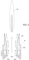
- a nozzle 25 is schematically represented in Figure 2 . It has a central inlet 25a connected with the supply of the gasifying agent and provided with a shrinkage 25b and a divergent section 25c downstream of the shrinkage 25b.
- a gas inlet 25d is obtained, connected with the pyrolysis gas outlet 15 of the first reactor 10. Thanks to Venturi effect, the passage of air in the central inlet 25a causes the aspiration of the pyrolysis gas 25d, while thanks to Coanda effect the gases are forced to follow the contour of the surface of the divergent section 25c. Overall, this results in an efficient mixing of the gasifying agent (air) with the pyrolysis gas.
- BF indicates a blue flame produced by the combustion of pyrolysis gas under sub-stoichiometric conditions.
- a supply of additional gasifying agent 27 is collocated at an intermediate level between the ejecting nozzles 25 and the reducing bed 31.
- the supply of additional gasifying agent 27 is connected to a blower outlet 19.
- the inlet of the blower 19 is connected, by means of control valves, to the steam outlet openings 10a of the first reactor 10 and to an air supply.
- the moisture content of the organic material, transformed into water vapor and superheated, can thus be at least partially used as an additional gasifying agent.
- the pyrogas is suctioned by the ejecting nozzles 25 which, thanks to Venturi effect together with Coanda effect, provide to mix the pyrogas with the oxygen contained in the gasifying agent under sub-stoichiometric conditions.
- the combustion air can be moistened with the steam taken from the pyrolysis reactor 10 to give rise to carbon reforming and Water/Gas Shift reaction.
- the pyrolysis gas treated in the manner described above is then driven through the grid or interface 23 and, then, through the reducer bed 31 composed of char from the pyrolysis reactor 10.
- the gases coming from the combustion chamber (mainly CO 2 and H 2 O) passing through this red-hot carbon bed undergo the subsequent reduction reactions (Boudouard reaction) obtaining the syngas with the desired composition (mainly CO, H 2 and, in lesser quantity, CH 4 ).
- the hot gases, after this phase, are conveyed in such a way as to wrap the pyrolysis reactor 10 transmitting the necessary heat to let the required reactions occur within it.
- additional chambers suitable to house materials may be provided with the function of catalyzing the process of breaking any tar still present, or to change the composition of the syngas itself by varying the percentages of gases present.
- measures can also be provided for a first cleaning with reference to dust abatement.
Landscapes
- Chemical & Material Sciences (AREA)
- Engineering & Computer Science (AREA)
- Oil, Petroleum & Natural Gas (AREA)
- Organic Chemistry (AREA)
- Combustion & Propulsion (AREA)
- Materials Engineering (AREA)
- Thermal Sciences (AREA)
- Physics & Mathematics (AREA)
- Chemical Kinetics & Catalysis (AREA)
- General Chemical & Material Sciences (AREA)
- Processing Of Solid Wastes (AREA)
- Gasification And Melting Of Waste (AREA)
- Organic Low-Molecular-Weight Compounds And Preparation Thereof (AREA)
- Catalysts (AREA)
Claims (7)
- Verfahren zur Vergasung von organischem Material, umfassend die folgenden Schritte:- Unterziehen ein organische Material einer Trocknungsschritt, um seinen Feuchtigkeitsgehalt zu verringern und trockenes organisches Material und Dampf zu erhalten, und Extrahieren des Dampfes,- Unterziehen das trockene organische Material einer Pyrolyse und Erzeugen ein Pyrolysegas und ein kohlenstoffhaltige feste Rückstand aus dem trockenen organischen Material, wobei das Pyrolysegas eine Teerfraktion enthält,- Trennen das Pyrolysegas von dem kohlenstoffhaltigen festen Rückstand, wobei das Trennen des Pyrolysegases die Extraktion des Pyrolysegases und dessen Beförderung getrennt von dem durch die Pyrolyse erzeugten kohlenstoffhaltigen festen Rückstand umfasst,- Unterziehen das Pyrolysegas einer thermochemischen Behandlung, und- nach der thermochemischen Behandlung, Verursachen das Durchdringen des behandelten Pyrolysegases durch ein Reduktionsbett (31), das aus dem durch die Pyrolyse erzeugten kohlenstoffhaltigen festen Rückstand besteht, und Erzeugen ein Synthesegas,wobei das Unterziehung von Pyrolysegas einer thermochemischen Behandlung umfasst:- Unterziehen das Pyrolysegas einer ersten Verbrennung mit einem Vergasungsmittel in unterstöchiometrischen Bedingungen durch Verwenden von Ausstoßdüsen (25), die unterhalb und stromaufwärts des Reduktionsbetts (31) angeordnet sind, und Erreichen das Cracken der Teerfraktion, die in dem Pyrolysegas enthalten ist, und- Unterziehen das Pyrolysegas einer zweiten Verbrennung, durch Einführung eines zusätzlichen Vergasungsmittels in eine Kammer (20"), die oberhalb und stromabwärts der Ausstoßdüsen (25) und stromaufwärts einer Schnittstelle (23) angeordnet ist, die die Kammer (20") vom Reduktionsbett (31) trennt, und Abschließen die Verbrennung der Teerfraktion, bis das Pyrolysegas vollständig in CO2, H2O(g) und Wärme umgewandelt ist;wobei das zusätzliche Vergasungsmittel zumindest teilweise aus dem in der Trocknungsschritt extrahierten Dampf besteht, wobei das behandelte Pyrolysegas durch Druckunterschiede durch diese Schnittstelle (23) zwischen der Kammer (20") und dem Reduktionsbett (31) nach oben bewegt wird und durch das Reduktionsbett (31) gespült wird, wobei diese Schnittstelle (23) als Stütze für dieses Reduktionsbett (31) dient, und wobei der während der Trocknungsschritt extrahierte Dampf in spezielle Kanäle geleitet, gezwungen durch Bereiche der Anlage mit hoher Temperatur zu durchlaufen und überhitzt wird, bevor er als zusätzliches Vergasungsmittel verwendet wird.
- Verfahren nach Anspruch 1, wobei die Ausstoßdüsen (25) auf Venturi- und Coanda-Effekten beruhen.
- Anlage zur Durchführung eines Verfahrens nach einem der vorhergehenden Ansprüche, umfassend:- einen ersten Schneckenreaktor (10), der mit horizontaler Rotationsachse (x) angeordnet ist, wobei der erste Reaktor (10) eingereichten ist, um das organische Material einer Trocknung und Pyrolyse zu unterziehen, und umfassend einen Dampfauslass (10a), einen Pyrolysegasauslass (15) und einen Auslass (17) für kohlenstoffhaltige feste Rückstände aufweist;- einen zweiten Reaktor (20), umfassend eine untere Kammer (20') und eine obere Kammer (20"), wobei in der unteren Kammer die Ausstoßdüsen (25) angeordnet sind, die mit dem Pyrolysegasauslass (15) des ersten Reaktors (10) verbunden sind, und wobei in der oberen Kammer eine zusätzliche Vergasungsmittelzufuhr (27) angeordnet ist;- und einen dritten Reaktor (30), der unterhalb des Auslasses (17) für kohlenstoffhaltige feste Rückstände des ersten Reaktors (10) und oberhalb des zweiten Reaktors (20) angeordnet ist, wobei der dritte Reaktor (30) das Reduktionsbett (31) umfasst, das aus den kohlenstoffhaltigen festen Rückständen besteht, die durch Schwerkraft durch den Auslass (17) für kohlenstoffhaltige feste Rückstände zugeführt werden können und durch die Schnittstelle (23) getragen werden, die ihn vom zweiten Reaktor (20) trennt;- wobei der dritte Reaktor (30) durch die Schnittstelle (23) in Fluidverbindung mit dem zweiten Reaktor (20) steht.
- Anlage nach Anspruch 3, wobei die Schnecke des ersten Reaktors (10) eingerichtet ist, um das organische Material in Kontakt mit den Wänden des Reaktors (10) zu halten.
- Anlage nach Anspruch 3 oder 4, wobei der erste Schneckenreaktor (10) eine Hohlwelle aufweist, die dazu geeignet ist, heiße Verbrennungsgase durch das organische Material zu leiten.
- Anlage nach einem der Ansprüche 3 bis 5, wobei der Dampfauslass (10a) des ersten Reaktors (10) mit der zusätzlichen Vergasungsmittelzufuhr (27) verbunden ist.
- Anlage nach einem der Ansprüche 3 bis 6, wobei die das Reduzierbett (31) tragende Schnittstelle (23) als perforiertes, gasdurchlässiges Gitter ausgebildet ist.
Applications Claiming Priority (2)
| Application Number | Priority Date | Filing Date | Title |
|---|---|---|---|
| IT102020000025321A IT202000025321A1 (it) | 2020-10-26 | 2020-10-26 | Processo di gassificazione di materiale organico e impianto per attuare un tale processo |
| PCT/IT2021/050345 WO2022091152A1 (en) | 2020-10-26 | 2021-10-26 | Process for gasifying an organic material and plant for carrying out said process |
Publications (3)
| Publication Number | Publication Date |
|---|---|
| EP4232525A1 EP4232525A1 (de) | 2023-08-30 |
| EP4232525C0 EP4232525C0 (de) | 2024-08-07 |
| EP4232525B1 true EP4232525B1 (de) | 2024-08-07 |
Family
ID=74184735
Family Applications (1)
| Application Number | Title | Priority Date | Filing Date |
|---|---|---|---|
| EP21815279.1A Active EP4232525B1 (de) | 2020-10-26 | 2021-10-26 | Verfahren zur vergasung von organischem material und anlage zur durchführung des verfahrens |
Country Status (6)
| Country | Link |
|---|---|
| US (1) | US12312545B2 (de) |
| EP (1) | EP4232525B1 (de) |
| CA (1) | CA3196638A1 (de) |
| ES (1) | ES2992347T3 (de) |
| IT (1) | IT202000025321A1 (de) |
| WO (1) | WO2022091152A1 (de) |
Families Citing this family (3)
| Publication number | Priority date | Publication date | Assignee | Title |
|---|---|---|---|---|
| CN115386388B (zh) * | 2022-09-06 | 2024-05-10 | 陕西西卫智慧环境科技有限公司 | 一种生物质热解制备混合燃气及生物质碳装置 |
| CN115873639A (zh) * | 2022-12-02 | 2023-03-31 | 北京清创晋华科技有限公司 | 一种碳物质气化余热热解装置及方法 |
| DE102024111037A1 (de) * | 2024-04-19 | 2025-10-23 | Rheinisch-Westfälische Technische Hochschule Aachen, abgekürzt RWTH Aachen, Körperschaft des öffentlichen Rechts | System und Verfahren zur Erzeugung von Synthesegas aus kohlenstoffhaltigen Feststoffen und Schlämmen |
Family Cites Families (17)
| Publication number | Priority date | Publication date | Assignee | Title |
|---|---|---|---|---|
| US3871839A (en) * | 1972-10-12 | 1975-03-18 | Air Prod & Chem | Method of feeding solid carbonaceous material to a high temperature reaction zone |
| US4927430A (en) * | 1988-05-26 | 1990-05-22 | Albert Calderon | Method for producing and treating coal gases |
| US20020020112A1 (en) * | 2000-07-25 | 2002-02-21 | Scotlund Stivers | Process and apparatus for manufacturing fuel gas and liquid fuels from trash, other waste materials and solid fuels |
| EP1312662A3 (de) * | 2001-05-07 | 2003-09-24 | Cirad-Foret | Verfahren zur Vergasung von Biomasse, Vorrichtung und Anwendung |
| CA2501841C (en) * | 2004-03-23 | 2012-07-10 | Central Research Institute Of Electric Power Industry | Carbonization and gasification of biomass and power generation system |
| JP4790412B2 (ja) * | 2005-12-28 | 2011-10-12 | 中外炉工業株式会社 | バイオマスガス化装置 |
| DE102008014799A1 (de) * | 2008-03-18 | 2009-09-24 | Karl-Heinz Tetzlaff | Verfahren und Vorrichtung zur Herstellung von Synthesegas aus Biomasse |
| SE0801266A0 (sv) * | 2008-05-29 | 2009-12-21 | Blasiak Wlodzimierz | Tvåstegsförgasare som använder förupphettad ånga av hög temperatur |
| US8858900B2 (en) * | 2008-10-14 | 2014-10-14 | Intellergy, Inc. | Process and system for converting waste to energy without burning |
| US20100319255A1 (en) * | 2009-06-18 | 2010-12-23 | Douglas Struble | Process and system for production of synthesis gas |
| DE102009047445A1 (de) | 2009-12-03 | 2011-06-09 | Burkhardt Gmbh | Anlage zum Erzeugen eines Produktgases aus organischen Einsatzstoffen |
| CN103119135B (zh) * | 2010-07-27 | 2017-06-30 | 科廷科技大学 | 气化含碳材料的方法及气化系统 |
| FR2965816B1 (fr) * | 2010-10-12 | 2014-04-25 | S3D | Dispositif pour la transformation d'un combustible |
| US20120161451A1 (en) * | 2010-12-22 | 2012-06-28 | Synterra Energy | Production of liquid fuel or electric power from synthesis gas in an integrated platform |
| IT1406771B1 (it) * | 2010-12-23 | 2014-03-07 | Sea Marconi Technologies Di Vander Tumiatti S A S | Impianto modulare per la conduzione di procedimenti di conversione di matrici carboniose |
| AT514400B1 (de) | 2013-05-31 | 2015-05-15 | Cleanstgas Gmbh | Anlage zum Vergasen von stückigen Brennstoffen |
| CN111278953A (zh) * | 2017-10-12 | 2020-06-12 | 丹麦技术大学 | 一种气化单元、生产产品气的方法和这种方法的应用 |
-
2020
- 2020-10-26 IT IT102020000025321A patent/IT202000025321A1/it unknown
-
2021
- 2021-10-26 EP EP21815279.1A patent/EP4232525B1/de active Active
- 2021-10-26 CA CA3196638A patent/CA3196638A1/en active Pending
- 2021-10-26 ES ES21815279T patent/ES2992347T3/es active Active
- 2021-10-26 WO PCT/IT2021/050345 patent/WO2022091152A1/en not_active Ceased
- 2021-10-26 US US18/033,933 patent/US12312545B2/en active Active
Also Published As
| Publication number | Publication date |
|---|---|
| US12312545B2 (en) | 2025-05-27 |
| CA3196638A1 (en) | 2022-05-05 |
| WO2022091152A1 (en) | 2022-05-05 |
| EP4232525A1 (de) | 2023-08-30 |
| EP4232525C0 (de) | 2024-08-07 |
| US20240026237A1 (en) | 2024-01-25 |
| IT202000025321A1 (it) | 2022-04-26 |
| ES2992347T3 (es) | 2024-12-11 |
Similar Documents
| Publication | Publication Date | Title |
|---|---|---|
| EP4232525B1 (de) | Verfahren zur vergasung von organischem material und anlage zur durchführung des verfahrens | |
| CA2727827C (en) | Generating clean syngas from biomass | |
| CA2377774C (en) | A method and an apparatus for the pyrolysis and gasification of organic substances or mixtures of organic substances | |
| CN107254332B (zh) | 气化含碳材料的方法及气化系统 | |
| US4385905A (en) | System and method for gasification of solid carbonaceous fuels | |
| CA2429512C (en) | Small scale high throughput biomass gasification system and method | |
| US7819070B2 (en) | Method and apparatus for generating combustible synthesis gas | |
| US20050095183A1 (en) | Process and apparatus for biomass gasification | |
| JP2011522084A (ja) | 二段高温予熱スチームガス化炉 | |
| US20090277090A1 (en) | Gas distribution arrangement for a rotary reactor | |
| US9255231B2 (en) | Method and apparatus for fixed bed gasification | |
| KR101632146B1 (ko) | 바이오매스 가스화 장치 | |
| CN101139532A (zh) | 固体燃料解耦流化床气化方法及气化装置 | |
| CN101230281A (zh) | 一种固体生物质半水煤气发生炉 | |
| WO2007081296A1 (en) | Downdraft/updraft gasifier for syngas production from solid waste | |
| US9862899B2 (en) | Gas distribution arrangement for rotary reactor | |
| KR102250690B1 (ko) | 바이오매스를 이용한 백탄 제조장치 및 이를 갖는 바이오매스 처리설비 | |
| KR100695908B1 (ko) | 목질계 바이오매스 가스화 장치 | |
| Sheng | Biomass gasifiers: from waste to energy production | |
| JP3559163B2 (ja) | バイオマスと化石燃料を用いたガス化方法 | |
| CZ295171B6 (cs) | Třízonový zplyňovač biomasy rostlinného původu s obchvatem | |
| KR102402473B1 (ko) | 통합형 바이오매스 반탄화 가스화 장치 및 가스화 방법 | |
| EP4151706B1 (de) | Verfahren und vorrichtung zur herstellung eines teer- und staubarmen produktgases | |
| EA014373B1 (ru) | Способ газификации твердого углеродсодержащего топлива, в том числе углеродсодержащих отходов и газогенератор | |
| CN117757497A (zh) | 一种外热立式连续煤热解-气化装置及联产系统 |
Legal Events
| Date | Code | Title | Description |
|---|---|---|---|
| STAA | Information on the status of an ep patent application or granted ep patent |
Free format text: STATUS: UNKNOWN |
|
| STAA | Information on the status of an ep patent application or granted ep patent |
Free format text: STATUS: THE INTERNATIONAL PUBLICATION HAS BEEN MADE |
|
| PUAI | Public reference made under article 153(3) epc to a published international application that has entered the european phase |
Free format text: ORIGINAL CODE: 0009012 |
|
| STAA | Information on the status of an ep patent application or granted ep patent |
Free format text: STATUS: REQUEST FOR EXAMINATION WAS MADE |
|
| 17P | Request for examination filed |
Effective date: 20230418 |
|
| AK | Designated contracting states |
Kind code of ref document: A1 Designated state(s): AL AT BE BG CH CY CZ DE DK EE ES FI FR GB GR HR HU IE IS IT LI LT LU LV MC MK MT NL NO PL PT RO RS SE SI SK SM TR |
|
| DAV | Request for validation of the european patent (deleted) | ||
| DAX | Request for extension of the european patent (deleted) | ||
| GRAP | Despatch of communication of intention to grant a patent |
Free format text: ORIGINAL CODE: EPIDOSNIGR1 |
|
| STAA | Information on the status of an ep patent application or granted ep patent |
Free format text: STATUS: GRANT OF PATENT IS INTENDED |
|
| INTG | Intention to grant announced |
Effective date: 20240227 |
|
| GRAS | Grant fee paid |
Free format text: ORIGINAL CODE: EPIDOSNIGR3 |
|
| GRAA | (expected) grant |
Free format text: ORIGINAL CODE: 0009210 |
|
| STAA | Information on the status of an ep patent application or granted ep patent |
Free format text: STATUS: THE PATENT HAS BEEN GRANTED |
|
| AK | Designated contracting states |
Kind code of ref document: B1 Designated state(s): AL AT BE BG CH CY CZ DE DK EE ES FI FR GB GR HR HU IE IS IT LI LT LU LV MC MK MT NL NO PL PT RO RS SE SI SK SM TR |
|
| REG | Reference to a national code |
Ref country code: GB Ref legal event code: FG4D |
|
| REG | Reference to a national code |
Ref country code: CH Ref legal event code: EP |
|
| REG | Reference to a national code |
Ref country code: IE Ref legal event code: FG4D |
|
| REG | Reference to a national code |
Ref country code: DE Ref legal event code: R096 Ref document number: 602021017008 Country of ref document: DE |
|
| U01 | Request for unitary effect filed |
Effective date: 20240902 |
|
| U07 | Unitary effect registered |
Designated state(s): AT BE BG DE DK EE FI FR IT LT LU LV MT NL PT RO SE SI Effective date: 20241004 |
|
| U20 | Renewal fee for the european patent with unitary effect paid |
Year of fee payment: 4 Effective date: 20241016 |
|
| REG | Reference to a national code |
Ref country code: ES Ref legal event code: FG2A Ref document number: 2992347 Country of ref document: ES Kind code of ref document: T3 Effective date: 20241211 |
|
| PG25 | Lapsed in a contracting state [announced via postgrant information from national office to epo] |
Ref country code: NO Free format text: LAPSE BECAUSE OF FAILURE TO SUBMIT A TRANSLATION OF THE DESCRIPTION OR TO PAY THE FEE WITHIN THE PRESCRIBED TIME-LIMIT Effective date: 20241107 |
|
| PG25 | Lapsed in a contracting state [announced via postgrant information from national office to epo] |
Ref country code: GR Free format text: LAPSE BECAUSE OF FAILURE TO SUBMIT A TRANSLATION OF THE DESCRIPTION OR TO PAY THE FEE WITHIN THE PRESCRIBED TIME-LIMIT Effective date: 20241108 Ref country code: PL Free format text: LAPSE BECAUSE OF FAILURE TO SUBMIT A TRANSLATION OF THE DESCRIPTION OR TO PAY THE FEE WITHIN THE PRESCRIBED TIME-LIMIT Effective date: 20240807 |
|
| PG25 | Lapsed in a contracting state [announced via postgrant information from national office to epo] |
Ref country code: IS Free format text: LAPSE BECAUSE OF FAILURE TO SUBMIT A TRANSLATION OF THE DESCRIPTION OR TO PAY THE FEE WITHIN THE PRESCRIBED TIME-LIMIT Effective date: 20241207 |
|
| PG25 | Lapsed in a contracting state [announced via postgrant information from national office to epo] |
Ref country code: HR Free format text: LAPSE BECAUSE OF FAILURE TO SUBMIT A TRANSLATION OF THE DESCRIPTION OR TO PAY THE FEE WITHIN THE PRESCRIBED TIME-LIMIT Effective date: 20240807 |
|
| PG25 | Lapsed in a contracting state [announced via postgrant information from national office to epo] |
Ref country code: RS Free format text: LAPSE BECAUSE OF FAILURE TO SUBMIT A TRANSLATION OF THE DESCRIPTION OR TO PAY THE FEE WITHIN THE PRESCRIBED TIME-LIMIT Effective date: 20241107 |
|
| PG25 | Lapsed in a contracting state [announced via postgrant information from national office to epo] |
Ref country code: RS Free format text: LAPSE BECAUSE OF FAILURE TO SUBMIT A TRANSLATION OF THE DESCRIPTION OR TO PAY THE FEE WITHIN THE PRESCRIBED TIME-LIMIT Effective date: 20241107 Ref country code: PL Free format text: LAPSE BECAUSE OF FAILURE TO SUBMIT A TRANSLATION OF THE DESCRIPTION OR TO PAY THE FEE WITHIN THE PRESCRIBED TIME-LIMIT Effective date: 20240807 Ref country code: NO Free format text: LAPSE BECAUSE OF FAILURE TO SUBMIT A TRANSLATION OF THE DESCRIPTION OR TO PAY THE FEE WITHIN THE PRESCRIBED TIME-LIMIT Effective date: 20241107 Ref country code: IS Free format text: LAPSE BECAUSE OF FAILURE TO SUBMIT A TRANSLATION OF THE DESCRIPTION OR TO PAY THE FEE WITHIN THE PRESCRIBED TIME-LIMIT Effective date: 20241207 Ref country code: HR Free format text: LAPSE BECAUSE OF FAILURE TO SUBMIT A TRANSLATION OF THE DESCRIPTION OR TO PAY THE FEE WITHIN THE PRESCRIBED TIME-LIMIT Effective date: 20240807 Ref country code: GR Free format text: LAPSE BECAUSE OF FAILURE TO SUBMIT A TRANSLATION OF THE DESCRIPTION OR TO PAY THE FEE WITHIN THE PRESCRIBED TIME-LIMIT Effective date: 20241108 |
|
| PG25 | Lapsed in a contracting state [announced via postgrant information from national office to epo] |
Ref country code: SM Free format text: LAPSE BECAUSE OF FAILURE TO SUBMIT A TRANSLATION OF THE DESCRIPTION OR TO PAY THE FEE WITHIN THE PRESCRIBED TIME-LIMIT Effective date: 20240807 |
|
| PG25 | Lapsed in a contracting state [announced via postgrant information from national office to epo] |
Ref country code: CZ Free format text: LAPSE BECAUSE OF FAILURE TO SUBMIT A TRANSLATION OF THE DESCRIPTION OR TO PAY THE FEE WITHIN THE PRESCRIBED TIME-LIMIT Effective date: 20240807 |
|
| PG25 | Lapsed in a contracting state [announced via postgrant information from national office to epo] |
Ref country code: SK Free format text: LAPSE BECAUSE OF FAILURE TO SUBMIT A TRANSLATION OF THE DESCRIPTION OR TO PAY THE FEE WITHIN THE PRESCRIBED TIME-LIMIT Effective date: 20240807 |
|
| PLBE | No opposition filed within time limit |
Free format text: ORIGINAL CODE: 0009261 |
|
| STAA | Information on the status of an ep patent application or granted ep patent |
Free format text: STATUS: NO OPPOSITION FILED WITHIN TIME LIMIT |
|
| PG25 | Lapsed in a contracting state [announced via postgrant information from national office to epo] |
Ref country code: MC Free format text: LAPSE BECAUSE OF FAILURE TO SUBMIT A TRANSLATION OF THE DESCRIPTION OR TO PAY THE FEE WITHIN THE PRESCRIBED TIME-LIMIT Effective date: 20240807 |
|
| 26N | No opposition filed |
Effective date: 20250508 |
|
| PGFP | Annual fee paid to national office [announced via postgrant information from national office to epo] |
Ref country code: GB Payment date: 20250911 Year of fee payment: 5 |
|
| PGFP | Annual fee paid to national office [announced via postgrant information from national office to epo] |
Ref country code: IE Payment date: 20250919 Year of fee payment: 5 |
|
| U20 | Renewal fee for the european patent with unitary effect paid |
Year of fee payment: 5 Effective date: 20250916 |
|
| REG | Reference to a national code |
Ref country code: CH Ref legal event code: U11 Free format text: ST27 STATUS EVENT CODE: U-0-0-U10-U11 (AS PROVIDED BY THE NATIONAL OFFICE) Effective date: 20251101 |
|
| PGFP | Annual fee paid to national office [announced via postgrant information from national office to epo] |
Ref country code: CH Payment date: 20251101 Year of fee payment: 5 |
|
| PG25 | Lapsed in a contracting state [announced via postgrant information from national office to epo] |
Ref country code: CY Free format text: LAPSE BECAUSE OF FAILURE TO SUBMIT A TRANSLATION OF THE DESCRIPTION OR TO PAY THE FEE WITHIN THE PRESCRIBED TIME-LIMIT; INVALID AB INITIO Effective date: 20211026 |
|
| PGFP | Annual fee paid to national office [announced via postgrant information from national office to epo] |
Ref country code: ES Payment date: 20251104 Year of fee payment: 5 |
|
| PG25 | Lapsed in a contracting state [announced via postgrant information from national office to epo] |
Ref country code: HU Free format text: LAPSE BECAUSE OF FAILURE TO SUBMIT A TRANSLATION OF THE DESCRIPTION OR TO PAY THE FEE WITHIN THE PRESCRIBED TIME-LIMIT; INVALID AB INITIO Effective date: 20211026 |