EP4230864B1 - Rohrsicherungssystem für schwerlastfahrzeuge und verfahren zur lagerung eines rohrs auf einem schwerlastfahrzeug - Google Patents
Rohrsicherungssystem für schwerlastfahrzeuge und verfahren zur lagerung eines rohrs auf einem schwerlastfahrzeug Download PDFInfo
- Publication number
- EP4230864B1 EP4230864B1 EP22158095.4A EP22158095A EP4230864B1 EP 4230864 B1 EP4230864 B1 EP 4230864B1 EP 22158095 A EP22158095 A EP 22158095A EP 4230864 B1 EP4230864 B1 EP 4230864B1
- Authority
- EP
- European Patent Office
- Prior art keywords
- pipe
- bearing shell
- support member
- bearing
- securing system
- Prior art date
- Legal status (The legal status is an assumption and is not a legal conclusion. Google has not performed a legal analysis and makes no representation as to the accuracy of the status listed.)
- Active
Links
Images



Classifications
-
- B—PERFORMING OPERATIONS; TRANSPORTING
- B60—VEHICLES IN GENERAL
- B60P—VEHICLES ADAPTED FOR LOAD TRANSPORTATION OR TO TRANSPORT, TO CARRY, OR TO COMPRISE SPECIAL LOADS OR OBJECTS
- B60P7/00—Securing or covering of load on vehicles
- B60P7/06—Securing of load
- B60P7/08—Securing to the vehicle floor or sides
- B60P7/12—Securing to the vehicle floor or sides the load being tree-trunks, beams, drums, tubes, or the like
-
- B—PERFORMING OPERATIONS; TRANSPORTING
- B60—VEHICLES IN GENERAL
- B60P—VEHICLES ADAPTED FOR LOAD TRANSPORTATION OR TO TRANSPORT, TO CARRY, OR TO COMPRISE SPECIAL LOADS OR OBJECTS
- B60P3/00—Vehicles adapted to transport, to carry or to comprise special loads or objects
- B60P3/40—Vehicles adapted to transport, to carry or to comprise special loads or objects for carrying long loads, e.g. with separate wheeled load supporting elements
-
- B—PERFORMING OPERATIONS; TRANSPORTING
- B60—VEHICLES IN GENERAL
- B60P—VEHICLES ADAPTED FOR LOAD TRANSPORTATION OR TO TRANSPORT, TO CARRY, OR TO COMPRISE SPECIAL LOADS OR OBJECTS
- B60P7/00—Securing or covering of load on vehicles
- B60P7/06—Securing of load
- B60P7/135—Securing or supporting by load bracing means
-
- F—MECHANICAL ENGINEERING; LIGHTING; HEATING; WEAPONS; BLASTING
- F03—MACHINES OR ENGINES FOR LIQUIDS; WIND, SPRING, OR WEIGHT MOTORS; PRODUCING MECHANICAL POWER OR A REACTIVE PROPULSIVE THRUST, NOT OTHERWISE PROVIDED FOR
- F03D—WIND MOTORS
- F03D13/00—Assembly, mounting or commissioning of wind motors; Arrangements specially adapted for transporting wind motor components
- F03D13/40—Arrangements or methods specially adapted for transporting wind motor components
- F03D13/402—Arrangements or methods specially adapted for transporting wind motor components for transporting or storing towers
Definitions
- the invention relates to a pipe securing system for heavy-duty vehicles according to the preamble of claim 1 and to a method for storing a pipe on a heavy-duty vehicle according to the preamble of claim 11.
- FIG. 1 shows a modular heavy-duty vehicle 30 with several crossbeams 2.
- a crossbeam 2 is mounted on top of the modular heavy-duty vehicle 30 and thus reduces the free space between the crossbeam 2 and the pipe wall 41.
- the pipe which is often also reduced in wall thickness, especially in the area of storage, i.e. in the middle area of the pipe, requires storage so that the pipe is not plastically deformed or deformed by its own weight. This leads to challenges in placing a required support structure under the pipe and on the crossbeams, especially during transport from production or when the pipe is placed on the bearing blocks.
- US 2005/0286985 A1 describes a system for supporting a cylindrical object, such as a tank.
- the supports are designed as side bearing blocks, with each support having a curved part adjacent to the cylindrical object and a base section.
- the independence of the supports and their adjustability in relation to the base make them suitable for use with tanks of various sizes.
- EP 3 342 637 A1 is a support system for transporting tower elements of a wind turbine.
- the support system comprises a retaining clamp with several curved and spaced-apart slots.
- the slots are shaped to correspond to a flange provided on the pipe elements.
- Plug-in plates are arranged in the slots, which are shaped to correspond to the holes in the flange.
- the retaining clamps are attached to the pipe with screws and nuts.
- a variety of brackets can be used to enable the pipes to be stacked during transport.
- the retaining clamps offer a high level of security, but are complex to install and are only suitable for pipes with flanges and are not designed for short-term use, e.g. during transport on the production site.
- the US 2019/285057 A1 discloses a generic pipe securing system for heavy-duty vehicles.
- the object of the invention is to provide a pipe securing system for heavy-duty vehicles and a method for securing a pipe with the pipe securing system, which overcomes the above disadvantages and is particularly suitable for pipes with large diameters of at least 6 m, can be used in conditions of little free space and space and for short-term use such as transport or storage on the production site and enables safe and damage-free storage of the pipe.
- the pipe securing system for heavy-duty vehicles has at least one support beam and at least one bearing device.
- the support beam is at least partially plate-shaped or cuboid-shaped and has an overall width that is adapted to the overall width of a modular heavy-duty vehicle.
- the support beam has a load capacity of at least 500 t.
- the support beam is preferably made of metal, particularly preferably steel, and is equipped with a safety device to prevent slipping.
- the support beam can be provided with lifting devices, such as lifting eyes.
- the bearing device is arranged on the support beam in the operating state.
- the bearing device is a bearing shell.
- the bearing shell has a bottom and a top and two narrow transverse sides.
- the narrow transverse sides connect the bottom and the top, with the bottom of the bearing shell forming a base and the top of the bearing shell having a channel-shaped recess to accommodate a horizontal pipe.
- the channel-shaped recess extends at least partially between the two long sides of the bearing shell and the longitudinal axis of the channel runs transversely to the longitudinal axis of the bearing shell.
- the bearing shell is made at least partially of wood.
- the bearing shell has at least one lateral load-bearing device, which is arranged parallel to the longitudinal axis of the bearing shell and transverse to the longitudinal axis of a pipe placed on top. In the resting state, the bearing shell is arranged next to the support beam.
- a load-bearing device is a component that is not part of the lifting device and that enables a load to be grasped.
- the lateral load-bearing devices are preferably designed as metal profiles that are attached to the side of the bearing device.
- the pipe is, for example, a tower element, such as a monopile, for a wind turbine and is cylindrical or conical or has cylindrical and conical sections.
- the pipe securing system is used to hold pipes and pipe sections with a diameter of at least 6 m, preferably a diameter of 8 to 10 m.
- the inclusion of pipes with larger diameters of e.g. 11.5 to 12 m is also conceivable.
- the bearing shell has a surface on its upper side for receiving a pipe, this surface being curved in order to receive a horizontal pipe.
- the curvature of the surface leads to the formation of a groove, the curvature being adapted to the curvature of the pipe resting on it.
- a groove corresponds to a cut pipe or a cylinder segment, the outer surface, the curved part of the surface, extending to the bottom of the bearing shell and the cut surface running in a plane with the upper side of the bearing shell.
- the groove-shaped recess is preferably arranged in the middle of the bearing shell, so that the distance from the lowest point of the groove to both transverse sides is the same.
- the area of the bearing shell with the groove-shaped recess is continuous, i.e. the surface of the groove-shaped recess is formed from one piece.
- the curved surfaces ensure that the pipe is supported over a significant portion of its width.
- the bearing shell preferably has a continuous surface that is monolithically formed from one part, i.e. one-piece.
- the bearing shell preferably consists of solid material, at least in the area below the channel-shaped recess.
- the bearing shell is made of wood, preferably glued laminated timber.
- the bearing shell can also consist of plastic, e.g. polyurethane plastic, or hybrid materials made of wood and PU plastic.
- the middle web of the bearing shell is selected so that the bearing shell has enough stability when lifted from the outside with the lifting device, but does not take up too much free space under the pipe.
- the bearing shell has a diameter in the area of the curved surface that results in a permissible stress on the pipe that excludes permanent plastic deformation during transport. For pipes with different diameters, different bearing shells are preferably used, the channel-shaped recesses of which have different diameters.
- the bearing device preferably has the same height as the support beam or is higher than the support beam depending on the space under the pipe, i.e. depending on the height of the free space between the pipe wall and the top of the support beam.
- the pipe safety device is used on a modular heavy-duty vehicle, a so-called SPMT (Self-propelled Modular Transporter).
- SPMT Self-propelled Modular Transporter
- These modular heavy-duty vehicles are modular vehicles with their own drive, i.e. self-propelled, with several axles.
- the pipe securing system has a lifting device.
- the lifting device has a receptacle for the load-carrying means, so that the lifting device can lift the load-carrying means or the load-carrying means can be connected to the lifting device.
- the receptacle can be, for example, a plate or a sling.
- the lifting device is preferably electric, mechanical or hydraulic, particularly preferably an electric, mechanical or hydraulic jack.
- the lifting device can be arranged on the transverse side of the loading device and the transverse side of the support beam next to the support beam. When designed as a jack, the lifting device preferably has rollers.
- the pipe safety system has an empty state in which it is not used and no pipe is resting on the pipe safety system and an operating state in which a pipe is resting on the pipe safety system and is secured by it.
- the bearing shell is preferably arranged centrally on the support beam in the operating state and is preferably the same distance from both transverse sides of the support beam and the two longitudinal sides of the support beam. The bearing shell rests fully on the support beam or stands on the support beam, i.e. it is completely supported by the cross beam without lateral overhangs to improve stability and force transfer.
- the support carrier has position markers on its upper side for the correct position of the bearing shell on the support carrier.
- a load-bearing device preferably made of metal profiles, is applied to the bearing shells, preferably made predominantly of glued laminated timber.
- the lifting device is positioned in an outer edge area of the heavy-duty vehicle next to the bearing shell relative to the load-bearing device.
- the bearing shells which are positioned next to the support beams before transport, can be lifted for use using the lifting device and pushed onto the cross beams by moving the lifting device sideways.
- the bearing shell is then lowered into the correct position, e.g. using position markers in the correct central position. After completing these process steps for all bearing points, the pipe is lowered or the heavy-duty vehicle performs a lifting movement so that the pipe lies completely in the bearing shells and is evenly supported.
- the support beams are built on top of the heavy-duty vehicle and thus reduce the free space between the cross beam and the pipe wall. This leads to challenges in placing a required support structure under the pipe and on the cross beams, especially during transport from production and when the pipe has been placed on the bearing blocks.
- the pipe securing device according to the invention and the method according to the invention enable, despite reduced free space under the pipe and the limited accessibility in production, a space-saving system that does not require external lifting equipment such as forklifts or cranes and can be used both in a production hall and outdoors.
- the height of a support beam is usually at least 300 mm, which results in a small amount of free space underneath the pipe.
- a bearing shell is placed to the side of a support beam on the loading area of a heavy-duty vehicle before the heavy-duty vehicle drives under the pipe.
- the bearing shell preferably of a comparable height to the support beam or higher, depending on the space between the support beam and the pipe wall, is lifted using a lifting device, such as a car jack, and moved transversely on rollers in the longitudinal direction of the pipe using the lifting device and positioned on the support beam.
- the rollers are preferably designed in such a way that they can be moved easily and manually. This means that the use of heavy equipment such as a forklift or crane is not necessary.
- Figure 1 shows a pipe 40 for a wind turbine, which is also referred to as a monopile, made of several pipe sections 44 that are welded together.
- the pipe 40 lies on two rotating devices 42, each of which is placed in the area of the pipe ends.
- a modular heavy-duty vehicle 30 is placed under the middle area of the pipe 40.
- Several support beams 2 are arranged on the loading area 31. According to the prior art, the pipe is placed on the support beam and stored after the pipe has been lowered or the loading area of the heavy-duty vehicle has been raised.
- Figure 2 shows a sectional view of Figure 1 along the section line AA.
- the pipe wall 41 rests on two rollers 43 of the rotating device 42.
- a support beam 2 is arranged on the loading area of the modular heavy-duty vehicle 30.
- a free space F can be seen between the pipe wall 41 and the top of the support beam 2.
- the heavy-duty vehicle 30 is multi-axle and has a large number of tires 32.
- FIG 3 shows a section of a loading area 31 of a modular heavy-duty vehicle 30.
- the heavy-duty vehicle is made up of several modules 30a.
- Two pipe securing systems 1 are placed on the loading area 31.
- the left pipe securing system 1 is in the empty state and the right pipe securing system 1 is in the operating state.
- a bearing shell 3a is placed next to a cross member 2a.
- the bearing shell 3a has a base 4 on its underside, which stands on the loading area 31.
- the bearing shell has a recess 5, the curvature of which corresponds to the curvature of the pipe wall in order to be able to hold the pipe.
- a load-carrying device 7 in the form of a metal profile is attached to each of the two transverse sides 6 of the bearing shell.
- a lifting device 8 is arranged below the load-carrying device 7. In the middle, the lifting device has a holder 9 for the load-carrying device 7 in the form of a plate.
- the lifting device 8, here a car jack has rollers 10 on its four corners.
- the right pipe securing system is shown in the operating state.
- a bearing shell 3b is arranged on the support beam 2b.
- the base 4 of the bearing shell 3b stands on the support beam 2b.
- the lateral load-bearing devices 7 each lie on the two lifting devices 8, which are rolled next to the support beam 2b.
- Figure 4 also shows, in a semi-oblique view, two pipe securing systems on the loading area 31 of a modular heavy-duty vehicle 30.
- the lifting devices are not shown for either pipe securing system.
- the left pipe securing system 1 is in the empty state and the right pipe securing system 1 is in the operating state.
- a bearing shell 3 is placed next to the cross member 2.
- the bearing shell 3 has a recess 5 on the top.
- the higher side areas of the bearing shell 11 next to the recess have the same height as the support beam 2.
- a load-bearing device 7 in the form of a metal profile is attached to both transverse sides 6 of the bearing shell, the top of which here also corresponds to the top of the non-hollowed out side areas 11.
- the right pipe securing system is shown in the operating state.
- the bearing shell 3 stands on the support beam 2.
- the base 4 of the bearing shell 3 stands on the support beam 2.
- Figure 5 shows the two pipe safety systems from Figure 4 in the same perspective but with pipe.
- the right pipe safety system in the operating state carries the pipe that in the recess 5 of the bearing shell 3.
- the left pipe securing system in the empty state the free space F between the pipe wall and the support beam 2 can be seen.
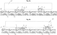
- FIGs 6a and 6b A side view of two pipe safety systems is shown in the operating state and in the empty state.
- the pipe safety systems are shown without a lifting device.
- the bearing shell 3 In the left pipe safety system, the bearing shell 3 is next to the support beam 2 on the loading area 31. The bearing shell has the same height as the support beam.
- the bearing shell 3 In the right pipe safety system in the operating state, the bearing shell 3 is on the support beam 2 and the pipe 40 is in the bearing shell.
- the pipe 40 is only shown in part here.
- Figure 6b The pipe 40 is only shown in part.
- the lifting devices 8 are shown. In the left pipe securing system, the lifting device 8 is folded up next to the bearing shell 3. In the right pipe securing system, the lifting device 8 is placed next to the cross member 2 and the load-carrying device 7 of the bearing shell is still on the lifting device 8.
- Figure 7 shows a pipe securing system in a rear view without a pipe in place.
- the bearing shell 3 stands on the support beam 2, which in turn stands on the loading area 31 of the heavy-duty vehicle. In the middle area, the bearing shell 3 has a recess 5, while the two side areas 11 are raised.
- the load-carrying devices 7 are attached to the transverse sides.
- Figure 8 shows the same view as Figure 7 , whereby a section of a pipe 40 is also shown, which lies in the bearing shell 3. Due to the curvature of the bearing shell in the area of the recess, the pipe is secured against rolling away as well as against mechanical damage.
Landscapes
- Engineering & Computer Science (AREA)
- Mechanical Engineering (AREA)
- Transportation (AREA)
- Health & Medical Sciences (AREA)
- Public Health (AREA)
- Chemical & Material Sciences (AREA)
- Combustion & Propulsion (AREA)
- Sustainable Energy (AREA)
- General Engineering & Computer Science (AREA)
- Sustainable Development (AREA)
- Life Sciences & Earth Sciences (AREA)
- Forklifts And Lifting Vehicles (AREA)
- Loading Or Unloading Of Vehicles (AREA)
Description
- Gegenstand der Erfindung ist ein Rohrsicherungssystem für Schwerlastfahrzeuge gemäß dem Oberbegriff von Anspruch 1 und in Verfahren zur Lagerung eines Rohrs auf einem Schwerlastfahrzeug gemäß dem Oberbegriff von Anspruch 11.
- Großrohre, insbesondere aus längs- und rundnahtgeschweißten Stahlblechen, mit einem erheblichen Durchmesser finden beispielsweise beim Fundamentbau für Offshore-Anlagen, insbesondere Windkraftanlagen, Anwendung. Für Großrohre, die im Offshore-Bereich eingesetzt werden, z.B. als Monopiles oder Tripode, sind Rohrdurchmesser von größer 6 m und mittlerweile größer als 9 m keine Seltenheit mehr. Diese Großrohre haben ein hohes Eigengewicht von mehreren Tausend Tonnen und sind im Verhältnis zum Rohrdurchmesser sehr dünnwandig ausgebildet.
- Die Transportfahrzeuge für solche Großrohre müssen daher eine ausreichende Tragfähigkeit aufweisen, um die sehr großen, langen und schweren Rohre tragen zu können. Der Transport der Rohre an Land erfolgt üblicherweise mit modularen Schwerlastfahrzeugen, sogenannten SPMT (Self-Propelled Modular Transporter). Beim Transport großer Rohre werden häufig mehrere der modularen Schwerlastfahrzeuge nebeneinander positioniert und miteinander verbunden. Eine Lastverteilung erfolgt z.B. mittels sogenannter Querträger, auf denen das Rohr abgelegt wird.
Figur 1 zeigt ein modulares Schwerlastfahrzeug 30 mit mehreren Querträgern 2. Ein Querträger 2 baut oben auf dem modularen Schwerlastfahrzeug 30 auf und reduziert somit den Freiraum zwischen Querträger 2 und Rohrwandung 41. Das Rohr, das vor allem im Bereich der Lagerung, also im Mittenbereich des Rohrs, zusätzlich häufig in der Wanddicke reduziert ist, erfordert eine Lagerung, sodass sich das Rohr nicht durch sein Eigengewicht plastisch deformiert oder verformt wird. Diese führt zu Herausforderungen eine erforderliche Stützstruktur unter dem Rohr und auf den Querträgern zu platzieren, insbesondere beim Transport aus der Fertigung oder wenn das Rohr auf den Lagerböcken platziert wird. - Bekannt ist der Einsatz von mittig geteilten Lagerschalen, die mit Staplern seitlich unter das Rohr auf den Querträgern positioniert werden. Es erfordert somit einen gehörigen Platzbedarf und eine ausreichende Zugänglichkeit, um diese Lagerböcke mittels Staplern zu transportieren. Dieser Platz ist vor allem im Bereich der Fertigung häufig nicht vorhanden. Darüber hinaus ist die Zugänglichkeit ebenfalls eingeschränkt, da der Platz im Rohrschatten limitiert ist, um mit Staplern die Lagerböcke auf den Querträgern zu positionieren.
-
US 2005/0286985 A1 beschreibt ein System zur Stützung eines zylindrischen Objekts, wie eines Tanks. Die Stützen sind als seitliche Lagerböcke ausgeführt, wobei jede Stütze einen an den zylindrischen Gegenstand angrenzenden gekrümmten Teil und einen Basisabschnitt aufweist. Durch die Unabhängigkeit der Stützen und ihre Verstellbarkeit in Bezug auf den Sockel eignen sie sich für die Verwendung mit Tanks verschiedener Größen. Allerdings muss ausreichend Platz neben dem zylindrischen Objekt sein, um die Stützen unter dem Objekt platzieren zu können. - Aus
EP 3 342 637 A1 ist ein Stützsystem für den Transport von Turmelementen einer Windkraftanlage bekannt. Das Stützsystem umfasst eine Halteklammer mit mehreren bogenförmigen und voneinander beabstandeten Schlitzen. Die Schlitze sind so geformt, dass sie einem an den Rohrelementen vorgesehenen Flansch entsprechen. In den Schlitzen werden Steckplatten angeordnet, die so geformt sind, dass sie den Löchern im Flansch entsprechen. Mit Schrauben und Muttern werden die Halteklammern am Rohr befestigt. Es kann eine Vielzahl von Halterungen verwendet werden, um das Stapeln der Rohre während des Transports zu ermöglichen. Die Halteklammern bieten eine hohe Sicherheit, sind aber aufwendig zu montieren und nur für Rohre mit Flansch geeignet und nicht für einen kurzzeitigen Einsatz z.B. beim Transport auf dem Fertigungsgelände konstruiert. - Die
US 2019/285057 A1 offenbart ein gattungsgemäßes Rohrsicherungssystem für Schwerlastfahrzeuge. - Aufgabe der Erfindung ist es ein Rohrsicherungssystem für Schwerlastfahrzeuge und ein Verfahren für die Sicherung eines Rohrs mit dem Rohrsicherungssystem bereitzustellen, das die vorstehenden Nachteile überwindet und insbesondere für Rohre mit großen Durchmessern von mindestens 6 m geeignet ist, bei geringen Freiraum und geringen Platz und für einen kurzzeitigen Einsatz wie einen Transport oder eine Lagerung auf dem Fertigungsgelände einsetzbar ist und eine sichere und beschädigungsfreie Lagerung des Rohrs ermöglicht.
- Die Aufgabe wird erfindungsgemäß durch ein Rohrsicherungssystem für Schwerlastfahrzeuge gemäß Patentanspruch 1 und ein Verfahren zur Lagerung eines Rohrs auf einem Schwerlastfahrzeuge gemäß Patentanspruch 11 gelöst.
- Weitere Ausführungsformen sind Gegenstand der Unteransprüche oder nachfolgend beschrieben.
- Das erfindungsgemäße Rohrsicherungssystem für Schwerlastfahrzeuge weist mindestens einen Auflageträger und mindestens eine Lagervorrichtung auf. Der Auflageträger ist zumindest teilweise plattenförmig oder quaderförmig ausgebildet und hat eine Gesamtbreite, die an die Gesamtbreite eines modularen Schwerlastfahrzeugs angepasst ist. Der Auflageträger hat eine Traglast von mindestens 500 t. Der Auflageträger besteht bevorzugt aus Metall, besonders bevorzugt aus Stahl und ist mit einer Sicherung gegen Verrutschen ausgestattet. Zum Transport kann der Auflageträger mit Anschlagmittel, wie Anschlagaugen versehen sein. Die Lagervorrichtung ist im Betriebszustand auf dem Auflageträger angeordnet. Die Lagervorrichtung ist eine Lagerschale. Die Lagerschale hat eine Unterseite und eine Oberseite und zwei schmale Querseiten. Die schmalen Querseiten verbinden die Unterseite und die Oberseite, wobei die Unterseite der Lagerschale eine Standfläche bildet und die Oberseite der Lagerschale eine rinnenförmige Ausnehmung aufweist, um ein liegendes Rohr auf zu nehmen. Die rinnenförmige Ausnehmung erstreckt sich zumindest teilweise zwischen den beiden Längsseiten der Lagerschale und die Längsachse der Rinne verläuft quer zur Längsachse der Lagerschale. Die Lagerschale besteht zumindest teilweise aus Holz. An beiden Querseiten weist die Lagerschale mindestens je ein seitliches Lastaufnahmemittel auf, das parallel zur Längsachse der Lagerschale und quer zur Längsachse eines aufgelegten Rohrs angeordnet ist. Im Ruhezustand ist die Lagerschale neben dem Auflageträger angeordnet. Ein Lastaufnahmemittel ist ein nicht zur Hebevorrichtung gehörendes Bauteil, das das Ergreifen einer Last ermöglicht. Die seitlichen Lastaufnahmemittel sind bevorzugt als Metall-Profilen ausgeführt, die seitlich an der Lagervorrichtung befestigt sind.
- Das Rohr ist beispielweise ein Turmelement, wie ein Monopile, für eine Windkraftanlage und ist zylindrisch oder konisch ausgebildet bzw. hat zylindrische und konische Abschnitte. Das Rohrsicherungssystem dient zur Aufnahme von Rohren und Rohrschüssen mit einem Durchmesser von mindesten 6 m, bevorzugt einem Durchmesser von 8 bis 10 m. Auch die Aufnahme von Rohren mit größeren Durchmessern von z.B. 11,5 bis 12 m ist denkbar.
- Die Lagerschale weist an ihrer Oberseite eine Fläche zur Aufnahme eines Rohrs auf, wobei diese Fläche bogenförmig ausgestaltet ist, um ein liegendes Rohr auf zu nehmen. Die Krümmung der Oberfläche führt zur Bildung einer Rinne, wobei die Krümmung an die Krümmung des aufliegenden Rohrs angepasst ist. Eine Rinne entspricht einem aufgeschnittenen Rohr oder einem Zylindersegment, wobei die Mantelfläche, der gebogene Teil der Oberfläche sich zum Boden der Lagerschale erstreckt und die Schnittfläche in einer Ebene mit der Oberseite der Lagerschale verläuft. Die rinnenförmige Ausnehmung ist bevorzugt in der Mitte der Lagerschale angeordnet, so dass der Abstand vom tiefsten Punkt der Rinne zu beiden Querseiten gleich groß ist. Der Bereich der Lagerschale mit der rinnenförmigen Ausnehmung ist durchgehend ausgeführt, d.h. die Oberfläche der rinnenförmigen Ausnehmung ist aus einem Stück gebildet.
- Die gebogenen Flächen gewährleisten eine Abstützung des Rohrs über einen wesentlichen Abschnitt seiner Breite. Durch den Einsatz mehrerer Lagerschalen entlang der Länge des Rohrs, die senkrecht zu einer Längsmittelachse des Rohr angeordnet sind, ist eine gleichmäßige Kraftverteilung entlang der Rohrbreite und entlang der Rohrlänge möglich. Die gleichmäßige Kraftverteilung minimiert das Risiko einer mechanischen Beschädigung oder eines Einbeulens während des Aufladens, Abladens oder Transportierens.
- Die Lagerschale weist bevorzugt eine durchgehende Oberfläche auf, die aus einem Teil, d.h. einteilig, monolithisch ausgebildet ist. Bevorzugt besteht die Lagerschale zumindest im Bereich unterhalb der rinnenförmigen Ausnehmung aus Vollmaterial. In einer bevorzugten Ausführungsform besteht die Lagerschale aus Holz, bevorzugt aus Brettschichtholz. Die Lagerschale kann auch aus Kunststoff, bspw. Polyurethan-Kunststoff, oder hybride Werkstoffen aus Holz und PU-Kunststoffbestehen. Der mittlere Steg der Lagerschale ist so gewählt, dass die Lagerschale bei äußerem Anheben mit der Hebevorrichtung genug Stabilität aufweist, jedoch nicht zu viel Freiraum unter dem Rohr in Anspruch nimmt. Die Lagerschale hat im Bereich der gebogenen Fläche einen Durchmesser, aus dem eine zulässige Beanspruchung des Rohrs resultiert, die bleibende plastische Verformungen beim Transport ausschließt. Für Rohre mit verschiedenen Durchmessern werden bevorzugt verschiedene Lagerschalen eingesetzt, deren rinnenförmige Ausnehmungen unterschiedliche Durchmesser aufweisen.
- Die Lagervorrichtung hat bevorzugt die gleiche Höhe wie der Auflageträger oder ist höher als der Auflageträger je nach Platz unter dem Rohr, d.h. je nach Höhe des Freiraums zwischen der Rohrwandung und der Oberseite des Auflageträgers.
- Die Rohrsicherungsvorrichtung wird auf einem modularen Schwerlastfahrzeug, einem sogenannten SPMT (Self-propelled Modular Transporter) verwendet. Diese modularen Schwerlastfahrzeuge sind Modulfahrzeug mit einem eigenen Antrieb, d.h. Selbstfahrer, mit mehreren Achsen.
- In einer Ausführungsform weist das Rohrsicherungssystem eine Hebevorrichtung auf. Die Hebevorrichtung weist eine Aufnahme für das Lastaufnahmemittel auf, so dass die Hebevorrichtung das Lastaufnahmemittel anheben kann oder das Lastaufnahmemittel mit der Hebevorrichtung verbindbar ist. Die Aufnahme kann beispielsweise eine Platte oder ein Anschlagmittel sein. Die Hebevorrichtung ist bevorzugt elektrisch, mechanisch oder hydraulisch, besonders bevorzugt ein elektrischer, mechanischer oder hydraulischer Wagenheber. Die Hebevorrichtung kann an der Querseite der Ladevorrichtung und der Querseite des Auflageträgers neben dem Auflageträger angeordnet sein. Bei Ausführung als Wagenheber weist die Hebevorrichtung bevorzugt Rollen auf.
- Das Rohrsicherungssystem hat einen Leerzustand in dem es nicht benutzt wird und kein Rohr auf dem Rohrsicherungssystem aufliegt und einen Betriebszustand in dem, ein Rohr auf dem Rohrsicherungssystem aufliegt und durch dieses gesichert wird. Die Lagerschale ist bevorzugt im Betriebszustand mittig auf dem Auflageträger angeordnet und weist bevorzugt den gleichen Abstand zu beiden Querseiten des Auflageträgers und den beiden Längsseiten des Auflageträgers auf. Die Lageschale liegt dabei vollflächig auf dem Auflageträger auf bzw. steht auf dem Auflageträger d.h. sie wird vollständig vom Querträger getragen ohne seitliche Überstände zur Verbesserung der Stabilität und der Krafteintragung.
- In einer Ausführungsform weist der Auflageträger an seiner Oberseite Positionsmarker für die korrekte Position der Lagerschale auf dem Auflageträger auf.
- Rohre aus Stahl, bevorzugt Baustahl, mit großen Durchmessern von mindestens 6 m, meist sogar 8 - 10 m, haben ein erhebliches Gewicht. Da die Rohre im Vergleich zu den großen Durchmessern und hohen Massen nur eine geringe Wanddicke aufweisen, besitzen sie eine geringe radiale Steifigkeit. Die reduzierte Wanddicke der Rohre erfordert eine Lagerung, sodass sich das Rohr nicht durch sein Eigengewicht plastisch deformiert oder verformt wird. Bei unsachgemäßer Lagerung sind Dellen bzw. Einbeulungen nicht ausgeschlossen. Außerdem darf bei der Lagerung auf einem modularen Schwerlastfahrzeug die zulässige Achslast pro Fahrzeug nicht überschritten werden. Eigene Berechnungen haben gezeigt, dass durch die Lagerschalen möglichst viele Lagerpunkte vorhanden sind, um einerseits das Rohr, andererseits auch die zulässige Achslast des Fahrzeugs nicht zu überschreiten. Darüber hinaus führt die Lagerschale zu einer verbesserten und homogeneren Lasteinleitung in die Schwerlastfahrzeug-Struktur.
- Das erfindungsgemäße Verfahren zur Lagerung eines Rohrs auf einem modularen Schwerlastfahrzeug umfasst die Schritte:
- a. Bereitstellen mindestens eines Rohrsicherungssystems auf einem modularen Schwerlastfahrzeug, wobei das Rohrsicherungssystem mindestens einen Auflageträger, mindestens eine Lagerschale pro Auflageträger und mindestens zwei Hebevorrichtung pro Lagerschale aufweist,
- b. Positionieren je mindestens einer Lagerschale seitlich neben einem Auflageträger auf dem Schwerlastfahrzeug,
- c. Fahren des Schwerlastfahrzeugs unter ein Rohr mit einem Rohrdurchmesser von mindestens 6 m,
- d. Anheben der Lagerschale mittels der Hebevorrichtung,
- e. Verschieben der Hebevorrichtungen und der Lagerschale in Rohrlängsrichtung in Richtung des Auflageträgers,
- f. Positionieren der Lagerschale über dem Auflageträger und Ablassen auf den Auflageträger,
- g. Wiederholen der Schritte a. bis g. für alle Lagerpunkte und
- h. Ablassen des Rohrs auf die Lagerschalen oder Ausführen einer Hubbewegung des modularen Schwerlastfahrzeugs, sodass das Rohr vollständig in den Lagerschalen liegt und gleichmäßig gestützt wird.
- An den Lagerschalen, bevorzugt vorwiegend aus Brettschichtholz, ist ein Lastaufnahmemittel, bevorzugt aus Metall-Profilen appliziert. Die Hebevorrichtung wird in einem äußeren Randbereich des Schwerlastfahrzeugs neben der Lagerschale relativ zum Lastaufnahmemittel positioniert. Die Lagerschalen, die vor dem Transport neben den Auflageträgern positioniert sind, können für die Benutzung mittels der Hebevorrichtung angehoben werden und durch eine seitliche Verschiebung der Hebevorrichtung auf den Querträgern geschoben werden. Anschließend wird die Lagerschale in korrekter Position z.B. mithilfe von Positionsmarkern an der korrekten mittigen Position abgelassen. Nach Abschluss dieser Verfahrensschritte für alle Lagerpunkte wird das Rohr abgelassen bzw. das Schwerlastfahrzeug vollführt eine Hubbewegung, sodass das Rohr vollständig in den Lagerschalen liegt und gleichmäßig gestützt wird.
- Die Auflageträger bauen oben auf dem Schwerlastfahrzeug auf und reduzieren somit den Freiraum zwischen Querträger und Rohrwandung. Dieses führt zu Herausforderungen eine erforderliche Stützstruktur unter dem Rohr und auf den Querträgern zu platzieren, insbesondere beim Transport aus der Fertigung und wenn das Rohr auf den Lagerböcken platziert wurde. Die erfindungsgemäße Rohrsicherung und das erfindungsgemäße Verfahren ermöglichen trotz reduziertem Freiraum unter dem Rohr und der eingeschränkten Zugänglichkeit in der Fertigung ein platzsparendes System, dass ohne externe Hebezeuge, wie Stapler oder Krane auskommt und sowohl in einer Fertigungshalle als auch draußen im Freien verwendet werden kann.
- Die Höhe eines Auflageträgers beträgt üblicherweise mind. 300 mm, was zu einem geringen Freiraum unterhalb des Rohr führt. Eine Lagerschale wird jeweils seitlich neben einem Auflageträger auf der Ladefläche eines Schwerlastfahrzeugs platziert, bevor das Schwerlastfahrzeug unter das Rohr fährt. Die Lagerschale mit bevorzugt einer vergleichbaren Höhe zum Auflageträger oder höher, je nach Platz zwischen Auflageträger und Rohrwandung, wird mittels einer Hebevorrichtung, wie z.B. einem Wagenheber, gehoben und mittels der Hebevorrichtung in Rohrlängsrichtung auf Rollen transversal verschoben und auf den Auflageträger positioniert. Die Rollen sind bevorzugt so ausgeführt, dass ein leichtgängiges und händisches Verschieben ermöglicht wird. Auf den Einsatz von schwerem Equipment, wie Stapler oder Kran kann somit verzichtet werden.
- Die Erfindung wird anhand der Figuren weiter erläutert. Es zeigen:
- Fig. 1
- ein modulares Schwerlastfahrzeug mit Rohr in einer Seitenansicht,
- Fig. 2
- eine Schnittansicht zu
Fig. 1 , - Fig. 3
- eine perspektivische Ansicht zweier Rohrsicherungssysteme auf einer Ladefläche eines Schwerlastfahrzeugs,
- Fig. 4
- eine halbschräge Ansicht zweier Rohrsicherungssysteme auf einer Ladefläche eines Schwerlastfahrzeugs,
- Fig5
- eine halbschräge Ansicht zweier Rohrsicherungssysteme mit aufgelegtem Rohr,
- Fig. 6
- seitliche Ansicht zweier Rohrsicherungssysteme mit und ohne Hebevorrichtung mit aufgelegtem Rohr,
- Fig. 7
- eine Rückansicht eines Schwerlastfahrzeugs mit Rohrsicherungssystem und
- Fig. 8
- eine Rückansicht eines Schwerlastfahrzeugs mit Rohrsicherungssystem und aufgelegtem Rohr.
-
Figur 1 zeigt ein Rohr 40 für eine Windkraftanlage, das auch als Monopile bezeichnet wird, aus mehreren Rohrschüssen 44, die miteinander verschweißt sind. Das Rohr 40 liegt auf zwei Drehvorrichtungen 42, die jeweils im Bereich der Rohrenden platziert sind. Unter dem Mittelbereich das Rohrs 40 ist ein modulares Schwerlastfahrzeug 30 platziert. Auf der Ladefläche 31 sind mehrere Auflageträger 2 angeordnet. Gemäß dem Stand der Technik wird das Rohr nach dem Absenken des Rohrs oder Anheben der Ladefläche des Schwerlastfahrzeugs auf den Auflageträger abgelegt und gelagert. -
Figur 2 zeigt eine Schnittansicht zuFigur 1 entlang der Schnittlinie A-A. Die Rohrwandung 41 liegt auf zwei Rollen 43 der Drehvorrichtung 42. Auf der Ladefläche des modularen Schwerlastfahrzeugs 30 ist ein Auflageträger 2 angeordnet. Zwischen der Rohrwandung 41 und der Oberseite des Auflageträgers 2 ist ein Freiraum F zu erkennen. Das Schwerlastfahrzeug 30 ist mehrachsig und hat eine Vielzahl von Reifen 32. -
Figur 3 zeigt einen Ausschnitt aus einer Ladefläche 31 eines modularen Schwerlastfahrzeugs 30. Das Schwerlastfahrzeug ist aus mehreren Modulen 30a zusammengesetzt. Auf der Ladefläche 31 sind zwei Rohrsicherungssysteme 1 platziert. Das linke Rohrsicherungssystem 1 befindet sich im Leerzustand und das rechte Rohrsicherungssystem 1 befindet sich im Betriebszustand. Im Leerzustand ist neben einem Querträger 2a eine Lagerschale 3a platziert. Die Lagerschale 3a weist an ihrer Unterseite eine Standfläche 4 auf, die auf der Ladefläche 31 steht. An der Oberseite weist die Lagerschale eine Ausnehmung 5 auf, die in ihrer Krümmung der Krümmung der Rohrwandung entspricht, um das Roh aufnehmen zu können. An beiden Querseiten 6 der Lagerschale ist jeweils ein Lastaufnahmemittel 7 in Form eines Metallprofils befestigt. Unterhalb des Lastaufnahmemittels 7 ist jeweils eine Hebevorrichtung 8 angeordnet. In der Mitte hat die Hebevorrichtung eine Aufnahme 9 für das Lastaufnahmemittel 7 in Form einer Platte. Die Hebevorrichtung 8, hier ein Wagenheber, weist an ihren vier Ecken Rollen 10 auf. Das rechte Rohrsicherungssystem ist im Betriebszustand gezeigt. Auf dem Auflageträger 2b ist eine Lagerschale 3b angeordnet. Die Standfläche 4 der Lagerschale 3b steht auf dem Auflageträger 2b. Die seitlichen Lastaufnahmemittel 7 liegen jeweils auf den beiden Hebevorrichtungen 8, die neben den Auflageträger 2b gerollt sind. -
Figur 4 zeigt in einer halbschrägen Ansicht ebenfalls zwei Rohrsicherungssysteme auf der Ladefläche 31 eines modularen Schwerlastfahrzeugs 30. Bei beiden Rohrsicherungssystemen sind die Hebevorrichtungen nicht mit dargestellt. Das linke Rohrsicherungssystem 1 befindet sich im Leerzustand und das rechte Rohrsicherungssystem 1 befindet sich im Betriebszustand. Bei dem rechten Rohrsicherungssystem steht im Leerzustand neben dem Querträger 2 eine Lagerschale 3 platziert. Die Lagerschale 3 weist an der Oberseite eine Ausnehmung 5 auf. Die höheren Seitenbereiche der Lagerschale 11 neben der Ausnehmung haben die gleiche Höhe wie der Auflageträger 2. An beiden Querseiten 6 der Lagerschale ist jeweils ein Lastaufnahmemittel 7 in Form eines Metallprofils befestigt, dessen Oberseite hier ebenfalls mit der Oberseite der nicht ausgehöhlten Seitenbereiche 11 entspricht. Das rechte Rohrsicherungssystem ist im Betriebszustand gezeigt. Die Lagerschale 3 steht auf dem Auflageträger 2. Die Standfläche 4 der Lagerschale 3 steht auf dem Auflageträger 2. -
Figur 5 zeigt die beiden Rohrsicherungssysteme ausFigur 4 in der gleichen Perspektive allerdings mit Rohr. Das rechte Rohrsicherungssystem im Betriebszustand trägt das Rohr, dass in der Ausnehmung 5 der Lagerschale 3 liegt. Bei dem linken Rohrsicherungssystem im Leerzustand ist der Freiraum F zwischen der Rohrwandung und dem Auflageträger 2 erkennbar. - In
Figur 6a und 6b ist eine Seitenansicht von zwei Rohrsicherungssystemen im Betriebszustand und im Leerzustand gezeigt. InFigur 6a sind die Rohrsicherungssysteme ohne Hebevorrichtung dargestellt. Bei dem linken Rohrsicherungssystem steht die Lagerschale 3 neben dem Auflageträger 2 auf der Ladefläche 31. Die Lagerschale hat die gleiche Höhe, wie der Auflageträger. Bei dem rechten Rohrsicherungssystem im betriebszustand ist die Lagerschale 3 auf dem Auflageträger 2 und das Rohr 40 liegt in der Lagerschale. Das Rohr 40 ist hier nur ausschnittsweise dargestellt. Auch inFigur 6b ist das Rohr 40 nur ausschnittsweise dargestellt. Zusätzlich sind inFigur 6b die Hebevorrichtungen 8 dargestellt. Bei dem linken Rohrsicherungssystem steht die Hebevorrichtung 8 zusammengefaltet neben der Lagerschale 3. Bei dem rechten Rohrsicherungssystem ist die Hebevorrichtung 8 neben dem Querträger 2 platziert und das Lastaufnahmemittel 7 der Lagerschale liegt noch auf der Hebevorrichtung 8. -
Figur 7 zeigt ein Rohrsicherungssystem in einer Rückansicht ohne aufgelegtes Rohr. Die Lagerschale 3 steht auf dem Auflageträger 2, der wiederum auf der Ladefläche 31 des Schwerlastfahrzeugs steht. Im mittleren Bereich weist die Lagerschale 3 eine Ausnehmung 5 auf, während die beiden Seitenbereiche 11 erhöht sind. An den Querseiten sind die Lastaufnahmemittel 7 angebracht.Figur 8 zeigt die gleiche Ansicht wieFigur 7 , wobei zusätzlich ausschnittsweise ein Rohr 40 dargestellt ist, dass in der Lagerschale 3 liegt. Durch die Krümmung der Lagerschale im Bereich der Ausnehmung ist das Rohr sowohl gegen ein Wegrollen als auch gegen mechanische Beschädigungen gesichert. - Sowohl aus
Figur 5 als auch aus denFiguren 6 und7 ist erkennbar, dass der Freiraum zwischen Auflageträger und Rohr nur sehr gering ist und es deshalb schwierig ist, eine Sicherung für das Rohr unter dem Rohr oder im Rohrschatten zu platzieren. Dieses Problem wird durch die Lagerschale gelöst, die mittels der Hebevorrichtung in dem engen Raum bewegt werden kann und auf den Auflageträger unter das Rohr geschoben wird. - Die Erfindung ist nicht auf eine der vorbeschriebenen Ausführungsformen beschränkt, sondern in vielfältiger Weise abwandelbar.
-
- 1
- Rohrsicherungssystem
- 2
- Auflageträger
- 3
- Lagervorrichtung
- 4
- Standfläche
- 5
- Ausnehmung
- 6
- Querseite
- 7
- seitliches Lastaufnahmemittel
- 8
- Hebevorrichtung
- 9
- Aufnahme für das Lastaufnahmemittel
- 10
- Rolle
- 11
- Seitenbereich Lagerschale
- 30
- modulares Schwerlastfahrzeug
- 31
- Ladefläche
- 32
- Reifen
- 40
- Rohr
- 41
- Rohrwandung
- 42
- Drehvorrichtung
- 43
- Rolle Drehvorrichtung
- 44
- Rohrschüsse
- F
- Freiraum
Claims (11)
- Rohrsicherungssystem (1) für Schwerlastfahrzeuge aufweisend- mindestens einen Auflageträger (2), wobei der Auflageträger (2) zumindest teilweise plattenförmig oder quaderförmig ist,- mindestens eine Lagervorrichtung (3), die im Lagerzustand auf dem Auflageträger (2) angeordnet ist,wobei der Auflageträger (2) eine Tragelast von mindestens von 500 t hat,
dadurch gekennzeichnet, dass- die Lagervorrichtung (3) eine Lagerschale ist,- die Lagerschale (3) eine Unterseite und eine Oberseite und zwei schmale Querseiten (6) hat, die die Unterseite und die Oberseite verbinden, wobei die Unterseite der Lagerschale (3) eine Standfläche (4) bildet und die Oberseite der Lagerschale (3) eine rinnenförmige Ausnehmung (5) aufweist, um ein liegendes Rohr (40) auf zu nehmen,- die Lagerschale (3) zumindest teilweise aus Holz besteht und- die Lagervorrichtung (3) an beiden Querseiten (6) mindestens je ein seitliches Lastaufnahmemittel (7) hat, das parallel zur Längsachse der Lagerschale (3) und quer zur Längsachse eines aufgelegten Rohrs (40) angeordnet ist. - Rohrsicherungssystem (1) gemäß Patentanspruch 1, dadurch gekennzeichnet, dass das Rohrsicherungssystem (1) eine Hebevorrichtung (8) aufweist und die Hebevorrichtung (8) eine Aufnahme (9) für das Lastaufnahmemittel (7) aufweist, so dass die Hebevorrichtung das Lastaufnahmemittel anheben kann oder das Lastaufnahmemittel (7) mit der Hebevorrichtung (8) verbindbar ist.
- Rohrsicherungssystem (1) gemäß Patentanspruch 1 oder 2, dadurch gekennzeichnet, dass die Lagerschale (3) eine durchgehende Oberfläche aufweist und bevorzugt zumindest im Bereich unterhalb der rinnenförmigen Ausnehmung (5) aus Vollmaterial besteht.
- Rohrsicherungssystem (1) gemäß Patentanspruch 3, dadurch gekennzeichnet, dass die Lagerschale (3) aus Holz, bevorzugt aus Brettschichtholz, besteht.
- Rohrsicherungssystem (1) gemäß einem der vorhergehenden Patentansprüche, dadurch gekennzeichnet, dass die Lagervorrichtung (3) die gleiche Höhe wie der Auflageträger (2) hat oder höher ist. (je nach Platz)
- Rohrsicherungssystem (1) gemäß einem der vorhergehenden Patentansprüche, dadurch gekennzeichnet, dass die seitlichen Lastaufnahmemittel (7) als Metall-Profile ausgeführt sind, die seitlich an der Lagervorrichtung (3) befestigt sind.
- Rohrsicherungssystem (1) gemäß einem der vorhergehenden Patentansprüche, dadurch gekennzeichnet, dass die Hebevorrichtung (8) elektrisch, mechanisch oder hydraulisch ist, bevorzugt ein elektrischer, mechanischer oder hydraulischer Wagenheber.
- Rohrsicherungssystem (1) gemäß einem der vorhergehenden Patentansprüche, dadurch gekennzeichnet, dass die Hebevorrichtung (8) an der Querseite (6) der Lagerschale neben der Lagerschale (3) angeordnet ist und bevorzugt Rollen (10) aufweist.
- Rohrsicherungssystem (1) gemäß einem der vorhergehenden Patentansprüche, dadurch gekennzeichnet, dass die Lagerschale (3) im Betriebszustand mittig auf dem Auflageträger (2) angeordnet ist und bevorzugt den gleichen Abstand zu beiden Querseiten (6) des Auflageträgers und den beiden Längsseiten des Auflageträgers aufweist und vollflächig auf dem Auflageträger (2) aufliegt oder aufsteht.
- Rohrsicherungssystem (1) gemäß einem der vorhergehenden Patentansprüche, dadurch gekennzeichnet, dass der Auflageträger (2) an seiner Oberseite Positionsmarker für die korrekte Position der Lagerschale (3) auf dem Auflageträger (2) aufweist.
- Verfahren zur Lagerung eines Rohrs (40) auf einem modularen Schwerlastfahrzeug (30) umfassend die Schritte:a. Bereitstellen mindestens eines Rohrsicherungssystems (1) gemäß einem der Patentansprüche 1 bis 10 auf einem modularen Schwerlastfahrzeug (30) unterhalb eines Rohrs (40) mit einem Rohrdurchmesser von mindestens 6 m, wobei das Rohrsicherungssystem (1) mindestens einen Auflageträger (2), mindestens eine Lagerschale (3) pro Auflageträger und mindestens zwei Hebevorrichtung (8) pro Lagerschale (3) aufweist,b. Positionieren je mindestens einer Lagerschale (3) seitlich neben einem Auflageträger (2) auf dem Schwerlastfahrzeug (30),c. Fahren des Schwerlastfahrzeugs (30) unter ein Rohr (40) mit einem Rohrdurchmesser von mindestens 6 m,d. Anheben der Lagerschale (3) mittels der Hebevorrichtung (8),e. Verschieben der Hebevorrichtungen (8) und der Lagerschale (3) in Rohrlängsrichtung in Richtung des Auflageträgers (2),f. Positionieren der Lagerschale (3) über dem Auflageträger (2) und Ablassen auf den Auflageträger (2),g. Wiederholen der Schritte a. bis g. für alle Lagerpunkte undh. Ablassen des Rohrs (40) auf die Lagerschalen (3) oder Ausführen einer Hubbewegung des modularen Schwerlastfahrzeugs (30), sodass das Rohr (40) vollständig in den Lagerschalen (3) liegt und gleichmäßig gestützt wird.
Priority Applications (4)
| Application Number | Priority Date | Filing Date | Title |
|---|---|---|---|
| EP22158095.4A EP4230864B1 (de) | 2022-02-22 | 2022-02-22 | Rohrsicherungssystem für schwerlastfahrzeuge und verfahren zur lagerung eines rohrs auf einem schwerlastfahrzeug |
| ES22158095T ES3023358T3 (en) | 2022-02-22 | 2022-02-22 | Tube securing system for heavy duty vehicles and method of supporting a tube on a heavy duty vehicle |
| PL22158095.4T PL4230864T3 (pl) | 2022-02-22 | 2022-02-22 | System mocowania rur do pojazdów ciężarowych i sposób podpierania rury na pojeździe ciężarowym |
| US18/112,344 US12545173B2 (en) | 2022-02-22 | 2023-02-21 | Pipe securing system for heavy-duty vehicles and method for supporting a pipe on a heavy-duty vehicle |
Applications Claiming Priority (1)
| Application Number | Priority Date | Filing Date | Title |
|---|---|---|---|
| EP22158095.4A EP4230864B1 (de) | 2022-02-22 | 2022-02-22 | Rohrsicherungssystem für schwerlastfahrzeuge und verfahren zur lagerung eines rohrs auf einem schwerlastfahrzeug |
Publications (3)
| Publication Number | Publication Date |
|---|---|
| EP4230864A1 EP4230864A1 (de) | 2023-08-23 |
| EP4230864C0 EP4230864C0 (de) | 2025-02-12 |
| EP4230864B1 true EP4230864B1 (de) | 2025-02-12 |
Family
ID=80448300
Family Applications (1)
| Application Number | Title | Priority Date | Filing Date |
|---|---|---|---|
| EP22158095.4A Active EP4230864B1 (de) | 2022-02-22 | 2022-02-22 | Rohrsicherungssystem für schwerlastfahrzeuge und verfahren zur lagerung eines rohrs auf einem schwerlastfahrzeug |
Country Status (4)
| Country | Link |
|---|---|
| US (1) | US12545173B2 (de) |
| EP (1) | EP4230864B1 (de) |
| ES (1) | ES3023358T3 (de) |
| PL (1) | PL4230864T3 (de) |
Family Cites Families (11)
| Publication number | Priority date | Publication date | Assignee | Title |
|---|---|---|---|---|
| US3071269A (en) * | 1960-11-28 | 1963-01-01 | Jr William J Moulds | Multiple store cradle lift for special weapons |
| CA2217997C (fr) * | 1997-11-03 | 1999-07-13 | Neilson Excavation Inc. | Dispositif pour faciliter le deplacement et le positionnement d'une piece cylindrique allongee |
| US7244084B2 (en) | 2004-06-24 | 2007-07-17 | Reid C. Anthony | Support system for a cylindrical object |
| AU2008201175A1 (en) * | 2008-03-13 | 2009-10-01 | Ferrari Investments Pty Ltd | A Load Restraint Assembly |
| US8529174B1 (en) * | 2009-08-11 | 2013-09-10 | Transportation Technology Services, Inc. | Large tower railroad transportation system and method |
| WO2011098086A1 (en) * | 2010-02-12 | 2011-08-18 | Vestas Wind Systems A/S | A system and method for transporting a wind turbine component |
| DE202011003305U1 (de) * | 2011-02-28 | 2011-09-01 | Ren An Technology Material Ind Co., Ltd. | Wegrollsicherung für Stahlrollen |
| DE102012018575B4 (de) * | 2012-09-20 | 2015-05-28 | Scheuerle Fahrzeugfabrik Gmbh | Schwerlast-Transportfahrzeug mit einem Fahrgestell und einem nur durch Hydraulikzylinder mit dem Fahrgestell verbundenen Lastauflagebett |
| DE202014000615U1 (de) * | 2014-01-22 | 2014-07-08 | Sea-Cargo As | Transporteinheit für einen Windturbinenturmabschnitt |
| US11506179B2 (en) | 2016-11-11 | 2022-11-22 | Siemens Gamesa Renewable Energy A/S | Transport assembly |
| US20180178708A1 (en) | 2016-12-23 | 2018-06-28 | Time Marine, Inc. | Transit Support Bracket for Cylindrical Tubular Structure |
-
2022
- 2022-02-22 EP EP22158095.4A patent/EP4230864B1/de active Active
- 2022-02-22 PL PL22158095.4T patent/PL4230864T3/pl unknown
- 2022-02-22 ES ES22158095T patent/ES3023358T3/es active Active
-
2023
- 2023-02-21 US US18/112,344 patent/US12545173B2/en active Active
Also Published As
| Publication number | Publication date |
|---|---|
| EP4230864A1 (de) | 2023-08-23 |
| EP4230864C0 (de) | 2025-02-12 |
| US20230264623A1 (en) | 2023-08-24 |
| US12545173B2 (en) | 2026-02-10 |
| PL4230864T3 (pl) | 2025-06-09 |
| ES3023358T3 (en) | 2025-05-30 |
Similar Documents
| Publication | Publication Date | Title |
|---|---|---|
| DE10063136A1 (de) | Vorrichtung zum Handhaben von Stückgütern | |
| DE7718050U1 (de) | Vorrichtung zur speicherung von fuer die vorratshaltung dienenden paletten | |
| DE102017102930B4 (de) | Hebevorrichtung und Anlage zum Transportieren von Stückgut | |
| DE7824922U1 (de) | Regal | |
| DE102007039778A1 (de) | Flurgebundenes Transportfahrzeug, insbesondere für den Transport von Containern | |
| DE4218487A1 (de) | Parkpalette | |
| EP3336048B1 (de) | Regalbediengerät | |
| EP0025557A1 (de) | Transportfahrzeug mit Vertikal-Hydraulik-Hubeinrichtungen für Wechselaufbau | |
| EP0886600A1 (de) | Anlage zum lagern von gegenständen, insbesondere von booten | |
| EP4230864A1 (de) | Rohrsicherungssystem für schwerlastfahrzeuge und verfahren zur lagerung eines rohrs auf einem schwerlastfahrzeug | |
| AT525229B1 (de) | Waage zum Wägen eines Abrollcontainers | |
| EP2318291B1 (de) | Lageranordnung zur ein- und auslagerung von ladegut an bzw. von lagerplätzen | |
| CH687147A5 (de) | Antrieb eines Regalbediengeraetes fuer Hochregallager. | |
| EP3604072A1 (de) | Hebbare tragvorrichtung | |
| DE69312478T2 (de) | Fördervorrichtung mit parallenen auf-und niedergehenden tragebalken, welche in der oberen lage container oder paletten tragen kann | |
| DE69923454T2 (de) | Vorrichtung zur Handhabung von Plattenbündeln und Tragebett zur Anwendung in einer solchen Vorrichtung | |
| EP1362821B1 (de) | Portalhubwagen | |
| DE202017000415U1 (de) | Lager- und Transportpalettensystem | |
| DE102020115894A1 (de) | Vorrichtung und verfahren für das beladen einer ladefläche mit einer mehrzahl gleichartiger güter sowie beladesystem | |
| DE9401032U1 (de) | Tragevorrichtung für Ladepaletten | |
| EP4311802B1 (de) | Transportachse für den transport eines turmdrehkrans sowie verfahren zum transportieren eines turmdrehkrans mittels einer transportachse | |
| DE102020126978B4 (de) | Kranbodenplatte mit mindestens einem Aufnahmemittel | |
| DE2336710A1 (de) | Vorrichtung zum lagern von plattenstapeln | |
| DE2542275A1 (de) | Fahrzeug fuer den transport von stahlbetonraumzellen, z.b. von stahlbetonfertiggaragen | |
| EP4442936A1 (de) | Sattelaufliegerhochregallager und regalbediengerät |
Legal Events
| Date | Code | Title | Description |
|---|---|---|---|
| PUAI | Public reference made under article 153(3) epc to a published international application that has entered the european phase |
Free format text: ORIGINAL CODE: 0009012 |
|
| STAA | Information on the status of an ep patent application or granted ep patent |
Free format text: STATUS: THE APPLICATION HAS BEEN PUBLISHED |
|
| AK | Designated contracting states |
Kind code of ref document: A1 Designated state(s): AL AT BE BG CH CY CZ DE DK EE ES FI FR GB GR HR HU IE IS IT LI LT LU LV MC MK MT NL NO PL PT RO RS SE SI SK SM TR |
|
| STAA | Information on the status of an ep patent application or granted ep patent |
Free format text: STATUS: REQUEST FOR EXAMINATION WAS MADE |
|
| 17P | Request for examination filed |
Effective date: 20240216 |
|
| RBV | Designated contracting states (corrected) |
Designated state(s): AL AT BE BG CH CY CZ DE DK EE ES FI FR GB GR HR HU IE IS IT LI LT LU LV MC MK MT NL NO PL PT RO RS SE SI SK SM TR |
|
| GRAP | Despatch of communication of intention to grant a patent |
Free format text: ORIGINAL CODE: EPIDOSNIGR1 |
|
| STAA | Information on the status of an ep patent application or granted ep patent |
Free format text: STATUS: GRANT OF PATENT IS INTENDED |
|
| INTG | Intention to grant announced |
Effective date: 20240605 |
|
| GRAJ | Information related to disapproval of communication of intention to grant by the applicant or resumption of examination proceedings by the epo deleted |
Free format text: ORIGINAL CODE: EPIDOSDIGR1 |
|
| STAA | Information on the status of an ep patent application or granted ep patent |
Free format text: STATUS: REQUEST FOR EXAMINATION WAS MADE |
|
| GRAP | Despatch of communication of intention to grant a patent |
Free format text: ORIGINAL CODE: EPIDOSNIGR1 |
|
| STAA | Information on the status of an ep patent application or granted ep patent |
Free format text: STATUS: GRANT OF PATENT IS INTENDED |
|
| INTC | Intention to grant announced (deleted) | ||
| INTG | Intention to grant announced |
Effective date: 20241104 |
|
| GRAS | Grant fee paid |
Free format text: ORIGINAL CODE: EPIDOSNIGR3 |
|
| GRAA | (expected) grant |
Free format text: ORIGINAL CODE: 0009210 |
|
| STAA | Information on the status of an ep patent application or granted ep patent |
Free format text: STATUS: THE PATENT HAS BEEN GRANTED |
|
| AK | Designated contracting states |
Kind code of ref document: B1 Designated state(s): AL AT BE BG CH CY CZ DE DK EE ES FI FR GB GR HR HU IE IS IT LI LT LU LV MC MK MT NL NO PL PT RO RS SE SI SK SM TR |
|
| REG | Reference to a national code |
Ref country code: GB Ref legal event code: FG4D Free format text: NOT ENGLISH |
|
| REG | Reference to a national code |
Ref country code: CH Ref legal event code: EP |
|
| REG | Reference to a national code |
Ref country code: DE Ref legal event code: R096 Ref document number: 502022002835 Country of ref document: DE |
|
| REG | Reference to a national code |
Ref country code: IE Ref legal event code: FG4D Free format text: LANGUAGE OF EP DOCUMENT: GERMAN |
|
| U01 | Request for unitary effect filed |
Effective date: 20250306 |
|
| U07 | Unitary effect registered |
Designated state(s): AT BE BG DE DK EE FI FR IT LT LU LV MT NL PT RO SE SI Effective date: 20250313 |
|
| U20 | Renewal fee for the european patent with unitary effect paid |
Year of fee payment: 4 Effective date: 20250311 |
|
| PGFP | Annual fee paid to national office [announced via postgrant information from national office to epo] |
Ref country code: AT Payment date: 20250417 Year of fee payment: 4 |
|
| REG | Reference to a national code |
Ref country code: ES Ref legal event code: FG2A Ref document number: 3023358 Country of ref document: ES Kind code of ref document: T3 Effective date: 20250530 |
|
| PG25 | Lapsed in a contracting state [announced via postgrant information from national office to epo] |
Ref country code: RS Free format text: LAPSE BECAUSE OF FAILURE TO SUBMIT A TRANSLATION OF THE DESCRIPTION OR TO PAY THE FEE WITHIN THE PRESCRIBED TIME-LIMIT Effective date: 20250512 |
|
| PG25 | Lapsed in a contracting state [announced via postgrant information from national office to epo] |
Ref country code: IS Free format text: LAPSE BECAUSE OF FAILURE TO SUBMIT A TRANSLATION OF THE DESCRIPTION OR TO PAY THE FEE WITHIN THE PRESCRIBED TIME-LIMIT Effective date: 20250612 Ref country code: NO Free format text: LAPSE BECAUSE OF FAILURE TO SUBMIT A TRANSLATION OF THE DESCRIPTION OR TO PAY THE FEE WITHIN THE PRESCRIBED TIME-LIMIT Effective date: 20250512 |
|
| PG25 | Lapsed in a contracting state [announced via postgrant information from national office to epo] |
Ref country code: HR Free format text: LAPSE BECAUSE OF FAILURE TO SUBMIT A TRANSLATION OF THE DESCRIPTION OR TO PAY THE FEE WITHIN THE PRESCRIBED TIME-LIMIT Effective date: 20250212 |
|
| PG25 | Lapsed in a contracting state [announced via postgrant information from national office to epo] |
Ref country code: GR Free format text: LAPSE BECAUSE OF FAILURE TO SUBMIT A TRANSLATION OF THE DESCRIPTION OR TO PAY THE FEE WITHIN THE PRESCRIBED TIME-LIMIT Effective date: 20250513 |
|
| REG | Reference to a national code |
Ref country code: CH Ref legal event code: PL |
|
| PG25 | Lapsed in a contracting state [announced via postgrant information from national office to epo] |
Ref country code: SM Free format text: LAPSE BECAUSE OF FAILURE TO SUBMIT A TRANSLATION OF THE DESCRIPTION OR TO PAY THE FEE WITHIN THE PRESCRIBED TIME-LIMIT Effective date: 20250212 |
|
| PG25 | Lapsed in a contracting state [announced via postgrant information from national office to epo] |
Ref country code: CH Free format text: LAPSE BECAUSE OF NON-PAYMENT OF DUE FEES Effective date: 20250228 |
|
| PG25 | Lapsed in a contracting state [announced via postgrant information from national office to epo] |
Ref country code: CZ Free format text: LAPSE BECAUSE OF FAILURE TO SUBMIT A TRANSLATION OF THE DESCRIPTION OR TO PAY THE FEE WITHIN THE PRESCRIBED TIME-LIMIT Effective date: 20250212 |
|
| PG25 | Lapsed in a contracting state [announced via postgrant information from national office to epo] |
Ref country code: SK Free format text: LAPSE BECAUSE OF FAILURE TO SUBMIT A TRANSLATION OF THE DESCRIPTION OR TO PAY THE FEE WITHIN THE PRESCRIBED TIME-LIMIT Effective date: 20250212 |
|
| PLBE | No opposition filed within time limit |
Free format text: ORIGINAL CODE: 0009261 |
|
| STAA | Information on the status of an ep patent application or granted ep patent |
Free format text: STATUS: NO OPPOSITION FILED WITHIN TIME LIMIT |
|
| PG25 | Lapsed in a contracting state [announced via postgrant information from national office to epo] |
Ref country code: MC Free format text: LAPSE BECAUSE OF FAILURE TO SUBMIT A TRANSLATION OF THE DESCRIPTION OR TO PAY THE FEE WITHIN THE PRESCRIBED TIME-LIMIT Effective date: 20250212 |
|
| PG25 | Lapsed in a contracting state [announced via postgrant information from national office to epo] |
Ref country code: IE Free format text: LAPSE BECAUSE OF NON-PAYMENT OF DUE FEES Effective date: 20250222 |
|
| 26N | No opposition filed |
Effective date: 20251113 |
|
| U20 | Renewal fee for the european patent with unitary effect paid |
Year of fee payment: 5 Effective date: 20260224 |
|
| PGFP | Annual fee paid to national office [announced via postgrant information from national office to epo] |
Ref country code: GB Payment date: 20260219 Year of fee payment: 5 |
|
| PGFP | Annual fee paid to national office [announced via postgrant information from national office to epo] |
Ref country code: ES Payment date: 20260319 Year of fee payment: 5 |
|
| PGFP | Annual fee paid to national office [announced via postgrant information from national office to epo] |
Ref country code: PL Payment date: 20260212 Year of fee payment: 5 |