EP4228084A1 - Verfahren zur neuinjektion eines elektrolyten und sekundärbatterie zur ermöglichung der elektrolytneuinjektion - Google Patents
Verfahren zur neuinjektion eines elektrolyten und sekundärbatterie zur ermöglichung der elektrolytneuinjektion Download PDFInfo
- Publication number
- EP4228084A1 EP4228084A1 EP21911517.7A EP21911517A EP4228084A1 EP 4228084 A1 EP4228084 A1 EP 4228084A1 EP 21911517 A EP21911517 A EP 21911517A EP 4228084 A1 EP4228084 A1 EP 4228084A1
- Authority
- EP
- European Patent Office
- Prior art keywords
- polymer layer
- functional hole
- aluminium sheet
- electrolyte
- pouch
- Prior art date
- Legal status (The legal status is an assumption and is not a legal conclusion. Google has not performed a legal analysis and makes no representation as to the accuracy of the status listed.)
- Pending
Links
Images


Classifications
-
- H—ELECTRICITY
- H01—ELECTRIC ELEMENTS
- H01M—PROCESSES OR MEANS, e.g. BATTERIES, FOR THE DIRECT CONVERSION OF CHEMICAL ENERGY INTO ELECTRICAL ENERGY
- H01M50/00—Constructional details or processes of manufacture of the non-active parts of electrochemical cells other than fuel cells, e.g. hybrid cells
- H01M50/10—Primary casings; Jackets or wrappings
- H01M50/102—Primary casings; Jackets or wrappings characterised by their shape or physical structure
- H01M50/105—Pouches or flexible bags
-
- H—ELECTRICITY
- H01—ELECTRIC ELEMENTS
- H01M—PROCESSES OR MEANS, e.g. BATTERIES, FOR THE DIRECT CONVERSION OF CHEMICAL ENERGY INTO ELECTRICAL ENERGY
- H01M50/00—Constructional details or processes of manufacture of the non-active parts of electrochemical cells other than fuel cells, e.g. hybrid cells
- H01M50/10—Primary casings; Jackets or wrappings
- H01M50/116—Primary casings; Jackets or wrappings characterised by the material
- H01M50/117—Inorganic material
- H01M50/119—Metals
-
- H—ELECTRICITY
- H01—ELECTRIC ELEMENTS
- H01M—PROCESSES OR MEANS, e.g. BATTERIES, FOR THE DIRECT CONVERSION OF CHEMICAL ENERGY INTO ELECTRICAL ENERGY
- H01M50/00—Constructional details or processes of manufacture of the non-active parts of electrochemical cells other than fuel cells, e.g. hybrid cells
- H01M50/10—Primary casings; Jackets or wrappings
- H01M50/116—Primary casings; Jackets or wrappings characterised by the material
- H01M50/121—Organic material
-
- H—ELECTRICITY
- H01—ELECTRIC ELEMENTS
- H01M—PROCESSES OR MEANS, e.g. BATTERIES, FOR THE DIRECT CONVERSION OF CHEMICAL ENERGY INTO ELECTRICAL ENERGY
- H01M50/00—Constructional details or processes of manufacture of the non-active parts of electrochemical cells other than fuel cells, e.g. hybrid cells
- H01M50/10—Primary casings; Jackets or wrappings
- H01M50/116—Primary casings; Jackets or wrappings characterised by the material
- H01M50/124—Primary casings; Jackets or wrappings characterised by the material having a layered structure
- H01M50/126—Primary casings; Jackets or wrappings characterised by the material having a layered structure comprising three or more layers
- H01M50/129—Primary casings; Jackets or wrappings characterised by the material having a layered structure comprising three or more layers with two or more layers of only organic material
-
- H—ELECTRICITY
- H01—ELECTRIC ELEMENTS
- H01M—PROCESSES OR MEANS, e.g. BATTERIES, FOR THE DIRECT CONVERSION OF CHEMICAL ENERGY INTO ELECTRICAL ENERGY
- H01M50/00—Constructional details or processes of manufacture of the non-active parts of electrochemical cells other than fuel cells, e.g. hybrid cells
- H01M50/30—Arrangements for facilitating escape of gases
- H01M50/394—Gas-pervious parts or elements
-
- H—ELECTRICITY
- H01—ELECTRIC ELEMENTS
- H01M—PROCESSES OR MEANS, e.g. BATTERIES, FOR THE DIRECT CONVERSION OF CHEMICAL ENERGY INTO ELECTRICAL ENERGY
- H01M50/00—Constructional details or processes of manufacture of the non-active parts of electrochemical cells other than fuel cells, e.g. hybrid cells
- H01M50/60—Arrangements or processes for filling or topping-up with liquids; Arrangements or processes for draining liquids from casings
- H01M50/609—Arrangements or processes for filling with liquid, e.g. electrolytes
- H01M50/627—Filling ports
- H01M50/636—Closing or sealing filling ports, e.g. using lids
- H01M50/664—Temporary seals, e.g. for storage of instant batteries or seawater batteries
-
- H—ELECTRICITY
- H01—ELECTRIC ELEMENTS
- H01M—PROCESSES OR MEANS, e.g. BATTERIES, FOR THE DIRECT CONVERSION OF CHEMICAL ENERGY INTO ELECTRICAL ENERGY
- H01M50/00—Constructional details or processes of manufacture of the non-active parts of electrochemical cells other than fuel cells, e.g. hybrid cells
- H01M50/30—Arrangements for facilitating escape of gases
- H01M50/342—Non-re-sealable arrangements
- H01M50/3425—Non-re-sealable arrangements in the form of rupturable membranes or weakened parts, e.g. pierced with the aid of a sharp member
-
- Y—GENERAL TAGGING OF NEW TECHNOLOGICAL DEVELOPMENTS; GENERAL TAGGING OF CROSS-SECTIONAL TECHNOLOGIES SPANNING OVER SEVERAL SECTIONS OF THE IPC; TECHNICAL SUBJECTS COVERED BY FORMER USPC CROSS-REFERENCE ART COLLECTIONS [XRACs] AND DIGESTS
- Y02—TECHNOLOGIES OR APPLICATIONS FOR MITIGATION OR ADAPTATION AGAINST CLIMATE CHANGE
- Y02E—REDUCTION OF GREENHOUSE GAS [GHG] EMISSIONS, RELATED TO ENERGY GENERATION, TRANSMISSION OR DISTRIBUTION
- Y02E60/00—Enabling technologies; Technologies with a potential or indirect contribution to GHG emissions mitigation
- Y02E60/10—Energy storage using batteries
-
- Y—GENERAL TAGGING OF NEW TECHNOLOGICAL DEVELOPMENTS; GENERAL TAGGING OF CROSS-SECTIONAL TECHNOLOGIES SPANNING OVER SEVERAL SECTIONS OF THE IPC; TECHNICAL SUBJECTS COVERED BY FORMER USPC CROSS-REFERENCE ART COLLECTIONS [XRACs] AND DIGESTS
- Y02—TECHNOLOGIES OR APPLICATIONS FOR MITIGATION OR ADAPTATION AGAINST CLIMATE CHANGE
- Y02P—CLIMATE CHANGE MITIGATION TECHNOLOGIES IN THE PRODUCTION OR PROCESSING OF GOODS
- Y02P70/00—Climate change mitigation technologies in the production process for final industrial or consumer products
- Y02P70/50—Manufacturing or production processes characterised by the final manufactured product
Definitions
- the present invention relates to a pouch and a secondary battery comprising the same, and a manufacturing method thereof.
- the secondary battery is classified into a coin type battery, a cylindrical type battery, a prismatic type battery, and a pouch type battery.
- an electrode assembly mounted in a battery case has a stacked structure of an electrode and a separator, and is a power generation element that is chargeable and dischargeable.
- the electrode assembly may be roughly classified into a jelly-roll type, which is wound by interposing a separator between sheet-shaped positive and negative electrodes coated with an active material, a stacked type, in which multiple positive and negative electrodes are stacked in sequence with a separator interposed therebetween, and a stack and folding type, in which stacked type unit cells are wound using a long separation film.
- a pouch type battery which has a structure in which the stacked type or stack and folding type electrode assembly is embedded in a pouch type battery case of an aluminium laminate sheet, has gained much interest due to low manufacturing cost, small weight, easy change of shape, etc., and the usage thereof has gradually increased.
- Patent Document Korean Patent Publication No. 10-2014-0015647
- One aspect of the present invention is to provide a method for reinjecting an electrolyte, through which the electrolyte is easy to reinject, and a secondary battery capable of being reinjected with an electrolyte.
- a method for reinjecting an electrolyte is a method for reinjecting an electrolyte into a secondary battery in which an electrode assembly and an electrolyte are accommodated in a pouch.
- the pouch may comprise an aluminium sheet, in which a functional hole is formed, and a polymer layer stacked on the aluminium sheet.
- the method may comprise a reinjection process of injecting an additional electrolyte into the pouch through the functional hole by opening the functional hole, and a sealing process of sealing the functional hole after the reinjection process.
- a secondary battery capable of being reinjected with an electrolyte comprises an electrode assembly, in which electrodes and separators are alternately stacked to be combined with each other, and a pouch in which the electrode assembly is accommodated, wherein the pouch comprises an aluminium sheet and a polymer layer laminated with the aluminium sheet, a functional hole is formed in the aluminium sheet, and a coating part is provided on an inner circumferential surface of the functional hole in the aluminium sheet.
- the secondary battery uses the pouch, in which the polymer layer is stacked on the aluminium sheet having the functional hole formed therein, so that the electrolyte is easily reinjected through the functional hole.
- the gas inside the pouch may penetrate the polymer layer through the functional hole and be easily discharged to the outside.
- FIG. 1 is a plan view illustrating a secondary battery, which is applied to a method for reinjecting an electrolyte according to an embodiment of the present invention, in a state before an electrode assembly is accommodated in a pouch.
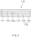
- FIG. 2 is a cross-sectional view taken along a line A-A' in FIG. 1 .
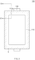
- FIG. 3 is a plan view illustrating the secondary battery, which is applied to the method for reinjecting an electrolyte according to an embodiment of the present invention.
- FIG. 4 is a cross-sectional view taken along a line B-B' in FIG. 3 .
- FIG. 5 is an enlarged cross-sectional view illustrating an area C in FIG. 4 .
- FIG. 6 is a cross-sectional view illustrating a concept of a reinjection process in the method for reinjecting an electrolyte according to an embodiment of the present invention.
- FIG. 7 is a cross-sectional view illustrating a concept of a sealing process in the method for reinjecting an electrolyte according to an embodiment of the present invention.
- FIGS. 6 and 7 are views illustrating respective examples of the concepts of the reinjection process and the sealing process by enlarging the area C in FIG. 4 .
- the method for reinjecting an electrolyte into a secondary battery is a method for reinjecting an electrolyte into a secondary battery 100 in which an electrode assembly 120 and an electrolyte are accommodated in a pouch 110.
- the pouch 110 comprises an aluminium sheet 113, in which a functional hole 113a is formed, and a polymer layer 111 and 116 stacked on the aluminium sheet 113.
- the method comprises a reinjection process of injecting an additional electrolyte into the pouch 110 through the functional hole 113a, and a sealing process of sealing the functional hole 113a after the reinjection process.
- the method for reinjecting an electrolyte into the secondary battery 100 is a method for reinjecting an electrolyte into the secondary battery 100 in which the electrode assembly 120, which is assembled by alternately stacking an electrode and a separator, and an electrolyte are accommodated in the pouch 110.
- the pouch 110 comprises the aluminium sheet 113, in which the functional hole 113a is formed, and the polymer layer 111 and 116 stacked on the aluminium sheet 113.
- a coating part 113b may be formed on an inner circumferential surface of the functional hole 113a in the aluminium sheet 113.
- the coating part 113b may comprise an insulating and chemically resistant material.
- the aluminum sheet 113 may be prevented from being oxidized due to contact of the electrolyte with the functional hole 113a portion, or electric current may be prevented from being conducted between the electrode assembly 120 and the aluminum sheet 113 through the functional hole 113a.
- the coating part 113b may comprise, for example, silicone, but the material of the coating part 113b is not necessarily limited thereto.
- an additional electrolyte is injected into the pouch 110 through the functional hole 113a.
- the functional hole 113a may be opened by forming a hole by means of a tool P in the portion, covering the functional hole 113a, of the polymer layer 111 and 116.
- the additional electrolyte may be injected through the functional hole 113a by piercing the portion, covering the functional hole 113a, of the polymer layer 111 and 116.
- the additional electrolyte may be injected through the functional hole 113a by penetrating an injection needle into the portion, covering the functional hole 113a, the polymer layer 111 and 116.
- the polymer layer 111 and 116 may comprise a first polymer layer 116 and a second polymer layer 111.
- the first polymer layer 116, the aluminium sheet 113, and the second polymer layer 111 may be stacked in the pouch 110 from the inside, in which the electrode assembly 120 is accommodated, to the outside.
- the first polymer layer 116 and the second polymer layer 111 may be formed on both surfaces of the aluminium sheet 113 to cover the functional hole 113a formed in the aluminium sheet 113.
- the first polymer layer 116 and the second polymer layer 111 may each comprise a polymer material.
- the first polymer layer 116 and the second polymer layer 111 which each comprise the polymer material permeable to gas such as CO and CO2, cover the functional hole 113a so that the internal gas may be discharged and the electrolyte may be prevented from being leaked through the functional hole 113a.
- the electrolyte may be injected into the pouch 110 through the functional hole 113a by opening portions, covering the functional hole 113a, of the first polymer layer 116 and the second polymer layer 111.
- a nylon layer 112 may be further stacked between the aluminium sheet 113 and the second polymer layer 111.
- the electrolyte may be injected into the pouch 110 through the functional hole 113a by opening portions, covering the functional hole 113a, of the first polymer layer 116, the nylon layer 112, and the second polymer layer 111.
- the first polymer layer 116 may be made of a polypropylene (PP) material
- the second polymer layer 111 may be made of a polyethylene terephthalate (PET) material.
- an inner layer, in which the electrode assembly 120 is accommodated may be made of a polypropylene (PP) material, and an outer layer, which faces the aluminium sheet 113, may be made of a polyphthalamide (PPa) material.
- the second polymer layer 111 may be made of a polyethylene terephthalate (PET) material.
- the functional hole 113a may be sealed after the reinjection process.
- the functional hole 113a may be sealed by sealing the portion, corresponding to the functional hole 113a, opened in the second polymer layer 111.
- the hole portion, corresponding to the functional hole 113a, opened in the second polymer layer 111 may be filled with a sealing material R to seal the functional hole 113a.
- the opened portion of the second polymer layer 111 may be sealed using a resin material R.
- the opened portion of the second polymer layer 111 may be sealed using the same material as the second polymer layer 111.
- the opened portion of the second polymer layer 111 is sealed using the same material as the second polymer layer 111, which comprises the polymer material permeable to gas such as CO and CO2, so that the internal gas may be discharged even though the injection portion is sealed through the sealing process after the electrolyte reinjection, and the electrolyte may be prevented from being leaked through the functional hole 113a.
- a secondary battery 100 capable of being reinjected with an electrolyte according to an embodiment of the present invention, comprises an electrode assembly 120, which is assembled by alternately stacking an electrode and a separator, and a pouch 110 in which the electrode assembly 120 is accommodated.
- the pouch 110 comprises an aluminium sheet 113 and a polymer layer 111 and 116 laminated with the aluminium sheet 113.
- a functional hole 113a is formed in the aluminium sheet 113.
- the secondary battery 100 capable of being reinjected with an electrolyte according to an embodiment of the present invention pertains to the secondary battery 100 to which the method for reinjecting an electrolyte according to the embodiment described above is applied.
- the content in common with the embodiment described above will be omitted or briefly provided, and the description of this embodiment will be focused on differences.
- the electrode assembly 120 is a power generation element chargeable and dischargeable, and is assembled by alternately stacking an electrode and a separator.
- the electrode may comprise a positive electrode and a negative electrode, and the positive electrode, the separator and the negative electrode may be alternately disposed.
- the electrode assembly 120 may further comprise an electrode lead 130 connected to an end of the electrode.
- the electrode assembly 120 may be electrically connected to an external device through the electrode lead 130.
- the pouch 110 may accommodate the electrode assembly 120.
- An accommodation part, in which the electrode assembly 120 is accommodated, may be formed inside the pouch 110.
- the pouch 110 may comprise the aluminium sheet 113, and the polymer layer 111 and 116 laminated with the aluminium sheet 113.
- the aluminium sheet 113 may form a layer in a sheet form of an aluminium material.
- the functional hole 113a may be formed in the aluminium sheet 113.
- the functional hole 113a may be formed in the aluminium sheet 113 to have a size of about 1-9 mm.
- the functional hole may be formed to penetrate the aluminium sheet 113 with respect to a stacked direction of the aluminium sheet 113 and the polymer layer 111 and 116.
- the functional hole 113a may be formed between the electrode assembly 120 in the pouch 110 and an outer circumferential surface of the pouch 110.
- the functional hole 113a may be formed in an aluminium sheet 113 portion at a side on which the electrode lead 130 is disposed.
- the polymer layer 111 and 116 may comprise a first polymer layer 116 and a second polymer layer 111.
- the first polymer layer 116 and the second polymer layer 111 may be formed on both surfaces of the aluminium sheet 113 to cover the functional hold 113a formed in the aluminium sheet 113.
- the first polymer layer 116 and the second polymer layer 111 may each comprise a polymer material. Accordingly, the first polymer layer 116 and the second polymer layer 111, which each comprise the polymer material permeable to gas such as CO and CO 2 , cover the functional hold 113a so that the internal gas may be discharged and the electrolyte may be prevented from being leaked through the functional hold 113a.
- a coating part 113b may be provided on an inner circumferential surface of the functional hole 113a in the aluminium sheet 113.
- the coating part 113b may be applied to cover the entirety of the inner circumferential surface of the functional hole 113a in the aluminium sheet 113.
- the coating part 113b may comprise an insulating and chemically resistant material. Accordingly, after a hole is formed in a portion, corresponding to the functional hole 113a, of the polymer layer 111 and 116 to reinject an electrolyte and then sealed, the aluminum sheet 113 may be prevented from being oxidized due to contact of the electrolyte with the functional hole 113a, or electric current may be prevented from being conducted between the electrode assembly and the aluminum sheet 113 through the functional hole 113a.
- the coating part 113b is formed along the inner circumferential surface of the functional hole 113a so that the electrolyte may be prevented from being in direct contact with the aluminum sheet 113 when the electrolyte enters the functional hold 113a in the aluminum sheet 113 through the hole portion of the first polymer layer 116 after holes are formed in portions, corresponding to the functional hold 113a, of the first polymer layer 116 and the second polymer layer 111 and then the hole portion of the second polymer layer 111 is sealed after the electrolyte reinjection.
- the coating part 113b is formed along the inner circumferential surface of the functional hole 113a so that the electrode assembly 120 may be prevented from being in direct contact with the aluminum sheet 113 through the hole portion of the first polymer layer 116.
- the coating part 113b may comprise, for example, silicone, but the material of the coating part 113b of the present invention is not necessarily limited thereto.
- first polymer layer 116, the aluminium sheet 113, and the second polymer layer 111 may be stacked in the pouch 110 from the inside, in which the electrode assembly 120 is accommodated, to the outside.
- first polymer layer 116, the aluminium sheet 113, and the second polymer layer 111 which each have a thickness of about 10-90 ⁇ m, may be stacked and adhered.
- a nylon layer 112 may be further stacked between the aluminium sheet 113 and the second polymer layer 111.
- the nylon layer 112 is made of a nylon material so that gas may pass therethrough.
- a corresponding hole may be formed in the nylon layer 112.
- the second polymer layer 111 may be made of a polyethylene terephthalate (PET) material.
- PET polyethylene terephthalate
- the first polymer layer 116 may be made of a polypropylene (PP) material.
- PP polypropylene
- an inner layer 115 in which the electrode assembly 120 is accommodated, may be made of a polypropylene (PP) material, and an outer layer 114, which faces the aluminium sheet 113, may be made of a polyphthalamide (PPa) material.
- PP polypropylene
- PPa polyphthalamide
- a sealing part S may be formed on the outer circumferential surface of the pouch 110 to seal the inside of the pouch 110.
- the sealing part S may be formed through thermal fusion of the outer circumferential surface of the pouch 110 in a third direction or a fourth direction.
Landscapes
- Chemical & Material Sciences (AREA)
- Chemical Kinetics & Catalysis (AREA)
- Electrochemistry (AREA)
- General Chemical & Material Sciences (AREA)
- Inorganic Chemistry (AREA)
- Sealing Battery Cases Or Jackets (AREA)
- Secondary Cells (AREA)
- Filling, Topping-Up Batteries (AREA)
Applications Claiming Priority (2)
| Application Number | Priority Date | Filing Date | Title |
|---|---|---|---|
| KR1020200182659A KR102945582B1 (ko) | 2020-12-23 | 전해액 재주액 방법 및 전해액 재주액이 가능한 이차전지 | |
| PCT/KR2021/019597 WO2022139450A1 (ko) | 2020-12-23 | 2021-12-22 | 전해액 재주액 방법 및 전해액 재주액이 가능한 이차전지 |
Publications (2)
| Publication Number | Publication Date |
|---|---|
| EP4228084A1 true EP4228084A1 (de) | 2023-08-16 |
| EP4228084A4 EP4228084A4 (de) | 2024-12-18 |
Family
ID=82158522
Family Applications (1)
| Application Number | Title | Priority Date | Filing Date |
|---|---|---|---|
| EP21911517.7A Pending EP4228084A4 (de) | 2020-12-23 | 2021-12-22 | Verfahren zur neuinjektion eines elektrolyten und sekundärbatterie zur ermöglichung der elektrolytneuinjektion |
Country Status (5)
| Country | Link |
|---|---|
| US (1) | US20240030571A1 (de) |
| EP (1) | EP4228084A4 (de) |
| JP (1) | JP2023550109A (de) |
| CN (1) | CN116472644A (de) |
| WO (1) | WO2022139450A1 (de) |
Families Citing this family (2)
| Publication number | Priority date | Publication date | Assignee | Title |
|---|---|---|---|---|
| WO2024065786A1 (zh) * | 2022-09-30 | 2024-04-04 | 宁德时代新能源科技股份有限公司 | 包装壳、电池单体、电池模组、电池及用电装置 |
| JP7661961B2 (ja) | 2022-12-20 | 2025-04-15 | トヨタ自動車株式会社 | 積層電池の製造方法および積層電池 |
Family Cites Families (11)
| Publication number | Priority date | Publication date | Assignee | Title |
|---|---|---|---|---|
| WO2011024798A1 (ja) * | 2009-08-27 | 2011-03-03 | 大日精化工業株式会社 | 水系の炭素フィラー分散塗工液、導電性付与材料、蓄電装置用電極板、蓄電装置用電極板の製造方法及び蓄電装置 |
| JP5703996B2 (ja) * | 2010-09-21 | 2015-04-22 | 日産自動車株式会社 | 電池容量回復装置及び電池容量回復方法 |
| KR101859499B1 (ko) * | 2010-11-30 | 2018-05-21 | (주)아모레퍼시픽 | 세포외기질을 모사한 지방유래 줄기세포의 줄기세포성 증진용 조성물 |
| KR101543494B1 (ko) * | 2012-05-31 | 2015-08-10 | 주식회사 엘지화학 | 전해액 주입구 및/또는 가스 배출구를 구비하는 파우치형 전지 |
| KR101528001B1 (ko) | 2012-06-22 | 2015-06-10 | 주식회사 엘지화학 | 이차전지용 전극조립체, 그 제조방법 및 이를 이용한 이차전지 |
| KR101651141B1 (ko) * | 2013-09-03 | 2016-08-25 | 주식회사 엘지화학 | 이차전지용 파우치 외장재 및 이를 포함하는 파우치형 이차전지 |
| KR101852662B1 (ko) * | 2015-01-22 | 2018-04-26 | 주식회사 엘지화학 | 이차전지용 파우치 외장재 및 이를 포함하는 파우치형 이차전지 |
| US20180351154A1 (en) * | 2016-01-29 | 2018-12-06 | Lg Chem, Ltd. | Battery cell and method for manufacturing battery cell |
| KR20160038883A (ko) * | 2016-03-03 | 2016-04-07 | 주식회사 한스크리에이티브 | Lbs 및 rcs 융합 기반의 스마트 쇼핑 시스템 |
| KR102135805B1 (ko) * | 2016-03-31 | 2020-07-20 | 주식회사 엘지화학 | 파우치의 주입부 실링 장치 및 방법 |
| KR102031276B1 (ko) * | 2016-08-26 | 2019-10-11 | 주식회사 엘지화학 | 이차전지 및 이차전지의 전해액 보충 방법 |
-
2021
- 2021-12-22 CN CN202180076287.4A patent/CN116472644A/zh active Pending
- 2021-12-22 US US18/254,680 patent/US20240030571A1/en active Pending
- 2021-12-22 WO PCT/KR2021/019597 patent/WO2022139450A1/ko not_active Ceased
- 2021-12-22 EP EP21911517.7A patent/EP4228084A4/de active Pending
- 2021-12-22 JP JP2023530049A patent/JP2023550109A/ja active Pending
Also Published As
| Publication number | Publication date |
|---|---|
| US20240030571A1 (en) | 2024-01-25 |
| EP4228084A4 (de) | 2024-12-18 |
| JP2023550109A (ja) | 2023-11-30 |
| WO2022139450A1 (ko) | 2022-06-30 |
| CN116472644A (zh) | 2023-07-21 |
| KR20220091295A (ko) | 2022-06-30 |
Similar Documents
| Publication | Publication Date | Title |
|---|---|---|
| JP2010086753A (ja) | 蓄電デバイス | |
| US11362383B2 (en) | Secondary battery | |
| EP4228084A1 (de) | Verfahren zur neuinjektion eines elektrolyten und sekundärbatterie zur ermöglichung der elektrolytneuinjektion | |
| EP4203161B1 (de) | Batteriezelle und batteriemodul damit | |
| KR20220126256A (ko) | 전지셀 및 이를 제조하는 전지셀 제조 장치 | |
| EP4145598B1 (de) | Batteriezelle und batteriemodul damit | |
| EP3392933B1 (de) | Sekundärbatterie und verfahren zum ergänzen des elektrolyten der sekundärbatterie | |
| CN115461916B (zh) | 电池电芯和包括该电池电芯的电池模块 | |
| EP3654412B1 (de) | Sekundärbatterie | |
| KR20140015201A (ko) | 파우치 외장재 실링용 실링툴 및 파우치형 이차전지의 제조방법 | |
| EP4224607A1 (de) | Beutel, sekundärbatterie damit und verfahren zur herstellung davon | |
| KR101357311B1 (ko) | 파우치형 이차전지 및 그의 제조방법 | |
| KR20180136751A (ko) | 이차전지 | |
| EP4303976A1 (de) | Sekundärbatterie, batteriepack und vorrichtung damit | |
| KR102945582B1 (ko) | 전해액 재주액 방법 및 전해액 재주액이 가능한 이차전지 | |
| KR101379691B1 (ko) | 전해액 재충전이 가능한 이차 전지 | |
| KR100303842B1 (ko) | 리튬 이온 폴리머 전지 | |
| KR102158146B1 (ko) | 이차전지 및 그 제조방법 | |
| KR20210011590A (ko) | 전극조립체 및 이를 포함하는 리튬이차전지 | |
| JP7671855B2 (ja) | 二次電池 | |
| KR100300427B1 (ko) | 이차 전지와 이의 제조 방법 | |
| KR20250170344A (ko) | 파우치형 전지 셀 및 이의 제조방법 | |
| KR20230126383A (ko) | 젤리롤 전극 조립체 및 이를 포함하는 이차전지 | |
| KR20250063254A (ko) | 이차 전지 | |
| KR20220090279A (ko) | 배터리 셀, 배터리 셀의 전해액 주입 장치, 및 이를 이용한 전해액 주입 방법 |
Legal Events
| Date | Code | Title | Description |
|---|---|---|---|
| STAA | Information on the status of an ep patent application or granted ep patent |
Free format text: STATUS: THE INTERNATIONAL PUBLICATION HAS BEEN MADE |
|
| PUAI | Public reference made under article 153(3) epc to a published international application that has entered the european phase |
Free format text: ORIGINAL CODE: 0009012 |
|
| STAA | Information on the status of an ep patent application or granted ep patent |
Free format text: STATUS: REQUEST FOR EXAMINATION WAS MADE |
|
| 17P | Request for examination filed |
Effective date: 20230511 |
|
| AK | Designated contracting states |
Kind code of ref document: A1 Designated state(s): AL AT BE BG CH CY CZ DE DK EE ES FI FR GB GR HR HU IE IS IT LI LT LU LV MC MK MT NL NO PL PT RO RS SE SI SK SM TR |
|
| DAV | Request for validation of the european patent (deleted) | ||
| DAX | Request for extension of the european patent (deleted) | ||
| A4 | Supplementary search report drawn up and despatched |
Effective date: 20241115 |
|
| RIC1 | Information provided on ipc code assigned before grant |
Ipc: H01M 50/30 20210101ALI20241111BHEP Ipc: H01M 50/342 20210101ALI20241111BHEP Ipc: H01M 50/105 20210101ALI20241111BHEP Ipc: H01M 50/126 20210101ALI20241111BHEP Ipc: H01M 50/664 20210101ALI20241111BHEP Ipc: H01M 50/609 20210101AFI20241111BHEP |
|
| STAA | Information on the status of an ep patent application or granted ep patent |
Free format text: STATUS: EXAMINATION IS IN PROGRESS |
|
| 17Q | First examination report despatched |
Effective date: 20250723 |
|
| GRAP | Despatch of communication of intention to grant a patent |
Free format text: ORIGINAL CODE: EPIDOSNIGR1 |
|
| STAA | Information on the status of an ep patent application or granted ep patent |
Free format text: STATUS: GRANT OF PATENT IS INTENDED |
|
| INTG | Intention to grant announced |
Effective date: 20260105 |
|
| GRAS | Grant fee paid |
Free format text: ORIGINAL CODE: EPIDOSNIGR3 |
|
| P01 | Opt-out of the competence of the unified patent court (upc) registered |
Free format text: CASE NUMBER: UPC_APP_0003938_4228084/2026 Effective date: 20260203 |
|
| GRAA | (expected) grant |
Free format text: ORIGINAL CODE: 0009210 |
|
| STAA | Information on the status of an ep patent application or granted ep patent |
Free format text: STATUS: THE PATENT HAS BEEN GRANTED |