EP3392933B1 - Sekundärbatterie und verfahren zum ergänzen des elektrolyten der sekundärbatterie - Google Patents
Sekundärbatterie und verfahren zum ergänzen des elektrolyten der sekundärbatterie Download PDFInfo
- Publication number
- EP3392933B1 EP3392933B1 EP17843829.7A EP17843829A EP3392933B1 EP 3392933 B1 EP3392933 B1 EP 3392933B1 EP 17843829 A EP17843829 A EP 17843829A EP 3392933 B1 EP3392933 B1 EP 3392933B1
- Authority
- EP
- European Patent Office
- Prior art keywords
- electrolyte
- sealing member
- battery case
- secondary battery
- additionally injecting
- Prior art date
- Legal status (The legal status is an assumption and is not a legal conclusion. Google has not performed a legal analysis and makes no representation as to the accuracy of the status listed.)
- Active
Links
Images


Classifications
-
- H—ELECTRICITY
- H01—ELECTRIC ELEMENTS
- H01M—PROCESSES OR MEANS, e.g. BATTERIES, FOR THE DIRECT CONVERSION OF CHEMICAL ENERGY INTO ELECTRICAL ENERGY
- H01M50/00—Constructional details or processes of manufacture of the non-active parts of electrochemical cells other than fuel cells, e.g. hybrid cells
- H01M50/60—Arrangements or processes for filling or topping-up with liquids; Arrangements or processes for draining liquids from casings
-
- H—ELECTRICITY
- H01—ELECTRIC ELEMENTS
- H01M—PROCESSES OR MEANS, e.g. BATTERIES, FOR THE DIRECT CONVERSION OF CHEMICAL ENERGY INTO ELECTRICAL ENERGY
- H01M10/00—Secondary cells; Manufacture thereof
- H01M10/60—Heating or cooling; Temperature control
- H01M10/65—Means for temperature control structurally associated with the cells
- H01M10/655—Solid structures for heat exchange or heat conduction
- H01M10/6551—Surfaces specially adapted for heat dissipation or radiation, e.g. fins or coatings
-
- H—ELECTRICITY
- H01—ELECTRIC ELEMENTS
- H01M—PROCESSES OR MEANS, e.g. BATTERIES, FOR THE DIRECT CONVERSION OF CHEMICAL ENERGY INTO ELECTRICAL ENERGY
- H01M10/00—Secondary cells; Manufacture thereof
- H01M10/42—Methods or arrangements for servicing or maintenance of secondary cells or secondary half-cells
- H01M10/4214—Arrangements for moving electrodes or electrolyte
-
- H—ELECTRICITY
- H01—ELECTRIC ELEMENTS
- H01M—PROCESSES OR MEANS, e.g. BATTERIES, FOR THE DIRECT CONVERSION OF CHEMICAL ENERGY INTO ELECTRICAL ENERGY
- H01M50/00—Constructional details or processes of manufacture of the non-active parts of electrochemical cells other than fuel cells, e.g. hybrid cells
- H01M50/10—Primary casings; Jackets or wrappings
- H01M50/102—Primary casings; Jackets or wrappings characterised by their shape or physical structure
- H01M50/105—Pouches or flexible bags
-
- H—ELECTRICITY
- H01—ELECTRIC ELEMENTS
- H01M—PROCESSES OR MEANS, e.g. BATTERIES, FOR THE DIRECT CONVERSION OF CHEMICAL ENERGY INTO ELECTRICAL ENERGY
- H01M50/00—Constructional details or processes of manufacture of the non-active parts of electrochemical cells other than fuel cells, e.g. hybrid cells
- H01M50/10—Primary casings; Jackets or wrappings
- H01M50/183—Sealing members
- H01M50/186—Sealing members characterised by the disposition of the sealing members
-
- H—ELECTRICITY
- H01—ELECTRIC ELEMENTS
- H01M—PROCESSES OR MEANS, e.g. BATTERIES, FOR THE DIRECT CONVERSION OF CHEMICAL ENERGY INTO ELECTRICAL ENERGY
- H01M50/00—Constructional details or processes of manufacture of the non-active parts of electrochemical cells other than fuel cells, e.g. hybrid cells
- H01M50/10—Primary casings; Jackets or wrappings
- H01M50/183—Sealing members
- H01M50/19—Sealing members characterised by the material
- H01M50/193—Organic material
-
- H—ELECTRICITY
- H01—ELECTRIC ELEMENTS
- H01M—PROCESSES OR MEANS, e.g. BATTERIES, FOR THE DIRECT CONVERSION OF CHEMICAL ENERGY INTO ELECTRICAL ENERGY
- H01M50/00—Constructional details or processes of manufacture of the non-active parts of electrochemical cells other than fuel cells, e.g. hybrid cells
- H01M50/60—Arrangements or processes for filling or topping-up with liquids; Arrangements or processes for draining liquids from casings
- H01M50/609—Arrangements or processes for filling with liquid, e.g. electrolytes
- H01M50/627—Filling ports
- H01M50/636—Closing or sealing filling ports, e.g. using lids
-
- Y—GENERAL TAGGING OF NEW TECHNOLOGICAL DEVELOPMENTS; GENERAL TAGGING OF CROSS-SECTIONAL TECHNOLOGIES SPANNING OVER SEVERAL SECTIONS OF THE IPC; TECHNICAL SUBJECTS COVERED BY FORMER USPC CROSS-REFERENCE ART COLLECTIONS [XRACs] AND DIGESTS
- Y02—TECHNOLOGIES OR APPLICATIONS FOR MITIGATION OR ADAPTATION AGAINST CLIMATE CHANGE
- Y02E—REDUCTION OF GREENHOUSE GAS [GHG] EMISSIONS, RELATED TO ENERGY GENERATION, TRANSMISSION OR DISTRIBUTION
- Y02E60/00—Enabling technologies; Technologies with a potential or indirect contribution to GHG emissions mitigation
- Y02E60/10—Energy storage using batteries
Definitions
- the present invention relates to a secondary battery and a method for supplementing an electrolyte of the secondary battery.
- Secondary batteries are rechargeable unlike primarily batteries, and also, the possibility of compact size and high capacity is high. Thus, recently, many studies on secondary batteries are being carried out. As technology development and demands for mobile devices increase, the demands for secondary batteries as energy sources are rapidly increasing.
- Secondary batteries are classified into coin type batteries, cylindrical type batteries, prismatic type batteries, and pouch type batteries according to a shape of a battery case.
- an electrode assembly mounted in a battery case is a chargeable and dischargeable power generating device having a structure in which an electrode and a separator are stacked.
- the electrode assembly may be approximately classified into a jelly-roll type electrode assembly in which a separator is interposed between a positive electrode and a negative electrode, each of which is provided as the form of a sheet coated with an active material, and then, the positive electrode, the separator, and the negative electrode are wound, a stacked type electrode assembly in which a plurality of positive and negative electrodes with a separator therebetween are sequentially stacked, and a stack/folding type electrode assembly in which stacked type unit cells are wound together with a separation film having a long length.
- the pouch-type battery in which a stack/folding type electrode assembly is built in a pouch-type battery case provided as an aluminum lamination sheet is attracting much attention due to its low manufacturing cost, small weight, easy shape deformation, and the like, and thus, its usage is gradually increasing.
- a patent document KR 2012 0069297 discloses a secondary battery having a sealing member for additionally injecting an electrolyte.
- One aspect of the present invention is to provide a secondary battery in which an electrolyte is capable of being additionally injected and which is resealed after the injection of the electrolyte .
- the pouch-type secondary battery comprises a battery case comprising an accommodation part accommodating an electrode and an electrolyte therein and a sealing member for additionally injecting the electrolyte, which is disposed on a portion of the battery case to additionally inject the electrolyte into the accommodation part of the battery case and seals an injection portion, wherein the sealing member for additionally injecting the electrolyte passes through the inside and outside of the battery case so that the electrolyte is injected through a penetrated portion of the sealing member.
- a method for supplementing an electrolyte of a secondary battery may comprise an injection preparation process of allowing an injection needle to pass through a sealing member for additionally injecting the electrolyte, which passes through the inside and outside of a battery case and is formed on a portion of the battery case so that the injection needle passes through a penetrated portion of the sealing member to inject the electrolyte, an injection process of additionally injecting the electrolyte into an accommodation part of the battery case, in which an electrode assembly and the electrolyte are accommodated, through the injection needle, and a sealing process of sealing the portion of the sealing member, through which the injection needle passes, after the injection needle is removed from the sealing member for additionally injecting the electrolyte.
- the sealing member for additionally injecting the electrolyte is disposed on a portion of the battery case to additionally inject the electrolyte into the battery. After the electrolyte is injected, the sealing member may be resealed.
- the sealing member for additionally injecting the electrolyte may be made of the thermoplastic member.
- the sealing member when heat is applied, the sealing member may have fluidity so that the needle for injecting the electrolyte easily passes through the sealing member.
- the portion of the sealing member, through which the needle passes, may be easily sealed.
- the thermoplastic member may be made of the silicone sealant.
- the sealing member for additionally injecting the electrolyte may be provided as the highly contractive member to seal the penetrated portion by the self-contacting force thereof when the injection needle is removed, thereby sealing the sealing member for additionally injecting the electrolyte without performing separate sealing processing.
- FIGS. 5 and 10 A secondary battery according to the present invention is shown in FIGS. 5 and 10 .
- the batteries shown in the remaining figures do not fall within the scope of the appended claims.
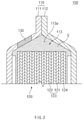
- FIG. 1 is a perspective view of a secondary battery according to a first embodiment of the present disclosure
- FIG. 2 is a cross-sectional view illustrating a main part of the secondary battery according to the first embodiment of the present disclosure.
- a secondary battery 100 according to a first embodiment of the present disclosure comprises a battery case 110 accommodating an electrode assembly 120 and an electrolyte G and a sealing member 130 for additionally injecting the electrolyte G, which is disposed on a portion of the battery case 110.
- the battery case 110 comprises a first case 111 and a second case 112 and also comprises an accommodation part 113 accommodating the electrode assembly 120 and the electrolyte G therein.
- the battery case 110 has a space part 113a in which the electrode assembly 120 is not disposed in the accommodation part 120.
- the space part 113a is formed in the battery case 110 so that the sealing member 130 for additionally injecting the electrolyte G is adjacent to the space part 113a.
- the electrode assembly 120 may be a chargeable and dischargeable power generation element and have a structure in which an electrode 123 and a separator 124 are combined and alternately stacked. Also, the electrode assembly 120 may comprise an electrode lead 125 electrically connected to the electrode 123.
- the electrode 123 may comprise a positive electrode 121 and a negative electrode 122.
- the electrode assembly 120 may have a structure in which the positive electrode 121/the separator 124/the negative electrode 122 are alternately stacked.
- the separator 124 is made of an insulation material to electrically insulate the positive electrode 121 from the negative electrode 122.
- the separator 124 may be made of, for example, a polyolefin-based resin film such as polyethylene or polypropylene having micropores.
- the sealing member 130 for additionally injecting the electrolyte G may be disposed on a portion of the battery case 110 so that an injection portion of the battery case 110 is sealed after the electrolyte G is additionally injected into the accommodation part 113 of the battery case 110.
- the sealing member 130 for additionally injecting the electrolyte G may be made of a thermoplastic member.
- the sealing member when heat is applied, the sealing member may have fluidity so that an injection needle easily passes through the sealing member.
- the injection portion having a through-hole, through which the injection needle passes may be easily sealed.
- the thermoplastic member may be made of, for example, a silicone sealant.
- the fluidity may be more improved so that the injection need more easily passes through the sealing member 130.
- the thermal treating process is repeatedly performed, the material damage of the sealing member 130 for additionally injecting the electrolyte G may be minimized.
- the injection needle is removed after heat is applied to allow the injection needle to pass, and then heat is applied again, the injection portion may return to its original shape. That is, when the heat is applied to the penetrated portion of the sealing member 130 for additionally injecting the electrolyte G while the injection is performed, the penetrated portion may be filled to completely seal the injection portion.
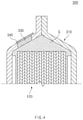
- FIG. 3 is a cross-sectional view illustrating a main part of a secondary battery according to a second embodiment of the present disclosure.
- a secondary battery 200 further comprises a protrusion end 214 on a battery case 210 to support the sealing member 230 for additionally injecting the electrolyte G, thereby preventing the sealing member 230 from being separated from the battery case 210.
- the protrusion end 214 protrudes from each of inner and outer surfaces of the battery case 210 in a direction of the sealing member 230 for additionally injecting the electrolyte G to support the sealing member 230 for additionally injecting the electrolyte G, thereby preventing the sealing member 230 from being separated toward the inside and outside of the battery case 210.
- the protrusion end 214 may protrude to be disposed along an edge of each of upper and lower end of the sealing member 230 for additionally injecting the electrolyte G.
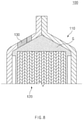
- FIG. 4 is a cross-sectional view illustrating a main part of a secondary battery according to a third embodiment of the present disclosure.
- a secondary battery 300 according to a third embodiment of the present disclosure comprises a battery case 310 accommodating an electrode assembly 120 and an electrolyte G, a sealing member 330 for additionally injecting the electrolyte G, which is disposed on a portion of the battery case 310, and a sealing tape 340 attached to the sealing member 330 for additionally injecting the electrolyte G.
- the secondary battery 300 according to the third embodiment of the present disclosure is different from the secondary battery 100 according to the first embodiment and the secondary battery 200 according to the second embodiment in that the sealing member 330 for additionally injecting the electrolyte G is provided as a highly contractive member to allow the sealing tape 340 to the sealing member 330 for additionally injecting the electrolyte G.
- the sealing member 330 for additionally injecting the electrolyte G is provided as a highly contractive member to allow the sealing tape 340 to the sealing member 330 for additionally injecting the electrolyte G.
- the sealing member 330 for additionally injecting the electrolyte G may be provided as the highly contractive member, and thus an injection portion may be sealed by self-contracting force thereof.
- the highly contractive member may be made of, for example, silicone rubber.
- the sealing tape 340 may be attached to an outer surface of the sealing member 330 for additionally injecting the electrolyte G to additionally seal the injection portion.
- the sealing tape 340 may be provided as, for example, Kapton tape.
- the Kapton tape may be excellent in heat resistance, cold resistance, chemical resistance, insulation, withstand voltage, and the like to improve sealability, thereby protecting the sealing member 330 for additionally injecting the electrolyte G against various environments.
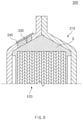
- FIG. 5 is a cross-sectional view illustrating a main part of a secondary battery according to a fourth embodiment of the present invention.
- the sealing member 430 for additionally injecting the electrolyte G may comprise a thermoplastic member, a highly contractive member, a heat dissipation member 433.
- an outer part 431 of the sealing member 430 with respect to an accommodation part of the battery case 410 is provided as the thermoplastic member to seal the injection portion by applying heat.
- the inner part 432 of the sealing member 430 is provided as the highly contractive member to seal the injection portion by self-contracting force thereof.
- the thermoplastic member is made of a silicone sealant
- the highly contractive member is made of silicone rubber.
- the sealing member 430 for additionally injecting the electrolyte G further comprises the heat dissipation member 433 disposed between an outer part 431 and an inner part 432 to block heat transfer between the outer part 431 and the inner part 432.
- the heat dissipation member 433 may be made of a Kapton material.
- the heat dissipation member 433 may be provided as, for example, a Kapton tape.
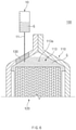
- FIG. 6 is a view illustrating an example of an injection preparation process and an injection process in a method for supplementing an electrolyte of a secondary battery according to an embodiment of the present disclosure
- FIG. 7 is a view illustrating an example of a state in which the injection needle is removed after the electrolyte is injected in the method for supplementing the electrolyte according to an embodiment of the present disclosure
- FIG. 8 is a view illustrating an example of a sealing process in the method for supplementing the electrolyte according to an embodiment of the present disclosure.
- an injection needle 11 passes through a sealing member 130 for additionally injecting the electrolyte G, which passes through the inside and outside of a battery case 110 and is formed on a portion of a battery case 110 so that the injection needle 11 passes through a penetrated portion of the sealing member to inject the electrolyte G.
- the injection needle 11 may pass through the sealing member 130 for additionally injecting the electrolyte G so that the electrolyte G is additionally injected into a space part 113a, in which the electrode assembly 120 is not disposed in an accommodation part 113 of the battery case 110, through the sealing member 130 for additionally injecting the electrolyte G.
- heat may be applied to the sealing member 130 for additionally injecting the electrolyte G, which is provided as a thermoplastic member, so that the injection needle 11 easily passes through the sealing member 130.
- the sealing member 130 may change in fluidity so that the injection needle 11 passes therethrough.
- the electrolyte G may be accommodated in the injection needle 10 and then be additionally injected into the accommodation part 113 of the battery case 110 through the injection needle 11 passing through the sealing member 130 for additionally injecting the electrolyte G.
- a through-hole H formed by the penetration of the injection needle 11 may be sealed.
- heat is applied to the sealing member 130 for additionally injecting the electrolyte G, which is provided as, for example, the thermoplastic member to seal the portion of the sealing member 130, through which the injection needle passes.
- the sealing member 130 for additionally injecting the electrolyte G, which is made of a silicone sealant, to seal the penetrated portion.
- FIG. 9 is a view illustrating another example of the sealing process in the method for supplementing the electrolyte according to an embodiment of the present disclosure.
- a sealing tape 340 may be attached to an outer surface of the sealing member 330 for additionally injecting the electrolyte G to additionally seal the injection portion that is sealed by the self-contracting force of the highly contractive member.
- the sealing tape 340 may be provided as a Kapton tape.
- the sealing tape 340 may be attached before the injection preparation process.
- a portion or the whole of the sealing tape 340 may be separated from the sealing member 330 for additionally injecting the electrolyte G, and then, the injection needle may pass through the sealing member 330 for additionally injecting the electrolyte G.
- the injection needle may be removed from the sealing member 330 for additionally injecting the electrolyte G, and then, a portion of the sealing tape 340, which is separated from the sealing member 330 for additionally injecting the electrolyte G, may be attached again to the sealing member 330 for additionally injecting the electrolyte G to additionally seal the sealing member 330.
- FIG. 10 is a view illustrating further another example of the sealing process in the method for supplementing the electrolyte according to an embodiment of the present disclosure.
- heat transfer between the outer part 431 and the inner part 432 may be blocked by a heat dissipation member 433 disposed between the outer part 431 and the inner part 432 of the sealing member 430 for additionally injecting the electrolyte G.
- the heat dissipation member 433 may be provided as, for example, a Kapton tape.
Landscapes
- Chemical & Material Sciences (AREA)
- Chemical Kinetics & Catalysis (AREA)
- Electrochemistry (AREA)
- General Chemical & Material Sciences (AREA)
- Engineering & Computer Science (AREA)
- Manufacturing & Machinery (AREA)
- Secondary Cells (AREA)
- Filling, Topping-Up Batteries (AREA)
- Sealing Battery Cases Or Jackets (AREA)
Claims (3)
- Sekundärbatterie vom Beuteltyp, umfassend:ein Batteriegehäuse (410), umfassend einen Aufnahmeteil, welcher eine Elektrode und einen Elektrolyten (G) darin aufnimmt;
undein Abdichtelement (430) zum zusätzlichen Injizieren des Elektrolyten (G), welches an einem Abschnitt des Batteriegehäuses (410) angeordnet ist, um den Elektrolyten (G) in den Aufnahmeteil des Batteriegehäuses (410) zusätzlich zu injizieren, und einen Injektionsabschnitt abdichtet,wobei, in dem Abdichtelement (430) zum zusätzlichen Injizieren des Elektrolyten (G), ein in Bezug auf den Aufnahmeteil des Batteriegehäuses (410) äußerer Teil (431) des Abdichtelements (430) aus einem Silikondichtmittel hergestellt ist, um den Injektionsabschnitt durch Anwenden von Wärme abzudichten, und ein innerer Teil (432) des Abdichtelements (430) aus Silikonkautschuk hergestellt ist, um den Injektionsabschnitt durch eine Selbst-Kontraktionskraft davon abzudichten,wobei das Abdichtelement (430) zum zusätzlichen Injizieren des Elektrolyten (G) ferner ein Wärmeableitungselement (433) umfasst, welches zwischen dem äußeren Teil und dem inneren Teil angeordnet ist, um eine Wärmeübertragung zwischen dem äußeren Teil (431) und dem inneren Teil (432) zu blockieren, undwobei das Abdichtelement (430) zum zusätzlichen Injizieren des Elektrolyten (G) durch das Innere und das Äußere des Batteriegehäuses (410) verläuft, so dass der Elektrolyt (G) durch einen durchdrungenen Abschnitt des Abdichtelements (430) injiziert wird. - Sekundärbatterie vom Beuteltyp nach Anspruch 1, wobei das Batteriegehäuse (410) ferner ein Vorsprungsende umfasst, welches von jeden aus inneren und äußeren Flächen des Batteriegehäuses (410) in einer Richtung des Abdichtelements (430) zum zusätzlichen Injizieren des Elektrolyten vorsteht, um das Abdichtelement (430) zum zusätzlichen Injizieren des Elektrolyten zu haltern, wodurch verhindert wird, dass das Abdichtelement (430) von dem Batteriegehäuse (410) getrennt wird.
- Sekundärbatterie vom Beuteltyp nach Anspruch 1, wobei das Wärmeableitungselement (433) aus einem Kapton-Material hergestellt ist.
Priority Applications (1)
| Application Number | Priority Date | Filing Date | Title |
|---|---|---|---|
| PL17843829T PL3392933T3 (pl) | 2016-08-26 | 2017-07-26 | Bateria akumulatorowa i sposób uzupełniania elektrolitu w baterii akumulatorowej |
Applications Claiming Priority (2)
| Application Number | Priority Date | Filing Date | Title |
|---|---|---|---|
| KR1020160109485A KR102031276B1 (ko) | 2016-08-26 | 2016-08-26 | 이차전지 및 이차전지의 전해액 보충 방법 |
| PCT/KR2017/008069 WO2018038409A1 (ko) | 2016-08-26 | 2017-07-26 | 이차전지 및 이차전지의 전해액 보충 방법 |
Publications (3)
| Publication Number | Publication Date |
|---|---|
| EP3392933A1 EP3392933A1 (de) | 2018-10-24 |
| EP3392933A4 EP3392933A4 (de) | 2018-11-14 |
| EP3392933B1 true EP3392933B1 (de) | 2022-03-16 |
Family
ID=61245083
Family Applications (1)
| Application Number | Title | Priority Date | Filing Date |
|---|---|---|---|
| EP17843829.7A Active EP3392933B1 (de) | 2016-08-26 | 2017-07-26 | Sekundärbatterie und verfahren zum ergänzen des elektrolyten der sekundärbatterie |
Country Status (7)
| Country | Link |
|---|---|
| US (1) | US10944084B2 (de) |
| EP (1) | EP3392933B1 (de) |
| JP (1) | JP6830106B2 (de) |
| KR (1) | KR102031276B1 (de) |
| CN (1) | CN108604662B (de) |
| PL (1) | PL3392933T3 (de) |
| WO (1) | WO2018038409A1 (de) |
Families Citing this family (5)
| Publication number | Priority date | Publication date | Assignee | Title |
|---|---|---|---|---|
| KR20210079084A (ko) * | 2019-12-19 | 2021-06-29 | 주식회사 엘지에너지솔루션 | 이차전지 및 그의 제조방법 |
| US12334601B2 (en) | 2020-12-22 | 2025-06-17 | Sk On Co., Ltd. | Battery cell, electrolyte injection apparatus for battery cell, and electrolyte injection method using the same |
| CN116472644A (zh) * | 2020-12-23 | 2023-07-21 | 株式会社 Lg新能源 | 再注入电解质的方法以及能够再注入电解质的二次电池 |
| KR20230076463A (ko) | 2021-11-24 | 2023-05-31 | 주식회사 엘지에너지솔루션 | 전해액 추가 주액이 가능한 리튬 이차전지 |
| JP7661961B2 (ja) * | 2022-12-20 | 2025-04-15 | トヨタ自動車株式会社 | 積層電池の製造方法および積層電池 |
Family Cites Families (28)
| Publication number | Priority date | Publication date | Assignee | Title |
|---|---|---|---|---|
| JPH09199108A (ja) * | 1996-01-17 | 1997-07-31 | Toshiba Corp | 電池製造における電解液注入装置および電解液注入方法 |
| JP4015826B2 (ja) * | 2001-06-19 | 2007-11-28 | 株式会社東芝 | 非水電解質空気電池 |
| EP1289035A2 (de) * | 2001-08-29 | 2003-03-05 | Matsushita Electric Industrial Co., Ltd. | Verbundelektrode für die Reduktion von Sauerstoff |
| US7368659B2 (en) * | 2002-11-26 | 2008-05-06 | General Electric Company | Electrodes mitigating effects of defects in organic electronic devices |
| KR100779002B1 (ko) * | 2005-12-23 | 2007-11-22 | 삼성에스디아이 주식회사 | 리튬 이차전지 및 그 제조방법 |
| JP2008041548A (ja) | 2006-08-09 | 2008-02-21 | Sanyo Electric Co Ltd | 非水電解液二次電池 |
| US20080070101A1 (en) | 2006-09-14 | 2008-03-20 | Joseph Barrella | Foil cell fill port |
| FR2936653B1 (fr) | 2008-09-30 | 2011-02-11 | Commissariat Energie Atomique | Accumulateur a electrolyte liquide et procede de remplissage |
| CN101533927B (zh) | 2009-03-17 | 2010-09-29 | 林道勇 | 一种锂离子电池的制造方法 |
| KR101174956B1 (ko) * | 2009-08-26 | 2012-08-17 | 에스비리모티브 주식회사 | 이차전지 |
| US20110091765A1 (en) | 2009-10-19 | 2011-04-21 | Samsung Sdi Co., Ltd. | Secondary battery including sealing structure for electrolyte injection hole and method of manufacturing the secondary battery |
| CN102044715A (zh) * | 2009-10-22 | 2011-05-04 | 上海集浪能源科技有限公司 | 锂电池防爆装置 |
| US8752573B2 (en) | 2009-11-06 | 2014-06-17 | Sharp Kabushiki Kaisha | Non-aqueous electrolyte secondary battery with filling function, and non-aqueous electrolyte secondary battery and non-aqueous electrolyte filling device used therefor |
| KR101201808B1 (ko) | 2010-06-03 | 2012-11-15 | 삼성에스디아이 주식회사 | 이차 전지 및 이차 전지의 전해액 주입 방법 |
| KR101271254B1 (ko) * | 2010-10-08 | 2013-06-07 | 주식회사 엘지화학 | 전해액 주입구의 밀봉성이 우수한 각형 전지 |
| KR101245284B1 (ko) * | 2010-12-20 | 2013-03-19 | 주식회사 엘지화학 | 전해액 재충전이 가능한 이차 전지 |
| CN103050728A (zh) * | 2011-10-13 | 2013-04-17 | 赵宽 | 采用穿刺注液阀的锂电池 |
| KR101528001B1 (ko) | 2012-06-22 | 2015-06-10 | 주식회사 엘지화학 | 이차전지용 전극조립체, 그 제조방법 및 이를 이용한 이차전지 |
| KR101379691B1 (ko) * | 2012-11-19 | 2014-04-01 | 주식회사 엘지화학 | 전해액 재충전이 가능한 이차 전지 |
| ES2691322T3 (es) * | 2013-03-13 | 2018-11-26 | Brigham And Women's Hospital, Inc. | Baterías ingeribles de forma segura |
| JP5747937B2 (ja) | 2013-04-19 | 2015-07-15 | トヨタ自動車株式会社 | 密閉型電池の製造方法 |
| JP6301657B2 (ja) * | 2014-01-09 | 2018-03-28 | マクセルホールディングス株式会社 | リチウムイオン二次電池の再生方法 |
| KR102257850B1 (ko) | 2014-07-18 | 2021-05-28 | 에스케이이노베이션 주식회사 | 관형 통로체를 갖는 파우치형 리튬 이차전지 |
| CN204216160U (zh) * | 2014-09-23 | 2015-03-18 | 云南能投汇龙科技股份有限公司 | 一种软包锂电池 |
| KR101758132B1 (ko) * | 2014-12-24 | 2017-07-14 | 주식회사 엘지화학 | 레진 케이스를 포함하는 이차전지의 제조 방법 |
| DE102015007196A1 (de) | 2015-06-09 | 2016-12-15 | Industrie-Partner Gmbh Radebeul-Coswig | "Verfahren zur Herstellung von Elektrolyt-Pouchzellen für Elektrobatterieanordnungen, entsprechende Vorrichtung sowie Elektrolyt-Pouchzelle" |
| CN204809307U (zh) | 2015-07-20 | 2015-11-25 | 宁德时代新能源科技有限公司 | 二次电池注液孔用组件 |
| CN205264792U (zh) * | 2015-12-28 | 2016-05-25 | 天津力神电池股份有限公司 | 锂电池用注液封口部件 |
-
2016
- 2016-08-26 KR KR1020160109485A patent/KR102031276B1/ko active Active
-
2017
- 2017-07-26 WO PCT/KR2017/008069 patent/WO2018038409A1/ko not_active Ceased
- 2017-07-26 EP EP17843829.7A patent/EP3392933B1/de active Active
- 2017-07-26 CN CN201780008799.0A patent/CN108604662B/zh active Active
- 2017-07-26 PL PL17843829T patent/PL3392933T3/pl unknown
- 2017-07-26 US US16/067,952 patent/US10944084B2/en active Active
- 2017-07-26 JP JP2018538129A patent/JP6830106B2/ja active Active
Non-Patent Citations (1)
| Title |
|---|
| None * |
Also Published As
| Publication number | Publication date |
|---|---|
| CN108604662B (zh) | 2021-03-16 |
| CN108604662A (zh) | 2018-09-28 |
| KR20180023706A (ko) | 2018-03-07 |
| WO2018038409A1 (ko) | 2018-03-01 |
| PL3392933T3 (pl) | 2022-05-23 |
| US10944084B2 (en) | 2021-03-09 |
| JP2019503058A (ja) | 2019-01-31 |
| JP6830106B2 (ja) | 2021-02-17 |
| US20200127248A1 (en) | 2020-04-23 |
| EP3392933A4 (de) | 2018-11-14 |
| EP3392933A1 (de) | 2018-10-24 |
| KR102031276B1 (ko) | 2019-10-11 |
Similar Documents
| Publication | Publication Date | Title |
|---|---|---|
| US11811076B2 (en) | Secondary battery and method for manufacturing the same, and pressing block for manufacturing secondary battery | |
| US10651441B2 (en) | Battery cell of venting structure using taping | |
| EP3392933B1 (de) | Sekundärbatterie und verfahren zum ergänzen des elektrolyten der sekundärbatterie | |
| KR101792572B1 (ko) | 절연물질이 코팅되어 있는 전극을 포함하는 전지셀 | |
| KR102058194B1 (ko) | 배터리 모듈 | |
| EP3382771A1 (de) | Sekundärbatteriebeutelaussenmaterial, beutelartige sekundärbatterie mit verwendung davon und herstellungsverfahren dafür | |
| KR20140064418A (ko) | 이차전지 모듈 | |
| US11876185B2 (en) | Method for manufacturing secondary battery and secondary battery | |
| KR20140050293A (ko) | 파우치형 이차 전지의 프레임, 이를 포함하는 배터리 팩 및 배터리 팩의 제조 방법 | |
| KR101776897B1 (ko) | 파우치형 이차 전지 및 그 제조 방법 | |
| EP4068461B1 (de) | Pouch-batteriezelle mit elektrolytsupplementierung | |
| EP3654412B1 (de) | Sekundärbatterie | |
| KR101749729B1 (ko) | 이차전지 | |
| KR20130090262A (ko) | 배터리 셀 및 이를 포함하는 배터리 모듈 | |
| KR20220002540A (ko) | 셀 배터리 | |
| KR101533993B1 (ko) | 시트 부재 및 필름 부재를 포함하고 있는 전지모듈 | |
| EP4228084A1 (de) | Verfahren zur neuinjektion eines elektrolyten und sekundärbatterie zur ermöglichung der elektrolytneuinjektion | |
| KR20190082180A (ko) | 이차전지 모듈 | |
| KR20180136751A (ko) | 이차전지 | |
| KR20130001873A (ko) | 이차 전지 및 이를 포함하는 배터리 팩 | |
| US12592462B2 (en) | Pouch-shaped battery cell configured such that replenishment of electrolytic solution is possible | |
| KR102158146B1 (ko) | 이차전지 및 그 제조방법 | |
| EP3333940B1 (de) | Sekundärbatterie |
Legal Events
| Date | Code | Title | Description |
|---|---|---|---|
| STAA | Information on the status of an ep patent application or granted ep patent |
Free format text: STATUS: THE INTERNATIONAL PUBLICATION HAS BEEN MADE |
|
| PUAI | Public reference made under article 153(3) epc to a published international application that has entered the european phase |
Free format text: ORIGINAL CODE: 0009012 |
|
| STAA | Information on the status of an ep patent application or granted ep patent |
Free format text: STATUS: REQUEST FOR EXAMINATION WAS MADE |
|
| 17P | Request for examination filed |
Effective date: 20180705 |
|
| AK | Designated contracting states |
Kind code of ref document: A1 Designated state(s): AL AT BE BG CH CY CZ DE DK EE ES FI FR GB GR HR HU IE IS IT LI LT LU LV MC MK MT NL NO PL PT RO RS SE SI SK SM TR |
|
| AX | Request for extension of the european patent |
Extension state: BA ME |
|
| RIC1 | Information provided on ipc code assigned before grant |
Ipc: H01M 10/42 20060101ALI20181002BHEP Ipc: H01M 2/08 20060101ALI20181002BHEP Ipc: H01M 2/36 20060101AFI20181002BHEP |
|
| A4 | Supplementary search report drawn up and despatched |
Effective date: 20181011 |
|
| DAV | Request for validation of the european patent (deleted) | ||
| DAX | Request for extension of the european patent (deleted) | ||
| STAA | Information on the status of an ep patent application or granted ep patent |
Free format text: STATUS: EXAMINATION IS IN PROGRESS |
|
| 17Q | First examination report despatched |
Effective date: 20200724 |
|
| REG | Reference to a national code |
Ref country code: DE Ref legal event code: R079 Ref document number: 602017054765 Country of ref document: DE Free format text: PREVIOUS MAIN CLASS: H01M0002360000 Ipc: H01M0050183000 |
|
| GRAP | Despatch of communication of intention to grant a patent |
Free format text: ORIGINAL CODE: EPIDOSNIGR1 |
|
| STAA | Information on the status of an ep patent application or granted ep patent |
Free format text: STATUS: GRANT OF PATENT IS INTENDED |
|
| RIC1 | Information provided on ipc code assigned before grant |
Ipc: H01M 10/42 20060101ALI20211123BHEP Ipc: H01M 50/60 20210101ALI20211123BHEP Ipc: H01M 50/183 20210101AFI20211123BHEP |
|
| INTG | Intention to grant announced |
Effective date: 20211217 |
|
| RAP1 | Party data changed (applicant data changed or rights of an application transferred) |
Owner name: LG ENERGY SOLUTION LTD. |
|
| GRAS | Grant fee paid |
Free format text: ORIGINAL CODE: EPIDOSNIGR3 |
|
| GRAA | (expected) grant |
Free format text: ORIGINAL CODE: 0009210 |
|
| STAA | Information on the status of an ep patent application or granted ep patent |
Free format text: STATUS: THE PATENT HAS BEEN GRANTED |
|
| AK | Designated contracting states |
Kind code of ref document: B1 Designated state(s): AL AT BE BG CH CY CZ DE DK EE ES FI FR GB GR HR HU IE IS IT LI LT LU LV MC MK MT NL NO PL PT RO RS SE SI SK SM TR |
|
| RAP3 | Party data changed (applicant data changed or rights of an application transferred) |
Owner name: LG ENERGY SOLUTION, LTD. |
|
| REG | Reference to a national code |
Ref country code: GB Ref legal event code: FG4D |
|
| RAP4 | Party data changed (patent owner data changed or rights of a patent transferred) |
Owner name: LG ENERGY SOLUTION, LTD. |
|
| REG | Reference to a national code |
Ref country code: CH Ref legal event code: EP |
|
| REG | Reference to a national code |
Ref country code: DE Ref legal event code: R096 Ref document number: 602017054765 Country of ref document: DE |
|
| REG | Reference to a national code |
Ref country code: IE Ref legal event code: FG4D |
|
| REG | Reference to a national code |
Ref country code: AT Ref legal event code: REF Ref document number: 1476532 Country of ref document: AT Kind code of ref document: T Effective date: 20220415 |
|
| REG | Reference to a national code |
Ref country code: SE Ref legal event code: TRGR |
|
| REG | Reference to a national code |
Ref country code: LT Ref legal event code: MG9D |
|
| REG | Reference to a national code |
Ref country code: NL Ref legal event code: MP Effective date: 20220316 |
|
| PG25 | Lapsed in a contracting state [announced via postgrant information from national office to epo] |
Ref country code: RS Free format text: LAPSE BECAUSE OF FAILURE TO SUBMIT A TRANSLATION OF THE DESCRIPTION OR TO PAY THE FEE WITHIN THE PRESCRIBED TIME-LIMIT Effective date: 20220316 Ref country code: NO Free format text: LAPSE BECAUSE OF FAILURE TO SUBMIT A TRANSLATION OF THE DESCRIPTION OR TO PAY THE FEE WITHIN THE PRESCRIBED TIME-LIMIT Effective date: 20220616 Ref country code: LT Free format text: LAPSE BECAUSE OF FAILURE TO SUBMIT A TRANSLATION OF THE DESCRIPTION OR TO PAY THE FEE WITHIN THE PRESCRIBED TIME-LIMIT Effective date: 20220316 Ref country code: HR Free format text: LAPSE BECAUSE OF FAILURE TO SUBMIT A TRANSLATION OF THE DESCRIPTION OR TO PAY THE FEE WITHIN THE PRESCRIBED TIME-LIMIT Effective date: 20220316 Ref country code: BG Free format text: LAPSE BECAUSE OF FAILURE TO SUBMIT A TRANSLATION OF THE DESCRIPTION OR TO PAY THE FEE WITHIN THE PRESCRIBED TIME-LIMIT Effective date: 20220616 |
|
| REG | Reference to a national code |
Ref country code: AT Ref legal event code: MK05 Ref document number: 1476532 Country of ref document: AT Kind code of ref document: T Effective date: 20220316 |
|
| PG25 | Lapsed in a contracting state [announced via postgrant information from national office to epo] |
Ref country code: LV Free format text: LAPSE BECAUSE OF FAILURE TO SUBMIT A TRANSLATION OF THE DESCRIPTION OR TO PAY THE FEE WITHIN THE PRESCRIBED TIME-LIMIT Effective date: 20220316 Ref country code: GR Free format text: LAPSE BECAUSE OF FAILURE TO SUBMIT A TRANSLATION OF THE DESCRIPTION OR TO PAY THE FEE WITHIN THE PRESCRIBED TIME-LIMIT Effective date: 20220617 Ref country code: FI Free format text: LAPSE BECAUSE OF FAILURE TO SUBMIT A TRANSLATION OF THE DESCRIPTION OR TO PAY THE FEE WITHIN THE PRESCRIBED TIME-LIMIT Effective date: 20220316 |
|
| PG25 | Lapsed in a contracting state [announced via postgrant information from national office to epo] |
Ref country code: NL Free format text: LAPSE BECAUSE OF FAILURE TO SUBMIT A TRANSLATION OF THE DESCRIPTION OR TO PAY THE FEE WITHIN THE PRESCRIBED TIME-LIMIT Effective date: 20220316 |
|
| PG25 | Lapsed in a contracting state [announced via postgrant information from national office to epo] |
Ref country code: SM Free format text: LAPSE BECAUSE OF FAILURE TO SUBMIT A TRANSLATION OF THE DESCRIPTION OR TO PAY THE FEE WITHIN THE PRESCRIBED TIME-LIMIT Effective date: 20220316 Ref country code: SK Free format text: LAPSE BECAUSE OF FAILURE TO SUBMIT A TRANSLATION OF THE DESCRIPTION OR TO PAY THE FEE WITHIN THE PRESCRIBED TIME-LIMIT Effective date: 20220316 Ref country code: RO Free format text: LAPSE BECAUSE OF FAILURE TO SUBMIT A TRANSLATION OF THE DESCRIPTION OR TO PAY THE FEE WITHIN THE PRESCRIBED TIME-LIMIT Effective date: 20220316 Ref country code: PT Free format text: LAPSE BECAUSE OF FAILURE TO SUBMIT A TRANSLATION OF THE DESCRIPTION OR TO PAY THE FEE WITHIN THE PRESCRIBED TIME-LIMIT Effective date: 20220718 Ref country code: ES Free format text: LAPSE BECAUSE OF FAILURE TO SUBMIT A TRANSLATION OF THE DESCRIPTION OR TO PAY THE FEE WITHIN THE PRESCRIBED TIME-LIMIT Effective date: 20220316 Ref country code: EE Free format text: LAPSE BECAUSE OF FAILURE TO SUBMIT A TRANSLATION OF THE DESCRIPTION OR TO PAY THE FEE WITHIN THE PRESCRIBED TIME-LIMIT Effective date: 20220316 Ref country code: CZ Free format text: LAPSE BECAUSE OF FAILURE TO SUBMIT A TRANSLATION OF THE DESCRIPTION OR TO PAY THE FEE WITHIN THE PRESCRIBED TIME-LIMIT Effective date: 20220316 Ref country code: AT Free format text: LAPSE BECAUSE OF FAILURE TO SUBMIT A TRANSLATION OF THE DESCRIPTION OR TO PAY THE FEE WITHIN THE PRESCRIBED TIME-LIMIT Effective date: 20220316 |
|
| PG25 | Lapsed in a contracting state [announced via postgrant information from national office to epo] |
Ref country code: IS Free format text: LAPSE BECAUSE OF FAILURE TO SUBMIT A TRANSLATION OF THE DESCRIPTION OR TO PAY THE FEE WITHIN THE PRESCRIBED TIME-LIMIT Effective date: 20220716 Ref country code: AL Free format text: LAPSE BECAUSE OF FAILURE TO SUBMIT A TRANSLATION OF THE DESCRIPTION OR TO PAY THE FEE WITHIN THE PRESCRIBED TIME-LIMIT Effective date: 20220316 |
|
| REG | Reference to a national code |
Ref country code: DE Ref legal event code: R097 Ref document number: 602017054765 Country of ref document: DE |
|
| PLBE | No opposition filed within time limit |
Free format text: ORIGINAL CODE: 0009261 |
|
| STAA | Information on the status of an ep patent application or granted ep patent |
Free format text: STATUS: NO OPPOSITION FILED WITHIN TIME LIMIT |
|
| PG25 | Lapsed in a contracting state [announced via postgrant information from national office to epo] |
Ref country code: DK Free format text: LAPSE BECAUSE OF FAILURE TO SUBMIT A TRANSLATION OF THE DESCRIPTION OR TO PAY THE FEE WITHIN THE PRESCRIBED TIME-LIMIT Effective date: 20220316 |
|
| 26N | No opposition filed |
Effective date: 20221219 |
|
| PG25 | Lapsed in a contracting state [announced via postgrant information from national office to epo] |
Ref country code: SI Free format text: LAPSE BECAUSE OF FAILURE TO SUBMIT A TRANSLATION OF THE DESCRIPTION OR TO PAY THE FEE WITHIN THE PRESCRIBED TIME-LIMIT Effective date: 20220316 Ref country code: MC Free format text: LAPSE BECAUSE OF FAILURE TO SUBMIT A TRANSLATION OF THE DESCRIPTION OR TO PAY THE FEE WITHIN THE PRESCRIBED TIME-LIMIT Effective date: 20220316 |
|
| REG | Reference to a national code |
Ref country code: CH Ref legal event code: PL |
|
| REG | Reference to a national code |
Ref country code: BE Ref legal event code: MM Effective date: 20220731 |
|
| PG25 | Lapsed in a contracting state [announced via postgrant information from national office to epo] |
Ref country code: LU Free format text: LAPSE BECAUSE OF NON-PAYMENT OF DUE FEES Effective date: 20220726 Ref country code: LI Free format text: LAPSE BECAUSE OF NON-PAYMENT OF DUE FEES Effective date: 20220731 Ref country code: CH Free format text: LAPSE BECAUSE OF NON-PAYMENT OF DUE FEES Effective date: 20220731 |
|
| PG25 | Lapsed in a contracting state [announced via postgrant information from national office to epo] |
Ref country code: BE Free format text: LAPSE BECAUSE OF NON-PAYMENT OF DUE FEES Effective date: 20220731 |
|
| P01 | Opt-out of the competence of the unified patent court (upc) registered |
Effective date: 20230512 |
|
| PG25 | Lapsed in a contracting state [announced via postgrant information from national office to epo] |
Ref country code: IT Free format text: LAPSE BECAUSE OF FAILURE TO SUBMIT A TRANSLATION OF THE DESCRIPTION OR TO PAY THE FEE WITHIN THE PRESCRIBED TIME-LIMIT Effective date: 20220316 Ref country code: IE Free format text: LAPSE BECAUSE OF NON-PAYMENT OF DUE FEES Effective date: 20220726 |
|
| PG25 | Lapsed in a contracting state [announced via postgrant information from national office to epo] |
Ref country code: HU Free format text: LAPSE BECAUSE OF FAILURE TO SUBMIT A TRANSLATION OF THE DESCRIPTION OR TO PAY THE FEE WITHIN THE PRESCRIBED TIME-LIMIT; INVALID AB INITIO Effective date: 20170726 |
|
| PG25 | Lapsed in a contracting state [announced via postgrant information from national office to epo] |
Ref country code: MK Free format text: LAPSE BECAUSE OF FAILURE TO SUBMIT A TRANSLATION OF THE DESCRIPTION OR TO PAY THE FEE WITHIN THE PRESCRIBED TIME-LIMIT Effective date: 20220316 Ref country code: CY Free format text: LAPSE BECAUSE OF FAILURE TO SUBMIT A TRANSLATION OF THE DESCRIPTION OR TO PAY THE FEE WITHIN THE PRESCRIBED TIME-LIMIT Effective date: 20220316 |
|
| PG25 | Lapsed in a contracting state [announced via postgrant information from national office to epo] |
Ref country code: TR Free format text: LAPSE BECAUSE OF FAILURE TO SUBMIT A TRANSLATION OF THE DESCRIPTION OR TO PAY THE FEE WITHIN THE PRESCRIBED TIME-LIMIT Effective date: 20220316 |
|
| PG25 | Lapsed in a contracting state [announced via postgrant information from national office to epo] |
Ref country code: MT Free format text: LAPSE BECAUSE OF FAILURE TO SUBMIT A TRANSLATION OF THE DESCRIPTION OR TO PAY THE FEE WITHIN THE PRESCRIBED TIME-LIMIT Effective date: 20220316 |
|
| PGFP | Annual fee paid to national office [announced via postgrant information from national office to epo] |
Ref country code: PL Payment date: 20250624 Year of fee payment: 9 |
|
| PGFP | Annual fee paid to national office [announced via postgrant information from national office to epo] |
Ref country code: GB Payment date: 20250624 Year of fee payment: 9 |
|
| PGFP | Annual fee paid to national office [announced via postgrant information from national office to epo] |
Ref country code: FR Payment date: 20250624 Year of fee payment: 9 |
|
| PGFP | Annual fee paid to national office [announced via postgrant information from national office to epo] |
Ref country code: SE Payment date: 20250624 Year of fee payment: 9 |
|
| PGFP | Annual fee paid to national office [announced via postgrant information from national office to epo] |
Ref country code: DE Payment date: 20250624 Year of fee payment: 9 |