EP4227482B1 - Schutzvorrichtung und luftarbeitsvorrichtung - Google Patents
Schutzvorrichtung und luftarbeitsvorrichtung Download PDFInfo
- Publication number
- EP4227482B1 EP4227482B1 EP21902498.1A EP21902498A EP4227482B1 EP 4227482 B1 EP4227482 B1 EP 4227482B1 EP 21902498 A EP21902498 A EP 21902498A EP 4227482 B1 EP4227482 B1 EP 4227482B1
- Authority
- EP
- European Patent Office
- Prior art keywords
- cover
- movable pulley
- push rod
- protective apparatus
- pull
- Prior art date
- Legal status (The legal status is an assumption and is not a legal conclusion. Google has not performed a legal analysis and makes no representation as to the accuracy of the status listed.)
- Active
Links
Images


Classifications
-
- E—FIXED CONSTRUCTIONS
- E05—LOCKS; KEYS; WINDOW OR DOOR FITTINGS; SAFES
- E05F—DEVICES FOR MOVING WINGS INTO OPEN OR CLOSED POSITION; CHECKS FOR WINGS; WING FITTINGS NOT OTHERWISE PROVIDED FOR, CONCERNED WITH THE FUNCTIONING OF THE WING
- E05F11/00—Man-operated mechanisms for operating wings, including those which also operate the fastening
- E05F11/02—Man-operated mechanisms for operating wings, including those which also operate the fastening for wings in general, e.g. fanlights
- E05F11/04—Man-operated mechanisms for operating wings, including those which also operate the fastening for wings in general, e.g. fanlights with cords, chains or cables
-
- B—PERFORMING OPERATIONS; TRANSPORTING
- B66—HOISTING; LIFTING; HAULING
- B66F—HOISTING, LIFTING, HAULING OR PUSHING, NOT OTHERWISE PROVIDED FOR, e.g. DEVICES WHICH APPLY A LIFTING OR PUSHING FORCE DIRECTLY TO THE SURFACE OF A LOAD
- B66F11/00—Lifting devices specially adapted for particular uses not otherwise provided for
- B66F11/04—Lifting devices specially adapted for particular uses not otherwise provided for for movable platforms or cabins, e.g. on vehicles, permitting workmen to place themselves in any desired position for carrying out required operations
-
- F—MECHANICAL ENGINEERING; LIGHTING; HEATING; WEAPONS; BLASTING
- F41—WEAPONS
- F41H—ARMOUR; ARMOURED TURRETS; ARMOURED OR ARMED VEHICLES; MEANS OF ATTACK OR DEFENCE, e.g. CAMOUFLAGE, IN GENERAL
- F41H5/00—Armour; Armour plates
- F41H5/06—Shields
-
- F—MECHANICAL ENGINEERING; LIGHTING; HEATING; WEAPONS; BLASTING
- F41—WEAPONS
- F41H—ARMOUR; ARMOURED TURRETS; ARMOURED OR ARMED VEHICLES; MEANS OF ATTACK OR DEFENCE, e.g. CAMOUFLAGE, IN GENERAL
- F41H5/00—Armour; Armour plates
- F41H5/22—Manhole covers, e.g. on tanks; Doors on armoured vehicles or structures
-
- E—FIXED CONSTRUCTIONS
- E05—LOCKS; KEYS; WINDOW OR DOOR FITTINGS; SAFES
- E05Y—INDEXING SCHEME ASSOCIATED WITH SUBCLASSES E05D AND E05F, RELATING TO CONSTRUCTION ELEMENTS, ELECTRIC CONTROL, POWER SUPPLY, POWER SIGNAL OR TRANSMISSION, USER INTERFACES, MOUNTING OR COUPLING, DETAILS, ACCESSORIES, AUXILIARY OPERATIONS NOT OTHERWISE PROVIDED FOR, APPLICATION THEREOF
- E05Y2201/00—Constructional elements; Accessories therefor
- E05Y2201/60—Suspension or transmission members; Accessories therefor
- E05Y2201/622—Suspension or transmission members elements
- E05Y2201/644—Flexible elongated pulling elements
- E05Y2201/654—Cables
-
- E—FIXED CONSTRUCTIONS
- E05—LOCKS; KEYS; WINDOW OR DOOR FITTINGS; SAFES
- E05Y—INDEXING SCHEME ASSOCIATED WITH SUBCLASSES E05D AND E05F, RELATING TO CONSTRUCTION ELEMENTS, ELECTRIC CONTROL, POWER SUPPLY, POWER SIGNAL OR TRANSMISSION, USER INTERFACES, MOUNTING OR COUPLING, DETAILS, ACCESSORIES, AUXILIARY OPERATIONS NOT OTHERWISE PROVIDED FOR, APPLICATION THEREOF
- E05Y2201/00—Constructional elements; Accessories therefor
- E05Y2201/60—Suspension or transmission members; Accessories therefor
- E05Y2201/622—Suspension or transmission members elements
- E05Y2201/658—Members cooperating with flexible elongated pulling elements
- E05Y2201/668—Pulleys; Wheels
-
- E—FIXED CONSTRUCTIONS
- E05—LOCKS; KEYS; WINDOW OR DOOR FITTINGS; SAFES
- E05Y—INDEXING SCHEME ASSOCIATED WITH SUBCLASSES E05D AND E05F, RELATING TO CONSTRUCTION ELEMENTS, ELECTRIC CONTROL, POWER SUPPLY, POWER SIGNAL OR TRANSMISSION, USER INTERFACES, MOUNTING OR COUPLING, DETAILS, ACCESSORIES, AUXILIARY OPERATIONS NOT OTHERWISE PROVIDED FOR, APPLICATION THEREOF
- E05Y2201/00—Constructional elements; Accessories therefor
- E05Y2201/60—Suspension or transmission members; Accessories therefor
- E05Y2201/622—Suspension or transmission members elements
- E05Y2201/676—Transmission of human force
- E05Y2201/68—Handles, cranks
-
- E—FIXED CONSTRUCTIONS
- E05—LOCKS; KEYS; WINDOW OR DOOR FITTINGS; SAFES
- E05Y—INDEXING SCHEME ASSOCIATED WITH SUBCLASSES E05D AND E05F, RELATING TO CONSTRUCTION ELEMENTS, ELECTRIC CONTROL, POWER SUPPLY, POWER SIGNAL OR TRANSMISSION, USER INTERFACES, MOUNTING OR COUPLING, DETAILS, ACCESSORIES, AUXILIARY OPERATIONS NOT OTHERWISE PROVIDED FOR, APPLICATION THEREOF
- E05Y2600/00—Mounting or coupling arrangements for elements provided for in this subclass
- E05Y2600/10—Adjustable
- E05Y2600/13—Adjustable by motors, magnets, springs or weights
-
- E—FIXED CONSTRUCTIONS
- E05—LOCKS; KEYS; WINDOW OR DOOR FITTINGS; SAFES
- E05Y—INDEXING SCHEME ASSOCIATED WITH SUBCLASSES E05D AND E05F, RELATING TO CONSTRUCTION ELEMENTS, ELECTRIC CONTROL, POWER SUPPLY, POWER SIGNAL OR TRANSMISSION, USER INTERFACES, MOUNTING OR COUPLING, DETAILS, ACCESSORIES, AUXILIARY OPERATIONS NOT OTHERWISE PROVIDED FOR, APPLICATION THEREOF
- E05Y2900/00—Application of doors, windows, wings or fittings thereof
- E05Y2900/20—Application of doors, windows, wings or fittings thereof for furniture, e.g. cabinets
- E05Y2900/21—Application of doors, windows, wings or fittings thereof for furniture, e.g. cabinets for safety cabinets
-
- E—FIXED CONSTRUCTIONS
- E05—LOCKS; KEYS; WINDOW OR DOOR FITTINGS; SAFES
- E05Y—INDEXING SCHEME ASSOCIATED WITH SUBCLASSES E05D AND E05F, RELATING TO CONSTRUCTION ELEMENTS, ELECTRIC CONTROL, POWER SUPPLY, POWER SIGNAL OR TRANSMISSION, USER INTERFACES, MOUNTING OR COUPLING, DETAILS, ACCESSORIES, AUXILIARY OPERATIONS NOT OTHERWISE PROVIDED FOR, APPLICATION THEREOF
- E05Y2999/00—Subject-matter not otherwise provided for in this subclass
Definitions
- This application relates to the field of engineering machinery and equipment, in particular to a protective apparatus, and also to an aerial work device including the aforementioned protective apparatus.
- the power, hydraulic, and electrical devices of aerial work device are usually installed in a closed protective apparatus to prevent collisions and rain, as well as to prevent injury to the operator by contact with the equipment.
- the covers of the protective apparatus can usually be opened and closed.
- the edge of the covers will be in a higher position after the covers is opened, and it is difficult for the operator to touch the covers when standing on the ground. It is necessary to climb to a higher place to close the covers with the help of external objects, which is not only inconvenient to operate, but also has certain safety risks.
- Document JP2011098707A discloses a vehicle tailgate with a pull-down apparatus with a cable.
- One purpose of the present application is to provide a protective apparatus that can effectively solve the problems such as the inconvenient closing of the covers, and another purpose is to provide an aerial work device that includes the aforementioned protective apparatus.
- the present application provides a protective apparatus according to claim 1.
- the pull-down apparatus also comprises a supporting plate, the supporting plate is fixedly connected to the cover, the supporting plate is provided with a chute, the fixed pulley is arranged at the bottom of the supporting plate, the movable pulley is sliding connected to the chute.
- the supporting plate is fixedly connected to the inner wall of the cover.
- the upper end of the push rod is hinged with the movable pulley.
- the bottom of the bracket is provided with a limiting part for opposing the push rod.
- the upper part of the limiting part and the lower end of the push rod are respectively provided with a cushion block.
- it also comprises an elastic part, wherein the two ends of the elastic part are respectively connected to the cover and the movable pulley, and the movable pulley moves downward under the action of its gravity and the elastic force of the elastic part;
- the elastic part undergo compression and deformation after the push rod is pressed against the bracket.
- the elastic part is a spring
- the upper end of the spring is connected to the cover
- the lower end of the spring is connected to the movable pulley.
- the pull-down apparatus comprises multiple fixed pulleys and multiple movable pulleys, and the pull rope bypasses the fixed pulleys and the movable pulleys in turn.
- An aerial work device comprising a protective apparatus as described in any of the above, is claimed in claim 10.
- the present application provides a protective apparatus and high altitude operation equipment, comprising bracket and cover, the upper side of the cover and the upper side of the bracket hinged, also comprises a pull-down apparatus, the pull-down apparatus comprises fixed pulley, movable pulley, push rod and pull rope, the fixed pulley is fixed connected to the cover, the movable pulley is located above the fixed pulley, the movable pulley and cover sliding connection, the fixed end of the rope bypassing the movable pulley is connected to the fixed pulley, and the upper end of the push rod is connected to the movable pulley.
- the push rod and the movable pulley move downward under the action of gravity to make the handle end of the pull rope hang down, so as to facilitate the operator to pull the handle end;
- the cover needs to be closed, pull down the handle end to move the cover down.
- the reverse push movable pulley moves up, which will drive the handle end of the pull rope to move up, so as to play the role of store the pull rope.
- the pull-down apparatus is a full mechanical structure, which does not require the use of a electric motor to pull the pull rope, so the structure is simple and easy to maintain.
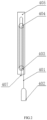
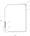
- FIG. 1 is a schematic drawing of a protective apparatus according to the first embodiment of the present application when it is in a closed state
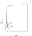
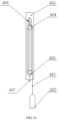
- FIG. 2 is a schematic diagram of the structure of the pull-down apparatus in Figure 1
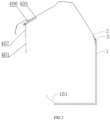
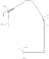
- FIG. 3 is a schematic diagram of the structure of the first embodiment of protective apparatus when it is in the open state
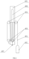
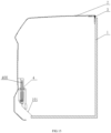
- FIG. 4 is a schematic diagram of the structure of the pull-down apparatus in Figure 3 .
- a specific implementation of the present application provides a protective apparatus, comprising a bracket 1 and a cover 2, the upper side of the cover 2 and the upper side of the bracket 1 can be hinged by rotating hinge 3, also comprises a pull-down apparatus 4, the pull-down apparatus 4 comprises fixed pulley 403, movable pulley 404, push rod 407 and pull rope 401, the fixed pulley 403 is fixed with the cover part 2, the movable pulley 404 is located above the fixed pulley 403, the movable pulley 404 and the covering piece 2 sliding connection, the fixed end of the pull rope 401 bypass the movable pulley 404 is connected to the fixed pulley 403, the upper end of the push rod 407 is connection with the movable pulley 404.
- the push rod 407 and the moving pulley 404 move down under the action of gravity to make the handle end 402 of the pull rope 401 hang down, so as to facilitate the operator to pull the handle end 402;
- the cover 2 needs to be closed, pull the handle end 402 downward, and the cover 2 moves down.
- the reverse push movable pulley 404 moves up.
- the handle end 402 of the pull rope 401 moves up, so as to store the pull rope 401.
- the pull-down apparatus 4 is a full mechanical structure, which does not require the use of a electric motor to pull the pull rope 401, so the structure is simple and easy to maintain.
- the pull-down apparatus 4 also comprises a supporting plate 405, wherein the supporting plate 405 is preferably located on the inner side of the cover 2. Therefore, after closing the cover 2, the pull-down apparatus 4 could be located inside the protective apparatus to protect the pull-down apparatus 4.
- the supporting plate 405 is fixed connected to the inner wall of the cover 2, for example, it could be connected by welding or fasteners, the supporting plate 405 is provided with a chute 406, the fixed pulley 403 is arranged at the bottom of the supporting plate 405, the movable pulley 404 and chute 406 sliding connection, wherein the supporting plate 405 is preferably arranged vertically in the inner side of the slat of the cover 2, the chute 406 extends along the length direction of the corresponding slat.
- the upper end of the push rod 407 is hinged with the movable pulley 404, that is, the push rod 407 could always be in the vertical state after the cover 2 is opened.
- a limiting part 101 is provided at the bottom of the bracket 1 to lean against the push rod 407.
- the upper part of the limiting part 101 and the lower end of the push rod 407 are respectively provided with a cushion block.
- FIG. 9 to FIG. 12 which also comprises the elastic part, wherein both ends of the elastic part are connected to the cover 2 and the movable pulley 404 respectively.
- the movable pulley 404 moves downward under the combined action of its gravity and the elastic force of the elastic part to ensure that the handle end 402 of the pull rope 401 hangs down;
- the elastic part compresses and deforms after pushing rod 407 press against bracket 1, so that when the cover 2 is opened again, the movable pulley 404 and pushing rod 407 are pushed down through the elastic action of the elastic part.
- the elastic part is preferred to spring 408, the upper end of the spring 408 is connected to the cover 2, and the lower end of the spring 408 is connected to the movable pulley 404.
- the pull-down apparatus 4 comprises multiple fixed pulleys 403 and multiple movable pulleys 404, and the pull rope 401 sequentially bypasses the movable pulleys 404 and 403.
- the ratio of the length of the pull rope 401 to the rising height of the push rod 407 would be increased.
- the ratio of the length of rope 401 to the rising height of the push rod 407 is 2:1.
- the ratio of the length of rope 401 to the rising height of the push rod 407 is 4:1.
- the present application embodiment also provides an aerial work device, comprising the protective apparatus provided in any of the above embodiments.
- bracket 1 could be a turntable side plate and a turntable tray.
- the beneficial effect of the aerial work device could be referred to the above protective apparatus, which would not be described here.
Landscapes
- Engineering & Computer Science (AREA)
- General Engineering & Computer Science (AREA)
- Structural Engineering (AREA)
- Life Sciences & Earth Sciences (AREA)
- Geology (AREA)
- Mechanical Engineering (AREA)
- Forklifts And Lifting Vehicles (AREA)
- Emergency Lowering Means (AREA)
- Electric Cable Installation (AREA)
Claims (10)
- Schutzvorrichtung, enthaltend eine Halterung (1) und eine Abdeckung (2), wobei die obere Seite der Abdeckung (2) gelenkig mit der oberen Seite der Halterung (1) verbunden ist,wobei die Schutzvorrichtung eine Abzugsvorrichtung (4) aufweist, wobei die Abzugsvorrichtung (4) eine feste Umlenkrolle (403), eine bewegliche Umlenkrolle (404), eine Schubstange (407) und ein Zugseil (401) enthält,wobei die feste Umlenkrolle (403) fest mit der Abdeckung (2) verbunden ist, die bewegliche Umlenkrolle (404) sich oberhalb der festen Umlenkrolle (403) befindet, die bewegliche Umlenkrolle (404) verschiebbar mit der Abdeckung (2) verbunden ist, das feste Ende des Zugseils (401), das an der beweglichen Umlenkrolle (404) vorbeiläuft, mit der festen Umlenkrolle (403) verbunden ist, das obere Ende der Schubstange (407) mit der beweglichen Umlenkrolle (404) verbunden ist, die Schubstange (407) und die bewegliche Umlenkrolle (404) bewirken, dass das Handgriff-Ende (402) des Zugseils (401) unter der Wirkung der Schwerkraft nach unten hängt, undwobei durch nach unten Ziehen des Handgriff-Endes (402) des Zugseils (401) zum Bewegen der Abdeckung (2) nach unten, nachdem das untere Ende der Schubstange (407) die Halterung (1) berührt, die Schubstange (407) die bewegliche Umlenkrolle (404) nach oben drückt, um das Handgriff-Ende (402) des Zugseils (401) nach oben zu drücken.
- Schutzvorrichtung nach Anspruch 1, wobei die Abzugsvorrichtung (4) ferner eine Stützplatte (405) enthält, die Stützplatte (405) fest mit der Abdeckung (2) verbunden ist, die Stützplatte (405) mit einer Rutsche (406) versehen ist, die feste Umlenkrolle (403) am Boden der Stützplatte (405) angeordnet ist, die bewegliche Umlenkrolle (404) verschiebbar mit der Rutsche (406) verbunden ist.
- Schutzvorrichtung nach Anspruch 2, wobei die Stützplatte (405) fest mit der Innenwand der Abdeckung (2) verbunden ist.
- Schutzvorrichtung nach Anspruch 1, wobei das obere Ende der Schubstange (407) gelenkig mit der beweglichen Umlenkrolle (404) verbunden ist.
- Schutzvorrichtung nach Anspruch 1, wobei der Boden der Halterung (1) mit einem Begrenzungsteil (101) zum Lehnen gegen die Schubstange (407) versehen ist.
- Schutzvorrichtung nach Anspruch 5, wobei der obere Teil des Begrenzungsteils (101) und das untere Ende der Schubstange (407) jeweils mit einem Dämpfungsblock versehen sind.
- Schutzvorrichtung nach Anspruch 1, wobei sie ein elastisches Teil enthält, wobei zwei Enden des elastischen Teils jeweils mit der Abdeckung bzw. der beweglichen Umlenkrolle verbunden sind und die bewegliche Umlenkrolle sich nach unten unter der Wirkung ihrer Schwerkraft und der elastischen Kraft des elastischen Teils bewegt, und wobei das elastische Teil einer Kompression und Deformation unterliegt, nachdem die Schubstange gegen die Halterung (1) gedrückt wird.
- Schutzvorrichtung nach Anspruch 7, wobei das elastische Teil eine Feder ist, der obere Teil der Feder mit der Abdeckung (2) verbunden ist und das untere Ende der Feder mit der beweglichen Umlenkrolle (404) verbunden ist.
- Schutzvorrichtung nach einem der Ansprüche 1 bis 8, wobei die Abzugsvorrichtung (4) mehrere feste Umlenkrollen (403) und mehrere bewegliche Umlenkrollen (404) enthält, und das Zugseil (401) nacheinander an den festen Umlenkrollen (404) und den beweglichen Umlenkrollen (403) vorbeiläuft.
- Luftarbeitsvorrichtung, wobei sie die Schutzvorrichtung nach einem der Ansprüche 1 bis 9 enthält.
Applications Claiming Priority (2)
| Application Number | Priority Date | Filing Date | Title |
|---|---|---|---|
| CN202011423985.0A CN112431501B (zh) | 2020-12-08 | 2020-12-08 | 一种防护装置及高空作业设备 |
| PCT/CN2021/135277 WO2022121791A1 (zh) | 2020-12-08 | 2021-12-03 | 一种防护装置及高空作业设备 |
Publications (4)
| Publication Number | Publication Date |
|---|---|
| EP4227482A1 EP4227482A1 (de) | 2023-08-16 |
| EP4227482A4 EP4227482A4 (de) | 2024-10-09 |
| EP4227482C0 EP4227482C0 (de) | 2025-05-07 |
| EP4227482B1 true EP4227482B1 (de) | 2025-05-07 |
Family
ID=74691732
Family Applications (1)
| Application Number | Title | Priority Date | Filing Date |
|---|---|---|---|
| EP21902498.1A Active EP4227482B1 (de) | 2020-12-08 | 2021-12-03 | Schutzvorrichtung und luftarbeitsvorrichtung |
Country Status (5)
| Country | Link |
|---|---|
| US (1) | US12497813B2 (de) |
| EP (1) | EP4227482B1 (de) |
| CN (1) | CN112431501B (de) |
| PL (1) | PL4227482T3 (de) |
| WO (1) | WO2022121791A1 (de) |
Families Citing this family (1)
| Publication number | Priority date | Publication date | Assignee | Title |
|---|---|---|---|---|
| CN112431501B (zh) * | 2020-12-08 | 2025-01-10 | 湖南星邦智能装备股份有限公司 | 一种防护装置及高空作业设备 |
Family Cites Families (21)
| Publication number | Priority date | Publication date | Assignee | Title |
|---|---|---|---|---|
| GB124134A (en) * | 1918-07-09 | 1919-03-20 | Simon Moyse | Window Opening, Closing and Locking Apparatus. |
| GB579348A (en) * | 1944-03-09 | 1946-07-31 | John Irwin Adams | Operating gear for pivoted sky-lights and fan-lights |
| DE29920826U1 (de) * | 1999-11-26 | 2000-02-03 | Adam Opel AG, 65428 Rüsselsheim | Klappe zum Verschließen einer Karosserieöffnung |
| JP2001220946A (ja) * | 1999-12-03 | 2001-08-17 | Nippon Cable Syst Inc | プルケーブル式のサンルーフなどの開閉装置 |
| TW443419U (en) * | 2000-08-29 | 2001-06-23 | Yan Wen Shiung | Ventilation window |
| CN2516684Y (zh) * | 2001-11-28 | 2002-10-16 | 翁景天 | 内置开启式防盗窗 |
| US20030183633A1 (en) * | 2002-04-02 | 2003-10-02 | Arnold Pope | Container lid lifting device |
| US7533600B2 (en) * | 2006-06-30 | 2009-05-19 | International Truck Intellectual Property Company, Llc | Armor assembly for a truck |
| FR2904645A1 (fr) * | 2006-08-04 | 2008-02-08 | Elisabeth Ruat | Dispositif d'aide au relevage d'un panneau |
| JP4873354B2 (ja) * | 2009-11-09 | 2012-02-08 | 関東自動車工業株式会社 | ハンドル装置及びそれを備えた車両 |
| CN202831968U (zh) | 2012-08-17 | 2013-03-27 | 湖北合加环境设备有限公司 | 安全检修门 |
| CN203742648U (zh) * | 2013-09-30 | 2014-07-30 | 新汶矿业集团有限责任公司鄂庄煤矿 | 巷道风门开启泄压联动装置 |
| CN203976288U (zh) * | 2014-07-08 | 2014-12-03 | 国家电网公司 | 一种翻板式滑轮悬挂装置 |
| US9702665B1 (en) * | 2016-08-01 | 2017-07-11 | Burose, LLC | Ballistic shade system |
| CN206035198U (zh) * | 2016-08-31 | 2017-03-22 | 酒泉奥凯种子机械股份有限公司 | 料仓进料门板启闭装置 |
| CN208087119U (zh) * | 2018-01-05 | 2018-11-13 | 青岛诺诚化学品安全科技有限公司 | 一种气缸滑轮组提升装置 |
| KR102241812B1 (ko) * | 2019-02-27 | 2021-04-16 | 안희문 | 전동식으로 높이조절이 가능한 특장차용 조종석 캐빈 |
| CN210195797U (zh) | 2019-08-02 | 2020-03-27 | 郑州鑫安矿山机械配件有限公司 | 一种便于开启的单扇风门 |
| CN211500452U (zh) | 2019-10-23 | 2020-09-15 | 王征跃 | 一种可移动式猫眼 |
| CN112431501B (zh) | 2020-12-08 | 2025-01-10 | 湖南星邦智能装备股份有限公司 | 一种防护装置及高空作业设备 |
| CN214145149U (zh) * | 2020-12-08 | 2021-09-07 | 湖南星邦智能装备股份有限公司 | 一种防护装置及高空作业设备 |
-
2020
- 2020-12-08 CN CN202011423985.0A patent/CN112431501B/zh active Active
-
2021
- 2021-12-03 WO PCT/CN2021/135277 patent/WO2022121791A1/zh not_active Ceased
- 2021-12-03 US US18/265,243 patent/US12497813B2/en active Active
- 2021-12-03 EP EP21902498.1A patent/EP4227482B1/de active Active
- 2021-12-03 PL PL21902498.1T patent/PL4227482T3/pl unknown
Also Published As
| Publication number | Publication date |
|---|---|
| CN112431501B (zh) | 2025-01-10 |
| EP4227482A1 (de) | 2023-08-16 |
| US12497813B2 (en) | 2025-12-16 |
| PL4227482T3 (pl) | 2025-07-07 |
| WO2022121791A1 (zh) | 2022-06-16 |
| CN112431501A (zh) | 2021-03-02 |
| EP4227482A4 (de) | 2024-10-09 |
| EP4227482C0 (de) | 2025-05-07 |
| US20240003177A1 (en) | 2024-01-04 |
Similar Documents
| Publication | Publication Date | Title |
|---|---|---|
| EP4227482B1 (de) | Schutzvorrichtung und luftarbeitsvorrichtung | |
| CN110280680A (zh) | 一种具有保护功能的汽车整车制造用冲压装置和工作方法 | |
| CN219320859U (zh) | 森林自然火灾监测保护装置 | |
| CN105305255A (zh) | 一种具有自动防护功能的电气柜装置 | |
| CN117184199A (zh) | 一种电缆转运装置 | |
| CN205240415U (zh) | 一种自动掀盖的防护装置 | |
| CN214145149U (zh) | 一种防护装置及高空作业设备 | |
| CN207329764U (zh) | 一种光伏玻璃板自动上料机用的直线移送平台 | |
| CN118676759B (zh) | 一种具有防护功能的配电箱 | |
| CN202957503U (zh) | 一种关门联锁的底盘车 | |
| CN210156901U (zh) | 一种地埋式分接箱 | |
| CN213878932U (zh) | 带伸缩式天线结构的无线电力控制设备 | |
| CN220671500U (zh) | 便携式过电压保护试验装置 | |
| CN211594658U (zh) | 一种桥梁施工的液压起重机构 | |
| CN114336375A (zh) | 一种基于电气自动化控制柜远程锁定装置 | |
| CN223620013U (zh) | 一种电气施工吊装架 | |
| CN221971179U (zh) | 一种输变电设备安装施工装置 | |
| CN112054472A (zh) | 一种雨天自动升降式避雷器 | |
| CN115567150B (zh) | 一种数字信号屏蔽管控装置 | |
| CN218061757U (zh) | 一种新型便携式安全围栏 | |
| CN220401180U (zh) | 一种低压固定式开关柜 | |
| CN206585258U (zh) | 一种活门结构 | |
| CN223244713U (zh) | 一种轻型化主缆检测维修装置 | |
| CN221568220U (zh) | 一种具有防夹功能的智能开窗器 | |
| CN219107575U (zh) | 一种便于移动的通讯基站 |
Legal Events
| Date | Code | Title | Description |
|---|---|---|---|
| STAA | Information on the status of an ep patent application or granted ep patent |
Free format text: STATUS: THE INTERNATIONAL PUBLICATION HAS BEEN MADE |
|
| PUAI | Public reference made under article 153(3) epc to a published international application that has entered the european phase |
Free format text: ORIGINAL CODE: 0009012 |
|
| STAA | Information on the status of an ep patent application or granted ep patent |
Free format text: STATUS: REQUEST FOR EXAMINATION WAS MADE |
|
| 17P | Request for examination filed |
Effective date: 20230510 |
|
| AK | Designated contracting states |
Kind code of ref document: A1 Designated state(s): AL AT BE BG CH CY CZ DE DK EE ES FI FR GB GR HR HU IE IS IT LI LT LU LV MC MK MT NL NO PL PT RO RS SE SI SK SM TR |
|
| DAV | Request for validation of the european patent (deleted) | ||
| DAX | Request for extension of the european patent (deleted) | ||
| A4 | Supplementary search report drawn up and despatched |
Effective date: 20240910 |
|
| RIC1 | Information provided on ipc code assigned before grant |
Ipc: B66F 11/04 20060101ALI20240904BHEP Ipc: E05F 11/04 20060101AFI20240904BHEP |
|
| GRAP | Despatch of communication of intention to grant a patent |
Free format text: ORIGINAL CODE: EPIDOSNIGR1 |
|
| STAA | Information on the status of an ep patent application or granted ep patent |
Free format text: STATUS: GRANT OF PATENT IS INTENDED |
|
| RIC1 | Information provided on ipc code assigned before grant |
Ipc: B66F 11/04 20060101ALI20250123BHEP Ipc: E05F 11/04 20060101AFI20250123BHEP |
|
| INTG | Intention to grant announced |
Effective date: 20250131 |
|
| GRAS | Grant fee paid |
Free format text: ORIGINAL CODE: EPIDOSNIGR3 |
|
| GRAA | (expected) grant |
Free format text: ORIGINAL CODE: 0009210 |
|
| STAA | Information on the status of an ep patent application or granted ep patent |
Free format text: STATUS: THE PATENT HAS BEEN GRANTED |
|
| RAP3 | Party data changed (applicant data changed or rights of an application transferred) |
Owner name: HUNAN SINOBOOM INTELLIGENT EQUIPMENT CO., LTD. |
|
| AK | Designated contracting states |
Kind code of ref document: B1 Designated state(s): AL AT BE BG CH CY CZ DE DK EE ES FI FR GB GR HR HU IE IS IT LI LT LU LV MC MK MT NL NO PL PT RO RS SE SI SK SM TR |
|
| REG | Reference to a national code |
Ref country code: GB Ref legal event code: FG4D |
|
| REG | Reference to a national code |
Ref country code: CH Ref legal event code: EP |
|
| REG | Reference to a national code |
Ref country code: DE Ref legal event code: R096 Ref document number: 602021030612 Country of ref document: DE |
|
| REG | Reference to a national code |
Ref country code: IE Ref legal event code: FG4D |
|
| U01 | Request for unitary effect filed |
Effective date: 20250508 |
|
| U07 | Unitary effect registered |
Designated state(s): AT BE BG DE DK EE FI FR IT LT LU LV MT NL PT RO SE SI Effective date: 20250515 |
|
| PG25 | Lapsed in a contracting state [announced via postgrant information from national office to epo] |
Ref country code: ES Free format text: LAPSE BECAUSE OF FAILURE TO SUBMIT A TRANSLATION OF THE DESCRIPTION OR TO PAY THE FEE WITHIN THE PRESCRIBED TIME-LIMIT Effective date: 20250507 |
|
| PG25 | Lapsed in a contracting state [announced via postgrant information from national office to epo] |
Ref country code: GR Free format text: LAPSE BECAUSE OF FAILURE TO SUBMIT A TRANSLATION OF THE DESCRIPTION OR TO PAY THE FEE WITHIN THE PRESCRIBED TIME-LIMIT Effective date: 20250808 Ref country code: NO Free format text: LAPSE BECAUSE OF FAILURE TO SUBMIT A TRANSLATION OF THE DESCRIPTION OR TO PAY THE FEE WITHIN THE PRESCRIBED TIME-LIMIT Effective date: 20250807 |
|
| PG25 | Lapsed in a contracting state [announced via postgrant information from national office to epo] |
Ref country code: HR Free format text: LAPSE BECAUSE OF FAILURE TO SUBMIT A TRANSLATION OF THE DESCRIPTION OR TO PAY THE FEE WITHIN THE PRESCRIBED TIME-LIMIT Effective date: 20250507 |
|
| PG25 | Lapsed in a contracting state [announced via postgrant information from national office to epo] |
Ref country code: RS Free format text: LAPSE BECAUSE OF FAILURE TO SUBMIT A TRANSLATION OF THE DESCRIPTION OR TO PAY THE FEE WITHIN THE PRESCRIBED TIME-LIMIT Effective date: 20250807 |
|
| PG25 | Lapsed in a contracting state [announced via postgrant information from national office to epo] |
Ref country code: IS Free format text: LAPSE BECAUSE OF FAILURE TO SUBMIT A TRANSLATION OF THE DESCRIPTION OR TO PAY THE FEE WITHIN THE PRESCRIBED TIME-LIMIT Effective date: 20250907 |
|
| U20 | Renewal fee for the european patent with unitary effect paid |
Year of fee payment: 5 Effective date: 20251110 |
|
| PGFP | Annual fee paid to national office [announced via postgrant information from national office to epo] |
Ref country code: GB Payment date: 20251030 Year of fee payment: 5 |
|
| PG25 | Lapsed in a contracting state [announced via postgrant information from national office to epo] |
Ref country code: SM Free format text: LAPSE BECAUSE OF FAILURE TO SUBMIT A TRANSLATION OF THE DESCRIPTION OR TO PAY THE FEE WITHIN THE PRESCRIBED TIME-LIMIT Effective date: 20250507 |
|
| PG25 | Lapsed in a contracting state [announced via postgrant information from national office to epo] |
Ref country code: CZ Free format text: LAPSE BECAUSE OF FAILURE TO SUBMIT A TRANSLATION OF THE DESCRIPTION OR TO PAY THE FEE WITHIN THE PRESCRIBED TIME-LIMIT Effective date: 20250507 |
|
| PGFP | Annual fee paid to national office [announced via postgrant information from national office to epo] |
Ref country code: PL Payment date: 20251103 Year of fee payment: 5 |
|
| PG25 | Lapsed in a contracting state [announced via postgrant information from national office to epo] |
Ref country code: SK Free format text: LAPSE BECAUSE OF FAILURE TO SUBMIT A TRANSLATION OF THE DESCRIPTION OR TO PAY THE FEE WITHIN THE PRESCRIBED TIME-LIMIT Effective date: 20250507 |