EP4222003B1 - Reifen mit einer optimierten schicht aus selbstdichtendem produkt - Google Patents
Reifen mit einer optimierten schicht aus selbstdichtendem produkt Download PDFInfo
- Publication number
- EP4222003B1 EP4222003B1 EP21798067.1A EP21798067A EP4222003B1 EP 4222003 B1 EP4222003 B1 EP 4222003B1 EP 21798067 A EP21798067 A EP 21798067A EP 4222003 B1 EP4222003 B1 EP 4222003B1
- Authority
- EP
- European Patent Office
- Prior art keywords
- cut
- axially
- axial
- rib
- self
- Prior art date
- Legal status (The legal status is an assumption and is not a legal conclusion. Google has not performed a legal analysis and makes no representation as to the accuracy of the status listed.)
- Active
Links
Images

Classifications
-
- B—PERFORMING OPERATIONS; TRANSPORTING
- B60—VEHICLES IN GENERAL
- B60C—VEHICLE TYRES; TYRE INFLATION; TYRE CHANGING; CONNECTING VALVES TO INFLATABLE ELASTIC BODIES IN GENERAL; DEVICES OR ARRANGEMENTS RELATED TO TYRES
- B60C19/00—Tyre parts or constructions not otherwise provided for
- B60C19/12—Puncture preventing arrangements
- B60C19/122—Puncture preventing arrangements disposed inside of the inner liner
-
- B—PERFORMING OPERATIONS; TRANSPORTING
- B29—WORKING OF PLASTICS; WORKING OF SUBSTANCES IN A PLASTIC STATE IN GENERAL
- B29C—SHAPING OR JOINING OF PLASTICS; SHAPING OF MATERIAL IN A PLASTIC STATE, NOT OTHERWISE PROVIDED FOR; AFTER-TREATMENT OF THE SHAPED PRODUCTS, e.g. REPAIRING
- B29C73/00—Repairing of articles made from plastics or substances in a plastic state, e.g. of articles shaped or produced by using techniques covered by this subclass or subclass B29D
- B29C73/16—Auto-repairing or self-sealing arrangements or agents
- B29C73/18—Auto-repairing or self-sealing arrangements or agents the article material itself being self-sealing, e.g. by compression
-
- B—PERFORMING OPERATIONS; TRANSPORTING
- B60—VEHICLES IN GENERAL
- B60C—VEHICLE TYRES; TYRE INFLATION; TYRE CHANGING; CONNECTING VALVES TO INFLATABLE ELASTIC BODIES IN GENERAL; DEVICES OR ARRANGEMENTS RELATED TO TYRES
- B60C11/00—Tyre tread bands; Tread patterns; Anti-skid inserts
- B60C11/03—Tread patterns
- B60C11/04—Tread patterns in which the raised area of the pattern consists only of continuous circumferential ribs, e.g. zig-zag
- B60C11/042—Tread patterns in which the raised area of the pattern consists only of continuous circumferential ribs, e.g. zig-zag further characterised by the groove cross-section
-
- B—PERFORMING OPERATIONS; TRANSPORTING
- B60—VEHICLES IN GENERAL
- B60C—VEHICLE TYRES; TYRE INFLATION; TYRE CHANGING; CONNECTING VALVES TO INFLATABLE ELASTIC BODIES IN GENERAL; DEVICES OR ARRANGEMENTS RELATED TO TYRES
- B60C19/00—Tyre parts or constructions not otherwise provided for
- B60C19/12—Puncture preventing arrangements
-
- B—PERFORMING OPERATIONS; TRANSPORTING
- B60—VEHICLES IN GENERAL
- B60C—VEHICLE TYRES; TYRE INFLATION; TYRE CHANGING; CONNECTING VALVES TO INFLATABLE ELASTIC BODIES IN GENERAL; DEVICES OR ARRANGEMENTS RELATED TO TYRES
- B60C11/00—Tyre tread bands; Tread patterns; Anti-skid inserts
- B60C11/03—Tread patterns
- B60C2011/0337—Tread patterns characterised by particular design features of the pattern
- B60C2011/0339—Grooves
Definitions
- the present invention relates to a pneumatic tire.
- pneumatic tire is meant a bandage intended to form a cavity by cooperating with a support element, for example a rim, this cavity being capable of being pressurized to a pressure higher than atmospheric pressure.
- a pneumatic tire according to the invention has a structure of substantially toroidal shape of revolution around a main axis of the pneumatic tire.
- EP2629964 a tire comprising a tread intended to come into contact with the ground during rolling of the tire via a rolling surface.
- the tread comprises main circumferential cutouts as well as central ribs arranged axially respectively between two adjacent main circumferential cutouts and delimited axially by said two adjacent main circumferential cutouts.
- the tire of EP2629964 comprises an inner sealing layer for forming a cavity sealed against inflation gas when the tire is mounted on a mounting support, for example a rim, and a layer of a self-sealing product extending circumferentially radially inside a portion of the inner sealing layer.
- the layer of self-sealing product allows, in the event of a puncture of the tyre due to a piercing object, to seal the orifice created by the piercing object under the effect of the internal pressure of the tyre. Indeed, under the effect of the internal pressure of the tyre, the self-sealing product is caused to flow into the orifice for the air to flow outwards, in order to seal it and restore the seal to the inflation gas.
- the aim of the invention is to provide a tire provided with a layer of sealing product that is as light as possible and whose layer of self-sealing product is substantially as effective against perforations as the layers of self-sealing product of tires of the prior art.
- the inventors behind the invention determined that the axial portions of the tread most likely to be punctured were the ribs in which the deepest transverse cuts were made. According to the invention, these axial portions include transverse cuts having a depth at least equal to half the tread height. Thus, the invention provides a relatively high average thickness Ec of self-sealing product at the level of these deeply cut ribs, which makes it possible to guarantee a high efficiency of the layer of self-sealing product against perforations occurring in these deeply cut ribs.
- ribs that are little or slightly cut are statistically less likely to suffer perforations. Indeed, in the case of an uncut rib, a relatively large thickness of the tread provides greater resistance to perforation compared to a relatively small thickness. In the case of a weakly cut rib comprising shallow transverse cuts, on the one hand, the thickness of the tread protects the tire from perforation in the case where the perforating object is relatively short and, on the other hand, a relatively large thickness of the tread provides greater resistance to perforation compared to a relatively small thickness. Furthermore, in the case of a weakly cut rib comprising narrow transverse cuts, the probability of a perforating object becoming lodged therein is relatively low. Thus, the invention provides a relatively small, or even zero, average thickness Eb of self-sealing product at the level of the non-cut or weakly cut ribs, which makes it possible to significantly lighten the tire.
- the self-sealing product layer allows, in the event of a puncture of the tyre due to a piercing object, to seal the orifice created by the piercing object under the effect of the internal pressure of the tyre. Indeed, under the effect of the internal pressure of the tyre, the self-sealing product is caused to flow into the air flow orifice towards the outside, in order to seal it and restore the seal to the inflation gas.
- the self-sealing product layer consists of a single self-sealing product.
- the self-sealing product is arranged in contact with the inflation gas present in the cavity delimited at least in part by the self-sealing product and a tire mounting support, for example a rim, when the tire is mounted on the mounting support.
- the axial portion of the layer of self-sealing product arranged at a deeply cut rib or an uncut or slightly cut rib of the tread is the axial portion of self-sealing product delimited by axial ends defined by two circumferential planes perpendicular to the axis of rotation of the tire and passing respectively through the axial ends of the corresponding rib.
- a so-called thick axial portion of the layer of self-sealing product has an axial width greater than the axial width of the deeply cut rib, only a portion of the thick axial portion of the layer of self-sealing product is located at the deeply cut rib.
- the entire thick axial portion of the layer of self-sealing product is located at the level of the deeply cut rib.
- a so-called thin axial portion of the layer of self-sealing product has an axial width greater than the axial width of the non- or weakly cut rib, only a portion of the thin axial portion of the layer of self-sealing product is located at the level of the non- or weakly cut rib.
- the entire thin axial portion of the layer of self-sealing product is located at the level of the non- or weakly cut rib.
- the invention is advantageous, without this constituting an essential characteristic, in the embodiments in which the or each transverse cut of the or each deeply cut rib is particularly deep, that is to say for which Ht/Hs ⁇ 75% and more preferably Ht/Hs ⁇ 90%.
- the invention is advantageous, without this constituting an essential characteristic, in the embodiments in which the or each transverse cutout of the or each weakly cut rib is particularly narrow, that is to say for which its width is strictly less than 1.6 mm and more preferably strictly less than 1.0 mm.
- the invention is also advantageous without this constituting a essential characteristic, in the embodiments in which the or each transverse cut of the or each weakly cut rib is particularly shallow, that is to say for which H/Hs ⁇ 30%.
- transverse cutouts described above concerning the transverse cutouts of the or each weakly cut rib are satisfied for at least 50%, preferably for at least 75% and more preferably for 100% of the number of transverse cutouts of the or each weakly cut rib.
- the layer of self-sealing product has the essential characteristics of the invention over at least 50% of the circumferential length of the layer of self-sealing product makes it possible to envisage embodiments in which the tire is devoid of a layer of self-sealing product over at most 50% of the circumferential length of the layer of self-sealing product or else embodiments in which the layer of self-sealing product extends over 100% of the circumferential length of the layer of self-sealing product without having the essential characteristics over 100% of the circumferential length.
- the layer of self-sealing product has the essential characteristics of the invention over at least 75%, more preferably over at least 95% and ideally over 100% of the circumferential length of the layer of self-sealing product.
- each axial portion of the layer of self-sealing product extending in line with the or each deeply cut and non-cut or slightly cut rib extends circumferentially continuously over at least 50%, preferably over at least 75%, more preferably over at least 95% and ideally over 100% of the circumferential length of the layer of self-sealing product.
- the invention also makes it possible to envisage axial portions of the self-sealing product layer which have variable thicknesses in the circumferential direction.
- the average thickness of each axial portion of the self-sealing product layer extending at the or each deeply cut and non- or weakly cut rib is circumferentially substantially constant over at least 50%, preferably over at least 75% and more preferably over at least 95% and ideally over 100% of the circumferential length of the layer of self-sealing product.
- Each average thickness Eb, Ec of the axial portion of the layer of self-sealing product extending axially in line with each deeply cut and uncut or slightly cut rib is measured by taking, in several meridian cutting planes, an average of the thicknesses of the layer of self-sealing product between the axial ends of said axial portion of the layer of self-sealing product, the thicknesses being measured for example every millimeter.
- the average thickness is substantially constant circumferentially, a reduced number of meridian cutting planes will be taken.
- the average thickness is not constant circumferentially, a significant number of meridian cutting planes will be taken, for example sixteen, and the average of the thicknesses measured in all the meridian cutting planes will be taken.
- the thickness measured at a point is obviously the shortest straight distance separating the radially outer surface and the radially inner surface of the layer of self-sealing product passing through this point. It should be noted that the cuts in the meridian cutting planes are made without damaging the layer of self-sealing product in order to accurately measure the various geometric quantities, in particular the thicknesses. In particular, very high pressure water jet cutting processes will be used.
- the depth of a cut is, on a new tire, the maximum radial distance between the bottom of the cut and its projection on the ground when the tire is rolling.
- the maximum value of the depths of the cuts is called the tread height.
- a cutout is either a groove or an incision and forms a space opening onto the running surface.
- An incision or groove has, on the rolling surface, two main characteristic dimensions: a width and a curvilinear length such that the curvilinear length is at least twice the width.
- An incision or groove is therefore delimited by at least two main lateral faces determining its curvilinear length and connected by a bottom face, the two main lateral faces being distant from each other by a non-zero distance, called the width of the cutout.
- the width of a cut is, on a new tyre, the maximum distance between the two main lateral faces measured, in the case where the cut does not include a chamfer, at a radial dimension coincident with the rolling surface, and in the case where the cut includes a chamfer, at the widest radial dimension radially outside the cutout and radially inside the chamfer.
- the width is measured substantially perpendicular to the main side faces.
- the axial width of a cutout is measured along the axial direction of the tire, for example in a meridian cutting plane of the tire.
- An incision is such that the distance between the main lateral faces is suitable to allow at least partial contact of the main lateral faces delimiting said incision when passing through the contact area, in particular when the tire is new and under normal driving conditions, including in particular the fact that the tire is at nominal load and nominal pressure.
- a groove is such that the distance between the main lateral faces is such that these main lateral faces cannot come into contact with each other under normal driving conditions, including in particular the fact that the tire is at nominal load and nominal pressure.
- a cutout can be transverse or circumferential.
- a transverse cut is such that the cut extends in a mean direction forming an angle strictly greater than 30°, preferably greater than or equal to 45° with the circumferential direction of the tire.
- the mean direction is the shortest curve joining the two ends of the cut and parallel to the rolling surface.
- a transverse cut may be continuous, i.e. not interrupted by a tread block or another cut such that the two main lateral faces determining its length are uninterrupted over the length of the transverse cut.
- a transverse cut may also be discontinuous, i.e. interrupted by one or more tread blocks and/or one or more cuts such that the two main lateral faces determining its length are interrupted by one or more tread blocks and/or one or more cuts.
- a circumferential cutout is such that the cutout extends in a mean direction forming an angle of less than or equal to 30°, preferably less than or equal to 10°, with the circumferential direction of the tire.
- the mean direction is the shortest curve joining the two ends of the cutout and parallel to the running surface. In the case of a continuous circumferential cutout, the two ends coincide with each other and are joined by a curve making a complete turn of the tire.
- a circumferential cutout may be continuous, i.e. not interrupted by a tread block or another cutout so that the two main lateral faces determining its length are uninterrupted on the entire turn of the tire.
- a circumferential cut may also be discontinuous, i.e. interrupted by one or more tread blocks and/or one or more cuts such that the two main lateral faces determining its length are interrupted by one or more tread blocks and/or one or more cuts over the entire turn of the tire.
- the lateral faces are called axially inner faces and axially outer face, the axially inner face being arranged, at a given azimuth, axially inside the axially outer face relative to the median plane.
- Each circumferential cutout comprises axially inner and outer axial ends. Whether in the case of a circumferential cutout without a chamfer or provided with a chamfer, each axially inner and outer axial end coincides with each axial edge of the circumferential cutout located on the rolling surface and therefore in contact with a rolling ground.
- the side faces are called the leading face and the trailing face, the leading face being the one whose edge, for a given circumferential line, enters the contact area before the edge of the trailing face.
- the or each circumferential cutout is provided with chamfers.
- a chamfer of a circumferential cutout may be a straight chamfer or a rounded chamfer.
- a straight chamfer is formed by a flat face inclined relative to the axially inner and outer face that it extends to the axially inner or outer edge axially delimiting the circumferential cutout.
- a rounded chamfer is formed by a curved face tangentially connecting to the axially inner or outer face that it extends.
- a chamfer of a circumferential cutout is characterized by a height and a width equal respectively to the radial distance and the axial distance between the common point between the axially inner or outer face extended by the chamfer and the axially inner or outer edge axially delimiting the circumferential cutout.
- each transverse cutout is provided with chamfers.
- each transverse cutout being delimited radially by leading and trailing faces circumferentially delimiting said transverse cutout and connected together by a bottom face delimiting radially inwardly said transverse cutout.
- a chamfer of a transverse cutout may be a straight chamfer or a rounded chamfer.
- a straight chamfer is formed by a flat face inclined relative to the leading or trailing face which it extends to the leading or trailing edge circumferentially delimiting the transverse cutout.
- a rounded chamfer is formed by a curved face connecting tangentially to the leading or trailing face that it extends.
- a chamfer of a transverse cutout is characterized by a height and a width equal respectively to the radial distance and to the distance in a direction perpendicular to the leading or trailing faces between the common point between the leading or trailing face extended by the chamfer and the leading or trailing edge circumferentially delimiting the transverse cutout.
- the axial ends of the tread are determined as the axial ends of the tire of the rolling surface in contact with a rolling ground on an unloaded tire mounted on a nominal rim and inflated to the nominal pressure within the meaning of the European Tyre and Rim Technical Organization or "ETRTO" standard, 2019.
- ERRTO European Tyre and Rim Technical Organization
- the axial ends of the tread are simply determined.
- each axial end of the tread passes through the point for which the angle between the tangent to the rolling surface and a straight line parallel to the axial direction passing through this point is equal to 30°.
- the radially outermost point is retained.
- the tire according to the invention has a substantially toric shape around an axis of revolution substantially coincident with the axis of rotation of the tire.
- This axis of revolution defines three directions conventionally used by those skilled in the art: an axial direction, a circumferential direction and a radial direction.
- axial direction is meant the direction substantially parallel to the axis of revolution of the tire, i.e. the axis of rotation of the tire.
- circumferential direction is meant the direction which is substantially perpendicular to both the axial direction and a radius of the tire (in other words, tangent to a circle whose center is on the axis of rotation of the tire).
- radial direction is meant the direction along a radius of the tire, that is to say any direction intersecting the axis of rotation of the tire and substantially perpendicular to this axis.
- median plane of the tire we mean the plane perpendicular to the axis of rotation of the tire which is located at mid-axial distance of the two beads and passes through the axial center of the crown reinforcement.
- equatorial circumferential plane of the tire we mean, in a meridian section plane, the plane passing through the equator of the tire, perpendicular to the median plane and to the radial direction.
- the equator of the tyre is, in a meridian section plane (plane perpendicular to the circumferential direction and parallel to the radial and axial directions) the axis parallel to the axis of rotation of the tyre and located equidistant between the radially outermost point of the tread intended to be in contact with the ground and the radially innermost point of the tyre intended to be in contact with a support, for example a rim, the distance between these two points being equal to H.
- meridian plane is meant a plane parallel to and containing the axis of rotation of the tire and perpendicular to the circumferential direction.
- radially inner, respectively radially outer is meant closer to the axis of rotation of the tire, respectively further from the axis of rotation of the tire.
- axially inner, respectively axially outer is meant closer to the median plane of the tire, respectively further from the median plane of the tire.
- each bead is meant the portion of the tire intended to allow the tire to be attached to a mounting support, for example a wheel comprising a rim.
- a mounting support for example a wheel comprising a rim.
- each bead is in particular intended to be in contact with a hook on the rim allowing it to be attached.
- any interval of values denoted by the expression "between a and b" represents the domain of values from greater than a to less than b (i.e., excluding the limits a and b), while any interval of values denoted by the expression “from a to b” signifies the domain of values from a to b (i.e., including the strict limits a and b).
- the tires are, in preferred embodiments of the invention, intended for passenger vehicles as defined within the meaning of the standard of the European Tyre and Rim Technical Organisation or "ETRTO", 2019.
- Such a tire has a section in a meridian section plane characterized by a section height H and a nominal section width or bead thickness S within the meaning of the standard of the European Tyre and Rim Technical Organisation or "ETRTO", 2019 such that the ratio H/S, expressed as a percentage, is at most equal to 90, preferably at most equal to 80 and more preferably at most equal to 70 and is at least equal to 30, preferably at least equal to 40, and the nominal section width S is at least equal to 115 mm, preferably at least equal to 155 mm and more preferably at least equal to 175 mm and at most equal to 385 mm, preferably at most equal to 315 mm, more preferably at most equal to 285 mm and even more preferably at most equal to 255 mm.
- the diameter at the hook D defining the diameter of the
- a rib delimited axially by an axial end of the tread and an axially inner or outer end of a main circumferential cutout it will generally be referred to as a lateral rib because it is located in a lateral portion of the tread.
- a rib delimited axially by an axially inner (or outer) end of a main circumferential cutout and by an adjacent axially outer (or inner) end of another main circumferential cutout it will generally be referred to as a central rib because it is located in a central portion of the tread.
- each circumferential cut is said to be principal because of its relatively large depth Ha compared to other complementary circumferential cuts which could optionally be present on the tread of the tire.
- Ec ⁇ 1.10 x Eb preferably Ec ⁇ 1.30 x Eb and more preferably Ec ⁇ 1.50 x Eb.
- Ec the higher the ratio Ec/Eb, the smaller the average thickness Eb of the axial portion extending axially in line with the uncut or slightly cut rib and the greater the weight saving.
- Ec the higher the ratio Ec/Eb, the greater the average thickness Ec of the axial portion extending axially in line with the deeply cut rib, which promotes the effectiveness of the sealing of a possible orifice in the deeply cut rib.
- Ec ⁇ 5.00 x Eb preferably Ec ⁇ 4.00 x Eb and more preferably Ec ⁇ 2.50 x Eb.
- Ec the higher the ratio
- Ec/Eb ratio the greater the average thickness Eb of the axial portion extending axially in line with the uncut or weakly cut rib and the greater the efficiency of sealing a possible hole in the uncut or weakly cut rib which, even if relatively small, still exists.
- Eb the smaller the Ec/Eb ratio, the smaller the average thickness Ec of the axial portion extending axially in line with the deeply cut rib, which makes it possible to reduce the mass of self-sealing product.
- Ec-Eb ⁇ 0.5 mm In embodiments allowing, as previously described, to maximize the compromise between the mass gain and the efficiency of the sealing of a possible orifice in the deeply cut rib, Ec-Eb ⁇ 0.5 mm, preferably Ec-Eb ⁇ 1.0 mm.
- each average thickness Ec advantageously ranges from 2.0 mm to 5.0 mm, preferably from 2.5 mm to 4.5 mm
- the average thickness Eb advantageously ranges from 0.5 mm to 4.0 mm, preferably from 1.0 mm to 3.0 mm.
- the layer of self-sealing product has, near the deeply cut rib, a significant axial width compared to the axial width of each deeply cut rib in order to be able to effectively seal any orifice.
- the self-sealing product layer comprises at least one axial portion, called thick, the or each thick axial portion being at least partly merged with all or part of the or each axial portion extending axially in line with the or each deeply cut rib, the or each thick axial portion being axially delimited by two adjacent inflection points of the radially inner surface curve of the self-sealing product layer, the thickness of said thick axial portion increasing by moving axially inward of said thick axial portion from each of said inflection points, the axial width Wy of the thick axial portion being such that Wy/Lcy ⁇ 0.50, preferably Wy/Lcy > 1.00 with Lcy being the axial width of said deeply cut rib.
- the thick axial portion may have an axial width less than the axial width of the deeply cut rib, but nevertheless sufficient to allow any orifice to be effectively sealed.
- the thick axial portion coincides with a portion of the axial portion of the layer of self-sealing product extending in line with the deeply cut rib.
- the thick axial portion may also preferably have an axial width greater than or equal to the axial width of the deeply cut rib. In this case, a portion of the thick axial portion coincides with the axial portion of the self-sealing product layer extending in line with the deeply cut rib.
- An inflection point is a point where, in a meridian section plane, the direction of curvature of the radially inner surface curve of the self-sealing product layer changes.
- An equal point is a stopping point of the radially inner surface curve of the self-sealing product layer in contact with the sealing layer.
- the axial width of the or each thick axial portion is the distance in the axial direction, for example measured in a meridian section plane, between the two inflection points.
- the or each transverse cutout of the or each deeply cut rib has a width greater than or equal to 0.7 mm, preferably greater than or equal to 1.0 mm and more preferably greater than or equal to 1.6 mm.
- the or each transverse cut of the or each deeply cut rib has a depth ranging from 2.0 mm to the tread height, preferably ranging from 4.0 mm to the tread height and more preferably ranging from 5.0 mm to the tread height.
- each axial end of the self-sealing product layer is arranged at an axial distance less than or equal to 20%, preferably less than or equal to 10% of the axial width of the tread relative to each axial end of the tread, preferably axially inside each axial end of the tread.
- each first and second axially lateral portion respectively comprises a first and a second deeply cut rib.
- some values of Eck may be different from the others and this depending on the compromise of efficiency and mass gain desired for the layer of self-sealing product and the relation Ebj ⁇ Eck be verified for each value of k and for at least 50% of the values of j, preferably for 100% of the values of j in cases where it is desired to maximize the mass gain.
- some values of Ebj may be different from the others.
- At least 50% of the values of j ranging from 1 to Q, preferably at least 75% of the values of j ranging from 1 to Q and more preferably 100% of the values of j ranging from 1 to Q are such that Eck ⁇ 1.10 x Ebj, preferably Eck ⁇ 1.30 x Ebj and more preferably Eck ⁇ 1.50 x Ebj.
- At least 50% of the values of j ranging from 1 to Q, preferably at least 75% of the values of j ranging from 1 to Q and more preferably 100% of the values of j ranging from 1 to Q are such that Eck-Ebj ⁇ 0.5 mm, preferably Eck-Ebj ⁇ 1.0 mm.
- each average thickness Eck advantageously ranges from 2.0 mm to 5.0 mm, preferably from 2.5 mm to 4.5 mm and each average thickness Ebj advantageously ranges from 0.5 mm to 4.0 mm, preferably from 1.0 mm to 3.0 mm.
- the tire in addition to the deeply cut rib(s) and the non- or slightly cut rib(s), the tire comprises other axial portions, here the main circumferential cuts, which are at risk of being punctured due to their relatively large depth.
- the preceding embodiments provide for the presence of an axial portion of the self-sealing product layer at the level of these main circumferential cuts.
- adjacent main circumferential cutouts it is understood that no main circumferential cutout is axially arranged between the adjacent main circumferential cutouts.
- adjacent axial portions extending axially in line with two of the N main circumferential cutouts it will be understood that no axial portion extending axially in line with one of the N main circumferential cutouts is axially arranged between the adjacent axial portions.
- the axial portion of the layer of self-sealing product arranged at a main circumferential cutout is the axial portion of self-sealing product delimited by axial ends defined by two circumferential planes perpendicular to the axis of rotation of the tire and passing respectively through the axial ends of the main circumferential cutout.
- a so-called thick axial portion of the layer of self-sealing product has an axial width greater than the axial width of the main circumferential cutout, only a portion of the thick axial portion of the layer of self-sealing product is located at the main circumferential cutout.
- the entire thick axial portion of the self-sealing product layer is located at the level of the main circumferential cutout.
- some values of Eai may be different from the others and this depending on the compromise of efficiency and mass gain desired for the layer of self-sealing product and the relationship Ebj ⁇ Eai be verified for each value of i and for at least 50% of the values of j, preferably for 100% of the values of j in cases where it is desired to maximize the mass gain.
- some values of Ebj may be different from the others.
- At least 50% of the values of j ranging from 1 to Q, preferably at least 75% of the values of j ranging from 1 to Q and more preferably 100% of the values of j ranging from 1 to Q are such that Eai ⁇ 1.10 x Ebj, preferably Eai ⁇ 1.30 x Ebj and more preferably Eai ⁇ 1.50 x Ebj.
- At least 50% of the values of j ranging from 1 to Q, preferably at least 75% of the values of j ranging from 1 to Q and more preferably 100% of the values of j ranging from 1 to Q are such that Eai ⁇ 5.00 x Ebj, preferably Eai ⁇ 4.00 x Ebj and more preferably Eai ⁇ 2.50 x Ebj.
- At least 50% of the values of j ranging from 1 to Q, preferably at least 75% of the values of j ranging from 1 to Q and more preferably 100% of the values of j ranging from 1 to Q are such that Eai-Ebj ⁇ 0.5 mm, preferably Eai-Ebj ⁇ 1.0 mm.
- each average thickness Eai advantageously ranges from 2.0 mm to 5.0 mm, preferably from 2.5 mm to 4.5 mm and each average thickness Ebj advantageously ranges from 0.5 mm to 4.0 mm, preferably from 1.0 mm to 3.0 mm.
- N 2, 3 or 4.
- the or each main circumferential cutout has an axial width greater than or equal to 1.0 mm, preferably greater than or equal to 5.0 mm and more preferably greater than or equal to 8.0 mm and even more preferably ranging from 8.0 mm to 20.0 mm.
- the or each main circumferential cutout has a depth ranging from 4.0 mm to the tread height, preferably ranging from 5.0 mm to the tread height, and more preferably ranging from 5.5 mm to the tread height.
- the layer of self-sealing product has, near the main circumferential cutout, a significant axial width compared to the axial width of the main circumferential cutout in order to be able to seal effectively a possible orifice.
- the self-sealing product layer comprises at least one axial portion, called thick, the or each thick axial portion being at least partly merged with all or part of the or each axial portion extending axially in line with the or each main circumferential cutout, the or each thick axial portion being axially delimited by two adjacent inflection points of the radially inner surface curve of the self-sealing product layer, the thickness of said thick axial portion increasing by moving axially inwards of said thick axial portion from each of said inflection points, the axial width Wx of the thick axial portion being such that Wx/Lcx ⁇ 0.50, preferably Wx/Lcx > 1.00 with Lcx being the axial width of the main circumferential cutout.
- the thick axial portion may have an axial width less than the axial width of the main circumferential cutout, but nevertheless sufficient to allow any orifice to be effectively sealed.
- the thick axial portion coincides with a portion of the axial portion of the layer of self-sealing product extending in line with the main circumferential cutout.
- the thick axial portion may also preferably have an axial width greater than or equal to the axial width of the main circumferential cutout. In this case, a portion of the thick axial portion coincides with the axial portion of the layer of self-sealing product extending in line with the main circumferential cutout.
- Wx/Lcx ⁇ 4.00 preferably Wx/Lcx ⁇ 3.00, more preferably Wx/Lcx ⁇ 2.00, even more preferably Wx/Lcx ⁇ 1.50 and very preferably Wx/Lcx ⁇ 1.25.
- Wx/Lcx ⁇ 4.00 preferably Wx/Lcx ⁇ 3.00, more preferably Wx/Lcx ⁇ 2.00, even more preferably Wx/Lcx ⁇ 1.50 and very preferably Wx/Lcx ⁇ 1.25.
- the thick axial portions corresponding to the axially outermost main circumferential cutouts may not satisfy the above conditions while the other thick axial portions corresponding to the other main circumferential cutouts may satisfy them.
- the tire comprises a crown, two sidewalls, two beads, each sidewall connecting each bead to the crown.
- the crown comprises the tread and a crown reinforcement arranged radially inside the tread.
- the tire also comprises a carcass reinforcement anchored in each bead and extending radially in each sidewall and axially in the crown radially inwardly to the top frame.
- the crown reinforcement comprises at least one crown layer comprising reinforcing elements.
- These reinforcing elements are preferably textile or metal wire elements.
- the carcass reinforcement comprises at least one carcass layer, the or each carcass layer comprising carcass wire reinforcement elements, each carcass wire reinforcement element extending substantially in a main direction forming with the circumferential direction of the tire, an angle, in absolute value, ranging from 80° to 90°.
- a reference X, Y, Z is shown corresponding to the usual axial (Y), radial (Z) and circumferential (X) directions of a tire.
- the measurements are made on an unloaded and uninflated tire or on a section of the tire in a meridian plane.
- the tire 10 has a substantially toric shape around an axis of revolution substantially parallel to the axial direction Y.
- the tire 10 is intended for a passenger vehicle and has dimensions 245/45 R18. In the various figures, the tire 10 is shown in new condition, that is to say not having yet been driven.
- the tire 10 comprises a crown 12 comprising a tread 14 intended to come into contact with a ground when rolling and a crown reinforcement 16 extending in the crown 12 in the circumferential direction X.
- the tire 10 also comprises a sealing layer 18 to an inflation gas being intended to delimit an internal cavity closed with a mounting support of the tire 10 once the tire 10 is mounted on the mounting support, for example a rim.
- the crown reinforcement 16 comprises a working reinforcement 20 and a hoop reinforcement 22.
- the working reinforcement 16 comprises at least one working layer and here comprises two working layers comprising a radially inner working layer 24 arranged radially inside a radially outer working layer 26.
- the hoop frame 22 comprises at least one hoop layer and here comprises a hoop layer 28.
- the crown reinforcement 16 is radially surmounted by the tread 14.
- the hoop reinforcement 22, here the hoop layer 28, is arranged radially outside the working reinforcement 20 and is therefore radially intercalated between the working reinforcement 20 and the tread 14.
- the tire 10 comprises two sidewalls 30 extending the crown 12 radially inwards.
- the tire 10 further comprises two beads 32 radially inwards to the sidewalls 30.
- Each sidewall 30 connects each bead 32 to the crown 12.
- the tire 10 comprises a carcass reinforcement 34 anchored in each bead 32, in this case is wound around a bead wire 33.
- the carcass reinforcement 34 extends radially in each sidewall 30 and axially in the crown 12, radially internal to the crown reinforcement 16.
- the crown reinforcement 16 is arranged radially between the tread 14 and the carcass reinforcement 34.
- the carcass reinforcement 34 comprises at least one carcass layer 36.
- Each working layer 24, 26 of hooping 28 and carcass 36 comprises an elastomeric matrix in which one or more wire reinforcement elements of the corresponding layer are embedded.
- the hoop reinforcement 22, here the hoop layer 28, comprises one or more hoop wire reinforcement elements wound circumferentially helically in a main direction forming, with the circumferential direction X of the tire 10, an angle AF, in absolute value, less than or equal to 10°, preferably less than or equal to 7° and more preferably less than or equal to 5°.
- AF in absolute value, less than or equal to 10°, preferably less than or equal to 7° and more preferably less than or equal to 5°.
- AF -5°.
- Each radially inner 24 and radially outer 26 working layer comprises working wire reinforcement elements extending in directions main angles forming with the circumferential direction X of the tire 10, respectively angles AT1 and AT2 of opposite orientations and in absolute value, strictly greater than 10°, preferably ranging from 15° to 50° and more preferably ranging from 15° to 30°.
- Each hoop wire reinforcement element conventionally comprises two multifilament strands, each multifilament strand being made up of a yarn of aliphatic polyamide monofilaments, here nylon with a count equal to 140 tex, these two multifilament strands being individually helical at 250 turns per meter in one direction and then helical together at 250 turns per meter in the opposite direction. These two multifilament strands are helical wound around each other.
- Each working wire reinforcement element is an assembly of two steel monofilaments wound in a helix at a pitch of 14 mm, each steel monofilament having a diameter equal to 0.30 mm.
- each working wire reinforcement element consists of a steel monofilament having a diameter equal to 0.30 mm. More generally, the steel monofilaments have diameters ranging from 0.25 mm to 0.32 mm.
- Each carcass wire reinforcement element typically comprises two multifilament strands, each multifilament strand being made up of a monofilament yarn. of polyester, here PET, these two multifilament strands being individually helical at 240 turns per meter in one direction and then helical together at 240 turns per meter in the opposite direction. Each of these multifilament strands has a count equal to 220 tex. In other variants, counts equal to 144 tex and twists equal to 420 turns per meter or counts equal to 334 tex and twists equal to 270 turns per meter may be used.
- the tread 14 comprises a tread surface 38 through which the tread 14 comes into contact with the ground.
- the tread surface 38 is intended to come into contact with the ground when the tire 10 is rolling on the ground.
- the tread is delimited axially by first and second axial edges 41, 42 passing through each point N arranged on either side of the median plane M and for which the angle between the tangent T to the tread surface 38 and a straight line R parallel to the axial direction Y passing through this point is equal to 30°.
- the tread 14 comprises an axially central portion P0 and first and second axially lateral portions P1, P2 arranged axially outside the axially central portion P0 on either side axially of the axially central portion P0 relative to the median plane M of the tire 10.
- the axially central portion P0 has an axial width L0 greater than or equal to 50%, preferably greater than or equal to 60% and less than or equal to 80%, preferably less than or equal to 70% of the axial width L of the tread surface 38 of the tire 10 in the new condition.
- Each first and second axially lateral portion P1, P2 has an axial width L1, L2 less than or equal to 25%, preferably less than or equal to 20% and greater than or equal to 5%, preferably greater than or equal to 10% of the axial width L of the tread surface 38 of the tire 10 in the new condition.
- the ratio of the axial width L0 of the central portion P0 to the axial width L1, L2 of each first and second axially lateral portion P1, P2 is greater than or equal to 3.0, preferably ranges from 3.0 to 5.0 and more preferably ranges from 4.0 to 4.5.
- the axially central portion P0 comprises N>1 of the main circumferential cutouts, here N main circumferential grooves, comprising first, second, third and fourth main circumferential cutouts respectively designated by the references 52, 54, 56, 58.
- the first and second main circumferential cutouts 52, 54 are arranged axially on either side of the median plane M of the tire 10 and are the axially outermost main circumferential cutouts of the tread 14.
- Each main circumferential cutout 52 to 58 is axially delimited by an axially outer end respectively designated by the reference 521, 541, 561, 581 and by an axially inner end respectively designated by the reference 522, 542, 562, 582.
- the axially central portion P0 extends axially from the axially outer end 521 of the first main circumferential cutout 52 to the axially outer end 541 of the second main circumferential cutout 54.
- Each main circumferential cutout 52, to 58 has a depth respectively designated by the reference Ha1, Ha2, Ha3, Ha4 and ranging from 4.0 mm to the tread height Hs, preferably ranging from 5.0 mm to the tread height Hs and more preferably ranging from 5.5 mm to the tread height Hs.
- Each depth Ha1, Ha2, Ha3, Ha4 is greater than or equal to 50% of the tread height Hs.
- Each main circumferential cutout 52 to 58 has an axial width respectively designated by the reference La1, La2, La3, La4 and greater than or equal to 1.0 mm, preferably greater than or equal to 5.0 mm and more preferably greater than or equal to 8.0 mm and even more preferably ranging from 8.0 mm to 20.0 mm.
- Each central rib 62, 64, 66 is arranged axially between two of the adjacent main circumferential cutouts 52 to 58 and is delimited axially by two adjacent main circumferential cutouts 52 to 58.
- Each central rib 62, 64, 66 is axially delimited by an axially inner end and an axially outer end, each axially inner and outer end being an axially inner or outer end of the main circumferential cutouts 52 to 58.
- the axially inner and outer ends of each central rib 62, 64, 66 are adjacent to each other.
- the first central rib 62 is axially delimited by the axially inner end 522 of the first main circumferential cutout 52 and by the axially outer end 561 of the third main circumferential cutout 56.
- the second central rib 64 is axially delimited by the axially inner end 562 of the third main circumferential cutout 56 and by the axially inner end 582 of the fourth circumferential cutout main 58.
- the third central rib 66 is axially delimited by the axially outer end 581 of the fourth main circumferential cutout 58 and by the axially inner end 542 of the second main circumferential cutout 54.
- the axially central portion P0 comprises complementary circumferential cutouts formed in the central ribs 62, 64, 66.
- each central rib 62, 64, 66 respectively comprises a complementary circumferential cutout 71, 72, 73.
- Each complementary circumferential cutout 71, 72, 73 has a depth strictly less than 50% of the tread height Hs, preferably less than or equal to 30% of the tread height Hs and more preferably ranging from 10% to 30% of the tread height Hs and here ranging from 1.0 mm to 4.0 mm and here equal to 2.0 mm.
- Each complementary circumferential cutout 71, 72, 73 respectively has an axial width ranging from 4% to 15%, preferably from 4% to 10% respectively of each axial width of each central rib 62, 64, 66 and here less than or equal to 3.0 mm, preferably ranging from 1.0 mm to 3.0 mm and here equal to 1.0 mm.
- each central rib 62, 64, 66 comprises transverse cutouts 74, 75, 76 satisfying for 100% of the number of transverse cutouts 74, 75, 76 of each central rib 62, 64, 66 the condition according to which each transverse cutout 74, 75, 76 has a width strictly less than 0.7 mm.
- each central rib 62, 64, 66 is said to be weakly cut.
- the first axially lateral portion P1 extends axially from the first axial end 41 of the tread 14 to the axially outer end 521 of the first main circumferential cutout 52.
- the second axially lateral portion P2 extends axially from the second axial end 42 of the tread 14 to the axially outer end 541 of the second main circumferential cutout 54.
- Each first and second axially lateral portion P1, P2 respectively comprises a first and a second lateral rib respectively designated by the references 68, 70 and here is constituted respectively by each first and second lateral rib 68, 70.
- the first lateral rib 68 is axially delimited by two ends adjacent to each other, here by the axial end 41 of the tread 14 and the axially outer end 521 of the first main circumferential cutout 52.
- the second lateral rib 70 is axially delimited by two ends adjacent to each other, here by the axial end 42 of the tread 14 and the axially outer end 541 of the second main circumferential cutout 54.
- Each first and second lateral rib 68, 70 comprises transverse cutouts 77, 78 having a depth Ht such that Ht/Hs ⁇ 50%, preferably Ht/Hs ⁇ 75% and preferably Ht/Hs ⁇ 90%.
- Each transverse cutout 77, 78 has a width greater than or equal to 0.7 mm, preferably greater than or equal to 1.0 mm and more preferably greater than or equal to 1.6 mm. As such, each lateral rib 68, 70 is said to be deeply cut.
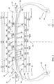
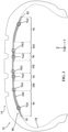
- the tire 10 also comprises a layer 80 of a self-sealing product extending circumferentially radially inside a portion of the internal sealing layer 18 and at least partly in line with the tread 14.
- the self-sealing product is known from the state of the art and may be chosen in particular from the products described in the documents WO2020009849 , WO2011092122 , WO2011092123 .
- the self-sealing product layer is delimited axially by two axial ends 81, 82 arranged respectively at an axial distance less than or equal to 20%, preferably less than or equal to 10% of the axial width of the tread relative to each axial end 41, 42 of the tread 14 respectively. In this case, each axial end 81, 82 is radially aligned respectively with each end 41, 42 even if embodiments in which each axial end 81, 82 is arranged axially inside each axial end 81, 82 will be preferred.
- Each thick axial portion 90 to 96 is axially delimited by two adjacent inflection points such that the thickness of each thick axial portion 90 to 96 increases by moving axially inward of each thick axial portion from each of said inflection points.
- Each thin axial portion 100 to 104 is axially delimited by two adjacent inflection points such that the thickness of said thin axial portion decreases by moving axially inward of each thin axial portion 100 to 104 from each of said inflection points.
- Each thick axial portion 90 to 96 and thin axial portion 100 to 104 extends circumferentially continuously over at least 50%, preferably at least 75% and more preferably over at least 95% and here over 100% of the circumferential length of the layer of self-sealing product 80.
- the average thickness EE1, EE2, EE3, EE4 respectively of each thick axial portion 90, 92, 94, 96 and the average thickness EM1, EM2, EM3 respectively of each thin axial portion 100, 102, 104 is circumferentially substantially constant over at least 50%, preferably over at least 75% and more preferably over at least 95% and here over 100% of the circumferential length of the layer of self-sealing product 80.
- Each thick axial portion 90, 92, 94, 96 respectively comprises an axial portion 90', 92', 94', 96' extending axially in line with each main circumferential cutout 52, 54, 56, 58 respectively.
- Each thick axial portion 90, 92 also respectively comprises an axial portion 90", 92" extending axially in line with the first and second lateral ribs 68, 70.
- Each thin axial portion 100, 102, 104 respectively comprises an axial portion 100', 102', 104' extending axially in line with each central rib 62, 64, 66 respectively.
- Each axial portion 100', 102', 104' is arranged axially between two adjacent axial portions 90' to 96'.
- At least 50% of the values of j ranging from 1 to Q, preferably at least 75% of the values of j ranging from 1 to Q and here for 100% of the values of j ranging from 1 to Q are such that on the one hand, Ec1 ⁇ 1.10 x Ebj and Ec2 ⁇ 1.10 x Ebj, preferably Ec1 ⁇ 1.30 x Ebj and Ec2 ⁇ 1.30 x Ebj and more preferably Ec1 ⁇ 1.50 x Ebj and Ec2 ⁇ 1.50 x Ebj and, on the other hand, Ec1 ⁇ 5.00 x Ebj and Ec2 ⁇ 5.00 x Ebj, preferably Ec1 ⁇ 4.00 x Ebj and Ec2 ⁇ 4.00 x Ebj and more preferably Ec1 ⁇ 2.50 x Ebj and Ec2 ⁇ 2.50 x Ebj.
- Each thick axial portion 90, 92, 94, 96 is at least partly merged with all or part respectively of each axial portion 90', 92', 94', 96'.
- each thick axial portion 90, 92, 94, 96 has an axial width greater than or equal to the axial width respectively of each main circumferential cutout 52, 54, 56, 58.
- each thick axial portion 94, 96 has respectively an axial width W3, W4 such that on the one hand, W3/La3 ⁇ 4.00 and W4/La4 ⁇ 4.00, preferably W3/La3 ⁇ 3.00 W4/La4 ⁇ 3.00, more preferably W3/La3 ⁇ 2.00 and W2/La2 ⁇ 2.00, even more preferably W3/La3 ⁇ 1.50 and W4/La4 ⁇ 1.50 and very preferably W3/La3 ⁇ 1.25 and W4/La4 ⁇ 1.25.
- each thick axial portion 90, 92 is at least partly merged with all or part of each axial portion 90", 92".
- each thick axial portion 90, 92 has an axial width greater than or equal to the axial width respectively of each cutout main circumferential 90", 92".
- each thick axial portion 90, 92 respectively has an axial width W1, W2 such that on the one hand, W1/Lc1 ⁇ 0.50 and W2/Lc2 ⁇ 0.50, preferably W1/Lc1 > 1.00 and W2/Lc2 > 1.00.
- All of the conditions satisfied by the different axial portions 90 to 96, 90' to 96', 90", 92", 100 to 104 and 100' to 104' are satisfied over at least 50%, preferably over at least 75% and more preferably over at least 95% and here over 100% of the circumferential length of the layer of self-sealing product 80.
- Each axial portion 90' to 96', 90", 92" and 100' to 104' of the layer of self-sealing product extending in line with each cutout 52 to 58 and each rib 62 to 70 extends circumferentially continuously over at least 50%, preferably over at least 75% and more preferably over at least 95% and here over 100% of the circumferential length of the layer of self-sealing product 80.
- each axial portion 90' to 96', 90", 92" and 100' to 104' is circumferentially substantially constant over at least 50%, preferably over at least 75% and more preferably over at least 95% and here over 100% of the circumferential length of the layer of self-sealing product 80.
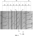
- An extrusion device and a device for applying a strip 200 of the self-sealing product having a width equal to 15 mm and a thickness equal to 0.9 mm are provided.
- Such a device is notably described in WO2015/173120
- a bead of self-sealing product can be used.
- the strip 200 of self-sealing product is wound over several circumferential turns, here over 33 circumferential turns, radially inside the sealing layer 18 of the tire.
- This winding step is conducted according to a law for winding the circumferential turns of the strip 200, the result of which is illustrated in FIG. figure 3 .
- the winding of the strip 200 is started from the axial end 81 and the winding of the strip 200 is stopped when reaching the axial end 82.
- the strip 200 is wound without interrupting the strip 200 between the two axial ends 81, 82.
- the strip 200 is wound on itself a on Nai > 1 circumferential turns radially superimposed on each thick axial portion 90, 92, 94, 96 of the self-sealing product layer 80, i ranging from 1 to 4.
- the strip 200 is wound on itself over Nbj > 1 circumferential turns radially superimposed on each thin axial portion 100, 102, 104 of the self-sealing product layer 80, j ranging from 1 to M.
- At least 50% of the values of j ranging from 1 to M, preferably at least 75% of the values of j ranging from 1 to M and here 100% of the values of j ranging from 1 to M are such that Nbj ⁇ Nai.
- At least 50% of the values of j ranging from 1 to M, preferably at least 75% of the values of j ranging from 1 to M and here 100% of the values of j ranging from 1 to M are such that, on the one hand Nai/Nbj ⁇ 1.20 and, on the other hand, Nai/Nbj ⁇ 3.00, preferably Nai/Nbj ⁇ 2.75 and more preferably Nai/Nbj ⁇ 2.50.
- the winding law includes several parameters for axially varying the thickness of the self-sealing product layer 80. These parameters include a winding pitch of the strip 200, a winding speed of the strip 200 relative to a device for applying the strip 200, a speed of axial movement of the tire 10 relative to a device for applying the strip 200 in the tire 10, an extrusion flow rate of the strip 200 of a device for extruding the strip 200, a width of the strip 200 or a thickness of the strip 200. It is possible to choose to vary only one of these parameters or several simultaneously.
- the winding pitch of the strip 200 has been varied in order to vary axially the thickness of the layer of self-sealing product 80 over at least 50%, preferably over at least 75%, more preferably over at least 95% and here over 100% of the circumferential length of the layer of self-sealing product 80 and to obtain the layer illustrated in the figure 3 .
- each thick axial portion 90 to 96 is completely merged with respectively a part of each axial portion 90' to 96' extending axially in line with respectively each main circumferential cutout 52 to 58.
- each axial portion 100', 102', 104' extending axially at the right of each central rib 62, 64, 66 respectively has a zero thickness of self-sealing product.
- Each axial portion 100', 102', 104' is arranged axially between two of the axially adjacent axial portions 90' to 96' and also axially between the two axial portions 90" and 92".
- the thickness of the strip 200 which is substantially zero between the axially adjacent axial portions 90' to 96', is varied not by the laying pitch.
- the strip 200 is wound by interrupting the strip 200, here three times, between the two axial ends 81, 82.
- each central rib 62, 64, 66 is devoid of any transverse cutout. In this case, it would be said that each central rib 62, 64, 66 is uncut.
Landscapes
- Engineering & Computer Science (AREA)
- Mechanical Engineering (AREA)
- Tires In General (AREA)
Claims (15)
- Reifen (10), welcher umfasst:- einen Laufstreifen (14), welcher umfasst:- mindestens eine Rippe (68, 70), tief ausgeschnittene Rippe genannt, die mindestens einen quer verlaufenden Ausschnitt (77, 78) umfasst, der eine solche Tiefe Ht aufweist, dass Ht/Hs ≥ 50 % ist, wobei Hs die Profiltiefe ist,- mindestens eine Rippe (62, 64, 66), nicht oder wenig ausgeschnittene Rippe genannt, die nicht mit quer verlaufenden Ausschnitten versehen ist oder quer verlaufende Ausschnitte (71, 72, 73) umfasst, die jeweils, für mindestens 50 %, vorzugsweise für mindestens 75 % und stärker bevorzugt für 100 % der Anzahl quer verlaufender Ausschnitte (71, 72, 73) der oder jeder wenig ausgeschnittenen Rippe (62, 64, 66), mindestens eine der folgenden Bedingungen erfüllen:- Der quer verlaufende Ausschnitt (71, 72, 73) der wenig ausgeschnittenen Rippe (62, 64, 66) weist eine Breite auf, die streng kleiner als 1,6 mm ist,- der quer verlaufende Ausschnitt (71, 72, 73) der wenig ausgeschnittenen Rippe (62, 64, 66) weist eine solche Tiefe H auf, dass H/Hs < 50 % ist,- eine innere Dichtungsschicht (18),- eine Schicht eines selbstdichtenden Produkts (80), die sich radial innerhalb eines Teils der inneren Dichtungsschicht (18) in Umfangsrichtung erstreckt, dadurch gekennzeichnet, dass die Schicht aus selbstdichtendem Produkt (80) auf mindestens 50 % der Umfangslänge der Schicht aus selbstdichtendem Produkt (80) umfasst:- einen axialen Abschnitt (90", 92"), der sich an der tief ausgeschnittenen Rippe (68, 70) axial erstreckt und eine mittlere Dicke Ec > 0 des selbstdichtenden Produkts aufweist,- einen axialen Abschnitt (100', 102', 104'), der sich an der nicht oder wenig ausgeschnittenen Rippe (62, 64, 66) axial erstreckt und eine solche mittlere Dicke Eb ≥ 0 des selbstdichtenden Produkts aufweist, dass Eb < Ec ist.
- Reifen (10) nach dem vorhergehenden Anspruch, wobei jede tief ausgeschnittene Rippe (68, 70) und jede nicht oder wenig ausgeschnittene Rippe (62, 64, 66) axial von einem axial inneren Ende und von einem axial äußeren Ende begrenzt wird, wobei jedes axial innere und äußere ausgewählt ist aus:- einem axialen Ende (41, 42) des Laufstreifens (14) und- einem axial inneren oder äußeren Ende (521, 522, 541, 542, 561, 562, 581, 582) eines umlaufenden Ausschnitts (52, 54, 56, 58), umlaufender Hauptausschnitt genannt, der eine solche Tiefe Ha aufweist, dass Ha/Hs ≥ 50 %, vorzugsweise Ha/Hs ≥ 75 % und stärker bevorzugt Ha/Hs ≥ 90 %ist,wobei das axial innere und äußere Ende der Rippe (62, 64, 66, 68, 70) einander benachbarte Enden sind.
- Reifen (10) nach einem der vorhergehenden Ansprüche, wobei Ec ≥ 1,10 x Eb, vorzugsweise Ec ≥ 1,30 x Eb und stärker bevorzugt Ec ≥ 1,50 x Eb ist.
- Reifen (10) nach einem der vorhergehenden Ansprüche, wobei Ec ≤ 5,00 x Eb, vorzugsweise Ec ≤ 4,00 x Eb und stärker bevorzugt Ec ≤ 2,50 x Eb ist.
- Reifen (10) nach einem der vorhergehenden Ansprüche, wobei die Schicht aus selbstdichtendem Produkt (80) mindestens einen axialen Abschnitt umfasst, dicker axialer Abschnitt (90, 92) genannt, wobei der oder jeder dicke axiale Abschnitt (90, 92) wenigstens teilweise mit dem gesamten oder einem Teil des oder jedes axialen Abschnitts (90", 92") zusammenfällt, der sich axial an der oder jeder tief ausgeschnittenen Rippe (68, 70) erstreckt, wobei der oder jeder dicke axiale Abschnitt (90, 92) axial von zwei benachbarten Wendepunkten (81, 82, 83, 88) der radial inneren Oberflächenkurve (89) der Schicht aus selbstdichtendem Produkt (80) begrenzt wird, wobei die Dicke des dicken axialen Abschnitts (90, 92) von jedem der Wendepunkt aus, wenn man sich axial zum Inneren des dicken axialen Abschnitts hin bewegt, zunimmt, wobei die axiale Breite Wy des dicken axialen Abschnitts (90, 92) so beschaffen ist, dass Wy/Lcy ≥ 0,50, vorzugsweise Wy/Lcy > 1,00 ist, wobei Lcy die axiale Breite der tief ausgeschnittenen Rippe (68, 70) ist.
- Reifen (10) nach einem der vorhergehenden Ansprüche, wobei der oder jeder quer verlaufende Ausschnitt (77, 78) der oder jeder tief ausgeschnittenen Rippe (68, 70) eine Breite aufweist, die größer oder gleich 0,7 mm, vorzugsweise größer oder gleich 1,0 mm und stärker bevorzugt größer oder gleich 1,6 mm ist.
- Reifen (10) nach einem der vorhergehenden Ansprüche, wobei der oder jeder quer verlaufende Ausschnitt (77, 78) der oder jeder tief ausgeschnittenen Rippe (68, 70) eine Tiefe aufweist, die zwischen 2,0 mm und der Profiltiefe, vorzugsweise zwischen 4,0 mm und der Profiltiefe und stärker bevorzugt zwischen 5,0 mm und der Profiltiefe liegt.
- Reifen (10) nach einem der vorhergehenden Ansprüche, wobei jedes axiale Ende (81, 82) der Schicht aus selbstdichtendem Produkt (80) in einem axialen Abstand, der kleiner oder gleich 20 %, vorzugsweise kleiner oder gleich 10 % der axialen Breite des Laufstreifens (14) ist, in Bezug auf das jeweilige axiale Ende (41, 42) des Laufstreifens (14) angeordnet ist, vorzugsweise axial innerhalb des jeweiligen axialen Endes (41, 42) des Laufstreifens (14).
- Reifen (10) nach einem der vorhergehenden Ansprüche, wobei der Laufstreifen (14) umfasst:- einen axial mittleren Abschnitt (P0), welcher umfasst:- zwei umlaufende Hauptausschnitte (52, 54), welche die axial äußersten sind, axial beiderseits der Mittelebene (M) des Reifens angeordnet sind und eine solche Tiefe Ha1 bzw. Ha2 aufweisen, dass Ha1/Hs ≥ 50 % und Ha2/Hs ≥50 %, vorzugsweise Ha1/Hs ≥ 75 % und Ha2/Hs ≥ 75 % und stärker bevorzugt Ha1/Hs ≥ 90 % und Ha2/Hs ≥ 90 % ist,- die oder jede nicht oder wenig ausgeschnittene Rippe (62, 64, 66),- einen ersten und einen zweiten axial seitlichen Abschnitt (P1, P2), die axial außerhalb des axial mittleren Abschnitts (P0) axial beiderseits des axial mittleren Abschnitts (P0) in Bezug auf die Mittelebene (M) des Reifens (10) angeordnet sind, wobei der erste und zweite axial seitliche Abschnitt (P1, P2) sich jeweils axial vom jeweiligen axialen Ende (41, 42) des Laufstreifens (14) aus bis zum jeweiligen axial äußeren Ende (521, 541) des jeweiligen axial äußersten umlaufenden Hauptausschnitts (52, 54) erstrecken, wobei der erste und/oder der zweite axial seitliche Abschnitt (P1, P2) eine tief ausgeschnittene Rippe (68, 70) umfassen.
- Reifen (10) nach dem vorhergehenden Anspruch, wobei der erste und der zweite axial seitliche Abschnitt (P1, P2) eine erste bzw. eine zweite tief ausgeschnittene Rippe (68, 70) umfassen.
- Reifen (10) nach einem der vorhergehenden Ansprüche, wobeider Laufstreifen (14) umfasst:- P > 1 tief ausgeschnittene Rippen (68, 70), die jeweils mindestens einen quer verlaufenden Ausschnitt (77, 78) umfassen, der eine solche Tiefe Ht aufweist, dass Ht/Hs ≥ 50 %, vorzugsweise Ht/Hs ≥ 75 %, stärker bevorzugt Ht/Hs ≥ 90 % ist, wobei Hs die Profiltiefe ist und P die Gesamtzahl tief ausgeschnittener Rippen ist, die auf dem Reifen vorhanden sind,- Q ≥ 1 nicht oder wenig ausgeschnittene Rippe(n) (62, 64, 66), die nicht mit quer verlaufenden Ausschnitten versehen ist (sind) oder quer verlaufende Ausschnitte (71, 72, 73) umfasst (umfassen), die jeweils, für mindestens 50 %, vorzugsweise für mindestens 75 % und stärker bevorzugt für 100 % der Anzahl quer verlaufender Ausschnitte (71, 72, 73) der oder jeder wenig ausgeschnittenen Rippe (62, 64, 66), mindestens eine der folgenden Bedingungen erfüllen:- Der quer verlaufende Ausschnitt (71, 72, 73) der nicht oder wenig ausgeschnittenen Rippe (62, 64, 66) weist eine Breite auf, die streng kleiner als 1,6 mm, vorzugsweise streng kleiner als 1,0 mm und stärker bevorzugt streng kleiner als 0,7 mm ist,- der quer verlaufende Ausschnitt (71, 72, 73) der nicht oder wenig ausgeschnittenen Rippe (62, 64, 66) weist eine solche Tiefe H auf, dass H/Hs < 50 %, vorzugsweise H/Hs < 30 % ist,wobei Q die Gesamtzahl nicht oder wenig ausgeschnittener Rippen ist, die auf dem Reifen vorhanden sind,wobei die Schicht aus selbstdichtendem Produkt (80) umfasst:- P > 1 axiale Abschnitte (90", 92"), die sich jeweils axial an einer der N tief ausgeschnittenen Rippen (68, 70) erstrecken und jeweils eine mittlere Dicke Eck > 0 des selbstdichtenden Produkts aufweisen,- Q ≥ 1 axiale(n) Abschnitt(e) (100', 102', 104'), die sich jeweils axial an der oder einer der Q nicht oder wenig ausgeschnittene(n) Rippe(n) (62, 64, 66) erstrecken und jeweils eine mittlere Dicke Ebj ≥ 0 des selbstdichtenden Produkts aufweisen, für j von 1 bis Q, und axial zwischen zwei benachbarten axialen Abschnitten (90", 92") der Schicht aus selbstdichtendem Produkt (80) angeordnet sind, die sich axial an zwei der P tief ausgeschnittenen Rippen (68, 70) erstrecken, und derart, dass für jeden Wert von k von 1 bis P für mindestens 50 % der Werte von j von 1 bis Q, vorzugsweise mindestens 75 % der Werte von j von 1 bis Q und stärker bevorzugt 100 % der Werte von j von 1 bis Q gilt, dass Ebj < Eck ist.
- Reifen (10) nach dem vorhergehenden Anspruch, wobei der Laufstreifen (14) N=Q+1 > 1 umlaufende Hauptausschnitte (52, 54, 56, 58) umfasst, die jeweils eine solche Tiefe Hai aufweisen, dass Hai/Hs ≥ 50 %, vorzugsweise Hai/Hs ≥ 75 % und stärker bevorzugt Hai/Hs ≥ 90 % ist, für i von 1 bis N, wobei N die Gesamtzahl umlaufender Hauptausschnitte ist, die auf dem Reifen vorhanden sind, wobei die oder jede nicht oder wenig ausgeschnittene Rippe (62, 64, 66) axial zwischen zwei benachbarten umlaufenden Hauptausschnitten (52, 54, 56, 58) angeordnet ist und axial von diesen zwei benachbarten umlaufenden Hauptausschnitten (52, 54, 56, 58) begrenzt wird,
wobei die Schicht aus selbstdichtendem Produkt (80) N > 1 axiale Abschnitte (90', 92', 94', 96') umfasst, die sich jeweils axial an einem der N umlaufenden Hauptausschnitte (52, 54, 56, 58) erstrecken und jeweils eine solche mittlere Dicke Eai > 0 von selbstdichtendem Produkt aufweisen, dass für jeden Wert von i von 1 bis N für mindestens 50 % der Werte von j von 1 bis Q, vorzugsweise mindestens 75 % der Werte von j von 1 bis Q und stärker bevorzugt 100 % der Werte von j von 1 bis Q gilt, dass Ebj < Eai ist. - Reifen (10) nach dem vorhergehenden Anspruch, wobei der oder jeder umlaufende Hauptausschnitt (52, 54, 56, 58) eine axiale Breite aufweist, die größer oder gleich 1,0 mm, vorzugsweise größer oder gleich 5,0 mm und stärker bevorzugt größer oder gleich 8,0 mm ist und noch stärker bevorzugt 8,0 bis 20,0 mm beträgt.
- Reifen (10) nach Anspruch 12 oder 13, wobei der oder jeder umlaufende Hauptausschnitt (52, 54, 56, 58) eine Tiefe aufweist, die zwischen 4,0 mm und der Profiltiefe, vorzugsweise zwischen 5,0 mm und der Profiltiefe und stärker bevorzugt zwischen 5,5 mm und der Profiltiefe liegt.
- Reifen (10) nach einem der Ansprüche 12 bis 14, wobei die Schicht aus selbstdichtendem Produkt (80) mindestens einen axialen Abschnitt (90, 92, 94, 96) umfasst, dicker axialer Abschnitt genannt, wobei der oder jeder dicke axiale Abschnitt (90, 92, 94, 96) wenigstens teilweise mit dem gesamten oder einem Teil des oder jedes axialen Abschnitts (90', 92', 94', 96') zusammenfällt, der sich axial an dem oder jedem umlaufenden Hauptausschnitt (52, 54, 56, 58) erstreckt, wobei der oder jeder dicke axiale Abschnitt (90, 92, 94, 96) von zwei benachbarten Wendepunkten (81, 82, 83, 84, 85, 86, 87, 88) der radial inneren Oberflächenkurve (89) der Schicht aus selbstdichtendem Produkt (80) begrenzt wird, wobei die Dicke des dicken axialen Abschnitts (90, 92, 94, 96) von jedem der Wendepunkt aus, wenn man sich axial zum Inneren des dicken axialen Abschnitts (90, 92, 94, 96) hin bewegt, zunimmt, wobei die axiale Breite Wx des dicken axialen Abschnitts (90, 92, 94, 96) so beschaffen ist, dass Wx/Lcx ≥ 0,50, vorzugsweise Wx/Lcx > 1,00 ist, wobei Lcx die axiale Breite des umlaufenden Hauptausschnitts (52, 54, 56, 58) ist.
Applications Claiming Priority (2)
| Application Number | Priority Date | Filing Date | Title |
|---|---|---|---|
| FR2009908 | 2020-09-29 | ||
| PCT/FR2021/051647 WO2022069820A1 (fr) | 2020-09-29 | 2021-09-24 | Pneumatique comprenant une couche de produit auto-obturant optimisée |
Publications (2)
| Publication Number | Publication Date |
|---|---|
| EP4222003A1 EP4222003A1 (de) | 2023-08-09 |
| EP4222003B1 true EP4222003B1 (de) | 2024-11-06 |
Family
ID=73699034
Family Applications (1)
| Application Number | Title | Priority Date | Filing Date |
|---|---|---|---|
| EP21798067.1A Active EP4222003B1 (de) | 2020-09-29 | 2021-09-24 | Reifen mit einer optimierten schicht aus selbstdichtendem produkt |
Country Status (6)
| Country | Link |
|---|---|
| US (1) | US20230311590A1 (de) |
| EP (1) | EP4222003B1 (de) |
| JP (1) | JP7787884B2 (de) |
| KR (1) | KR20230075437A (de) |
| CN (1) | CN116323259B (de) |
| WO (1) | WO2022069820A1 (de) |
Families Citing this family (1)
| Publication number | Priority date | Publication date | Assignee | Title |
|---|---|---|---|---|
| CN116261513A (zh) | 2020-09-29 | 2023-06-13 | 米其林集团总公司 | 制造优化的自密封产品层的方法 |
Family Cites Families (24)
| Publication number | Priority date | Publication date | Assignee | Title |
|---|---|---|---|---|
| US4113799A (en) | 1975-07-14 | 1978-09-12 | Rocket Research Corp. | Elastomeric sealant composition |
| US4115172A (en) | 1977-04-04 | 1978-09-19 | Uniroyal, Inc. | Apparatus and method for applying puncture sealant material to a tire |
| US4426468A (en) | 1978-10-10 | 1984-01-17 | Rockcor, Inc. | Sealant composition |
| US4913209A (en) | 1985-01-22 | 1990-04-03 | The Uniroyal Goodrich Tire Company | Sealant product, laminate thereof, and pneumatic tire constructed therewith |
| US5085942A (en) | 1985-01-22 | 1992-02-04 | The Uniroyal Goodrich Tire Company | Sealant product, laminate thereof, and pneumatic tire constructed therewith |
| US5295525A (en) | 1992-06-22 | 1994-03-22 | Michelin Recherche Et Technique S.A. | Puncture sealant formulation |
| JPH0655913A (ja) * | 1992-08-07 | 1994-03-01 | Bridgestone Corp | 空気入りタイヤ |
| ID26585A (id) * | 1998-03-16 | 2001-01-18 | Honda Motor Co Ltd | Metode pembuatan ban yang disatukan perapat dan ban yang disatukan perapat |
| KR100277523B1 (ko) | 1998-05-30 | 2001-01-15 | 김호균 | 타이어 펑크방지 조성물 및 그 도포방법 |
| FR2894183B1 (fr) * | 2005-12-06 | 2008-02-15 | Michelin Soc Tech | Bande de roulement pour pneumatique poids lourd |
| FR2917996B1 (fr) | 2007-06-28 | 2009-08-21 | Michelin Soc Tech | Pneumatique avec une couche auto-obturante. |
| JP4992937B2 (ja) * | 2009-05-25 | 2012-08-08 | 横浜ゴム株式会社 | 空気入りタイヤ |
| FR2955581B1 (fr) | 2010-01-28 | 2012-02-17 | Michelin Soc Tech | Procede de fabrication d'une composition d'elastomere a propriete auto-obturante |
| FR2955587B1 (fr) | 2010-01-28 | 2012-02-17 | Michelin Soc Tech | Composition d'elastomere pour objet pneumatique, a propriete auto-obturante |
| FR2966081B1 (fr) | 2010-10-18 | 2012-12-14 | Michelin Soc Tech | Bandage pneumatique comprenant une couche auto-obturante a gradient radial de fluage |
| WO2015016051A1 (ja) * | 2013-07-30 | 2015-02-05 | 住友ゴム工業株式会社 | 重荷重用タイヤ |
| KR101497839B1 (ko) * | 2013-11-12 | 2015-03-02 | 한국타이어 주식회사 | 다층 실런트 구조를 포함하는 공기입 타이어 |
| FR3020982B1 (fr) | 2014-05-13 | 2016-06-24 | Michelin & Cie | Procede de pose d'un produit auto-obturant sur la surface interne d'un pneumatique |
| US10399391B2 (en) * | 2014-12-16 | 2019-09-03 | Triangle Tyre Co., Ltd. | Pneumatic tire having multiple built-in sealant layers and preparation thereof |
| JP2016221991A (ja) * | 2015-05-27 | 2016-12-28 | 横浜ゴム株式会社 | 空気入りタイヤ |
| JP6668782B2 (ja) * | 2016-01-26 | 2020-03-18 | 住友ゴム工業株式会社 | タイヤ |
| DE102016212472A1 (de) * | 2016-07-08 | 2018-01-11 | Continental Reifen Deutschland Gmbh | Fahrzeugluftreifen |
| WO2020009849A1 (en) | 2018-07-03 | 2020-01-09 | Corning Incorporated | Selective masking and plugging of honeycomb bodies |
| CN111016549A (zh) * | 2019-12-31 | 2020-04-17 | 江苏通用科技股份有限公司 | 一种抗刺扎自修复免修补静音轮胎及加工方法 |
-
2021
- 2021-09-24 US US18/029,331 patent/US20230311590A1/en active Pending
- 2021-09-24 WO PCT/FR2021/051647 patent/WO2022069820A1/fr not_active Ceased
- 2021-09-24 CN CN202180065507.3A patent/CN116323259B/zh active Active
- 2021-09-24 KR KR1020237010170A patent/KR20230075437A/ko active Pending
- 2021-09-24 JP JP2023519680A patent/JP7787884B2/ja active Active
- 2021-09-24 EP EP21798067.1A patent/EP4222003B1/de active Active
Also Published As
| Publication number | Publication date |
|---|---|
| JP7787884B2 (ja) | 2025-12-17 |
| KR20230075437A (ko) | 2023-05-31 |
| CN116323259B (zh) | 2025-07-04 |
| WO2022069820A1 (fr) | 2022-04-07 |
| US20230311590A1 (en) | 2023-10-05 |
| CN116323259A (zh) | 2023-06-23 |
| JP2023542742A (ja) | 2023-10-11 |
| EP4222003A1 (de) | 2023-08-09 |
Similar Documents
| Publication | Publication Date | Title |
|---|---|---|
| EP4222002A1 (de) | Reifen mit einer optimierten selbstdichtenden produktschicht | |
| EP4164898B1 (de) | Geräuscharmer reifen | |
| EP3368350B1 (de) | Luftreifen mit arbeitsschichten mit monofilamenten und reifenprofil mit nuten | |
| EP3589503B1 (de) | Reifenlauffläche für einen lkw-anhänger | |
| WO2022069822A1 (fr) | Pneumatique comprenant une couche additionnelle pour réduire le bruit extérieur | |
| EP4149773B1 (de) | Reifen mit verbesserter griffigkeit am ende der lebensdauer auf nassem boden | |
| EP3946973B1 (de) | Reifen mit arbeitsschichten mit optimierter architektur und laufflächengestaltung | |
| EP4222003B1 (de) | Reifen mit einer optimierten schicht aus selbstdichtendem produkt | |
| WO2023194020A1 (fr) | Pneumatique adapté pour un roulage à plat et comprenant une couche de sommet ondulée | |
| EP4221967B1 (de) | Verfahren zur herstellung einer optimierten schicht eines selbstdichtenden produkts | |
| EP3368338B1 (de) | Luftreifen mit arbeitsschichten aus monofilamenten und einer reifenlauffläche mit rillen | |
| EP4096938B1 (de) | Motorradreifen | |
| EP4366958B1 (de) | Reifen mit hybriden quereinschnitten | |
| EP3368348B1 (de) | Luftreifen mit arbeitsschichten aus monofilamenten und einer reifenlauffläche mit rillen | |
| EP3642051B1 (de) | Reifenartige vorrichtung für ein fahrzeug | |
| EP3691920B1 (de) | Reifen mit einschnitten im wulstbereich | |
| FR3140795A1 (fr) | Pneumatique comprenant des pains comprenant des incisions allongées | |
| WO2023194018A1 (fr) | Pneumatique comprenant une couche de sommet ondulée et un insert de rigidification de flanc | |
| FR3140794A1 (fr) | Pneumatique comprenant une bande de roulement souple | |
| WO2026002603A1 (fr) | Pneumatique présentant un agencement d'armature de frettage optimisé |
Legal Events
| Date | Code | Title | Description |
|---|---|---|---|
| STAA | Information on the status of an ep patent application or granted ep patent |
Free format text: STATUS: UNKNOWN |
|
| STAA | Information on the status of an ep patent application or granted ep patent |
Free format text: STATUS: THE INTERNATIONAL PUBLICATION HAS BEEN MADE |
|
| PUAI | Public reference made under article 153(3) epc to a published international application that has entered the european phase |
Free format text: ORIGINAL CODE: 0009012 |
|
| STAA | Information on the status of an ep patent application or granted ep patent |
Free format text: STATUS: REQUEST FOR EXAMINATION WAS MADE |
|
| 17P | Request for examination filed |
Effective date: 20230502 |
|
| AK | Designated contracting states |
Kind code of ref document: A1 Designated state(s): AL AT BE BG CH CY CZ DE DK EE ES FI FR GB GR HR HU IE IS IT LI LT LU LV MC MK MT NL NO PL PT RO RS SE SI SK SM TR |
|
| DAV | Request for validation of the european patent (deleted) | ||
| DAX | Request for extension of the european patent (deleted) | ||
| GRAP | Despatch of communication of intention to grant a patent |
Free format text: ORIGINAL CODE: EPIDOSNIGR1 |
|
| STAA | Information on the status of an ep patent application or granted ep patent |
Free format text: STATUS: GRANT OF PATENT IS INTENDED |
|
| INTG | Intention to grant announced |
Effective date: 20240528 |
|
| GRAS | Grant fee paid |
Free format text: ORIGINAL CODE: EPIDOSNIGR3 |
|
| GRAA | (expected) grant |
Free format text: ORIGINAL CODE: 0009210 |
|
| STAA | Information on the status of an ep patent application or granted ep patent |
Free format text: STATUS: THE PATENT HAS BEEN GRANTED |
|
| AK | Designated contracting states |
Kind code of ref document: B1 Designated state(s): AL AT BE BG CH CY CZ DE DK EE ES FI FR GB GR HR HU IE IS IT LI LT LU LV MC MK MT NL NO PL PT RO RS SE SI SK SM TR |
|
| REG | Reference to a national code |
Ref country code: GB Ref legal event code: FG4D Free format text: NOT ENGLISH |
|
| REG | Reference to a national code |
Ref country code: CH Ref legal event code: EP |
|
| REG | Reference to a national code |
Ref country code: DE Ref legal event code: R096 Ref document number: 602021021542 Country of ref document: DE |
|
| REG | Reference to a national code |
Ref country code: IE Ref legal event code: FG4D Free format text: LANGUAGE OF EP DOCUMENT: FRENCH |
|
| REG | Reference to a national code |
Ref country code: LT Ref legal event code: MG9D |
|
| REG | Reference to a national code |
Ref country code: NL Ref legal event code: MP Effective date: 20241106 |
|
| PG25 | Lapsed in a contracting state [announced via postgrant information from national office to epo] |
Ref country code: IS Free format text: LAPSE BECAUSE OF FAILURE TO SUBMIT A TRANSLATION OF THE DESCRIPTION OR TO PAY THE FEE WITHIN THE PRESCRIBED TIME-LIMIT Effective date: 20250306 Ref country code: HR Free format text: LAPSE BECAUSE OF FAILURE TO SUBMIT A TRANSLATION OF THE DESCRIPTION OR TO PAY THE FEE WITHIN THE PRESCRIBED TIME-LIMIT Effective date: 20241106 Ref country code: PT Free format text: LAPSE BECAUSE OF FAILURE TO SUBMIT A TRANSLATION OF THE DESCRIPTION OR TO PAY THE FEE WITHIN THE PRESCRIBED TIME-LIMIT Effective date: 20250306 |
|
| PG25 | Lapsed in a contracting state [announced via postgrant information from national office to epo] |
Ref country code: FI Free format text: LAPSE BECAUSE OF FAILURE TO SUBMIT A TRANSLATION OF THE DESCRIPTION OR TO PAY THE FEE WITHIN THE PRESCRIBED TIME-LIMIT Effective date: 20241106 Ref country code: NL Free format text: LAPSE BECAUSE OF FAILURE TO SUBMIT A TRANSLATION OF THE DESCRIPTION OR TO PAY THE FEE WITHIN THE PRESCRIBED TIME-LIMIT Effective date: 20241106 |
|
| REG | Reference to a national code |
Ref country code: AT Ref legal event code: MK05 Ref document number: 1739008 Country of ref document: AT Kind code of ref document: T Effective date: 20241106 |
|
| PG25 | Lapsed in a contracting state [announced via postgrant information from national office to epo] |
Ref country code: BG Free format text: LAPSE BECAUSE OF FAILURE TO SUBMIT A TRANSLATION OF THE DESCRIPTION OR TO PAY THE FEE WITHIN THE PRESCRIBED TIME-LIMIT Effective date: 20241106 |
|
| PG25 | Lapsed in a contracting state [announced via postgrant information from national office to epo] |
Ref country code: ES Free format text: LAPSE BECAUSE OF FAILURE TO SUBMIT A TRANSLATION OF THE DESCRIPTION OR TO PAY THE FEE WITHIN THE PRESCRIBED TIME-LIMIT Effective date: 20241106 |
|
| PG25 | Lapsed in a contracting state [announced via postgrant information from national office to epo] |
Ref country code: NO Free format text: LAPSE BECAUSE OF FAILURE TO SUBMIT A TRANSLATION OF THE DESCRIPTION OR TO PAY THE FEE WITHIN THE PRESCRIBED TIME-LIMIT Effective date: 20250206 |
|
| PG25 | Lapsed in a contracting state [announced via postgrant information from national office to epo] |
Ref country code: AT Free format text: LAPSE BECAUSE OF FAILURE TO SUBMIT A TRANSLATION OF THE DESCRIPTION OR TO PAY THE FEE WITHIN THE PRESCRIBED TIME-LIMIT Effective date: 20241106 Ref country code: LV Free format text: LAPSE BECAUSE OF FAILURE TO SUBMIT A TRANSLATION OF THE DESCRIPTION OR TO PAY THE FEE WITHIN THE PRESCRIBED TIME-LIMIT Effective date: 20241106 Ref country code: GR Free format text: LAPSE BECAUSE OF FAILURE TO SUBMIT A TRANSLATION OF THE DESCRIPTION OR TO PAY THE FEE WITHIN THE PRESCRIBED TIME-LIMIT Effective date: 20250207 |
|
| PG25 | Lapsed in a contracting state [announced via postgrant information from national office to epo] |
Ref country code: PL Free format text: LAPSE BECAUSE OF FAILURE TO SUBMIT A TRANSLATION OF THE DESCRIPTION OR TO PAY THE FEE WITHIN THE PRESCRIBED TIME-LIMIT Effective date: 20241106 |
|
| PG25 | Lapsed in a contracting state [announced via postgrant information from national office to epo] |
Ref country code: RS Free format text: LAPSE BECAUSE OF FAILURE TO SUBMIT A TRANSLATION OF THE DESCRIPTION OR TO PAY THE FEE WITHIN THE PRESCRIBED TIME-LIMIT Effective date: 20250206 |
|
| PG25 | Lapsed in a contracting state [announced via postgrant information from national office to epo] |
Ref country code: SM Free format text: LAPSE BECAUSE OF FAILURE TO SUBMIT A TRANSLATION OF THE DESCRIPTION OR TO PAY THE FEE WITHIN THE PRESCRIBED TIME-LIMIT Effective date: 20241106 |
|
| PG25 | Lapsed in a contracting state [announced via postgrant information from national office to epo] |
Ref country code: DK Free format text: LAPSE BECAUSE OF FAILURE TO SUBMIT A TRANSLATION OF THE DESCRIPTION OR TO PAY THE FEE WITHIN THE PRESCRIBED TIME-LIMIT Effective date: 20241106 |
|
| PG25 | Lapsed in a contracting state [announced via postgrant information from national office to epo] |
Ref country code: EE Free format text: LAPSE BECAUSE OF FAILURE TO SUBMIT A TRANSLATION OF THE DESCRIPTION OR TO PAY THE FEE WITHIN THE PRESCRIBED TIME-LIMIT Effective date: 20241106 |
|
| PG25 | Lapsed in a contracting state [announced via postgrant information from national office to epo] |
Ref country code: RO Free format text: LAPSE BECAUSE OF FAILURE TO SUBMIT A TRANSLATION OF THE DESCRIPTION OR TO PAY THE FEE WITHIN THE PRESCRIBED TIME-LIMIT Effective date: 20241106 |
|
| PG25 | Lapsed in a contracting state [announced via postgrant information from national office to epo] |
Ref country code: SK Free format text: LAPSE BECAUSE OF FAILURE TO SUBMIT A TRANSLATION OF THE DESCRIPTION OR TO PAY THE FEE WITHIN THE PRESCRIBED TIME-LIMIT Effective date: 20241106 |
|
| PG25 | Lapsed in a contracting state [announced via postgrant information from national office to epo] |
Ref country code: CZ Free format text: LAPSE BECAUSE OF FAILURE TO SUBMIT A TRANSLATION OF THE DESCRIPTION OR TO PAY THE FEE WITHIN THE PRESCRIBED TIME-LIMIT Effective date: 20241106 |
|
| PG25 | Lapsed in a contracting state [announced via postgrant information from national office to epo] |
Ref country code: IT Free format text: LAPSE BECAUSE OF FAILURE TO SUBMIT A TRANSLATION OF THE DESCRIPTION OR TO PAY THE FEE WITHIN THE PRESCRIBED TIME-LIMIT Effective date: 20241106 |
|
| REG | Reference to a national code |
Ref country code: DE Ref legal event code: R097 Ref document number: 602021021542 Country of ref document: DE |
|
| PG25 | Lapsed in a contracting state [announced via postgrant information from national office to epo] |
Ref country code: SE Free format text: LAPSE BECAUSE OF FAILURE TO SUBMIT A TRANSLATION OF THE DESCRIPTION OR TO PAY THE FEE WITHIN THE PRESCRIBED TIME-LIMIT Effective date: 20241106 |
|
| PLBE | No opposition filed within time limit |
Free format text: ORIGINAL CODE: 0009261 |
|
| STAA | Information on the status of an ep patent application or granted ep patent |
Free format text: STATUS: NO OPPOSITION FILED WITHIN TIME LIMIT |
|
| PGFP | Annual fee paid to national office [announced via postgrant information from national office to epo] |
Ref country code: DE Payment date: 20250919 Year of fee payment: 5 |
|
| 26N | No opposition filed |
Effective date: 20250807 |
|
| PGFP | Annual fee paid to national office [announced via postgrant information from national office to epo] |
Ref country code: FR Payment date: 20250922 Year of fee payment: 5 |