EP4096938B1 - Motorradreifen - Google Patents
Motorradreifen Download PDFInfo
- Publication number
- EP4096938B1 EP4096938B1 EP20828049.5A EP20828049A EP4096938B1 EP 4096938 B1 EP4096938 B1 EP 4096938B1 EP 20828049 A EP20828049 A EP 20828049A EP 4096938 B1 EP4096938 B1 EP 4096938B1
- Authority
- EP
- European Patent Office
- Prior art keywords
- carcass
- crown
- assembly
- angle
- filamentary
- Prior art date
- Legal status (The legal status is an assumption and is not a legal conclusion. Google has not performed a legal analysis and makes no representation as to the accuracy of the status listed.)
- Active
Links
Images


Classifications
-
- B—PERFORMING OPERATIONS; TRANSPORTING
- B60—VEHICLES IN GENERAL
- B60C—VEHICLE TYRES; TYRE INFLATION; TYRE CHANGING; CONNECTING VALVES TO INFLATABLE ELASTIC BODIES IN GENERAL; DEVICES OR ARRANGEMENTS RELATED TO TYRES
- B60C9/00—Reinforcements or ply arrangement of pneumatic tyres
- B60C9/02—Carcasses
- B60C9/04—Carcasses the reinforcing cords of each carcass ply arranged in a substantially parallel relationship
-
- B—PERFORMING OPERATIONS; TRANSPORTING
- B60—VEHICLES IN GENERAL
- B60C—VEHICLE TYRES; TYRE INFLATION; TYRE CHANGING; CONNECTING VALVES TO INFLATABLE ELASTIC BODIES IN GENERAL; DEVICES OR ARRANGEMENTS RELATED TO TYRES
- B60C9/00—Reinforcements or ply arrangement of pneumatic tyres
- B60C9/18—Structure or arrangement of belts or breakers, crown-reinforcing or cushioning layers
- B60C9/20—Structure or arrangement of belts or breakers, crown-reinforcing or cushioning layers built-up from rubberised plies each having all cords arranged substantially parallel
- B60C2009/2012—Structure or arrangement of belts or breakers, crown-reinforcing or cushioning layers built-up from rubberised plies each having all cords arranged substantially parallel with particular configuration of the belt cords in the respective belt layers
- B60C2009/2016—Structure or arrangement of belts or breakers, crown-reinforcing or cushioning layers built-up from rubberised plies each having all cords arranged substantially parallel with particular configuration of the belt cords in the respective belt layers comprising cords at an angle of 10 to 30 degrees to the circumferential direction
-
- B—PERFORMING OPERATIONS; TRANSPORTING
- B60—VEHICLES IN GENERAL
- B60C—VEHICLE TYRES; TYRE INFLATION; TYRE CHANGING; CONNECTING VALVES TO INFLATABLE ELASTIC BODIES IN GENERAL; DEVICES OR ARRANGEMENTS RELATED TO TYRES
- B60C9/00—Reinforcements or ply arrangement of pneumatic tyres
- B60C9/18—Structure or arrangement of belts or breakers, crown-reinforcing or cushioning layers
- B60C9/20—Structure or arrangement of belts or breakers, crown-reinforcing or cushioning layers built-up from rubberised plies each having all cords arranged substantially parallel
- B60C2009/2012—Structure or arrangement of belts or breakers, crown-reinforcing or cushioning layers built-up from rubberised plies each having all cords arranged substantially parallel with particular configuration of the belt cords in the respective belt layers
- B60C2009/2019—Structure or arrangement of belts or breakers, crown-reinforcing or cushioning layers built-up from rubberised plies each having all cords arranged substantially parallel with particular configuration of the belt cords in the respective belt layers comprising cords at an angle of 30 to 60 degrees to the circumferential direction
-
- B—PERFORMING OPERATIONS; TRANSPORTING
- B60—VEHICLES IN GENERAL
- B60C—VEHICLE TYRES; TYRE INFLATION; TYRE CHANGING; CONNECTING VALVES TO INFLATABLE ELASTIC BODIES IN GENERAL; DEVICES OR ARRANGEMENTS RELATED TO TYRES
- B60C9/00—Reinforcements or ply arrangement of pneumatic tyres
- B60C9/18—Structure or arrangement of belts or breakers, crown-reinforcing or cushioning layers
- B60C9/20—Structure or arrangement of belts or breakers, crown-reinforcing or cushioning layers built-up from rubberised plies each having all cords arranged substantially parallel
- B60C2009/2012—Structure or arrangement of belts or breakers, crown-reinforcing or cushioning layers built-up from rubberised plies each having all cords arranged substantially parallel with particular configuration of the belt cords in the respective belt layers
- B60C2009/2022—Structure or arrangement of belts or breakers, crown-reinforcing or cushioning layers built-up from rubberised plies each having all cords arranged substantially parallel with particular configuration of the belt cords in the respective belt layers comprising cords at an angle of 60 to 90 degrees to the circumferential direction
-
- B—PERFORMING OPERATIONS; TRANSPORTING
- B60—VEHICLES IN GENERAL
- B60C—VEHICLE TYRES; TYRE INFLATION; TYRE CHANGING; CONNECTING VALVES TO INFLATABLE ELASTIC BODIES IN GENERAL; DEVICES OR ARRANGEMENTS RELATED TO TYRES
- B60C2200/00—Tyres specially adapted for particular applications
- B60C2200/10—Tyres specially adapted for particular applications for motorcycles, scooters or the like
Definitions
- the present invention relates to a motorcycle tire and to a method of manufacturing such a tire.
- a first type of motorcycle tire is known from the prior art, this first type being generally known as a bias tire.
- a bias tire marketed for example under the trade name Michelin Pilot Street, comprises a crown, two sidewalls, two beads, each sidewall connecting each bead to the crown.
- the tire also comprises a reinforcement anchored in each bead and extending in each sidewall and radially inwardly to the crown.
- the reinforcement comprises a radially inner layer delimited axially by two axial edges and comprising wire reinforcement elements extending axially from the axial edge to the other axial edge, each substantially parallel to the other in a first main direction forming, with the circumferential direction, an angle AB1 equal to +34°.
- the reinforcement comprises a radially outer layer delimited axially by two axial edges and comprising wire reinforcement elements extending axially from the axial edge to the other axial edge, each substantially parallel to the other in a second main direction forming, with the circumferential direction, an angle AB2 equal to -34°.
- the angles of each of the layers are, in absolute value, equal but have opposite orientations.
- the top is devoid of other layers reinforced with wire reinforcement elements.
- a second type of motorcycle tire is known from the prior art, this second type being generally known as a radial tire.
- a radial tire marketed for example under the trade name Michelin Pilot Road 4
- the tire also comprises a carcass reinforcement anchored in each bead and extending into each sidewall and radially inwardly to the crown.
- the carcass reinforcement comprises two carcass layers, each axially delimited by two axial edges and comprising carcass wire reinforcement elements extending axially from the axial edge to the other axial edge, substantially parallel to each other in a main direction forming, with the circumferential direction, an angle ranging, in absolute value, from 80° to 90°.
- the crown comprises a crown reinforcement arranged radially between a tread and the carcass reinforcement.
- the crown reinforcement comprises at least one crown wire reinforcement element circumferentially wound helically so as to extend axially from an axial edge to the other axial edge of the crown reinforcement in a main direction of the or each crown wire reinforcement element.
- the or each crown wire reinforcement element extends in a main direction forming, with the circumferential direction of the tire, an angle, in absolute value, substantially equal to 5°.
- the bias type tire Although inexpensive due to a very simple manufacturing process and inexpensive materials, the bias type tire nevertheless has some shortcomings, including its ability to maintain the expected radial dimension, whether when applying inflation pressure which radially deforms the tire or when rolling at high speed which also radially deforms the tire due to centrifugal force.
- the radial tire has the disadvantage of being more expensive due to the presence of two carcass layers and a crown layer, and the presence of the circumferentially helically wound crown wire reinforcement element.
- a wound carcass assembly intended to form the carcass layer is first formed on a support having a substantially cylindrical shape. Then, the substantially cylindrical wound carcass assembly is deformed so as to obtain the substantially toroidal wound carcass assembly. Finally, the circumferentially helically wound crown wire reinforcement element is wound around the substantially toroidal wound carcass assembly. This succession of steps is particularly time-consuming, which increases the manufacturing time of the tire and therefore its production cost.
- Tires are known from the following state-of-the-art documents: EP2664465 , EP3199377 , EP1992502 , DE112017002411 .
- the aim of the invention is to propose a tire capable of better retaining its expected radial dimension compared to a bias type tire described above and less expensive than a radial type tire described above.
- the crown reinforcement comprises a single crown layer.
- the crown reinforcement is, with the exception of the crown layer, devoid of any layer reinforced by wire reinforcement elements.
- the wire reinforcement elements of such reinforced layers excluded from the crown reinforcement of the tire comprise the metal wire reinforcement elements and the textile wire reinforcement elements.
- the crown reinforcement is constituted by the single crown layer.
- angles AT and ACS is, regardless of condition I or II, impossible to achieve with a bias tire in which angle AB1 and angle AB2 are identical.
- a radially inner wound assembly intended to form the radially inner layer is formed by winding on a substantially cylindrical support
- a radially outer wound assembly intended to form the radially outer layer is formed by winding on the radially inner wound assembly.
- the assembly formed by the radially inner and radially outer wound assemblies and of substantially cylindrical shape is deformed so as to obtain an assembly of substantially toric shape.
- each wound assembly has an initial density of wire reinforcement elements.
- the inventors behind the invention observed that, at the end of the deformation step, the final density of wire reinforcement elements of each wound assembly was strictly higher than the initial density, especially since the angles AB1 and AB2 of each layer were small. In other words, during the deformation step, a densification of each wound assembly occurs. However, this densification cannot exceed a certain ceiling beyond which the wire reinforcement elements are too close and cause endurance problems for the tire. It is thus impossible to achieve, with a bias tire in which the angles AB1 and AB2 are identical, relatively small absolute angle values that make it possible to maintain the expected radial dimension.
- the tire according to the invention due to the differentiation of the angles AT and ACS, makes it possible to achieve, at least for one of the angles AT and ACS, a relatively small angle ranging from 10° to 25° and thus to maintain the expected radial dimension.
- the ACS or AT angle ranging from 20° to 65° being relatively small in absolute value, it allows the corresponding layer to participate in maintaining the expected radial dimension. Furthermore, the inventors noted that, in the range from 20° to 65°, the maintenance of the radial dimension was mainly influenced by the AT or ACS angle ranging from 10° to 25° of the other layer. Thus, the tire designer has the possibility of determining the optimum performance compromise by choosing the ACS or AT angle in the range from 20° to 65° without this degrading the maintenance of the expected radial dimension.
- the tire according to the invention takes much less time to manufacture than the radial tire because, on the one hand, the crown layer is not necessarily formed by helical winding of one or more crown wire elements over several complete turns and can be formed by winding over at most one complete turn one or more previously manufactured crown plies. The number of turns necessary for the formation of the crown layer is therefore significantly reduced as is the time for forming the crown layer. On the other hand, the crown ply or plies can be manufactured in masked time, which makes it possible to optimize the cycle time of the tire manufacturing process. Due to a faster process, the tire according to the invention is much less expensive to manufacture than the radial tire.
- the crown layer is contained within the crown of the tire, the crown layer has smaller axial dimensions than the radially outer carcass layer of the bias type tire. This allows for significant weight reduction the tire according to the invention compared to the bias type tire, but also to reduce its cost due to the use of fewer materials.
- angles AT and ACS are constant or not over the entire portion of the tire lying axially between the axial edges of the crown layer, the angles AT and ACS are of opposite orientations over the entire portion of the tire lying axially between the axial edges of the crown layer.
- the tire according to the invention is a motorcycle tire.
- Such tires are preferably characterized by a curvature ratio ranging from 0.15 to 0.50, preferably ranging from 0.20 to 0.40.
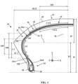
- a motorcycle tire unlike a tire for a motor vehicle, has a very curved tread, having a distinctive marked curvature.
- this curvature is characterized by the value of the curvature ratio H' / SG, where H' represents the radial height of the tread relative to the equatorial circumferential plane E passing through the radially outer ends of said tread, and SG represents the overall width of the tire, i.e. the axial width measured at the equator, as shown in the figure 1 .
- the tires targeted by the invention are such that the nominal aspect ratio H/S, expressed as a percentage, is at least equal to 40, preferably at least equal to 65 and is at most equal to 100, preferably at most equal to 80, and the nominal section width or flange thickness S is at least equal to 50 mm, preferably at least equal to 90 mm and more preferably at least equal to 100 mm and at most equal to 240 mm, preferably at most equal to 180 mm, more preferably at most equal to 150 mm.
- the nominal hook diameter D defining the diameter of the rim on which the tire is mounted, is at least equal to 10 inches, preferably at least equal to 13 inches and at most equal to 21 inches, preferably at most equal to 16 inches.
- axial direction is meant the direction substantially parallel to the main axis of the tire, i.e. the axis of rotation of the tire.
- Circumferential direction means the direction which is substantially perpendicular to both the axial direction and a radius of the tire (in other words, tangent to a circle whose center is on the axis of rotation of the tire).
- radial direction is meant the direction along a radius of the tire, that is to say any direction intersecting the axis of rotation of the tire and substantially perpendicular to this axis.
- median plane of the tire we mean the plane perpendicular to the axis of rotation of the tire which is located at mid-axial distance of the two beads and passes through the axial center of the crown reinforcement.
- equatorial circumferential plane of the tire we mean, in a meridian section plane, the plane passing through the equator of the tire, perpendicular to the median plane and to the radial direction.
- the equator of the tire is, in a meridian section plane (plane perpendicular to the circumferential direction and parallel to the radial and axial directions) the axis parallel to the axis of rotation of the tire and passing through the axially outermost points of the tire.
- the height H of the tire is the radial distance between the radially outermost point of the tread intended to be in contact with the ground and the radially innermost point of the tire intended to be in contact with a support, for example a rim.
- meridian plane is meant a plane parallel to and containing the axis of rotation of the tire and perpendicular to the circumferential direction.
- each bead is meant the portion of the tire intended to allow the tire to be attached to a mounting support, for example a wheel comprising a rim.
- a mounting support for example a wheel comprising a rim.
- each bead is in particular intended to be in contact with a hook on the rim allowing it to be attached.
- the principal direction in which a wire reinforcement element extends is understood to mean the direction in which the wire reinforcement element extends along its greatest length.
- the principal direction in which a wire reinforcement element extends may be rectilinear or curved, the reinforcement element being able to describe a rectilinear or wavy trajectory along its principal direction.
- portion of the assembly, layer or tire lying axially between the axial edges of a wound assembly or layer or reinforcement we mean a portion of the assembly, layer or tire extending axially and lying between the radial planes passing through the axial edges of the wound assembly or layer or reinforcement.
- portion of a wound assembly intended to extend axially portion of a wound assembly extending axially or portion of a layer extending axially radially perpendicular to a reference assembly or a reference layer, we mean a portion of said assembly or said layer comprised between the radial projections of the axial edges of the reference assembly or of the reference layer on said assembly or said layer.
- any interval of values denoted by the expression "between a and b" represents the domain of values from greater than a to less than b (i.e., excluding the limits a and b), while any interval of values denoted by the expression “from a to b” signifies the domain of values ranging from a to b (i.e. including the strict limits a and b).
- the angle considered is the angle, in absolute value, the smallest of the two angles defined between the reference line, here the circumferential direction of the tire, and the principal direction in which the wire reinforcement element considered extends.
- each wire reinforcement element in the tire and during the process, by orientation of an angle, we mean the direction, clockwise or anti-clockwise, in which it is necessary to turn from the reference line, here the circumferential direction of the support, assembly or tire, defining the angle to reach the main direction in which the wire reinforcement element considered extends.
- the angles considered formed by the main directions in which the crown and carcass wire reinforcement elements extend are by convention angles of opposite orientations and the angle formed by the main direction in which each crown wire reinforcement element extends is, in absolute value, the smaller of the two angles defined between the reference line, here the circumferential direction of the support, assembly or tire and the main direction in which the crown wire reinforcement element extends.
- the angle formed by the main direction in which each crown wire reinforcement element extends defines an orientation which is opposite to that formed by the angle of the main direction in which each carcass wire reinforcement element extends.
- each carcass wire reinforcement element has, between the portions, transition zones where the angle is substantially variable, the portion of the carcass layer extending axially in radial line with the crown layer and whose ACS angle is characterized has a curvilinear width in the axial direction equal to at least 30%, preferably at least 40% of the curvilinear width in the axial direction of the crown layer.
- the portion of the carcass layer extending axially in radial line with the crown layer and whose ACS angle is characterized has a curvilinear width in the axial direction equal to at most 90%, preferably at most 80% of the curvilinear width in the axial direction of the crown layer.
- the median plane of the tire intersects that portion of the carcass layer extending axially in line with the crown layer. More preferably, this portion of the carcass layer extending axially in radial line with the crown layer is centered axially on the median plane of the tire.
- curvilinear width in the axial direction is meant the width measured in a meridian section plane between the two axial edges of the corresponding layer following the curvature of said layer, for example following a curved line passing through the middle of the radial thickness of said layer. This width is said to be curvilinear as opposed to the straight width which would be measured between the two axial edges of the layer parallel to the axis of rotation of the tire between the two axial edges.
- the polymeric material strip consists of a layer of a polymeric material, preferably elastomeric, or consists of a stack of several layers, each layer being made of a polymeric material, preferably elastomeric.
- the crown comprises a single crown reinforcement.
- the crown is, with the exception of the crown reinforcement, devoid of any reinforcement reinforced by wire reinforcement elements.
- the wire reinforcement elements of such reinforcements excluded from the crown of the tire comprise the metal wire reinforcement elements and the textile wire reinforcement elements.
- the crown is constituted by the tread and the crown reinforcement.
- the carcass reinforcement is arranged directly radially in contact with the crown reinforcement and the crown reinforcement is arranged directly radially in contact with the tread.
- the sum of the absolute values of the AT angle and the ACS angle is strictly less than or equal to 70°, preferably less than or equal to 60°, and more preferably ranges from 40° to 60°.
- the radially outer layer is the layer that breaks first, on the one hand because the wire reinforcement elements of this radially outer layer are subjected to significantly greater tensions than those to which the wire reinforcement elements of the radially inner layer are subjected, and this because of its radially outer position and, on the other hand, because of the presence of a thickness of elastomeric material between the two layers which protects, through its shear when it is subjected to the breaking energy test, the radially inner layer.
- the radially outer layer is the fusible layer and the full strength potential of the assembly formed by the two radially inner and outer layers is not exploited.
- the inventors discovered that reducing the angular deviation between the principal directions of the crown and carcass wire reinforcement elements allows a significant improvement in the breaking energy to be obtained.
- the inventors hypothesize that by reducing the angular deviation, the tension difference between the crown and carcass wire reinforcement elements during the breaking energy test is significantly reduced compared to a bias-type tire, which allows the full strength potential of the assembly formed by the two crown and carcass layers to be exploited.
- the ratio of the breaking strength of the crown layer to the breaking strength of the carcass layer is strictly greater than 1, preferably ranging from 1.10 to 1.45 and more preferably from 1.25 to 1.35.
- angles AT and ACS The smaller the angles AT and ACS, the smaller the preferred ratio.
- the person skilled in the art will know, depending on the angles AT and ACS that he has chosen, how to determine the optimal ratio, if necessary by successive tests by varying the mechanical strengths of each of the crown and carcass layers.
- the breaking force of a wire reinforcement element of the layer is measured, for example according to the ASTM D 885/D 885M - 10a standard of 2014. Then, the breaking force of the wire reinforcement element is multiplied by the density of wire reinforcement elements per unit width of the ply intended to form the layer, here by the number of wire reinforcement elements per mm of ply intended to form the layer, this number being determined in a direction perpendicular to the direction in which the wire reinforcement elements extend in the ply intended to form the layer.
- the mechanical strengths, and in particular the densities of wire reinforcement elements of each of the crown and carcass layers are measured before the deformation step on each ply intended to form the corresponding layer.
- each crown and carcass wire reinforcement element comprises an assembly of several elementary textile monofilaments.
- the crown and carcass wire reinforcement elements are identical and, in order to differentiate the breaking strengths of the crown layer and the carcass layer, the ratio of the density of crown wire reinforcement elements to the density of carcass wire reinforcement elements is strictly greater than 1, preferably ranging from 1.10 to 1.45 and more preferably from 1.25 to 1.35.
- elementary monofilament is meant a monolithic filament made of a given material and resulting, for example, from the spinning of this material, for example by melt spinning, solution spinning or gel spinning.
- the elementary monofilaments typically have diameters ranging from 2 ⁇ m to 0.50 mm.
- the elementary monofilaments are assembled in the form of strands comprising at least 2 elementary monofilaments, typically more than 10 elementary monofilaments, preferably more than 100 elementary monofilaments and more preferably more than 200 elementary monofilaments.
- textile elementary monofilament is meant a non-metallic elementary monofilament.
- each wire reinforcement element of the crown layer in the case where condition I is satisfied or of the carcass layer in the case where condition II is satisfied comprises an assembly of several elementary textile monofilaments chosen from elementary aliphatic polyamide monofilaments, elementary polyester monofilaments or elementary monofilaments of cellulose derivatives and the assemblies of these elementary monofilaments, preferably chosen from elementary aliphatic polyamide monofilaments, elementary polyester monofilaments and the assemblies of these elementary monofilaments.
- each wire reinforcement element of the crown layer in the case where condition I is satisfied or of the carcass layer in the case where condition II is satisfied comprises an assembly of several elementary textile monofilaments chosen from elementary aromatic polyamide monofilaments and the assemblies of these elementary aromatic polyamide monofilaments with elementary textile monofilaments different from the elementary textile polyamide monofilaments aromatic.
- each wire reinforcement element will be easily determined by a person skilled in the art on the one hand, according to the compromise between rolling resistance and the cost of the tire and, on the other hand, according to the other architectural elements of the tire.
- a limited deflection makes it possible to ensure good flattening of the tire in the contact patch unlike a tire according to the first variant in which, due to wire reinforcement elements having a lower modulus, the tire is likely to blister under load and therefore to have an irregular contact patch leading to poorer flattening. Thanks to the improvement in flattening in the second variant, the rolling resistance of the tire is significantly improved.
- the elementary textile monofilaments other than the elementary textile monofilaments of aromatic polyamide are preferably chosen from among the elementary monofilaments of aliphatic polyamide and the elementary monofilaments of polyester.
- the wire reinforcement elements of each layer are embedded in an elastomeric matrix.
- the different layers may comprise the same elastomeric matrix or distinct elastomeric matrices.
- elastomeric matrix a matrix exhibiting, in the crosslinked state, an elastomeric behavior.
- a matrix is advantageously obtained by crosslinking a composition comprising at least one elastomer and at least one other component.
- the composition comprising at least one elastomer and at least one other component comprises an elastomer, a crosslinking system and a filler.
- the compositions used for these layers are conventional compositions for calendering reinforcements, typically based on natural rubber or other diene elastomer, a reinforcing filler such as carbon black, a vulcanization system and the usual additives.
- the adhesion between the wire reinforcement elements and the matrix in which they are embedded is ensured for example by a usual adhesive composition, for example an RFL type glue or equivalent glue.
- the axial edge of the carcass layer is located radially inside the equator of the tire and, preferably, located radially inside the equator of the tire at a radial distance from the equator greater than or equal to 50% of the radial distance between the equator and the radially innermost point of the tire.
- the main direction of each carcass wire reinforcement element forms, with the circumferential direction of the tire, in at least a portion of the axially inner portion of the carcass layer extending radially in each sidewall, an angle ACF, ranging, in absolute value, from 80° to 90°.
- the angle ACF makes it possible to give the tire according to the invention the same advantages as those given by the carcass layer of the radial type tire.
- the invention uses the variation of the angle formed by the main direction of the carcass wire reinforcement elements depending on whether it is radially perpendicular to the crown layer or in each sidewall to obtain an inexpensive tire capable of maintaining its expected radial dimension without giving up the advantages of a radial type tire.
- each portion of the axially inner portion of the carcass layer extending radially in each sidewall and whose ACF angle is characterized has a curvilinear height in the radial direction equal to at least 5%, preferably at least 15% and more preferably at least 30% of the curvilinear height in the radial direction of the portion of the axially inner portion of the carcass layer not having any portion of crown layer or carcass axially facing.
- each portion of the axially inner portion of the carcass layer extending radially in each sidewall and whose ACF angle is characterized as having a curvilinear height in the radial direction equal to at most 80%, preferably at most 70% of the curvilinear height in the radial direction of the portion of the axially internal portion of the carcass layer not having any portion of crown layer or carcass axially opposite.
- the portion of each axially inner and axially outer portion of the carcass layer extending radially in each sidewall and of which the ACF angle is characterized has a curvilinear height in the radial direction equal to at least 50%, preferably at least 60% and more preferably at least 70% of the curvilinear height in the radial direction of the portion of the axially outer portion of the carcass layer in contact with the axially inner portion of the carcass layer.
- each portion of the axially inner portion of the carcass layer extending radially in each sidewall and of which the ACF angle is characterized has a curvilinear height in the radial direction equal to at most 100%, preferably at most 90% and more preferably at most 80% of the curvilinear height in the radial direction of the portion of the axially outer portion of the carcass layer in contact with the axially inner portion of the carcass layer.
- curvilinear height in the radial direction is meant the height measured in a meridian section plane following the curvature of said layer, for example following a curved line passing through the middle of the radial thickness of said layer. This height is said to be curvilinear as opposed to the straight height which would be measured between the two ends of the portion parallel to the radial direction of the tire.
- the method according to the invention it is possible to obtain different final angles B2 and B3 having absolute values allowing, as explained above, to maintain the expected radial dimension of the tire. Furthermore, thanks to the common deformation step of the carcass and crown assemblies, the manufacturing time is reduced compared to a method for manufacturing a radial tire.
- the initial angles A2 and A3 vary during the deformation step to reach their final angles B2 and B3S, with the exception of the portion of the wound carcass assembly wound around the circumferential reinforcing elements in which the main direction of the wire carcass reinforcing elements remains substantially identical with respect to the circumferential direction of the support and therefore of the tire.
- the variation of the angle formed with the circumferential direction of the support by the main direction of the wire reinforcement elements of the carcass causes a variation of the angle formed by the main direction of the wire reinforcement elements of the crown with the circumferential direction of the support, this variation being different depending on whether one is in the portion of the wound carcass assembly extending axially in radial line with the wound crown assembly or whether one is in the portion of the carcass assembly intended to extend radially in each sidewall.
- the variation of the initial angles A2 and A3 can be determined by a person skilled in the art as a function of the deformation rate used during the method.
- the deformation rate is determined in a manner known to a person skilled in the art as a function of the axial approximation of the axial edges of the wound carcass assembly and the radial enlargement of the assembly between its cylindrical shape and its toric shape.
- the determination of the initial angles as a function of the final angles depends, in a manner known to a person skilled in the art, on the deformation rate as explained in FR2797213 and in FR1413102 .
- the carcass assembly is intended to form the single carcass layer by wrapping the carcass assembly at most one complete turn.
- the crown assembly is intended to form the single crown layer by wrapping the crown assembly at most one complete turn around the carcass assembly.
- the wound carcass assembly is comprised of a carcass ply which is intended to form the carcass layer.
- the carcass ply is axially continuous.
- the wound carcass assembly is formed with several carcass plies
- several carcass plies will preferably be used in which the main directions of the carcass wire reinforcement elements are all parallel to each other.
- the rolled crown assembly is comprised of a crown ply which is intended to form the single crown layer.
- the crown ply is axially continuous.
- crown plies will preferably be used in which the main directions of the crown wire reinforcement elements are all parallel to each other. to each other.
- main directions of the wire reinforcement elements at the top not being parallel to each other from one top layer to the other.
- a rolled rolling assembly intended to form the tread is formed by winding a rolling ply or several rolling plies, radially outside the rolled crown assembly.
- the wound rolling assembly is comprised of a tread ply which is intended to form the tread.
- the tread ply is axially continuous.
- the step of deforming the substantially cylindrical assembly so as to obtain the substantially toroidal assembly is carried out in a crosslinking mold of the assembly.
- a green blank of the tire is formed to be crosslinked in the crosslinking mold.
- the green blank is formed from the assembly described above, including in particular the wound bearing assembly.
- the green blank is positioned in the crosslinking mold and a radially inner wall of the green blank is pressurized, for example by means of a deformable membrane, so as to press a radially outer wall of the green blank against an inner wall of the crosslinking mold.
- the deformation generated by the molding step is thus taken advantage of to deform the assembly from its substantially cylindrical shape to its substantially toric shape.
- the use of a deformable manufacturing support between a substantially cylindrical shape and a toric shape and the performance of a superfluous deformation step using this deformable support are avoided.
- the final angles formed by the main direction of each wire reinforcement element with the circumferential direction of the assembly are substantially equal to the angles formed by the main direction of each wire reinforcement element with the circumferential direction of the tire once the latter has been manufactured.
- the step of deforming the shape assembly substantially cylindrical so as to obtain the assembly of substantially toric shape is produced on the support, the final angles formed by the main direction of each wire reinforcement element with the circumferential direction of the assembly being, in absolute value, strictly greater than the angles formed by the main direction of each wire reinforcement element with the circumferential direction of the tire once the latter has been manufactured.
- B2>AT, B3S>ACS and B3F>ACF B2>AT, B3S>ACS and B3F>ACF.
- a green blank of the tire is formed to be crosslinked in the crosslinking mold.
- the green blank is formed from the assembly described above and notably comprises the wound bearing assembly.
- the method subsequently comprises a step of molding the green blank carried out so as to obtain the final angles AT, ACS, ACF, for example, by means of a deformable membrane.
- the method comprises a step of molding a raw blank formed from the assembly of substantially toric shape carried out so as to obtain, after the molding step, the angles AT, ACS and ACF.
- the deformation step is carried out such that the final density of crown wire reinforcement elements is strictly greater than the initial density of crown wire reinforcement elements.
- a densification of the wound crown assembly occurs such that it is possible to form a crown layer having a relatively high mechanical strength from one or more crown plies having a relatively low density of crown wire reinforcement elements. The greater the densification, the greater the gain.
- the wound carcass assembly having an initial density of carcass wire reinforcement elements at the start of the deformation step and a final density of carcass wire reinforcement elements at the end of the deformation step
- the deformation step is carried out such that the final density of carcass wire reinforcement elements is strictly greater than the initial density of carcass wire reinforcement elements.
- the inventors have discovered that, by choosing angles A2 and A3 separated by a sufficient angular difference, and more precisely strictly greater than 90°, during the deformation step, there was a first phase of de-densification of the entire rolled crown until an angular difference equal to 90° was reached, then a second phase of densification of the entire rolled crown until the final angle was reached. The greater the angular difference, the greater the first phase of de-densification.
- the person skilled in the art will choose the angular difference allowing sufficient de-densification to, on the one hand, avoid contact between the crown or carcass wire reinforcement elements and, on the other hand, obtain a crown layer having sufficient mechanical strength during the second densification phase.
- the sum of the absolute values of the initial angle A2 and the initial angle A3 is strictly greater than 90°, preferably ranging from 95° to 120° and more preferably from 100° to 115°.
- this density will be considered measured on the crown assembly and on the carcass assembly arranged radially perpendicular to the crown assembly.
- This density is, in a manner similar to the density measured on each undeformed ply, the density of wire reinforcement elements per unit of curvilinear width of the assembly considered, that is to say, taking into account the curvature of the blank during the deformation step, here by the number of wire reinforcement elements per mm of assembly, this number being determined in a direction perpendicular to the direction in which the wire reinforcement elements extend in the assembly.
- the assembly of substantially cylindrical shape is deformed so as to obtain the assembly of substantially toric shape such that, after the deformation step, the main direction of each wire reinforcement element of the carcass forms, with the circumferential direction of the assembly, a final angle B3F ranging, in absolute value, from 80° to 90°, in a portion of the wound carcass assembly intended to form at least a portion of the axially inner portion of the carcass layer intended to extend radially in each sidewall.
- the rolled crown assembly or the rolled carcass assembly is formed by minimizing the length of the junctions when rolling the angled cut plies by means of a sufficiently large angle, i.e. greater than or equal to 25°, and on the other hand, the rolled carcass assembly or the rolled crown assembly is formed from one or more plies not requiring angled cutting and butting by means of an angle as close as possible to 90°, i.e. ranging from 80° to 90°.
- This variant makes it possible to reduce the cost of the process as much as possible by limiting the cycle time required to form the rolled assemblies.
- this variant is very preferentially implemented in the case where the condition El is satisfied.
- the rolled crown assembly or the rolled carcass assembly is formed by minimizing the length of the junctions when rolling the angled cut plies by means of a sufficiently large angle, i.e. greater than or equal to 25°, and on the other hand, the rolled carcass assembly or the rolled crown assembly is formed so as to obtain a relatively moderate final angle in each sidewall. in order to increase the drift rigidity as much as possible as shown in the comparative tests described below.
- this other variant is very preferentially implemented in the case where the condition El is satisfied.
- a reference X, Y, Z is shown corresponding to the usual axial (X), radial (Y) and circumferential (Z) directions of a tire.
- a reference x, y, z corresponding to the usual directions respectively axial (x), radial (y) and circumferential (z) of a manufacturing support having a substantially cylindrical shape around a main axis A.
- These directions respectively axial (x), radial (y) and circumferential (z) are also used to refer to the directions respectively axial (x), radial (y) and circumferential (z) of a raw blank and of the assembly having substantially cylindrical and toric shapes around a main axis A'.
- the tire 10 is substantially of revolution around an axis substantially parallel to the axial direction X.
- the tire 10 is here intended for a motorcycle and has dimensions 90/90 - 14.
- the tire is notably characterized by a curvature rate ranging from 0.15 to 0.50, preferably ranging from 0.20 to 0.40 and here equal to 0.37.
- the tire 10 comprises a crown 12 comprising a tread 20 intended to come into contact with a ground during rolling and a crown reinforcement 14 extending in the crown 12 in the circumferential direction Z.
- the tire 10 also comprises a sealing layer 15 to an inflation gas being intended to delimit an internal cavity closed with a mounting support of the tire 10 once the tire 10 is mounted on the mounting support, for example a rim.
- the sealing layer 15 comprises an elastomeric composition comprising an elastomeric matrix comprising at least 50 phr of one or more butyl elastomers.
- the crown reinforcement 14 comprises a crown reinforcement 16 comprising a single crown layer 18 and is, in this case, made up of the single crown layer 18. For the sake of simplification, we will speak of the crown layer 18 without recalling each time that this layer is unique.
- the crown reinforcement 14 is radially surmounted by the tread 20.
- the tire 10 comprises two sidewalls 22 extending the crown 12 radially inwards.
- the tire 10 further comprises two beads 24 radially inwards to the sidewalls 22.
- Each sidewall 22 connects each bead 24 to the crown 12.
- Each bead 24 comprises at least one circumferential reinforcing element 26, in this case a rod 28 radially surmounted by a mass of filling rubber 30.
- the tire 10 comprises a carcass reinforcement 32 anchored in each bead 24.
- the carcass reinforcement 32 extends in each sidewall 22 and radially internally to the crown 12.
- the crown reinforcement 14 is arranged radially between the tread 20 and the carcass reinforcement 32.
- the carcass reinforcement 32 comprises a single carcass layer 34 and in the species, is made up of the single layer of carcass 34. For the sake of simplification, we will speak of the layer of carcass 34 without recalling each time that this layer is unique.
- Each crown layer 18 and carcass layer 34 comprises an elastomeric matrix in which one or more wire reinforcement elements of the corresponding layer are embedded.
- the crown layer 18 is delimited axially by two axial edges 18A, 18B of the crown layer 18.
- the crown layer 18 comprises crown wire reinforcement elements 180 extending axially from the axial edge 18A to the other axial edge 18B of the crown layer 18 substantially parallel to each other.
- Each crown wire reinforcement element 180 extends in a main direction D2 of each crown wire reinforcement element 180.
- the direction D2 forms, with the circumferential direction Z of the tire 10, an angle AT, in absolute value, ranging from 10° to 25°.
- AT 15°.
- the carcass layer 34 is delimited axially by two axial edges 34A, 34B of the carcass layer 34.
- the carcass layer 34 comprises carcass wire reinforcement elements 340 extending axially from the axial edge 34A to the other axial edge 34B of the carcass layer 34.
- Each carcass wire reinforcement element 340 extends in a main direction D3 of each carcass wire reinforcement element 340 forming, with the circumferential direction Z of the tire 10 an angle ACS, in absolute value, ranging from 20° to 65° and preferably ranging from 20° to 60° in a portion 34S of the carcass layer 34 extending axially radially above the crown layer 18.
- ACS 40°.
- the portion 34S of the carcass layer 34 extending axially perpendicular to the crown layer 18 has a curvilinear width LS in the axial direction equal to at least 30%, preferably at least 40% of the curvilinear width in the axial direction LA of the crown layer 18 and equal to at most 90%, preferably at most 80% of the curvilinear width in the axial direction LA of the crown layer 18.
- LS/LA 0.75.
- the median plane M of the tire 10 intersects this portion 34S. More preferably, this portion 34S is centered axially on the median plane M of the tire 10.
- the sum of the absolute values of the angles AT and ACS is strictly less than or equal to 70°, preferably less than or equal to 60°, and more preferably ranging from 40° to 60°.
- 55°.
- the carcass layer 34 comprises an axially inner portion 34I extending from the median plane M passing through one of the flanks 22 into the bead 24 radially inside the circumferential reinforcing element 26.
- the layer carcass layer 34 also comprises an axially outer portion 34E arranged axially outside the inner axial portion 34I and extending from the bead 24 radially inwardly to the circumferential reinforcing element 26 to the edge 34A of the carcass layer 34.
- the axially inner 34I and axially outer 34E portions are arranged such that the carcass layer 34 is wrapped around each circumferential reinforcing element 26 of each bead 24.
- the mass of filling rubber 30 is interposed axially between the axially inner 34I and axially outer 34E portions.
- the axial edge 34A of the carcass layer 34 is located radially inside the equator E of the tire 10 and, preferably, located radially inside the equator E of the tire 10 at a radial distance C1 from the equator E greater than or equal to 50% of the radial distance E1 between the equator and the most radially inner point of the tire.
- each carcass wire reinforcement element 340 forms, with the circumferential direction Z of the tire 10, an angle ACF, in absolute value, ranging from 80° to 90° in at least one portion 34F of the axially inner portion 34I of the carcass layer 34 extending radially in each sidewall 22.
- ACF 90°.
- Each portion 34F of the axially inner portion 34I of the carcass layer 34 extending radially in each sidewall 22 has a curvilinear height LF in the radial direction equal to at least 5%, preferably at least 15% and more preferably at least 30% of the curvilinear height LR in the radial direction of the portion 34L of the axially inner portion 34I of the carcass layer 34 not having any portion of crown layer 18 or carcass 34 axially facing.
- Each portion 34F of the axially inner portion 34I of the carcass layer 34 extending radially in each sidewall 22 has a curvilinear height LF in the radial direction equal to at most 90%, preferably at most 80% of the curvilinear height LR in the radial direction of the portion 34L of the axially inner portion 34I of the carcass layer 34 not having any portion of crown layer 18 or carcass 34 axially facing.
- LF/LR 0.75.
- each carcass wire reinforcement element 340 forms, with the circumferential direction Z of the tire 10, an angle ACT, in absolute value, ranging from 80° to 90°, in the axially outer portion 34E as well as in a portion 34IT of the axially inner portion 34I axially facing the axially outer portion 34E.
- each crown 180 and carcass 340 wire reinforcement element comprises an assembly of several elementary textile monofilaments chosen from elementary aliphatic polyamide monofilaments, elementary polyester monofilaments or elementary monofilaments of cellulose derivatives and the assemblies of these elementary monofilaments, preferably chosen from elementary aliphatic polyamide monofilaments, elementary polyester monofilaments and the assemblies of these elementary monofilaments.
- each crown 180 and carcass 340 wire reinforcement element is an assembly of two strands of HMLS grade polyethylene terephthalate, each having a count equal to 144 tex and twisted individually at 420 turns/meter in one direction then collectively at 420 turns/meter in the other direction.
- the ratio of the density d2 of crown wire reinforcement elements to the density d3 of carcass wire reinforcement elements is strictly greater than 1, preferably ranging from 1.10 to 1.45 and more preferably from 1.25 to 1.35.
- d2/d3 1.29.
- the crown layer 18 has a density d2 of crown wire elements 180 equal to 139 wires per decimeter of crown layer 18.
- the carcass layer 34 has a density d3 of carcass wire elements 340 equal to 108 wires per decimeter of carcass layer 34.
- the crown layer 18 has a breaking strength Rs greater than or equal to 1900 daN/dm, preferably greater than or equal to 2300 daN/dm and less than or equal to 2600 daN/dm.
- the mechanical strengths Rs and Rc also satisfy the condition according to which the ratio of the breaking strength Rs of the crown layer 18 to the breaking strength Rc of the carcass layer 34 is strictly greater than 1, preferably ranging from 1.10 to 1.45 and more preferably from 1.25 to 1.35.
- the tire 10 is obtained by a method according to a first embodiment of the invention which will be described with reference to the Figures 4 to 12 .
- a rolled crown assembly 50 and a rolled carcass assembly 52 are manufactured by arranging the wire reinforcement elements 180 and 340 of each assembly 50 and 52 parallel to each other and embedding them, for example by calendering, in a non-crosslinked composition comprising at least one elastomer, the composition being intended to form an elastomeric matrix once crosslinked.
- a so-called straight ply is obtained, in which the wire reinforcement elements are parallel to each other and are parallel to the main direction of the ply.
- each straight ply is cut at a cutting angle and these portions are joined to each other so as to obtain a so-called angled ply, in which the wire reinforcement elements of the ply are parallel to each other and form an angle with the main direction of the ply equal to the cutting angle.
- an angled ply is formed only for the crown ply, the carcass ply advantageously not requiring cutting in this first embodiment.
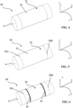
- a wound sealing assembly 72 intended to form the sealing layer 15 is formed by winding a sealing sheet 70 around a support 60 having a substantially cylindrical shape around its main axis A.
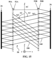
- the wound carcass assembly 52 intended to form the carcass layer 34 is formed by winding the carcass ply 51 around the support 60.
- the wound carcass assembly 52 is delimited axially by two axial edges 52A, 52B of the wound carcass assembly 52 and comprises the wire carcass reinforcement elements 340 extending substantially parallel to each other axially from the axial edge 52A to the other axial edge 52B of the wound carcass assembly 52.
- Each wire carcass reinforcement element 340 extends, in the carcass ply 51, in a main direction K3 of each wire carcass reinforcement element 340 in the carcass ply 51.
- the main direction K3 forms, with the direction circumferential z of the support 60, an initial angle A3 of each wire reinforcement element of carcass 340, in absolute value, ranging from 80° to 90°.
- A3 90°.
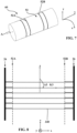
- the two circumferential reinforcing elements 26 are arranged around the wound carcass assembly 52 and each axial edge 52A, 52B of the wound carcass assembly 52 is turned axially inwards so as to radially cover each circumferential reinforcing element 26 with each axial edge 52A, 52B of the wrapped carcass assembly 52 and that the wrapped carcass assembly 52 is wrapped around each circumferential reinforcing element 26.
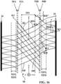
- FIG 8 It was represented on the figure 8 a diagram illustrating the arrangement of the wire reinforcement elements 340 of the carcass at the end of the step of axially turning over the axial edges 52A, 52B of the carcass assembly wound 52 around the circumferential reinforcement elements 26.
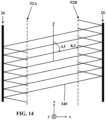
- the crown ply 49 is formed by winding, radially outside the wound carcass assembly 52, the wound crown assembly 50 intended to form the crown layer 18.
- the wound crown assembly 50 is delimited axially by two axial edges 50A, 50B of the wound crown assembly 50 and comprises the crown wire reinforcement elements 180 extending substantially parallel to each other axially from the axial edge 50A to the other axial edge 50B of the wound crown assembly 50.
- Each crown wire reinforcement element 180 extends, in the crown ply 49, in a main direction K2 of each crown wire reinforcement element 180 in the crown ply 49.
- the main direction K2 forms, with the circumferential direction z of the support 60, an initial angle A2 of each wire reinforcement element with apex 180, in absolute value, greater than or equal to 20°, and preferably ranges from 25° to 50°.
- A2 25°.
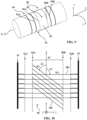
- the wound sealing assembly 72, the wound carcass assembly 52 and the wound crown assembly 50 then form an assembly 58 of substantially cylindrical shape around a main axis A' of the assembly substantially coincident with the main axis A of the support 60.
- the initial angles A2 and A3 are different in absolute values and of opposite orientations.
- the sum of the absolute values of the initial angle A2 and the initial angle A3 is strictly greater than 90°, preferably ranging from 95° to 120° and more preferably from 100° to 115°.
- 115°.
- a wound rolling assembly intended to form the tread 20 is formed.
- a raw blank 11 of the tire intended to be crosslinked in the crosslinking mold is then obtained.
- the raw blank 11 comprising the assembly 58 and formed from this assembly 58 is transferred from the support 60 to a crosslinking mold comprising an internal cavity (not shown).
- a crosslinking mold comprising an internal cavity (not shown).
- the raw blank 11 and therefore also the assembly 58 of substantially cylindrical shape are deformed so as to obtain the raw blank 11 of substantially toric shape and therefore the assembly 58 also of substantially toric shape around the main axis A' of the assembly 58.
- the step of deforming the blank 11 and therefore the assembly 58 is therefore carried out during a molding step in the crosslinking mold, for example by pressurizing a membrane inside the raw blank 11.
- the deformed blank 11 illustrated in the Figures 11 and 12 are examples of the raw blank 11 illustrated in the Figures 11 and 12 .
- the assembly 58 of substantially cylindrical shape is deformed around the main axis A' of the assembly 58 so as to obtain the assembly 58 of substantially toric shape around this main axis A' also so that, after the deformation step, the main direction K3 of each wire carcass reinforcement element 340 forms, with the circumferential direction z of the assembly 58, a final angle B3F of each wire carcass reinforcement element 340 ranging, in absolute value, from 80° to 90°, in a portion 52F of the wound carcass assembly 52 intended to form the portion 34F of the axially inner portion 34I of the carcass layer 34.
- the final angle B3T formed by the main direction K3 of each carcass wire reinforcement element 340, with the circumferential direction z of the assembly 58, in a portion of the wound carcass assembly 52 intended to form the axially outer portion 34E as well as in a portion of the wound carcass assembly 52 intended to form the portion 34IT of the axially inner portion 34I axially facing the axially outer portion 34E is substantially identical to the initial angle A3 before the deformation step.
- B3T 90°.
- the assembly 58 is deformed into a substantially cylindrical shape around the axis principal axis A' of the assembly 58 so as to obtain the assembly 58 of substantially toric shape around this principal axis A' also so that, after the deformation step, the principal direction K2 of each wire reinforcement element of vertex 180 forms, with the circumferential direction z of the assembly 58, a final angle B2 of each wire reinforcement element of vertex 180, in absolute value, ranging from 10° to 25°.
- B2 15°.
- angles B2 and B3S are different in absolute value and of opposite orientations.
- Another aspect of the process is the variation of the density of wire reinforcement elements.
- the wound crown assembly 50 has an initial density d2i of crown wire reinforcement elements 180 at the start of the deformation step and a final density d2f of crown wire reinforcement elements 180 at the end of the deformation step.
- the wound carcass assembly 52 has an initial density d3i of carcass wire reinforcement elements 340 at the start of the deformation step and a final density d3f of carcass wire reinforcement elements 340 at the end of the deformation step.
- Each final density d2f, d3f is substantially equal respectively to the density d2, d3 of the tire 10 described above.
- the ratio between each final density d2f, d3f and each initial density d2i, d3i is less than or equal to 1.30, preferably less than or equal to 1.25 and here equal to 1.20.
- the deformation step is performed such that each final density d2f, d3f is strictly greater than each initial density d2i, d3i and also such that the density of wire reinforcement elements of vertex 180 decreases from the initial density d2i to reach a minimum density d2min of wire reinforcement elements of vertex 180 strictly less than the initial density d2i.
- d2min 104 wires per decimeter. Then, the density of wire reinforcement elements of vertex 180 increases from the minimum density d2min to reach the final density d2f.
- the angle AT is equal to -21° and the angle ACS is equal to +37°.
- Each portion 34FI and 34FE of each axially inner portion 34I and axially outer portion 34E of the carcass layer 34 has a curvilinear height LF in the radial direction equal to at least 50%, preferably at least 60% and more preferably at least 70% and at most 100%, preferably at most 90% and more preferably at most 80% of the curvilinear height LC in the radial direction of the portion 34C of the axially outer portion 34E of the carcass layer 34 in contact with the axially inner portion 34I of the carcass layer 34.
- LF/LC 100% even if this is not correctly represented on the figure 13 whose main purpose is to illustrate the determination of the heights LF and LC which, on the figure 13 should be equal.
- each wire reinforcement element of the crown layer 180 comprises an assembly of several elementary textile monofilaments chosen from elementary aromatic polyamide monofilaments and assemblies of these elementary aromatic polyamide monofilaments with elementary textile monofilaments different from the elementary aromatic polyamide textile monofilaments.
- each crown 180 wire reinforcement element is an assembly of two strands of aromatic polyamide, for example aramid, each having a count equal to 167 tex and twisted individually at 290 turns/meter in one direction then collectively at 290 turns/meter in the other direction.
- Both the top 49 and carcass 51 plies are angled plies.
- the wound carcass assembly 52 is formed by winding the carcass ply 51 around the support 60.
- the main direction K3 forms, with the circumferential direction z of the support 60, an initial angle A3 of each carcass wire reinforcement element 340, in absolute value, greater than or equal to 50° and preferably ranging from 50° to 80°.
- A3 +75°.
- the crown ply 49 is formed by winding, radially outside the wound carcass assembly 52, the wound crown assembly 50.
- the main direction K2 forms, with the circumferential direction z of the support 60, an initial angle A2 of each crown wire reinforcement element 180, in absolute value, greater than or equal to 20°, and preferably ranging from 25° to 50°.
- A2 -35°.
- the final angle B3T formed by the main direction K3 of each carcass wire reinforcement element 340, with the circumferential direction z of the assembly 58, in portions of the wound carcass assembly 52 intended to form portions radially inside each portion 34FI and 34FE of the carcass layer is substantially identical to the initial angle A3 before the deformation step.
- B3T 75°.
- the assembly 58 of substantially cylindrical shape is deformed around the main axis A' of the assembly 58 so as to obtain the assembly 58 of substantially toric shape around this main axis A' also so that, after the deformation step, the main direction K2 of each wire reinforcement element of vertex 180 forms, with the circumferential direction z of the assembly 58, a final angle B2 equal to -21°.
- the drift stiffness performance of different tires E, G and H conforming to the invention and F and I not conforming to the invention was also tested.
- the drift stiffness test is carried out by rolling the tested tire on a rolling machine and applying a given load (here successively 100 daN, 150 daN and 200 daN) under a pressure of 2.5 bars. During rolling, the tested tire is subjected to the given load and the tire is rotated by +0.5° around the radial axis perpendicular to the contact surface between the tire and the ground, then by +1° around this axis. Then, the measurement is repeated for angles of -0.5° and -1° around this axis. The force generated by the tire by the rolling support is then determined.
- the drift stiffness is then deduced, which is, for a given load, expressed in daN/°.
- the tires E, F are such that the axial edge 34A of the carcass layer 34 is interposed radially between the axially inner portion 34I of the carcass layer 34 and the crown layer 18 (as in the second embodiment).
- the tire G is such that the axial edge 34A of the carcass layer 34 is at the equator E.
- the tires H and I are such that the axial edge 34A of the carcass layer 34 is located radially inside the equator E (as in the first embodiment).
- tire E and to a much lesser extent, tire F in which the axially outer portion 34E rises radially above the equator E, have a largely improved drift rigidity compared with tires G, H and I in which the axially outer portion rises at most to the level of the equator.
- This improvement is maximum in the case of tire E according to the invention in which, by blocking the angle B3 during the shaping step thanks to the axially outer portion 34E rising radially above the equator E and by preventing it from reaching too high a value (the angle ACF of tire E is significantly lower than the 80°-90° interval in which the angle ACF of tire F is located), a significantly improved drift rigidity is obtained.
Landscapes
- Engineering & Computer Science (AREA)
- Mechanical Engineering (AREA)
- Tires In General (AREA)
- Ropes Or Cables (AREA)
Claims (15)
- Reifen (10) für Motorräder mit einem Scheitel (12), zwei Seitenwänden (22), zwei Wülsten (24), wobei jede Seitenwand (22) jeden Wulst (24) mit dem Scheitel (12) verbindet, wobei der Reifen (10) eine Karkassenbewehrung (32) aufweist, die in jedem Wulst (24) verankert ist und sich in jeder Seitenwand (22) und radial nach innen zum Scheitel (12) erstreckt, wobei die Karkassenbewehrung (32) eine einzelne Karkassenschicht (34) aufweist, wobei der Scheitel (12) Folgendes aufweist:- eine Lauffläche (20), die dazu bestimmt ist, beim Rollen des Reifens (10) mit einem Boden in Kontakt zu kommen,- eine Scheitelbewehrung (14), die radial zwischen der Lauffläche (20) und der Karkassenbewehrung (32) angeordnet ist, wobei die Scheitelbewehrung (14) eine einzelne Scheitelschicht (18) aufweist,wobei die Scheitelschicht (18) axial durch zwei axiale Ränder (18A, 18B) der Scheitelschicht (18) begrenzt ist und drahtförmige Scheitelverstärkungselemente (180) aufweist, die sich axial von einem axialen Rand (18A, 18B) zum anderen axialen Rand (18A, 18B) der Scheitelschicht (18) erstrecken, die einen im Wesentlichen parallel zu den anderen entlang einer Hauptrichtung (D2) jedes drahtförmigen Scheitelverstärkungselements (180), die mit der Umfangsrichtung (Z) des Reifens (10) einen Winkel AT bildet,wobei die Karkassenschicht (34) axial durch zwei axiale Ränder (34A, 34B) der Karkassenschicht (34) begrenzt ist und drahtförmige Karkassenverstärkungselemente (340) aufweist, die sich axial von einem axialen Rand (34A, 34B) zum anderen axialen Rand (34A, 34B) der Karkassenschicht (34) erstrecken, wobei sich jedes drahtförmige Karkassenverstärkungselement (340) entlang einer Hauptrichtung (D3) jedes drahtförmigen Karkassenverstärkungselements (340) erstreckt, die mit der Umfangsrichtung (Z) des Reifens (10) einen Winkel ACS in einem Abschnitt (34S) der Karkassenschicht (34) bildet, der sich axial im radialen Lot zur Scheitelschicht (18) erstreckt,wobei der Winkel AT und der Winkel ACS entgegengesetzte Orientierungen haben,dadurch gekennzeichnet, dass der Winkel AT und der Winkel ACS sich im Absolutwert unterscheiden, und dadurch, dass entweder die Bedingung I oder die Bedingung II erfüllt ist:I - der Absolutwert des Winkels AT reicht von 10° bis 25° und der Absolutwert des Winkels ACS reicht von 20° bis 65° in dem Abschnitt (34S) der Karkassenschicht (34), der sich axial im radialen Lot zur Scheitelschicht (18) erstreckt,II - der Absolutwert des Winkels AT reicht von 20° bis 65° und der Absolutwert des Winkels ACS reicht von 10° bis 25° in dem Abschnitt (34S) der Karkassenschicht (34), der sich axial im radialen Lot zur Scheitelschicht (18) erstreckt.
- Reifen (10) nach dem vorhergehenden Anspruch, wobei:- in dem Fall, dass Bedingung I erfüllt ist, der Absolutwert des Winkels ACS in dem Abschnitt (34S) der Karkassenschicht (34), der sich axial im radialen Lot zur Scheitelschicht (18) erstreckt, von 20° bis 60° reicht,- in dem Fall, dass Bedingung II erfüllt ist, der Absolutwert des Winkels AT von 20° bis 60° reicht.
- Reifen (10) nach einem der vorhergehenden Ansprüche, wobei die Summe der absoluten Werte des Winkels AT und des Winkels ACS strikt kleiner oder gleich 70° ist, vorzugsweise kleiner oder gleich 60° und besonders bevorzugt im Bereich von 40° bis 60° liegt.
- Reifen (10) nach einem der vorhergehenden Ansprüche, wobei das Verhältnis der Reißfestigkeit der Scheitelschicht zur Reißfestigkeit der Karkassenschicht strikt größer als 1 ist, vorzugsweise 1,10 bis 1,45 und besonders bevorzugt 1,25 bis 1,35.
- Reifen (10) nach einem der vorhergehenden Ansprüche, wobei jeder Wulst (24) ein Umfangsverstärkungselement (26) aufweist und wobei die Karkassenschicht (34) Folgendes aufweist:- einen axial inneren Abschnitt (341), der sich von der Mittelebene (M) des Reifens (10) durch eine der Seitenwände (22) bis in den Wulst (24) radial innen von dem Umfangsverstärkungselement (26) erstreckt, und- einen axial äußeren Abschnitt (34E), der axial außerhalb des axial inneren Abschnitts (341) angeordnet ist und sich von der Wulst (24) radialinnen von dem Umfangsverstärkungselement (26) bis zu einem der axialen Ränder (34A, 34B) der Karkassenschicht (34) erstreckt, wobei die axial inneren (341) und axial äußeren (34E) Abschnitte so angeordnet sind, dass die Karkassenschicht (34) um das Umfangsverstärkungselement (26) gewickelt wird.
- Reifen (10) nach Anspruch 5, wobei der axiale Rand (34A, 34B) der Karkassenschicht (34) radial innerhalb des Äquators (E) des Reifens (10) angeordnet ist und vorzugsweise radial innerhalb des Äquators (E) des Reifens (10) in einem radialen Abstand (C1) von dem Äquator (E) angeordnet ist, der größer oder gleich 50 % des radialen Abstands (E1) zwischen dem Äquator (E) und dem radial innersten Punkt des Reifens (10) ist.
- Reifen (10) nach dem vorhergehenden Anspruch, wobei die Hauptrichtung (D3) jedes drahtförmigen Karkassenverstärkungselements (340) mit der Umfangsrichtung (Z) des Reifens (10) in mindestens einem Abschnitt (34F) des axial inneren Abschnitts der Karkassenschicht (34), der sich radial in jeder Seitenwand (22) erstreckt, einen Winkel ACF bildet, dessen Absolutwert von 80° bis 90° reicht.
- Reifen (10) nach Anspruch 5, wobei der axiale Rand der Karkassenschicht (34) radial außerhalb des Äquators (E) des Reifens (10) angeordnet ist und vorzugsweise radial außerhalb des Äquators (E) des Reifens (10) in einem radialen Abstand (C2) von dem Äquator (E) angeordnet ist, der kleiner oder gleich 50 % des radialen Abstands (E2) zwischen dem Äquator (E) und dem radial äußersten Punkt des Reifens (10) ist und noch bevorzugter radial zwischen dem axial inneren Abschnitt (341) der Karkassenschicht (34) und der Scheitelschicht (18) eingefügt ist oder radial außerhalb der Scheitelschicht (18) angeordnet ist.
- Reifen (10) nach dem vorhergehenden Anspruch, wobei die Hauptrichtung (D3) jedes drahtförmigen Karkassenverstärkungselements (340) mit der Umfangsrichtung (Z) des Reifens (10) in mindestens einem Abschnitt (34F) jedes axial inneren Abschnitts und axial äußeren Abschnitts der Karkassenschicht (34), der sich radial in jeder Seitenwand (22) erstreckt, einen Winkel ACF bildet, dessen Absolutwert von 50° bis 90° reicht.
- Verfahren zur Herstellung eines Reifens (10) nach einem der vorhergehenden Ansprüche, bei dem:- durch Wickeln einer Karkassenlage (51) oder mehrerer Karkassenlagen (51) um einen Träger (60), der eine im Wesentlichen zylindrische Form um eine Hauptachse (A')aufweist, eine gewickelte Karkassenanordnung (52) gebildet wird, die axial von zwei axialen Rändern (52A, 52B) der gewickelten Karkassenanordnung (52) begrenzt ist und die drahtförmigen Karkassenverstärkungselemente (340) aufweist, die sich im Wesentlichen parallel zueinander axial von einem axialen Rand (52A, 52B) zu dem anderen axialen Rand (52A, 52B) der gewickelten Karkassenanordnung (50) erstrecken, wobei sich jedes drahtförmige Karkassenverstärkungselement (340) in der oder jeder Karkassenlage (51) entlang einer Hauptrichtung (K3) jedes drahtförmigen Karkassenverstärkungselements (340) in der oder jeder Karkassenlage (51) erstreckt, die mit der Umfangsrichtung (z) des Trägers (60) einen Anfangswinkel A3 jedes drahtförmigen Karkassenverstärkungselements (340) bildet, wobei die gewickelte Karkassenanordnung (52) dazu bestimmt ist, die einzige Karkassenschicht (34) zu bilden,- durch Wickeln einer Scheitellage (49) oder mehrerer Scheitellagen (50) radial außerhalb der gewickelten Karkassenanordnung (52) eine gewickelte Scheitelanordnung (50) gebildet wird, die axial von zwei axialen Rändern (50A, 50B) der gewickelten Scheitelanordnung (50) begrenzt ist und die drahtförmigen Scheitelverstärkungselemente (180) aufweist, die sich im Wesentlichen parallel zueinander axial von einem axialen Rand (50A, 50B) zu dem anderen axialen Rand (50A, 50B) der gewickelten Scheitelanordnung (50) erstrecken, wobei sich jedes drahtförmige Scheitelverstärkungselement (180) in der oder jeder Scheitellage (49) entlang einer Hauptrichtung (K2) jedes drahtförmigen Scheitelverstärkungselements (180) in der oder jeder Scheitellage (49) erstreckt, die mit der Umfangsrichtung (z) des Trägers (60) einen Anfangswinkel A2 jedes drahtförmigen Scheitelverstärkungselements (180) bildet, wobei die gewickelte Scheitelanordnung (50) dazu bestimmt ist, die einzige Scheitelschicht (18) zu bilden,wobei die gewickelte Karkassenanordnung (52) und die gewickelte Scheitelanordnung (50) eine Baugruppe (58) mit einer im Wesentlichen zylindrischen Form um eine Hauptachse (A') der Baugruppe (58) bilden, die im Wesentlichen mit der Hauptachse (A) des Trägers (60) zusammenfällt,Verfahren, bei dem man die im Wesentlichen zylindrisch geformte Baugruppe (58) um die Hauptachse (A') der Baugruppe (58) so verformt, dass man eine im Wesentlichen torusförmige Baugruppe (58) um die Hauptachse (A') der Baugruppe (58) erhält, so dass nach dem Schritt der Verformung:- die Hauptrichtung (K2) jedes drahtförmigen Scheitelverstärkungselements (180) mit der Umfangsrichtung (z) der Baugruppe (58) einen Endwinkel B2 jedes drahtförmigen Scheitelverstärkungselements (180) bildet,- die Hauptrichtung (K3) jedes drahtförmigen Karkassenverstärkungselements (340) mit der Umfangsrichtung (z) der Baugruppe (58) einen Endwinkel B3S jedes drahtförmigen Karkassenverstärkungselements (340) in einem Abschnitt (52S) der gewickelten Karkassenanordnung (52) bildet, der sich axial im radialen Lot zur gewickelten Scheitelanordnung (50) erstreckt,Verfahren, bei dem nach dem Verformungsschritt der Winkel B2 und der Winkel B3S sich in absoluten Werten und entgegengesetzten Orientierungen unterscheiden und zwar so, dass eine der Bedingungen EI oder EII erfüllt ist:EI - der Absolutwert des Winkels B2 reicht von 10° bis 25° und der Absolutwert des Winkels B3S reicht von 20° bis 65° in dem Abschnitt (52S) der gewickelten Karkassenanordnung (52), der sich axial im radialen Lot zur gewickelten Scheitelanordnung (50) erstreckt,EII - der Absolutwert des Winkels B2 reicht von 20° bis 65° und der Absolutwert des Winkels B3S reicht von 10° bis 25° in dem Abschnitt (52S) der gewickelten Karkassenanordnung (52), der sich axial im radialen Lot zur gewickelten Scheitelanordnung (50) erstreckt.
- Verfahren nach dem vorhergehenden Anspruch, wobei der Schritt des Verformens der im Wesentlichen zylinderförmigen Baugruppe (58), um die im Wesentlichen torusförmige Baugruppe (58) zu erhalten, in einer Form zum Vernetzen der Baugruppe (58) durchgeführt wird.
- Verfahren nach einem der Ansprüche 10 oder 11, wobei die gewickelte Scheitelanordnung (50) eine anfängliche Dichte (d2i) der drahtförmigen Scheitelverstärkungselemente (180) zu Beginn des Verformungsschritts und eine endgültige Dichte (d2f) der drahtförmigen Scheitelverstärkungselemente (180) zum Ende des Verformungsschritts aufweist, wobei der Verformungsschritt so durchgeführt wird, dass die endgültige Dichte (d2f) der drahtförmigen Scheitelverstärkungselemente (180) strikt größer ist als die anfängliche Dichte (d2i) der drahtförmigen Scheitelverstärkungselemente (180).
- Verfahren nach dem vorhergehenden Anspruch, wobei der Schritt des Verformens so durchgeführt wird, dass während des Schritts des Verformens:- in dem Fall, dass die Bedingung EI erfüllt ist, die Dichte der drahtförmigen Scheitelverstärkungselemente (180) von der anfänglichen Dichte (d2i) der drahtförmigen Scheitelverstärkungselemente (180) abnimmt, um eine minimale Dichte (d2min) der drahtförmigen Scheitelverstärkungselemente (180) zu erreichen, die strikt kleiner als die anfänglichen Dichte (d2i) der drahtförmigen Scheitelverstärkungselemente (180) ist, und dann die Dichte der drahtförmigen Scheitelverstärkungselemente (180) von der minimalen Dichte (d2min) der drahtförmigen Scheitelverstärkungselemente (180) auf die endgültige Dichte (d2f) der drahtförmigen Scheitelverstärkungselemente (180) ansteigt,- in dem Fall, dass die Bedingung EII erfüllt ist, die Dichte der drahtförmigen Karkassenverstärkungselemente (340) von der anfänglichen Dichte (d3i) der drahtförmigen Karkassenverstärkungselemente (340) abnimmt, um eine minimale Dichte (d3min) der drahtförmigen Karkassenverstärkungselemente (340) zu erreichen, die strikt kleiner als die anfänglichen Dichte (d3i) der drahtförmigen Karkassenverstärkungselemente (340) ist, und dann die Dichte der drahtförmigen Karkassenverstärkungselemente (340) von der minimalen Dichte (d3min) der drahtförmigen Karkassenverstärkungselemente (340) auf die endgültige Dichte (d3f) der drahtförmigen Karkassenverstärkungselemente (340) ansteigt.
- Verfahren nach Anspruch 12 oder 13, wobei:- in dem Fall, dass die Bedingung EI erfüllt ist, das Verhältnis zwischen der endgültigen Dichte (d2f) der drahtförmigen Scheitelverstärkungselemente (180) und der anfänglichen Dichte (d2i) der drahtförmigen Scheitelverstärkungselemente (180) kleiner oder gleich 1,30, vorzugsweise kleiner oder gleich 1,25 ist,- in dem Fall, dass die Bedingung EII erfüllt ist, das Verhältnis zwischen der endgültigen Dichte (d3f) der drahtförmigen Karkassenverstärkungselemente (340) und der anfänglichen Dichte (d3i) der drahtförmigen Karkassenverstärkungselemente (340) kleiner oder gleich 1,30, vorzugsweise kleiner oder gleich 1,25 ist.
- Verfahren nach einem der Ansprüche 10 bis 14, wobei die Summe der absoluten Werte des Anfangswinkels A2 und des Anfangswinkels A3 strikt größer als 90° ist, vorzugsweise zwischen 95° und 120° und besonders bevorzugt zwischen 100° und 115° liegt.
Applications Claiming Priority (2)
| Application Number | Priority Date | Filing Date | Title |
|---|---|---|---|
| FR2000876A FR3106528B1 (fr) | 2020-01-29 | 2020-01-29 | Pneumatique pour motocyclette |
| PCT/FR2020/052271 WO2021152223A1 (fr) | 2020-01-29 | 2020-12-03 | Pneumatique pour motocylcette |
Publications (2)
| Publication Number | Publication Date |
|---|---|
| EP4096938A1 EP4096938A1 (de) | 2022-12-07 |
| EP4096938B1 true EP4096938B1 (de) | 2024-10-09 |
Family
ID=70154715
Family Applications (1)
| Application Number | Title | Priority Date | Filing Date |
|---|---|---|---|
| EP20828049.5A Active EP4096938B1 (de) | 2020-01-29 | 2020-12-03 | Motorradreifen |
Country Status (5)
| Country | Link |
|---|---|
| EP (1) | EP4096938B1 (de) |
| CN (1) | CN115003523B (de) |
| BR (1) | BR112022012880A2 (de) |
| FR (1) | FR3106528B1 (de) |
| WO (1) | WO2021152223A1 (de) |
Families Citing this family (2)
| Publication number | Priority date | Publication date | Assignee | Title |
|---|---|---|---|---|
| JP2024023084A (ja) * | 2022-08-08 | 2024-02-21 | 株式会社ブリヂストン | 乗用車用空気入りラジアルタイヤ |
| FR3153564A1 (fr) * | 2024-12-12 | 2025-04-04 | Compagnie Generale Des Etablissements Michelin | Pneumatique |
Citations (4)
| Publication number | Priority date | Publication date | Assignee | Title |
|---|---|---|---|---|
| JP2008162355A (ja) * | 2006-12-27 | 2008-07-17 | Sumitomo Rubber Ind Ltd | 自動二輪車用タイヤ |
| DE112017002411T5 (de) * | 2016-05-12 | 2019-01-24 | The Yokohama Rubber Co., Ltd. | Luftreifen |
| WO2019122619A1 (fr) * | 2017-12-22 | 2019-06-27 | Compagnie Generale Des Etablissements Michelin | Pneumatique comprenant une nappe de frettage perfectionnée |
| WO2019180369A1 (fr) * | 2018-03-20 | 2019-09-26 | Compagnie Generale Des Etablissements Michelin | Câblé textile aramide perfectionne à au moins triple torsion |
Family Cites Families (15)
| Publication number | Priority date | Publication date | Assignee | Title |
|---|---|---|---|---|
| NL131398C (de) | 1964-05-14 | Michelin & Cie | ||
| FR2736006A1 (fr) | 1995-06-29 | 1997-01-03 | Sedepro | Pneumatique comportant des cables circonferentiels pour ancrer la carcasse, procede de preparation de tels cables |
| CN1222458A (zh) * | 1997-12-29 | 1999-07-14 | 皮雷利轮胎股份公司 | 二轮车辆的高横向曲率轮胎及其制造方法 |
| US6412533B1 (en) * | 1997-12-29 | 2002-07-02 | Pirelli Pneumatici S.P.A. | High transverse-curvature tire for two-wheeled vehicles including specified belt structure |
| JPH11321221A (ja) * | 1998-05-14 | 1999-11-24 | Bridgestone Corp | 二輪自動車用空気入りラジアルタイヤ |
| FR2797213B1 (fr) | 1999-08-02 | 2002-08-30 | Michelin Soc Tech | Procede de fabrication d'un pneumatique avec preconformation d'une nappe de carcasse radiale pour rendre obliques les cables de la partie centrale |
| FR2800325B1 (fr) * | 1999-11-03 | 2002-10-11 | Dunlop Sa | Pneumatique de motocyclette |
| JP2001138707A (ja) * | 1999-11-17 | 2001-05-22 | Bridgestone Corp | 空気入りタイヤ |
| JP4315820B2 (ja) * | 2004-01-07 | 2009-08-19 | 株式会社ブリヂストン | 二輪車用空気入りタイヤ |
| JP4456380B2 (ja) * | 2004-03-02 | 2010-04-28 | 住友ゴム工業株式会社 | 自動二輪車用タイヤ |
| DE602008001328D1 (de) * | 2007-05-14 | 2010-07-08 | Sumitomo Rubber Ind | Geländegängiger Motorradreifen |
| JP2009101719A (ja) * | 2007-10-19 | 2009-05-14 | Sumitomo Rubber Ind Ltd | 自動二輪車用空気入りタイヤ |
| JP5564071B2 (ja) * | 2012-05-18 | 2014-07-30 | 住友ゴム工業株式会社 | 不整地走行用の自動二輪車用タイヤ |
| JP6710987B2 (ja) * | 2016-02-01 | 2020-06-17 | 住友ゴム工業株式会社 | 不整地用モーターサイクルタイヤ |
| JP6946646B2 (ja) * | 2017-01-11 | 2021-10-06 | 住友ゴム工業株式会社 | 自動二輪車用タイヤ |
-
2020
- 2020-01-29 FR FR2000876A patent/FR3106528B1/fr active Active
- 2020-12-03 WO PCT/FR2020/052271 patent/WO2021152223A1/fr not_active Ceased
- 2020-12-03 BR BR112022012880A patent/BR112022012880A2/pt unknown
- 2020-12-03 CN CN202080094383.7A patent/CN115003523B/zh active Active
- 2020-12-03 EP EP20828049.5A patent/EP4096938B1/de active Active
Patent Citations (4)
| Publication number | Priority date | Publication date | Assignee | Title |
|---|---|---|---|---|
| JP2008162355A (ja) * | 2006-12-27 | 2008-07-17 | Sumitomo Rubber Ind Ltd | 自動二輪車用タイヤ |
| DE112017002411T5 (de) * | 2016-05-12 | 2019-01-24 | The Yokohama Rubber Co., Ltd. | Luftreifen |
| WO2019122619A1 (fr) * | 2017-12-22 | 2019-06-27 | Compagnie Generale Des Etablissements Michelin | Pneumatique comprenant une nappe de frettage perfectionnée |
| WO2019180369A1 (fr) * | 2018-03-20 | 2019-09-26 | Compagnie Generale Des Etablissements Michelin | Câblé textile aramide perfectionne à au moins triple torsion |
Also Published As
| Publication number | Publication date |
|---|---|
| CN115003523B (zh) | 2023-04-28 |
| FR3106528A1 (fr) | 2021-07-30 |
| BR112022012880A2 (pt) | 2022-09-06 |
| EP4096938A1 (de) | 2022-12-07 |
| FR3106528B1 (fr) | 2021-12-24 |
| CN115003523A (zh) | 2022-09-02 |
| WO2021152223A1 (fr) | 2021-08-05 |
Similar Documents
| Publication | Publication Date | Title |
|---|---|---|
| FR3061675A1 (fr) | Assemblage comprenant une structure rompable et une structure porteuse | |
| EP4045337B1 (de) | Reifen mit niedrigem rollwiderstand und verfahren zu seiner herstellung | |
| EP4096938B1 (de) | Motorradreifen | |
| EP1545909B1 (de) | Reifen für zweirädrige fahrzeuge | |
| EP2379343A1 (de) | Fahrzeugreifen mit unterbrochener karkasse und mit einer lage aus umfangsverstärkungselementen | |
| EP1461215B1 (de) | Reifen mit doppelhälftenkarkasse und angepasstem hornbereich | |
| EP1441915B1 (de) | Reifen mit doppelten halbkarkassenlagen und niedrigerem verstärkungsgürtel | |
| EP4045336B1 (de) | Geräuscharmer reifen und verfahren zu seiner herstellung | |
| EP4045299B1 (de) | Reifen mit verbesserter gleichmässigkeit und verfahren zu seiner herstellung | |
| FR2935295A1 (fr) | Pneumatique pour vehicules lourds comportant au moins dans chaque epaule au moins deux couches additionnelles dans l'armature de sommet | |
| EP4178811B1 (de) | Verfahren zur vereinfachten herstellung eines reifens mit einer einzigen arbeitsschicht | |
| EP1789266B1 (de) | Reifen mit erweiterter mobilität, der mehrere sehr niedrige ankerbereiche aufweist | |
| EP4377101B1 (de) | Reifen für ein motorrad mit hoher kopfgeschwindigkeit | |
| EP1989062B1 (de) | Fahrzeugreifen | |
| EP4288296A1 (de) | Verfahren zur herstellung eines reifens mit einem leitungsweg | |
| EP2219886B1 (de) | Reifen mit verstärkten seitenwänden aufweisendes fahrzeug | |
| WO2022167743A1 (fr) | Pneumatique presentant un nouveau chemin conducteur | |
| WO2006024561A1 (fr) | Pneumatique a mobilite etendue avec zone d'ancrage a moment d'inertie eleve | |
| WO2022069821A1 (fr) | Procédé de fabrication d'une couche de produit auto-obturant optimisée | |
| EP1883545B1 (de) | Reifen für zweirädrige fahrzeuge | |
| WO2005025896A1 (fr) | Pneumatique a mobilite etendue avec bourrelets agences de facon asymetrique |
Legal Events
| Date | Code | Title | Description |
|---|---|---|---|
| STAA | Information on the status of an ep patent application or granted ep patent |
Free format text: STATUS: UNKNOWN |
|
| STAA | Information on the status of an ep patent application or granted ep patent |
Free format text: STATUS: THE INTERNATIONAL PUBLICATION HAS BEEN MADE |
|
| PUAI | Public reference made under article 153(3) epc to a published international application that has entered the european phase |
Free format text: ORIGINAL CODE: 0009012 |
|
| STAA | Information on the status of an ep patent application or granted ep patent |
Free format text: STATUS: REQUEST FOR EXAMINATION WAS MADE |
|
| 17P | Request for examination filed |
Effective date: 20220829 |
|
| AK | Designated contracting states |
Kind code of ref document: A1 Designated state(s): AL AT BE BG CH CY CZ DE DK EE ES FI FR GB GR HR HU IE IS IT LI LT LU LV MC MK MT NL NO PL PT RO RS SE SI SK SM TR |
|
| DAV | Request for validation of the european patent (deleted) | ||
| DAX | Request for extension of the european patent (deleted) | ||
| GRAP | Despatch of communication of intention to grant a patent |
Free format text: ORIGINAL CODE: EPIDOSNIGR1 |
|
| STAA | Information on the status of an ep patent application or granted ep patent |
Free format text: STATUS: GRANT OF PATENT IS INTENDED |
|
| INTG | Intention to grant announced |
Effective date: 20240618 |
|
| GRAS | Grant fee paid |
Free format text: ORIGINAL CODE: EPIDOSNIGR3 |
|
| GRAA | (expected) grant |
Free format text: ORIGINAL CODE: 0009210 |
|
| STAA | Information on the status of an ep patent application or granted ep patent |
Free format text: STATUS: THE PATENT HAS BEEN GRANTED |
|
| AK | Designated contracting states |
Kind code of ref document: B1 Designated state(s): AL AT BE BG CH CY CZ DE DK EE ES FI FR GB GR HR HU IE IS IT LI LT LU LV MC MK MT NL NO PL PT RO RS SE SI SK SM TR |
|
| REG | Reference to a national code |
Ref country code: CH Ref legal event code: EP |
|
| REG | Reference to a national code |
Ref country code: DE Ref legal event code: R096 Ref document number: 602020039243 Country of ref document: DE |
|
| REG | Reference to a national code |
Ref country code: IE Ref legal event code: FG4D Free format text: LANGUAGE OF EP DOCUMENT: FRENCH |
|
| PGFP | Annual fee paid to national office [announced via postgrant information from national office to epo] |
Ref country code: DE Payment date: 20241210 Year of fee payment: 5 |
|
| PGFP | Annual fee paid to national office [announced via postgrant information from national office to epo] |
Ref country code: FR Payment date: 20241227 Year of fee payment: 5 |
|
| REG | Reference to a national code |
Ref country code: LT Ref legal event code: MG9D |
|
| REG | Reference to a national code |
Ref country code: AT Ref legal event code: MK05 Ref document number: 1730207 Country of ref document: AT Kind code of ref document: T Effective date: 20241009 |
|
| PG25 | Lapsed in a contracting state [announced via postgrant information from national office to epo] |
Ref country code: NL Free format text: LAPSE BECAUSE OF FAILURE TO SUBMIT A TRANSLATION OF THE DESCRIPTION OR TO PAY THE FEE WITHIN THE PRESCRIBED TIME-LIMIT Effective date: 20241009 |
|
| PG25 | Lapsed in a contracting state [announced via postgrant information from national office to epo] |
Ref country code: NL Free format text: LAPSE BECAUSE OF FAILURE TO SUBMIT A TRANSLATION OF THE DESCRIPTION OR TO PAY THE FEE WITHIN THE PRESCRIBED TIME-LIMIT Effective date: 20241009 |
|
| PG25 | Lapsed in a contracting state [announced via postgrant information from national office to epo] |
Ref country code: IS Free format text: LAPSE BECAUSE OF FAILURE TO SUBMIT A TRANSLATION OF THE DESCRIPTION OR TO PAY THE FEE WITHIN THE PRESCRIBED TIME-LIMIT Effective date: 20250209 Ref country code: HR Free format text: LAPSE BECAUSE OF FAILURE TO SUBMIT A TRANSLATION OF THE DESCRIPTION OR TO PAY THE FEE WITHIN THE PRESCRIBED TIME-LIMIT Effective date: 20241009 Ref country code: PT Free format text: LAPSE BECAUSE OF FAILURE TO SUBMIT A TRANSLATION OF THE DESCRIPTION OR TO PAY THE FEE WITHIN THE PRESCRIBED TIME-LIMIT Effective date: 20250210 |
|
| PG25 | Lapsed in a contracting state [announced via postgrant information from national office to epo] |
Ref country code: FI Free format text: LAPSE BECAUSE OF FAILURE TO SUBMIT A TRANSLATION OF THE DESCRIPTION OR TO PAY THE FEE WITHIN THE PRESCRIBED TIME-LIMIT Effective date: 20241009 |
|
| PG25 | Lapsed in a contracting state [announced via postgrant information from national office to epo] |
Ref country code: BG Free format text: LAPSE BECAUSE OF FAILURE TO SUBMIT A TRANSLATION OF THE DESCRIPTION OR TO PAY THE FEE WITHIN THE PRESCRIBED TIME-LIMIT Effective date: 20241009 |
|
| PG25 | Lapsed in a contracting state [announced via postgrant information from national office to epo] |
Ref country code: ES Free format text: LAPSE BECAUSE OF FAILURE TO SUBMIT A TRANSLATION OF THE DESCRIPTION OR TO PAY THE FEE WITHIN THE PRESCRIBED TIME-LIMIT Effective date: 20241009 |
|
| PG25 | Lapsed in a contracting state [announced via postgrant information from national office to epo] |
Ref country code: NO Free format text: LAPSE BECAUSE OF FAILURE TO SUBMIT A TRANSLATION OF THE DESCRIPTION OR TO PAY THE FEE WITHIN THE PRESCRIBED TIME-LIMIT Effective date: 20250109 |
|
| PG25 | Lapsed in a contracting state [announced via postgrant information from national office to epo] |
Ref country code: LV Free format text: LAPSE BECAUSE OF FAILURE TO SUBMIT A TRANSLATION OF THE DESCRIPTION OR TO PAY THE FEE WITHIN THE PRESCRIBED TIME-LIMIT Effective date: 20241009 Ref country code: GR Free format text: LAPSE BECAUSE OF FAILURE TO SUBMIT A TRANSLATION OF THE DESCRIPTION OR TO PAY THE FEE WITHIN THE PRESCRIBED TIME-LIMIT Effective date: 20250110 Ref country code: AT Free format text: LAPSE BECAUSE OF FAILURE TO SUBMIT A TRANSLATION OF THE DESCRIPTION OR TO PAY THE FEE WITHIN THE PRESCRIBED TIME-LIMIT Effective date: 20241009 |
|
| PG25 | Lapsed in a contracting state [announced via postgrant information from national office to epo] |
Ref country code: PL Free format text: LAPSE BECAUSE OF FAILURE TO SUBMIT A TRANSLATION OF THE DESCRIPTION OR TO PAY THE FEE WITHIN THE PRESCRIBED TIME-LIMIT Effective date: 20241009 |
|
| PGFP | Annual fee paid to national office [announced via postgrant information from national office to epo] |
Ref country code: IT Payment date: 20250130 Year of fee payment: 5 |
|
| PG25 | Lapsed in a contracting state [announced via postgrant information from national office to epo] |
Ref country code: RS Free format text: LAPSE BECAUSE OF FAILURE TO SUBMIT A TRANSLATION OF THE DESCRIPTION OR TO PAY THE FEE WITHIN THE PRESCRIBED TIME-LIMIT Effective date: 20250109 |
|
| PG25 | Lapsed in a contracting state [announced via postgrant information from national office to epo] |
Ref country code: SM Free format text: LAPSE BECAUSE OF FAILURE TO SUBMIT A TRANSLATION OF THE DESCRIPTION OR TO PAY THE FEE WITHIN THE PRESCRIBED TIME-LIMIT Effective date: 20241009 |
|
| PG25 | Lapsed in a contracting state [announced via postgrant information from national office to epo] |
Ref country code: MC Free format text: LAPSE BECAUSE OF FAILURE TO SUBMIT A TRANSLATION OF THE DESCRIPTION OR TO PAY THE FEE WITHIN THE PRESCRIBED TIME-LIMIT Effective date: 20241009 |
|
| PG25 | Lapsed in a contracting state [announced via postgrant information from national office to epo] |
Ref country code: DK Free format text: LAPSE BECAUSE OF FAILURE TO SUBMIT A TRANSLATION OF THE DESCRIPTION OR TO PAY THE FEE WITHIN THE PRESCRIBED TIME-LIMIT Effective date: 20241009 |
|
| REG | Reference to a national code |
Ref country code: DE Ref legal event code: R097 Ref document number: 602020039243 Country of ref document: DE |
|
| PG25 | Lapsed in a contracting state [announced via postgrant information from national office to epo] |
Ref country code: EE Free format text: LAPSE BECAUSE OF FAILURE TO SUBMIT A TRANSLATION OF THE DESCRIPTION OR TO PAY THE FEE WITHIN THE PRESCRIBED TIME-LIMIT Effective date: 20241009 |
|
| PG25 | Lapsed in a contracting state [announced via postgrant information from national office to epo] |
Ref country code: RO Free format text: LAPSE BECAUSE OF FAILURE TO SUBMIT A TRANSLATION OF THE DESCRIPTION OR TO PAY THE FEE WITHIN THE PRESCRIBED TIME-LIMIT Effective date: 20241009 |
|
| PG25 | Lapsed in a contracting state [announced via postgrant information from national office to epo] |
Ref country code: SK Free format text: LAPSE BECAUSE OF FAILURE TO SUBMIT A TRANSLATION OF THE DESCRIPTION OR TO PAY THE FEE WITHIN THE PRESCRIBED TIME-LIMIT Effective date: 20241009 |
|
| PG25 | Lapsed in a contracting state [announced via postgrant information from national office to epo] |
Ref country code: CZ Free format text: LAPSE BECAUSE OF FAILURE TO SUBMIT A TRANSLATION OF THE DESCRIPTION OR TO PAY THE FEE WITHIN THE PRESCRIBED TIME-LIMIT Effective date: 20241009 |
|
| REG | Reference to a national code |
Ref country code: CH Ref legal event code: PL |
|
| PLBE | No opposition filed within time limit |
Free format text: ORIGINAL CODE: 0009261 |
|
| STAA | Information on the status of an ep patent application or granted ep patent |
Free format text: STATUS: NO OPPOSITION FILED WITHIN TIME LIMIT |
|
| PG25 | Lapsed in a contracting state [announced via postgrant information from national office to epo] |
Ref country code: LU Free format text: LAPSE BECAUSE OF NON-PAYMENT OF DUE FEES Effective date: 20241203 |
|
| PG25 | Lapsed in a contracting state [announced via postgrant information from national office to epo] |
Ref country code: SE Free format text: LAPSE BECAUSE OF FAILURE TO SUBMIT A TRANSLATION OF THE DESCRIPTION OR TO PAY THE FEE WITHIN THE PRESCRIBED TIME-LIMIT Effective date: 20241009 |
|
| 26N | No opposition filed |
Effective date: 20250710 |
|
| GBPC | Gb: european patent ceased through non-payment of renewal fee |
Effective date: 20250109 |
|
| REG | Reference to a national code |
Ref country code: BE Ref legal event code: MM Effective date: 20241231 |
|
| PG25 | Lapsed in a contracting state [announced via postgrant information from national office to epo] |
Ref country code: BE Free format text: LAPSE BECAUSE OF NON-PAYMENT OF DUE FEES Effective date: 20241231 Ref country code: GB Free format text: LAPSE BECAUSE OF NON-PAYMENT OF DUE FEES Effective date: 20250109 |
|
| PG25 | Lapsed in a contracting state [announced via postgrant information from national office to epo] |
Ref country code: CH Free format text: LAPSE BECAUSE OF NON-PAYMENT OF DUE FEES Effective date: 20241231 |
|
| PG25 | Lapsed in a contracting state [announced via postgrant information from national office to epo] |
Ref country code: IE Free format text: LAPSE BECAUSE OF NON-PAYMENT OF DUE FEES Effective date: 20241203 |