EP4219877A1 - Einziehbare jalousieanordnung - Google Patents
Einziehbare jalousieanordnung Download PDFInfo
- Publication number
- EP4219877A1 EP4219877A1 EP23152695.5A EP23152695A EP4219877A1 EP 4219877 A1 EP4219877 A1 EP 4219877A1 EP 23152695 A EP23152695 A EP 23152695A EP 4219877 A1 EP4219877 A1 EP 4219877A1
- Authority
- EP
- European Patent Office
- Prior art keywords
- rail
- cord
- single lift
- lift cord
- middle rail
- Prior art date
- Legal status (The legal status is an assumption and is not a legal conclusion. Google has not performed a legal analysis and makes no representation as to the accuracy of the status listed.)
- Pending
Links
- 230000001154 acute effect Effects 0.000 claims abstract description 18
- 230000008901 benefit Effects 0.000 description 6
- 230000000712 assembly Effects 0.000 description 3
- 238000000429 assembly Methods 0.000 description 3
- 238000005299 abrasion Methods 0.000 description 2
- 230000009286 beneficial effect Effects 0.000 description 2
- 238000012986 modification Methods 0.000 description 2
- 230000004048 modification Effects 0.000 description 2
- 230000007704 transition Effects 0.000 description 2
- 230000001413 cellular effect Effects 0.000 description 1
- 230000000694 effects Effects 0.000 description 1
- 230000014509 gene expression Effects 0.000 description 1
- 230000002401 inhibitory effect Effects 0.000 description 1
- 238000012423 maintenance Methods 0.000 description 1
- 230000007257 malfunction Effects 0.000 description 1
- 238000004519 manufacturing process Methods 0.000 description 1
- 238000000926 separation method Methods 0.000 description 1
Images


Classifications
-
- E—FIXED CONSTRUCTIONS
- E06—DOORS, WINDOWS, SHUTTERS, OR ROLLER BLINDS IN GENERAL; LADDERS
- E06B—FIXED OR MOVABLE CLOSURES FOR OPENINGS IN BUILDINGS, VEHICLES, FENCES OR LIKE ENCLOSURES IN GENERAL, e.g. DOORS, WINDOWS, BLINDS, GATES
- E06B9/00—Screening or protective devices for wall or similar openings, with or without operating or securing mechanisms; Closures of similar construction
- E06B9/24—Screens or other constructions affording protection against light, especially against sunshine; Similar screens for privacy or appearance; Slat blinds
- E06B9/26—Lamellar or like blinds, e.g. venetian blinds
- E06B9/262—Lamellar or like blinds, e.g. venetian blinds with flexibly-interconnected horizontal or vertical strips; Concertina blinds, i.e. upwardly folding flexible screens
-
- E—FIXED CONSTRUCTIONS
- E06—DOORS, WINDOWS, SHUTTERS, OR ROLLER BLINDS IN GENERAL; LADDERS
- E06B—FIXED OR MOVABLE CLOSURES FOR OPENINGS IN BUILDINGS, VEHICLES, FENCES OR LIKE ENCLOSURES IN GENERAL, e.g. DOORS, WINDOWS, BLINDS, GATES
- E06B9/00—Screening or protective devices for wall or similar openings, with or without operating or securing mechanisms; Closures of similar construction
- E06B9/24—Screens or other constructions affording protection against light, especially against sunshine; Similar screens for privacy or appearance; Slat blinds
- E06B9/26—Lamellar or like blinds, e.g. venetian blinds
- E06B9/28—Lamellar or like blinds, e.g. venetian blinds with horizontal lamellae, e.g. non-liftable
- E06B9/30—Lamellar or like blinds, e.g. venetian blinds with horizontal lamellae, e.g. non-liftable liftable
- E06B9/32—Operating, guiding, or securing devices therefor
- E06B9/322—Details of operating devices, e.g. pulleys, brakes, spring drums, drives
-
- E—FIXED CONSTRUCTIONS
- E06—DOORS, WINDOWS, SHUTTERS, OR ROLLER BLINDS IN GENERAL; LADDERS
- E06B—FIXED OR MOVABLE CLOSURES FOR OPENINGS IN BUILDINGS, VEHICLES, FENCES OR LIKE ENCLOSURES IN GENERAL, e.g. DOORS, WINDOWS, BLINDS, GATES
- E06B9/00—Screening or protective devices for wall or similar openings, with or without operating or securing mechanisms; Closures of similar construction
- E06B9/24—Screens or other constructions affording protection against light, especially against sunshine; Similar screens for privacy or appearance; Slat blinds
- E06B2009/2423—Combinations of at least two screens
- E06B2009/2441—Screens joined one below the other
-
- E—FIXED CONSTRUCTIONS
- E06—DOORS, WINDOWS, SHUTTERS, OR ROLLER BLINDS IN GENERAL; LADDERS
- E06B—FIXED OR MOVABLE CLOSURES FOR OPENINGS IN BUILDINGS, VEHICLES, FENCES OR LIKE ENCLOSURES IN GENERAL, e.g. DOORS, WINDOWS, BLINDS, GATES
- E06B9/00—Screening or protective devices for wall or similar openings, with or without operating or securing mechanisms; Closures of similar construction
- E06B9/24—Screens or other constructions affording protection against light, especially against sunshine; Similar screens for privacy or appearance; Slat blinds
- E06B2009/2482—Special shape
- E06B2009/2494—Trapezoidal or triangular
-
- E—FIXED CONSTRUCTIONS
- E06—DOORS, WINDOWS, SHUTTERS, OR ROLLER BLINDS IN GENERAL; LADDERS
- E06B—FIXED OR MOVABLE CLOSURES FOR OPENINGS IN BUILDINGS, VEHICLES, FENCES OR LIKE ENCLOSURES IN GENERAL, e.g. DOORS, WINDOWS, BLINDS, GATES
- E06B9/00—Screening or protective devices for wall or similar openings, with or without operating or securing mechanisms; Closures of similar construction
- E06B9/24—Screens or other constructions affording protection against light, especially against sunshine; Similar screens for privacy or appearance; Slat blinds
- E06B9/26—Lamellar or like blinds, e.g. venetian blinds
- E06B9/262—Lamellar or like blinds, e.g. venetian blinds with flexibly-interconnected horizontal or vertical strips; Concertina blinds, i.e. upwardly folding flexible screens
- E06B2009/2625—Pleated screens, e.g. concertina- or accordion-like
-
- E—FIXED CONSTRUCTIONS
- E06—DOORS, WINDOWS, SHUTTERS, OR ROLLER BLINDS IN GENERAL; LADDERS
- E06B—FIXED OR MOVABLE CLOSURES FOR OPENINGS IN BUILDINGS, VEHICLES, FENCES OR LIKE ENCLOSURES IN GENERAL, e.g. DOORS, WINDOWS, BLINDS, GATES
- E06B9/00—Screening or protective devices for wall or similar openings, with or without operating or securing mechanisms; Closures of similar construction
- E06B9/24—Screens or other constructions affording protection against light, especially against sunshine; Similar screens for privacy or appearance; Slat blinds
- E06B9/26—Lamellar or like blinds, e.g. venetian blinds
- E06B9/28—Lamellar or like blinds, e.g. venetian blinds with horizontal lamellae, e.g. non-liftable
- E06B9/30—Lamellar or like blinds, e.g. venetian blinds with horizontal lamellae, e.g. non-liftable liftable
- E06B9/32—Operating, guiding, or securing devices therefor
- E06B9/322—Details of operating devices, e.g. pulleys, brakes, spring drums, drives
- E06B2009/3222—Cordless, i.e. user interface without cords
Definitions
- the following relates to a retractable blind assembly.
- a retractable blind assembly with a head rail configured to be mounted extending upwardly at an acute angle.
- the retractable blind assembly is suitable, for example, to provide a shade to cover an architectural structure, such as a window or a door, having an upper edge which is not horizontal.
- a variety of different retractable blind assemblies having a head rail configured to be attached over an architectural structure at an acute angle to the horizontal.
- Some of these blind assemblies comprise a covering material having a generally triangular shape to cover an area between the angled head rail and a middle rail in a horizontal position level with a lowermost end of the angled head rail.
- EP0532036 B1 describes a retractable blind assembly with a triangular shaped top shade and a rectangular shaped bottom shade.
- the head rail and middle rail of the blind assembly run along the upper and lower edges of the top shade.
- the middle rail is pivotable about a pivot center at a lowermost end of the head rail.
- the middle rail and the lower rail run along the upper and lower edges of the bottom shade, respectively.
- the shades are lowered by extending two cords attached to the middle rail and looped around the lower rail and up to the head rail to a cord collector. With this arrangement, there is a risk that, during deployment of the top shade, the lower rail may become separated from the middle rail before the middle rail reaches the horizontal.
- EP1555382B1 describes a retractable blind assembly with an upper triangular portion and a lower rectangular portion.
- the blind assembly includes two lift cords which run at various places through the triangular shade.
- the retractable blind assembly includes a top section with a covering material extending between a fixed inclined head rail and a middle rail that is pivotable with respect to the head rail about a pivot center that is adjacent to a lowermost end of the head rail.
- the head rail extends upwardly at an acute angle.
- the middle rail is pivotable between a top deployed position and a retracted position. In the top deployed position the middle rail extends horizontally, with the covering material extended. In the retracted position the middle rail extends upwardly at an acute angle and is adjacent the head rail, with the covering material fully retracted.
- the retractable blind assembly also includes a bottom section with covering material extending between the middle rail and a bottom rail.
- the bottom rail is movable vertically between a bottom deployed position and the top deployed position. In the bottom deployed position the bottom rail extends horizontally, with the covering material fully extended. In the top deployed position the bottom rail extends horizontally adjacent the middle rail, with the covering material in the bottom section retracted.
- the bottom rail is also movable between the top deployed position and the retracted position. In the retracted position the bottom rail extends upwardly at an acute angle and is adjacent the middle rail, with the covering material fully retracted.
- the retractable blind assembly has a single lift cord configured to raise and lower the bottom rail to retract and extend the covering material. The single lift cord is routed in a single lift cord loop from the head rail, through the middle rail and the bottom rail, and back to the head rail.
- the retractable blind assembly includes a top section and a bottom section.
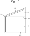
- the retractable blind assembly is configured to move between a retracted position (as illustrated schematically in Fig. 1A ), a top deployed position (as illustrated in Fig. 1B ), and a bottom deployed position (as illustrated in Fig. 1C ).
- the blind assembly shown in Fig. 1A-C comprises a head rail 100, a middle rail 200, and a bottom rail 300.
- the head rail 100 When mounted for use, the head rail 100 extends upwardly at an acute angle.
- the middle rail 200 is disposed between the head rail 100 and the bottom rail 300.
- the retractable blind assembly includes a top section with a covering material 10 extending between the head rail 100 and the middle rail 200.
- the middle rail 200 is configured to be pivotable between a retracted position (as shown in Fig. 1A ) and a top deployed position (as shown in Fig. 1B ).
- the middle rail 200 is pivotable with respect to the head rail 100 about a pivot center 201 that is adjacent to a lowermost end 110 of the head rail 100.
- the middle rail 200 In the retracted position, as illustrated in Fig. 1A , the middle rail 200 extends upwardly at an acute angle and is adjacent the head rail 100.
- the covering material 10 (not visible in Fig. 1A ) is retracted.
- the middle rail 200 In the top deployed position, as illustrated in Fig. 1B , the middle rail 200 extends horizontally.
- the head rail 100 extends upwardly at an acute angle to the horizontally extending middle rail 200.
- the covering material 10 of the top section is extended.
- the retractable blind assembly also includes a bottom section with a covering material 20 extending between the middle rail 200 and the bottom rail 300.
- the bottom rail 300 is configured to be movable vertically between the top deployed position (as shown in Fig. 1B ) and a bottom deployed position (as shown in Fig. 1C ).
- the top deployed position as illustrated in Fig. 1B
- the bottom rail 300 extends horizontally adjacent the middle rail 200.
- the covering material 20 in the bottom section is retracted.
- the bottom deployed position as illustrated in Fig. 1C
- the bottom rail 300 extends horizontally.
- the covering material 20 of the bottom section is fully extended.
- the bottom rail 300 is also configured to be movable between the top deployed position (as shown in Fig. 1B ) and the retracted position (as shown in Fig. 1A ). In the retracted position, as illustrated in Fig. 1A , the bottom rail 300 extends upwardly at an acute angle and is adjacent the middle rail 200.
- the head rail 100 is configured to be attached to a mounting structure, for example a wall, window frame or lintel, such that the head rail 100 is at a fixed position.
- the head rail 100 is configured to be attached at a head rail angle 101 to the horizontal.
- the head rail angle 101 is an acute angle.
- the covering material 10 of the top section is attached to and disposed between the head rail 100 and the middle rail 200.
- the covering material 20 of the bottom section is attached to and disposed between the middle rail 200 and the bottom rail 300.
- the covering material of the top and bottom sections 10, 20 is fully deployed, for example to cover a window, rather than being retracted, for example to expose the window.
- the covering material 10 of the top section is configured to be deployed by lowering the middle rail 200 and the bottom rail 300 together. In the top deployed position, an end of the middle rail 220, farthest from the pivot center 201 in a longitudinal direction of the middle rail 200, is separated from the uppermost end 120 of the head rail 100.
- the retractable blind assembly is configured such that, when the covering material 10 of the top section is deployed, an upper edge of the covering material 10 is at the head rail angle 101 and a lower edge of the covering material 10 is horizontal.
- the covering material 20 of the bottom section is configured to be deployed by lowering the bottom rail 300 such that the bottom rail 300 is separated from the middle rail 200.
- the retractable blind assembly is configured such that, when the covering material 20 of the bottom section is deployed, an upper edge of the covering material 20 is horizontal and a lower edge of the covering material 20 is horizontal.
- the blind assembly transitions from the retracted position (such as shown in Fig. 1A ) to the bottom deployed position (otherwise referred to as a fully deployed position, such as is shown in Fig. 1C and Fig. 2-4 ) in two respective stages.
- the first deployment stage Fig. 1A to Fig. 1B
- the covering material 10 of the top section is deployed and in the second deployment stage the covering material 20 of the bottom section is deployed ( Fig. 1B to Fig. 1C ).
- the blind assembly transitions from the bottom deployed position (such as is shown in Fig. 1C and Fig. 2-4 ) to the retracted position (such as shown in Fig. 1A ) in two respective stages.
- the covering material 20 of the bottom section is retracted and in the second retraction stage the covering material 10 of the top section is retracted ( Fig. 1B to Fig. 1A ). In this manner, the situation where the covering material 10 of the top section is in a partially deployed state while the covering material 20 of the bottom section is also partially or fully deployed is avoided.
- the first deployment stage is completed such that the middle rail and the bottom rail extend horizontally before the second deployment stage of deployment begins. Otherwise, there is a risk that the covering material of the blind will fail to deploy or that the deployment will be incomplete. In particular, there is a risk that the bottom rail will be lowered at an acute angle to the horizontal. In such a scenario, the covering material can become wrinkled and distorted. Furthermore, the bottom rail and/or middle rail may impact against the surrounding architecture (such as the window frame of the window the blind assembly is disposed to cover). This could lead to damage to the retractable blind assembly or the surrounding architecture.
- a retractable blind assembly may be embodied for example as illustrated schematically in Fig. 2-4 .
- the retractable blind assembly for example as illustrated in Fig. 2-4 , has a single lift cord 30 configured to raise and lower the bottom rail 300 to retract and extend the covering material 10, 20.
- the single lift cord 30 is routed in a single lift cord loop from the head rail 100, through the middle rail 200 and the bottom rail 300, and back to the head rail 100.
- the single lift cord loop is preferably configured such that the single lift cord 30 is supports the entire weight of the bottom rail 300.
- This lift cord routing arrangement may provide the advantage that the middle rail and the bottom rail move together between the retracted position and the top deployed position and become level in the top deployed and bottom deployed positions.
- the middle rail and the bottom rail may not separate as the middle and bottom rails move between being set at an acute angle in the retracted position and being horizontal in the top deployed position.
- the bottom rail is not fixed to the single lift cord at any point, its angle relative to the horizontal may continuously adjust and, as it moves, it may self-level. Therefore, the bottom rail will self-level to the horizontal in the top deployed and bottom deployed positions.
- the bottom rail may remain horizontal as it moves between a top deployed position and a bottom deployed position.
- the middle and bottom rails can become separated during deployment of the top section, before the middle rail has reached the horizontal.
- the relative lengths of the lift cords must be carefully set to ensure that one end of the middle and/or bottom rail does not raise or lower faster than the other end of the bottom rail, resulting in the rail not being level.
- the retractable blind assembly for example as shown in Fig. 2-4 , may therefore have the advantage of reliably keeping the middle and bottom rails level.
- the retractable blind assembly has a head rail 100 that can be mounted at any acute angle to the horizontal from a range of angles.
- the head rail 100 is suitable for mounting at any angle to conform to an upper edge of an architectural feature (for example a window) having an upper edge which is at an acute angle to the horizontal.
- an architectural feature for example a window
- the blind assembly may be easily mounted at the desired angle and the middle and bottom rails will lower correctly, in stages, without the need to adapt the lift cord to account for the mounting angle of the head rail.
- the retractable blind assembly is configured such that the single lift cord 30 is extended to lower the bottom rail 300 to move the retractable blind assembly between the retracted position and the top deployed position, and to move the retractable blind assembly between the top deployed position and the bottom deployed position.
- the retractable blind assembly is configured such that the single lift cord 30 is retracted to raise the bottom rail 300 to move the retractable blind assembly between the bottom deployed position and the top deployed position, and to move the retractable blind assembly between the top deployed position and the retracted position while permitting continuous adjustment of the angle of the bottom rail 300.
- the lift cord loop is configured to force the bottom rail 300 towards the head rail 100 when the lift cord 30 is retracted towards the head rail 100.
- the middle rail 200 remains stationary and the distance between the bottom rail 300 and the middle rail 200 is reduced until the top deployed position is reached.
- the distance between the bottom rail 300 and the middle rail 200 is a minimum distance. In this position, the bottom rail 300 and the middle rail 200 indirectly abut each other, via the retracted covering material 10 of the top section.
- the routing of the single lift cord 30 may be such as to raise the bottom rail 300 between the bottom deployed position and the top deployed position without exerting an upward force on the middle rail 200. This may advantageously reduce the risk that the middle rail 200 starts to raise before the bottom rail 300 is raised to the top deployed position.
- the routing of the single lift cord 30 may be such as to raise the bottom rail 300 between the top deployed position and the retracted position, while the bottom rail 300 exerts an upwards force on the middle rail 200 such that the middle rail 200 is raised into the retracted position due to the single lift cord 30 being retracted to raise the bottom rail 300. This efficient use of a single lift cord keeps the assembly simple with relatively few moving cords.
- the single lift cord 30 may be routed through the middle rail 200 such that the single lift cord 30 has inflection points associated with the middle rail 200.
- the single lift cord 30 may also be routed through the bottom rail 300 such that the single lift cord 30 has inflection points associated with the bottom rail 300.
- the single lift cord 30 has inflection points on the middle and bottom rails.
- the single lift cord having an inflection point associated with a rail may change direction at a position on a surface of the corresponding rail or inside the corresponding rail.
- the single lift cord having an inflection point associated with a rail may change direction at a position adjacent the corresponding rail.
- inflection points occur in the cord at locations where the cord in the routing changes direction, e.g. or turns a corner so to speak. Such a change of direction results in a bend in the cord which is called an inflection point.
- the blind assembly may comprise a plurality of points of contact between the single lift cord and the middle rail and/or the bottom rail.
- the single lift cord may be routed such that where the cord changes direction it creates a point of contact between the lift cord and the middle rail and/or the bottom rail. So, there may be a point of contact between the single lift cord and the corresponding rail where the direction of the single lift cord route is changed and an inflection point is created.
- the blind assembly may comprise cord guides, such as cord holes or cord loops to guide the cord along its route and/or protect the cord from wear and abrasions by the cord moving when the blind is lifted and/or lowered.
- the single lift cord may be routed straight through a cord guide without changing the routing direction or may be routed through a cord guide to change the direction of the single lift cord at that cord guide and create an inflection point.
- the cord guides may comprise the points of contact between the single lift cord and the rails. Note that the cord may also be routed through a cord guide without changing direction.
- the single lift cord 30 is preferably routed such that the single lift cord 30 has fewer inflection points associated with the middle rail 200 than associated with the bottom rail 300.
- the single lift cord 30 is preferably routed such that, when moving the bottom rail 300 between the retracted position and top deployed position, the friction exerted on the single lift cord 30 by the points of contact between the single lift cord 30 and the bottom rail 300 is greater than the friction exerted on the single lift cord by the points of contact between the single lift cord 30 and the middle rail 200.
- the single lift cord 30 may be routed through cord guides, such as cord holes or cord hoops. The single lift cord may contact the cord guides at the point of contact where the direction of the cord is changed and where inflection points are created.
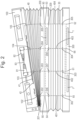
- the single lift cord 30 is preferably routed such that the single lift cord 30 has four inflection points 61, 62, 65, 66 associated with the bottom rail 300 and the single lift cord 30 is preferably routed such that the single lift cord 30 has two inflection points 63, 64 associated with the middle rail 200.
- Routing the single lift cord via points of contact, provided to contact the single lift cord to change the route of the cord at these inflection points, may conveniently provide the desired difference between the friction exerted by points of contact between the single lift cord and the bottom rail and the friction exerted by points of contact between the single lift cord and the middle rail, without leading to an excessive overall amount of friction exerted on the single lift cord.
- the single lift cord loop 30 may be routed from the head rail 100 down to a first inflection point 61 of the single lift cord, associated with the bottom rail 300, for example as shown in Fig. 2-4 .
- the single lift cord 30 is re-directed in a longitudinal direction along the bottom rail 300 towards a second inflection point 62 of the single lift cord, associated with the bottom rail 300.
- the single lift cord 30 is re-directed in an upward direction towards a third inflection point 63 of the single lift cord, associated with the middle rail 200.
- the single lift cord 30 is re-directed in a longitudinal direction along the middle rail 200 towards a fourth inflection point 64 of the single lift cord, associated with the middle rail 200.
- the single lift cord 30 is re-directed in a downward direction towards a fifth inflection point 65 of the single lift cord, associated with the bottom rail 300.
- the single lift cord 30 is re-directed in a longitudinal direction along the bottom rail 300 towards a sixth inflection point 66 of the single lift cord, associated with the bottom rail 300.
- the single lift cord 30 is re-directed in an upward direction to the head rail 100.
- the cords in a blind it is preferred for the cords in a blind to be protected from outside influences and interference, so the cords preferably are routed to an inside of a rail.
- the head rail 100, middle rail 200 and bottom rail are depicted as hollow profiles having cord guides (e.g., cord holes or cord loops) 102-105, 202-209, 302-305.
- Each rail may be a single or multiple part profile.
- the cord holes are provided with a grommets. These grommets prevents the cords from being damaged by sharp edges of the cord holes.
- each of the bottom rail and the middle rail may comprise a plurality of cord holes.
- the single lift cord may be routed through the cord holes and re-directed along each of the bottom rail and the middle rail between inflection points.
- the single lift cord may also be routed through the cord holes without the single lift cord changing direction, such as for example when the cord is routed straight up or down.
- Inflection points are created in the single lift cord adjacent the cord holes through which the single lift cord is routed when the cord is re-directed from a straight up or down routing to a longitudinal routing along the middle or bottom rail. Adjacent the cord hole means that the lift cord is re-directed after it has passed through the cord hole.
- the single lift cord 30 is routed from a first cord spool 81 out of head rail 100 through a cord hole 103, passes through the top section covering material 10, and into middle rail 200 via cord hole 203. From cord hole 203 the lift cord 30 is directed straight down to cord hole 207 which is opposite cord hole 203. The lift cord then passes through the bottom section covering material 20 and into the bottom rail 300 through cord hole 303. From cord hole 303 the lift cord is routed towards cord hole 305 which is distanced to the right of it, in a longitudinal direction along the bottom rail 300. This routing creates first inflection point 61 adjacent cord hole 303. The lift cord then passes through cord hole 305, through the bottom shade portion and upwards towards cord hole 209.
- This routing creates second inflection point 62 adjacent cord hole 305.
- the single lift cord is then routed through cord hole 209 and towards cord hole 206 which is distanced to the left of it, in a longitudinal direction along the middle rail 200.
- This routing creates third inflection point 63 adjacent cord hole 209.
- the single lift cord is then directed downward from cord hole 206 through the bottom section covering material 20 towards cord hole 302.
- fourth inflection point 64 is created adjacent cord hole 206.
- From the cord hole 302 the single lift cord is directed in a longitudinal direction along the bottom rail towards cord hole 304 which is located between cord holes 303 and 305.
- fifth inflection point 65 is created adjacent cord hole 302.
- cord hole 304 From cord hole 304 the lift cord is directed upwards through the bottom section covering material, and into the middle rail 200 via cord hole 208 of middle rail 200. Thus, sixth inflection point 66 is created adjacent cord hole 304. From cord hole 208, the single lift cord 30 is directed straight up to cord hole 204 which is opposite cord hole 208. The single lift cord then passes through the top section covering material 10 and into the head rail 100 through cord hole 104 and to a second cord spool 82.
- the single lift cord 30 is routed from a first cord spool 81 out of head rail 100 through a cord hole 103, passes through the top section covering material 10, and into middle rail 200 via cord hole 203. From cord hole 203 the lift cord 30 is directed straight down to cord hole 207 which is opposite cord hole 203. The lift cord then passes through the bottom section covering material 20 and into the bottom rail 300 through cord hole 303. From cord hole 303 the lift cord is routed towards cord hole 302 which is distanced to the left of it, in a longitudinal direction along the bottom rail 300. This routing creates first inflection point 61 adjacent cord hole 303.
- the lift cord then passes through cord hole 302, through the bottom section covering material 20 and upwards towards cord hole 206 of the middle rail 200.
- This routing creates second inflection point 62 adjacent cord hole 302.
- the single lift cord is then routed through cord hole 206 and towards cord hole 209 which is distanced to the right of it, in a longitudinal direction along the middle rail 200.
- This routing creates third inflection point 63 adjacent cord hole 206.
- From cord hole 209 the single lift cord is routed downwards through the bottom section covering material towards cord hole 305 of the bottom rail 300.
- fourth inflection point 64 is created adjacent cord hole 209.
- From cord hole 305 the lift cord is directed in a longitudinal direction along the bottom rail to cord hole 304 and fifth inflection point 65 is created adjacent cord hole 305.
- cord hole 304 single lift cord is then directed up from cord hole 304, through the bottom section covering material 20, and into the middle rail 200 via cord hole 208. And sixth inflection point 66 is created adjacent cord hole 304. From cord hole 208, the single lift cord 30 is directed straight up to cord hole 204 which is opposite cord hole 208. The single lift cord then passes through the top section covering material 10 and into the head rail 100 through cord hole 104 and to a second cord spool 82.
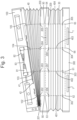
- the single lift cord 30 is routed from a first cord spool 81 out of head rail 100 through a cord hole 103, passes through the top section covering material 10, and into middle rail 200 via cord hole 203. From cord hole 203 the lift cord 30 is directed straight down to cord hole 207 which is opposite cord hole 203. The lift cord then passes through the bottom section covering material 20 and into the bottom rail 300 through cord hole 303. From cord hole 303 the lift cord is routed towards cord hole 302 which is distanced to the left of it, in a longitudinal direction along the bottom rail 300. This routing creates first inflection point 61 adjacent cord hole 303.
- the lift cord then passes through cord hole 302, through the bottom section covering material 20 and upwards towards cord hole 206.
- This routing creates second inflection point 62 adjacent cord hole 302.
- the single lift cord is then routed through cord hole 206 and towards cord hole 209 which is distanced to the right of it, in a longitudinal direction along the middle rail 200.
- This routing creates third inflection point 63 adjacent cord hole 206.
- From cord hole 209 the lift cord is routed downwards through the bottom section covering material and towards cord hole 305.
- From cord hole 305 the single lift cord 30 is routed towards cord hole 303 and fifth inflection point 65 is created adjacent cord hole 305.
- cord hole 303 the lift cord 30 is routed upwards through the bottom section covering material 20, and into the middle rail via cord hole 207. This creates sixth inflection point 66 of this cord routing adjacent cord hole 303. From cord hole 207, the single lift cord 30 is directed straight up to cord hole 203 which is opposite cord hole 207. The single lift cord then passes through the top section covering material 10 and into the head rail 100 through cord hole 103 and to a second cord spool 82.
- the single lift cord 30 is routed such that the first inflection point 61 of the single lift cord is associated with the bottom rail 300 between the fifth inflection point 65 and the sixth inflection point 66 in a longitudinal direction of the bottom rail 300.
- the single lift cord is routed such that the sixth inflection point 66 is associated with the bottom rail 300 between the first inflection point 61 and the second inflection point 62 in a longitudinal direction of the bottom rail 300.
- This arrangement may have the benefit that the distance between the first inflection point 61 and the second inflection point 62 and the distance between the fifth inflection point 65 and the sixth inflection point 66 can be greater than the corresponding distances in the arrangement shown in Fig. 3 .
- This increased distance between inflection points can provide the benefit of a more stable support for the bottom rail 300.
- the single lift cord is routed such that the first inflection point 61 of the single lift cord is associated with the bottom rail 300 between the second inflection point 62 and the sixth inflection point 66 in a longitudinal direction of the bottom rail 300.
- the single lift cord 30 is routed such that the sixth inflection point 66 is associated with the bottom rail 300 between the first inflection point 61 and the fifth inflection point 65 in a longitudinal direction of the bottom rail 300.
- This arrangement has the benefit that the first inflection point 61 and the second inflection point 62 may be adjacent to each other.
- the fifth inflection point 65 and the sixth inflection point 66 may be adjacent to each other.
- the single lift cord 30 is not routed to cross over itself as many times as it does in the arrangement shown in Fig. 2 . In places where the cord crosses its own route there is a possibility of the cord can contact itself leading to abrasion and possibly damage to the cord.
- the single lift cord is routed such that it has inflection points associated with the middle rail 200 which are preferably at symmetrical positions around the center of the middle rail 200 in a longitudinal direction of the middle rail 200.
- the single lift cord is routed such that it has inflection points associated with the bottom rail 300 which are preferably at symmetrical positions around the center of the bottom rail 300 in a longitudinal direction of the bottom rail 300.
- the covering material 10, 20 of the top section and the bottom section may define a series of cord holes.
- the lift cord may be routed between the head rail 100 and the bottom rail 200 through the cord holes in the covering material 10 of the top section.
- the lift cord may be routed between the middle rail 200 and the bottom rail 300 through the cord holes in the covering material 20 of the bottom section.
- the lift cord can aid in keeping the covering material 10, 20 properly aligned.
- the lift cord can act to keep the covering material 10 in alignment with the plane defined by the head rail 100 and the middle rail 200 in the top deployed position, and the bottom deployed position.
- the lift cord can act to keep the covering material 20 in alignment with the plane defined by the middle rail 200 and the bottom rail 300 in the bottom deployed position. In this way the risk of the covering material billowing out is reduced.
- the cord holes are preferably disposed on the covering material 10 of the top section such that, when the covering material 10 of the top section is deployed (such as in the top deployed and bottom deployed positions), the cord holes are aligned with each other in columns following the route of the lift cord between the head rail 100 and the middle rail 200.
- the cord holes are preferably disposed on the covering material 20 of the bottom section such that, when the covering material 20 of the bottom section is deployed (such as in the bottom deployed position), the cord holes are aligned with each other in columns following the route of the lift cord between the middle rail 200 and the bottom rail 300.
- Fig. 4 illustrates an alternative arrangement of the retractable blind assembly.
- the blind assembly arrangement of Fig. 4 is depicted in the bottom deployed position.
- the blind assembly arrangement in Fig. 4 is the same as that of Fig. 3 except that the single lift cord 30 is routed from the sixth inflection point 66 of the single lift cord to the head rail 100 via cord guide 207.
- the single lift cord 30 is also routed from the head rail 100 to the first inflection point 61 of the single lift cord via cord guide 207 on the middle rail 200. Consequently, in the arrangement shown in Fig. 4 , instead of the single lift cord bring routed through two separate cord guides 207, 208, in this example the single lift cord is routed through a single cord guide, the first cord guide 207. This reduces the overall number of cord guides, or cord holes, used.
- the cord guide 207 is preferably positioned at the center of the middle rail 200 in a longitudinal direction of the middle rail 200. With this arrangement, the single lift cord 30 is extended/retracted through a central location on the rails.
- the covering material 10, 20 of the top section and the bottom section may be provided with cord hoops attached to the covering material 10, 20.
- the single lift cord 30 may be routed through the cord hoops of the covering material 10, 20 to route the lift cord loop between the head rail 100 and the middle rail 200 and between the middle rail 200 and the bottom rail 300.
- the retractable blind assembly preferably comprises a cord deployment system configured to extend and retract the single lift cord 30.
- the cord deployment system may be attached to the head rail 100.
- At least a first end of the single lift cord 30 is connected to the cord deployment system such that the cord deployment system can be operated to extend and retract the single lift cord 30.
- a second end of the lift cord is also attached to the cord deployment system such that both ends of the single lift cord can be extended from or retracted into the head rail.
- the cord deployment system is disposed away from the head rail 100 and the single lift cord 30 is routed to the cord deployment system such that the single lift cord has inflection points on the head rail 100 to guide the lift cord to/from the cord deployment system.
- the cord deployment system may comprise any known system suitable for extending and retracting a lift cord.
- the cord deployment system may comprise a pulley system or a spool assembly.
- the cord deployment system is preferably attached to the head rail 100 such that the single lift cord 30 is retracted to pull the bottom rail 300 towards the head rail 100.
- the cord deployment system is preferably attached to the head rail 100 such that the single lift cord 30 is extended to lower the bottom rail 300 away from the head rail 100.
- the part of the cord deployment system to which the single lift cord 30 is attached at a position closer to the center of the head rail 100, in a longitudinal direction of the head rail 100, than the ends 110, 120 of the hear rail 111.
- the cord deployment system may comprise a spool assembly comprising a single spool.
- a first end of the single lift cord is attached to the single spool and a second end of the single lift cord is connected at a fixed point in the head rail.
- the first end and the second end of the single lift cord 30 may both be attached to opposite ends of the single spool.
- the cord deployment system is a spool assembly comprising a first spool 81 and a second spool 82, as shown for example in Fig. 2-4 .
- the first end of the single lift cord 30 is attached to the first spool and the second end of the lift cord 30 is attached to the second spool.
- the first spool 81 and the second spool 82 are configured to rotate to extend and retract the single lift cord 30.
- each of the spool takes-up approximately half of the single cord. Consequently, the blind comprising two spools can be retracted/deployed twice as fast as the blind comprising a single spool, with the same rotational speed of the spool.
- the first spool 81 and the second spool 82 may, for example, be configured to rotate in the same direction as each other.
- the first spool 81 and the second spool 82 are configured to rotate in a first direction to extend the single lift cord 30 and are configured to rotate in a second direction, opposite to the first direction, to retract the single lift cord 30.
- the first spool 81 and the second spool 82 are configured to rotate at the same rotational speed. This helps to provide even lowering of the bottom rail 300 between the top deployed position and the bottom deployed position.
- the spool assembly preferably comprises a shaft 83, wherein the first spool 81 and the second spool 82 are configured to rotate with the shaft 83.
- the cord deployment system is preferably motorised.
- the weight of the bottom rail 300 is optionally greater than the weight of the middle rail 200.
- the bottom rail 300 may comprise a material with a density greater than 4,000 kg/m 3 . In this way, the relatively heavy bottom rail 300 is more readily lowered than if the bottom rail were lighter.
- the center of mass of the bottom rail 300 is in the center of the bottom rail 300 in a longitudinal direction of the bottom rail 300.
- the bottom rail 300 may comprise one or more weighting components 1. These weighting components 1 can be used to increase the weight of the bottom rail 300 and to ensure the center of mass of the bottom rail 300 is in the desired location. Furthermore, with this arrangement, the bottom rail 300 is more easily maintained in a horizontal position when moving between the top deployed position and the bottom deployed position.
- the center of mass of the middle rail 200 is preferably at a location further from the end 210 of the middle rail 200 that is adjacent to the pivot center 201 than the opposite end 220 of the middle rail 200 in a longitudinal direction of the middle rail 200. This can be desirable in situations when the end 210 of the middle rail 200 does not need to travel as far as the opposite end 220 of the middle rail 200 to reach its intended position. For example, with this arrangement, the middle rail 200 more readily deploys from the retracted position to the top deployed position.
- the middle rail 200 may comprise a weighting component 1.
- the weighting component 1 is preferably disposed at a location further from the end 210 of the middle rail 200 that is adjacent to the pivot center 201 than the opposite end 220 of the middle rail 200 in a longitudinal direction of the middle rail 200.
- the center of mass location of the middle rail 200 can be tailored to the requirements of the retractable blind assembly.
- the mass or position of the weighting component may be adapted depending on the length and/or the angle of the hear rail.
- the retractable blind assembly optionally further comprises a guide cord 40, for example as shown in Fig. 2-4 .
- the guide cord 40 is routed in a guide cord loop from the head rail 100, through the middle rail 200, and back to the head rail 100.
- the guide cord loop comprises a passive cord tensioner 41.
- the passive cord tensioner 41 is configured to release the guide cord 40 as the middle rail 200 moves away from the head rail 100 and to retract the guide cord 40 as the middle rail 200 moves toward the head rail 100. In this way, the passive cord tensioner 41 is configured to keep the guide cord loop taut.
- the covering material 10 of the top section may define a series of cord holes.
- the guide cord loop may be routed between the head rail 100 and the bottom rail 200 through the cord holes in the covering material 10 of the top section.
- a taut guide cord can aid in keeping the covering material 10 properly aligned.
- the guide cord can act to restrict movement of the covering material 10 to keep it in alignment with the plane defined by the head rail 100 and the middle rail 200 in the top deployed position, and the bottom deployed position. In this way, the guide cord can reduce the likelihood of the covering material billowing.
- the passive cord tensioner may be any known device suitable for keeping a cord loop taut.
- the passive cord tensioner 41 preferably comprises a spring.
- the spring may be configured to extend to increase the length of the guide cord loop as the middle rail 200 is lowered from the retracted position to the top deployed position.
- the spring may be configured to contract to decrease the length of the guide cord loop as the middle rail 200 is raised from the top deployed position to the retracted position. In this way, a spring may be used to keep the guide cord loop taut.
- the passive cord tensioner 41 comprises a spring and a spring end stop 42.
- the blind is shown in the bottom deployed position, with the middle rail 200 level.
- the spring is at its maximum length and abuts a spring end stop 42 disposed on the upper rail 100.
- the spring is configured to lengthen as the blind moves from the retracted position to the top deployed position.
- the passive cord tensioner is configured such that the spring will abut the spring end stop 42 when the blind reaches the top deployed position. Consequently, the guide cord can stop the middle rail from descending lower than is desired.
- the guide cord and passive cord tensioner may be configured to support the middle rail once it reaches the horizontal, such that the end of the middle rail opposite the end proximate the pivot center does not drop too low.
- the guide cord 40 is preferably routed through the middle rail 200 such that the guide cord 40 has inflection points 90 associated with the middle rail 200. As shown in the examples of Fig. 2-4 , the guide cord 40 is optionally routed through the head rail 100 such that the guide cord 40 has inflection points 91 associated with the head rail 100. Alternatively, the guide cord may be attached to the head rail 100 or the passive cord tensioner 41 without being routed such that the guide cord has inflection points associated with the head rail 100.
- the blind assembly may comprise a plurality of points of contact between the guide cord and the head rail and/or the middle rail.
- the guide cord may be routed such that it is configured to contact the points of contact.
- a first guide cord routed between the head rail and the middle rail closer to the opposite end of the rails than the end of the rails proximate to the pivot center (in a longitudinal direction of the rail).
- the first guide cord is preferably connected to the passive cord tensioner.
- Providing only the first guide cord in accordance with this arrangement is particularly suitable for narrow blind assemblies, with relatively short rails.
- a second guide cord there may be provided a second guide cord.
- the second guide cord is routed between the head rail and the middle rail at an end of the rails closer to the pivot center than to the opposite end of the rail (in a longitudinal direction of the rail).
- a second cord tensioner is attached to the head rail and the second guide cord is connected to the second cord tensioner.
- the guide cord 40 is routed from passive cord tensioner 41 out of head rail 100 through a cord hole 105. This routing may create an inflection point 90 adjacent cord hole 105.
- the guide cord 40 then passes through the top section covering material 10, and into middle rail 200 via cord hole 205. From cord hole 205 the guide cord 40 is directed to the left in a longitudinal direction of the middle rail 200 towards cord hole 202. This routing creates an inflection point 90 adjacent cord hole 205.
- the guide cord 40 is then routed through guide hole 202 and upwards towards guide hole 102. This routing creates another inflection point 90 adjacent cord hole 202.
- the guide cord 40 is then routed through the top covering material and back to the head rail 100 via cord hole 102.
- the covering material 10 of the top section may be provided with cord hoops attached to the covering material 10.
- the guide cord may be routed through the cord hoops of the covering material 10 to route the guide cord loop between the head rail 100 and the middle rail 200.
- the covering material cannot billow out because the covering material 10 is retracted.
- the arrangement keeping the guide cord taut is nonetheless potentially beneficial in this position because it may aid in keeping the guide cord from becoming slack.
- a slack guide cord could look unsightly to the user. More importantly, a slack guide cord could have the unwanted effect of becoming tangled with the lift cord or around the middle or bottom rail, which could hamper deployment of the blind. Consequently, it can be advantageous to have the guide cord kept taut.
- the lift cord loop tightens, raising the bottom rail.
- the tightening of the lift cord loop biases the bottom rail and the middle rail towards each other until, in the top deployed position, the middle rail and the bottom rail are a minimum distance apart.
- Further retraction of the single lift cord acts to pull up the bottom rail, which supports the middle rail such that the middle rail and the bottom rail move up together, and do not separate, from a top deployed position to a retracted position.
- the bottom rail which is being supported by the single lift cord is lowered.
- the middle rail is supported by the bottom rail as the single lift cord is extended to move the blind assembly from the retracted position to the top deployed position.
- the blind assembly optionally further comprises a guide cord which may be configured to support the middle rail in the top deployed position such that the middle rail is not able to move to a position lower than the intended top deployed position.
- the guide cord loop is configured to extend between the head and middle rails, such that the middle rail is able to be lowered to the top deployed position.
- the friction exerted on the single lift cord 30 by the points of contact between the single lift cord 30 and the middle and bottom rails may be greater than the friction exerted on the guide cord 40 moving in the guide cord loop.
- the difference between the friction exerted on the guide and lift cords may keep the middle rail from becoming separated from the bottom rail until the top deployed position is reached.
- the total number of inflection points 61-66 the single lift cord 30 has associated with the middle rail 200 and bottom rail 300 is greater than the total number of inflection points 90, 91 the guide cord loop 40 has.
- the friction exerted on single lift cord 30 by points of contact at inflection points 61-66 associated with the middle and bottom rails may be greater than the friction exerted on the guide cord 40 moving in the guide cord loop.
- the friction exerted on the single lift cord 30 by the points of contact at inflection points 61-66 associated with the middle and bottom rails is also greater than the total of the friction exerted on the guide cord 40 and any tension force exerted by the passive cord tensioner 41 on the guide cord 40 moving in the guide cord loop.
- the covering material 10 in the top section has a generally triangular shape with an unattached short apex about the pivot center 201 and an opposite, unattached, long side when the covering material 10 is extended.
- the unattached, long side is straight when the covering material 10 is extended (as shown in Fig. 1C and Fig. 2-4 ).
- covering material 20 in the bottom section may have a generally rectangular shape.
- the retractable blind assembly may be a stacking blind.
- the covering material 10, 20 may be any type of suitable blind covering material for a stacking blind, for example the blind covering material may comprise pleated hanging blind coverings, cellular blind coverings, slatted blind coverings or folding blind coverings.
- All directional references e.g., proximal, distal, upper, lower, upward, downward, left, right, lateral, longitudinal, front, back, top, bottom, above, below, vertical, horizontal, radial, axial, clockwise, counterclockwise, and/or the like
- proximal, distal, upper, lower, upward, downward, left, right, lateral, longitudinal, front, back, top, bottom, above, below, vertical, horizontal, radial, axial, clockwise, counterclockwise, and/or the like are only used for identification purposes to aid the reader's understanding of the present disclosure, and / or serve to distinguish regions of the associated elements from one another, and do not limit the associated element, particularly as to the position, orientation, or use of this disclosure.
Applications Claiming Priority (1)
| Application Number | Priority Date | Filing Date | Title |
|---|---|---|---|
| GBGB2201279.3A GB202201279D0 (en) | 2022-02-01 | 2022-02-01 | Blind |
Publications (1)
| Publication Number | Publication Date |
|---|---|
| EP4219877A1 true EP4219877A1 (de) | 2023-08-02 |
Family
ID=80621189
Family Applications (1)
| Application Number | Title | Priority Date | Filing Date |
|---|---|---|---|
| EP23152695.5A Pending EP4219877A1 (de) | 2022-02-01 | 2023-01-20 | Einziehbare jalousieanordnung |
Country Status (2)
| Country | Link |
|---|---|
| EP (1) | EP4219877A1 (de) |
| GB (1) | GB202201279D0 (de) |
Citations (3)
| Publication number | Priority date | Publication date | Assignee | Title |
|---|---|---|---|---|
| EP0532036A2 (de) | 1991-09-13 | 1993-03-17 | KARL H. BLÖCKER GmbH & Co. | Faltenvorhang für eine trapezförmige Fläche |
| EP0599092A2 (de) * | 1992-11-23 | 1994-06-01 | VOSSLOH Decoration International GmbH | Zusammenfaltbarer Behang für eine Fenster- oder Türöffnung |
| EP1555382B1 (de) | 2004-01-13 | 2007-08-22 | Hunter Douglas Industries B.V. | Zurückziehbare Jalousie |
-
2022
- 2022-02-01 GB GBGB2201279.3A patent/GB202201279D0/en not_active Ceased
-
2023
- 2023-01-20 EP EP23152695.5A patent/EP4219877A1/de active Pending
Patent Citations (4)
| Publication number | Priority date | Publication date | Assignee | Title |
|---|---|---|---|---|
| EP0532036A2 (de) | 1991-09-13 | 1993-03-17 | KARL H. BLÖCKER GmbH & Co. | Faltenvorhang für eine trapezförmige Fläche |
| EP0532036B1 (de) * | 1991-09-13 | 1996-02-14 | KARL H. BLÖCKER GmbH & Co. | Faltenvorhang für eine trapezförmige Fläche |
| EP0599092A2 (de) * | 1992-11-23 | 1994-06-01 | VOSSLOH Decoration International GmbH | Zusammenfaltbarer Behang für eine Fenster- oder Türöffnung |
| EP1555382B1 (de) | 2004-01-13 | 2007-08-22 | Hunter Douglas Industries B.V. | Zurückziehbare Jalousie |
Also Published As
| Publication number | Publication date |
|---|---|
| GB202201279D0 (en) | 2022-03-16 |
Similar Documents
| Publication | Publication Date | Title |
|---|---|---|
| EP2402544B1 (de) | Rollo mit geschleifter Rollobahn zur Opazitätseinstellung | |
| EP2131008B1 (de) | Fensterabdeckung | |
| JP5937296B2 (ja) | 横型ブラインド | |
| AU2003201365B2 (en) | Bottom-up/top-down retractable cellular shade | |
| AU2011240377B2 (en) | Conical cord-winding spool with circumferential steps | |
| US5860464A (en) | Retractable blind or shade assembly | |
| JP6144306B2 (ja) | 横型ブラインド | |
| EP2149667B1 (de) | Fensterabdeckung mit mindestens einem verformbaren Anschluss | |
| JP5852957B2 (ja) | 壁の開口部または窓を覆うための巻取装置 | |
| EP1555382B1 (de) | Zurückziehbare Jalousie | |
| EP4219877A1 (de) | Einziehbare jalousieanordnung | |
| EP1849935A2 (de) | Automatisches Abdeckelement, insbesondere für Gruben von Mechanikwerkstätten und dergleichen | |
| JP2014218827A (ja) | 横型ブラインド | |
| JP6082088B2 (ja) | 横型ブラインド | |
| CN116234971A (zh) | 用于板条帘的具有绳护罩布置的梯带组件 | |
| CN106193974A (zh) | 百叶窗的升降装置 | |
| JP3795444B2 (ja) | ブラインド用の昇降コード巻取装置 | |
| EP3530864B1 (de) | Montagestation von jalousien mit vollständigen stützleitern | |
| JP4302815B2 (ja) | ブラインド | |
| KR200340806Y1 (ko) | 셔터조립체 | |
| JP3695700B2 (ja) | 日射遮蔽装置の遮蔽材昇降装置 | |
| WO1997034069A1 (en) | Window screen | |
| JP3844484B2 (ja) | ローマンシェード | |
| PL212388B1 (pl) | Roleta zewnętrzna | |
| EP1518996A1 (de) | Gehäuse für Rollladen |
Legal Events
| Date | Code | Title | Description |
|---|---|---|---|
| PUAI | Public reference made under article 153(3) epc to a published international application that has entered the european phase |
Free format text: ORIGINAL CODE: 0009012 |
|
| STAA | Information on the status of an ep patent application or granted ep patent |
Free format text: STATUS: THE APPLICATION HAS BEEN PUBLISHED |
|
| AK | Designated contracting states |
Kind code of ref document: A1 Designated state(s): AL AT BE BG CH CY CZ DE DK EE ES FI FR GB GR HR HU IE IS IT LI LT LU LV MC ME MK MT NL NO PL PT RO RS SE SI SK SM TR |
|
| RIN1 | Information on inventor provided before grant (corrected) |
Inventor name: LEEPEL, FREDERIK WILLEM Inventor name: FRANSSEN, JOHANNES ROBERTUS MARIA Inventor name: SCHUURS, VINCENT |
|
| STAA | Information on the status of an ep patent application or granted ep patent |
Free format text: STATUS: REQUEST FOR EXAMINATION WAS MADE |
|
| 17P | Request for examination filed |
Effective date: 20240202 |
|
| RBV | Designated contracting states (corrected) |
Designated state(s): AL AT BE BG CH CY CZ DE DK EE ES FI FR GB GR HR HU IE IS IT LI LT LU LV MC ME MK MT NL NO PL PT RO RS SE SI SK SM TR |