EP4219084A1 - Handgetragenes arbeitsgerät - Google Patents
Handgetragenes arbeitsgerät Download PDFInfo
- Publication number
- EP4219084A1 EP4219084A1 EP22154068.5A EP22154068A EP4219084A1 EP 4219084 A1 EP4219084 A1 EP 4219084A1 EP 22154068 A EP22154068 A EP 22154068A EP 4219084 A1 EP4219084 A1 EP 4219084A1
- Authority
- EP
- European Patent Office
- Prior art keywords
- front handle
- handle
- functional element
- working device
- housing
- Prior art date
- Legal status (The legal status is an assumption and is not a legal conclusion. Google has not performed a legal analysis and makes no representation as to the accuracy of the status listed.)
- Granted
Links
Images
Classifications
-
- B—PERFORMING OPERATIONS; TRANSPORTING
- B25—HAND TOOLS; PORTABLE POWER-DRIVEN TOOLS; MANIPULATORS
- B25F—COMBINATION OR MULTI-PURPOSE TOOLS NOT OTHERWISE PROVIDED FOR; DETAILS OR COMPONENTS OF PORTABLE POWER-DRIVEN TOOLS NOT PARTICULARLY RELATED TO THE OPERATIONS PERFORMED AND NOT OTHERWISE PROVIDED FOR
- B25F5/00—Details or components of portable power-driven tools not particularly related to the operations performed and not otherwise provided for
- B25F5/02—Construction of casings, bodies or handles
-
- H—ELECTRICITY
- H05—ELECTRIC TECHNIQUES NOT OTHERWISE PROVIDED FOR
- H05B—ELECTRIC HEATING; ELECTRIC LIGHT SOURCES NOT OTHERWISE PROVIDED FOR; CIRCUIT ARRANGEMENTS FOR ELECTRIC LIGHT SOURCES, IN GENERAL
- H05B3/00—Ohmic-resistance heating
- H05B3/02—Details
-
- A—HUMAN NECESSITIES
- A01—AGRICULTURE; FORESTRY; ANIMAL HUSBANDRY; HUNTING; TRAPPING; FISHING
- A01G—HORTICULTURE; CULTIVATION OF VEGETABLES, FLOWERS, RICE, FRUIT, VINES, HOPS OR SEAWEED; FORESTRY; WATERING
- A01G3/00—Cutting implements specially adapted for horticultural purposes; Delimbing standing trees
- A01G3/04—Apparatus for trimming hedges, e.g. hedge shears
- A01G3/047—Apparatus for trimming hedges, e.g. hedge shears portable
- A01G3/053—Apparatus for trimming hedges, e.g. hedge shears portable motor-driven
-
- A—HUMAN NECESSITIES
- A01—AGRICULTURE; FORESTRY; ANIMAL HUSBANDRY; HUNTING; TRAPPING; FISHING
- A01G—HORTICULTURE; CULTIVATION OF VEGETABLES, FLOWERS, RICE, FRUIT, VINES, HOPS OR SEAWEED; FORESTRY; WATERING
- A01G3/00—Cutting implements specially adapted for horticultural purposes; Delimbing standing trees
- A01G3/08—Other tools for pruning, branching or delimbing standing trees
- A01G3/085—Motor-driven saws for pruning or branching
- A01G3/086—Chain saws
-
- H—ELECTRICITY
- H05—ELECTRIC TECHNIQUES NOT OTHERWISE PROVIDED FOR
- H05B—ELECTRIC HEATING; ELECTRIC LIGHT SOURCES NOT OTHERWISE PROVIDED FOR; CIRCUIT ARRANGEMENTS FOR ELECTRIC LIGHT SOURCES, IN GENERAL
- H05B3/00—Ohmic-resistance heating
- H05B3/20—Heating elements having extended surface area substantially in a two-dimensional [2D] plane, e.g. plate-heater
- H05B3/34—Heating elements having extended surface area substantially in a two-dimensional [2D] plane, e.g. plate-heater flexible, e.g. heating nets or webs
-
- B—PERFORMING OPERATIONS; TRANSPORTING
- B27—WORKING OR PRESERVING WOOD OR SIMILAR MATERIAL; NAILING OR STAPLING MACHINES IN GENERAL
- B27B—SAWS FOR WOOD OR SIMILAR MATERIAL; COMPONENTS OR ACCESSORIES THEREFOR
- B27B17/00—Chain saws; Equipment therefor
- B27B17/0008—Means for carrying the chain saw, e.g. handles
Definitions
- the invention relates to a hand-held tool according to the preamble of claim 1.
- a hand-held working device is to be understood as meaning a working device whose intended use is carried out in particular by the operator. At particularly low temperatures, the handles of the tool are cold. In order to heat the handles, the use of heated grips is known.
- a handle heater can be designed as an electric handle heater, which is connected to a generator or a battery of the implement.
- the invention is therefore based on the object of specifying a hand-held tool that enables reliable operation of an electrical functional element arranged on a handle of the tool.
- the invention is based on the knowledge that the defect of the above-described functional element arranged on the handle, such as a heated grip, that occurs during operation of the implement can be attributed to a cable break in the connecting cable.
- the connection cable between the heated grips and the power source for the heated grips runs on the outside of the grip tube and is covered by a grip cover.
- branches from bushes, shrubs or trees, among other things can brush against the handle and damage the handle cover and the connecting cable.
- the hand-held tool comprises a housing, the housing having a top, a bottom, a first long side and a second long side, the top and bottom being connected to one another via the first long side and the second long side.
- the hand-held implement includes a drive motor arranged in the housing, the drive motor driving a tool arranged at the front end of the housing.
- the hand-held tool comprises a front handle and a rear handle, the front handle being designed as a loop handle and having a transverse section extending along the upper side of the housing and a side section extending along one of the two longitudinal sides of the housing.
- the front handle has a wall and an interior space enclosed by the wall, with the wall of the front handle comprising an inside facing the interior and an outside facing away from the interior.
- a first electrical functional element is arranged in the housing. At least one second electrical functional element is arranged on the outside of the front handle. The first electrical functional element is connected to the second functional element via at least one connecting cable. The at least one connection cable is arranged at least partially in the interior of the front handle in the area of the side section of the front handle.
- connection cable lies at least partially in the interior of the side section of the front handle and is thus protected by the front handle. Branches or the like can thus affect the front handle of the implement on the side section without damaging the connecting cable. Reliable operation of the second electrical functional element is thus ensured.
- the second electrical functional element is preferably designed as a heating foil.
- the second electrical functional element can also be designed as a sensor.
- the first electrical functional element is preferably an energy source for supplying the second functional element with electrical current.
- the energy source is preferably a generator.
- the energy source can also be a battery.
- the first electrical functional element can also be a control unit for processing data signals.
- the control unit is supplied with electrical current via a power source.
- an opening is provided on the wall of the front handle, in particular adjacent to the second electrical functional element, with the opening extending from the outside of the wall to the inside of the wall, with the at least one connecting cable from the outside of the wall runs through the opening into the interior of the handle.
- the opening is preferably provided with a grommet as edge protection.
- the grommet is preferably formed from an elastomer. This avoids chafing of the connecting cable at the opening.
- the holding section running horizontally is provided for holding the working device when the working device is being operated as intended.
- the horizontally running holding section is the area of the front handle that the operator grasps most frequently. If the opening were provided on the horizontally running holding section, the operator would feel it. The operator might perceive the opening as uncomfortable from an ergonomic point of view. In order to avoid this circumstance, the opening is provided outside the horizontally extending section.
- the transverse portion and the side portion of the front handle are connected to each other via a curved connecting portion, the opening in the side portion being provided adjacent to the connecting portion.
- An opening in the horizontal section of the front handle should be avoided for the reasons already described above.
- the opening should not be formed in the curved connecting portion either.
- An opening in the curve would be disadvantageous because of the high stress conditions and the associated weakening of the strength of the front handle.
- the connecting cable should be protected as much as possible by the front handle. Therefore, the opening in the side portion is preferably provided immediately adjacent to the curved portion of the front handle.
- the handle is preferably made of aluminum or plastic.
- the tool includes a grip tube insert for fastening the front handle to the housing of the tool, the grip tube insert being arranged in the interior of the handle at one end of the front handle.
- the grip tube insert has a cable duct for guiding the at least one connecting cable.
- connection point of the connection cable to the second functional element is relieved by the clamping on the grip tube insert.
- the connection cable can be subject to tensile stress. By clamping the connecting cable, the tensile load is already intercepted at the clamping point of the connecting cable. The connection of the connection cable and the second electrical functional element remains undamaged.
- connection cable runs from the outside of the wall of the front handle via the interior of the front handle through the connecting channel of the handle tube insert to one end of the front handle.
- the connection cable is therefore largely protected from external stresses in the front handle.
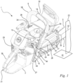
- a hand-held working device 1 which is designed as a "rear-handle” motor chain saw.
- the working device 1 can also be a "top-handle” motor chain saw.
- the implement can also be designed as a hedge trimmer, cut-off grinder, blower, brush cutter or the like.
- the working device 1 comprises a housing 2 and a drive motor 3 arranged in the housing 2.
- the drive motor 3 is designed as an internal combustion engine.
- the housing 2 has a top 26 , a bottom 27 , a first long side 28 and a second long side 29 .
- the top 26 and the bottom 27 are connected to one another via the two longitudinal sides 28 , 29 .
- the implement 1 includes a front handle 6 and a rear handle 36.
- the handles 6, 36 are used to hold and guide the implement 1.
- the rear handle is formed on a rear end 31 of the housing 2.
- a saw chain which is driven by the drive motor 3 is arranged so as to run around the guide rail 4 .
- the saw chain forms the tool 5 of the implement 1.
- the drive motor 3 drives a drive sprocket via a drive shaft (not shown).
- the drive sprocket is used to drive the saw chain, which is guided over the drive sprocket during operation.
- the working device 1 comprises a tensioning device 21 via which the guide rail 4 can be displaced forwards in the direction of its longitudinal axis 22 away from the drive sprocket.
- the longitudinal axis 22 runs centrally through the guide rail 4 approximately parallel to the horizontal floor 51.
- the term "roughly” is to be understood in such a way that the longitudinal axis 22 of the guide rail 4 is aligned with the Bottom 51 includes an angle of at most 15 °.
- the guide rail 4 has a longitudinal plane 23 which contains the longitudinal axis 22 and is perpendicular to the ground 51 when the implement 1 is parked on a level horizontal ground 51 .
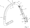
- the front handle 6 is designed as a loop handle.
- the front handle 6 is formed from a handle tube.
- the front handle 6 is preferably made of aluminum or plastic.
- the front handle 6 has a transverse section 32 extending along the upper side 26 of the housing 2 , a side section 33 extending along the first longitudinal side 28 and a further side section 34 extending along the second longitudinal side 29 .
- the front handle 6 is fastened to the housing 2 at the respective ends.
- the end of the first longitudinal side 28 of the front handle 6 is attached to the side section 33 of the housing 2 .
- the other end of the front handle 6 is fixed to the underside 27 of the housing 2 .
- an electrical functional element 13 shown only schematically, is arranged in the housing 2 .
- the electrical functional element 13 is designed as a control unit in the exemplary embodiment.
- the control unit is used to process information and control various components of the Working device 1, such as the drive motor 3 formed.
- the control unit is supplied with electrical power via a generator provided on the drive motor 3 .
- a second electrical functional element 14 is arranged on the front handle 6 .
- the second electrical functional element 14 is designed as a heating foil.
- the heating foil is used to heat the front handle 6 and thus forms a handle heater.
- the second electrical functional element 14 can also be designed as a sensor.
- the sensor is preferably designed to detect whether the front handle 6 is gripped by the operator.
- the sensor is preferably a capacitive sensor.
- the second electrical functional element 14 can be embodied as a heating foil and a third electrical functional element can be embodied as a sensor.
- the front handle 6 also preferably includes a cover 38.
- the cover 38 encases in particular a holding section 16 of the front handle 6.
- the cover 38 is made of a plastic, in particular an elastomer, and is used to fix the second, electrical functional element 14 on the front handle 6. Furthermore, the cover 38 offers the operator a better, more comfortable grip on the front handle 6.
- the implement 1 comprises at least one connecting cable 15, the connecting cable 15 connecting the first electrical functional element 13 and the second electrical functional element 14 to one another.
- connection cable is not limited to a single cable, but also includes multiple cables.
- the cables are cables connected in series.
- the working device 1 comprises, in addition to the at least one connecting cable 15, a further connecting cable 15'.
- the at least one connecting cable 15 is a first conductor and the second connecting cable 15' is a second conductor.
- the at least one connecting cable 15 runs from the second electrical functional element 14, which is designed as a heating foil, to the first electrical functional element 13, the control unit.
- the switch 24 there is a switch 24 between the first electrical functional element 13 and the second functional element 14 (see also 8 ) interposed.
- the second connection cable 15 ′ is connected directly to the first electrical functional element 13 . If the switch 24 is activated, the circuit is closed and the second electrical functional element 14 can be supplied with current. If the switch 24 is deactivated, the power supply is cut off.
- the generator as the first electrical functional element 13.
- the generator is preferably an AC voltage generator.
- the second electrical functional element 14 would be connected to the generator via the connecting cable 15 .
- a rectifier is preferably provided between the generator and the second electrical functional element 13 .
- the electrical second functional element 14 is arranged on an outer side 12 of the front handle 6 .
- the connecting cables 15, 15' run from the second functional element 14 via an opening 8 on the front handle 6 into an interior 10 of the front handle 6.
- the front handle 6 has a wall 7, the wall 7 enclosing the interior 10 of the front handle 6 encloses. Accordingly, the wall 7 of the front handle 6 comprises an inside 11 facing the interior 10 and an outside 12 facing away from the interior 10.
- the opening 8 extends from the outside 12 of the wall 7 to the inside 11 of the wall 7.
- the second electrical functional element 14 is arranged on an approximately horizontally extending holding section 16 of the front handle 6 .
- the holding section 16 is formed on the transverse section 32 of the front handle 6 .
- the holding section 16 is the area of the front handle 6 by which the operator preferably grips the implement 1 in a working position provided for the implement.
- the second electrical functional element 14 extends over the transverse section 32 to the further longitudinal section 34 of the front handle 6. In an alternative exemplary embodiment, it may be expedient for the second electrical functional element 14 to extend from the further longitudinal section 34 over the transverse section 32 to towards the longitudinal section 33 extends.
- the opening 8 is formed on the side portion 33 of the front handle 6. As shown in FIG. The opening 8 is formed on a side of the front handle 6 facing the housing 2 . The opening 8 and the connecting cables 15, 15' running at the opening 8 are thus protected from branches, undergrowth or other objects which could come into contact with the front handle 6 when the working device 1 is in operation. As in particular in 2 shown, the opening 8 is arranged outside of the holding portion 16 . Thus, from an ergonomic point of view, the opening 8 does not disturb the operator when gripping around the holding section 16 . In the preferred exemplary embodiment, the opening 8 is arranged on the side section 33 directly adjacent to a connecting section 35 of the front handle 6 .
- the connecting section 35 is curved and connects the transverse section 32 and the side section 33 of the front handle 6.
- the opening 8 lies immediately below the connecting section 35.
- the opening 8 is preferred for reasons of strength and ease of manufacture of the front handle 8 to be provided outside of the connecting portion 35.
- the opening is 8 if possible "above" on the side section 33, that is to say adjacent to the connecting section 35, in order to be able to guide the connecting cables 15, 15' over the widest possible area in the front handle 6 in a protected manner.
- connections of the second electrical functional element 14 for the connecting cables 15, 15' are arranged on the outside 12 in the connecting section 35 in the preferred exemplary embodiment. It can also be expedient for the connections of the second electrical functional element 14 for the connecting cables 15, 15' to be arranged on the outside 12 in the transverse section 32 of the front handle 6.
- the connecting cables 15, 15' run on the outside 12 of the front handle 6, starting from the connecting section 35 via the opening 8 into the interior 10 of the front handle 6.
- a grommet 9 is provided at the opening 8, the grommet 9 having an edge protection on the Opening 8 forms. This prevents damage to the connecting cables 15, 15'.
- the connecting cables 15, 15' run from the interior 10 at the opening 8 to one end 20 of the handle 6.
- the connecting cables 15, 15' leave the interior 10 of the front handle 6 at the end 20 of the handle 6.
- the connecting cables 15, 15' run from the end 20 of the front handle 6 along the housing 2 of the implement to the first electrical Functional element 13.
- the at least one connecting cable 15 is connected to the first electrical functional element 13 via a switch 24.
- the connecting cables 15, 15' are held on the housing 2 of the implement 1 via a number of terminals 37, 37', 37", 37"'.
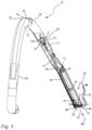
- the implement 1 includes a grip tube insert 17.
- the grip tube insert 17 is preferably formed from a metal alloy.
- the handle tube insert 17 is used to attach the front handle 6 to the housing 2 of the implement 1.
- the handle tube insert 17 is at one end 20 of the front handle 6 in Interior 10 of the front handle 6 arranged.
- the grip tube insert 17 comprises a plurality of openings 41, three openings 41 in the preferred exemplary embodiment. Of course, it can be expedient to provide fewer or more than three openings in the preferred exemplary embodiment.
- the front handle 6 also includes openings 42 on its side section 33, which are formed coaxially with the openings 41 of the handle tube insert 17 when the handle tube insert 17 is in the fastened state.
- the openings 41 of the handle tube insert 17 and the openings 42 of the front handle 6 are designed in such a way that the front handle 6 with the handle tube insert 17 can be fastened to receiving openings of the housing 2 via a plurality of screws 44 protruding through the openings 41, 42.
- the grip tube insert 17 stabilizes the front handle 6, as a result of which the front handle 6 can be screwed to the housing 2 with a high tightening torque of the screws 44 without being deformed in the process.
- the grip tube insert 17 includes a cable duct 18.
- the cable duct 18 serves to guide the connecting cables 15, 15'.
- the cable duct 18 is designed as a groove on the outside of the handle tube insert 17 . It can also be expedient to form the cable duct 18 as a bore through the grip tube insert 17 .
- the cable duct 18 extends from an upper end 45 of the handle tube insert 17 to a lower end 46 of the handle tube insert 17.
- the handle tube insert 17 extends in its longitudinal direction 47 from the upper end 45 to the lower end 46.
- the longitudinal direction 47 of the handle tube insert 17 corresponds to the insertion direction 48 of the grip tube insert 17 in the front handle 6.
- a cable fixation 19 for clamping the connecting cables 15, 15' is formed on the grip tube insert 17.
- the cable fixation 19 is formed from a further cable duct 49 which connects to the cable duct 18 .
- the other cable duct 49 is formed obliquely to the cable duct 18 of the grip tube insert 17 .
- the longitudinal axes of the cable duct 18 of the grip tube insert 17 and of the further cable duct 49 of the grip tube insert 17 enclose an angle ⁇ , with the angle ⁇ being in a range between 70° and 140°, in particular in a range between 90° and 130°.
- a plurality of lugs 50 are formed on the further cable duct 49 .
- the lugs 50 are arranged alternately on opposite sides of the further cable duct 49 and protrude at least partially into the further cable duct 49.
- the connecting cables 15, 15' are held clamped in the further cable duct 49 by the lugs 50 arranged alternately.
- the hand-held power tool 1 preferably comprises at least one contact point for connecting the second electrical functional element 14 to the at least one connecting cable 15, 15'.
- the contact point is preferably formed in the vicinity of the opening 8 .
- the contact point is preferably provided on the connecting portion 35 of the front handle 6.
- the contact point is preferably provided on a side of the connecting section 35 of the front handle 6 which faces the housing 2 .
- the contact point is preferably designed as a soldered connection in order to keep an exposed cable length of the at least one connecting cable 15, 15' as short as possible.
- the exposed cable length is the section of the at least one connecting cable 15, 15 which is arranged on the outside 12 of the front handle 6.
- the at least one connecting cable 15, 15' has a concealed cable length which corresponds to the length of the connecting cable 15, 15' from the opening 8 to the end 20 of the front handle 6.
- the exposed cable length corresponds to at most 20%, in particular at most 15%, preferably at most 10% of the covered cable length of the at least one connecting cable.
- the exposed cable length corresponds to at most 20%, in particular at most 15%, preferably at most 10% of a distance a between the opening 8 and the end 20 of the front handle 6.
- the exposed cable length of the at least one connecting cable 15, 15' is less than 40mm, in particular less than 30mm.
- the exposed cable length is preferably about 25 mm.
- the concealed cable length of the at least one connecting cable 15, 15' preferably lies in a range between 175 mm to 325 mm, in particular between 205 mm to 275 mm.
- the concealed cable length of the at least one connecting cable 15, 15' is approximately 235 mm.
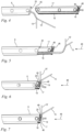
- FIG. 4 to 7 the individual steps for mounting the grip tube insert 17 on the front handle 6 are shown.
- the end 20 of the front handle 6 is shown, with the connection cables 15, 15' protruding from the end 20 of the front handle 6.
- the grip tube insert 17 is located outside of the front handle 6.
- the connecting cables 15, 15' are to be inserted into the cable duct 18.
- the grip tube insert 17 is to be pushed into the interior 10 of the front handle 6 in the insertion direction 48, as shown in FIG figure 5 shown.
- the connecting cables 15, 15' are to be guided through the cable duct 18 of the grip tube insert 17.
- the connecting cables 15, 15' can be clamped in the further cable duct 49 via the lugs 50 ( 6 ).
- the grip tube insert 17 can then be pushed into the front handle 6 as far as it will go.
Landscapes
- Life Sciences & Earth Sciences (AREA)
- Biodiversity & Conservation Biology (AREA)
- Ecology (AREA)
- Forests & Forestry (AREA)
- Environmental Sciences (AREA)
- Engineering & Computer Science (AREA)
- Mechanical Engineering (AREA)
- Harvester Elements (AREA)
- Dental Tools And Instruments Or Auxiliary Dental Instruments (AREA)
Abstract
Description
- Die Erfindung betrifft ein handgetragenes Arbeitsgerät gemäß dem Oberbegriff des Anspruchs 1.
- Es sind handgetragene Arbeitsgeräte, beispielsweise eine Motorkettensäge, eine Heckenschere, oder ähnliche bekannt, deren üblicher Einsatz im Freien erfolgt. Unter einem handgetragenen Arbeitsgerät ist ein Arbeitsgerät zu verstehen, dessen bestimmungsgemäßer Einsatz insbesondere getragen durch den Bediener erfolgt. Bei besonders niedrigen Temperaturen sind die Handgriffe des Arbeitsgerätes kalt. Um die Handgriffe zu erwärmen, ist der Einsatz von Griffheizungen bekannt. Eine Griffheizung kann als elektrische Griffheizung ausgebildet sein, die mit einem Generator oder einer Batterie des Arbeitsgerätes verbunden ist.
- Es wurde festgestellt, dass die Funktion derartiger Griffheizungen nach einer gewissen Betriebsdauer der Arbeitsgeräte oftmals nicht mehr gegeben war.
- Der Erfindung liegt somit die Aufgabe zugrunde, ein handgetragenes Arbeitsgerät anzugeben, dass einen zuverlässigen Betrieb von einem auf einem Handgriff des Arbeitsgerätes angeordneten elektrischen Funktionselementes ermöglicht.
- Diese Aufgabe wird durch ein handgetragenes Arbeitsgerät gemäß den Merkmalen nach Anspruch 1 gelöst.
- Der Erfindung liegt die Erkenntnis zugrunde, dass der im Betrieb des Arbeitsgerätes auftretende Defekt des oben beschriebenen am Handgriff angeordneten Funktionselementes, wie beispielsweise eine Griffheizung, auf einen Kabelbruch des Verbindungskabels zurückzuführen ist. Das Verbindungskabel zwischen der Griffheizung und der Stromquelle für die Griffheizung verläuft an der Außenseite des Griffrohres und ist durch einen Griffüberzug bedeckt. Im Einsatz des Arbeitsgerätes können unter anderem Äste von Gebüschen, Sträuchern oder Bäumen an dem Handgriff entlang streifen und dabei den Griffüberzug sowie das Verbindungskabel beschädigen.
- Das erfindungsgemäße handgetragene Arbeitsgerät umfasst ein Gehäuse, wobei das Gehäuse eine Oberseite, eine Unterseite, eine erste Längsseite und eine zweite Längsseite aufweist, wobei die Oberseite und die Unterseite über die erste Längsseite und über die zweite Längsseite miteinander verbunden sind. Das handgetragene Arbeitsgerät umfasst einen in dem Gehäuse angeordneten Antriebsmotor, wobei der Antriebsmotor ein am vorderen Ende des Gehäuses angeordnetes Werkzeug antreibt. Das handgetragene Arbeitsgerät umfasst einen vorderen Handgriff und einen hinteren Handgriff, wobei der vordere Handgriff als ein Bügelgriff ausgebildet ist und einen sich entlang der Oberseite des Gehäuses erstreckenden Querabschnitt und einen entlang einer der beiden Längsseiten des Gehäuses erstreckenden Seitenabschnitt aufweist. Der vordere Handgriff weist eine Wand und einen von der Wand umschlossenen Innenraum auf, wobei die Wand des vorderen Handgriffes eine dem Innenraum zugewandte Innenseite und eine dem Innenraum abgewandte Außenseite umfasst. Im Gehäuse ist ein erstes elektrisches Funktionselement angeordnet. Auf der Außenseite des vorderen Handgriffes ist mindestens ein zweites elektrisches Funktionselement angeordnet. Das erste elektrische Funktionselement ist mit dem zweiten Funktionselement über mindestens ein Verbindungskabel verbunden. Das mindestens eine Verbindungskabel ist zumindest teilweise im Innenraum des vorderen Handgriffes im Bereich des Seitenabschnitts des vorderen Handgriffs angeordnet.
- Das Verbindungskabel liegt zumindest teilweise im Innenraum des Seitenabschnittes des vorderen Handgriffes und ist somit durch den vorderen Handgriff geschützt. Äste oder ähnliches können somit den vorderen Handgriff des Arbeitsgerätes am Seitenabschnitt tangieren ohne dabei das Verbindungskabel zu beschädigen. Ein zuverlässiger Betrieb des zweiten elektrischen Funktionselementes ist somit gewährleistet.
- Das zweite elektrische Funktionselement ist bevorzugt als Heizfolie ausgebildet. In einer alternativen Ausgestaltung kann das zweite elektrische Funktionselement auch als Sensor ausgebildet sein.
- Das erste elektrische Funktionselement ist bevorzugt eine Energiequelle zur Versorgung des zweiten Funktionselementes mit elektrischem Strom. Die Energiequelle ist bevorzugt ein Generator. Alternativ kann die Energiequelle auch eine Batterie sein. Das erste elektrische Funktionselement kann alternativ auch eine Steuereinheit zur Verarbeitung von Datensignalen sein. Die Steuereinheit ist über eine Energiequelle mit elektrischem Strom versorgt.
- Es ist vorteilhaft vorgesehen, dass an der Wand des vorderen Handgriffes, insbesondere benachbart, zum zweiten elektrischen Funktionselement eine Öffnung vorgesehen ist, wobei sich die Öffnung von der Außenseite der Wand zur Innenseite der Wand erstreckt, wobei das mindestens eine Verbindungskabel von der Außenseite der Wand durch die Öffnung in den Innenraum des Handgriffes verläuft. Die Öffnung ist vorzugsweise mit einer Tülle als Kantenschutz versehen. Die Tülle ist vorzugsweise aus einem Elastomer gebildet. Dadurch kann ein Aufscheuern des Verbindungskabels an der Öffnung vermieden.
- Es ist bevorzugt vorgesehen, dass der vordere Handgriff einen in etwa horizontal verlaufenden Halteabschnitt aufweist, wobei die Öffnung der Wand außerhalb des Halteabschnittes vorgesehen ist. Der horizontal verlaufende Halteabschnitt ist zum Halten des Arbeitsgerätes im bestimmungsgemäßen Betrieb des Arbeitsgerätes vorgesehen ist.
- Demnach ist der horizontal verlaufende Halteabschnitt der Bereich des vorderen Handgriffes, den der Bediener am häufigsten umgreift. Wäre die Öffnung also an dem horizontal verlaufenden Halteabschnitt vorgesehen, würde diese der Bediener spüren. Der Bediener könnte die Öffnung aus ergonomischer Sicht als unangenehm wahrnehmen. Um diesen Umstand zu vermeiden, ist die Öffnung außerhalb des horizontal verlaufenden Abschnittes vorgesehen.
- Es ist vorzugsweise vorgesehen, dass der Querabschnitt und der Seitenabschnitt des vorderen Handgriffes über einen gekrümmten Verbindungsabschnitt miteinander verbunden sind, wobei die Öffnung im Seitenabschnitt benachbart zum Verbindungsabschnitt vorgesehen ist. Eine Öffnung im horizontal verlaufenden Abschnitt des vorderen Handgriffes ist aus bereits oben beschriebenen Gründen zu vermeiden. Ferner sollte die Öffnung auch nicht in dem gekrümmten Verbindungsabschnitt ausgebildet sein. Eine Öffnung in der Krümmung wäre aus Gründen der hohen Spannungsverhältnisse und der damit verbunden Schwächung der Festigkeit des vorderen Handgriffes nachteilig. Ferner sollte das Verbindungskabel zu möglichst großen Teilen durch den vorderen Handgriff geschützt sein. Daher ist die Öffnung im Seitenabschnitt vorzugsweise unmittelbar angrenzend an dem Krümmungsabschnitt des vorderen Handgriffes vorzusehen. Der Handgriff ist bevorzugt aus Aluminium oder Kunststoff gebildet.
- Es ist insbesondere vorgesehen, dass das Arbeitsgerät eine Griffrohreinlage zur Befestigung des vorderen Handgriffes am Gehäuse des Arbeitsgerätes umfasst, wobei die Griffrohreinlage im Innenraum des Handgriffes an einem Ende des vorderen Handgriffes angeordnet ist. Die Griffrohreinlage weist einen Kabelkanal zur Führung des mindestens einen Verbindungskabels auf. Bei der Montage des Arbeitsgerätes kann die Griffrohreinlage in den vorderen Handgriff eingeführt werden, wobei das Verbindungskabel dabei in dem Kabelkanal geführt ist. Somit kann vermieden werden, dass sich das Verbindungskabel zwischen der Griffrohreinlage und dem Handgriff verklemmt. Die Griffrohreinlage weist eine Kabelfixierung zur Klemmung des mindestens einen Verbindungskabels auf. Ist also die Griffrohreinlage beinahe vollständig in den vorderen Handgriff eingeführt, kann das Verbindungskabel in der Kabelfixierung fixiert werden. Somit kann gezielt die Länge des Abschnittes des Verbindungskabels eingestellt werden, der in dem vorderen Handgriff vorgesehen ist. Zum anderen ist die Anbindungsstelle des Verbindungskabels an dem zweiten Funktionselement durch die Klemmung an der Griffrohreinlage entlastet. Insbesondere bei der Montage des Arbeitsgerätes kann es zu einer Zugbelastung des Verbindungskabels kommen. Durch die Klemmung des Verbindungskabels wird die Zugbelastung bereits an der Klemmstelle des Verbindungskabels abgefangen. Die Anbindung des Verbindungskabels und des zweiten elektrischen Funktionselementes bleibt unbeschädigt.
- Es ist vorteilhaft vorgesehen, dass das Verbindungskabel von der Außenseite der Wand des vorderen Handgriffes über den Innenraum des vorderen Handgriffes durch den Verbindungskanal der Griffrohreinlage bis zu dem einen Ende des vorderen Handgriffes verläuft. Somit liegt das Verbindungskabel zu großen Teilen vor Außenbelastungen im vorderen Handgriff geschützt.
- Weitere Merkmale der Erfindung ergeben sich aus der Beschreibung und der Zeichnung. Nachstehend ist ein im Einzelnen beschriebenes Ausführungsbeispiel wiedergegeben. Es zeigen:
- Fig. 1
- in einer schematischen, ausschnittsweisen, perspektivischen Darstellung eine Motorkettensäge,
- Fig. 2
- in einer perspektivischen Darstellung einen vorderen Handgriff und ein elektrisches Funktionselement der Motorkettensäge nach
Fig. 1 , - Fig. 3
- in einer Seitenansicht den vorderen Handgriff und das elektrische Funktionselement der Motorkettensäge nach
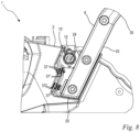
Fig. 1 , - Figuren 4 bis 7
- in Seitenansicht einzelne Montageschritte bezüglich der Befestigung einer Griffrohreinlage mit Kabelkanal und Kabelfixierung in dem vorderen Handgriff der Motorkettensäge nach
Fig. 1 und - Fig. 8
- in einer schematischen, ausschnittsweisen Seitendarstellung die Motorkettensäge nach
Fig. 1 . - In
Fig. 1 ist ein Ausführungsbeispiel eines handgetragenen Arbeitsgerätes 1 gezeigt, welches als eine "rear-handle" Motorkettensäge ausgebildet ist. In einer alternativen Ausführung kann das Arbeitsgeräte 1 auch eine "top-handle" Motorkettensäge sein. Das Arbeitsgerät kann auch als eine Heckenschere, Trennschleifer, Blasgerät, Freischneider oder dgl. ausgebildet sein. Das Arbeitsgerät 1 umfasst ein Gehäuse 2 und einen im Gehäuse 2 angeordneten Antriebsmotor 3. Der Antriebsmotor 3 ist im bevorzugten Ausführungsbeispiel als Verbrennungsmotor ausgebildet. In einer alternativen Ausgestaltung des Arbeitsgerätes 1 kann es zweckmäßig sein, den Antriebsmotor 3 auch als Elektromotor auszubilden, der wiederum über einen Akku oder über ein Anschlusskabel an einem Stromnetz mit Energie versorgt sein kann. - Wie in
Fig. 1 gezeigt, weist das Gehäuse 2 eine Oberseite 26, eine Unterseite 27, eine erste Längsseite 28 und eine zweite Längsseite 29 auf. Die Oberseite 26 und die Unterseite 27 sind über die beiden Längsseiten 28, 29 miteinander verbunden. Zudem umfasst das Arbeitsgerät 1 einen vorderen Handgriff 6 und einen hinteren Handgriff 36. Die Handgriffe 6, 36 dienen zum Halten und Führen des Arbeitsgerätes 1. Der hintere Handgriff ist an einem hinteren Ende 31 des Gehäuses 2 ausgebildet. An der dem hinteren Handgriff 36 gegenüberliegenden Seite des Gehäuses 2, also einem vorderen Ende 30 des Gehäuses 2, ragt eine Führungsschiene 4 nach vorn. An der Führungsschiene 4 ist eine Sägekette umlaufend angeordnet, die von dem Antriebsmotor 3 angetrieben ist. Die Sägekette bildet das Werkzeug 5 des Arbeitsgerätes 1. - Der Antriebsmotor 3 treibt über eine nicht näher dargestellte Antriebswelle ein Antriebskettenrad an. Das Antriebskettenrad dient zum Antrieb der Sägekette, die im Betrieb über das Antriebskettenrad geführt ist. Ferner umfasst das Arbeitsgerät 1 eine Spannvorrichtung 21, über die die Führungsschiene 4 in Richtung ihrer Längsachse 22 nach vorne weg vom Antriebskettenrad verschiebbar ist. Die Längsachse 22 verläuft in einem auf einem ebenen horizontalen Boden 51 abgestellten Zustand des Arbeitsgerätes 1 mittig durch die Führungsschiene 4 in etwa parallel zum horizontalen Boden 51. Der Begriff "in etwa" ist derart zu verstehen, dass die Längsachse 22 der Führungsschiene 4 mit dem Boden 51 einen Winkel von höchstens 15° einschließt. Die Führungsschiene 4 besitzt eine Längsebene 23, welche in einem auf einem ebenen horizontalen Boden 51 abgestellten Zustand des Arbeitsgerätes 1 die Längsachse 22 enthält und senkrecht zum Boden 51 steht.
- Im Ausführungsbeispiel ist der vordere Handgriff 6 als ein Bügelgriff ausgebildet. Der vordere Handgriff 6 ist aus einem Griffrohr gebildet. Der vordere Handgriff 6 ist bevorzugt aus Aluminium oder Kunststoff gebildet ist. Der vordere Handgriff 6 weist einen sich entlang der Oberseite 26 des Gehäuses 2 erstreckenden Querabschnitt 32, einen sich entlang der ersten Längsseite 28 erstreckenden Seitenabschnitt 33 und einen sich entlang der zweiten Längsseite 29 erstreckenden, weiteren Seitenabschnitt 34 auf. An den jeweiligen Enden des vorderen Handgriffes 6 ist dieser an dem Gehäuse 2 befestigt. Das Ende der ersten Längsseite 28 des vorderen Handgriffes 6 ist an dem Seitenabschnitt 33 des Gehäuses 2 befestigt. Das andere Ende des vorderen Handgriffes 6 ist an der Unterseite 27 des Gehäuses 2 befestigt.
- Wie in
Fig. 1 gezeigt, ist im Gehäuse 2 ein lediglich schematisch dargestelltes, elektrisches Funktionselement 13 angeordnet. Das elektrische Funktionselement 13 ist im Ausführungsbeispiel als eine Steuereinheit ausgebildet. Die Steuereinheit ist zur Verarbeitung von Informationen und zur Steuerung verschiedener Komponenten des Arbeitsgerätes 1, wie beispielsweise den Antriebsmotor 3, ausgebildet. Im Ausführungsbeispiel wird die Steuereinheit über einen am Antriebsmotor 3 vorgesehenen Generator mit elektrischem Strom versorgt. - Wie in den
Figuren 1 und2 gezeigt, ist am vorderen Handgriff 6 ein zweites elektrisches Funktionselement 14 angeordnet. Das zweite elektrische Funktionselement 14 ist als Heizfolie ausgebildet. Die Heizfolie dient zur Aufheizung des vorderen Handgriffes 6 und bildet somit eine Griffheizung. In einer alternativen Ausgestaltung des Arbeitsgerätes kann das zweite elektrische Funktionselement 14 auch als ein Sensor ausgebildet sein. Der Sensor ist vorzugsweise dazu ausgebildet, zu erkennen, ob der vordere Handgriff 6 vom Bediener umfasst ist. Der Sensor ist bevorzugt ein kapazitiver Sensor. In einer alternativen Ausgestaltung des Arbeitsgerätes 1 kann es auch zweckmäßig sein, am vorderen Handgriff 6 mehrere elektrische Funktionselemente vorzusehen. Demnach kann das zweite elektrische Funktionselement 14 als Heizfolie und ein drittes elektrisches Funktionselement als Sensor ausgebildet sein. Der vordere Handgriff 6 umfasst zudem vorzugsweise einen Überzug 38. Der Überzug 38 ummantelt insbesondere einen Halteabschnitt 16 des vorderen Handgriffes 6. Der Überzug 38 ist aus einem Kunststoff, insbesondere aus einem Elastomer, gebildet, und dient zur Fixierung des zweiten, elektrischen Funktionselementes 14 auf dem vorderen Handgriff 6. Ferner bietet der Überzug 38 dem Bediener einen besseren, komfortableren Halt am vorderen Handgriff 6. - Wie in den
Figuren 1 und2 gezeigt, umfasst das Arbeitsgerät 1 mindestens ein Verbindungskabel 15, wobei das Verbindungskabel 15 das erste elektrische Funktionselement 13 und das zweite elektrische Funktionselement 14 miteinander verbindet. Der Begriff "Verbindungskabel" ist nicht auf ein Einzelkabel zu beschränken, sondern umfasst auch mehrere Kabel. Vorzugsweise sind die Kabel in Reihe miteinander verbundene Kabel. Wie inFig. 2 gezeigt, umfasst das Arbeitsgerät 1 neben dem mindestens einem Verbindungskabel 15 ein weiteres Verbindungkabel 15'. Im Ausführungsbeispiel ist das mindestens eine Verbindungskabel 15 ein erster Leiter, das zweite Verbindungskabel 15' ein zweiter Leiter. Im Ausführungsbeispiel verläuft das mindestens eine Verbindungkabel 15 von dem als Heizfolie ausgebildeten elektrischen zweiten Funktionselement 14 zum ersten elektrischen Funktionselement 13, der Steuereinheit. - Im Ausführungsbeispiel ist zwischen dem ersten elektrischen Funktionselement 13 und dem zweiten Funktionselement 14 ein Schalter 24 (siehe auch
Fig. 8 ) zwischengeschaltet. Das zweite Verbindungskabel 15' ist unmittelbar mit dem ersten elektrischen Funktionselement 13 verbunden. Ist der Schalter 24 aktiviert, ist der Stromkreis geschlossen und das zweite elektrische Funktionselement 14 kann mit Strom versorgt werden. Ist der Schalter 24 deaktiviert, ist die Stromzufuhr unterbunden. - In einer alternativen Ausgestaltung des Arbeitsgerätes 1 kann es zweckmäßig sein, als erstes elektrisches Funktionselement 13 den Generator vorzusehen. Der Generator ist vorzugsweise ein Wechselspannungsgenerator. Demnach wäre das zweite elektrische Funktionselement 14 über das Verbindungskabel 15 mit dem Generator verbunden. Bevorzugt ist zwischen dem Generator und dem zweiten elektrischen Funktionselement 13 ein Gleichrichter vorgesehen.
- Wie in den
Figuren 2 und3 gezeigt, ist das elektrische zweite Funktionselement 14 auf einer Außenseite 12 des vorderen Handgriffes 6 angeordnet. Die Verbindungskabel 15, 15' verlaufen ausgehend von dem zweiten Funktionselement 14 über eine Öffnung 8 am vorderen Handgriff 6 in einen Innenraum 10 des vorderen Handgriffes 6. Der vordere Handgriff 6 weist eine Wand 7 auf, wobei die Wand 7 den Innenraum 10 des vorderen Handgriffes 6 umschließt. Demnach umfasst die Wand 7 des vorderen Handgriffes 6 eine dem Innenraum 10 zugewandte Innenseite 11 und die dem Innenraum 10 abgewandte Außenseite 12. Die Öffnung 8 erstreckt sich von der Außenseite 12 der Wand 7 zur Innenseite 11 der Wand 7. - Wie in den
Figuren 2 und3 gezeigt, ist das zweite elektrische Funktionselement 14 auf einem in etwa horizontal verlaufenden Halteabschnitt 16 des vorderen Handgriffes 6 angeordnet. Der Halteabschnitt 16 ist an dem Querabschnitt 32 des vorderen Handgriffes 6 ausgebildet. Der Halteabschnitt 16 ist der Bereich des vorderen Handgriffes 6, an welchem der Bediener das Arbeitsgerät 1 in einer für das Arbeitsgerät vorgesehenen Arbeitshaltung bevorzugt greift. Ferner erstreckt sich das zweite elektrische Funktionselement 14 über den Querabschnitt 32 bis hin zu dem weiteren Längsabschnitt 34 des vorderen Handgriffes 6. In einem alternativen Ausführungsbeispiel kann es zweckmäßig sein, dass sich das zweite elektrische Funktionselement 14 von dem weiteren Längsabschnitt 34 über den Querabschnitt 32 bis hin zu dem Längsabschnitt 33 erstreckt. - Wie in den
Figuren 2 und3 gezeigt, ist die Öffnung 8 an dem Seitenabschnitt 33 des vorderen Handgriffes 6 ausgebildet. Die Öffnung 8 ist an einer dem Gehäuse 2 zugewandten Seite des vorderen Handgriffes 6 ausgebildet. Damit liegt die Öffnung 8 und die an der Öffnung 8 verlaufenden Verbindungskabel 15, 15' geschützt vor Ästen, Gestrüpp oder anderen Gegenständen, die in Betrieb des Arbeitsgerätes 1 mit dem vorderen Handgriff 6 in Kontakt kommen können. Wie insbesondere inFig. 2 gezeigt, ist die Öffnung 8 außerhalb des Halteabschnittes 16 angeordnet. Somit stört die Öffnung 8 den Bediener beim Umgreifen des Halteabschnittes 16 aus ergonomischer Sicht nicht. Die Öffnung 8 ist im bevorzugten Ausführungsbeispiel an dem Seitenabschnitt 33 unmittelbar benachbart zu einem Verbindungsabschnitt 35 des vorderen Handgriffes 6 angeordnet. Der Verbindungsabschnitt 35 ist gekrümmt ausgebildet und verbindet den Querabschnitt 32 und den Seitenabschnitt 33 des vorderen Handgriffes 6. Die Öffnung 8 liegt in anderen Worten unmittelbar unterhalb des Verbindungsabschnittes 35. Die Öffnung 8 ist bevorzugt aus Gründen der Festigkeit und der einfacheren Fertigung des vorderen Handgriffes 8 außerhalb des Verbindungsabschnittes 35 vorzusehen. Natürlich kann es in einer alternativen Ausgestaltung des Arbeitsgerätes 1 auch zweckmäßig sein, die Öffnung 8 im Verbindungsabschnitt 35 vorzusehen. Ferner ist die Öffnung 8 möglichst "oben" an dem Seitenabschnitt 33, also benachbart zum Verbindungsabschnitt 35 festzulegen, um die Verbindungskabel 15, 15' über einen möglichst weiten Bereich in dem vorderen Handgriff 6 geschützt führen zu können. - Die nicht näher dargestellten Anschlüsse des zweiten elektrischen Funktionselementes 14 für die Verbindungskabel 15, 15' sind im bevorzugten Ausführungsbeispiel an der Außenseite 12 im Verbindungsabschnitt 35 angeordnet sind. Es kann auch zweckmäßig sein, dass die Anschlüsse des zweiten elektrischen Funktionselementes 14 für die Verbindungskabel 15, 15' an der Außenseite 12 im Querabschnitt 32 des vorderen Handgriffes 6 angeordnet sind. Die Verbindungskabel 15, 15' verlaufen an der Außenseite 12 des vorderen Handgriffes 6 ausgehend vom Verbindungsabschnitt 35 über die Öffnung 8 in den Innenraum 10 des vorderen Handgriffes 6. An der Öffnung 8 ist eine Tülle 9 vorgesehen, wobei die Tülle 9 einen Kantenschutz an der Öffnung 8 bildet. Dadurch werden Beschädigungen der Verbindungskabel 15, 15' vermieden. Die Verbindungskabel 15, 15' verlaufen von dem Innenraum 10 an der Öffnung 8 bis zu einem Ende 20 des Handgriffes 6.
- Wie in
Fig. 8 gezeigt, verlassen die Verbindungskabel 15, 15' an dem Ende 20 des Handgriffes 6 den Innenraum 10 des vorderen Handgriffes 6. Die Verbindungskabel 15, 15' verlaufen ausgehend von dem Ende 20 des vorderen Handgriffes 6 an dem Gehäuse 2 des Arbeitsgerätes entlang zum ersten elektrischen Funktionselement 13. Wie bereits oben beschrieben, ist das mindestens eine Verbindungskabel 15 über einen Schalter 24 mit dem ersten elektrischen Funktionselement 13 verbunden. Die Verbindungskabel 15, 15' sind an dem Gehäuse 2 des Arbeitsgerätes 1 über mehrere Klemmen 37, 37', 37", 37'" gehalten. - Wie in
Fig. 3 gezeigt, umfasst das Arbeitsgerät 1 eine Griffrohreinlage 17. Die Griffrohreinlage 17 ist vorzugsweise aus einer Metalllegierung gebildet. Die Griffrohreinlage 17 dient zur Befestigung des vorderen Handgriffes 6 am Gehäuse 2 des Arbeitsgerätes 1. Die Griffrohreinlage 17 ist an dem einen Ende 20 des vorderen Handgriffes 6 im Innenraum 10 des vorderen Handgriffes 6 angeordnet. Die Griffrohreinlage 17 umfasst mehrere Öffnungen 41, im bevorzugten Ausführungsbeispiel drei Öffnungen 41. Selbstverständlich kann es zweckmäßig sein, im bevorzugten Ausführungsbeispiel weniger oder mehr als drei Öffnungen vorzusehen. Der vordere Handgriff 6 umfasst an seinem Seitenabschnitt 33 ebenfalls Öffnungen 42, die im befestigten Zustand der Griffrohreinlage 17 koaxial zu den Öffnungen 41 der Griffrohreinlage 17 ausgebildet sind. Die Öffnungen 41 der Griffrohreinlage 17 und die Öffnungen 42 des vorderen Handgriffes 6 sind derart ausgebildet, dass der vordere Handgriff 6 mit der Griffrohreinlage 17 über mehrere die Öffnungen 41, 42 durchragende Schrauben 44 an Aufnahmeöffnungen des Gehäuses 2 befestigbar ist. Die Griffrohreinlage 17 stabilisiert den vorderen Handgriff 6, wodurch der vordere Handgriff 6 mit einem hohen Anzugsmoment der Schrauben 44 an dem Gehäuse 2 festgeschraubt werden kann, ohne sich dabei zu verformen. - Wie in
Fig. 3 gezeigt, umfasst die Griffrohreinlage 17 einen Kabelkanal 18. Der Kabelkanal 18 dient zur Führung der Verbindungskabel 15, 15'. Der Kabelkanal 18 ist im Ausführungsbeispiel als eine Nut an der Außenseite der Griffrohreinalge 17 ausgebildet. Es kann auch zweckmäßig sein, den Kabelkanal 18 als eine Bohrung durch die Griffrohreinlage 17 auszubilden. Der Kabelkanal 18 erstreckt sich von einem oberen Ende 45 der Griffrohreinlage 17 bis zu einem unteren Ende 46 der Griffrohreinlage 17. Die Griffrohreinlage 17 erstreckt sich in ihrer Längsrichtung 47 von dem oberen Ende 45 bis zu dem unteren Ende 46. Die Längsrichtung 47 der Griffrohreinlage 17 entspricht der Einsteckrichtung 48 der Griffrohreinalge 17 in den vorderen Handgriff 6. Am unteren Ende 46 der Griffrohreinlage 17 ist an der Griffrohreinlage 17 eine Kabelfixierung 19 zur Klemmung der Verbindungskabel 15, 15'ausgebildet. Die Kabelfixierung 19 ist aus einem weiteren Kabelkanal 49 gebildet, der an dem Kabelkanal 18 anschließt. Der weitere Kabelkanal 49 ist schräg zu dem Kabelkanal 18 der Griffrohreinlage 17 ausgebildet. In einer Blickrichtung in Achsrichtung der Schrauben 43 auf die an dem vorderen Handgriff 6 befestigte Griffrohreinlage 17 schließen die Längsachsen des Kabelkanals 18 der Griffrohreinlage 17 und des weiteren Kabelkanals 49 der Griffrohreinlage 17 einen Winkel α ein, wobei de Winkel α in einem Bereich zwischen 70° und 140°, insbesondere in einem Bereich zwischen 90° und 130° liegt. An dem weiteren Kabelkanal 49 sind mehrere Nasen 50 ausgebildet. Die Nasen 50 sind wechselseitig auf gegenüberliegenden Seiten des weiteren Kabelkanals 49 angeordnet und ragen zumindest teilweise in den weiteren Kabelkanal 49. Durch die wechselseitig angeordneten Nasen 50 sind die Verbindungskabel 15, 15' in dem weiteren Kabelkanal 49 geklemmt gehalten. - Das handgeführte Arbeitsgerät 1 umfasst vorzugsweise mindestens eine Kontaktstelle zur Verbindung des zweiten elektrischen Funktionselementes 14 mit dem mindestens einen Verbindungskabel 15, 15'. Die Kontaktstelle ist vorzugsweise in der Nähe der Öffnung 8 ausgebildet. Die Kontaktstelle ist vorzugsweise an dem Verbindungsabschnitt 35 des vorderen Handgriffes 6 vorgesehen. Die Kontaktstelle ist vorzugsweise an einer dem Gehäuse 2 zugewandten Seite des Verbindungsabschnittes 35 des vorderen Handgriffes 6 vorgesehen. Bevorzugt ist die Kontaktstelle als Lötverbindung ausgebildet, um eine freiliegende Kabellänge des mindestens einen Verbindungskabel 15, 15' möglichst kurz zu halten. Die freiliegende Kabellänge ist der Abschnitt des mindestens einen Verbindungskabels 15, 15, der an der Außenseite 12 des vorderen Handgriffes 6 angeordnet ist. Ferner weist das mindestens eine Verbindungskabel 15, 15' eine verdeckte Kabellänge auf, die der Länge des Verbindungskabels 15, 15' von der Öffnung 8 bis zu dem Ende 20 des vorderen Handgriffes 6 entspricht. Die freiliegende Kabellänge entspricht höchstens 20%, insbesondere höchstens 15%, vorzugsweise höchstens 10% der verdeckten Kabellänge des mindestens einen Verbindungskabels. Die freiliegende Kabellänge entspricht höchstens 20%, insbesondere höchstens 15%, vorzugsweise höchstens 10% eines Abstandes a zwischen der Öffnung 8 und des Endes 20 des vorderen Handgriffes 6. Die freiliegende Kabellänge des mindestens einen Verbindungskabels 15, 15' beträgt weniger als 40mm, insbesondere weniger als 30 mm. Die freiliegende Kabellänge beträgt bevorzugt in etwa 25 mm. Die verdeckte Kabellänge des mindestens einen Verbindungskabels 15, 15' liegt in einem Bereich zwischen vorzugsweise 175 mm bis 325 mm, insbesondere zwischen 205 mm bis 275 mm. Die verdeckte Kabellänge des mindestens einen Verbindungskabels 15, 15' beträgt in etwa 235 mm.
- In den
Figuren 4 bis 7 sind die einzelnen Schritte zur Montage der Griffrohreinlage 17 an dem vorderen Handgriff 6 gezeigt. InFig. 4 ist das Ende 20 des vorderen Handgriffs 6 gezeigt, wobei die Verbindungskabel 15, 15' aus dem Ende 20 des vorderen Handgriffes 6 ragen. Die Griffrohreinlage 17 befindet sich außerhalb des vorderen Handgriffes 6. Die Verbindungskabel 15, 15' sind in den Kabelkanal 18 einzulegen. Anschließend ist die Griffrohreinlage 17 in Einsteckrichtung 48 in den Innenraum 10 des vorderen Handgriffes 6 einzuschieben, wie inFig. 5 gezeigt. Die Verbindungskabel 15, 15' sind dabei durch den Kabelkanal 18 der Griffrohreinlage 17 zu führen. Noch bevor die Griffrohreinlage 17 bis auf Anschlag in den vorderen Handgriff 6 eingeschoben ist, können die Verbindungskabel 15, 15' in den weiteren Kabelkanal 49 über die Nasen 50 eingeklemmt werden (Fig. 6 ). Anschließend kann die Griffrohreinlage 17 auf Anschlag in den vorderen Handgriff 6 eingeschoben werden.
Claims (14)
- Handgetragenes Arbeitsgerät- mit einem Gehäuse (2), wobei das Gehäuse (2) eine Oberseite (26), eine Unterseite (27), eine erste Längsseite (28) und eine zweite Längsseite (29) aufweist, wobei die Oberseite (26) und die Unterseite (27) über die beiden Längsseiten (28, 29) miteinander verbunden sind,- mit einem in dem Gehäuse (2) angeordneten Antriebsmotor (3), wobei der Antriebsmotor (3) ein am vorderen Ende (30) des Gehäuses (2) angeordnetes Werkzeug (5) antreibt,- mit einem vorderen Handgriff (6) und einem hinteren Handgriff (36),wobei der vordere Handgriff (6) als ein Bügelgriff ausgebildet ist und einen sich entlang der Oberseite (26) des Gehäuses (2) erstreckenden Querabschnitt (32) und einen entlang einer der beiden Längsseiten (28, 29) des Gehäuses (2) erstreckenden Seitenabschnitt (33) aufweist,- wobei der vordere Handgriff (6) eine Wand (7) und einen von der Wand (7) umschlossenen Innenraum (10) aufweist, wobei die Wand (7) des vorderen Handgriffes (6) eine dem Innenraum (10) zugewandte Innenseite (11) und eine dem Innenraum (10) abgewandte Außenseite (12) umfasst,- wobei im Gehäuse (2) ein erstes elektrisches Funktionselement (13) angeordnet ist, und- wobei auf der Außenseite (12) des vorderen Handgriffes (6) mindestens ein zweites elektrisches Funktionselement (14) angeordnet ist,- wobei das erste elektrische Funktionselement (13) mit dem zweiten Funktionselement (14) über mindestens ein Verbindungskabel (15) verbunden ist, dadurch gekennzeichnet, dass das mindestens eine Verbindungskabel (15) zumindest teilweise im Innenraum (10) des vorderen Handgriffes (6) im Bereich des Seitenabschnitts (33) des vorderen Handgriffs (6) angeordnet ist.
- Arbeitsgerät nach Anspruch 1,
dadurch gekennzeichnet, dass das zweite Funktionselement (14) als Heizfolie ausgebildet ist. - Arbeitsgerät nach Anspruch 1,
dadurch gekennzeichnet, dass das zweite Funktionselement (14) als Sensor ausgebildet ist. - Arbeitsgerät nach einem der Ansprüche 1 bis 3,
dadurch gekennzeichnet, dass das erste elektrische Funktionselement (13) eine Energiequelle zur Versorgung des zweiten Funktionselementes (14) mit elektrischem Strom ist. - Arbeitsgerät nach Anspruch 3,
dadurch gekennzeichnet, dass das erste elektrische Funktionselement (14) eine Steuereinheit zur Verarbeitung von Datensignalen ist. - Arbeitsgerät nach einem der Ansprüche 1 bis 5,
dadurch gekennzeichnet, dass an der Wand (7) des vorderen Handgriffes (6) zum zweiten elektrischen Funktionselement (14) eine Öffnung (8) vorgesehen ist, wobei sich die Öffnung (8) von der Außenseite (12) der Wand (7) zur Innenseite (11) der Wand (7) erstreckt, wobei das mindestens eine Verbindungskabel (15) von der Außenseite (12) der Wand (7) durch die Öffnung (8) in den Innenraum (10) des Handgriffes (6) verläuft. - Arbeitsgerät nach Anspruch 6,
dadurch gekennzeichnet, dass die Öffnung (8) mit einer Tülle (9) als Kantenschutz versehen ist. - Arbeitsgerät nach einem der Ansprüche 1 bis 7,
dadurch gekennzeichnet, dass der vordere Handgriff (6) einen in etwa horizontal verlaufenden Halteabschnitt (16) aufweist, wobei die Öffnung (8) der Wand (7) außerhalb des Halteabschnittes (16) vorgesehen ist. - Arbeitsgerät nach einem der Ansprüche 1 bis 8,
dadurch gekennzeichnet, dass der Querabschnitt (32) und der Seitenabschnitt (33) des vorderen Handgriffes (6) über einen gekrümmten Verbindungsabschnitt (35) miteinander verbunden sind, wobei die Öffnung (8) im Seitenabschnitt (33) benachbart zum Verbindungsabschnitt (35) vorgesehen ist. - Arbeitsgerät nach einem der Ansprüche 1 bis 9,
dadurch gekennzeichnet, dass der Handgriff (6) aus Aluminium oder Kunststoff gebildet ist. - Arbeitsgerät nach einem der Ansprüche 1 bis 10,
dadurch gekennzeichnet, dass das Arbeitsgerät (1) eine Griffrohreinlage (17) zur Befestigung des vorderen Handgriffes (6) am Gehäuse (2) des Arbeitsgerätes (1) umfasst, wobei die Griffrohreinlage (17) im Innenraum (10) des Handgriffes (6) an einem Ende (20) des vorderen Handgriffes (6) angeordnet ist. - Arbeitsgerät nach Anspruch 11,
dadurch gekennzeichnet, dass die Griffrohreinlage (17) einen Kabelkanal (18) zur Führung des mindestens einen Verbindungskabels (15) aufweist. - Arbeitsgerät nach Anspruch 11 oder 12,
dadurch gekennzeichnet, dass die Griffrohreinlage (17) eine Kabelfixierung (19) zur Klemmung des mindestens einen Verbindungskabels (15) aufweist. - Arbeitsgerät nach Anspruch 13,
dadurch gekennzeichnet, dass das Verbindungskabel (15) von der Außenseite (12) der Wand (7) des vorderen Handgriffes (6) über den Innenraum (10) des vorderen Handgriffes (6) durch den Verbindungskanal (15) der Griffrohreinlage (17) bis zu dem einen Ende (20) des vorderen Handgriffes (6) verläuft.
Priority Applications (3)
| Application Number | Priority Date | Filing Date | Title |
|---|---|---|---|
| EP22154068.5A EP4219084B1 (de) | 2022-01-28 | 2022-01-28 | Handgetragenes arbeitsgerät |
| CN202310072373.9A CN116508522A (zh) | 2022-01-28 | 2023-01-13 | 手持式工作器具 |
| US18/159,791 US20230241756A1 (en) | 2022-01-28 | 2023-01-26 | Handheld work apparatus |
Applications Claiming Priority (1)
| Application Number | Priority Date | Filing Date | Title |
|---|---|---|---|
| EP22154068.5A EP4219084B1 (de) | 2022-01-28 | 2022-01-28 | Handgetragenes arbeitsgerät |
Publications (2)
| Publication Number | Publication Date |
|---|---|
| EP4219084A1 true EP4219084A1 (de) | 2023-08-02 |
| EP4219084B1 EP4219084B1 (de) | 2025-06-25 |
Family
ID=80122736
Family Applications (1)
| Application Number | Title | Priority Date | Filing Date |
|---|---|---|---|
| EP22154068.5A Active EP4219084B1 (de) | 2022-01-28 | 2022-01-28 | Handgetragenes arbeitsgerät |
Country Status (3)
| Country | Link |
|---|---|
| US (1) | US20230241756A1 (de) |
| EP (1) | EP4219084B1 (de) |
| CN (1) | CN116508522A (de) |
Families Citing this family (3)
| Publication number | Priority date | Publication date | Assignee | Title |
|---|---|---|---|---|
| JP1720038S (ja) * | 2021-10-18 | 2022-07-19 | 剪定機本体 | |
| USD1084799S1 (en) * | 2021-11-09 | 2025-07-22 | Husqvarna Ab | Hedge trimmer |
| USD1084800S1 (en) * | 2021-11-09 | 2025-07-22 | Husqvarna Ab | Hedge trimmer |
Citations (5)
| Publication number | Priority date | Publication date | Assignee | Title |
|---|---|---|---|---|
| SE388336B (sv) * | 1974-06-18 | 1976-09-27 | Jonsereds Fabrikers Ab | Rorformigt handtag for eller vid berbar motorkedjesag, i vilket handtag er monterat ett elektriskt vermeelement och sett for dess framstellning |
| DE8617528U1 (de) * | 1986-07-01 | 1986-08-14 | Fa. Andreas Stihl, 7050 Waiblingen | Heizeinrichtung für ein tragbares Arbeitsgerät |
| DE20208761U1 (de) * | 2002-06-06 | 2003-10-09 | Dolmar GmbH, 22045 Hamburg | Beheizbare Griffe, für handgehaltene Arbeitsgeräte |
| US20050055832A1 (en) * | 2003-06-04 | 2005-03-17 | Wolfgang Jaensch | Hand-guidable tool with handle heating based on microwaves |
| US20170165863A1 (en) * | 2015-12-15 | 2017-06-15 | Andreas Stihl Ag & Co. Kg | Hand-Guided Power Tool with a Control Device |
-
2022
- 2022-01-28 EP EP22154068.5A patent/EP4219084B1/de active Active
-
2023
- 2023-01-13 CN CN202310072373.9A patent/CN116508522A/zh active Pending
- 2023-01-26 US US18/159,791 patent/US20230241756A1/en active Pending
Patent Citations (5)
| Publication number | Priority date | Publication date | Assignee | Title |
|---|---|---|---|---|
| SE388336B (sv) * | 1974-06-18 | 1976-09-27 | Jonsereds Fabrikers Ab | Rorformigt handtag for eller vid berbar motorkedjesag, i vilket handtag er monterat ett elektriskt vermeelement och sett for dess framstellning |
| DE8617528U1 (de) * | 1986-07-01 | 1986-08-14 | Fa. Andreas Stihl, 7050 Waiblingen | Heizeinrichtung für ein tragbares Arbeitsgerät |
| DE20208761U1 (de) * | 2002-06-06 | 2003-10-09 | Dolmar GmbH, 22045 Hamburg | Beheizbare Griffe, für handgehaltene Arbeitsgeräte |
| US20050055832A1 (en) * | 2003-06-04 | 2005-03-17 | Wolfgang Jaensch | Hand-guidable tool with handle heating based on microwaves |
| US20170165863A1 (en) * | 2015-12-15 | 2017-06-15 | Andreas Stihl Ag & Co. Kg | Hand-Guided Power Tool with a Control Device |
Also Published As
| Publication number | Publication date |
|---|---|
| CN116508522A (zh) | 2023-08-01 |
| US20230241756A1 (en) | 2023-08-03 |
| EP4219084B1 (de) | 2025-06-25 |
Similar Documents
| Publication | Publication Date | Title |
|---|---|---|
| EP4219084B1 (de) | Handgetragenes arbeitsgerät | |
| EP2223781B1 (de) | Akkubetriebenes, handgeführtes Arbeitsgerät | |
| EP0306765B1 (de) | Elektrisch betriebener Handhaartrockner | |
| EP3824714B1 (de) | Bearbeitungsgerät mit rohrteil und kabelanordnung sowie montageverfahren | |
| DE102018210663A1 (de) | Akkupack | |
| DE3216446A1 (de) | Sicherheitseinrichtung an einem tragbaren, motorisch angetriebenen handgeraet | |
| DE102014223043A1 (de) | Handwerkzeugmaschinenvorrichtung | |
| WO2019063212A1 (de) | Akkupack | |
| EP1510300B1 (de) | Elektrowerkzeug | |
| DE202021106696U1 (de) | Bearbeitungsgerät, insbesondere Garten- und/oder Haushaltsgerät, Handhabungsvorrichtung und Verbindungsabschnitt für ein solches Gerät | |
| DE4118334A1 (de) | Batteriekabelverbinder | |
| DE102015207149A1 (de) | Elektrisch isolierendes Verbindungsmittel für Handwerkzeugmaschine | |
| DE69700275T2 (de) | Batterieklemme mit Schutzhülle | |
| DE1046133B (de) | Zange zum Abisolieren von elektrischen Leitungen | |
| DE2140768B2 (de) | Kabelanschluß für ein flüssigkeitsgekühltes Hochstromkabel | |
| DE102017217487A1 (de) | Akkupack | |
| EP3811758B1 (de) | Handbedientes bearbeitungsgerät mit elektrischer kabelverbindung | |
| DE102023110264A1 (de) | Handgehaltenes gartengerät | |
| DE102021132352A1 (de) | Bearbeitungsgerät, insbesondere Garten- und/oder Haushaltsgerät, Handhabungsvorrichtung und Verbindungsabschnitt für ein solches Gerät sowie Verwendung eines solchen Verbindungsabschnitts | |
| DE102015216252B4 (de) | Handgehaltenes Gartengerät | |
| EP2144333A1 (de) | Kurzschliess-und Erdungsvorrichtung mit Abgreifklemme und Kabel-Verbindungselement | |
| DE2932501A1 (de) | Abisolierungsgeraet | |
| DE102013008319A1 (de) | Ausziehbare elektrische Anschlussvorichtung für ein Arbeitsgerät | |
| EP3678215B1 (de) | Zellverbinderaufbau, akkupack und garten- und/oder forstbearbeitungssystem | |
| DE102024102154A1 (de) | Klammer und elektroarbeitsmaschine |
Legal Events
| Date | Code | Title | Description |
|---|---|---|---|
| PUAI | Public reference made under article 153(3) epc to a published international application that has entered the european phase |
Free format text: ORIGINAL CODE: 0009012 |
|
| STAA | Information on the status of an ep patent application or granted ep patent |
Free format text: STATUS: THE APPLICATION HAS BEEN PUBLISHED |
|
| AK | Designated contracting states |
Kind code of ref document: A1 Designated state(s): AL AT BE BG CH CY CZ DE DK EE ES FI FR GB GR HR HU IE IS IT LI LT LU LV MC MK MT NL NO PL PT RO RS SE SI SK SM TR |
|
| STAA | Information on the status of an ep patent application or granted ep patent |
Free format text: STATUS: REQUEST FOR EXAMINATION WAS MADE |
|
| 17P | Request for examination filed |
Effective date: 20240125 |
|
| RBV | Designated contracting states (corrected) |
Designated state(s): AL AT BE BG CH CY CZ DE DK EE ES FI FR GB GR HR HU IE IS IT LI LT LU LV MC MK MT NL NO PL PT RO RS SE SI SK SM TR |
|
| RIN1 | Information on inventor provided before grant (corrected) |
Inventor name: AUPPERLE, JUERGEN Inventor name: NEFZGER, MARKUS |
|
| GRAP | Despatch of communication of intention to grant a patent |
Free format text: ORIGINAL CODE: EPIDOSNIGR1 |
|
| STAA | Information on the status of an ep patent application or granted ep patent |
Free format text: STATUS: GRANT OF PATENT IS INTENDED |
|
| INTG | Intention to grant announced |
Effective date: 20250122 |
|
| GRAS | Grant fee paid |
Free format text: ORIGINAL CODE: EPIDOSNIGR3 |
|
| GRAA | (expected) grant |
Free format text: ORIGINAL CODE: 0009210 |
|
| STAA | Information on the status of an ep patent application or granted ep patent |
Free format text: STATUS: THE PATENT HAS BEEN GRANTED |
|
| AK | Designated contracting states |
Kind code of ref document: B1 Designated state(s): AL AT BE BG CH CY CZ DE DK EE ES FI FR GB GR HR HU IE IS IT LI LT LU LV MC MK MT NL NO PL PT RO RS SE SI SK SM TR |
|
| REG | Reference to a national code |
Ref country code: GB Ref legal event code: FG4D Free format text: NOT ENGLISH |
|
| REG | Reference to a national code |
Ref country code: CH Ref legal event code: EP |
|
| REG | Reference to a national code |
Ref country code: CH Ref legal event code: EP |
|
| REG | Reference to a national code |
Ref country code: IE Ref legal event code: FG4D Free format text: LANGUAGE OF EP DOCUMENT: GERMAN |
|
| REG | Reference to a national code |
Ref country code: DE Ref legal event code: R096 Ref document number: 502022004374 Country of ref document: DE |
|
| REG | Reference to a national code |
Ref country code: SE Ref legal event code: TRGR |
|
| PG25 | Lapsed in a contracting state [announced via postgrant information from national office to epo] |
Ref country code: FI Free format text: LAPSE BECAUSE OF FAILURE TO SUBMIT A TRANSLATION OF THE DESCRIPTION OR TO PAY THE FEE WITHIN THE PRESCRIBED TIME-LIMIT Effective date: 20250625 |
|
| REG | Reference to a national code |
Ref country code: LT Ref legal event code: MG9D |
|
| PG25 | Lapsed in a contracting state [announced via postgrant information from national office to epo] |
Ref country code: NO Free format text: LAPSE BECAUSE OF FAILURE TO SUBMIT A TRANSLATION OF THE DESCRIPTION OR TO PAY THE FEE WITHIN THE PRESCRIBED TIME-LIMIT Effective date: 20250925 Ref country code: GR Free format text: LAPSE BECAUSE OF FAILURE TO SUBMIT A TRANSLATION OF THE DESCRIPTION OR TO PAY THE FEE WITHIN THE PRESCRIBED TIME-LIMIT Effective date: 20250926 |
|
| PG25 | Lapsed in a contracting state [announced via postgrant information from national office to epo] |
Ref country code: BG Free format text: LAPSE BECAUSE OF FAILURE TO SUBMIT A TRANSLATION OF THE DESCRIPTION OR TO PAY THE FEE WITHIN THE PRESCRIBED TIME-LIMIT Effective date: 20250625 |
|
| PG25 | Lapsed in a contracting state [announced via postgrant information from national office to epo] |
Ref country code: HR Free format text: LAPSE BECAUSE OF FAILURE TO SUBMIT A TRANSLATION OF THE DESCRIPTION OR TO PAY THE FEE WITHIN THE PRESCRIBED TIME-LIMIT Effective date: 20250625 |
|
| PG25 | Lapsed in a contracting state [announced via postgrant information from national office to epo] |
Ref country code: RS Free format text: LAPSE BECAUSE OF FAILURE TO SUBMIT A TRANSLATION OF THE DESCRIPTION OR TO PAY THE FEE WITHIN THE PRESCRIBED TIME-LIMIT Effective date: 20250925 |
|
| PG25 | Lapsed in a contracting state [announced via postgrant information from national office to epo] |
Ref country code: LV Free format text: LAPSE BECAUSE OF FAILURE TO SUBMIT A TRANSLATION OF THE DESCRIPTION OR TO PAY THE FEE WITHIN THE PRESCRIBED TIME-LIMIT Effective date: 20250625 |
|
| REG | Reference to a national code |
Ref country code: NL Ref legal event code: MP Effective date: 20250625 |
|
| PG25 | Lapsed in a contracting state [announced via postgrant information from national office to epo] |
Ref country code: NL Free format text: LAPSE BECAUSE OF FAILURE TO SUBMIT A TRANSLATION OF THE DESCRIPTION OR TO PAY THE FEE WITHIN THE PRESCRIBED TIME-LIMIT Effective date: 20250625 |
|
| PG25 | Lapsed in a contracting state [announced via postgrant information from national office to epo] |
Ref country code: PT Free format text: LAPSE BECAUSE OF FAILURE TO SUBMIT A TRANSLATION OF THE DESCRIPTION OR TO PAY THE FEE WITHIN THE PRESCRIBED TIME-LIMIT Effective date: 20251027 |
|
| PG25 | Lapsed in a contracting state [announced via postgrant information from national office to epo] |
Ref country code: IS Free format text: LAPSE BECAUSE OF FAILURE TO SUBMIT A TRANSLATION OF THE DESCRIPTION OR TO PAY THE FEE WITHIN THE PRESCRIBED TIME-LIMIT Effective date: 20251025 |
|
| PG25 | Lapsed in a contracting state [announced via postgrant information from national office to epo] |
Ref country code: SM Free format text: LAPSE BECAUSE OF FAILURE TO SUBMIT A TRANSLATION OF THE DESCRIPTION OR TO PAY THE FEE WITHIN THE PRESCRIBED TIME-LIMIT Effective date: 20250625 |
|
| PG25 | Lapsed in a contracting state [announced via postgrant information from national office to epo] |
Ref country code: CZ Free format text: LAPSE BECAUSE OF FAILURE TO SUBMIT A TRANSLATION OF THE DESCRIPTION OR TO PAY THE FEE WITHIN THE PRESCRIBED TIME-LIMIT Effective date: 20250625 |
|
| PG25 | Lapsed in a contracting state [announced via postgrant information from national office to epo] |
Ref country code: PL Free format text: LAPSE BECAUSE OF FAILURE TO SUBMIT A TRANSLATION OF THE DESCRIPTION OR TO PAY THE FEE WITHIN THE PRESCRIBED TIME-LIMIT Effective date: 20250625 |
|
| PG25 | Lapsed in a contracting state [announced via postgrant information from national office to epo] |
Ref country code: EE Free format text: LAPSE BECAUSE OF FAILURE TO SUBMIT A TRANSLATION OF THE DESCRIPTION OR TO PAY THE FEE WITHIN THE PRESCRIBED TIME-LIMIT Effective date: 20250625 |
|
| PG25 | Lapsed in a contracting state [announced via postgrant information from national office to epo] |
Ref country code: SK Free format text: LAPSE BECAUSE OF FAILURE TO SUBMIT A TRANSLATION OF THE DESCRIPTION OR TO PAY THE FEE WITHIN THE PRESCRIBED TIME-LIMIT Effective date: 20250625 |
|
| PG25 | Lapsed in a contracting state [announced via postgrant information from national office to epo] |
Ref country code: ES Free format text: LAPSE BECAUSE OF FAILURE TO SUBMIT A TRANSLATION OF THE DESCRIPTION OR TO PAY THE FEE WITHIN THE PRESCRIBED TIME-LIMIT Effective date: 20250625 |
|
| PGFP | Annual fee paid to national office [announced via postgrant information from national office to epo] |
Ref country code: SE Payment date: 20260126 Year of fee payment: 5 |
|
| PGFP | Annual fee paid to national office [announced via postgrant information from national office to epo] |
Ref country code: GB Payment date: 20260126 Year of fee payment: 5 |
|
| PG25 | Lapsed in a contracting state [announced via postgrant information from national office to epo] |
Ref country code: DK Free format text: LAPSE BECAUSE OF FAILURE TO SUBMIT A TRANSLATION OF THE DESCRIPTION OR TO PAY THE FEE WITHIN THE PRESCRIBED TIME-LIMIT Effective date: 20250625 |
|
| PGFP | Annual fee paid to national office [announced via postgrant information from national office to epo] |
Ref country code: DE Payment date: 20260127 Year of fee payment: 5 |
|
| PGFP | Annual fee paid to national office [announced via postgrant information from national office to epo] |
Ref country code: AT Payment date: 20260301 Year of fee payment: 5 |
|
| PG25 | Lapsed in a contracting state [announced via postgrant information from national office to epo] |
Ref country code: IT Free format text: LAPSE BECAUSE OF FAILURE TO SUBMIT A TRANSLATION OF THE DESCRIPTION OR TO PAY THE FEE WITHIN THE PRESCRIBED TIME-LIMIT Effective date: 20250625 |
|
| PGFP | Annual fee paid to national office [announced via postgrant information from national office to epo] |
Ref country code: FR Payment date: 20260126 Year of fee payment: 5 |