EP4215662A1 - Verfahren zur herstellung von edelmetallnetzen auf flachstrickmaschinen - Google Patents
Verfahren zur herstellung von edelmetallnetzen auf flachstrickmaschinen Download PDFInfo
- Publication number
- EP4215662A1 EP4215662A1 EP22152843.3A EP22152843A EP4215662A1 EP 4215662 A1 EP4215662 A1 EP 4215662A1 EP 22152843 A EP22152843 A EP 22152843A EP 4215662 A1 EP4215662 A1 EP 4215662A1
- Authority
- EP
- European Patent Office
- Prior art keywords
- layer
- precious metal
- knitting
- mesh
- knitted
- Prior art date
- Legal status (The legal status is an assumption and is not a legal conclusion. Google has not performed a legal analysis and makes no representation as to the accuracy of the status listed.)
- Granted
Links
Images

Classifications
-
- D—TEXTILES; PAPER
- D04—BRAIDING; LACE-MAKING; KNITTING; TRIMMINGS; NON-WOVEN FABRICS
- D04B—KNITTING
- D04B1/00—Weft knitting processes for the production of fabrics or articles not dependent on the use of particular machines; Fabrics or articles defined by such processes
- D04B1/10—Patterned fabrics or articles
- D04B1/102—Patterned fabrics or articles with stitch pattern
- D04B1/104—Openwork fabric, e.g. pelerine fabrics
-
- B—PERFORMING OPERATIONS; TRANSPORTING
- B01—PHYSICAL OR CHEMICAL PROCESSES OR APPARATUS IN GENERAL
- B01J—CHEMICAL OR PHYSICAL PROCESSES, e.g. CATALYSIS OR COLLOID CHEMISTRY; THEIR RELEVANT APPARATUS
- B01J23/00—Catalysts comprising metals or metal oxides or hydroxides, not provided for in group B01J21/00
- B01J23/38—Catalysts comprising metals or metal oxides or hydroxides, not provided for in group B01J21/00 of noble metals
- B01J23/40—Catalysts comprising metals or metal oxides or hydroxides, not provided for in group B01J21/00 of noble metals of the platinum group metals
- B01J23/46—Ruthenium, rhodium, osmium or iridium
- B01J23/464—Rhodium
-
- B—PERFORMING OPERATIONS; TRANSPORTING
- B01—PHYSICAL OR CHEMICAL PROCESSES OR APPARATUS IN GENERAL
- B01J—CHEMICAL OR PHYSICAL PROCESSES, e.g. CATALYSIS OR COLLOID CHEMISTRY; THEIR RELEVANT APPARATUS
- B01J35/00—Catalysts, in general, characterised by their form or physical properties
- B01J35/50—Catalysts, in general, characterised by their form or physical properties characterised by their shape or configuration
- B01J35/58—Fabrics or filaments
-
- C—CHEMISTRY; METALLURGY
- C22—METALLURGY; FERROUS OR NON-FERROUS ALLOYS; TREATMENT OF ALLOYS OR NON-FERROUS METALS
- C22C—ALLOYS
- C22C5/00—Alloys based on noble metals
- C22C5/04—Alloys based on a platinum group metal
-
- D—TEXTILES; PAPER
- D04—BRAIDING; LACE-MAKING; KNITTING; TRIMMINGS; NON-WOVEN FABRICS
- D04B—KNITTING
- D04B1/00—Weft knitting processes for the production of fabrics or articles not dependent on the use of particular machines; Fabrics or articles defined by such processes
- D04B1/14—Other fabrics or articles characterised primarily by the use of particular thread materials
-
- D—TEXTILES; PAPER
- D04—BRAIDING; LACE-MAKING; KNITTING; TRIMMINGS; NON-WOVEN FABRICS
- D04B—KNITTING
- D04B1/00—Weft knitting processes for the production of fabrics or articles not dependent on the use of particular machines; Fabrics or articles defined by such processes
- D04B1/22—Weft knitting processes for the production of fabrics or articles not dependent on the use of particular machines; Fabrics or articles defined by such processes specially adapted for knitting goods of particular configuration
-
- D—TEXTILES; PAPER
- D10—INDEXING SCHEME ASSOCIATED WITH SUBLASSES OF SECTION D, RELATING TO TEXTILES
- D10B—INDEXING SCHEME ASSOCIATED WITH SUBLASSES OF SECTION D, RELATING TO TEXTILES
- D10B2101/00—Inorganic fibres
- D10B2101/20—Metallic fibres
-
- D—TEXTILES; PAPER
- D10—INDEXING SCHEME ASSOCIATED WITH SUBLASSES OF SECTION D, RELATING TO TEXTILES
- D10B—INDEXING SCHEME ASSOCIATED WITH SUBLASSES OF SECTION D, RELATING TO TEXTILES
- D10B2403/00—Details of fabric structure established in the fabric forming process
- D10B2403/02—Cross-sectional features
- D10B2403/024—Fabric incorporating additional compounds
- D10B2403/0242—Fabric incorporating additional compounds enhancing chemical properties
-
- D—TEXTILES; PAPER
- D10—INDEXING SCHEME ASSOCIATED WITH SUBLASSES OF SECTION D, RELATING TO TEXTILES
- D10B—INDEXING SCHEME ASSOCIATED WITH SUBLASSES OF SECTION D, RELATING TO TEXTILES
- D10B2403/00—Details of fabric structure established in the fabric forming process
- D10B2403/03—Shape features
- D10B2403/032—Flat fabric of variable width, e.g. including one or more fashioned panels
-
- D—TEXTILES; PAPER
- D10—INDEXING SCHEME ASSOCIATED WITH SUBLASSES OF SECTION D, RELATING TO TEXTILES
- D10B—INDEXING SCHEME ASSOCIATED WITH SUBLASSES OF SECTION D, RELATING TO TEXTILES
- D10B2505/00—Industrial
Definitions
- the present invention relates to a method for producing a two-layer precious metal mesh on a flat knitting machine which has a first and a second needle bed.
- the method includes providing at least one wire containing precious metal and knitting the precious metal mesh.
- the first and the second layer of the noble metal net are knitted simultaneously on the first and second needle bed and these two parts are at least partially connected at their two respective abutting edges.
- the heterogeneous noble metal-catalyzed oxidation of ammonia (NH 3 ) to nitric acid (HNO 3 , Ostwald process) or the production of hydrogen cyanide (HCN, Andrussow process) is of great importance due to the central relevance of the products for the chemical industry.
- the catalyst systems used for this purpose are usually installed in the form of gas-permeable flat structures in the reaction zone of a flow reactor in a plane perpendicular to the direction of flow of the fresh gas. Collection or catchment systems for recovering evaporated catalytically active components are also often based on such net-like structures.
- a plurality of meshes are usually arranged one behind the other and combined to form a stack of catalyst meshes.
- the individual nets consist of fine noble metal wires, which mainly contain platinum (Pt), palladium (Pd), rhodium (Rh) or alloys of these metals.
- Catchment nets in particular can also contain other components such as nickel.
- a number of processes are known for producing such knitted goods, for example weaving, warp-knitting and knitting. Weaving and knitting are particularly suitable for the production of rectangular webs of netting with a homogeneous material distribution and structure. They offer little flexibility in terms of shape and material variability of the products to be manufactured. In an additional process step, the nets must be cut from the fabricated webs to the size and shape suitable for the reactors, with waste containing precious metal components being produced. In addition, the machines used require long set-up times and a high use of materials.
- knitting offers greater flexibility: the knitting pattern, wires used (e.g. in terms of thickness and material), needles and tension of the wire can affect both the basis weight and the structure, stretchability and strength of the available Knitted fabrics are varied. Another advantage is the significantly shorter set-up times for the machines.
- the use of different materials in a knitted fabric is possible.
- intarsia knitting for example, different areas are made of different yarns or wires.
- the length of a knitted fabric is not limited, but in the case of flat knitting machines, the maximum width is predetermined by the width of the needle beds.
- Flat knitting machines or circular knitting machines can be used for knitting.
- the needles are arranged in a circular needle bed and the thread or wire is fed accordingly in a circular movement.
- Such machines primarily allow the production of tubular knitwear.
- the shape and size of the knitted fabric can be varied. The latter can also have more than one needle bed, between which the yarn or wire is guided back and forth by means of thread guides during production.
- a single-layer knit can be created in two ways: On the one hand, if you only work on one needle bed, i.e. only stitches are formed on one of the needle beds and knitted together. On the other hand, stitches created on the first needle bed can be knitted with stitches created on the second needle bed, i.e. the thread is guided back and forth within a back and/or back row between the two needle beds. Accordingly, a two-layer knitted fabric is created when knitting is carried out in parallel on both needle beds and the stitches produced on the first row of needles are not knitted or only selectively knitted over the edge stitches with the stitches produced on the second needle bed. With this production method, two single-layer knitted fabrics or layers can also be produced in parallel on the first and second needle beds.
- the object of the present invention was therefore to provide a method for producing noble metal nets on flat knitting machines with high process stability.
- the stability of the knitting process can be increased by at least partially connecting knitted parts made of precious metal wires on different needle beds on both sides.
- dimensionally stable knitted fabrics are obtained which at least partially have an open tubular structure.
- the method according to the invention relates to knitting on a flat knitting machine with a first and a second needle bed.
- Knitting is characterized by the production of the resulting knitted fabric in rows, in which interlocking stitches are formed.
- a row of knitting is first formed on at least one of the needle beds.
- the next knitting row is then formed in the knitting direction, the part of the knitted fabric containing the first knitting row being referred to as "below” in the following.
- the thread or wire is guided from one side of the needle bed or the needle beds to the other side and back. If in the following reference is made to a "thread", the respective embodiment should also apply to a corresponding "wire”.
- a knitting row therefore includes a forward row and a back row, which results from the thread guide.
- the thread can be guided in a knitting row over only one or both needle beds.
- the thread may be passed first on the first needle bed (row row), then the thread is passed in the opposite direction on the same needle bed or the second needle bed (row row).
- the thread can also be guided alternately on the two needle beds in a forward and/or reverse row, with connections being produced between stitches on the two needle beds within a row of knitting.
- the thread can be guided over the entire width of the needle bed or needle beds, but it is also possible to knit over parts of the width of the needle beds. Depending on the width of the needle bed you are knitting, you can determine the width and shape of the knitted fabric.
- the method includes providing at least one wire containing noble metal.
- a wire containing noble metal is understood to mean a wire which consists of at least one noble metal or contains a significant proportion (>50% by weight) of noble metal.
- noble metals are understood as meaning a metal selected from the group consisting of platinum metals, gold and silver.
- Platinum metals are the metals of the so-called platinum group, i.e. platinum (Pt), palladium (Pd), iridium (Ir), rhodium (Rh), osmium (Os) and ruthenium (Ru).
- the at least one wire containing noble metal preferably consists of platinum, a platinum alloy, palladium or a palladium alloy.
- a platinum-based alloy contains more than 50 wt.
- a palladium-based alloy contains more than 50% by weight of palladium.
- the at least one noble metal-containing wire consists of an alloy selected from the group consisting of platinum with 1-15% by weight rhodium, platinum with 1-15% by weight rhodium and 0.1-20% by weight palladium, platinum with 1-15% by weight rhodium, 0.1-20% by weight palladium and 0.1-5% by weight ruthenium, platinum with 1-15% by weight rhodium, 0.1-40 palladium and 0.001 - 5 wt.% iridium, platinum with 1 - 15 wt.% rhodium, 0.1 - 20 wt.% palladium and 0.001 - 5 wt.% tantalum, platinum with 1 - 15 wt.% rhodium, 0.001 - 5 wt.% Iridium and 0.001 - 5% by weight tantalum, palladium with 1 - 25% by weight platinum, palladium with 1 - 20% by weight platinum and 1 - 15% by weight rhodium
- Wires containing noble metals are preferably used which have a diameter of 40-150 ⁇ m, preferably 50-130 ⁇ m.
- the at least one wire containing noble metal can be in the form of a round wire, that is to say with a round cross section.
- the wire can be designed as a flattened round wire or as a wire with a different cross section.
- the at least one noble metal-containing wire can include a plurality of wires, in this case also referred to as filaments, which can preferably be twisted together.
- the filaments can all consist of the same material, i.e. all contain precious metals, or consist of different materials, which in turn do not all have to contain precious metals.
- wires containing precious metals In many cases it can be advantageous to knit together two or more wires containing precious metals. In other words, several noble-metal-containing wires can be guided together when forming a mesh.
- the wires containing noble metal consist of the same material; in further embodiments wires containing noble metal consisting of at least two different materials can be used.
- the multiple wires may have the same or different diameters.
- a first layer of the two-layer precious metal mesh is knitted simultaneously on the first needle bed and a second layer of the two-layer precious metal mesh is knitted on the second needle bed.
- two parts of the two-layer precious metal mesh to be produced are knitted simultaneously on one needle bed each, so the two layers are not produced one after the other.
- two-layer noble metal nets are understood to mean those noble metal nets which have two layers, the layers in general may or may not be connected at their respective abutting edges by one or more of their respective abutting edges.
- the two layers lie on top of one another, ie they overlap at least partially in the area of their surface area.
- Precious metal meshes which, as in the case of the present invention, are connected to one another on one side via the abutting edges of the two layers are also referred to as two-layer noble metal meshes.
- a single-layer precious metal net is available when unfolded along the common abutting edge.
- the first and the second layer of the two-layer precious metal net each have at least two abutting edges, i.e. each layer has an abutting edge on one side and another abutting edge on the other side.
- the sides of the noble metal layers are to be understood here in relation to the position of the abutting edges on the two needle beds perpendicular to the knitting direction.
- the abutting edges of a ply may not intersect, as in the case of a rectangular ply, or may intersect, such as in the case of a semi-circular ply.
- the butt edges are formed during the knitting process in the knitting direction from bottom to top.
- the two precious metal layers can also have an upper and/or lower edge or abutting edge, the presence of these edges depends on the shape of the respective layer.
- a rectangular layer has, for example, a lower and an upper edge or abutting edge, while a semi-circular layer has no other edges or abutting edges.
- the lower edges or abutting edges are to be understood here as those edges or abutting edges which are formed first in the knitting direction, ie are located at the bottom of the knitted fabric. Accordingly, the upper edges or abutting edges are to be understood as those which are formed later in the knitting direction.
- the reference for the height of the knitted fabric which will be referred to hereinafter, is the bottom row of the knitted fabric. Even if the knitting of a layer is started in different knitting rows, the height of the total knitting remains the same, in other words the layers of the knitted fabric at different heights can comprise a different number of knitting rows.
- the first and the second layer of the two-layer precious metal mesh are at least partially connected at their two respective abutting edges by at least one connecting knitted stitch. This means that the two layers over stitches that are from the at least one precious metal-containing wire are formed, are connected to each other. These connections result in an at least partially tubular knitted fabric.
- connection of the two precious metal mesh layers takes place on both sides at least over parts of their respective abutting edges, whereby these partial connections can take place at the same height, ie in the same knitting row or the same knitting rows or at different heights.
- the partial connections can be made over the same length on both sides, i.e. over the same number of knit rows. However, the partial connections can also be made over a different length on both sides.
- the partial connections are made at least partially in the same knitting courses.
- knitting or circular knitting can be carried out at least partially, in other words a ring-like structure is created via these knitting rows. It has been shown that knitting such an at least partially ring-like structure can have a positive effect on the stability of the knitting process.
- the first and the second layer of the two-layer precious metal mesh can be knitted from a wire containing precious metal or wires containing precious metal of the same composition.
- the two layers can also be knitted from wire containing precious metal or wires of different composition containing precious metal.
- Wire containing precious metals of the same or different diameters can be used to knit the first and second layers of the two-layer precious metal mesh. It has proven to be favorable that the first and the second layer of the two-layer precious metal mesh are knitted from a wire containing precious metal or wires containing precious metal of the same diameter.
- the first and the second layer of the two-layer precious metal net can be knitted in the same or different knitting patterns. Different knitting patterns can arise, for example, from different stitch lengths, floats or catches. In preferred embodiments, the first and second layers of the two-layer precious metal mesh are knitted in the same knit pattern.
- the first and the second layer of the two-layer noble metal net can have the same or different lengths in the knitting direction and/or the same or different widths perpendicular to the knitting direction.
- the first and the second layer of the precious metal mesh preferably have the same length and the same width.
- the first and second layers of the two-layer noble metal mesh can have the same shape or different shapes. Particularly preferably, the first and second layers of the two-layer noble metal mesh have the same shape. It can be advantageous that the first and the second layer of the two-layer precious metal mesh have the shape of a semicircle, which can be flattened on one side. It can be particularly advantageous that these two semicircles have the same width and the same length.
- the first and second layers of the two-layer noble metal mesh are congruent, in other words the two layers can have the same length, the same width and the same shape.
- a supporting thread is additionally used in the method according to the invention.
- Such supporting threads can be used to stabilize the resulting knitted fabric or the process, for example to prevent the precious metal-containing wire from tearing off.
- Suitable support threads can be selected through routine experimentation and by considering the end use of the two-layer precious metal mesh and any additional steps in the manufacturing process.
- Preferred supporting threads can be removed after the production of the two-layer precious metal mesh, for example by dissolving in acidic or basic media, cutting off, melting or flaming off.
- Such support threads can be natural or synthetic, organic in nature or inorganic in nature.
- suitable materials are polyamides, polyesters, cellulosic fibers, cotton, acrylic-styrene polymers, nylon, PVA and other vinyl polymers, alginate, copper, silver, aluminum, or even low melting point metals such as tin and lead alloys.
- the method may include simultaneously knitting a support mesh using the support yarn.
- the support mesh can be knitted at the same time as the two layers of the two-layer precious metal mesh to be manufactured, so the two layers and the support mesh are not manufactured one after the other. It may be preferable to knit the support mesh at least partially on the first and second needle beds.
- “Support mesh” means the areas of the knitted fabric that are at least partially knitted using the support thread.
- the knitted fabric includes all the knit courses formed during the process.
- the knitted fabric comprises at least the first and second layer of the two-layer precious metal mesh.
- the knitted fabric can also include other parts or areas, for example a support mesh.
- the support mesh can also include other threads or wires.
- the supporting thread can be knitted in parallel with the at least one wire containing precious metal, i.e. stitches can be formed during knitting which comprise wire and supporting thread containing precious metal.
- the relevant part of the resulting knitted fabric contains both precious metal and the material of the supporting thread.
- the supporting thread can also be used for parts or areas of the knitted fabric that do not contain any wire containing precious metal, i.e. in these cases the resulting knitted fabric contains parts with and parts without wire containing precious metal. These embodiments can also be combined with one another.
- the support network can comprise several areas.
- the supporting net can also include rows of knitting in which no wire containing precious metal is used, ie in which only the supporting thread is knitted.
- the knitted fabric can include areas that do not contain any wire containing precious metal.
- the knitted fabric can also have rows of knit formed only by portions of the support mesh.
- the shape of the support mesh is not particularly limited. However, it has proven to be advantageous that the shape of the support network is designed in such a way that the overall shape of the knitted fabric is rectangular. In other words, the support mesh can supplement the layers of the noble metal mesh in such a way that the shape of the knitted fabric comprising the noble metal layer or noble metal layers and support mesh has an overall rectangular shape.
- the support mesh is knitted in two layers in the areas that do not contain any wire containing precious metal.
- the support net cannot be knitted with connecting stitches between the first and second needle beds in these knitting courses. These two layers can be connected at the edge stitches via connecting knit stitches, so it can be advantageous for the support network in these Areas has a tubular structure. It can also be preferred that the support mesh is knitted in a single layer in the areas that do not include any wire containing precious metal.
- the support mesh comprises areas knitted in one layer and areas knitted in two layers which do not comprise any wire containing precious metals.
- the support mesh can surround the two layers of the two-layer precious metal mesh on more than one side.
- the supporting mesh surrounds the two layers of the two-layer noble metal mesh by at least 50%. This means that at least 50% of the circumference of the two layers of the two-layer noble metal mesh is surrounded by the supporting mesh, more preferably at least 60%, even more preferably at least 80%. It can be particularly preferred that the support mesh completely surrounds the two layers of the two-layer noble metal mesh.
- All areas of the support network can preferably be knitted from support threads of the same composition. However, different areas can also be knitted from support threads of different compositions. Different areas of the support mesh can be knitted in the same or different knit patterns.
- the method according to the invention can include further steps.
- the method may include providing at least one additional wire or filament.
- Suitable additional wires or threads can be selected depending on the intended use and/or function in the manufacturing process or for the subsequent use of the precious metal mesh.
- the additional wire can be a wire made from a non-noble metal, which is suitable for stabilizing the noble metal network when used in the reactor.
- this can be a steel or stainless steel wire.
- the method comprises the simultaneous knitting of areas of the knitted fabric using the at least one further wire or thread.
- the knitted fabric can comprise parts or areas that only contain the additional wire or thread or parts or areas that contain both the additional wire or thread and the precious metal-containing wire and/or a supporting thread.
- the connecting mesh or meshes between the first and second layer of the two-layer noble metal net can be removed on one side, in other words the two layers are separated on one side.
- illustration 1 shows schematically a vertically positioned flow reactor 1 for the heterogeneous-catalytic combustion of ammonia.
- the catalyst system 2 forms the actual reaction zone of the flow reactor 1. It comprises a catalyst packing 3 and downstream catchment nets 4.
- the catalyst packing 3 comprises several catalyst nets 6 arranged one behind the other in the direction of flow 5 of the fresh gas.
- the catalyst nets 6 are typically knitted nets, which are produced, for example, by knitting together wire with a diameter of 76 ⁇ m from various platinum-rhodium alloys.
- catchment nets 4 can be provided.
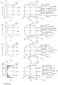
- Figure 2 shows schematically embodiments of precious metal meshes that can be produced with the method according to the invention.
- Figure 2 A and B show a two-layer noble metal net 20' made of two rectangular layers 21' and 22', which are connected along the knitting direction S on both sides and over the entire length of the noble metal net 20'.
- Figure 2B shows an open view of the precious metal mesh 20' along the abutting edge 24' of the first layer 21'. The "opening" is to be understood virtually at this point and serves for a better understanding of the invention.
- the two Butt edges 23' and 26' are separated from one another, the corresponding single-layer precious metal mesh would have the Figure 2B shown shape.
- Section 27' of the length of the precious metal mesh shows the area or the knitting rows via which the two layers are connected to one another at their abutting edges (23' and 24' of the first layer 21' and 25' and 26' of the second layer 22').
- the noble metal net 20' has a tubular structure which is open at the bottom and top.
- a right side row (M1'-H, M2'-H, M3'-H) is knitted on the first needle bed and a wrong side row (M1'-R, M2'-R, M3'-R) on the second needle bed.
- On both sides there is a connection of the back and forth rows (M1'-H - M1'-R, M2'-H - M2'-R, M3'-H - M3'-R) via connecting stitches (M1'-VH, M2'-VH, M3'-VH, M1'-VR M2'-VR, M3'-VR).
- the two sides correspond to the respective abutting edges of the two layers (21', 22') of the precious metal mesh 20'.
- FIG 2C shows the front view of a precious metal mesh 20", which consists of two semicircular layers 21" and 22" (the second layer 22" is shown in perspective in Fig. 2C not visible) is formed.
- Figure 2D again shows a perspective of the precious metal mesh 20" virtually unfolded along the abutting edge 24" and three exemplary knitting rows M1", M2", M3" at different heights along the knitting direction S.
- Both front and back rows of the lower and upper knitting rows M1"-H, M3"-H and M1"-R, M3"-R are shorter, ie comprise fewer stitches than those of the middle knitting row (M2"-H, M2"-R).
- the shape of the precious metal mesh or the shape of the layers can thus be determined by the row of knitting.
- the layers 21" and 22" are connected on both sides over the entire length 27".
- a precious metal mesh 20′′′ is shown formed from two semi-circular plies 21′′′ and 22′′′ which are bonded together on either side only over parts of the length of the precious metal mesh 27′′′. Accordingly, the back and forth rows of the lower and upper knitted rows M1′′′-H, M3′′′-H and M1′′′-R, M3′′′-R are connected to each other only on one side (M1′′′-VH, M3′′′-VH). The abutting edges 23′′′ and 25′′′ can be connected to one another over their entire length.
- FIG. 2 G and H shows a precious metal mesh 20'' made up of a first semi-circular sheet 21'' and a second rectangular sheet 22'' (in Fig. 2G shown hatched) is formed.
- the two layers 21'′′′ and 22'′′′ are connected to one another only over parts of the length 27'′′′.
- a rectangular layer (100 cm wide, 200 cm long) was knitted on each needle bed with a PtRh5 wire (diameter 76 ⁇ m).
- the two layers were only connected to one another on one side by suitable thread guidance, in the example according to the invention on both sides (according to Fig. 2A or. Fig. 2B) .
- a connecting side was separated after the knitting process.
- a noble metal mesh with a width of 200 cm and a length of 200 cm was obtained.
Landscapes
- Chemical & Material Sciences (AREA)
- Engineering & Computer Science (AREA)
- Textile Engineering (AREA)
- Materials Engineering (AREA)
- Organic Chemistry (AREA)
- Chemical Kinetics & Catalysis (AREA)
- Mechanical Engineering (AREA)
- Metallurgy (AREA)
- Knitting Of Fabric (AREA)
Abstract
Description
- Die vorliegende Erfindung betrifft ein Verfahren zur Herstellung eines zweilagigen Edelmetallnetzes auf einer Flachstrickmaschine, die ein erstes und ein zweites Nadelbett aufweist. Das Verfahren umfasst das Bereitstellen von mindestens einem edelmetallhaltigen Draht und das Stricken des Edelmetallnetzes. Auf dem ersten und zweiten Nadelbett werden simultan die erste und die zweite Lage des Edelmetallnetzes gestrickt und diese beiden Teile werden zumindest teilweise an ihren beiden jeweiligen Stoßkanten verbunden.
- Die heterogen edelmetallkatalysierte Oxidation von Ammoniak (NH3) zu Salpetersäure (HNO3, Ostwald-Verfahren) oder Herstellung von Cyanwasserstoff (HCN, Andrussow-Verfahren) ist aufgrund der zentralen Relevanz der Produkte für die chemische Industrie von großer Bedeutung. Die dafür eingesetzten Katalysatorsysteme werden meist in Form von gasdurchlässigen Flächengebilden in die Reaktionszone eines Strömungsreaktors in einer Ebene senkrecht zur Strömungsrichtung des Frischgases eingebaut. Auch Auffang- oder Catchment-Systeme zur Rückgewinnung von verdampften katalytisch aktiven Bestandteilen basieren häufig auf solchen netzförmigen Strukturen. Es werden zweckmäßigerweise meist mehrere Netze hintereinander angeordnet und zu einem Katalysatornetzstapel zusammengefasst. Die einzelnen Netze bestehen dabei aus feinen Edelmetalldrähten, die überwiegend Platin (Pt), Palladium (Pd), Rhodium (Rh) oder Legierungen dieser Metalle enthalten. Vor allem Catchment-Netze können auch weitere Bestandteile wie beispielsweise Nickel enthalten.
- Zur Herstellung solcher Maschenwaren sind eine Reihe von Verfahren bekannt, zum Beispiel das Weben, Wirken und Stricken. Weben und Wirken sind vor allem für die Herstellung rechteckiger Netzbahnen mit homogener Materialverteilung und Struktur geeignet. In Bezug auf die Formgestaltung und Materialvariabilität der zu fertigenden Produkte bieten sie wenig Flexibilität. Aus den gefertigten Bahnen müssen in einem zusätzlichen Verfahrensschritt die Netze auf für die Reaktoren geeignete Größe und Form zugeschnitten werden, wobei Verschnitt mit Edelmetallbestandteilen entsteht. Außerdem erfordern die eingesetzten Maschinen lange Rüstzeiten und einen hohen Materialeinsatz.
- Das Stricken bietet im Vergleich eine höhere Flexibilität: über die verwendeten Strickmuster, Drähte (z.B. was Dicke und Material betrifft), Nadeln und Zugspannung des Drahtes kann sowohl das Flächengewicht als auch die Struktur, Dehnbarkeit und Festigkeit der erhältlichen Gestricke variiert werden. Ein weiterer Vorteil sind die deutlich kürzeren Rüstzeiten der Maschinen. Außerdem ist die Verwendung unterschiedlicher Materialien in einem Gestrick möglich, beim s.g. Intarsien-Stricken werden beispielsweise unterschiedliche Bereiche aus unterschiedlichen Garnen oder Drähten gefertigt. Die Länge eines Gestricks ist dabei prinzipiell nicht begrenzt, die maximale Breite ist jedoch im Fall von Flachstrickmaschinen durch die Breite der Nadelbetten vorgegeben.
- Beim Stricken können Flachstrickmaschinen oder Rundstrickmaschinen zum Einsatz kommen. Bei Rundstrickmaschinen sind die Nadeln in einem kreisförmigen Nadelbett angeordnet und die Faden- bzw. Drahtzuführung erfolgt entsprechend in einer kreisförmigen Bewegung. Solche Maschinen erlauben vor allem die Herstellung von schlauchförmigen Strickwaren. Auf Flachstrickmaschinen dagegen können Form und Maß der Gestricke variiert werden. Letztere können auch über mehr als ein Nadelbett verfügen, zwischen denen bei der Fertigung das Garn bzw. der Draht mittels Fadenführern hin- und her geführt wird.
- Die Verwendung von zwei Nadelbetten erlaubt die Herstellung eines einlagigen oder zweilagigen Gestricks. Ein einlagiges Gestrick kann prinzipiell auf zwei Arten entstehen: Einerseits, wenn nur auf einem Nadelbett gearbeitet wird, d.h. nur Maschen auf einem der Nadelbetten gebildet und miteinander verstrickt werden. Andererseits können auf dem ersten Nadelbett erzeugte Maschen mit auf dem zweiten Nadelbett erzeugten Maschen verstrickt werden, d.h. der Faden wird innerhalb einer Hin- und/oder Rückreihe zwischen den beiden Nadelbetten hin- und her geführt. Ein zweilagiges Gestrick entsteht dementsprechend, wenn parallel auf beiden Nadelbetten gestrickt wird und die auf der ersten Nadelreihe erzeugten Maschen nicht oder nur punktuell mit den auf dem zweiten Nadelbett erzeugten Maschen über die Randmaschen verstrickt werden. Bei dieser Herstellungsweise können also auch zwei einlagige Gestricke bzw. Lagen parallel auf dem ersten und zweiten Nadelbett gefertigt werden.
- Das Stricken von Edelmetallnetzen ist in der
EP 0544710 A1 beschrieben. In derEP 3795728 A1 kommen dafür Flachstrickmaschinen zum Einsatz. Es wird beschrieben, dass separate Lagen, erzeugt auf unterschiedlichen Nadelbetten, mittels einer verbindenden Maschenreihe an einer Seite der beiden Strickflächen miteinander verbunden werden können. Das erlaube die Herstellung von Gestrickflächen mit größeren Breiten als vorher möglich. - Es hat sich allerdings gezeigt, dass eine solche einseitige Verbindung zum Verziehen des Gestricks und dadurch zu Instabilitäten im Produktionsprozess führen kann. Solche Instabilitäten können sich einerseits in Abrissen des Drahtes während des Strickprozesses und andererseits durch ein Produkt mit mangelnder Qualität aufgrund von Unregelmäßigkeiten in Bezug auf die Struktur und die mechanischen Eigenschaften äußern.
- Aufgabe der vorliegenden Erfindung war daher die Bereitstellung eines Verfahrens zur Herstellung von Edelmetallnetzen auf Flachstrickmaschinen mit hoher Prozessstabilität.
- Die Aufgabe wird gelöst durch ein Verfahren zur Herstellung eines zweilagigen Edelmetallnetzes auf einer Flachstrickmaschine, wobei die Flachstrickmaschine ein erstes und ein zweites Nadelbett aufweist, umfassend die Schritte
- Bereitstellen von mindestens einem edelmetallhaltigen Draht,
- Stricken des Edelmetallnetzes,
- Im Rahmen der Erfindung wurde erkannt, dass durch eine zumindest teilweise beidseitige Verbindung von Gestrickteilen aus Edelmetalldrähten auf unterschiedlichen Nadelbetten die Stabilität des Strickprozesses erhöht werden kann. Dadurch werden formstabile Gestricke erhalten, die zumindest teilweise eine offene Schlauchstruktur aufweisen. Durch die Stabilisierung des Strickprozesses kann außerdem die volle summierte Breite der beiden Nadelbetten einer Flachstrickmaschine ausgenutzt werden.
- Das erfindungsgemäße Verfahren betrifft das Stricken auf einer Flachstrickmaschine mit einem ersten und einem zweiten Nadelbett.
- Stricken ist charakterisiert durch die reihenweise Herstellung der entstehenden Gestricke, bei der ineinandergreifende Maschen gebildet werden. Während des Strickvorgangs auf einer Flachstrickmaschine mit zwei Nadelbetten wird zunächst eine Strickreihe auf mindestens einem der Nadelbetten gebildet. In Strickrichtung wird im Anschluss die nächste Strickreihe gebildet, wobei im Folgenden auf den Teil des Gestricks, der die erste Strickreihe enthält als "unten" Bezug genommen wird. Die Faden- bzw. Drahtführung erfolgt von einer Seite des Nadelbettes oder der Nadelbetten zur anderen Seite und zurück. Wenn im Folgenden Bezug auf einen "Faden" genommen wird soll die jeweilige Ausführung auch für einen entsprechenden "Draht" gelten. Eine Strickreihe umfasst daher eine Hin- und eine Rückreihe, was sich aus der Fadenführung ergibt. Die Fadenführung kann dabei in einer Strickreihe über nur eines oder beide Nadelbetten erfolgen. Typischerweise kann der Faden für eine vollständige Strickreihe zunächst auf dem ersten Nadelbett geführt werden (Hinreihe), anschließend wird der Faden in entgegengesetzte Richtung auf dem gleichen Nadelbett oder dem zweiten Nadelbett geführt (Rückreihe). Der Faden kann aber auch in einer Hin- und/oder Rückreihe abwechselnd auf beiden Nadelbetten geführt werden, wobei innerhalb einer Strickreihe Verbindungen zwischen Maschen auf den beiden Nadelbetten erzeugt werden. Die Fadenführung kann über die gesamte Breite des Nadelbetts bzw. der Nadelbetten erfolgen, es kann aber auch nur über Teile der Breite der Nadelbetten gestrickt werden. Je nachdem über welche Breite der Nadelbetten gestrickt wird kann die Breite und auch die Form des Gestricks bestimmt werden.
- Das Verfahren umfasst das Bereitstellen von mindestens einem edelmetallhaltigen Draht.
- Unter einem edelmetallhaltigen Draht wird ein Draht verstanden, der aus mindestens einem Edelmetall besteht oder einen nennenswerten Anteil (> 50 Gew.-%) an Edelmetall enthält. Unter Edelmetallen wird im Rahmen der vorliegenden Erfindung ein Metall ausgewählt aus der Gruppe bestehend aus Platinmetallen, Gold und Silber verstanden. Unter Platinmetallen sind die Metalle der sogenannten Platingruppe, also Platin (Pt), Palladium (Pd), Iridium (Ir), Rhodium (Rh), Osmium (Os) und Ruthenium (Ru), zu verstehen.
- Bevorzugt besteht der mindestens eine edelmetallhaltige Draht aus Platin, einer Platinlegierung, Palladium oder einer Palladiumlegierung. Eine platinbasierte Legierung enthält mehr als 50 Gew.-% Platin, als weitere Legierungsbestandteile sind insbesondere Palladium, Rhodium und Ruthenium zu nennen. Eine palladiumbasierte Legierung enthält mehr als 50 Gew.-% Palladium.
- Bevorzugt besteht der mindestens eine edelmetallhaltige Draht aus einer Legierung ausgewählt aus der Gruppe bestehend aus Platin mit 1 - 15 Gew.-% Rhodium, Platin mit 1 - 15 Gew.-% Rhodium und 0,1 - 20 Gew.-% Palladium, Platin mit 1 - 15 Gew.-% Rhodium, 0,1 - 20 Gew.-% Palladium und 0,1 - 5 Gew.-% Ruthenium, Platin mit 1 - 15 Gew.-% Rhodium, 0,1 - 40 Gew.-% Palladium und 0,001 - 5 Gew.-% Iridium, Platin mit 1 - 15 Gew.-% Rhodium, 0,1 - 20 Gew.-% Palladium und 0,001 - 5 Gew.-% Tantal, Platin mit 1 - 15 Gew.-% Rhodium, 0,001 - 5 Gew% Iridium und 0,001 - 5 Gew.-% Tantal, Palladium mit 1 - 25 Gew.-% Platin, Palladium mit 1 - 20 Gew.-% Platin und 1 - 15 Gew.-% Rhodium, Palladium mit 1 - 25 Gew.-% Wolfram, Palladium mit 1 - 15 Gew.-% Nickel, Palladium mit 0,001 - 5 Gew.-% Rhodium, Palladium mit 1 - 15 Gew.-% Kupfer, Palladium mit 1 - 15 Gew.-% Kupfer und 1 - 15 Gew.-% Nickel und Palladium mit 1 - 30 Gew.-% Cobalt.
- Vorzugsweise werden edelmetallhaltige Drähte eingesetzt, die einen Durchmesser 40 - 150 µm aufweisen, bevorzugt 50 - 130 µm.
- Der mindestens eine edelmetallhaltige Draht kann als Runddraht, das heißt mit einem runden Querschnitt, ausgebildet sein. In einer anderen Ausführung kann der Draht als abgeflachter Runddraht oder als Draht mit einem anderen Querschnitt ausgeführt werden.
- Der mindestens eine edelmetallhaltige Draht kann mehrere Drähte, in diesem Fall auch als Filamente bezeichnet, umfassen, die bevorzugt miteinander verdrillt sein können. Die Filamente können alle aus dem gleichen Material bestehen, d.h. alle edelmetallhaltig sein, oder aus unterschiedlichen Materialien bestehen, die wiederum nicht alle edelmetallhaltig sein müssen.
- In vielen Fällen kann es vorteilhaft sein, zwei oder mehr edelmetallhaltige Drähte gemeinsam miteinander zu verstricken. Mit anderen Worten können bei der Bildung einer Masche mehrere edelmetallhaltige Drähte gemeinsam geführt werden. Beim Stricken mit mehreren Drähten bestehen in einer Ausführungsform die edelmetallhaltigen Drähte aus dem gleichen Material, in weiteren Ausführungsformen können edelmetallhaltige Drähte bestehend aus mindestens zwei unterschiedlichen Materialien verwendet werden. Die mehreren Drähte können den gleichen oder unterschiedliche Durchmesser aufweisen.
- Im erfindungsgemäßen Verfahren werden simultan auf dem ersten Nadelbett eine erste Lage des zweilagigen Edelmetallnetzes und auf dem zweiten Nadelbett eine zweite Lage des zweilagigen Edelmetallnetzes gestrickt. Mit anderen Worten werden während des Strickvorgangs gleichzeitig zwei Teile des zu fertigenden zweilagigen Edelmetallnetzes auf jeweils einem Nadelbett gestrickt, die Fertigung der beiden Lagen erfolgt also nicht nacheinander.
- Unter "zweilagigen Edelmetallnetzen" werden im Rahmen der vorliegenden Erfindung solche Edelmetallnetze verstanden, die über zwei Lagen verfügen, wobei die Lagen im Allgemeinen über eine oder mehrere ihrer jeweiligen Stoßkanten miteinander verbunden sein können oder auch nicht an ihren Stoßkanten verbunden sein können. Die beiden Lagen liegen dabei übereinander, das heißt sie überlappen zumindest teilweise im Bereich ihrer Flächenausdehnung. Auch Edelmetallnetze die, wie im Fall der vorliegenden Erfindung, an einer Seite über die Stoßkanten der zwei Lagen miteinander verbunden sind werden als zweilagige Edelmetallnetze bezeichnet. Bei einem Aufklappen entlang der gemeinsamen Stoßkante ist ein einlagiges Edelmetallnetz erhältlich.
- Die erste und die zweite Lage des zweilagigen Edelmetallnetzes verfügen jeweils über mindestens zwei Stoßkanten, d.h. jede Lage verfügt auf der einen Seite über eine Stoßkante und auf ihrer anderen Seite über eine weitere Stoßkante. Die Seiten der Edelmetalllagen sind hierbei in Bezug auf die Lage der Stoßkanten auf den beiden Nadelbetten senkrecht zur Strickrichtung zu verstehen. Je nach Form der jeweiligen Lage können sich die Stoßkanten einer Lage nicht schneiden, wie im Fall einer rechteckigen Lage, oder sich schneiden, wie beispielsweise im Fall einer halbkreisförmigen Lage. Die Stoßkanten werden während des Strickvorgangs in Strickrichtung von unten nach oben gebildet. Die beiden Edelmetalllagen können auch über eine obere und/oder untere Kante oder Stoßkante verfügen, das Vorhandensein dieser Kanten hängt von der Form der jeweiligen Lage ab. Eine rechteckige Lage verfügt neben den beiden seitlichen Stoßkanten beispielsweise über eine untere und eine obere Kante oder Stoßkante, eine halbkreisförmige Lage verfügt dagegen über keine weiteren Kanten oder Stoßkanten.
- Unter den unteren Kanten oder Stoßkanten sind hierbei diejenigen Kanten oder Stoßkanten zu verstehen, die in Strickrichtung zuerst gebildet werden, sich also unten im Gestrick befinden. Dementsprechend sind unter den oberen Kanten oder Stoßkanten diejenigen zu verstehen, die in Strickrichtung später gebildet werden. Der Bezug für die Höhe des Gestricks, auf die im Folgenden Bezug genommen werden wird, ist die untere Strickreihe des Gestricks. Auch für den Fall, dass in unterschiedlichen Strickreihen mit dem Stricken einer Lage begonnen wird bleibt die Höhe des Gesamtstricks gleich, mit anderen Worten können die Lagen des Gestricks auf unterschiedlichen Höhen eine unterschiedliche Anzahl von Strickreihen umfassen.
- Die erste und die zweite Lage des zweilagigen Edelmetallnetzes werden durch mindestens eine verbindende Strickmasche zumindest teilweise an ihren beiden jeweiligen Stoßkanten verbunden. Darunter ist zu verstehen, dass die beiden Lagen über Maschen, die aus dem mindestens einen edelmetallhaltigen Draht gebildet werden, miteinander verbunden werden. Durch diese Verbindungen entsteht ein zumindest teilweise schlauchartiges Gestrick.
- Die Verbindung der beiden Edelmetallnetzlagen erfolgt auf beiden Seiten zumindest über Teile ihrer jeweiligen Stoßkanten, wobei diese teilweise Verbindungen auf gleicher Höhe, also in der gleichen Strickreihe oder den gleichen Strickreihen oder auf unterschiedlichen Höhen erfolgen kann. Die teilweisen Verbindungen können über die gleiche Länge auf beiden Seiten erfolgen, also über die gleiche Anzahl von Strickreihen. Die teilweisen Verbindungen können aber auch über eine unterschiedliche Länge auf beiden Seiten erfolgen.
- In einer bevorzugten Ausführungsform erfolgen die teilweisen Verbindungen zumindest teilweise in den gleichen Strickreihen. In einer solchen Ausführungsform kann also zumindest teilweise im Kreis gestrickt bzw. rundgestrickt werden, mit anderen Worten entsteht über diese Strickreihen eine ringartige Struktur. Es hat sich gezeigt, dass das Stricken einer solchen zumindest teilweise ringartigen Struktur die Stabilität des Strickprozesses positiv beeinflussen kann.
- Bevorzugt kann die erste und die zweite Lage des zweilagigen Edelmetallnetzes aus einem edelmetallhaltigen Draht oder edelmetallhaltigen Drähten gleicher Zusammensetzung gestrickt werden. Die beiden Lagen können aber auch aus edelmetallhaltigem Draht oder edelmetallhaltigen Drähten unterschiedlicher Zusammensetzung gestrickt werden.
- Zum Stricken der ersten und zweiten Lage des zweilagigen Edelmetallnetzes kann edelmetallhaltiger Draht mit dem gleichen oder unterschiedlichen Durchmessern verwendet werden. Es hat sich als günstig erwiesen, dass die erste und die zweite Lage des zweilagigen Edelmetallnetzes aus einem edelmetallhaltigen Draht oder edelmetallhaltigen Drähten gleichen Durchmessers gestrickt werden.
- Die erste und die zweite Lage des zweilagigen Edelmetallnetzes können in gleichen oder unterschiedlichen Strickmustern gestrickt werden. Unterschiedliche Strickmuster können beispielsweise durch unterschiedliche Maschenlängen, Flottungen oder Fänge entstehen. In bevorzugten Ausführungsformen werden die erste und die zweite Lage des zweilagigen Edelmetallnetzes im gleichen Strickmuster gestrickt.
- Die erste und die zweite Lage des zweilagigen Edelmetallnetzes können die gleiche oder unterschiedliche Längen in Strickrichtung und/oder die gleiche oder unterschiedliche Breiten senkrecht zur Strickrichtung aufweisen. Bevorzugt haben die erste und die zweite Lage des Edelmetallnetzes die gleiche Länge und die gleiche Breite.
- Die erste und die zweite Lage des zweilagigen Edelmetallnetzes können die gleiche Form oder unterschiedliche Formen haben. Besonders bevorzugt haben die erste und zweite Lage des zweilagigen Edelmetallnetzes die gleiche Form. Es kann vorteilhaft sein, dass die erste und die zweite Lage des zweilagigen Edelmetallnetzes die Form eines Halbkreises aufweisen, der an einer Seite abgeflacht sein kann. Besonders vorteilhaft kann sein, dass diese beiden Halbkreise die gleiche Breite und die gleiche Länge aufweisen.
- In bevorzugten Ausführungsformen sind die erste und die zweite Lage des zweilagigen Edelmetallnetzes deckungsgleich, mit anderen Worten können die beiden Lagen die gleiche Länge, die gleiche Breite und die gleiche Form haben.
- Es kann vorteilhaft sein, dass im erfindungsgemäßen Verfahren zusätzlich ein Stützfaden zum Einsatz kommt. Solche Stützfäden können eingesetzt werden, um das entstehende Gestrick oder das Verfahren zu stabilisieren, zum Beispiel um das Abreißen des edelmetallhaltigen Drahtes zu verhindern. Geeignete Stützfäden können durch Routineversuche und unter Berücksichtigung des endgültigen Verwendungszwecks des zweilagigen Edelmetallnetzes und eventuellen zusätzlichen Schritten im Herstellverfahren ausgewählt werden. Bevorzugte Stützfäden lassen sich nach der Herstellung des zweilagigen Edelmetallnetzes entfernen, beispielsweise durch Auflösen in sauren oder basischen Medien, Abschneiden, Schmelzen oder Abflammen. Solche Stützfäden können natürlicher oder synthetischer organischer Natur oder anorganischer Natur sein. Beispiele für geeignete Materialien sind Polyamide, Polyester, Zellulosefasern, Baumwolle, Acryl-Styrol-Polymere, Nylon, PVA und andere Vinylpolymere, Alginat, Kupfer, Silber, Aluminium, oder auch Metalle mit niedrigem Schmelzpunkt wie Zinn- und Blei-Legierungen.
- Das Verfahren kann das simultane Stricken eines Stütznetzes unter Verwendung des Stützfadens umfassen. Mit anderen Worten kann das Stütznetz gleichzeitig mit den beiden Lagen des zu fertigenden zweilagigen Edelmetallnetzes gestrickt werden, die Fertigung der beiden Lagen und des Stütznetzes erfolgt also nicht nacheinander. Es kann bevorzugt sein, das Stütznetz zumindest teilweise auf dem ersten und dem zweiten Nadelbett zu stricken.
- Unter "Stütznetz" werden die Bereiche des Gestricks verstanden, die zumindest teilweise unter Verwendung des Stützfadens gestrickt werden. Das Gestrick umfasst alle Strickreihen, die während des Verfahrens gebildet werden. Das Gestrick umfasst mindestens die erste und zweite Lage des zweilagigen Edelmetallnetzes. Das Gestrick kann aber auch weitere Teile oder Bereiche umfassen, beispielsweise ein Stütznetz.
- Das Stütznetz kann auch weitere Fäden oder Drähte umfassen.
- Der Stützfaden kann parallel mit dem mindestens einen edelmetallhaltigen Draht verstrickt werden, d.h. es können beim Stricken Maschen gebildet werden, die edelmetallhaltigen Draht und Stützfaden umfassen. Der betreffende Teil des entstehenden Gestricks enthält in diesen Fällen sowohl Edelmetall als auch das Material des Stützfadens. In anderen Ausführungsformen kann der Stützfaden auch für Teile oder Bereiche des Gestricks eingesetzt werden, die keinen edelmetallhaltigen Draht enthalten, d.h. das entstehende Gestrick enthält in diesen Fällen Teile mit und Teile ohne edelmetallhaltigen Draht. Diese Ausführungsformen können auch miteinander kombiniert werden.
- Das Stütznetz kann dementsprechend mehrere Bereiche umfassen. Beispielsweise kann das Stütznetz auch Strickreihen umfassen, in denen kein edelmetallhaltiger Draht eingesetzt wird, in denen also nur mit dem Stützfaden gestrickt wird. Mit anderen Worten kann das Gestrick Bereiche umfassen, die keinen edelmetallhaltigen Draht enthalten. Das Gestrick kann auch über Strickreihen verfügen, die nur von Bereichen des Stütznetzes gebildet werden.
- Die Form des Stütznetzes ist nicht weiter beschränkt. Es hat sich aber als vorteilhaft erwiesen, dass die Form des Stütznetzes so gestaltet ist, dass die Form des Gestrickes insgesamt rechteckig ist. Mit anderen Worten kann das Stütznetz die Lagen des Edelmetallnetzes derart ergänzen, dass die Form des Gestricks umfassend Edelmetalllage oder Edelmetalllagen und Stütznetz insgesamt eine rechteckige Form aufweist.
- Es kann bevorzugt sein, dass das Stütznetz in den Bereichen, die keinen edelmetallhaltigen Draht enthalten, zweilagig gestrickt wird. Mit anderen Worten kann das Stütznetz in diesen Strickreihen nicht mit verbindenden Maschen zwischen dem ersten und zweiten Nadelbett gestrickt werden. Diese beiden Lagen können an den Randmaschen über verbindende Strickmaschen verbunden sein, es kann also vorteilhaft sein, dass das Stütznetz in diesen Bereichen eine schlauchartige Struktur hat. Bevorzugt kann auch sein, dass das Stütznetz in den Bereichen, die keinen edelmetallhaltigen Draht umfassen, einlagig gestrickt wird.
- In bevorzugten Ausführungsformen umfasst das Stütznetz einlagig gestrickte Bereiche und zweilagig gestrickte Bereiche, die keinen edelmetallhaltigen Draht umfassen.
- Es kann vorteilhaft sein, dass das Stütznetz die beiden Lagen des zweilagigen Edelmetallnetzes an mehr als einer Seite umgibt. In bevorzugten Ausführungsformen umgibt das Stütznetz die beiden Lagen des zweilagigen Edelmetallnetzes zu mindestens 50 %. Darunter ist zu verstehen, dass mindestens 50 % des Umfangs der beiden Lagen des zweilagigen Edelmetallnetzes vom Stütznetz umgeben sind, bevorzugter mindestens 60 %, noch bevorzugter mindestens 80 %. Besonders bevorzugt kann sein, dass das Stütznetz die beiden Lagen des zweilagigen Edelmetallnetzes vollständig umgibt.
- Bevorzugt können alle Bereiche des Stütznetzes aus Stützfäden der gleichen Zusammensetzung gestrickt werden. Unterschiedliche Bereiche können aber auch aus Stützfäden unterschiedlicher Zusammensetzung gestrickt werden. Unterschiedliche Bereiche des Stütznetzes können in gleichen oder unterschiedlichen Strickmustern gestrickt werden.
- Vorteilhaft kann sein, das Stütznetz in einem zusätzlichen Verfahrensschritt zu entfernen, beispielsweise zu zersetzen, aufzulösen, schmelzen, abzuflammen oder abzuschneiden.
- Das erfindungsgemäße Verfahren kann weitere Schritte umfassen.
- Das Verfahren kann das Bereitstellen von mindestens einem weiteren Draht oder Faden umfassen. Geeignete weitere Drähte oder Fäden können je nach vorgesehener Verwendung und/oder Funktion im Herstellverfahren oder für die spätere Anwendung des Edelmetallnetzes ausgewählt werden. Beispielsweise kann es sich bei dem weiteren Draht um einen Draht aus einem Nicht-Edelmetall handeln, der geeignet ist, um das Edelmetallnetz beim Einsatz im Reaktor zu stabilisieren. Zum Beispiel kann es sich dabei um einen Stahl- oder Edelstahldraht handeln. Das Verfahren umfasst in diesen Fällen das simultane Stricken von Bereichen des Gestricks unter Verwendung des mindestens einen weiteren Drahtes oder Fadens. Das Gestrick kann in diesem Fall Teile oder Bereiche umfassen, die nur den weiteren Draht oder Faden enthalten oder Teile oder Bereiche, die sowohl den weiteren Draht oder Faden als auch den edelmetallhaltigen Draht und/oder einen Stützfaden enthalten.
- In einem weiteren Schritt können die verbindende Masche oder die verbindenden Maschen zwischen der ersten und zweiten Lage des zweilagigen Edelmetallnetzes an einer Seite entfernt werden, mit anderen Worten werden die beiden Lagen an einer Seite getrennt. Dadurch entsteht ein Edelmetallnetz, das nur noch an einer Seite, d.h. über jeweils nur eine Stoßkante, der beiden Lagen zumindest teilweise verbunden ist. Mit anderen Worten ist so ein einlagiges Edelmetallnetz herstellbar.
- Nachfolgend wird die Erfindung anhand von Abbildungen und einem Beispiel näher erläutert. Sie ist jedoch nicht auf diese Ausführungsformen beschränkt.
- Abbildung 1
- zeigt einen Strömungsreaktor zur heterogen-katalytischen Verbrennung von Ammoniak in schematischer Darstellung,
- Abbildung 2
- zeigt Ausführungsformen von Edelmetallnetzen, die mit dem erfindungsgemäßen Verfahren hergestellt werden können.
-
Abbildung 1 zeigt schematisch einen senkrecht positionierten Strömungsreaktor 1 zur heterogen-katalytischen Verbrennung von Ammoniak. Das Katalysatorsystem 2 bildet die eigentliche Reaktionszone des Strömungsreaktors 1. Es umfasst eine Katalysatorpackung 3 und nachgeschaltete Catchment-Netze 4. Die Katalysatorpackung 3 umfasst mehrere, in Strömungsrichtung 5 des Frischgases hintereinander angeordnete Katalysatornetze 6. Typischerweise sind die Katalysatornetze 6 gestrickte Netze, die beispielsweise durch Verstricken von Draht mit einem Durchmesser von 76 µm aus verschiedenen Platin-RhodiumLegierungen hergestellt werden. Zusätzlich können Catchment-Netze 4 vorgesehen sein. -
Abbildung 2 zeigt schematisch Ausführungsformen von Edelmetallnetzen, die mit dem erfindungsgemäßen Verfahren hergestellt werden können. -
Abbildung 2 A und B zeigen ein zweilagiges Edelmetallnetzes 20' aus zwei rechteckigen Lagen 21' und 22', die an beiden Seiten und über die gesamte Länge des Edelmetallnetzes 20' entlang der Strickrichtung S verbunden sind. In der frontalen Ansicht inAbbildung 2 A ist nur die erste Lage 21' sichtbar.Abbildung 2 B zeigt eine entlang der Stoßkante 24' der ersten Lage 21' geöffnete Sicht des Edelmetallnetzes 20'. Das "Öffnen" ist an dieser Stelle virtuell zu verstehen und dient dem besseren Verständnis der Erfindung. Für den Fall, dass nach der Herstellung des zweilagigen Edelmetallnetzes 20' ein weiterer Verfahrensschritt erfolgt, in dem die beiden Stoßkanten 23' und 26' voneinander getrennt werden, hätte das entsprechende einlagige Edelmetallnetz die inAbbildung 2 B gezeigte Form. Außerdem gezeigt sind die Position von exemplarischen Strickreihen M1', M2', M3' entlang der Strickrichtung S auf verschiedenen Höhen des Edelmetallnetzes 20', deren Positionen im Edelmetallnetz 20' durch gestrichelte Linien angedeutet sind. Der Abschnitt 27' der Länge des Edelmetallnetzes zeigt den Bereich bzw. die Strickreihen über die die beiden Lagen an ihren Stoßkanten (23' und 24' der ersten Lage 21' und 25' und 26' der zweiten Lage 22') miteinander verbunden werden. Das Edelmetallnetz 20' hat eine schlauchartige Struktur, die am unteren und oberen Ende offen ist. Im Fall der Ausführungsform eines Edelmetallnetzes gemäßAbbildung 2 A und B wird jeweils eine Hinreihe (M1'-H, M2'-H, M3'-H) auf dem ersten Nadelbett und eine Rückreihe (M1'-R, M2'-R, M3'-R) auf dem zweiten Nadelbett gestrickt. Auf beiden Seiten erfolgt eine Verbindung der Hin- und Rückreihe (M1'-H - M1'-R, M2'-H - M2'-R, M3'-H - M3'-R) über verbindende Maschen (M1'-VH, M2'-VH, M3'-VH, M1'-VR M2'-VR, M3'-VR). Die beiden Seiten entsprechen den jeweiligen Stoßkanten der beiden Lagen (21', 22') des Edelmetallnetzes 20'. -
Abbildung 2 C zeigt die Frontansicht eines Edelmetallnetzes 20", das aus zwei halbrunden Lagen 21" und 22" (die zweite Lage 22" ist in der Perspektive inAbb. 2 C nicht sichtbar) gebildet wird.Abbildung 2 D zeigt wiederum eine virtuell entlang der Stoßkante 24" aufgeklappte Perspektive des Edelmetallnetzes 20" und drei exemplarische Strickreihen M1", M2", M3" in verschiedenen Höhen entlang der Strickrichtung S. Sowohl Hin- als auch Rückreihen der unteren und oberen Strickreihe M1"-H, M3"-H und M1"-R, M3"-R sind kürzer, d.h. umfassen weniger Maschen, als die der mittleren Strickreihe (M2"-H, M2"-R). Über die Anzahl der Maschen je Strickreihe kann also die Formgebung des Edelmetallnetzes, bzw. die Form der Lagen, bestimmt werden. Die Lagen 21" und 22" sind über die vollständige Länge 27" auf ihren beiden Seiten verbunden. Beim Trennen der Verbindung der beiden Lagen 21" und 22" des Edelmetallnetzes 20" zwischen den Stoßkanten 23' und 26' kann ein Edelmetallnetz mit rundem Querschnitt erhalten werden. - In
Abbildung 2 E und F ist ein Edelmetallnetz 20‴ gezeigt, das aus zwei halbrunden Lagen 21‴ und 22‴ gebildet wird, die nur auf Teilen der Länge des Edelmetallnetzes 27‴ auf beiden Seiten miteinander verbunden sind. Dementsprechend sind die Hin- und Rückreihen der unteren und oberen Strickreihen M1‴-H, M3‴-H und M1‴-R, M3‴-R nur an einer Seite miteinander verbunden (M1‴-VH, M3‴-VH). Die Stoßkanten 23‴ und 25‴ können über ihre vollständige Länge miteinander verbunden sein. - In
Abbildung 2 G und H ist ein Edelmetallnetz 20'‴ gezeigt, das aus einer ersten halbrunden Lage 21'‴ und einer zweiten rechteckigen Lage 22'‴ (inAbb. 2 G schraffiert dargestellt) gebildet wird. Die beiden Lagen 21'‴ und 22'‴ sind nur auf Teilen der Länge 27'‴ miteinander verbunden. - Auf einer Flachstrickmaschine mit zwei Nadelbetten wurde auf jedem Nadelbett mit einem PtRh5 Draht (76 µm Durchmesser) jeweils eine rechteckige Lage (100 cm Breite, 200 cm Länge) gestrickt. Im Vergleichsbeispiel wurden die beiden Lagen durch geeignete Fadenführung nur an einer Seite miteinander verbunden, im erfindungsgemäßen Beispiel an beiden Seiten (gemäß
Abb. 2 A bzw.Abb. 2 B) . Im letztgenannten Fall wurde nach dem Strickvorgang eine verbindende Seite aufgetrennt. In beiden Fällen wurde ein Edelmetallnetz mit einer Breite von 200 cm und einer Länge von 200 cm erhalten. - Trotz des zusätzlichen Arbeitsschrittes beim erfindungsgemäß hergestellten Produkt erwies sich das Verfahren als schneller und zuverlässiger. Während des Strickvorgangs des Vergleichsbeispiels traten immer wieder Drahtrisse auf, die eine Unterbrechung der Herstellung zur Folge hatten. Zusätzlich zu den notwendig werdenden Reparaturstellen des Drahtes wies das Gestrick außerdem eine ungleichmäßige verzogene Struktur auf. Solche Ungleichmäßigkeiten im Gestrick stellen potenziell mechanische Schwachstellen dar, die sich im der Anwendung des Netzes im Reaktor negativ auswirken.
Definition der verwendeten Bezugszeichen 1 Strömungsreaktor 2 Katalysatorsystem 3 Katalysatorpackung 4 Catchment-Netze 5 Strömungsrichtung 6 einlagige Katalysatornetze 20', 20", 20‴, 20"" Gestricktes Edelmetallnetz 21', 21", 21‴, 21"" Erste Lage eines Edelmetallnetzes 22', 22", 22‴, 22"" Zweite Lage eines Edelmetallnetzes 23', 23", 23‴, 23"" Stoßkanten der Edelmetallnetzlagen 24', 24", 24‴, 24"" 25', 25", 25‴, 25"" 26', 26", 26‴, 26"" 27', 27", 27‴, 27ʺʺ Bereiche des Edelmetallnetzes, die auf beiden Seiten verbunden sind M1', M1", M1‴, M1‴ Untere Strickreihe M2', M2", M2‴, M2′‴ Mittlere Strickreihe M3', M3", M3‴, M3′‴ Obere Strickreihe M1'-H, M1"-H, M1‴-H, M1""-H Hinreihe M2'-H, M2"-H, M2‴-H, M2""-H M3'-H, M3"-H, M3‴-H, M3""-H M1'-R, M1"-R, M1‴-R, M1′‴-R Rückreihe M2'-R, M2"-R, M2‴-R, M2′‴-R M3'-R, M3"-R, M3‴-R, M3′‴-R M1'-HR, M1"-HR, M1‴-HR, M1ʺʺ-HR Verbindende Maschen M2'-HR, M2"-HR, M2‴-HR, M2""-HR M3'-HR, M3"-HR, M3‴-HR, M3""-HR M1'-VR, M1"-VR, M1‴-VR, M1′‴-VR M2'-VR, M2"-VR, M2‴-VR, M2ʺʺ-VR M3'-VR, M3"-VR, M3‴-VR, M3ʺ‴-VR S Strickrichtung
wobei beide Lagen jeweils über mindestens zwei Stoßkanten verfügen,
dadurch gekennzeichnet, dass die erste und die zweite Lage des Edelmetallnetzes durch mindestens eine verbindende Strickmasche zumindest teilweise an ihren beiden jeweiligen Stoßkanten verbunden werden.
Claims (10)
- Verfahren zur Herstellung eines zweilagigen Edelmetallnetzes auf einer Flachstrickmaschine, wobei die Flachstrickmaschine ein erstes und ein zweites Nadelbett aufweist, umfassend die Schritte- Bereitstellen von mindestens einem edelmetallhaltigen Draht,- Stricken des Edelmetallnetzes,wobei simultan auf dem ersten Nadelbett die erste Lage des Edelmetallnetzes und auf dem zweiten Nadelbett die zweite Lage des Edelmetallnetzes gestrickt werden,wobei beide Lagen jeweils über mindestens zwei Stoßkanten verfügen,
dadurch gekennzeichnet, dassdie erste und die zweite Lage des Edelmetallnetzes durch mindestens eine verbindende Strickmasche zumindest teilweise an ihren beiden jeweiligen Stoßkanten verbunden werden. - Verfahren nach Anspruch 1, wobei die Verbindung zumindest teilweise in den gleichen Strickreihen erfolgt.
- Verfahren nach einem der vorangegangenen Ansprüche, wobei der mindestens eine edelmetallhaltige Draht aus Platin, einer Platinlegierung, Palladium oder einer Palladiumlegierung besteht.
- Verfahren nach einem der vorangegangenen Ansprüche, wobei die erste und die zweite Lage des Edelmetallnetzes aus einem edelmetallhaltigen Draht oder edelmetallhaltigen Drähten gleicher Zusammensetzung gestrickt werden.
- Verfahren nach einem der vorangegangenen Ansprüche, wobei die erste und die zweite Lage des zweilagigen Edelmetallnetzes aus einem edelmetallhaltigen Draht oder edelmetallhaltigen Drähten gleichen Durchmessers gestrickt werden.
- Verfahren nach einem der vorangegangenen Ansprüche, wobei die erste und die zweite Lage des zweilagigen Edelmetallnetzes im gleichen Strickmuster gestrickt werden.
- Verfahren nach einem der vorangegangenen Ansprüche, wobei die erste und zweite Lage des zweilagigen Edelmetallnetzes deckungsgleich sind.
- Verfahren nach einem der vorangegangenen Ansprüche, wobei das Verfahren das simultane Stricken eines Stütznetzes unter Verwendung eines Stützfadens umfasst.
- Verfahren nach Anspruch 8, wobei das Stütznetz in einem zusätzlichen Verfahrensschritt entfernt wird.
- Verfahren nach einem der vorangegangenen Ansprüche, wobei in einem weiteren Schritt die verbindende Masche oder die verbindenden Maschen zwischen der ersten und zweiten Lage des zweilagigen Edelmetallnetzes an einer Seite entfernt werden.
Priority Applications (5)
| Application Number | Priority Date | Filing Date | Title |
|---|---|---|---|
| EP22152843.3A EP4215662B1 (de) | 2022-01-24 | 2022-01-24 | Verfahren zur herstellung von edelmetallnetzen auf flachstrickmaschinen |
| PL22152843.3T PL4215662T3 (pl) | 2022-01-24 | 2022-01-24 | Sposób wytwarzania siatek z metali szlachetnych na płaskich maszynach dziewiarskich |
| PCT/EP2022/080424 WO2023138805A1 (de) | 2022-01-24 | 2022-11-01 | Verfahren zur herstellung von edelmetallnetzen auf flachstrickmaschinen |
| CN202280089926.5A CN118591664B (zh) | 2022-01-24 | 2022-11-01 | 用于在平型针织机上生产贵金属网的方法 |
| US18/730,660 US12392062B2 (en) | 2022-01-24 | 2022-11-01 | Method for producing noble metal meshes on flatbed knitting machines |
Applications Claiming Priority (1)
| Application Number | Priority Date | Filing Date | Title |
|---|---|---|---|
| EP22152843.3A EP4215662B1 (de) | 2022-01-24 | 2022-01-24 | Verfahren zur herstellung von edelmetallnetzen auf flachstrickmaschinen |
Publications (2)
| Publication Number | Publication Date |
|---|---|
| EP4215662A1 true EP4215662A1 (de) | 2023-07-26 |
| EP4215662B1 EP4215662B1 (de) | 2024-06-12 |
Family
ID=80001299
Family Applications (1)
| Application Number | Title | Priority Date | Filing Date |
|---|---|---|---|
| EP22152843.3A Active EP4215662B1 (de) | 2022-01-24 | 2022-01-24 | Verfahren zur herstellung von edelmetallnetzen auf flachstrickmaschinen |
Country Status (5)
| Country | Link |
|---|---|
| US (1) | US12392062B2 (de) |
| EP (1) | EP4215662B1 (de) |
| CN (1) | CN118591664B (de) |
| PL (1) | PL4215662T3 (de) |
| WO (1) | WO2023138805A1 (de) |
Families Citing this family (2)
| Publication number | Priority date | Publication date | Assignee | Title |
|---|---|---|---|---|
| EP4215661B1 (de) * | 2022-01-24 | 2024-06-05 | Heraeus Precious Metals GmbH & Co. KG | Verfahren zur herstellung von edelmetallnetzen auf flachstrickmaschinen |
| DE102024121410B4 (de) * | 2024-07-26 | 2026-02-05 | Umicore Ag & Co. Kg | Verfahren zur Herstellung von Edelmetallnetzen zur Ammoniakoxidation |
Citations (4)
| Publication number | Priority date | Publication date | Assignee | Title |
|---|---|---|---|---|
| EP0544710A1 (de) | 1990-07-31 | 1993-06-09 | Pgp Industries, Inc. | Katalysatoren und gettersysteme |
| EP0680787A1 (de) * | 1994-04-06 | 1995-11-08 | Degussa Aktiengesellschaft | Katalysatornetze für Gasreaktionen |
| EP1358010B1 (de) * | 2001-02-08 | 2004-10-06 | Umicore AG & Co. KG | Dreidimensionale, in zwei oder mehreren schichten gestrickte katalysatornetze |
| EP3795728A1 (de) | 2019-09-17 | 2021-03-24 | Umicore Ag & Co. Kg | Stricken von edelmetallnetzen und verfahren mit verwendung dieser netze |
Family Cites Families (14)
| Publication number | Priority date | Publication date | Assignee | Title |
|---|---|---|---|---|
| US2274684A (en) * | 1940-11-16 | 1942-03-03 | Metal Textile Corp | Filter medium and filter body made therefrom |
| EP0364153B1 (de) | 1988-10-12 | 1992-03-04 | Johnson Matthey Public Limited Company | Metallgewebe |
| US5268157A (en) * | 1991-03-16 | 1993-12-07 | Degussa Aktiengesellschaft | Process for the production of catalytic gas permeable nets and process for oxidizing ammonia |
| DE4300791A1 (de) * | 1993-01-14 | 1994-07-21 | Heraeus Gmbh W C | Gewirk aus edelmetallhaltigen Drähten und Verfahren für seine Herstellung |
| US6073467A (en) * | 1994-04-06 | 2000-06-13 | Degussa Aktiengesellschaft | Catalyst gauzes for gaseous reactions |
| DE4423714A1 (de) * | 1994-07-08 | 1996-01-11 | Heraeus Gmbh W C | Gewirk aus edelmetallhaltigen Drähten und Verfahren für seine Herstellung |
| EP3056267A1 (de) * | 2015-02-12 | 2016-08-17 | Umicore AG & Co. KG | Katalysatornetz und Anlage zur katalytischen Oxidation von Ammoniak |
| DE102018120999B4 (de) * | 2018-08-28 | 2020-12-24 | Müller Textil GmbH | Abstandsgewirke |
| EP3779005A1 (de) * | 2019-08-16 | 2021-02-17 | Umicore Ag & Co. Kg | Stricken von edelmetallnetzen unter verwendung von unedelmaterial am rand, damit hergestelltes edelmetallnetz und ein verfahren mit verwendung des edelmetallnetzes |
| EP3900826A1 (de) * | 2020-04-22 | 2021-10-27 | UMICORE AG & Co. KG | Edelmetallnetz fuer die katalysierung von gasphasenreaktionen |
| DE102020120927B4 (de) * | 2020-08-07 | 2024-01-25 | Jens Kopatsch | Verfahren zur Herstellung von Netzen mit Tertiärstruktur zur katalytischen Umsetzung von Fluiden |
| US12616967B2 (en) * | 2020-11-17 | 2026-05-05 | Umicore Ag & Co. Kg | Precious metal mesh for catalyzing gas-phase reactions |
| EP4001483A1 (de) * | 2020-11-17 | 2022-05-25 | UMICORE AG & Co. KG | Edelmetallnetz für die katalysierung von gasphasenreaktionen, sein herstellungsverfahren und seine verwendung in einem ammoniak oxidationsverfahren |
| EP4215661B1 (de) * | 2022-01-24 | 2024-06-05 | Heraeus Precious Metals GmbH & Co. KG | Verfahren zur herstellung von edelmetallnetzen auf flachstrickmaschinen |
-
2022
- 2022-01-24 EP EP22152843.3A patent/EP4215662B1/de active Active
- 2022-01-24 PL PL22152843.3T patent/PL4215662T3/pl unknown
- 2022-11-01 WO PCT/EP2022/080424 patent/WO2023138805A1/de not_active Ceased
- 2022-11-01 CN CN202280089926.5A patent/CN118591664B/zh active Active
- 2022-11-01 US US18/730,660 patent/US12392062B2/en active Active
Patent Citations (4)
| Publication number | Priority date | Publication date | Assignee | Title |
|---|---|---|---|---|
| EP0544710A1 (de) | 1990-07-31 | 1993-06-09 | Pgp Industries, Inc. | Katalysatoren und gettersysteme |
| EP0680787A1 (de) * | 1994-04-06 | 1995-11-08 | Degussa Aktiengesellschaft | Katalysatornetze für Gasreaktionen |
| EP1358010B1 (de) * | 2001-02-08 | 2004-10-06 | Umicore AG & Co. KG | Dreidimensionale, in zwei oder mehreren schichten gestrickte katalysatornetze |
| EP3795728A1 (de) | 2019-09-17 | 2021-03-24 | Umicore Ag & Co. Kg | Stricken von edelmetallnetzen und verfahren mit verwendung dieser netze |
Also Published As
| Publication number | Publication date |
|---|---|
| CN118591664A (zh) | 2024-09-03 |
| US20250137174A1 (en) | 2025-05-01 |
| CN118591664B (zh) | 2026-06-09 |
| EP4215662B1 (de) | 2024-06-12 |
| US12392062B2 (en) | 2025-08-19 |
| WO2023138805A1 (de) | 2023-07-27 |
| PL4215662T3 (pl) | 2024-08-05 |
Similar Documents
| Publication | Publication Date | Title |
|---|---|---|
| DE69309470T2 (de) | Fäden aus einem spiralförmigen element, deren anordnung und verwendung dieser anordnung als katalysator bzw. zur zurückgewinnung von edelmetallen | |
| DE4206199C1 (de) | ||
| EP4215662B1 (de) | Verfahren zur herstellung von edelmetallnetzen auf flachstrickmaschinen | |
| EP2689841B1 (de) | Katalysator | |
| EP4215661B1 (de) | Verfahren zur herstellung von edelmetallnetzen auf flachstrickmaschinen | |
| EP4031699B1 (de) | Verfahren zum stricken von edelmetallnetzen | |
| EP4248008B1 (de) | Edelmetallnetz für die katalysierung von gasphasenreaktionen, sein herstellungsverfahren und seine verwendung in einem ammoniak oxidationsverfahren | |
| WO2020148144A1 (de) | Katalysatorsystem sowie verfahren zur katalytischen verbrennung von ammoniak zu stickstoffoxiden in einer mitteldruckanlage | |
| EP4247554B1 (de) | Edelmetallnetz für die katalysierung von gasphasenreaktionen | |
| EP4464828A1 (de) | Verfahren zur herstellung von edelmetallnetzen auf flachstrickmaschinen | |
| DE4305547C2 (de) | Drahtgestrickschlauch sowie Verfahren und Vorrichtung zu dessen Herstellung | |
| EP4344773A1 (de) | Katalysatorsystem mit einem katalysatornetz umfassend einen edelmetalldraht für lange kampagnen in der ammoniakoxidation | |
| DE102024121410B4 (de) | Verfahren zur Herstellung von Edelmetallnetzen zur Ammoniakoxidation | |
| EP4407083A1 (de) | Fadenführer für eine strickmaschine für edelmetallnetze | |
| DE102023129020A1 (de) | Verwendung von Edelmetallnetzen zur Oxidation von Ammoniak | |
| DE202023002903U1 (de) | Fadenführer für eine Strickmaschine für Edelmetallnetze | |
| EP4566707A1 (de) | Katalysatorsystem für einen strömungsreaktor sowie verfahren zur katalytischen oxidation von ammoniak | |
| DE263657C (de) | ||
| DE2417902A1 (de) | Verfahren zur herstellung eines schlauchfoermig gestrickten warenstuecks mit einer oeffnung zur bildung eines elastischen randes auf einer rundstrickmaschine | |
| DE2925760C2 (de) | Verfahren zur Herstellung einer Kettenwirkware zur Erzeugung von Spitzen | |
| DE139675C (de) | ||
| DE102018124616A1 (de) | Verfahren und Strickmaschine zur Herstellung der Strickware sowie Strickware | |
| DD112792B1 (de) | Naehgewirkte polschlingenware und herstellungsverfahren | |
| DE1585530B1 (de) | Verfahren zur Herstellung von Wirkware | |
| DD258428A1 (de) | Verfahren und rechts-rechts-strickmaschine zur herstellung von gestricken mit plastischer musterung durch einrolleffekte |
Legal Events
| Date | Code | Title | Description |
|---|---|---|---|
| PUAI | Public reference made under article 153(3) epc to a published international application that has entered the european phase |
Free format text: ORIGINAL CODE: 0009012 |
|
| STAA | Information on the status of an ep patent application or granted ep patent |
Free format text: STATUS: REQUEST FOR EXAMINATION WAS MADE |
|
| 17P | Request for examination filed |
Effective date: 20220124 |
|
| AK | Designated contracting states |
Kind code of ref document: A1 Designated state(s): AL AT BE BG CH CY CZ DE DK EE ES FI FR GB GR HR HU IE IS IT LI LT LU LV MC MK MT NL NO PL PT RO RS SE SI SK SM TR |
|
| GRAP | Despatch of communication of intention to grant a patent |
Free format text: ORIGINAL CODE: EPIDOSNIGR1 |
|
| STAA | Information on the status of an ep patent application or granted ep patent |
Free format text: STATUS: GRANT OF PATENT IS INTENDED |
|
| RAP1 | Party data changed (applicant data changed or rights of an application transferred) |
Owner name: HERAEUS PRECIOUS METALS GMBH & CO. KG |
|
| INTG | Intention to grant announced |
Effective date: 20240208 |
|
| GRAS | Grant fee paid |
Free format text: ORIGINAL CODE: EPIDOSNIGR3 |
|
| GRAA | (expected) grant |
Free format text: ORIGINAL CODE: 0009210 |
|
| STAA | Information on the status of an ep patent application or granted ep patent |
Free format text: STATUS: THE PATENT HAS BEEN GRANTED |
|
| AK | Designated contracting states |
Kind code of ref document: B1 Designated state(s): AL AT BE BG CH CY CZ DE DK EE ES FI FR GB GR HR HU IE IS IT LI LT LU LV MC MK MT NL NO PL PT RO RS SE SI SK SM TR |
|
| REG | Reference to a national code |
Ref country code: GB Ref legal event code: FG4D Free format text: NOT ENGLISH |
|
| REG | Reference to a national code |
Ref country code: CH Ref legal event code: EP |
|
| P01 | Opt-out of the competence of the unified patent court (upc) registered |
Effective date: 20240513 |
|
| REG | Reference to a national code |
Ref country code: IE Ref legal event code: FG4D Free format text: LANGUAGE OF EP DOCUMENT: GERMAN |
|
| REG | Reference to a national code |
Ref country code: DE Ref legal event code: R096 Ref document number: 502022001004 Country of ref document: DE |
|
| PG25 | Lapsed in a contracting state [announced via postgrant information from national office to epo] |
Ref country code: BG Free format text: LAPSE BECAUSE OF FAILURE TO SUBMIT A TRANSLATION OF THE DESCRIPTION OR TO PAY THE FEE WITHIN THE PRESCRIBED TIME-LIMIT Effective date: 20240612 |
|
| PG25 | Lapsed in a contracting state [announced via postgrant information from national office to epo] |
Ref country code: HR Free format text: LAPSE BECAUSE OF FAILURE TO SUBMIT A TRANSLATION OF THE DESCRIPTION OR TO PAY THE FEE WITHIN THE PRESCRIBED TIME-LIMIT Effective date: 20240612 Ref country code: FI Free format text: LAPSE BECAUSE OF FAILURE TO SUBMIT A TRANSLATION OF THE DESCRIPTION OR TO PAY THE FEE WITHIN THE PRESCRIBED TIME-LIMIT Effective date: 20240612 |
|
| REG | Reference to a national code |
Ref country code: LT Ref legal event code: MG9D |
|
| PG25 | Lapsed in a contracting state [announced via postgrant information from national office to epo] |
Ref country code: GR Free format text: LAPSE BECAUSE OF FAILURE TO SUBMIT A TRANSLATION OF THE DESCRIPTION OR TO PAY THE FEE WITHIN THE PRESCRIBED TIME-LIMIT Effective date: 20240913 |
|
| REG | Reference to a national code |
Ref country code: NL Ref legal event code: MP Effective date: 20240612 |
|
| PG25 | Lapsed in a contracting state [announced via postgrant information from national office to epo] |
Ref country code: ES Free format text: LAPSE BECAUSE OF FAILURE TO SUBMIT A TRANSLATION OF THE DESCRIPTION OR TO PAY THE FEE WITHIN THE PRESCRIBED TIME-LIMIT Effective date: 20240612 |
|
| PG25 | Lapsed in a contracting state [announced via postgrant information from national office to epo] |
Ref country code: LV Free format text: LAPSE BECAUSE OF FAILURE TO SUBMIT A TRANSLATION OF THE DESCRIPTION OR TO PAY THE FEE WITHIN THE PRESCRIBED TIME-LIMIT Effective date: 20240612 |
|
| PG25 | Lapsed in a contracting state [announced via postgrant information from national office to epo] |
Ref country code: LV Free format text: LAPSE BECAUSE OF FAILURE TO SUBMIT A TRANSLATION OF THE DESCRIPTION OR TO PAY THE FEE WITHIN THE PRESCRIBED TIME-LIMIT Effective date: 20240612 Ref country code: HR Free format text: LAPSE BECAUSE OF FAILURE TO SUBMIT A TRANSLATION OF THE DESCRIPTION OR TO PAY THE FEE WITHIN THE PRESCRIBED TIME-LIMIT Effective date: 20240612 Ref country code: GR Free format text: LAPSE BECAUSE OF FAILURE TO SUBMIT A TRANSLATION OF THE DESCRIPTION OR TO PAY THE FEE WITHIN THE PRESCRIBED TIME-LIMIT Effective date: 20240913 Ref country code: FI Free format text: LAPSE BECAUSE OF FAILURE TO SUBMIT A TRANSLATION OF THE DESCRIPTION OR TO PAY THE FEE WITHIN THE PRESCRIBED TIME-LIMIT Effective date: 20240612 Ref country code: ES Free format text: LAPSE BECAUSE OF FAILURE TO SUBMIT A TRANSLATION OF THE DESCRIPTION OR TO PAY THE FEE WITHIN THE PRESCRIBED TIME-LIMIT Effective date: 20240612 Ref country code: BG Free format text: LAPSE BECAUSE OF FAILURE TO SUBMIT A TRANSLATION OF THE DESCRIPTION OR TO PAY THE FEE WITHIN THE PRESCRIBED TIME-LIMIT Effective date: 20240612 Ref country code: RS Free format text: LAPSE BECAUSE OF FAILURE TO SUBMIT A TRANSLATION OF THE DESCRIPTION OR TO PAY THE FEE WITHIN THE PRESCRIBED TIME-LIMIT Effective date: 20240912 |
|
| PG25 | Lapsed in a contracting state [announced via postgrant information from national office to epo] |
Ref country code: NL Free format text: LAPSE BECAUSE OF FAILURE TO SUBMIT A TRANSLATION OF THE DESCRIPTION OR TO PAY THE FEE WITHIN THE PRESCRIBED TIME-LIMIT Effective date: 20240612 |
|
| PG25 | Lapsed in a contracting state [announced via postgrant information from national office to epo] |
Ref country code: NL Free format text: LAPSE BECAUSE OF FAILURE TO SUBMIT A TRANSLATION OF THE DESCRIPTION OR TO PAY THE FEE WITHIN THE PRESCRIBED TIME-LIMIT Effective date: 20240612 |
|
| PG25 | Lapsed in a contracting state [announced via postgrant information from national office to epo] |
Ref country code: PT Free format text: LAPSE BECAUSE OF FAILURE TO SUBMIT A TRANSLATION OF THE DESCRIPTION OR TO PAY THE FEE WITHIN THE PRESCRIBED TIME-LIMIT Effective date: 20241014 |
|
| PG25 | Lapsed in a contracting state [announced via postgrant information from national office to epo] |
Ref country code: PT Free format text: LAPSE BECAUSE OF FAILURE TO SUBMIT A TRANSLATION OF THE DESCRIPTION OR TO PAY THE FEE WITHIN THE PRESCRIBED TIME-LIMIT Effective date: 20241014 |
|
| PG25 | Lapsed in a contracting state [announced via postgrant information from national office to epo] |
Ref country code: EE Free format text: LAPSE BECAUSE OF FAILURE TO SUBMIT A TRANSLATION OF THE DESCRIPTION OR TO PAY THE FEE WITHIN THE PRESCRIBED TIME-LIMIT Effective date: 20240612 |
|
| PG25 | Lapsed in a contracting state [announced via postgrant information from national office to epo] |
Ref country code: IS Free format text: LAPSE BECAUSE OF FAILURE TO SUBMIT A TRANSLATION OF THE DESCRIPTION OR TO PAY THE FEE WITHIN THE PRESCRIBED TIME-LIMIT Effective date: 20241012 |
|
| PG25 | Lapsed in a contracting state [announced via postgrant information from national office to epo] |
Ref country code: RO Free format text: LAPSE BECAUSE OF FAILURE TO SUBMIT A TRANSLATION OF THE DESCRIPTION OR TO PAY THE FEE WITHIN THE PRESCRIBED TIME-LIMIT Effective date: 20240612 Ref country code: SK Free format text: LAPSE BECAUSE OF FAILURE TO SUBMIT A TRANSLATION OF THE DESCRIPTION OR TO PAY THE FEE WITHIN THE PRESCRIBED TIME-LIMIT Effective date: 20240612 |
|
| PG25 | Lapsed in a contracting state [announced via postgrant information from national office to epo] |
Ref country code: SM Free format text: LAPSE BECAUSE OF FAILURE TO SUBMIT A TRANSLATION OF THE DESCRIPTION OR TO PAY THE FEE WITHIN THE PRESCRIBED TIME-LIMIT Effective date: 20240612 |
|
| PG25 | Lapsed in a contracting state [announced via postgrant information from national office to epo] |
Ref country code: SM Free format text: LAPSE BECAUSE OF FAILURE TO SUBMIT A TRANSLATION OF THE DESCRIPTION OR TO PAY THE FEE WITHIN THE PRESCRIBED TIME-LIMIT Effective date: 20240612 Ref country code: SK Free format text: LAPSE BECAUSE OF FAILURE TO SUBMIT A TRANSLATION OF THE DESCRIPTION OR TO PAY THE FEE WITHIN THE PRESCRIBED TIME-LIMIT Effective date: 20240612 Ref country code: RO Free format text: LAPSE BECAUSE OF FAILURE TO SUBMIT A TRANSLATION OF THE DESCRIPTION OR TO PAY THE FEE WITHIN THE PRESCRIBED TIME-LIMIT Effective date: 20240612 Ref country code: IS Free format text: LAPSE BECAUSE OF FAILURE TO SUBMIT A TRANSLATION OF THE DESCRIPTION OR TO PAY THE FEE WITHIN THE PRESCRIBED TIME-LIMIT Effective date: 20241012 Ref country code: EE Free format text: LAPSE BECAUSE OF FAILURE TO SUBMIT A TRANSLATION OF THE DESCRIPTION OR TO PAY THE FEE WITHIN THE PRESCRIBED TIME-LIMIT Effective date: 20240612 |
|
| PG25 | Lapsed in a contracting state [announced via postgrant information from national office to epo] |
Ref country code: IT Free format text: LAPSE BECAUSE OF FAILURE TO SUBMIT A TRANSLATION OF THE DESCRIPTION OR TO PAY THE FEE WITHIN THE PRESCRIBED TIME-LIMIT Effective date: 20240612 |
|
| REG | Reference to a national code |
Ref country code: DE Ref legal event code: R097 Ref document number: 502022001004 Country of ref document: DE |
|
| PG25 | Lapsed in a contracting state [announced via postgrant information from national office to epo] |
Ref country code: DK Free format text: LAPSE BECAUSE OF FAILURE TO SUBMIT A TRANSLATION OF THE DESCRIPTION OR TO PAY THE FEE WITHIN THE PRESCRIBED TIME-LIMIT Effective date: 20240612 |
|
| PLBE | No opposition filed within time limit |
Free format text: ORIGINAL CODE: 0009261 |
|
| STAA | Information on the status of an ep patent application or granted ep patent |
Free format text: STATUS: NO OPPOSITION FILED WITHIN TIME LIMIT |
|
| 26N | No opposition filed |
Effective date: 20250313 |
|
| REG | Reference to a national code |
Ref country code: CH Ref legal event code: PL |
|
| PG25 | Lapsed in a contracting state [announced via postgrant information from national office to epo] |
Ref country code: SE Free format text: LAPSE BECAUSE OF FAILURE TO SUBMIT A TRANSLATION OF THE DESCRIPTION OR TO PAY THE FEE WITHIN THE PRESCRIBED TIME-LIMIT Effective date: 20240612 |
|
| PG25 | Lapsed in a contracting state [announced via postgrant information from national office to epo] |
Ref country code: MC Free format text: LAPSE BECAUSE OF FAILURE TO SUBMIT A TRANSLATION OF THE DESCRIPTION OR TO PAY THE FEE WITHIN THE PRESCRIBED TIME-LIMIT Effective date: 20240612 Ref country code: LU Free format text: LAPSE BECAUSE OF NON-PAYMENT OF DUE FEES Effective date: 20250124 |
|
| PG25 | Lapsed in a contracting state [announced via postgrant information from national office to epo] |
Ref country code: BE Free format text: LAPSE BECAUSE OF NON-PAYMENT OF DUE FEES Effective date: 20250131 |
|
| PG25 | Lapsed in a contracting state [announced via postgrant information from national office to epo] |
Ref country code: FR Free format text: LAPSE BECAUSE OF NON-PAYMENT OF DUE FEES Effective date: 20250131 |
|
| PG25 | Lapsed in a contracting state [announced via postgrant information from national office to epo] |
Ref country code: CH Free format text: LAPSE BECAUSE OF NON-PAYMENT OF DUE FEES Effective date: 20250131 |
|
| REG | Reference to a national code |
Ref country code: BE Ref legal event code: MM Effective date: 20250131 |
|
| PG25 | Lapsed in a contracting state [announced via postgrant information from national office to epo] |
Ref country code: IE Free format text: LAPSE BECAUSE OF NON-PAYMENT OF DUE FEES Effective date: 20250124 |
|
| PGFP | Annual fee paid to national office [announced via postgrant information from national office to epo] |
Ref country code: GB Payment date: 20260123 Year of fee payment: 5 |
|
| PGFP | Annual fee paid to national office [announced via postgrant information from national office to epo] |
Ref country code: NO Payment date: 20260123 Year of fee payment: 5 Ref country code: DE Payment date: 20260121 Year of fee payment: 5 |
|
| PGFP | Annual fee paid to national office [announced via postgrant information from national office to epo] |
Ref country code: AT Payment date: 20260301 Year of fee payment: 5 |
|
| PGFP | Annual fee paid to national office [announced via postgrant information from national office to epo] |
Ref country code: CZ Payment date: 20260120 Year of fee payment: 5 |
|
| PGFP | Annual fee paid to national office [announced via postgrant information from national office to epo] |
Ref country code: PL Payment date: 20260217 Year of fee payment: 5 |
|
| PG25 | Lapsed in a contracting state [announced via postgrant information from national office to epo] |
Ref country code: CY Free format text: LAPSE BECAUSE OF FAILURE TO SUBMIT A TRANSLATION OF THE DESCRIPTION OR TO PAY THE FEE WITHIN THE PRESCRIBED TIME-LIMIT Effective date: 20240612 |
|
| PG25 | Lapsed in a contracting state [announced via postgrant information from national office to epo] |
Ref country code: TR Free format text: LAPSE BECAUSE OF FAILURE TO SUBMIT A TRANSLATION OF THE DESCRIPTION OR TO PAY THE FEE WITHIN THE PRESCRIBED TIME-LIMIT Effective date: 20240612 |
|
| PG25 | Lapsed in a contracting state [announced via postgrant information from national office to epo] |
Ref country code: LT Free format text: LAPSE BECAUSE OF FAILURE TO SUBMIT A TRANSLATION OF THE DESCRIPTION OR TO PAY THE FEE WITHIN THE PRESCRIBED TIME-LIMIT Effective date: 20240612 |