EP4212130A1 - Replacement heart valve prosthesis - Google Patents
Replacement heart valve prosthesis Download PDFInfo
- Publication number
- EP4212130A1 EP4212130A1 EP23152772.2A EP23152772A EP4212130A1 EP 4212130 A1 EP4212130 A1 EP 4212130A1 EP 23152772 A EP23152772 A EP 23152772A EP 4212130 A1 EP4212130 A1 EP 4212130A1
- Authority
- EP
- European Patent Office
- Prior art keywords
- frame
- struts
- valve
- anchoring feature
- prosthesis
- Prior art date
- Legal status (The legal status is an assumption and is not a legal conclusion. Google has not performed a legal analysis and makes no representation as to the accuracy of the status listed.)
- Pending
Links
Images


Classifications
-
- A—HUMAN NECESSITIES
- A61—MEDICAL OR VETERINARY SCIENCE; HYGIENE
- A61F—FILTERS IMPLANTABLE INTO BLOOD VESSELS; PROSTHESES; DEVICES PROVIDING PATENCY TO, OR PREVENTING COLLAPSING OF, TUBULAR STRUCTURES OF THE BODY, e.g. STENTS; ORTHOPAEDIC, NURSING OR CONTRACEPTIVE DEVICES; FOMENTATION; TREATMENT OR PROTECTION OF EYES OR EARS; BANDAGES, DRESSINGS OR ABSORBENT PADS; FIRST-AID KITS
- A61F2/00—Filters implantable into blood vessels; Prostheses, i.e. artificial substitutes or replacements for parts of the body; Appliances for connecting them with the body; Devices providing patency to, or preventing collapsing of, tubular structures of the body, e.g. stents
- A61F2/02—Prostheses implantable into the body
- A61F2/24—Heart valves ; Vascular valves, e.g. venous valves; Heart implants, e.g. passive devices for improving the function of the native valve or the heart muscle; Transmyocardial revascularisation [TMR] devices; Valves implantable in the body
- A61F2/2409—Support rings therefor, e.g. for connecting valves to tissue
-
- A—HUMAN NECESSITIES
- A61—MEDICAL OR VETERINARY SCIENCE; HYGIENE
- A61F—FILTERS IMPLANTABLE INTO BLOOD VESSELS; PROSTHESES; DEVICES PROVIDING PATENCY TO, OR PREVENTING COLLAPSING OF, TUBULAR STRUCTURES OF THE BODY, e.g. STENTS; ORTHOPAEDIC, NURSING OR CONTRACEPTIVE DEVICES; FOMENTATION; TREATMENT OR PROTECTION OF EYES OR EARS; BANDAGES, DRESSINGS OR ABSORBENT PADS; FIRST-AID KITS
- A61F2/00—Filters implantable into blood vessels; Prostheses, i.e. artificial substitutes or replacements for parts of the body; Appliances for connecting them with the body; Devices providing patency to, or preventing collapsing of, tubular structures of the body, e.g. stents
- A61F2/02—Prostheses implantable into the body
- A61F2/24—Heart valves ; Vascular valves, e.g. venous valves; Heart implants, e.g. passive devices for improving the function of the native valve or the heart muscle; Transmyocardial revascularisation [TMR] devices; Valves implantable in the body
- A61F2/2412—Heart valves ; Vascular valves, e.g. venous valves; Heart implants, e.g. passive devices for improving the function of the native valve or the heart muscle; Transmyocardial revascularisation [TMR] devices; Valves implantable in the body with soft flexible valve members, e.g. tissue valves shaped like natural valves
- A61F2/2418—Scaffolds therefor, e.g. support stents
-
- A—HUMAN NECESSITIES
- A61—MEDICAL OR VETERINARY SCIENCE; HYGIENE
- A61F—FILTERS IMPLANTABLE INTO BLOOD VESSELS; PROSTHESES; DEVICES PROVIDING PATENCY TO, OR PREVENTING COLLAPSING OF, TUBULAR STRUCTURES OF THE BODY, e.g. STENTS; ORTHOPAEDIC, NURSING OR CONTRACEPTIVE DEVICES; FOMENTATION; TREATMENT OR PROTECTION OF EYES OR EARS; BANDAGES, DRESSINGS OR ABSORBENT PADS; FIRST-AID KITS
- A61F2/00—Filters implantable into blood vessels; Prostheses, i.e. artificial substitutes or replacements for parts of the body; Appliances for connecting them with the body; Devices providing patency to, or preventing collapsing of, tubular structures of the body, e.g. stents
- A61F2/02—Prostheses implantable into the body
- A61F2/24—Heart valves ; Vascular valves, e.g. venous valves; Heart implants, e.g. passive devices for improving the function of the native valve or the heart muscle; Transmyocardial revascularisation [TMR] devices; Valves implantable in the body
- A61F2/2427—Devices for manipulating or deploying heart valves during implantation
- A61F2/2436—Deployment by retracting a sheath
-
- A—HUMAN NECESSITIES
- A61—MEDICAL OR VETERINARY SCIENCE; HYGIENE
- A61F—FILTERS IMPLANTABLE INTO BLOOD VESSELS; PROSTHESES; DEVICES PROVIDING PATENCY TO, OR PREVENTING COLLAPSING OF, TUBULAR STRUCTURES OF THE BODY, e.g. STENTS; ORTHOPAEDIC, NURSING OR CONTRACEPTIVE DEVICES; FOMENTATION; TREATMENT OR PROTECTION OF EYES OR EARS; BANDAGES, DRESSINGS OR ABSORBENT PADS; FIRST-AID KITS
- A61F2210/00—Particular material properties of prostheses classified in groups A61F2/00 - A61F2/26 or A61F2/82 or A61F9/00 or A61F11/00 or subgroups thereof
- A61F2210/0014—Particular material properties of prostheses classified in groups A61F2/00 - A61F2/26 or A61F2/82 or A61F9/00 or A61F11/00 or subgroups thereof using shape memory or superelastic materials, e.g. nitinol
-
- A—HUMAN NECESSITIES
- A61—MEDICAL OR VETERINARY SCIENCE; HYGIENE
- A61F—FILTERS IMPLANTABLE INTO BLOOD VESSELS; PROSTHESES; DEVICES PROVIDING PATENCY TO, OR PREVENTING COLLAPSING OF, TUBULAR STRUCTURES OF THE BODY, e.g. STENTS; ORTHOPAEDIC, NURSING OR CONTRACEPTIVE DEVICES; FOMENTATION; TREATMENT OR PROTECTION OF EYES OR EARS; BANDAGES, DRESSINGS OR ABSORBENT PADS; FIRST-AID KITS
- A61F2210/00—Particular material properties of prostheses classified in groups A61F2/00 - A61F2/26 or A61F2/82 or A61F9/00 or A61F11/00 or subgroups thereof
- A61F2210/0076—Particular material properties of prostheses classified in groups A61F2/00 - A61F2/26 or A61F2/82 or A61F9/00 or A61F11/00 or subgroups thereof multilayered, e.g. laminated structures
-
- A—HUMAN NECESSITIES
- A61—MEDICAL OR VETERINARY SCIENCE; HYGIENE
- A61F—FILTERS IMPLANTABLE INTO BLOOD VESSELS; PROSTHESES; DEVICES PROVIDING PATENCY TO, OR PREVENTING COLLAPSING OF, TUBULAR STRUCTURES OF THE BODY, e.g. STENTS; ORTHOPAEDIC, NURSING OR CONTRACEPTIVE DEVICES; FOMENTATION; TREATMENT OR PROTECTION OF EYES OR EARS; BANDAGES, DRESSINGS OR ABSORBENT PADS; FIRST-AID KITS
- A61F2220/00—Fixations or connections for prostheses classified in groups A61F2/00 - A61F2/26 or A61F2/82 or A61F9/00 or A61F11/00 or subgroups thereof
- A61F2220/0008—Fixation appliances for connecting prostheses to the body
-
- A—HUMAN NECESSITIES
- A61—MEDICAL OR VETERINARY SCIENCE; HYGIENE
- A61F—FILTERS IMPLANTABLE INTO BLOOD VESSELS; PROSTHESES; DEVICES PROVIDING PATENCY TO, OR PREVENTING COLLAPSING OF, TUBULAR STRUCTURES OF THE BODY, e.g. STENTS; ORTHOPAEDIC, NURSING OR CONTRACEPTIVE DEVICES; FOMENTATION; TREATMENT OR PROTECTION OF EYES OR EARS; BANDAGES, DRESSINGS OR ABSORBENT PADS; FIRST-AID KITS
- A61F2230/00—Geometry of prostheses classified in groups A61F2/00 - A61F2/26 or A61F2/82 or A61F9/00 or A61F11/00 or subgroups thereof
- A61F2230/0002—Two-dimensional shapes, e.g. cross-sections
- A61F2230/0004—Rounded shapes, e.g. with rounded corners
- A61F2230/0013—Horseshoe-shaped, e.g. crescent-shaped, C-shaped, U-shaped
-
- A—HUMAN NECESSITIES
- A61—MEDICAL OR VETERINARY SCIENCE; HYGIENE
- A61F—FILTERS IMPLANTABLE INTO BLOOD VESSELS; PROSTHESES; DEVICES PROVIDING PATENCY TO, OR PREVENTING COLLAPSING OF, TUBULAR STRUCTURES OF THE BODY, e.g. STENTS; ORTHOPAEDIC, NURSING OR CONTRACEPTIVE DEVICES; FOMENTATION; TREATMENT OR PROTECTION OF EYES OR EARS; BANDAGES, DRESSINGS OR ABSORBENT PADS; FIRST-AID KITS
- A61F2230/00—Geometry of prostheses classified in groups A61F2/00 - A61F2/26 or A61F2/82 or A61F9/00 or A61F11/00 or subgroups thereof
- A61F2230/0002—Two-dimensional shapes, e.g. cross-sections
- A61F2230/0028—Shapes in the form of latin or greek characters
- A61F2230/0054—V-shaped
-
- A—HUMAN NECESSITIES
- A61—MEDICAL OR VETERINARY SCIENCE; HYGIENE
- A61F—FILTERS IMPLANTABLE INTO BLOOD VESSELS; PROSTHESES; DEVICES PROVIDING PATENCY TO, OR PREVENTING COLLAPSING OF, TUBULAR STRUCTURES OF THE BODY, e.g. STENTS; ORTHOPAEDIC, NURSING OR CONTRACEPTIVE DEVICES; FOMENTATION; TREATMENT OR PROTECTION OF EYES OR EARS; BANDAGES, DRESSINGS OR ABSORBENT PADS; FIRST-AID KITS
- A61F2250/00—Special features of prostheses classified in groups A61F2/00 - A61F2/26 or A61F2/82 or A61F9/00 or A61F11/00 or subgroups thereof
- A61F2250/0003—Special features of prostheses classified in groups A61F2/00 - A61F2/26 or A61F2/82 or A61F9/00 or A61F11/00 or subgroups thereof having an inflatable pocket filled with fluid, e.g. liquid or gas
-
- A—HUMAN NECESSITIES
- A61—MEDICAL OR VETERINARY SCIENCE; HYGIENE
- A61F—FILTERS IMPLANTABLE INTO BLOOD VESSELS; PROSTHESES; DEVICES PROVIDING PATENCY TO, OR PREVENTING COLLAPSING OF, TUBULAR STRUCTURES OF THE BODY, e.g. STENTS; ORTHOPAEDIC, NURSING OR CONTRACEPTIVE DEVICES; FOMENTATION; TREATMENT OR PROTECTION OF EYES OR EARS; BANDAGES, DRESSINGS OR ABSORBENT PADS; FIRST-AID KITS
- A61F2250/00—Special features of prostheses classified in groups A61F2/00 - A61F2/26 or A61F2/82 or A61F9/00 or A61F11/00 or subgroups thereof
- A61F2250/0014—Special features of prostheses classified in groups A61F2/00 - A61F2/26 or A61F2/82 or A61F9/00 or A61F11/00 or subgroups thereof having different values of a given property or geometrical feature, e.g. mechanical property or material property, at different locations within the same prosthesis
- A61F2250/0018—Special features of prostheses classified in groups A61F2/00 - A61F2/26 or A61F2/82 or A61F9/00 or A61F11/00 or subgroups thereof having different values of a given property or geometrical feature, e.g. mechanical property or material property, at different locations within the same prosthesis differing in elasticity, stiffness or compressibility
-
- A—HUMAN NECESSITIES
- A61—MEDICAL OR VETERINARY SCIENCE; HYGIENE
- A61F—FILTERS IMPLANTABLE INTO BLOOD VESSELS; PROSTHESES; DEVICES PROVIDING PATENCY TO, OR PREVENTING COLLAPSING OF, TUBULAR STRUCTURES OF THE BODY, e.g. STENTS; ORTHOPAEDIC, NURSING OR CONTRACEPTIVE DEVICES; FOMENTATION; TREATMENT OR PROTECTION OF EYES OR EARS; BANDAGES, DRESSINGS OR ABSORBENT PADS; FIRST-AID KITS
- A61F2250/00—Special features of prostheses classified in groups A61F2/00 - A61F2/26 or A61F2/82 or A61F9/00 or A61F11/00 or subgroups thereof
- A61F2250/0014—Special features of prostheses classified in groups A61F2/00 - A61F2/26 or A61F2/82 or A61F9/00 or A61F11/00 or subgroups thereof having different values of a given property or geometrical feature, e.g. mechanical property or material property, at different locations within the same prosthesis
- A61F2250/0036—Special features of prostheses classified in groups A61F2/00 - A61F2/26 or A61F2/82 or A61F9/00 or A61F11/00 or subgroups thereof having different values of a given property or geometrical feature, e.g. mechanical property or material property, at different locations within the same prosthesis differing in thickness
-
- A—HUMAN NECESSITIES
- A61—MEDICAL OR VETERINARY SCIENCE; HYGIENE
- A61F—FILTERS IMPLANTABLE INTO BLOOD VESSELS; PROSTHESES; DEVICES PROVIDING PATENCY TO, OR PREVENTING COLLAPSING OF, TUBULAR STRUCTURES OF THE BODY, e.g. STENTS; ORTHOPAEDIC, NURSING OR CONTRACEPTIVE DEVICES; FOMENTATION; TREATMENT OR PROTECTION OF EYES OR EARS; BANDAGES, DRESSINGS OR ABSORBENT PADS; FIRST-AID KITS
- A61F2250/00—Special features of prostheses classified in groups A61F2/00 - A61F2/26 or A61F2/82 or A61F9/00 or A61F11/00 or subgroups thereof
- A61F2250/0014—Special features of prostheses classified in groups A61F2/00 - A61F2/26 or A61F2/82 or A61F9/00 or A61F11/00 or subgroups thereof having different values of a given property or geometrical feature, e.g. mechanical property or material property, at different locations within the same prosthesis
- A61F2250/0039—Special features of prostheses classified in groups A61F2/00 - A61F2/26 or A61F2/82 or A61F9/00 or A61F11/00 or subgroups thereof having different values of a given property or geometrical feature, e.g. mechanical property or material property, at different locations within the same prosthesis differing in diameter
-
- A—HUMAN NECESSITIES
- A61—MEDICAL OR VETERINARY SCIENCE; HYGIENE
- A61F—FILTERS IMPLANTABLE INTO BLOOD VESSELS; PROSTHESES; DEVICES PROVIDING PATENCY TO, OR PREVENTING COLLAPSING OF, TUBULAR STRUCTURES OF THE BODY, e.g. STENTS; ORTHOPAEDIC, NURSING OR CONTRACEPTIVE DEVICES; FOMENTATION; TREATMENT OR PROTECTION OF EYES OR EARS; BANDAGES, DRESSINGS OR ABSORBENT PADS; FIRST-AID KITS
- A61F2250/00—Special features of prostheses classified in groups A61F2/00 - A61F2/26 or A61F2/82 or A61F9/00 or A61F11/00 or subgroups thereof
- A61F2250/0058—Additional features; Implant or prostheses properties not otherwise provided for
- A61F2250/006—Additional features; Implant or prostheses properties not otherwise provided for modular
- A61F2250/0063—Nested prosthetic parts
-
- A—HUMAN NECESSITIES
- A61—MEDICAL OR VETERINARY SCIENCE; HYGIENE
- A61F—FILTERS IMPLANTABLE INTO BLOOD VESSELS; PROSTHESES; DEVICES PROVIDING PATENCY TO, OR PREVENTING COLLAPSING OF, TUBULAR STRUCTURES OF THE BODY, e.g. STENTS; ORTHOPAEDIC, NURSING OR CONTRACEPTIVE DEVICES; FOMENTATION; TREATMENT OR PROTECTION OF EYES OR EARS; BANDAGES, DRESSINGS OR ABSORBENT PADS; FIRST-AID KITS
- A61F2250/00—Special features of prostheses classified in groups A61F2/00 - A61F2/26 or A61F2/82 or A61F9/00 or A61F11/00 or subgroups thereof
- A61F2250/0058—Additional features; Implant or prostheses properties not otherwise provided for
- A61F2250/0069—Sealing means
Definitions
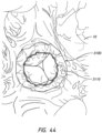
- Embodiments disclosed herein relate generally to prostheses for implantation within a lumen or body cavity.
- certain embodiments relate to expandable prostheses such as replacement heart valves, such as for the mitral valve, that are configured to be secured to intralumenal tissue and prevent paravalvular leakage.
- Human heart valves which include the aortic, pulmonary, mitral and tricuspid valves, function essentially as one-way valves operating in synchronization with the pumping heart.
- the valves allow blood to flow downstream, but block blood from flowing upstream.
- Diseased heart valves exhibit impairments such as narrowing of the valve or regurgitation, which inhibit the valves' ability to control blood flow.
- Such impairments reduce the heart's blood-pumping efficiency and can be a debilitating and life threatening condition.
- valve insufficiency can lead to conditions such as heart hypertrophy and dilation of the ventricle.
- extensive efforts have been made to develop methods and apparatuses to repair or replace impaired heart valves.
- Prostheses exist to correct problems associated with impaired heart valves.
- mechanical and tissue-based heart valve prostheses can be used to replace impaired native heart valves.
- substantial effort has been dedicated to developing replacement heart valves, particularly tissue-based replacement heart valves that can be delivered with less trauma to the patient than through open heart surgery.
- Replacement valves are being designed to be delivered through minimally invasive procedures and even percutaneous procedures.
- Such replacement valves often include a tissue-based valve body that is connected to an expandable frame that is then delivered to the native valve's annulus.
- Embodiments of the present disclosure are directed to a prosthesis, such as but not limited to a replacement heart valve.
- a prosthesis can be configured to be deployed within a body cavity and prevent axial flow of fluid around an exterior of the prosthesis.
- the prosthesis can include an expandable frame configured to radially expand and contract for deployment within the body cavity, and an annular skirt positioned around an exterior of the expandable frame.
- the prosthesis can further include a valve body configured to provide one-way flow through the prosthesis.
- the prosthesis can further include a plurality of anchors for securing the prosthesis to intraluminal tissue such as the native valve anatomy.
- Further embodiments are directed to methods of delivering a prosthesis, e.g. a replacement heart valve, and methods of using a prosthesis to create a barrier to fluid flow exterior to the prosthesis (e.g., to prevent paravalvular leakage).
- a prosthesis can include an expandable frame having a proximal end and a distal end and a longitudinal axis extending therethrough.
- the expandable frame can be configured to radially expand and contract for deployment within a native heart valve.
- the prosthesis can include a valve body positioned within an interior of the expandable frame.
- the valve body can include a plurality of leaflets each having an arcuate proximal edge and a free distal edge, the plurality of leaflets being joined at commissures.
- the plurality of leaflets can be configured to allow flow in a proximal-to-distal direction and prevent flow in a distal-to-proximal direction.
- the valve body can include one or more intermediate components connecting the leaflets to the expandable frame, wherein at least a portion of the arcuate proximal edge of each leaflet and/or the commissures are indirectly coupled to the expandable frame via the one or more intermediate components such that when the frame is in an expanded configuration, the one or more intermediate components position at least a portion of the arcuate proximal edge of each leaflet and/or the commissures radially inward from an inner surface of the frame.
- the one or more intermediate components can be formed from a material having a stiffness greater than that of the plurality of leaflets and less than that of the expandable frame. In some embodiments, the one or more intermediate components can be formed from a sheet of material. In some embodiments, the one or more intermediate components can be formed from a sheet of at least one of fabric, polyurethane, and polyethylene terephthalate (PET).
- PET polyethylene terephthalate
- the one or more intermediate components can include a first intermediate component and a second intermediate component.
- the first intermediate component can be tensioned in a first direction and the second intermediate component can be tensioned in a second direction when the frame is in an expanded configuration.
- the first direction can be oriented generally radially outwardly.
- the second direction can be oriented generally axially.
- the second direction can be oriented generally in a circumferential direction.
- the one or more intermediate components can include a third intermediate component. The first intermediate component, the second intermediate component, and the third intermediate component can form a pocket at or proximate a commissure of the valve body.
- the one or more intermediate components can include a cylindrical conduit. In some embodiments, at least one of the one or more intermediate components can extend in a radial direction between the expandable frame and the plurality of leaflets. In some embodiments, at least one of the one or more intermediate components can extend tangentially to the plurality of leaflets. In some embodiments, at least one of the one or more intermediate components extends in a direction generally aligned with the longitudinal axis of the frame. In some embodiments, at least one of the one or more intermediate components extends in circumferential direction. In some embodiments, the prosthesis can include an annular skirt extending around the exterior of the expandable frame.
- a proximal end of the annular skirt is attached to a proximal region of the expandable frame and a distal end of the annular skirt is attached to a distal region of the expandable frame.
- an intermediate region of the frame can have a diameter greater than a diameter of the proximal region and/or a diameter of the distal region.
- a prosthesis can include an expandable frame configured to radially expand and contract for deployment within a native heart valve.
- the expandable frame can include a proximal end and a distal end and a longitudinal axis extending therethrough.
- the expandable frame can include a supplemental prosthesis retention structure.
- the prosthesis can include a valve body positioned within an interior of the expandable frame.
- the valve body can include a plurality of leaflets configured to allow flow in a first direction and prevent flow in a second opposite direction.
- the supplemental prosthesis retention structure can include an interfacing structure.
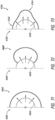
- the interfacing structure can include a plurality of V-shaped apices extending radially inward towards the longitudinal axis. The plurality of V-shaped apices can be configured to couple with a frame of a supplemental prosthesis.
- the supplemental prosthesis retention structure can include an interfacing structure.
- the interfacing structure can include a plurality of protrusions extending radially inwardly from distal portions of cells of the expandable frame.
- the supplemental prosthesis retention structure can include an internal expandable cage which can be configured to receive a supplemental prosthesis.
- the internal expandable cage can include a plurality of circumferentially-expansible struts.
- a prosthesis can include an expandable frame which can be configured to radially expand and contract for deployment within a native heart valve.
- the expandable frame can include a frame body which can include a proximal region, a distal region, an intermediate region extending between the proximal and distal regions, and a longitudinal axis extending between proximal and distal ends of the frame body.
- the frame body can include a plurality of struts forming one or more rows of cells.
- the proximal region can include a first bend adjacent the intermediate region. A proximally extending portion of the first bend can be inclined or curved towards the longitudinal axis.
- the distal region can include a second bend adjacent the intermediate region.
- a distally extending portion of the second bend can be inclined or curved towards the longitudinal axis.
- the intermediate region can have a generally cylindrical shape.
- a diameter of the intermediate region can be greater than a diameter of the proximal region and a diameter of the distal region.
- a height of the intermediate region can be greater than a height of the proximal region and a height of the distal region.
- the prosthesis can include a proximal anchoring feature attached to the frame body.
- the proximal anchoring feature can be sized to be positioned on a first side of an annulus of the native heart valve.
- the prosthesis can include a distal anchoring feature attached to the frame body.
- the distal anchoring feature can be sized to be positioned on a second side of an annulus of the native heart valve.
- the prosthesis can include a valve body positioned within an interior of the expandable frame, the valve body comprising a plurality of leaflets configured to allow flow in a first direction and prevent flow in a second opposite direction.
- the height of the distal region can be greater than the height of the proximal region.
- a ratio of a largest diameter of the frame body to the height of the frame body can be between about 3:1 to about 1:1.
- a ratio of a largest diameter of the frame body to the height of the frame body can be between about 2:1 to about 3:2.
- a ratio of the height of the intermediate region to the combined heights of the proximal region and the distal region can be between about 2:1 to about 1:2.
- a ratio of the height of the intermediate region to the combined heights of the proximal region and the distal region can be between about 3:2 to about 1:1. In some embodiments, when the expandable frame is in an expanded configuration, a ratio of a largest diameter of the frame body to a smallest diameter of the frame body can be between about 2:1 to about 4:3.
- the first bend when the expandable frame is in an expanded configuration, can orient a portion of the proximal region, positioned proximally of the beginning of the first bend, such that the portion forms an angle of between about 30 degrees to about 60 degrees with a plane orthogonal to the longitudinal axis. In some embodiments, when the expandable frame is in an expanded configuration, the first bend can orient a portion of the proximal region, positioned proximally of the beginning of the first bend, such that the portion forms an angle of between about 40 degrees to about 50 degrees with a plane orthogonal to the longitudinal axis.
- the second bend when the expandable frame is in an expanded configuration, can orient a portion of the distal region, positioned distally of the beginning of the second bend, such that the portion forms an angle of between about 30 degrees to about 60 degrees with a plane orthogonal to the longitudinal axis. In some embodiments, when the expandable frame is in an expanded configuration, the second bend can orient a portion of the distal region, positioned distally of the beginning of the second bend, such that the portion forms an angle of between about 40 degrees to about 50 degrees with a plane orthogonal to the longitudinal axis.
- the proximal anchoring feature can be attached to the proximal region of the frame body. In some embodiments, the proximal anchoring feature can include a plurality of anchors. In some embodiments, at least one of the anchors can include one or more eyelets. In some embodiments, at least one of the anchors can include two or more eyelets. In some embodiments, the distal anchoring feature can be attached to the distal region of the frame body. In some embodiments, the distal anchoring feature can include a plurality of distal anchors. In some embodiments, when the expandable frame is in an expanded configuration, at least one of the distal anchors can include ends extending radially outwardly away from the longitudinal axis.
- At least one of the distal anchors when the expandable frame is in an expanded configuration, can include ends extending radially outwardly away from the longitudinal axis in a direction generally perpendicular to the longitudinal axis. In some embodiments, when the expandable frame is in an expanded configuration, all of the distal anchors can include ends extending radially outwardly away from the longitudinal axis. In some embodiments, when the expandable frame is in an expanded configuration, at least one of the distal anchors can include ends extending radially inwardly towards the longitudinal axis.
- At least one of the distal anchors can include ends extending radially inwardly towards the longitudinal axis in a direction generally perpendicular to the longitudinal axis. In some embodiments, when the expandable frame is in an expanded configuration, all of the distal anchors can include ends extending radially inwardly towards the longitudinal axis.
- the expandable frame further can include a plurality of locking tabs.
- the locking tabs can include a bend in a direction opposite the first bend.
- the valve body further can include one or more intermediate components. At least a portion of each leaflet can be indirectly coupled to the expandable frame via the one or more intermediate components such that at least a portion of each leaflet is positioned radially inward from an inner surface of the frame body. In some embodiments, commissures of the valve body can be indirectly coupled to the expandable frame via the one or more intermediate components such that the commissures are positioned radially inward from the inner surface of the frame body. In some embodiments, at least a portion of an arcuate proximal edge of each leaflet can be indirectly coupled to the frame via the one or more intermediate components such that the arcuate proximal edge is positioned radially inward from the inner surface of the frame body. In some embodiments, at least a portion of an arcuate proximal edge of each leaflet can be directly coupled to the expandable frame.
- the one or more intermediate components can be formed from a material having a stiffness greater than that of the plurality of leaflets and less than that of the expandable frame.
- the one or more intermediate components can include a first intermediate component and a second intermediate component.
- the first intermediate component can be tensioned in a first direction and the second intermediate component can be tensioned in a second direction when the frame is in an expanded configuration.
- the first direction can be oriented generally radially outward.
- the second direction can be oriented generally axially.
- the second direction can be oriented generally in a circumferential direction.
- the one or more intermediate components can include a third intermediate component.
- the first intermediate component, the second intermediate component, and the third intermediate component can form a pocket at or proximate a commissure of the valve body.
- the one or more intermediate components can include a cylindrical conduit.
- at least one of the one or more intermediate components can extend in a radial direction between the expandable frame and the plurality of leaflets.
- at least one of the one or more intermediate components can extend tangentially to the plurality of leaflets.
- at least one of the one or more intermediate components can extend in a direction generally aligned with the longitudinal axis of the frame.
- at least one of the one or more intermediate components can extend in circumferential direction.
- the prosthesis can include an annular skirt extending around the exterior of the expandable frame.
- a proximal end of the annular skirt is attached to the proximal region of the frame body and a distal end of the annular skirt is attached to the distal region of the frame body.
- the prosthesis can include an expandable frame having a proximal end and a distal end and a longitudinal axis extending therethrough.
- the frame can be configured to radially expand and contract for deployment within a native heart valve.
- the prosthesis can include a valve body positioned within an interior of the expandable frame.
- the valve body can include a plurality of leaflets which can be configured to allow flow in a first direction and prevent flow in a second opposite direction.
- the prosthesis can include an annular skirt extending around the exterior of the expandable frame.
- the valve body can include one or more intermediate components.
- at least one of the valve body and the annular skirt can include one or more openings which can be configured to allow at least one of: fluid ingress into a space between the valve leaflets and the annular skirt, and fluid egress out of the space between the valve leaflets and the annular skirt.
- the one or more openings can be configured to allow fluid ingress into the space between the valve leaflets and the annular skirt when fluid flow is in the first direction.
- the one or more openings can be configured to allow fluid egress out of the space between the valve leaflets and the annular skirt when fluid flow is in the second direction.
- at least one of the one or more openings can be positioned within an area of the annular skirt between a first edge of a valve leaflet and the annular skirt.
- the prosthesis can include one or more conduits extending into the one or more openings.
- the expandable frame can include an anchoring member sized and shaped to be positioned on an inflow side of a native valve annulus.
- the one or more conduits can be configured to extend proximal of the anchoring member.
- the anchoring member can be positioned along a proximal portion of the expandable frame.
- the inflow side of the native valve annulus is an atrial side of the native mitral valve annulus.
- the annular skirt when the annular skirt is in an expanded configuration, the annular skirt comprises a supplemental rib extending from a portion of the annular skirt. In some embodiments, when the annular skirt is in an expanded configuration, a proximal portion of the annular skirt bulges radially outward relative to the distal portion of the annular skirt. In some embodiments, when the annular skirt is in an expanded configuration, a distal portion of the annular skirt bulges radially outward relative to the proximal portion of the annular skirt. In some embodiments, when the annular skirt is in an expanded configuration, the annular skirt extends around the entire circumferential periphery of the frame to a generally equivalent radial dimension. In some embodiments, the annular skirt extends to different radial dimensions with a first peripheral region extending to a first radial dimension and a second peripheral region extending to a second radial dimension greater than the first radial dimension.
- the prosthesis can include one or more biasing members which can be configured to bias the skirt into an expanded configuration.
- the one or more biasing members can include a radial spring.
- the one or more biasing members can include a cantilever.
- the annular skirt can be configured to transition into an expanded configuration via blood flow into the annular skirt.
- the prosthesis can include a one-way valve configured to allow blood flow into the annular skirt and inhibit blood flow out of the annular skirt.
- the one-way valve can be positioned on a valve skirt, the valve skirt being positioned between the plurality of leaflets and the annular skirt.
- the one-way valve can include a flap positioned on an exterior of the valve skirt.
- the one-way valve can include a duckbill valve.
- the one-way valve can be configured to allow blood flow into the annular skirt during systole and inhibit blood flow out of the annular skirt during diastole.
- the prosthesis can be a replacement mitral valve prosthesis, the expandable frame being configured for deployment within a native mitral valve.
- the prosthesis can include six distal anchors. In some embodiments, the prosthesis can include twelve distal anchors.
- the prosthesis can include an expandable frame which can be configured to radially expand and contract for deployment within a native heart valve.
- the expandable frame can include a frame body having a proximal region, a distal region, and an intermediate region extending between the proximal and distal regions.
- the frame body can include a first row of struts and a second row of struts.
- the expandable frame can include a supplemental frame having a first row of struts.
- the first row of struts can be configured to be generally aligned along the first row of struts of the frame body.
- the first row of struts of the supplemental frame can have a size and/or shape which generally matches the size and/or shape of the first row of struts of the frame body.
- the expandable frame can include a distal anchoring feature.
- the distal anchoring feature can be sized to be positioned on a first side of an annulus of the native heart valve.
- the distal anchoring feature can be positioned on a ventricular side of a native mitral valve annulus.
- the expandable frame can include a valve body positioned within an interior of the expandable frame.
- the valve body can include a plurality of leaflets which can be configured to allow flow in a first direction and prevent flow in a second opposite direction.
- the supplemental frame can be formed separately from the frame body.
- the first row of struts of the supplemental frame can be configured to be attached to at least a portion of the first row of struts of the frame body.
- the first row of struts of the supplemental frame can be attached to the first row of struts of the frame body via sutures.
- the first row of struts of the supplemental frame and the first row of struts of the frame body can have an undulating shape.
- the first row of struts of the supplemental frame can be configured to be positioned radially inwardly of the first row of struts of the frame body. In some embodiments, the first row of struts of the supplemental frame can be configured to be positioned radially outwardly of the first row of struts of the frame body.
- the distal anchoring feature can extend from the frame body. In some embodiments, the distal anchoring feature can extend distally from the frame body. In some embodiments, the distal anchoring feature can extend from the supplemental frame.
- the supplemental frame can include a second row of struts.
- the first and second rows of struts of the supplemental frame can form cells.
- the second row of struts of the supplemental frame can have an undulating shape.
- the second row of struts of the supplemental frame can be configured to extend distally of the frame body.
- the expandable frame can include a proximal anchoring feature.
- the proximal anchoring feature can be sized to be positioned on a second side of the annulus of the native heart valve.
- the proximal anchoring feature can be positioned on an atrial side of a native mitral valve annulus.
- the proximal anchoring feature can include a first row of struts.
- the first row of struts can be configured to be generally aligned along the second row of struts of the frame body.
- the first row of struts of the proximal anchoring feature can have a size and/or shape which generally matches the size and/or shape of the second row of struts of the frame body.
- the proximal anchoring feature can be formed separately from the frame body.
- the first row of struts of the proximal anchoring feature can be configured to be attached to at least a portion of the second row of struts of the frame body.
- the first row of struts of the proximal anchoring feature can be attached to the second row of struts of the frame body via sutures.
- the first row of struts of the proximal anchoring feature and the second row struts of cells of the frame body can have an undulating shape.
- the first row of struts of the proximal anchoring feature can be configured to be positioned radially outwardly of the second row of struts of the frame body. In some embodiments, the first row of struts of the proximal anchoring feature can be configured to be positioned radially inwardly of the second row of struts of the frame body. In some embodiments, the proximal anchoring feature can include a second row of struts. The first and second rows of struts of the proximal anchoring feature can form cells. In some embodiments, the second row of struts of the proximal anchoring feature can have an undulating shape.
- the second row of struts of the proximal anchoring feature can be configured to be generally aligned along a third row of struts of the frame body.
- the second row of struts of the proximal anchoring feature can have a size and/or shape which generally matches the size and/or shape of the third row of struts of the frame body.
- the prosthesis can include a plurality of locking tabs. In some embodiments, at least some of the locking tabs can extend from the frame body. In some embodiments, at least some of the locking tabs can extend from the frame body. In some embodiments, at least some of the locking tabs can extend from the frame body and at least some of the locking tabs can extend from the proximal anchoring feature.
- the locking tabs of the proximal anchoring feature can be configured to be generally aligned along the locking tabs of the frame body.
- the locking tabs of the proximal anchoring feature can have a size and/or shape which generally matches the size and/or shape of the locking tabs of the frame body.
- the distal anchoring feature can include a plurality of distal anchors, at least one of the distal anchors can include two or more prongs.
- the two or more prongs can be movable in a lateral direction relative to each other.
- a lateral dimension of the distal anchor having two or more prongs can increase when the expandable frame transitions to an expanded configuration.
- the two or more prongs can be movable in a radial direction relative to each other.
- a radial offset of the two or more prongs can increase when the expandable frame transitions to an expanded configuration.
- the distal anchoring feature includes one or more anchors configured to be movable in an axial direction relative to the frame body. In some embodiments, the distal anchoring feature includes one or more anchors having an insert. In some embodiments, the insert can be configured to extend radially outwardly relative to the frame body when the expandable frame is in an expanded configuration. In some embodiments, the insert can include a platform. The platform can be configured to extend radially and/or laterally outwardly relative to the distal anchor when the expandable frame is in an expanded configuration.
- At least one of the distal anchors can include a strut which bifurcates into two or more struts proximate a base of the distal anchor.
- the plurality of leaflets can each have an arcuate proximal edge and a free distal edge.
- the plurality of leaflets can be joined at commissures.
- the plurality of leaflets can be configured to allow flow in a proximal-to-distal direction and prevent flow in a distal-to-proximal direction.
- the valve body can include one or more intermediate components connecting the leaflets to the expandable frame.
- the one or more intermediate components can connect the leaflets to the expandable frame. At least a portion of the arcuate proximal edge of each leaflet and/or the commissures can be indirectly coupled to the expandable frame via the one or more intermediate components such that when the frame is in an expanded configuration, the one or more intermediate components position at least a portion of the arcuate proximal edge of each leaflet and/or the commissures radially inward from an inner surface of the expandable frame
- the one or more intermediate components can form a generally tangent surface with the expandable frame when the valve body is closed to prevent flow in the second direction. In some embodiments, the one or more intermediate components can form an angle between about 120° to about 195° with the expandable frame when the valve body is closed to prevent flow in the second direction. In some embodiments, the one or more intermediate components can form an angle between about 140° to about 190° with the expandable frame when the valve body is closed to prevent flow in the second direction. In some embodiments, the one or more intermediate components form an angle between about 160° to about 185° with the expandable frame when the valve body is closed to prevent flow in the second direction. In some embodiments, the one or more intermediate components can form an angle of about 180° with the expandable frame when the valve body is closed to prevent flow in the second direction.
- the prosthesis can include an annular skirt.
- the annular skirt can be at least partially formed from a material which can allow blood to flow therethrough.
- the material can be a partially porous cloth.
- the material can include one or more holes formed therethrough.
- the material can be configured such that, after deployment at the native heart valve, a rate of blood flow through the material decreases.
- the skirt can include a hydrogel which can reduce the rate of blood flow through the material.
- the present specification and drawings provide aspects and features of the disclosure in the context of several embodiments of prostheses, replacement heart valves, and methods that are configured for use in the vasculature of a patient, such as for replacement of natural heart valves in a patient. These embodiments may be discussed in connection with replacing specific valves such as the patient's mitral valve. However, it is to be understood that the features and concepts discussed herein can be applied to replacing other types of valves including, but not limited to, the aortic valve, the pulmonary valve, and the tricuspid valve. Moreover, it is to be understood that the features and concepts discussed herein can be applied to products other than heart valve implants.
- controlled positioning, deployment, and/or securing features described herein can be applied to medical implants, for example other types of expandable prostheses, for use elsewhere in the body, such as within a vein, or the like.
- particular features of a prosthesis should not be taken as limiting, and features of any one embodiment discussed herein can be combined with features of other embodiments as desired and when appropriate.
- proximal may refer to the parts of the prostheses, or components thereof, which are located closer to the operator of the device and system (e.g., the clinician implanting the prosthesis).
- distal may refer to the parts of the prostheses, or components thereof, which are located further from the operator of the device and system (e.g., the clinician implanting the prosthesis).
- this terminology may be reversed depending on the delivery technique utilized (e.g., a transapical approach as compared to a transseptal approach).
- prostheses 100, 200 are illustrated.
- the illustrated prostheses 100, 200 may include components which are self-expanding or balloon expandable.
- the prostheses 100, 200, as well as other prostheses described herein may be replacement valves that can be designed to replace a damaged or diseased native heart valve such as a mitral valve, as discussed above. It should be understood that the prostheses 100, 200, as well as other prostheses described herein, are not limited to being a replacement valve.
- the prosthesis 100 includes a frame 120, a valve body 140, and a skirt 160.
- the frame 120 can be self-expanding or balloon expandable.
- the frame 120 provides a structure to which various components of the prosthesis 100 can be attached.
- the frame 120 includes a frame body 122, a first anchoring feature 124, and a second anchoring feature 126.
- the frame body 122 includes an upper region 127, an intermediate region 128, and a lower region 129.
- the intermediate region 128 can have a larger diameter than the upper region 127 and/or the lower region 129.
- the frame 120 is oriented such that the upper region 127 is a proximal portion and the lower region 129 is a distal portion.
- the frame 120 can be formed from many different materials, including metals, such as Nitinol.
- the frame 120 is preferably formed from a plurality of struts forming open cells.
- components of the frame 120 such as the frame body 122, the first anchoring feature 124, and/or the second anchoring feature 126, can be used to attach or secure the prosthesis 100 to a native valve.
- the frame body 122 and the second anchoring feature 126 can be used to attach or secure the prosthesis 100 to a native valve, such as a native mitral valve.
- the frame 120 is sized to allow a supplemental prosthesis to be positioned within the frame 120.
- the frame 120 can include structural elements to secure the supplemental prosthesis to the frame 120. In some situations, this can allow for the use of a prosthesis designed for a different body cavity, such as a replacement aortic valve, to be positioned within the frame 120 when the frame 120 is positioned in another body cavity, such as a native mitral valve. However, it is to be understood that a prosthesis designed for the same body cavity can also be used. For example, in some situations, a supplemental prosthesis intended for the mitral valve can be used with the frame 120 when the frame 120 is positioned within the native mitral valve.
- the frame 120 can incorporate features and concepts which are the same as, or at least similar to, those of other frames described herein such as, but not limited to, frames 220, 300, 400, 500, 600, 700, 750, 810, 910, 1010, 1210, 1310, 1410, 1510, 1610, 1710, 1810, 1910, 2010, 2110, 2210, 2300, 2400, 2500, 2600, 2710, 2810, 2910, 3002, 3420, 3520, 3620, 3820, 3920, 4020, 4120, 4220, 4320, 4420, 4520, 4620, 4720, 4820, 4920, 5020, 5120, 5220, 6000, 6100, 6200, 6300, 6400, 6520, 6620, 6700, 6800, 6900, 7000, 7100 discussed below in connection with Figures 2-18 , 20- 43, 48-53, 58, 60-62, 64-80, 108-131.
- the frame 120 may include features and concepts similar to those disclosed in U.S. Patent Nos. 8,403,983, 8,414,644, and 8,652,203 and U.S. Publication Nos. 2010/0298931 , 2011/0313515 , 2014/0277390 , 2014/0277427 , 2014/0277422 , and 2015/0328000 , the entireties of each of which are hereby incorporated by reference and made a part of this specification. This is inclusive of the entire disclosure and is not in any way limited to the disclosure of the associated frames.
- the frame 120 has been described as including a frame body 122, a first anchoring feature 124, and a second anchoring feature 126, it is to be understood that the frame 120 need not include all components.
- the frame 120 can include the frame body 122 and the second anchoring feature 126 while omitting the first anchoring feature 124.
- the frame body 122, the first anchoring feature 124, and the second anchoring feature 126 have been illustrated as being unitarily or monolithically formed, it is to be understood that in some embodiments one or more of the frame body 122, the first anchoring feature 124, and the second anchoring feature 126 can be formed separately.
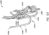
- the separate components can be attached using any of the fasteners and techniques described herein, such as via sutures as shown, for example, in Figures 120- 123.
- the first anchoring feature 124 and/or the second anchoring feature 126 can be formed separately from the frame body 122.
- the first anchoring feature 124 and/or the second anchoring feature 126 can be attached to the frame body 122 via sutures.
- the valve body 140 is attached to the frame 120 within an interior of the frame 120.
- the valve body 140 functions as a one-way valve to allow blood flow in a first direction through the valve body 140 and inhibit blood flow in a second direction through the valve body 140.
- the valve body 140 can allow blood flow in a proximal-to-distal direction and inhibit blood flow in a distal-to-proximal direction.
- the valve body 140 preferably includes a plurality of valve leaflets 142, for example three leaflets 142, which are joined at commissures.
- the valve body 140 can include one or more intermediate components 144.
- the intermediate components 144 can be positioned between a portion of, or the entirety of, the leaflets 142 and the frame 120 such that at least a portion of the leaflets 142 are coupled to the frame 120 via the intermediate component 144. In this manner, a portion of, or the entirety of, the portion of the valve leaflets 142 at the commissures and/or an arcuate edge of the valve leaflets 142 are not directly coupled or attached to the frame 120 and are indirectly coupled or "float" within the frame 120.
- valve leaflets 142 proximate the commissures and/or the arcuate edge of the valve leaflets 142 can be spaced radially inward from an inner surface of the frame 120.
- This can beneficially allow valve leaflets 142 having various shapes and sizes to be incorporated into a frame 120 having a shape and size which does not correspond to the shape and size of the valve leaflets 142.
- the valve leaflets 142 can be sized and shaped to form a generally cylindrical shape having a diameter.
- the valve leaflets 142 can be attached to non-cylindrical frames 120 and/or frames 120 having a diameter larger than that of the diameter of the valve leaflets 142.
- the one or more intermediate components 144 can also beneficially reduce stress concentrations on valve leaflets 142. This can advantageously increase the effective lifespan of the valve leaflets 142.
- the one or more intermediate components 144 can be formed from a material having a stiffness greater than that of the valve leaflet 142 yet less than that of the frame 120.
- valve body 140 can incorporate features and concepts similar to, or the same as, those of other valve bodies described herein such as, but not limited to, valve bodies 240, 820, 920, 1020, 1110, 1220, 1320, 1420, 1520, 1620, 1720, 1820, 1920, 2020, 2120, 2220, 2720, 2820, 2920, 3440, 3540, 3640, 4830, 6540, 6640, discussed below in connection with Figures 2-4 , 14-33 , 38-40 , 48-53 , 57 , 74 , 118, 120 , and 121.
- valve body 140 has been described as including a plurality of leaflets 142 and one or more intermediate components 144, it is to be understood that the valve body 140 need not include all features.
- the valve body 140 can include the plurality of valve leaflets 142 while omitting the intermediate components 144.
- the valve leaflets 142 can be directly attached to the frame 120.
- the skirt 160 can be attached to the frame 120.
- the skirt 160 can be positioned around and secured to an exterior of the frame 120.
- the skirt 160 can be annular and can extend entirely circumferentially around the frame 120.
- the skirt 160 can prevent or inhibit backflow of fluids, such as blood, around the prosthesis 100.
- the skirt 160 can create an axial barrier to fluid flow exterior to the frame 120 when deployed within a body cavity such as a native valve annulus.
- the skirt 160 can encourage tissue in-growth between the skirt 160 and the natural tissue of the body cavity. This may further help to prevent leakage of blood flow around the prosthesis 100 and can provide further securement of the prosthesis 100 to the body cavity.
- the skirt 160 can be loosely attached to the exterior of the frame 120.
- the skirt 160 can be tautly secured around the frame 120.
- skirt 160 can incorporate features and concepts similar to, or the same as, those of other skirts described herein such as, but not limited to, skirts 260, 2730, 2830, 2930, 3030, 3460, 3560, 3660, 3860, 3960, 4060, 4160, 4260, 4360, 4460, 4560, 4660, 4760, 4860, 4960, 5060, 5160, 6560, 6660 discussed below in connection with Figures 2-4 , 38-43 , 48-53 , 58-79 , 118 , 120 , and 121.
- the prosthesis 100 has been described as including a frame 120, a valve body 140, and a skirt 160, it is to be understood that the prosthesis 100 need not include all components.
- the prosthesis 100 can include only the frame 120 and the valve body 140 while omitting the skirt 160.
- the prosthesis 200 can include a frame 220, a valve body 240, and a skirt 260.
- the frame 220 can be self-expanding or balloon expandable.
- the frame 220 can include a frame body 222 formed from a plurality of struts defining a plurality of cells 224 (as shown in Figure 4 ).
- One or more of the cells 224 can allow the frame 220 to longitudinally foreshorten when the frame 220 radially expands.
- the frame 220 includes a first anchoring feature 226 and a second anchoring feature 228.
- the first anchoring feature 226 can be formed from a plurality of individual anchors extending from the frame body 222 in a direction radially outward from a longitudinal axis of the frame 220 and/or in a direction generally toward a lower end of the frame 220.
- the individual anchors of the first anchoring feature 226 can include tips or ends 230 having one or more eyelets. The eyelets can be used to facilitate attachment of a skirt, cover, and/or cushion to the first anchoring feature 226.
- the first anchoring feature 226 can include twelve individual anchors; however, it is to be understood that a greater number or lesser number of individual anchors can be used.
- the number of individual anchors can be chosen as a multiple of the number of commissures for the valve body 240.
- the first anchoring feature 226 can have three individual anchors, six individual anchors, nine individual anchors, twelve individual anchors, fifteen individual anchors, or any other multiple of three. It is to be understood that the number of individual anchors need not correspond to the number of commissures of the valve body 240.
- the second anchoring feature 228 can be formed from a plurality of individual anchors extending from the frame body 222 in a direction radially toward the longitudinal axis of the frame 220 and bent to extend in a direction radially outward from the longitudinal axis of the frame 220.
- a portion of the individual anchors, such as tips or ends 230, can extend in a direction generally toward an upper end of the frame 220.
- the individual anchors of the second anchoring feature 228 can include tips or ends 230 having covers and/or cushions as shown. In some embodiments, the tips or ends 230 can be enlarged relative to the preceding portion of the second anchoring feature 228, such as a strut.
- the covers and/or cushions can reduce pressure applied to tissue of the body cavity, such as the native valve annulus, when the tips or ends 230 contact the native valve annulus.
- the second anchoring feature 228 can include twelve individual anchors; however, it is to be understood that a greater number or lesser number of individual anchors can be used.
- the number of individual anchors can be chosen as a multiple of the number of commissures for the valve body 240.
- the second anchoring feature 228 can have three individual anchors, six individual anchors, nine individual anchors, twelve individual anchors, fifteen individual anchors, or any other multiple of three. It is to be understood that the number of individual anchors need not correspond to the number of commissures of the valve body 240.
- the frame 220 preferably includes a set of locking tabs 234 extending from the frame body 222 at its upper end. As shown, the frame 220 includes twelve locking tabs 234, however, it is to be understood that a greater number or lesser number of locking tabs can be used.
- the locking tabs 234 can extend generally upwardly from the frame body 222 in a direction generally aligned with the longitudinal axis of the frame 220.
- the locking tab 234 can include an enlarged head or end 236. As shown, the enlarged head or end 236 has a semi-circular or semi-elliptical shape forming a "mushroom" shape with the remaining portion of the locking tab 234.
- the locking tab 234 can include an eyelet which can be positioned through the enlarged head 236.
- the locking tab 234 can include an eyelet at other locations, or can include more than a single eyelet.
- the locking tab 234 can be advantageously used with multiple types of delivery systems such as a "slot-based" delivery system and/or a "tether-based" delivery system.
- the valve body 240 preferably includes a plurality of valve leaflets 242 each having a first edge 244, a second edge 246, and one or more tabs 248.
- the tabs 248 can form part of the valve leaflets 242 positioned at the commissures of the valve body 240.
- the second edge 246 can be a freely moving edge which can allow the valve body 240 to open and close.
- the valve leaflet 242 can be similar to leaflet 1110 illustrated in Figure 19A which includes a first edge 1112, a second edge 1114, and tabs 1116.
- the plurality of valve leaflets 242 can function in a manner similar to the native mitral valve, or to any other valves in the vascular system as desired.
- the valve body 240 can include one or more first intermediate components 250a (as shown in Figure 2 ) and one or more second intermediate component 250b (as shown in Figure 4 ).
- the one or more first intermediate components 250a and the one or more second intermediate components 250b can be used to attach one or more of the valve leaflets 242, or a portion thereof, to the frame 220 such that the valve leaflet 242 is indirectly coupled to the frame 220 or "floats" within the frame 220.
- at least a portion of the first edge 244 and the tabs 248 can be indirectly coupled to the frame 220 via the one or more intermediate components 250a, 250b with a portion of the first edge 244 directly coupled to the frame 220.
- the one or more first intermediate components 250a and/or one or more second intermediate components 250b can be formed from a combination of units, such as a combination of two, three, or more units. It is contemplated that the one or more intermediate components 250a, 250b can be formed from fewer units. As will be described in further detail, the intermediate components 250a, 250b can be attached to one or more third intermediate components to form a partially sealed or fully sealed pocket.
- the intermediate components 250 may be formed from a slightly porous material which allows fluid, such as blood, to enter into the pocket. In some instances, the blood can form a clot within the pocket.
- the skirt 260 can be loosely attached to the exterior of the frame 220.
- the skirt 260 can be formed from multiple components such as an upper component 262, a middle component 264, and a lower component 266.
- the upper component 262 can be attached to an upper portion of the frame 220. As shown, the upper component 262 can be attached at or proximate the uppermost cusp or first edge 244 of the valve leaflet 242.
- the upper component 262 can extend downwardly and be attached to the middle component 264.
- the middle component 264 can extend downwardly towards a lower portion of the frame 220.
- the middle component 264 can be attached at or proximate the commissures of the valve body 240 and/or the base of the anchors of the second anchoring feature 228.
- the lower component 266 can be attached to the middle component 264 and can extend downwardly. As shown, the lower edge of the lower component 266 can follow the undulations of the struts of the frame 220. However, it is contemplated that the lower component 266 can have a lower edge with a different shape, such as a straight edge.
- the skirt 260 can be formed from a greater number or lesser number of components. For example, one or more of the upper component 262, the middle component 264, and/or the lower component 266 can be combined into a single component.
- the skirt 260 can be formed from a variety of materials, such as a knit polyester (e.g., polyethylene terephthalate (PET)) or any other biocompatible material.
- PET polyethylene terephthalate
- the skirt 260 can be attached at or proximate the upper end of the frame 220 and at or proximate the lower end of the frame 220.
- the skirt 260 can be formed with sufficient material such that a portion of the skirt 260 positioned around a middle portion of the frame 220 is loose relative to an exterior of the frame 220.
- inventions of frames 300, 400, 500, 600, 700, and 750, 6000, 6100, 6200, 6300, 6400 and anchoring features 340, 350, 440, 450, 540, 550, 650, 710, 760, 5200, 5300, 5400, 5500, 5600, 5700, 5800, 5920, 5930, 6020, 6120, 6220, 6320, 6420 are illustrated.
- the frame 300 illustrated in Figure 5A the frame 300 is shown in an expanded configuration.
- the frame 300 can include a frame body 302 having an upper region 310, an intermediate region 320, and a lower region 330.
- a longitudinal axis of the frame 300 may be defined as the central axis that extends through the center of the frame 300 between the upper and lower ends of the frame 300.
- the frame 300 may be oriented such that the upper region 310 is a proximal portion and the lower region 330 is a distal portion.
- the frame 300 can include a first anchoring feature 340 and a second anchoring feature 350.
- the frame 300 may be oriented such that the first anchoring feature 340 is a proximal anchoring feature and the second anchoring feature 350 is a distal anchoring feature.
- One or both anchoring features 340, 350 can contact or engage a native valve annulus, such as the native mitral valve annulus, tissue beyond the native valve annulus, native leaflets, and/or other tissue at or around the implantation location during one or more phases of the cardiac cycle, such as systole and/or diastole.
- a native valve annulus such as the native mitral valve annulus, tissue beyond the native valve annulus, native leaflets, and/or other tissue at or around the implantation location during one or more phases of the cardiac cycle, such as systole and/or diastole.
- the second anchoring feature 350 is sized to contact or engage the native mitral valve annulus whereas the first anchoring feature 340 is sized to be spaced from the native mitral valve annulus. It is to be understood that in some embodiments, when the frame 300 is used for a replacement mitral valve prosthesis, during diastole and/or systole, in some embodiments both the first anchoring feature 340 and the second anchoring feature 350 are sized to contact or engage the native mitral valve annulus.
- the first anchoring feature 340 may contact a portion of a skirt, such as skirts 160, 260, which can contact or engage the native mitral valve annulus.
- the first anchoring feature 340 can be connected to a portion of a skirt.
- the anchoring features 340, 350 have been illustrated as extending from the upper and lower regions 310, 330 of the frame 300 respectively, it is to be understood that the anchoring features 340, 350 can be positioned along any other portion of the frame 300 as desired.
- two anchoring features 340, 350 have been included in the illustrated embodiment, it is to be understood that a greater number or lesser number of sets of anchoring features can be utilized.
- the frame body 302 when in an expanded configuration such as in a fully expanded configuration, has a bulbous or slightly bulbous shape, with an intermediate region 320 being larger than the upper region 310 and the lower region 330.
- the bulbous shape of the frame body 302 can advantageously allow the frame body 302 to engage a native valve annulus or other body cavity, while spacing the inlet and outlet from the heart or vessel wall. This can advantageously reduce undesired contact between the prosthesis and the heart or vessel, such as the atrial and ventricular walls of the heart.
- the intermediate region 320 is preferably cylindrical or generally cylindrical in shape such that a diameter of an upper end of the intermediate region 320 and/or a diameter of a lower end of the intermediate region 320 is equal or generally equal to the diameter of a middle portion of the intermediate region 320.
- the general uniformity of the diameter of the intermediate region 320 from the upper end to the lower end, in conjunction with the axial dimension between the upper end and the lower end i.e., the "height" of the intermediate region 320
- This can beneficially improve securement of the frame 300 to the native valve annulus or other body cavity.
- frame body 302 such as the intermediate portion 302
- the frame body 302 has been described and illustrated as being cylindrical, it is to be understood that all or a portion of the frame body 302 can be have a non-circular cross-section such as, but not limited to, a D-shape, an oval or an otherwise ovoid cross-sectional shape.
- the diameter of the upper end of the intermediate region 320 and the lower end of the intermediate region 320 can be about the same. However, it is to be understood that the diameter of the upper end of the intermediate region 320 and the lower end of the intermediate region 320 can differ.
- the frame body 302 in an expanded configuration can have a diameter at its widest portion of between about 30mm to about 60mm, between about 35mm to about 55mm, about 40mm, any sub-range within these ranges, or any other diameter as desired. In some embodiments, the frame body 302 in an expanded configuration has a diameter at its narrowest portion between about 20mm to about 40mm, any sub-range within these ranges, or any other diameter as desired.
- the ratio of the diameter of the frame body 302 at its widest portion to the diameter of the frame body 302 at its narrowest portion can be about 3:1, about 5:2, about 2:1, about 3:2, about 4:3, any ratio within these ratios, or any other ratio as desired.
- the frame body 302 preferably has an axial dimension between the upper and lower ends of the frame body 302 (i.e., the "height" of the frame body 302) of between about 10mm to about 40mm, between about 18mm to about 30mm, about 20mm, any sub-range within these ranges, or any other height as desired.
- the frame body 302 can have an axially compact configuration relative to the radial dimension.
- the ratio of the diameter of the largest portion of the frame body 302 to the height of the frame body 302 when the frame is in its expanded configuration can be about 3:1, about 5:2, about 2:1, about 3:2, about 4:3, about 13:10, about 5:4, or about 1:1.
- the width at the largest portion of the frame body 302 can be greater than the height of the frame body 302.
- the height of the intermediate region 320 can be larger than the axial dimension between the upper and lower ends of the upper region 310 (i.e., the "height" of the upper region 310) and/or the axial dimension between the upper and lower ends of the lower region 330 (i.e., the "height" of the lower region 330).
- the height of the upper region 310 is preferably between about 3mm to about 10mm.
- the height of the intermediate region 320 can be between about 6mm to about 15mm.
- the height of the lower region 330 can be between about 3mm to about 15mm.
- the ratio of the height of the intermediate region 320 to the combined heights of the upper region 310 and lower region 330 can be about 1:2, about 2:3, about 3:5, about 1:1, about 5:3, about 3:2, about 2:1, any ratio within these ratios, or any other ratio as desired.
- the height of the intermediate region 320 can be greater than the height of the lower region 330 and the height of the lower region 330 can be greater than the height of the upper region 310.
- the frame body 302 can include a bend 312.
- the bend 312 can be a radially inward bend towards the longitudinal axis of the frame 300 such that a portion of the upper region 310, extending upwardly from the beginning of bend 312 adjacent the intermediate region 320, is inclined or curved towards the longitudinal axis of the frame 300.
- the radially inward inclination of the upper region 310 can allow for a substantial decrease in radial dimension over a relatively small axial dimension. The greater the degree of inclination, the greater the decrease in radial dimension per increase in axial dimension. This can beneficially provide a relatively compact or "squat" form factor for the frame body 302.
- the inclined or curved portion of the upper region 310 can facilitate the securement of a supplemental prosthesis within frame 300.
- the bend 312 can orient the portion of the upper region 310, positioned upward of the beginning of bend 312, such that it forms an angle of between about 20 degrees to about 70 degrees with a plane orthogonal to the longitudinal axis of the frame 300, an angle of between about 30 degrees to about 60 degrees with a plane orthogonal to the longitudinal axis of the frame 300, an angle of between about 40 degrees to about 50 degrees with a plane orthogonal to the longitudinal axis of the frame 300, an angle of about 45 degrees with a plane orthogonal to the longitudinal axis of the frame 300, any subrange within these ranges, or any other angle as desired.
- an angle of about 40 degrees to about 50 degrees can allow for a significant reduction in radial dimension per increase in axial dimension while still reducing strain when the frame 300 is in a crimped configuration.
- the bend 312 can orient the portion of the upper region 310, positioned upward of the beginning of bend 312, such that it forms an angle of less than 70 degrees with a plane orthogonal to the longitudinal axis of the frame 300, an angle of less than 55 degrees with a plane orthogonal to the longitudinal axis of the frame 300, an angle of less than 40 degrees with a plane orthogonal to the longitudinal axis of the frame 300, an angle of less than 25 degrees with a plane orthogonal to the longitudinal axis of the frame 300, or less than any other angle as desired.
- the bend 312 can generally form an arc with an angle between about 20 degrees to about 90 degrees.
- the arc can have an angle of about 45 degrees.
- the bend 312 can form an arc with an angle between about 30 degrees to about 60 degrees.
- the radius of curvature of the arc may be constant such that the bend 312 forms a circular arc or may differ along the length of the bend 312.
- the frame body 302 can include a bend 332 toward the longitudinal axis of the frame 300.
- the bend 332 can be a radially inward bend towards the longitudinal axis of the frame 300 such that a portion of the lower region 330, extending downwardly from the beginning of bend 332 adjacent the intermediate region 320, is inclined or curved towards the longitudinal axis of the frame 300.
- the radially inward inclination of the lower region 330 can allow for a substantial decrease in radial dimension over a relatively small axial dimension. The greater the degree of inclination, the greater the decrease in radial dimension per increase in axial dimension.
- the bend 332 can orient the portion of the lower region 330, positioned below the beginning of bend 332, such that it forms an angle of between about 20 degrees to about 70 degrees with a plane orthogonal to the longitudinal axis, an angle of between about 30 degrees to about 60 degrees with a plane orthogonal to the longitudinal axis, an angle of between about 40 degrees to about 50 degrees with a plane orthogonal to the longitudinal axis, an angle of about 45 degrees with a plane orthogonal to the longitudinal axis, any subrange within these ranges, or any other angle as desired.
- An angle of about 40 degrees to about 50 degrees can allow for a significant reduction in radial dimension per increase in axial dimension while still reducing strain when the frame 300 is in a crimped configuration.
- the bend 332 can orient the portion of the lower region 330, positioned below of the beginning of bend 332, such that it forms an angle of less than 70 degrees with a plane orthogonal to the longitudinal axis, an angle of less than 55 degrees with a plane orthogonal to the longitudinal axis, an angle of less than 40 degrees with a plane orthogonal to the longitudinal axis, an angle of less than 25 degrees with a plane orthogonal to the longitudinal axis, or less than any other angle as desired.
- the bend 332 can generally form an arc with an angle between about 20 degrees to about 90 degrees.
- the arc can have an angle of about 45 degrees.
- the bend 332 can form an arc with an angle between about 30 degrees to about 60 degrees.
- the radius of curvature of the arc may be constant such that the bend 332 forms a circular arc or may differ along the length of the bend 332.
- the lower region 330 can include a bend 334 below the bend 332.
- the bend 334 can be oriented opposite that of the bend 332 such that a portion of the lower region 330, extending downwardly from the beginning of the bend 334, is inclined or curved at less of an angle towards the longitudinal axis of the frame 300 than the portion above the beginning of bend 334, is generally parallel to the longitudinal axis, or is inclined or curved at an angle away from the longitudinal axis of the frame 300. This can beneficially reduce the rate of decrease in radial dimension over the remainder of the axial dimension of the lower region 330.
- the bend 334 can orient the portion of the lower region 330, positioned below the beginning of bend 334, such that it forms an angle of between about 30 degrees to about 90 degrees with a plane orthogonal to the longitudinal axis, an angle of between about 45 degrees to about 85 degrees with a plane orthogonal to the longitudinal axis, an angle of between about 60 degrees to about 80 degrees with a plane orthogonal to the longitudinal axis, an angle of about 80 degrees with a plane orthogonal to the longitudinal axis, any subrange within these ranges, or any other angle as desired.
- the bend 334 can orient the portion of the lower region 330, positioned below the beginning of bend 334, such that it forms an angle of greater than 25 degrees with a plane orthogonal to the longitudinal axis, an angle of greater than 40 degrees with a plane orthogonal to the longitudinal axis, an angle of greater than 55 degrees with a plane orthogonal to the longitudinal axis, an angle of greater than 70 degrees with a plane orthogonal to the longitudinal axis, or greater than any other angle as desired.
- the diameter of the upper end of the upper region 310 and the lower end of the lower region 330 can be about the same. However, it should be understood that the diameter of the upper end of the upper region 310 and the lower end of the lower region 330 can differ. Moreover, in some embodiments, the frame body 302 may not have a bulbous portion, and can have substantially the same outer dimension along its entire length (e.g., cylindrical), or it may have one end larger than the other end. For example, the intermediate region 320 and the lower region 330 can have the same, or substantially the same, diameter.
- the frame body 302 can include a plurality of struts with at least some of the struts forming cells 360a, 360b, 360c. Any number of configurations of struts can be used, such as rings of undulating struts shown forming ellipses, ovals, rounded polygons, and teardrops, but also chevrons, diamonds, curves, and various other shapes. As shown in the illustrated embodiment, the frame body 302 can include three rows of cells 360a, 360b, 360c.
- the upper row of cells 360a can have a hexagonal or generally hexagonal shape.
- the cell 360a can be formed via a combination of struts.
- the upper portion of cells 360a can be formed from a set of circumferentially-expansible struts 365 having a zig-zag or undulating shape forming a repeating "V" shape.
- the circumferentially-expansible struts 365 can be inclined or curved towards a longitudinal axis of the frame 300 such that an upper portion of the struts 365 are positioned closer to the longitudinal axis of the frame 300 than the lower portion of the struts 365.
- the middle portion of cells 360a can be formed from a set of struts 370 extending downwardly from bottom ends of each of the "V" shapes.
- the struts 370 can extend generally longitudinally in a distal direction.
- the struts 370 can incorporate the bend 312 such that an upper portion of the struts 370 are inclined or curved towards the longitudinal axis of the frame 300 and the lower portion of the struts 370 extend in a direction generally parallel to the longitudinal axis of the frame 300.
- the lower portion of cells 360a can be formed from a set of circumferentially-expansible struts 375 having a zig-zag or undulating shape forming a repeating "V" shape.
- circumferentially-expansible struts 375 can form a generally cylindrical portion of the frame 300 with the upper portion of the struts 375 having a radial dimension which is about the same as the radial dimension as the lower portion of the struts 375.
- the portion of the cells 360a extending upwardly from the bottom end of struts 370 may be considered to be a substantially non-foreshortening portion of the frame 300.
- foreshortening refers to the ability of the frame to longitudinally shorten as the frame radially expands.
- the cells 360a can have an irregular hexagon shape.
- hexagonal cells 360a can be symmetrical about a vertical axis extending from upper to lower ends of the cell 360a.
- two of the sides of the hexagonal cells 360a can be one length, while the other four sides of the cells 360a can be a greater length.
- the two sides with the same length can be generally parallel to one another.
- the middle and/or lower rows of cells 360b, 360c can have a different shape from the cells 360a of the first row.
- the middle and lower row of cells 360b, 360c can have a diamond or generally diamond shape.
- the cells 360b, 360c may be considered to be a substantially foreshortening portion of the frame 300.
- the diamond or generally diamond shape can be formed via a combination of struts.
- the upper portion of cells 360b can be formed from the set of circumferentially-expansible struts 375 such that cells 360b share struts with cells 360a.
- the lower portion of cells 360b can be formed from a set of circumferentially-expansible struts 380.
- circumferentially-expansible struts 380 can extend generally in a downward direction.
- the circumferentially-expansible struts 380 can incorporate the bend 332 such that an upper portion of the struts 380 form a generally cylindrical portion of the frame 300 and the lower portion of the struts 380 can be inclined or curved towards the longitudinal axis of the frame 300.
- the upper portion of cells 360c can be formed from the set of circumferentially-expansible struts 380 such that cells 360c share struts with cells 360b.
- the lower portion of cells 360c can be formed from a set of circumferentially-expansible struts 385.
- Circumferentially-expansible struts 385 can extend generally in a downward direction.
- the circumferentially-expansible struts 385 can be inclined or curved towards the longitudinal axis of the frame 300.
- the angle of inclination of the circumferentially-expansible struts 385 can be different from the angle of inclination of the lower portion of circumferentially-expansible struts 380.
- the circumferentially-expansible struts 385 can be less inclined or curved towards the longitudinal axis of the frame 300 than the lower portion of circumferentially-expansible struts 380.
- the angle of inclination of circumferentially-expansible struts 385 can be chosen based on the supplemental prosthesis the frame 300 is designed to receive.
- the cells 360a, 360b, 360c were described as generally hexagonal-shaped and generally diamond-shaped, it is to be understood that some or all of the struts 365, 370, 375, 380, 385 may not form entirely straight segments.
- the struts 365, 370, 375, 380, 385 can include some curvature such that the upper and/or lower apices are curved.
- the struts 375, 380 forming apices of cells 360b can incorporate curvature such that the apices are generally "onion" shaped.
- the number of cells 360a, 360b, 360c can correspond to the number of anchors or anchor tips forming the first anchoring feature and/or the number of anchors or anchor tips forming the second anchoring feature.
- the number of cells in each row of cells 360a, 360b, 360c have a 1:1 correspondence with the number of anchors in both the first anchoring feature 340 and the second anchoring feature 350 (i.e., twelve cells in each row of cells 360a, 360b, 360c and twelve anchors for the anchoring features 340, 350). It is to be understood that other ratios of numbers of cells per row to number of anchors per anchoring feature can be used such as, but not limited to, 2:1, 3:1, 4:1, 5:1, 6: 1, and other ratios as desired. For example, as shown in the embodiment of frame 300 illustrated in Figure 5B , the number of cells in some rows may be increased to a 2:1 ratio with anchors of one or both of the anchoring features, such as anchoring feature 350'.
- anchors of anchoring feature 350' illustrated in Figure 5B are equally spaced with two cells between each anchor, it is to be understood that the anchors can be unequally spaced. In some implementations, two anchors may be spaced apart by one cell whereas the remaining anchors are spaced apart by two or more cells. As another example, as shown in the embodiment of frame 600 illustrated in Figure 9 , the number of cells in some rows may be increased to a 2:1 ratio.
- the geometry of cells 360a, 360b, 360c can allow the cells 360a, 360b, 360c to foreshorten as the frame 300 is expanded.
- one or more of cells 360a, 360b, 360c can allow the frame 300 to foreshorten as the frame 300 is expanded.
- Foreshortening of the frame 300 can be used to secure the prosthesis to intralumenal tissue in a body cavity, for example tissue at or adjacent a native valve, such as a native valve annulus and/or leaflets.
- the anchoring features 340, 350 and anchor tips 344, 358 are preferably located along the frame 300 with at least part of the foreshortening portion positioned between the anchoring features 340, 350 so that a portion of the anchoring features 340, 350 will move closer together with expansion of the frame 300.
- this can allow the anchoring features 340, 350 to close in on opposite sides of the native mitral annulus to thereby secure the prosthesis at the mitral valve.
- the anchoring features 340, 350 can be positioned such that the anchoring features 340, 350 do not contact opposing portions of the native mitral annulus at the same time.
- the anchoring feature 350 may contact the native mitral annulus while the anchoring feature 340 does not contact the native mitral annulus. This can be beneficial when anchoring feature 340 are used to provide stabilization and help align the prosthesis.
- the anchoring features 340, 350 can be positioned such that the anchoring features 340, 350 grasp opposite side of the native mitral annulus.
- anchoring feature 340 can include one or more anchors.
- the anchoring feature 340 can include twelve anchors.
- Each anchor can include one or more struts 342 extending from an upper region 310 of the frame body 302.
- struts 342 extend into the cells 360a.
- the struts 342 extend from an upper intersection of two segments of the cell 360a, for example, from the uppermost corner of the cells 360a between struts 365.
- the struts 342 can extend from other portions of the frame body 302, such as other portions of the cell 360a.
- the struts 342 extend generally downwardly into the cells 360a while curving outwards away from the frame body 302.
- the anchoring feature 340 extends radially outwardly from the frame body 302 as it extends generally downwardly towards a tip 344.
- the tips 344 of the anchoring feature 340 can end after extending approximately between about one-third to about two-thirds of the height of hexagonal cells 360a when the frame 300 is expanded. Further, the tips 344 can extend farther outwards than the frame body 302.
- the anchoring feature 340 can include one or more eyelets such as the two eyelets illustrated per strut 342.
- the one or more eyelets can form a portion of the tip 344 of the anchoring feature 340.
- the one or more eyelets can be used to attach other components of the prosthesis in which the frame 300 is used, such as a skirt.
- the shape of the one or more eyelets beneficially reduce the potential for trauma should the tips 344 contact tissue such as that of the native valve annulus or other body cavity.
- Anchoring feature 350 can include one or more anchors.
- the anchoring feature 350 can include twelve anchors.
- the anchoring feature 350' can include a fewer or greater number of anchors.
- the anchoring feature 350 can include six anchors.
- Each anchor can include one or more struts 352 extending from a lower region 330 of the frame 300. As shown, struts 352 extend from a lower intersection of two segments of the cell 360b, for example, from the lowermost corner of the cells 360b between struts 380.
- the struts 352 can extend from other portions of the frame 300, such as other portions of the cell 360b and/or other portions of the cells 360c.
- the struts 352 can extend from a lower intersection of two segments of the cell 360c, for example, from the lowermost corner of the cells 360c between struts 385.
- the struts 352 extend generally downwardly while curving inwardly towards the longitudinal axis from the frame 300.
- the narrowest portion of the anchoring feature 340 can have a diameter which is about the same as, or less than, a diameter of the lower region 330 of the frame body 302.
- the struts 352 can incorporate a bend 354 to orient the strut 352 such that it extends radially outward away from the longitudinal axis of the frame 300.
- the bend can be generally semi-circular or semi-elliptical which can provide a space for the distal ends of the native valve leaflets to be stored.
- the anchors may then extend in a linear segment radially outwardly and upwardly.
- the struts 352 can include a second bend 356 along the linear segment. As shown in the illustrated embodiment, the bend 356 can orient the strut 352 such that it extends generally parallel to the longitudinal axis of the frame 300.
- the tip 358 of anchoring feature 350 can extend generally parallel to the longitudinal axis of the frame 300.
- the tips 358 of the anchoring feature 350 can end after extending approximately above the base or connection point of the anchoring feature 350 to the frame body 302. In some embodiments, the tips 358 of the anchoring feature 350 can end after extending up to, or slightly past, the lower end of the intermediate region 320 of the frame body 302.
- the bend 356 orients the tip 358 such that it extends generally parallel to a longitudinal axis of the frame 300
- the bend 356 can orient the struts 352, such as the tips 358, in other directions.
- the bend 356 can orient the struts 352, such as the tips 358, such that the they extend radially outward away from the longitudinal axis of the frame 300, such that struts 352 extends radially inward towards the longitudinal axis of the frame 300, or such that a portion of struts 352 extends radially outward away from the longitudinal axis of the frame 300 and another portion of struts 352.
- the bend 356 can orient the struts 352, such as the tips 358, such that they extend generally perpendicular to a longitudinal axis of the frame 302 such as is shown with frame 400 illustrated in Figure 6 .
- the tips or ends 344, 358 as described above can advantageously provide atraumatic surfaces that may be used to contact or engage intralumenal tissue without causing unnecessary or undesired trauma to tissue.
- the tips or ends 344, 358 can form flat, substantially flat, curved or other non-sharp surfaces to allow the tips to engage and/or grasp tissue, without necessarily piercing or puncturing through tissue.
- a looped end or looped anchor may assist the frame in not getting caught up on structures at or near the treatment location.
- each loop can be configured so that when the frame 300 is deployed in-situ and the anchoring features 340, 350 expand away from the frame body 302, the movement of each loop from a delivered position to a deployed position avoids getting caught on the papillary muscles.
- the first anchoring feature 340 includes rounded eyelets at a tip or end 344 of the anchoring feature 340.
- the second anchoring feature 350 includes anchors tips or ends 358 having looped ends with a flattened or rounded top surface.
- the anchors of the first anchoring feature 340 can be circumferentially staggered with respect to the anchors of the second anchoring feature 350 meaning that the tips or ends 344 of the first anchoring feature 340 are not aligned, circumferentially, with the tips or ends 358 of the second anchoring feature 350.
- the anchors of the first anchoring feature 340 and the anchors of the second anchoring feature 358 can be circumferentially aligned.
- each of the anchoring features 340, 350 are positioned or extend generally radially outwardly from the frame 300 so that the anchor tips 344, 358 are generally spaced away or radially outward from the rest of the frame body 302 and from where the base of the anchors connect to the frame body 302.
- the anchor tips 344, 358 may be located radially outward from the intermediate region 320 of the frame body 302, with the tips 344, 358 being axially spaced from one another.
- At least some of the anchoring features can extend to a radial distance from an exterior surface of the intermediate region 320 of the frame body 302 that is about 110% or more of the expanded diameter of the intermediate region 320 of the body 302 at the plane of tips 344, 358.
- all of the anchors of the first anchoring feature 340 and/or all of the anchors of the second anchoring feature 350 extend at least to this radial distance. In other embodiments, fewer than all of the anchors of the first anchoring feature 340 and/or all of the anchors of the second anchoring feature 350 extend to this radial distance.
- the outermost diameter of the first anchoring feature 340 and/or the second anchoring feature 350 may be greater than the diameter of frame the body 302 as described above and may be in the range of about 35mm to about 70mm when expanded, in the range of about 35mm to about 60mm when expanded, in the range of about 40mm to about 60mm when expanded, in the range of about 45mm to about 50mm when expanded, any sub-range within these ranges when expanded, or any other diameter as desired.
- the first anchoring feature 340 and the second anchoring feature 350 can extend radially outward from the longitudinal axis of the frame 300 to about the same radial dimension. However, it is to be understood that in other embodiments (not shown), the first anchoring feature 340 can be positioned to be not as far radially outward as the second anchoring feature 350 or the second anchoring feature 350 can be positioned to be not as far radially outward as the first anchoring feature 340. Such configurations may be advantageous in positioning and securing the prosthesis in a native valve annulus or other body location.
- the anchoring features 340, 350 can have various other configurations.
- the frame 300 includes anchoring features 340, 350 with twelve anchors each, it is to be understood that a greater number of anchors or a lesser number of anchors can be used.
- the number of anchors can correspond to the number of commissures of the internal valve used with the frame 300.
- the number of anchors can be chosen in multiples of three such as three anchors, six anchors, twelve anchors, fifteen anchors, and any other multiple of three.
- first anchoring feature 340 instead of a 1:1 correspondence between the number of anchors in the first anchoring feature 340 and the second anchoring feature 350 (i.e., twelve anchors each), other ratios can be used. For example, a 1:2 or a 1:3 correspondence between the anchors, are possible such that the first anchoring feature 340 or the second anchoring feature 350 have fewer anchors than the other anchoring feature.
- Individual anchors may extend radially outwardly from the frame at an anchor base and terminate at an anchor tip.
- the individual anchors can be connected to the frame at one of many different locations including apices, junctions, other parts of struts, etc.
- the anchors forming the anchoring features 340, 350 can comprise first, second, third, or more spaced apart bending stages along the length of each anchor. Further details that may be incorporated and/or interchanged with the features described herein are disclosed in U.S. Publication Nos. 2014/0277422 , 2014/0277427 , 2014/0277390 , and 2015/0328000 , which have been incorporated by reference herein.
- Covers and/or cushions may be used to surround or partially surround at least a portion of the first anchoring feature 340 and/or the second anchoring feature 350, such as the tips or ends 344 of the first anchoring feature 340 and/or the tips or ends 358 of the second anchoring feature 350 and/or the struts to which the tips or ends 344, 458 are attached.
- the covers and/or cushions can be similar to those described in U.S. Publication No. 2015/0328000 , which has been incorporated by reference in its entirety.
- the covers and/or cushions can be formed from one or more pieces of material.
- an inner portion can be positioned within a covering such that the covering forms a layer surrounding the inner portion.
- the inner portion can be formed of a foam material, such as a polymer foam, such that the inner portion is at least somewhat compliant.
- the covering can be formed of a biocompatible, fabric material such as a polymer woven or knitted cloth or sheet.
- the cushions can be formed as a polymer molded insert.
- the covers and/or cushions can be taut.
- the covers and/or cushions can be loosely coupled to the anchoring feature. For example, a loosely coupled cover can be positioned along a side of a strut intended to be positioned against tissue.
- the covers and/or cushions can either fit snuggly around the tips 358 or can have extra padding so that the covers extend radially away from the frame 300.
- all of the anchors of the second anchoring feature 350 can have the covers and/or cushions with some of the anchors having less cushioning than others.
- all of the anchors of the second anchoring feature 350 can have the padded covers.
- all of the anchors of the second anchoring feature 350 can have the snuggly fitting cushions.
- not all of all of the anchors of the second anchoring feature 350 can have covers.
- the frame 300 can include a set of locking tabs 390 extending from the upper region 310 of the frame 300. As shown, the frame 300 includes twelve locking tabs 390, however, it is to be understood that a greater number or lesser number of locking tabs can be used.
- the locking tabs 390 can extend generally upwardly from the upper region 310 in a direction generally aligned with the longitudinal axis of the frame 300.
- the locking tabs 390 include a strut 392 which can include a bend 394 such that a portion of the strut 392, positioned upwards of the beginning of the bend 394, is inclined or curved at less of an angle towards the longitudinal axis of the frame 300 than the portion below the beginning of the bend 394, is generally parallel to the longitudinal axis, or is inclined or curved at an angle away from the longitudinal axis of the frame 300.
- the bend 394 can orient the portion of the strut 392, positioned upward of the beginning of bend 394, such that it forms an angle of between about 30 degrees to about 90 degrees with a plane orthogonal to the longitudinal axis, an angle of between about 45 degrees to about 85 degrees with a plane orthogonal to the longitudinal axis, an angle of between about 60 degrees to about 80 degrees with a plane orthogonal to the longitudinal axis, an angle of about 80 degrees with a plane orthogonal to the longitudinal axis, any subrange within these ranges, or any other angle as desired.
- the bend 394 can orient the portion of the strut 392, positioned upward of the beginning of bend 394, such that it forms an angle of greater than 25 degrees with a plane orthogonal to the longitudinal axis, an angle of greater than 40 degrees with a plane orthogonal to the longitudinal axis, an angle of greater than 55 degrees with a plane orthogonal to the longitudinal axis, an angle of greater than 70 degrees with a plane orthogonal to the longitudinal axis, or greater than any other angle as desired.
- the locking tab 390 can include an enlarged head 394.
- the enlarged head 394 has a semi-circular or semi-elliptical shape forming a "mushroom" shape with the strut 396.
- the locking tab 390 can include an eyelet 396 which can be positioned through the enlarged head 394. It is to be understood that the locking tab 234 can include an eyelet at other locations, or can include more than a single eyelet.
- the locking tab 390 can be advantageously used with multiple types of delivery systems. For example, the shape of the struts 392 and the enlarged head 394 can be used to secure the frame 300 to a "slot" based delivery system.
- the eyelets 396 can be used to secure the frame 300 to a "tether" based delivery system such as those which utilize sutures, wires, or fingers to control delivery of the frame 300. This can advantageously facilitate recapture and repositioning of the frame 300 in situ.
- the frame 300 can be used with the delivery systems described in U.S. Patent Nos. 8,414,644 and 8,652,203 and U.S. Publication Nos. 2015/0238315 , the entireties of each of which are hereby incorporated by reference and made a part of this specification.
- the frame 400 can include a frame body 402 having an upper region 410, an intermediate region 420, and a lower region 430.
- a longitudinal axis of the frame 400 may be defined as the central axis that extends through the center of the frame 400 between the upper and lower ends of the frame 400.
- the frame 400 may be oriented such that the upper region 410 is a proximal portion and the lower region 430 is a distal portion.
- the frame 400 can include a first anchoring feature 440 and a second anchoring feature 450.
- the frame 400 may be oriented such that the first anchoring feature 440 is a proximal anchoring feature and the second anchoring feature 450 is a distal anchoring feature.
- the height of the intermediate region 420 can be larger relative to the heights of the upper region 410 and lower region 430 as compared to the height of the intermediate region 320 relative to the heights of the upper region 310 and lower region 330.
- This can advantageously provide a larger circumferential area upon which a native valve annulus can be engaged.
- This can also beneficially enhance securement of the frame 400 to the native valve annulus or other body cavity.
- this can beneficially reduce the overall height of the frame 400.
- the frame 400 can include a bend 432 toward the longitudinal axis of the frame 400.
- the bend 432 can be a radially inward bend towards the longitudinal axis of the frame 400 such that a portion of the lower region 430, extending downwardly from the beginning of bend 432, is inclined or curved towards the longitudinal axis of the frame 400.
- the lower region 430 can include a second bend 434 below the bend 432.
- the bend 434 can be oriented opposite that of the bend 432 such that a portion of the lower region 430, extending downwardly from the beginning of the bend 434, is inclined or curved at an angle away from the longitudinal axis of the frame 400. This can beneficially allow at least a portion of the lower region 430 to form part of the second anchoring feature 450.
- the frame 400 can include a first row of cells 460a, a second row of cells 460b, and a third row of cells 460c (as shown in Figure 7 ) which can share some similarities to cells 360a, 360b, 360c of frame 300.
- the upper portion of cells 460c can be formed from the set of circumferentially-expansible struts 480 such that cells 460c share struts with the cells of the row above.
- the lower portion of cells 460c can be formed from a set of circumferentially-expansible struts 485.
- Circumferentially-expansible struts 485 can extend generally in a downward direction.
- the circumferentially-expansible struts 485 can be inclined or curved away from the longitudinal axis of the frame 400 such that the upper portion of struts 485 are positioned closer to the longitudinal axis of the frame 400 than the lower portion of struts 485.
- the bend 434 can be formed by struts 485 and can be shaped similarly to the bend 354 discussed in connection with struts 352 of the second anchoring feature 350 of frame 300.
- Anchoring feature 450 can include one or more anchors.
- the anchoring feature 450 can include twelve anchors.
- Each anchor can include one or more struts 452 extending from a lower region 430 of the frame 400.
- struts 452 extend from a lower intersection of two segments of the cell 360c, for example, from the lowermost corner of the cells 460c between struts 485.
- the struts 452 can extend from other portions of the frame 400, such as other portions of the cell 460b and/or other portions of the cells 460c.
- the struts 452 can extend from a lower intersection of two segments of the cell 460b, for example, from the lowermost corner of the cells 460c between struts 480.
- the struts 452 extend generally radially outward.
- the struts 452 can incorporate a bend 454 to orient the strut 452 such that it extends radially outward away from the longitudinal axis of the frame 400 and upwards.
- the anchors may then extend in a linear segment radially outwardly and upwardly.
- the struts 452 can include a second bend 456 along the linear segment. As shown in the illustrated embodiment, the bend 456 can orient the strut 452 such that it extends generally radially outward from the longitudinal axis of the frame 400 and generally perpendicular to the longitudinal axis of the frame 400.
- the tip 458 of anchoring feature 450 can extend generally perpendicular to the longitudinal axis of the frame 400. This can beneficially increase the tissue contact area of the tip 458 of the anchor as compared to an anchor which does not incorporate such a bend. This increased tissue contact area can beneficially reduce the stress applied by the tip 458 to tissue thereby reducing the amount of pressure and potential for trauma to the tissue.
- the uppermost portions of the anchoring feature 450 can extend up to, or slightly past, the lower end of the intermediate region 420 of the frame body 402.
- the frame 400 can include locking tabs 490.
- These locking tabs 490 are similar to locking tabs 390 of frame 300; however, the locking tabs 490 have a lower axial dimension thereby providing for a more compact form factor.
- the locking tabs 490 do not include eyelets, it is to be understood that the locking tabs 490 can include eyelets.
- the frame 400 is shown as a flat pattern.
- Any of the frames described herein such as, but not limited to, frames 300, 400 can be made of many different materials, but is preferably made from metal.
- the frames can be made from a shape memory material, such as nitinol.
- a wire frame or a metal tube can be used to make the frame.
- the wire frame of a metal tube can be cut or etched to remove all but the desired metal skeleton.
- a metal tube is laser cut in a repeating pattern to form the frame.
- the flat pattern can be cut from a metal tube and then the tube can be bent and expanded to the expanded configurations shown herein.
- the frames can further be expanded and/or compressed and/or otherwise worked to have the desired shape or shapes, such as for introduction and implantation.
- the frame 500 is shown as a flat pattern.
- the frame 500 can include first anchoring feature 540, second anchoring feature 550, a first row of cells 560a, a second row of cells 560b, a third row of cells 560c, and a plurality of locking tabs 590.
- the second anchoring feature 550 can include anchors with tips 558 having one or more eyelets.
- each anchor can include two eyelets. The eyelets can beneficially facilitate attachment of other components, such as covers and/or cushions, to the tips 558.
- the frame 600 can include a frame portion 602 having an upper region 610, an intermediate region 620, and a lower region 630.
- a longitudinal axis of the frame 600 may be defined as the central axis that extends through the center of the frame 600 between the upper and lower ends of the frame 600.
- the frame 600 may be oriented such that the upper region 610 is a proximal portion and the lower region 630 is a distal portion.
- the frame 600 can include an anchoring feature 650.
- the frame 600 may be oriented such that the anchoring feature 650 is a distal anchoring feature.
- anchoring feature 650 can include one or more anchors.
- the anchoring feature 650 can include nine anchors each including a strut 652 extending from a lower region 630 of the frame body 602.
- the diameter of the frame body 602 at the widest portion is approximately the same as those of frames 300, 400, 500 are their widest portions.
- the overall length of the frame 600 can be similar to those of frames 300, 400, 500 when in a collapsed configuration for delivery. As shown in the illustrated embodiment, this can be achieved via strut and cell geometry.
- cells 660a there can be a first row of nine cells 660a, a second row of eighteen cells 660b, a third row of eighteen cells 660c, and a row of nine cells 660d.
- Cells 660b share similarities to cells 360a, 460a, 560a.
- cells 660b can have a hexagonal or generally hexagonal shape.
- Cells 660 have generally longitudinally extending struts 670 which can extend generally parallel to the longitudinal axis of the frame 600.
- Cells 660a, 660c share similarities to cells 360b, 460b, 560b.
- cells 660a, 660c can have a diamond or generally diamond shape.
- Cells 660d have an irregular polygonal shape.
- the number of cells in the first row of cells 660a and fourth row of cells 660d correspond to the number of anchors of the anchoring portion 650.
- the number of cells in the second row of cells 660b and the third row of cells 660c are twice that of the number of anchors. This can beneficially allow the frame to reach a desired width while maintaining a relatively axially compact profile when crimped into a collapsed configuration.
- Other ratios of the number of cells to the number of anchors can be chosen including 3:1, 4:1, 5: 1, or any other ratio as desired.
- the frame 700 includes anchoring feature 710 having covers and/or cushions 720.
- the anchoring feature 710 can have a similar profile to those of anchoring feature 350.
- the anchoring feature 710 can include a cover and/or cushion 720 extending over a tip 712 of the anchors.
- the cover and/or cushion 720 can be positioned such that it extends over the top of the tip 712.
- the cover and/or cushion 720 can also be positioned such that it extends circumferentially around the tip 712.
- the cover and/or cushion 720 can be formed from a deformable material such as a foam.
- cover and/or cushion 720 When the top portion of the cover and/or cushion 720 is subject to pressure due to a downwardly directed force, the cover and/or cushion 720 can compress and expand laterally outward. Such a force may be exerted upon the cover and/or cushion 720 when the cover and/or cushion 720, for example, when the cover and/or cushion 720 contacts a ventricular side of the mitral valve annulus during systole.
- the compression and lateral expansion of cover and/or cushion 720 can increase the surface area of the cover and/or cushion 720 in contact with the tissue, thereby exerting less pressure on the tissue and reducing the potential for trauma.
- the frame 750 includes anchoring feature 760 having covers and/or cushions 770.
- the anchoring feature 760 can have a tip profile similar to that of anchoring feature 450.
- the anchoring feature 760 can include a cover and/or cushion 770 extending over a tip 762 of the anchors.
- the cover and/or cushion 770 can be positioned such that it extends over the top of the tip 762.
- the cover and/or cushion 770 can also be positioned such that it extends circumferentially around the tip 762.
- the cover and/or cushion 770 can be formed from a deformable material such as a foam.
- cover and/or cushion 770 When the top portion of the cover and/or cushion 770 is subject to pressure due to a downwardly directed force, the cover and/or cushion 770 can compress and expand laterally outward. Such a force may be exerted upon the cover and/or cushion 770 when the cover and/or cushion 770, for example, when the cover and/or cushion 770 contacts a ventricular side of the mitral valve annulus during systole.
- the compression and lateral expansion of cover and/or cushion 770 can increase the surface area of the cover and/or cushion 770 in contact with the tissue, thereby exerting less pressure on the tissue and reducing the potential for trauma.
- the anchoring features 5200, 5300 can include one or more prongs which are at least radially offset relative to each other.
- tips of the one or more prongs can be at different radial positions relative to a longitudinal axis of a frame (not shown) to which the anchoring features 5200, 5300 are attached.
- This can beneficially increase the tissue contact area of the tips of the anchoring features 5200, 5300.
- This increased tissue contact area can beneficially reduce the stress applied by the anchoring features 5200, 5300 to tissue thereby reducing the amount of pressure and potential for trauma to the tissue.
- the radial distance between the prongs of the anchoring features 5200, 5300 can be reduced or eliminated when in a collapsed configuration. This can beneficially reduce the crimp profile of the anchoring features 5200, 5300 such that a smaller delivery system can be utilized.
- anchoring feature 5200 is illustrated.
- the anchoring feature 5200 can be attached to a frame body (not shown) via one or more struts 5210.
- the anchoring feature 5200 can include one or more prongs 5220, 5230 having tips 5222, 5232.
- the first prong 5220 can form a loop similar to other anchoring features described herein.
- the second prong 5230 can be positioned within the first prong 5230. Positioning the second prong 5230 within the first prong 5220 can advantageously make use of an existing space within the first prong 5220.
- the first prong 5220 and the second prong 5320 can be radially offset.
- the first prong 5220 can include a bend 5224 which directs the first prong 5220 radially outward relative to the second prong 5230 such that the tips 5222, 5232 are at different radial positions relative to each other.
- One or more coverings and/or cushions can be attached to the anchoring feature 5200 which covers the tips 5222, 5232.
- the one or more coverings and/or cushions can span the gap between the tips 5222, 5232 to further increase the tissue contact area of the tips.
- the coverings and/or cushions can include the same or similar structure to those described herein.
- the coverings and/or cushions can be formed from a foam material, woven or knitted cloth or sheet, and/or an insert.
- the tip 5222 of prong 5220 can be extend in a direction generally parallel to tip 5232 of prong 5230. While the tips 5222, 5232 are shown at or around the same axial position, it is to be understood that the tips 5222, 5232 can be axially offset.
- the prong 5230 can include an eyelet 5234.
- anchoring feature 5300 is illustrated.
- the anchoring feature 5300 can be attached to a frame body (not shown) via one or more struts 5310.
- the anchoring feature 5300 can include one or more prongs 5320, 5330, 5340 having tips 5222, 5232, 5342.
- the first prong 5320, the second prong 5320, and/or the third prong 5340 can be radially offset.
- the first prong 5320 can include a bend 5224 which directs the first prong 5320 radially outward relative to the second prong 5330 such that the tips 5322, 5332 are at different radial positions relative to each other.
- the third prong 5340 can include a bend 5344 which directs the third prong 5340 radially inward relative to the second prong 5330 such that the tips 5342, 5332 are at different radial positions relative to each other.
- One or more coverings and/or cushions (not shown) can be attached to the anchoring feature 5300 which covers the tips 5322, 5332, 5342.
- the one or more coverings and/or cushions can span the gap between the tips 5222, 5232, 5342 to further increase the tissue contact area of the tips.
- the coverings and/or cushions can include the same or similar structure to those described herein.
- the coverings and/or cushions can be formed from a foam material, woven or knitted cloth or sheet, and/or an insert. While the tips 5322, 5332, 5342 are shown at or around the same axial position, it is to be understood that the tips 5322, 5332, 5342 can be axially offset.
- anchoring features 5400, 5500, 5600, 5700 can transition between a crimped or collapsed configuration and an expanded configuration.
- the anchoring features 5400, 5500, 5600, 5700 can have a reduced crimp profile to facilitate delivery to a target location.
- the anchoring features 5400, 5500, 5600, 5700 can increase in size which can advantageously increase the tissue contact area of the anchoring features 5400, 5500, 5600, 5700. This increased tissue contact area can beneficially reduce the stress applied by the anchoring features 5400, 5500, 5600, 5700 to tissue thereby reducing the amount of pressure and potential for trauma to the tissue.
- anchoring feature 5400 is illustrated.
- the anchoring feature 5400 can transition between a collapsed configuration (as shown in Figures 86 and 87 ) and an expanded configuration (as shown in Figures 88- 90 ).
- the lateral dimension (or width) of the anchoring feature 5400 can increase.
- the anchoring feature 5400 can be attached to a frame body (not shown) via one or more struts 5410.
- the anchoring feature 5400 can include one or more prongs 5420, 5430 having tips 5422, 5432.
- the anchoring feature 5400 can have a looped profile similar to other anchoring features described herein.
- the first prong 5420 and the second prong 5430 can be radially offset such that the tip 5422 of first prong 5420 is radially outward relative to the tip 5432 of the second prong 5430. This can allow the tips 5422, 5432 to slide relative to each other when transitioning between the collapsed configuration and the expanded configuration.
- the tips 5422, 5432 can form a relatively flat surface of the anchoring feature 5400 ; however, it is to be understood that the tips 5422, 5432 can take on a more rounded shape similar to other anchoring features described herein. Moreover, while the tips 5422, 5432 are shown at or around the same axial position, it is to be understood that the tips 5422, 5432 can be axially offset. One or more cushions (not shown) can be attached to the anchoring feature 5400 which cover the tips 5422, 5432.
- anchoring feature 5500 is illustrated.
- the anchoring feature 5500 can transition between a collapsed configuration (as shown in Figure 91 ) and an expanded configuration (as shown in Figure 92 ). In transitioning from the collapsed configuration to the expanded configuration, the lateral dimension (or width) of the anchoring feature 5500 can increase.
- the anchoring feature 5500 can be attached to a frame body (not shown) via one or more struts 5510.
- the anchoring feature 5500 can include one or more prongs 5520, 5530 having tips 5522, 5532.
- the first prong 5520 and the second prong 5530 can be laterally offset such that a gap exists between tips 5522, 5532 of the prongs 5520, 5530.
- One or more coverings and/or cushions (not shown) can be attached to the anchoring feature 5500 which cover the tips 5522, 5532.
- the one or more coverings and/or cushions can span the gap between the tips 5522, 5532 to further increase the tissue contact area of the tips.
- the coverings and/or cushions can include the same or similar structure to those described herein.
- the coverings and/or cushions can be formed from a foam material, woven or knitted cloth or sheet, and/or an insert. While the tips 5522, 5532 are shown at or around the same axial position, it is to be understood that the tips 5522, 5532 can be axially offset.
- anchoring feature 5600 is illustrated.
- the anchoring feature 5600 can transition between a collapsed configuration (as shown in Figure 93 ) and an expanded configuration (as shown in Figure 94 ). In transitioning from the collapsed configuration to the expanded configuration, the lateral dimension (or width) of the anchoring feature 5600 can increase.
- the anchoring feature 5600 can be attached to a frame body (not shown) via one or more struts 5610.
- the anchoring feature 5600 can include one or more prongs 5620, 5630 having tips 5622, 5632.
- the anchoring feature 5600 can have a generally looped profile similar to other anchoring features described herein.
- the first prong 5620 and the second prong 5630 can be axially offset such that the tip 5622 of first prong 5620 is positioned above tip 5632 of the second prong 5630. This can allow the tips 5622, 5632 to slide relative to each other when transitioning between the collapsed configuration and the expanded configuration.
- the tips 5622, 5432 can be at or around the same radial position.
- One or more coverings and/or cushions can be attached to the anchoring feature 5600 which cover the tips 5622, 5632.
- the one or more coverings and/or cushions can span the axial offset between the tips 5622, 5632 to further increase the tissue contact area of the anchoring feature 5600.
- the coverings and/or cushions can include the same or similar structure to those described herein.
- the coverings and/or cushions can be formed from a foam material, woven or knitted cloth or sheet, and/or an insert.
- anchoring feature 5700 is illustrated.
- the anchoring feature 5700 can transition between a collapsed configuration (as shown in Figures 95 and 96 ) and an expanded configuration (as shown in Figures 97- 99 ).
- the lateral dimension (or width) and/or a radial offset of the anchoring feature 5700 can increase.
- the anchoring feature 5700 can be attached to a frame body (not shown) via one or more struts 5710.
- the anchoring feature 5700 can include one or more prongs 5720, 5730 having tips 5722, 5732.
- the tips 5722, 5732 can form an enlarged, looped shape.
- the enlarged looped shape can reduce the likelihood that the tips 5722, 5732 are improperly aligned prior to crimping.
- the enlarged loop shape can reduce the likelihood that the tips 5722, 5732 are in the same radial plane prior to crimping. It is to be understood that the tips 5722, 5732 can form other shapes such as those described in connection with other anchoring features described herein.
- the first prong 5720 and the second prong 5730 can be radially offset such that the tip 5722 of first prong 5720 is radially outward relative to the tip 5732 of the second prong 5730. This can allow the tips 5722, 5732 to slide relative to each other when transitioning between the collapsed configuration and the expanded configuration. As shown, the tips 5722, 5732 can form a relatively flat surface of the anchoring feature 5700; however, it is to be understood that the tips 5722, 5732 can take on a more rounded shape similar to other anchoring features described herein.
- the tips 5722, 5732 are shown at or around the same axial position, it is to be understood that the tips 5722, 5732 can be axially offset.
- One or more coverings and/or cushions (not shown) can be attached to the anchoring feature 5700 which cover the tips 5722, 5732.
- the one or more coverings and/or cushions can span the radial offset and/or lateral offset between the tips 5722, 5732 to further increase the tissue contact area of the anchoring feature 5700.
- the coverings and/or cushions can include the same or similar structure to those described herein.
- the coverings and/or cushions can be formed from a foam material, woven or knitted cloth or sheet, and/or an insert.
- the anchoring feature 5800 can include a base anchor 5810 to which one or more additional components, such as inserts 5820, can be attached.
- the insert 5820 can extend radially outward relative to the base anchor 5810 when the frame (not shown) is in an expanded configuration; however, it is to be understood that the insert 5820 can extend in other directions relative to the base anchor 5810.
- the insert 5820 can extend in directions including, but not limited to, radially inward, laterally, and/or axially relative to the base anchor 5810.
- the base anchor 5810 can be attached to a frame body (not shown) of the replacement valve.
- the base anchor 5810 can be unitarily formed with the frame body similar to other anchoring features described herein.
- the base anchor 5810 can be unitarily formed with the frame body via laser-cutting a single tube.
- the insert 5820 can be formed separately from the base anchor 5810 and attached using any of the fasteners and techniques described herein, such as via sutures, welding, adhesives, and/or a snap-fit, such as via connectors 5826, 5828 described below. As will be described in further detail below, the insert 5820 can increase the tissue contact area of the anchoring feature 5800.
- the anchoring feature 5800 can be attached to a frame body via one or more struts 5812 of the base anchor 5810.
- the base anchor 5810 can include a strut forming a portion of the tip 5830 of the anchoring feature 5800.
- the tip 5830 can have a looped shape which forms a hole or aperture 5816.
- the insert 5820 can be positioned at least partially within the hole or aperture 5816.
- the insert 5820 can include a rib 5822 and a platform 5824.
- the insert 5820 may also include one or more connectors 5826, 5828.
- the rib 5822 can extend generally axially and radially when the insert 5820 is attached to the base anchor 5810.
- the rib 5822 can beneficially support other portions of the insert 5820 at least when the insert 5820 is subject to an axial load.
- the rib 5822 can have an arcuate shape when viewed from a side profile. The arcuate shape can reduce the likelihood of the rib 5822 catching onto to native anatomy, such as chordae tendineae when the anchoring feature 5800 is positioned at a target location.
- the platform 5824 can form a contact surface for native anatomy, such as a ventricular side of the native mitral valve annulus. As shown, the platform 5824 can extend laterally outward relative to the base anchor 5810 and/or the rib 5822. The platform 5824 can form a generally planar surface. By increasing the lateral extent of the platform 5824, the tissue contact area of the anchoring feature 5800 can be significantly increased. This increased tissue contact area can beneficially reduce the stress applied by the anchoring feature 5800 to tissue thereby reducing the amount of pressure and potential for trauma to the tissue.
- the insert 5820 can include one or more connectors 5826, 5828.
- the connectors 5826, 5828 can be used to facilitate coupling of the insert 5820 to the base anchor 5810.
- the one or more connectors 5826, 5828 can snap fit into openings of the base anchor 5810.
- one or more complementary openings can be formed along the strut within the hole or aperture 5816 of the base anchor 5810.
- the one or more connectors 5826, 5828 can extend across the hole or aperture 5816 and clamp onto an opposite side of the base anchor 5810.
- the one or more connectors 5826, 5828 can be omitted.
- the base anchor 5810 can be formed from a relatively rigid material and the insert 5820 can be formed from another material which may be more compliant than the material used for the base anchor 5810. This can increase the strength of the base anchor 5810 to allow the base anchor 5810 to resist loads imposed on the anchoring feature 5800 while in use.
- the compliancy of the insert 5820 can better conform to the native anatomy to enhance the tissue contact area and reduce the potential for trauma to tissue of the native anatomy.
- the base anchor 5810 can be formed from a metal, such as nitinol, and the insert 5820 can be formed from a softer metal or plastic.
- the insert 5820 can have a cushion-like structure similar to other cushions described herein.
- the insert 5820 can be formed at least partially from a foam material. This can beneficially enhance the compliancy of the insert 5820 and allow the insert 5820 to better conform to native anatomy.
- at least the platform 5824 is formed from a foam material.
- at least the insert 5820 can be formed from a material that facilitates tissue ingrowth or formation. This can further enhance securement of the anchoring feature 5800 to tissue of the native anatomy.
- the base anchor 5810 and the insert 5820 can be formed from the same material. Use of separate components can facilitate manufacture of the anchoring feature 5800. As noted above, the base anchor 5810 can be unitarily formed with the frame body via laser-cutting a single tube. In such an embodiment, it may be difficult or impossible to form the geometry of the insert 5820. As such, the insert 5820 can be manufactured via an alternative manufacturing method.
- the delivery system 5900 can include an outer sheath 5910 and an inner sheath or rail 5912.
- Two anchoring features 5920, 5930 are illustrated within the outer sheath 5910 in a crimped or collapsed configuration.
- two anchoring features 5920, 5930 are shown, it is to be understood that a fewer or greater number of anchoring features can be used.
- two different anchoring features 5920, 5930 are illustrated, it is to be understood that the anchoring features can be the same.
- Anchoring feature 5920 can share structures similar to anchoring feature 5800 described above.
- the anchoring feature 5920 can include a base anchor 5922 and an insert 5924.
- the insert 5924 of the anchoring feature 5920 extends radially inward relative to the base anchor 5922. This can more efficiently utilize the available space between the outer sheath 5910 and the inner sheath 5912.
- the anchoring feature 5920 can flip around in a manner similar to other anchoring features described herein. In so doing, the insert 5924 can be positioned radially outward relative to the base anchor 5920 similar to anchoring feature 5800.
- Anchoring feature 5930 can share structures similar to anchoring features 5400, 5700 described above.
- the anchoring feature 5930 can include a first prong 5932 and a second prong 5934 which are radially offset relative to each other.
- the first prong 5932 of the anchoring feature 5930 is positioned radially outward of the second prong 5934 and is wider than the second prong 5934. This can more efficiently utilize the available space between the outer sheath 5910 and the inner sheath 5912.
- the frame 6000 can include a frame body 6010 having one or more struts forming cells 6012.
- the frame 6000 can include an anchoring feature 6020 having a strut 6022 and a tip 6024.
- the tip 6024 can form a looped shape; however, it is to be understood that the tip 6024 can incorporate any other tip configuration described herein.
- the strut 6022 can split into two or more struts 6026a, 6026b proximate a base or pivot location 6028 between the frame body 6010 and the anchoring feature 6020.
- the strut 6022 can bifurcate into two struts 6026a, 6026b which are each connected to struts 6014a, 6014b forming part of cells 6012.
- the struts 6014a, 6026a can be disconnected from struts 6014b, 6026b such that the struts 6014a, 6026a are movable relative to struts 6014b, 6026b.
- This configuration can beneficially reduce strains imposed on the struts 6014a, 6014b, 6026a, 6026b when the frame 6000 is in a collapsed or crimped configuration and/or when the frame 6000 is subject to fatigue loading.
- the struts can effectively widen the outflow struts to allow for a greater distribution of strain during crimping and/or during fatigue loading since the struts are separated into two individual members.
- the aspect ratio of the anchoring feature 6020 proximate the base or pivot location 6028 is larger than the aspect ratio of the anchoring feature 6020 further distal of the base or pivot location 6028. This can beneficially reduce resistance to side-loading and/or out-of-plane loading.
- localized stresses at the pivot location 6028 can be sufficient to effect at least a partial phase transformation of the material at the pivot location 6028.
- localized stresses can be sufficient to cause at least partial "martensitic transformation" of nitinol at the pivot location 6028.
- This "martensitic transformation” can transform nitinol into the martensite phase from the austenite phase which has different material properties than the austentite phase. For example, nitinol in the austenite phase is less malleable and does not exhibit the same level of elastic deformation characteristics as nitinol in the martensite phase.
- the frames 6100, 6200 can include anchoring features 6120, 6220 with anchors having different lengths. This can allow the anchors to have different heights when the frames 6100, 6200 are in an expanded configuration. This can be particularly advantageous in situations where the native anatomy is non-planar.
- the native mitral valve typically has a non-planar, saddle-shape.
- the frame 6100 can include a frame body 6110 having one or more struts 6012 forming cells (not shown).
- the frame 6100 can include an anchoring feature 6120 in the form of multiple individual anchors 6122a-e. As shown in the illustrated embodiment, the individual anchors 6122a-e can have different lengths. The lengths can be chosen based on the contemplated position of the individual anchors 6122a-e on the native valve anatomy.
- short anchors such as anchor 6122b can be positioned at an anterior or posterior location of the native mitral valve (e.g., the A2 and P2 lobes as shown in Figure 109B ) whereas longer anchors such as anchor 6122e can be positioned at or proximate commissures of the native mitral valve (e.g., the A1, A3, P1, or P3 lobes as shown in Figure 109B ).
- the strength and/or compliancy of individual anchors 6122a-e can differ.
- primary, load-bearing anchors can be stiffer than other anchors. These primary, load-bearing anchors can be designed to engage stiffer tissue at anterior or posterior locations of the native mitral valve.
- two primary anchors can be positioned behind the native anterior leaflet. Two or three primary anchors can be positioned behind the native posterior leaflet. This can beneficially enhance securement to the native annulus.
- primary anchors can be positioned at the A1 and A3 lobes of the native anterior leaflet 6130 and/or the P1, P2, and P3 lobes of the native posterior leaflet 6140 (as shown in Figure 109B ). Moreover, this can beneficially increase the likelihood that at least one anchor extends behind the leaflets. Although four to five primary anchors have been described, it is to be understood that a fewer or greater number of primary anchors can be used. For example, in some embodiments, two to six primary anchors can be utilized.
- Secondary anchors can be more compliant than other anchors. These secondary anchors can interact with more compliant tissue. In some implementations, these secondary anchors can be sized and shaped to isolate and/or immobilize the free edge of a native leaflet. This can beneficially reduce movement of the native leaflet during the cardiac cycle which can, in some instances, advantageously improve tissue ingrowth and/or reduction of paravalvular leakage. In some implementations, secondary anchors can be positioned at the A2 lobe of the native anterior leaflet 6130 and/or the commissures of the native mitral valve. The number of secondary anchors can be chosen to obtain a total number of desired anchors. For example, in embodiments having twelve anchors, the frame 6100 can have five primary anchors and seven secondary anchors. It is to be understood that a fewer or greater number of total anchors may be used as described above (e.g., nine total anchors).
- the frame 6200 can include a frame body 6210 having one or more struts forming cells 6212.
- the frame 6200 can include an anchoring feature 6220 having one or more anchors 6222a, 6222b.
- the individual anchors 6222a, 6222b can be adjustable to different heights. The heights can be changed based on the positioning of the individual anchors 6222a, 6222b relative to the native valve anatomy such as the native mitral valve annulus 6230. Individual placement of anchors can advantageously provide the user more controlled deployment of individual anchors.
- a slight tug by the operator can be applied after each individual anchor is placed to verify that the anchor is well placed before moving onto the next anchor.
- individual anchors can be more suitably positioned relative to the native valve anatomy. This can advantageously reduce the likelihood that the frame 6200 tilts or rocks during the various cardiac cycles of the patient's heart. Among other benefits, this can reduce the likelihood of paravalvular leakage which may be caused by tilting or rocking of the frame 6200.
- one or more of the anchors can be attached to the frame body 6210 via one or more connector tabs 6214, 6216, 6218.
- the connector tabs 6214, 6216, 6218 can include apertures through which a strut 6224b of the anchor 6222b can be passed.
- a first connector tab 6214 can be positioned along a bottom region of a cell 6212.
- the first connector tab 6214 can be positioned at or proximate a bottom apex of the cell 6212.
- a second connector tab 6216 can be positioned along a top region of a cell 6212.
- the second connector tab 6216 can be positioned at or proximate a top apex of the cell 6212.
- a third connector tab 6218 can be positioned between the first and second connector tabs 6214, 6216.
- the connector tabs 6214, 6216, 6218 can be sized and shaped to retain the anchor 6222b in position.
- the connector tabs 6216, 6218 can be biased in a direction which is non-perpendicular to a longitudinal axis of the frame body 6210.
- the connector tabs 6216, 6218 can impose a frictional force on the strut 6224b which can resist translation of the strut 6224b relative to the connector tabs 6216, 6218. This frictional force is preferably sufficient to resist axially directed forces exerted on the anchor 6222b.
- the connector tabs 6216, 6218 can allow the anchor 6222b to move axially in one direction (e.g., proximally) while inhibiting or preventing movement in the opposite direction (e.g., distally). For example, this can allow the operator to pull on the anchor 6222b in a proximal direction to shorten the anchor 6222b while inhibiting the anchor 6222b from moving distally and elongating during operation in the patient's heart.
- the connector tabs 6216, 6218 can be pinched or squeezed towards each other to reduce this frictional force thereby facilitating adjustment of the length of the anchor 6222b.
- the frame 6200 includes connector tabs 6214, 6216, 6218, it is to be understood that other types of connection mechanisms can be used in conjunction with, or in lieu of, connector tabs 6214, 6216, 6218.
- the frame 6200 can include a ratcheting mechanism which allows the length of the anchors to be reduced while inhibiting or preventing the length of the anchors to be increased.
- the tips of the anchoring features 6220 can include any of the features and structures described herein with respect to other anchoring features.
- the frames 6300, 6400 can include anchoring features 6320, 6420 with anchors having struts attached to the frame 6300, 6400 at two or more locations. This can beneficially enhance the strength of the anchors of the anchoring features 6320, 6420.
- the frame 6300 can include a frame body 6310 having one or more struts forming cells 6312.
- the frame 6300 can include an anchoring feature 6320 having one or more combined anchors 6322.
- the combined anchors 6322 can be formed from a first strut 6324a and a second strut 6324b which can extend from different portions of the frame body 6310.
- the first strut 6324a and the second strut 6324b can extend from different cells of the frame body 6310. While the struts 6324a, 6324b are spaced apart about one cell length, it is to be understood that this distance can be increased or decreased.
- the tip 6326a of the first strut 6234a and the tip 6326b of the second strut 6324b can overlap.
- the overlap between the tips 6326a, 6326b can allow forces imposed on the tips 6326a, 6326b to be distributed between the two struts 6324a, 6324b.
- This can allow the struts 6324a, 6324b to be thinner which can facilitate delivery.
- the use of thinner struts can facilitate crimping of the struts for positioning within a delivery system.
- the user of thinner struts can allow the struts to more easily pass between chordae tendineae when the frame 6300 is utilized in the native mitral valve and the anchoring feature 6320 is positioned within the left ventricle.
- the tips 6326a, 6326b overlap such that the tips are generally aligned along a plane passing through a longitudinal axis of the frame 6300.
- the struts 6324a, 6324b can extend towards each other such that the lateral width of the combined anchor 6322 can be reduced. The reduced lateral width of the anchors can allow the combined anchor 6322 to more easily pass between chordae tendineae when the frame 6300 is utilized in the native mitral valve and the anchoring feature 6320 is positioned within the left ventricle.
- struts 6324a, 6324b can be positioned in a nonoverlapping manner when the frame 6300 is in a collapsed or crimped configuration. As the frame 6300 transitions to the expanded configuration, the struts 6324a, 6324b can shift in position such that the struts overlap. This can beneficially allow the struts 6324a, 6324b to extend around chordae tendineae. It is to be understood that the struts 6324a, 6324b can be positioned in an overlapping manner when the frame 6300 is in a collapsed or crimped configuration.
- the frame 6400 can include a frame body 6410 having one or more struts forming cells 6412.
- the frame 6400 can include an anchoring feature 6420 having one or more anchors 6422.
- the anchors 6422 can be formed from a first strut portion 6424a and a second strut portion 6424b which can extend from different portions of the frame body 6410.
- the first strut portion 6424a and the second strut portion 6424b can extend from different cells of the frame body 6410. While the struts 6424a, 6424b are spaced apart about one cell length, it is to be understood that this distance can be increased or decreased.
- Forces applied to the tip 6426 can be beneficially distributed between the two struts 6424a, 6424b.
- This can allow the struts 6424a, 6424b to be thinner which can facilitate delivery.
- the use of thinner struts can facilitate crimping of the struts for positioning within a delivery system.
- the strut portions 6424a, 6424b can extend towards each other such that the lateral width of the anchor 6422 can be reduced. The reduced lateral width of the anchors can allow the anchor 6422 to more easily pass between chordae tendineae when the frame 6400 is utilized in the native mitral valve and the anchoring feature 6420 is positioned within the left ventricle.
- prostheses 6500, 6600 and frames 6520, 6620, 6700, 6800, 6900, 7000, 7100 are illustrated.
- the illustrated prostheses 6500, 6600 and frames 6520, 6620, 6700, 6800, 6900, 7000, 7100 may include components which are self-expanding or balloon expandable.
- the illustrated prostheses 6500, 6600 and frames 6520, 6620, 6700, 6800, 6900, 7000, 7100 can include one or more components which are separately formed and subsequently attached.
- the components can be attached using any of the fasteners and techniques described herein, such as via sutures, welding, and/or adhesives.
- the components can be attached in a similar manner to that described in U.S. Publication No. 2016/0310268, published October 27, 2016 , the entirety of which is incorporated herein by reference.
- the prostheses 6500, 6600 and frames 6520, 6620, 6700, 6800, 6900, 7000, 7100 as well as other prostheses described herein may be replacement valves that can be designed to replace a damaged or diseased native heart valve such as a mitral valve, as discussed above. It should be understood that the prostheses 6500, 6600 and frames 6520, 6620, 6700, 6800, 6900, 7000, 7100 as well as other prostheses described herein, are not limited to being a replacement valve.
- the prosthesis 6500 can include a frame 6520, a valve body 6540, and a skirt 6560.
- the prosthesis 6500 can transition between an expanded configuration (shown in Figure 118 ) and a collapsed or crimped configuration (shown in Figure 119 ).
- the prosthesis 6500 can incorporate features and concepts which are the same as, or at least similar to, those of other frames described herein such as, but not limited to, prosthesis 100 described above in connection with Figure 1 . It is to be understood that structures, features, and/or functionality of the components described in connection with prosthesis 100 may be applicable to those described in connection with prosthesis 6500.
- the frame 6520 can include a frame body 6522a, a first anchoring feature 6524, and a second anchoring feature 6526.
- the frame body 6522a includes an upper region 6527, an intermediate region 6528, and a lower region 6529.
- the intermediate region 6528 can have a larger diameter than the upper region 6527 and/or the lower region 6529.
- the frame 6520 can be oriented such that the upper region 6527 is a proximal or inflow portion and the lower region 6529 is a distal or outflow portion.
- the frame 6520 can be formed from many different materials, including metals, such as Nitinol.
- the frame 6520 is preferably formed from a plurality of struts forming open cells.
- components of the frame 6520 such as the frame body 6522a, the first anchoring feature 6524, and/or the second anchoring feature 6526, can be used to attach or secure the prosthesis 6500 to a native valve.
- the frame body 6522a and the second anchoring feature 6526 can be used to attach or secure the prosthesis 6500 to a native valve, such as a native mitral valve.
- the frame 6520 has been described as including a frame body 6522a, a first anchoring feature 6524, and a second anchoring feature 6526, it is to be understood that the frame 6520 need not include all components.
- the frame 6520 can include the frame body 6522a and the second anchoring feature 6526 while omitting the first anchoring feature 6524.
- one or more components of the frame 6520 can be formed separately from each other. This can beneficially allow the performance of the frame 6520 to be more precisely tuned for desired characteristics and uses.
- the frame body 6522a, the first anchoring feature 6524, and/or a supplemental frame 6522b can be formed separately from each other and subsequently attached.
- the frame body 6522a, the first anchoring feature 6524, and/or the supplemental frame 6522b can be attached using any of the fasteners and techniques described herein, such as via sutures, welding, and/or adhesives.
- the frame body 6522a, the first anchoring feature 6524, and/or a supplemental frame 6522b can be delivered to the native valve separately from the frame 6520.
- the supplemental frame 6522b can locally reinforce a portion of the frame body 6522a by effectively increasing the wall thickness of the frame body 6522a.
- the supplemental frame 6522b can be positioned proximate a lower region 6529 of the frame 6520.
- the lower region 6529 of the frame 6520 can be subject to more stresses than the upper region 6527 of the frame 6520.
- the wall thickness in other portions of the frame 6520 which are subject to lower stresses can be remain thinner. This can allow other desirable characteristics, such as crimp diameter, to be generally maintained.
- the frame 6520 can have a multi-layer construction with supplemental frame 6522b forming an inner layer, frame body 6522a forming an intermediate layer, and/or first anchoring feature 6524 forming an outer layer.
- supplemental frame 6522b, frame body 6522a, and/or first anchoring feature 6524 can be located in different circumferential planes. This can beneficially disassociate at least some impact of the various components on each other when the frame 6520 is in a crimped or collapsed configuration.
- the frame components can be attached to each other using any of the fasteners and techniques described herein, such as via sutures, welding, and/or adhesives.
- the frame components can be attached in such a manner that some degree of movement may occur between the frame components.
- the frame components may be capable of sliding relative to other frame components. This can beneficially reduce the effects each frame component has on each other during crimping. For example, this can allow the frame components to crimp together at the same or similar rate such that the frame components have about the same or similar strains.
- the valve body 6540 is attached to the frame 6520 within an interior of the frame 6520.
- the valve body 6540 functions as a one-way valve to allow blood flow in a first direction through the valve body 6540 and inhibit blood flow in a second direction through the valve body 6540.
- the valve body 6540 can allow blood flow in a proximal-to-distal direction and inhibit blood flow in a distal-to-proximal direction.
- the valve body 6540 preferably includes a plurality of valve leaflets 6542, for example three leaflets 6542, which are joined at commissures.
- the valve body 6540 can include one or more intermediate components 6544.
- the intermediate components 6544 can be positioned between a portion of, or the entirety of, the leaflets 6542 and the frame 6520 such that at least a portion of the leaflets 6542 are coupled to the frame 6520 via the intermediate component 6544. In this manner, a portion of, or the entirety of, the portion of the valve leaflets 6542 at the commissures and/or an arcuate edge of the valve leaflets 6542 are not directly coupled or attached to the frame 6520 and are indirectly coupled or "float" within the frame 6520.
- valve body 6540 has been described as including a plurality of leaflets 6542 and one or more intermediate components 6544, it is to be understood that the valve body 6540 need not include all features.
- the valve body 6540 can include the plurality of valve leaflets 6542 while omitting the intermediate components 6544.
- the valve leaflets 6542 can be directly attached to the frame 6520.
- the skirt 6560 can be attached to the frame 6520.
- the skirt 6560 can be positioned around and secured to an exterior of the frame 6520.
- the skirt 6560 can be annular and can extend entirely circumferentially around the frame 6520.
- the skirt 6560 can prevent or inhibit backflow of fluids, such as blood, around the prosthesis 6500.
- the skirt 6560 can create an axial barrier to fluid flow exterior to the frame 6520 when deployed within a body cavity such as a native valve annulus.
- the skirt 6560 can encourage tissue ingrowth between the skirt 6560 and the natural tissue of the body cavity.
- the skirt 6560 can be loosely attached to the exterior of the frame 6520. In some embodiments, the skirt 6560 can be tautly secured around the frame 6520. As shown in the illustrated embodiment, the skirt 6560 can extend along at least a portion of the second anchoring feature 6526. In some implementations, this can allow the skirt 6560 to form a flange along a lower region 6529 of the frame 6520 when the frame 6500 is in an expanded configuration. This can beneficially enhance sealing along the lower region 6529 of the frame 6520.
- the shape of the frame 6520 in conjunction with the shape of the leaflets 6542 and intermediate components 6544, can beneficially enhance hemodynamic performance.
- the shape of the frame 6520 with a larger intermediate region 6520 can allow for increased motion of the leaflets 6542 when transitioning between systole and diastole. This increased motion can help push or pull blood into and out of the region between the leaflets 6542 and the frame 6520 thereby increasing flow in the region.
- the shape of the frame 6520, in conjunction with the shape of the leaflets 6542 and intermediate components 6544 can allow for significant washout on an underside of the valve body 6540.
- the shape of the frame 6520 in conjunction with the shape of the leaflets 6542 and intermediate components 6544, can enhance the exchange of blood from a prior cardiac cycle - which may have stagnated and accumulated in crevices, pockets, and/or surfaces of the frame 6520, valve 6540, and/or skirt 6560 - with fresh blood from a current cardiac cycle.
- connection between the frame 6520 and the intermediate component 6544 can be greater than 90°.
- the connection between the frame 6520 and the intermediate component 6544 can be generally aligned when the leaflets 6542 such that the intermediate component 6544 forms a tangent surface with the frame 6520. That is, the connection between the frame 6520 and the intermediate component 6544 can be about 180° when the leaflets are in a closed position (e.g., during systole).
- the angle ⁇ of the connection between the frame 6520 and the intermediate component 6544 can be between about 160° to about 185°, between about 140° to about 190°, between about 120° to about 195°, any sub-ranges within these ranges, or other angles as desired, when the leaflets 6542 are in a closed position.
- This tangent surface can enhance flow over the underside of the leaflets 6542 and/or intermediate components 6544 during systole.
- the increased radius of curvature can reduce flow resistance and regions where flow could stagnate and initiate thrombus formation.
- the radius of curvature can be about 15mm, between about 12mm to about 20mm, between about 8mm to about 25mm, between about 5mm to about 30mm, any sub-ranges within these ranges, or other radii as desired, when the leaflets 6542 are in a closed position.
- the prosthesis 6500 has been described as including a frame 6520, a valve body 6540, and a skirt 6560, it is to be understood that the prosthesis 6500 need not include all components.
- the prosthesis 6500 can include only the frame 6520 and the valve body 6540 while omitting the skirt 6560.
- the prosthesis 6600 can include a frame 6620, a valve body 6640, and a skirt 6660.
- the frame 6620 can be self-expanding or balloon expandable.
- the frame 6620 can include a frame body 6622a formed from a plurality of struts defining a plurality of cells 6624.
- One or more of the cells 6624 can allow the frame 6620 to longitudinally foreshorten when the frame 6620 radially expands.
- the frame 6620 can include a first anchoring feature 6626 and a second anchoring feature 6628.
- the first anchoring feature 6626 can be formed from a plurality of individual anchors extending from the frame body 6622a in a direction radially outward from a longitudinal axis of the frame 6620 and/or in a direction generally toward a lower end of the frame 6620.
- the first anchoring feature 6626 can include twelve individual anchors; however, it is to be understood that a greater number or lesser number of individual anchors can be used. For example, the number of individual anchors can be chosen as a multiple of the number of commissures for the valve body 6640.
- the first anchoring feature 6626 can have three individual anchors, six individual anchors, nine individual anchors, twelve individual anchors, fifteen individual anchors, or any other multiple of three. It is to be understood that the number of individual anchors need not correspond to the number of commissures of the valve body 6640.
- the first anchoring feature 6626 can be formed separately from the frame body 6622a.
- the first anchoring feature 6626 can include structures which generally match that of the frame body 6622a.
- the first anchoring feature 6626 can include a plurality of struts 6627 forming cells which generally match the shape of the struts 6623a and/or cells of the frame body 6622a. This can allow at least some of the struts 6627 of the first anchoring feature 6626 to be aligned with struts 6623a of the frame body 6622a. This can beneficially facilitate attachment of the first anchoring feature 6626 to the frame body 6622a.
- the first anchoring feature 6626 can also include one or more struts 6628 which include tips 6629 in the form of eyelets.
- the one or more struts 6628 can extend radially outwardly and/or downwardly.
- sutures 6630 can wrap around struts 6627 of the first anchoring feature 6626 and struts 6623a of the frame body 6622a to couple the first anchoring feature 6626 and the frame body 6622a together; however, it is to be understood that other attachment mechanisms can be used such as those described herein including, but not limited to, welding and adhesives.
- the second anchoring feature 6632 can be formed from a plurality of individual anchors extending from the frame body 6622a in a direction radially toward the longitudinal axis of the frame 6620 and bent to extend in a direction radially outward from the longitudinal axis of the frame 6620.
- a portion of the individual anchors, such as tips or ends 6633, can extend in a direction generally toward an upper end of the frame 6320.
- the individual anchors of the second anchoring feature 6632 can include tips or ends 6633 having covers and/or cushions as shown. In some embodiments, the tips or ends 6633 can be enlarged relative to the preceding portion of the second anchoring feature 6632, such as a strut.
- the covers and/or cushions can reduce pressure applied to tissue of the body cavity, such as the native valve annulus, when the tips or ends 6633 contact the native valve annulus.
- the second anchoring feature 6632 can include twelve individual anchors; however, it is to be understood that a greater number or lesser number of individual anchors can be used.
- the number of individual anchors can be chosen as a multiple of the number of commissures for the valve body 6640.
- the second anchoring feature 6632 can have three individual anchors, six individual anchors, nine individual anchors, twelve individual anchors, fifteen individual anchors, or any other multiple of three. It is to be understood that the number of individual anchors need not correspond to the number of commissures of the valve body 6640.
- the frame 6620 preferably includes a set of locking tabs 6634 extending from the frame body 6622a at its upper end. As shown, the frame 6620 includes twelve locking tabs 6634, however, it is to be understood that a greater number or lesser number of locking tabs can be used.
- the locking tabs 6634 can extend generally upwardly from the frame body 6622a in a direction generally aligned with the longitudinal axis of the frame 6620.
- the locking tab 6634 can include an enlarged head or end 6635. As shown, the enlarged head or end 6636 has a semi-circular or semi-elliptical shape forming a "mushroom" shape with the remaining portion of the locking tab 6634.
- the locking tab 6634 can include an eyelet which can be positioned through the enlarged head 6635. It is to be understood that the locking tab 6635 can include an eyelet at other locations, or can include more than a single eyelet.
- the locking tab 6634 can be advantageously used with multiple types of delivery systems such as a "slot-based" delivery system and/or a "tether-based" delivery system.
- the frame 6620 can include a supplemental frame 6622b which can be used to reinforce portions of the frame body 6622a.
- the supplemental frame 6622b can be formed separately from the frame body 6622a.
- the supplemental frame 6622b can include structures which generally match that of the frame body 6622a.
- the supplemental frame 6622b can include a plurality of struts 6623b forming cells which generally match the shape of the struts 6623a and/or cells of the frame body 6622a. This can allow at least some of the struts 6623b of the supplemental frame 6622b to be aligned with struts 6623a of the frame body 6622a.
- the supplemental frame 6622b can extend along the entire circumferential periphery of the frame body 6622a (e.g., a loop); however, it is to be understood that the supplemental frame 6622b can extend along only a portion of the circumferential periphery of the frame body (e.g., an arc segment).
- the supplemental frame 6622b can include struts which extend further below struts forming the frame body 6622a. This can beneficially increase the area to which the valve body 6640 can be attached to the frame 6620.
- the valve body 6640 can be attached to portions of the supplemental frame 6622b extending below the frame body 6622a.
- the size of the supplemental frame 6622b can be chosen based on the type of valve body 6640 being used.
- the supplemental frame 6622b may not extend below the frame body 6622a.
- sutures 6631 can wrap around struts 6623b of the supplemental frame 6622b and struts 6623a of the frame body 6622a to couple the first supplemental frame 6622b and the frame body 6622a together; however, it is to be understood that other attachment mechanisms can be used such as those described herein including, but not limited to, welding and adhesives.
- the valve body 6640 preferably includes a plurality of valve leaflets 6642.
- the valve body 6640 can include one or more intermediate components such as first intermediate component 6644 and second intermediate component 6646.
- the valve leaflet 6642 can be similar to leaflet 1110 illustrated in Figure 19A which includes a first edge 1112, a second edge 1114, and tabs 1116.
- the plurality of valve leaflets 6642 can function in a manner similar to the native mitral valve, or to any other valves in the vascular system as desired. As shown in the illustrated embodiment, a portion of the valve body is attached to the supplemental frame 6622b.
- the skirt 6660 can be loosely attached to the exterior of the frame 6620.
- the skirt 6660 can be formed from one or more components. As shown, the skirt 6660 can extend from an upper region of the frame 6620 towards a lower region of the frame 6620. An upper portion of the skirt 6660 can extend between the frame body 6622a and the first anchoring feature 6626. The lower portion of the skirt 6660 can extend distally towards the second anchoring feature 6632. As shown, the lower portion of the skirt 6660 can extend around anchors of the second anchoring feature 6632 can form a flange 6662. This can beneficially enhance sealing along the lower region of the frame 6600.
- the skirt 260 can be formed from a variety of materials, such as a knit polyester (e.g., polyethylene terephthalate (PET)) or any other biocompatible material.
- PET polyethylene terephthalate
- the skirt 6660 can be attached at or proximate the upper end of the frame 6620 and at or proximate the lower end of the frame 6620.
- the skirt 6660 can be formed with sufficient material such that a portion of the skirt 6660 positioned around a middle portion of the frame 6620 is loose relative to an exterior of the frame 6620.
- the frame 6700 can include a frame body 6702a and a supplemental frame 6702b.
- the frame 6700 can have an upper region 6710, an intermediate region 6720, and a lower region 6730.
- a longitudinal axis of the frame 6700 may be defined as the central axis that extends through the center of the frame 6700 between the upper and lower ends of the frame 6700.
- the frame 6700 may be oriented such that the upper region 6710 is a proximal portion and the lower region 6730 is a distal portion.
- the frame 6700 can include an anchoring feature 6740 positioned at the intermediate region 6720 and/or lower region 6730. In some embodiments, the frame 6700 may be oriented such that the anchoring feature 6740 is a distal anchoring feature. It is to be understood that the frame 6700 can include other anchoring features. For example, the frame 6700 can include an anchoring feature positioned above the anchoring feature 6740 which can be a proximal anchoring feature.
- Anchoring feature 6740 can contact or engage a native valve annulus, such as the native mitral valve annulus, tissue beyond the native valve annulus, native leaflets, and/or other tissue at or around the implantation location during one or more phases of the cardiac cycle, such as systole and/or diastole.
- a native valve annulus such as the native mitral valve annulus
- the anchoring feature 6740 is sized to contact or engage the native mitral valve annulus. While the anchoring feature 6740 has been illustrated as extending from between the intermediate and lower regions 6730 of the frame 6700, it is to be understood that the anchoring feature 6740 can be positioned along any other portion of the frame 6700 as desired.
- the frame body 6702a and/or the supplemental frame 6702b when in an expanded configuration such as in a fully expanded configuration, has a bulbous or slightly bulbous shape, with an intermediate region 6720 being larger than the upper region 6710 and the lower region 6730.
- the bulbous shape of the frame body 6702 can advantageously allow the frame body 6702 to engage a native valve annulus or other body cavity, while spacing the inlet and outlet from the heart or vessel wall. This can advantageously reduce undesired contact between the prosthesis and the heart or vessel, such as the atrial and ventricular walls of the heart.
- the intermediate region 6720 is preferably cylindrical or generally cylindrical in shape such that a diameter of an upper end of the intermediate region 6720 and/or a diameter of a lower end of the intermediate region 6720 is equal or generally equal to the diameter of a middle portion of the intermediate region 320.
- the general uniformity of the diameter of the intermediate region 6720 from the upper end to the lower end, in conjunction with the axial dimension between the upper end and the lower end i.e., the "height" of the intermediate region 6720 ), provides for a significantly large circumferential area upon which a native valve annulus, or other body cavity, can be engaged.
- the frame body 6702 such as the intermediate portion 6702, has been described and illustrated as being cylindrical, it is to be understood that all or a portion of the frame body 6702 can be have a non-circular cross-section such as, but not limited to, a D-shape, an oval or an otherwise ovoid cross-sectional shape.
- the diameter of the upper end of the intermediate region 6720 and the lower end of the intermediate region 6720 can be about the same. However, it is to be understood that the diameter of the upper end of the intermediate region 6720 and the lower end of the intermediate region 6720 can differ.
- the frame body 6702a can include a bend 6712.
- the bend 6712 can be a radially inward bend towards the longitudinal axis of the frame 6700 such that a portion of the upper region 6710, extending upwardly from the beginning of bend 6712 adjacent the intermediate region 6720, is inclined or curved towards the longitudinal axis of the frame 6700.
- the radially inward inclination of the upper region 6710 can allow for a substantial decrease in radial dimension over a relatively small axial dimension. The greater the degree of inclination, the greater the decrease in radial dimension per increase in axial dimension. This can beneficially provide a relatively compact form factor for the frame 6700.
- the diameter of the upper end of the upper region 6710 can be less than the diameter of the lower end of the lower region 6730.
- the diameter of the upper end of the upper region 6710 can be the same as, or greater than, the diameter of the lower end of the lower region 6730.
- the frame 6700 may not have a bulbous portion, and can have substantially the same outer dimension along its entire length (e.g., cylindrical).
- the frame body 6702a can include a plurality of struts with at least some of the struts forming cells 6750a, 6750b, 6750c.
- the supplemental frame 6702b can include a plurality of struts with at least some of the struts forming cells 6750d. Any number of configurations of struts can be used, such as rings of undulating struts shown forming ellipses, ovals, rounded polygons, and teardrops, but also chevrons, diamonds, curves, and various other shapes.
- the frame body 6702a and the supplemental frame 6702b such that the frame 6700 can include four rows of cells 6750a, 6750b, 6750c, 6750d.
- the frame body 6702a and/or supplemental frame 6702b can include a fewer or greater number of rows of cells.
- the frame body 6702a and supplemental frame 6702b can be arranged with cells overlapping each other such that the frame 6700 has fewer rows of cells. For example, cells 6750c and cells 6750d can overlap such that the frame 6700 has three rows of cells.
- the cell 6750a can be formed via a combination of struts.
- the upper portion of cells 6750a can be formed from a set of circumferentially-expansible struts 6752 having a zig-zag or undulating shape forming a repeating "V" shape.
- the circumferentially-expansible struts 6752 can be inclined or curved towards a longitudinal axis of the frame 6700 such that an upper portion of the struts 6752 are positioned closer to the longitudinal axis of the frame 6700 than the lower portion of the struts 6752.
- the lower portion of cells 6750a can be formed from a set of circumferentially-expansible struts 6754 having a zig-zag or undulating shape forming a repeating "V" shape.
- the struts 6754 can incorporate the bend 6712 such that an upper portion of the struts 6754 are inclined or curved towards the longitudinal axis of the frame 6700 and the lower portion of the struts 6754 extend in a direction generally parallel to the longitudinal axis of the frame 6700.
- the upper portion of cells 6750b can be formed from the set of circumferentially-expansible struts 6754 such that cells 6750b share struts with cells 6750a.
- the lower portion of cells 6750b can be formed from a set of circumferentially-expansible struts 6756.
- Circumferentially-expansible struts 6756 can extend generally in a downward direction.
- circumferentially-expansible struts 6756 can form a generally cylindrical portion of the frame 6700 with the upper portion of the struts 6756 having a radial dimension which is about the same as the radial dimension as the lower portion of the struts 6756.
- the upper portion of cells 6750c can be formed from the set of circumferentially-expansible struts 6756 such that cells 6750c share struts with cells 6750b.
- the lower portion of cells 6750c can be formed from a set of circumferentially-expansible struts 6758 having a zig-zag or undulating shape forming a repeating "V" shape.
- Circumferentially-expansible struts 6758 can extend generally in a downward direction. As shown in the illustrated embodiment, circumferentially-expansible struts 6758 can be slightly inclined or curved towards the longitudinal axis of the frame 6700.
- the upper portion of cells 6750d can be formed from the set of circumferentially-expansible struts 6760 having a zig-zag or undulating shape forming a repeating "V" shape.
- the lower portion of cells 6750d can be formed from a set of circumferentially-expansible struts 6762 having a zig-zag or undulating shape forming a repeating "V" shape.
- Circumferentially-expansible struts 6762 can extend generally in a downward direction. As shown in the illustrated embodiment, circumferentially-expansible struts 6762 can be slightly inclined or curved towards the longitudinal axis of the frame 6700.
- struts 6752, 6754, 6756, 6758 can be monolithically or unitarily formed and define at least a portion of the frame body 6702a.
- Struts 6760, 6762 can be monolithically or unitarily formed and define at least a portion of the supplemental frame 6702b.
- the struts 6758 of the frame body 6702a and the struts 6760 of the supplemental frame 6702b can have the same general size and shape. Accordingly, when aligned together, the struts 6758, 6760 can form a "combined" strut with the combined wall thicknesses of the struts 6758, 6760 .
- struts 6758, 6760 can be attached using sutures 6764 as shown; however, it is to be understood that the struts 6758, 6760 can be attached using any of the fasteners and techniques described herein, such as via welding and/or adhesives.
- the cells 6750a, 6750b, 6750c, 6750d are generally diamond-shaped, it is to be understood that some or all of the struts 6752, 6754, 6756, 6758, 6760, 6762 may not form entirely straight segments.
- the struts 6752, 6754, 6756, 6758, 6760, 6762 can include some curvature such that the upper and/or lower apices are curved.
- one or more struts can incorporate curvature such that the apices are generally "onion" shaped.
- each of the cells 6750a, 6750b, 6750c, 6750d are shown as having the same shape as other cells 6750a, 6750b, 6750c, 6750d of the same row, it is to be understood that the shapes of cells 6750a, 6750b, 6750c, 6750d within a row can differ. Moreover, it is to be understood that any number of rows of cells can be used and any number of cells may be contained in the rows.
- the number of cells can correspond to the number of anchors or anchor tips forming the first anchoring feature and/or the number of anchors or anchor tips forming the second anchoring feature.
- the number of cells in each row of cells 6750a, 6750b, 6750c, 6750d have a 4:3 correspondence with the number of anchors in the anchoring feature 6740 (i.e., twelve cells in each row of cells 6750a, 6750b, 6750c, 6750d and nine anchors for the anchoring feature 6740 ). It is to be understood that other ratios of numbers of cells per row to number of anchors per anchoring feature can be used such as, but not limited to, 1:1, 2:1, 3:1, 4:1, 5:1, 6: 1, and other ratios as desired.
- the geometry of cells 6750a, 6750b, 6750c, 6750d can allow the cells 6750a, 6750b, 6750c, 6750d to foreshorten as the frame 6700 is expanded.
- one or more of cells 6750a, 6750b, 6750c, 6750d can allow the frame 6700 to foreshorten as the frame 6700 is expanded.
- Foreshortening of the frame 6700 can be used to secure the prosthesis to intralumenal tissue in a body cavity, for example tissue at or adjacent a native valve, such as a native valve annulus and/or leaflets.
- Anchoring feature 6740 can include one or more anchors.
- the anchoring feature 6740 can include nine anchors.
- the use of fewer anchors on anchoring feature 6740 can provide multiple advantages. Use of fewer anchors can enhance imaging of the frame 6700 during the delivery process which can beneficially facilitate implantation of the frame 6700. For example, this can reduce the amount of material, such as metal, and potential interference when used with echocardiography or other types of imaging techniques. Moreover, implantation can be facilitated since fewer anchors are to be positioned. In some implementations, the use of fewer anchors can reduce the amount of force applied on the delivery system.
- anchors expand radially outward when the frame 6700 transitions from a collapsed configuration to an expanded configuration
- fewer anchors would impart a radially outward force on a component (e.g., a sheath) of the delivery system.
- Each anchor can include one or more struts 6742 extending from an intermediate region 6720 and/or lower region 6730 of the frame 6700.
- struts 6752 extend from a lower intersection of two segments of the cell 6750c, for example, from the lowermost corner of the cells 6750c at the apex formed by struts 6758.
- the struts 6752 can extend from other portions of the frame 6700, such as other portions of the cell 6750c and/or other portions of the cells 6750d.
- the anchoring feature 6740 can be monolithically or unitarily formed with the frame body 6702a. This can beneficially enhance structural stability of the anchoring feature 6740 as the anchoring feature 6740 is formed on a primary portion of the frame 6700.
- the struts 6742 extend generally downwardly from the frame 6700.
- the struts 6742 can incorporate a bend 6744 to orient the strut 6742 such that it extends radially outward away from the longitudinal axis of the frame 300 and/or generally upwardly.
- the bend 6744 can be generally semi-circular or semi-elliptical which can provide a space for the distal ends of the native valve leaflets to be stored.
- the anchors may then extend in a linear segment radially outwardly and upwardly.
- the bend 6744 can orient the strut 6742 such that it extends generally parallel to the longitudinal axis of the frame 6700.
- the tip 6746 of anchoring feature 6740 can extend generally parallel to the longitudinal axis of the frame 6700.
- the tips 6746 of the anchoring feature 6740 can end after extending approximately above the base or connection point of the anchoring feature 6740 to the frame body 6702a.
- the tips 6746 of the anchoring feature 6740 can end after extending up to, or slightly past, the lower end of the intermediate region 6720 of the frame 6700.
- the tips 6746 can include multiple prongs which can be movable relative to each other.
- the geometry of tips 6746 can be similar to that of anchoring feature 5600 discussed in connection with Figures 93 and 94 .
- bend 6744 orients the tip 6746 such that it extends generally parallel to a longitudinal axis of the frame 6700, it is to be understood that the bend 6744 can orient the struts 6742, such as the tips 6746, in other directions.
- the bend 6746 can orient the struts 6742, such as the tips 6746, such that the they extend radially outward away from the longitudinal axis of the frame 6700, such that struts 6742 extends radially inward towards the longitudinal axis of the frame 6700, or such that a portion of struts 6742 extends radially outward away from the longitudinal axis of the frame 6700 and another portion of struts 6742.
- the bend 6744 can orient the struts 6742, such as the tips 6746, such that they extend generally perpendicular to a longitudinal axis of the frame 6700 such as is shown with frame 400 illustrated in Figure 6 .
- struts 6742 of the anchoring feature 6740 are positioned further radially outward from a longitudinal axis of the frame 6700 as compared to struts 6762 of the supplement frame 6702b.
- the struts 6742 and the struts 6762 are in different circumferential planes.
- struts 6742 from the circumferential plane of struts 6762 effectively reduces the contribution to the circumference of material that does not circumferentially expand or crimp (e.g., the struts 6742 ).
- This can beneficially reduce stresses and strains imposed on the struts 6742, 6762 as compared to implementations in which the struts 6742, 6762 are within the same circumferential plane. In many instances, this can allow for the struts 6762 to compress further thereby allowing the frame 6700 to take on a smaller crimp profile when in the collapsed or crimped configuration.
- the anchoring feature 6740 is positioned or extend generally radially outwardly from the frame 300 so that the anchor tips 6746 are generally spaced away or radially outward from the rest of the frame body 6702a and from where the base of the anchors connect to the frame body 302.
- the anchor tips 6746 may be located radially outward from the intermediate region 67720 of the frame 6700.
- Individual anchors may extend radially outwardly from the frame at an anchor base and terminate at an anchor tip.
- the individual anchors can be connected to the frame at one of many different locations including apices, junctions, other parts of struts, etc.
- the anchors forming the anchoring feature 670 can comprise first, second, third, or more spaced apart bending stages along the length of each anchor. Further details that may be incorporated and/or interchanged with the features described herein are disclosed in U.S. Publication Nos. 2014/0277422 , 2014/0277427 , 2014/0277390 , and 2015/0328000 , which have been incorporated by reference herein.
- Covers and/or cushions may be used to surround or partially surround at least a portion of the anchoring feature 6740, such as the tips or ends 6746 and/or the struts to which the tips or ends 6746 are attached.
- the covers and/or cushions can be similar to those described in U.S. Publication No. 2015/032800 , which has been incorporated by reference in its entirety.
- the covers and/or cushions can either fit snuggly around the tips 6746 or can have extra padding so that the covers extend radially away from the frame 6700.
- all of the anchors of the anchoring feature 6740 can have the covers and/or cushions with some of the anchors having less cushioning than others. In some embodiments, all of the anchors of the anchoring feature 6740 can have the padded covers. In some embodiments, all of the anchors of the anchoring feature 6740 can have the snuggly fitting cushions. In some embodiments, not all of all of the anchors of the second anchoring feature 6740 can have covers.
- the frame 6700 can include a set of locking tabs 6770 extending from the upper region 6710 of the frame 6700. As shown, the frame 6700 includes twelve locking tabs 6770, however, it is to be understood that a greater number or lesser number of locking tabs can be used.
- the locking tabs 6770 can extend generally upwardly from the upper region 6710 in a direction generally aligned with the longitudinal axis of the frame 6700.
- the locking tab 6770 can include an enlarged head 6774.
- the enlarged head 6774 has a semi-circular or semi-elliptical shape forming a "mushroom" shape with the strut 6772.
- the locking tab 6770 can be advantageously used with multiple types of delivery systems.
- the shape of the struts 6772 and the enlarged head 6774 can be used to secure the frame 6700 to a "slot" based delivery system.
- the locking tab 6770 can include an eyelet at other locations, or can include more than a single eyelet.
- the eyelets can be used to secure the frame 6700 to a "tether" based delivery system such as those which utilize sutures, wires, or fingers to control delivery of the frame 6700. This can advantageously facilitate recapture and repositioning of the frame 6700 in situ.
- the frame 6700 can be used with the delivery systems described in U.S. Patent Nos. 8,414,644 and 8,652,203 and U.S. Publication Nos. 2015/0238315 , the entireties of each of which are hereby incorporated by reference and made a part of this specification.
- the frame 6700 can include one or more posts 6780.
- the posts 6780 can facilitate attachment of a valve body to the frame 6700.
- commissures of the valve body can be attached to the posts 6780.
- the commissures of the valve body can be attached to the posts 6780 via sutures and/or an intermediate component such as those described herein.
- the commissures of the leaflets of the valve body can be indirectly coupled to the posts 6780 via an intermediate component which is sutured to and/or extends around the posts 6780.
- the posts 6780 can extend distally from a lower portion of the frame body 6702a, such as the apices of cells 6750c. Extension of the posts 6780 from the frame body 6702a can reduce relative movement between the posts 6780 and the overall frame 6700. This can beneficially enhance the stability of a valve body positioned within the frame 6700. Moreover, distal extension of the posts 6780 can allow a longer valve body to be utilized within the frame 6700.
- the number of posts 6780 can match the number of commissures of the valve body.
- the frame 6700 can include three posts 6780 to which each commissure of the valve body can be attached.
- the posts 6780 can be generally equally spaced around the periphery of the frame 6700.
- the posts 6780 are positioned on the frame body 6702a, it is to be understood that the posts 6780 can extend from the supplemental frame 6702b.
- the posts 6780 can extend between the cells 6750d and/or can extend from a distal portion of cells 6750d (e.g., distal apices).
- the posts 6780 can be positioned radially inwardly relative to the struts 6762 of the supplemental frame 6702b.
- the posts 6780 can extend from an inner surface of the supplemental frame 6702b.
- the posts 6780 can be positioned radially outwardly relative to the struts 6758 of the frame body 6702a.
- the posts 6780 can extend from an outer surface of the frame body 6702a.
- the frame 6800 is shown as a flat pattern.
- the frame 6800 is shown in an assembled configuration in Figure 124 and a disassembled configuration in Figure 125 .
- the frame 6800 can include a frame body 6810a, a supplemental frame 6810b, first anchoring feature 6820, and/or a second anchoring feature 6830.
- the frame 6800 can include a first row of cells 6840a, 6840b, a second row of cells 6840c, a third row of cells 6840d, and/or a fourth row of cells 6840e.
- the frame 6800 in the assembled configuration, can include a plurality of locking tabs 6850a, 6850b.
- the first anchoring feature 6820 can include anchors with tips 6822 having one or more eyelets.
- the second anchoring feature 6830 can include anchors with tips 6832.
- the tips 6832 can include multiple prongs which can be movable relative to each other.
- the geometry of tips 6832 can be similar to that of anchoring feature 5700 discussed in connection with Figures 95-99 when shapeset.
- One or more components of the frame 6800 can be formed separately from each other.
- the frame body 6810a, the supplemental frame 6810b, and/or the first anchoring feature 6820 can be formed separately from each other and subsequently attached.
- the first anchoring feature 6820 can be positioned in front of the frame body 6810a.
- the supplemental frame 6810b can be positioned behind the frame body 6810a.
- the frame body 6810a, the supplemental frame 6810b, and/or the first anchoring feature 6820 can be attached using any of the fasteners and techniques described herein, such as via sutures, welding, and/or adhesives.
- the frame body 6810a include one or more struts forming cells 6840b, 6840c, 6840d as shown in three separate rows.
- the one or more struts can be monolithically or unitarily formed to enhance the structural integrity of the frame body 6810a.
- the anchoring feature 6830 can be monolithically or unitarily formed with the frame body 6810a.
- the locking tabs 6850b can be monolithically or unitarily formed with the frame body 6810a.
- the supplemental frame 6810b can include one or more struts forming cells 6840e as shown in a single row.
- the struts forming the lower portion of the lower row of cells 6840d and the struts forming the upper portion of the cells 6840e can have the same general size and shape. Accordingly, when aligned together, these struts can form a "combined" strut with the combined wall thicknesses of the struts. This can beneficially enhance the structural rigidity of the frame 6800 along the lower portion of the frame 6800. This can be advantageous since the second anchoring feature 6830, which can be subject to significant loading during operation, can be attached to at least a portion of this combined strut.
- the first anchoring feature 6820 can include one or more struts forming cells 6840a as shown in a single row.
- the struts forming the upper portion of the upper row of cells 6840b and the struts forming the upper portion of the cells 6840a can have the same general size and shape. Accordingly, when aligned together, these struts can form a "combined" strut with the combined wall thicknesses of the struts. This can beneficially enhance the structural rigidity of the frame 6800 along the lower portion of the frame 6800. This can be advantageous since the tips 6822 of first anchoring feature 6820, which can be subject to loading during operation, can be attached to at least a portion of this combined strut.
- the first anchoring feature 6820 can include a locking tab 6850a.
- the locking tabs 6850a of the frame body 6810a and the locking tabs 6850b of the first anchoring feature 6810b can have the same general size and shape. Accordingly, when aligned together, "combined" locking tabs 6850a, 6850b can have a larger wall thickness. This can beneficially enhance the structural rigidity of the locking tabs 6850a, 6850b. This can be advantageous since the tips 6850a, 6850b can be subject to loading during delivery.
- While the cells 6840a, 6840b, 6840c, 6840d, 6840e are generally diamond-shaped, it is to be understood that some or all of the struts forming cells 6840a, 6840b, 6840c, 6840d, 6840e may not be entirely straight segments.
- the struts forming cells 6840a, 6840b, 6840c, 6840d, 6840e can include some curvature such that the upper and/or lower apices are curved.
- one or more struts can incorporate curvature such that the apices are generally "onion" shaped.
- each row of cells 6840a, 6840b, 6840c, 6840d, 6840e can include twelve cells. While each of the cells 6840a, 6840b, 6840c, 6840d, 6840e are shown as having the same shape as other cells 6840a, 6840b, 6840c, 6840d, 6840e of the same row, it is to be understood that the shapes of cells 6840a, 6840b, 6840c, 6840d, 6840e within a row can differ. Moreover, it is to be understood that any number of rows of cells can be used and any number of cells may be contained in the rows. For example, some rows of cells may have twelve cells whereas other rows of cells may have six cells.
- the frame 6900 is shown as a flat pattern.
- the frame 6900 is shown in an assembled configuration in Figure 126 and a disassembled configuration in Figure 127 .
- the frame 6900 can include a frame body 6910a, a supplemental frame 6910b, first anchoring feature 6920, and/or a second anchoring feature 6930.
- the frame 6900 can include a first row of cells 6940a, a second row of cells 6940b, and/or a third row of cells 6940c.
- the frame 6900 in the assembled configuration, can include a plurality of locking tabs 6950a, 6950b.
- the first anchoring feature 6920 can include anchors with tips 6922 having one or more eyelets.
- the second anchoring feature 6930 can include anchors with tips 6932.
- the frame body 6910a, the supplemental frame 6910b, and/or the first anchoring feature 6920 can be formed separately from each other and subsequently attached.
- the first anchoring feature 6920 can be positioned in front of the frame body 6910a.
- the supplemental frame 6910b can be positioned behind the frame body 6910a.
- the frame body 6910a, the supplemental frame 6910b, and/or the first anchoring feature 6920 can be attached using any of the fasteners and techniques described herein, such as via sutures, welding, and/or adhesives.
- the frame body 6910a include one or more struts forming cells 6940a, 6940b as shown in two separate rows.
- the one or more struts can be monolithically or unitarily formed to enhance the structural integrity of the frame body 6910a.
- the anchoring feature 6930 can be monolithically or unitarily formed with the frame body 6910a.
- the frame body 6910a can include one or more eyelets 6912.
- the eyelets 6912 can be utilized to attach components of the replacement valve, such as a valve skirt, to the frame body 6910a.
- the eyelets 6912 can be used to attach the first anchoring feature 6920 to the frame body 6910a.
- the supplemental frame 6910b can include one or more struts forming cells 6940c as shown in a single row.
- the struts forming the lower portion of the lower row of cells 6940c and the struts forming the upper portion of the cells 6940b can have the same general size and shape. Accordingly, when aligned together, these struts can form a "combined" strut with the combined wall thicknesses of the struts.
- the first anchoring feature 6920 can include one or more struts 6942.
- the struts 6942 and the struts forming the upper portion of the cells 6940a can have the same general size and shape. Accordingly, when aligned together, these struts can form a "combined" strut with the combined wall thicknesses of the struts.
- the first anchoring feature 6920 can include locking tabs 6950. As shown in the illustrated embodiment, the first anchoring feature 6920 can include one or more eyelets 6944.
- the eyelets 6944 of the first anchoring feature 6920 can be aligned with the eyelets 6912 of the frame body 6910a to facilitate securement of the first anchoring feature 6920 to the frame body 6910a by allowing sutures to be passed therethrough.
- Use of two eyelets 6912, 6944 on each of the frame body 6910a and the first anchoring feature 6920 can enhance securement.
- a cloth or another intermediate, buffer material can be positioned between the eyelets 6912, 6944.
- a suture can be passed through both sets of eyelets using a " Figure 8 " suture technique.
- the eyelets 6912, 6944 and/or the space between the eyelets 6912, 6944 can be wrapped with a suture or a sleeve to further enhance securement.
- the cells 6940a, 6940b, 6940c are generally diamond-shaped, it is to be understood that some or all of the struts forming cells 6940a, 6940b, 6940c may not be entirely straight segments.
- the struts forming cells 6940a, 6940b, 6940c can include some curvature such that the upper and/or lower apices are curved.
- one or more struts can incorporate curvature such that the apices are generally "onion" shaped.
- each row of cells 6940a, 6940b, 6940c can include twelve cells. While each of the cells 6940a, 6940b, 6940c are shown as having the same shape as other cells 6940a, 6940b, 6940c of the same row, it is to be understood that the shapes of cells 6940a, 6940b, 6940c within a row can differ. Moreover, it is to be understood that any number of rows of cells can be used and any number of cells may be contained in the rows. For example, some rows of cells may have twelve cells whereas other rows of cells may have six cells.
- the frame 7000 is shown as a flat pattern.
- the frame 7000 is shown in an assembled configuration in Figure 128 and a disassembled configuration in Figure 129 .
- the frame 7000 can include a frame body 7010a, a supplemental frame 7010b, a first anchoring feature 7020, and/or a second anchoring feature 7030.
- the frame 7000 can include a first row of cells 7040a, a second row of cells 7040b, a third row of cells 7040c, and/or a fourth row of cells 7040d.
- the frame 7000 in the assembled configuration, can include a plurality of locking tabs 7050.
- the first anchoring feature 7020 can include anchors with tips 7022 having one or more eyelets.
- the second anchoring feature 7030 can include anchors with tips 7032.
- the frame body 7010a, the supplemental frame 7010b, and/or the first anchoring feature 7020 can be formed separately from each other and subsequently attached.
- the first anchoring feature 7020 can be positioned in front of the frame body 7010a.
- the supplemental frame 7010b can be positioned behind the frame body 7010a.
- the frame body 7010a, the supplemental frame 7010b, and/or the first anchoring feature 7020 can be attached using any of the fasteners and techniques described herein, such as via sutures, welding, and/or adhesives.
- the frame body 7010a include one or more struts forming cells 7040a, 7040b, 7040c as shown in three separate rows.
- the one or more struts can be monolithically or unitarily formed to enhance the structural integrity of the frame body 7010a.
- the anchoring feature 7030 can be monolithically or unitarily formed with the frame body 7010a.
- the locking tabs 7050 can be monolithically or unitarily formed with the frame body 7010a.
- the supplemental frame 7010b can include one or more struts forming cells 7040d as shown in a single row.
- the struts forming the lower portion of the lower row of cells 7040c and the struts forming the upper portion of the cells 7040d can have the same general size and shape. Accordingly, when aligned together, these struts can form a "combined" strut with the combined wall thicknesses of the struts.
- the first anchoring feature 7020 can include one or more struts 7042.
- the struts forming the lower portion of the upper row of cells 7040a and the struts 7042 can have the same general size and shape.
- the struts 7042 can be attached to the frame body 7010a along the upper portion, such as the upper apices, of the struts 7042.
- cells 7040a, 7040b, 7040c, 7040d are generally diamond-shaped, it is to be understood that some or all of the struts forming cells 7040a, 7040b, 7040c, 7040d may not be entirely straight segments.
- the struts forming cells 7040a, 7040b, 7040c, 7040d can include some curvature such that the upper and/or lower apices are curved.
- one or more struts can incorporate curvature such that the apices are generally "onion" shaped.
- each row of cells 7040a, 7040b, 7040c, 7040d can include twelve cells. While each of the cells 7040a, 7040b, 7040c, 7040d are shown as having the same shape as other cells 7040a, 7040b, 7040c, 7040d of the same row, it is to be understood that the shapes of cells 7040a, 7040b, 7040c, 7040d within a row can differ. Moreover, it is to be understood that any number of rows of cells can be used and any number of cells may be contained in the rows. For example, some rows of cells may have twelve cells whereas other rows of cells may have six cells.
- the frame body can be formed without anchoring features.
- the frame 7100 is shown in an assembled configuration in Figure 130 and a disassembled configuration in Figure 131 .
- the frame 7100 can include a frame body 7110a, a supplemental frame 7110b, and/or an anchoring feature 7120.
- the anchoring feature 7120 can be monolithically or unitarily formed with the supplemental frame 7110b.
- the supplemental frame 7110b can be attached to struts which are positioned further proximal than the distalmost struts of the frame body 7110a. As shown, the supplemental frame 7110b is positioned in front of, or radially outward of, the frame body 7110a.
- the prosthesis 800 illustrated in Figures 14 and 15 the prosthesis 800 can include a frame 810 and a valve body 820.
- the valve body 820 can be positioned within the frame 810 and can be a replacement heart valve which includes a plurality of valve leaflets 830.
- the valve leaflets 830 can include a first edge 832, second edge 834, and one or more tabs 836 for attaching the valve leaflets 830 to struts of the frame 810.
- the tabs 836 can form part of the valve leaflet 830 at the commissures of the valve body 820.
- the second edge 834 can be a freely moving edge which can allow the valve body 820 to open and close.
- the plurality of valve leaflets 830 can function in a manner similar to the native mitral valve, or to any other valves in the vascular system as desired.
- the plurality of valve leaflets 830 can open in a first position and then engage one another to close the valve in a second position.
- the plurality of valve leaflets 830 can be made to function as a one way valve such that flow in one direction opens the valve and flow in a second direction opposite the first direction closes the valve.
- the valve body 820 can open allow blood to flow through the valve body 820 in a direction from the upper end of the frame 810 to the lower end of the frame 810.
- the valve body 820 can close to inhibit blood flow through the valve body 820 in a direction from the lower end of the frame 810 to the upper end of the frame 810.
- the valve body 820 can be constructed so as to open naturally with the beating of the heart.
- the plurality of valve leaflets 830 can open during diastole and close during systole.
- the valve body 820 can replace a damaged or diseased native heart valve such as a diseased native mitral valve.
- the valve body 820 can include one or more intermediate components 840.
- the one or more intermediate components 840 can be used to attach one or more of the valve leaflets 830, or a portion thereof, to the frame 810 such that the valve leaflet 830 is indirectly coupled to the frame 810 or "floats" within the frame 810.
- a first end of a first intermediate component 842 can be attached to the tabs 836 of the valve leaflet 830 and a second end of the first intermediate component 842 can be attached to the frame 810. In this manner, the tabs 836 of the valve leaflet 830 are not directly attached to the frame 810.
- the tabs 836 and/or the commissures of the valve body 820 can be spaced from an inner surface of the frame 810.
- a first end of a second intermediate component 844 can be attached to other portions of the valve leaflet 830 such as a portion of, or the entirety of, the first edge 832 of the valve leaflet 830.
- a second end of the second intermediate component 844 can be attached to the frame 810.
- at least a portion of, or the entirety of, the first edge 832 of the valve leaflet 830 is not directly attached to the frame 810.
- a portion of, or the entirety of, the first edge 832 of the valve leaflet 830 can be spaced from an inner surface of the frame 810.
- the valve leaflet 830 can be attached to the intermediate component 840 using any mechanism or technique as desired such as, but not limited to, mechanical fasteners, such as sutures, staples, screws, rivets, and any other type of mechanical fastener as desired, chemical fasteners such as adhesives and any other type of chemical fastener as desired, fastening techniques such as welding, sintering, and any other type of fastening technique as desired, and/or a combination of such fasteners and techniques.
- the valve leaflet 830 can be attached to the intermediate component 840 via an intermediate post or wireframe positioned between the leaflet 830 and the intermediate component 840.
- the intermediate post or wireframe can be formed from a generally rigid structure. This can beneficially enhance stability of valve leaflet 830 by serving as a generally rigid support structure for the valve leaflet 830.
- the intermediate component 840 can be attached to the frame 810 using any mechanism or technique described above.
- the intermediate component 840 can be formed from a material having a stiffness between that of the valve leaflets 830, which are relatively flexible, and the frame 810 which is generally rigid.
- the intermediate component 840 can serve as a dampener between the valve leaflet 830 and the frame 810 and transmit stresses from the leaflet 830 to the frame 810.
- the intermediate component 840 can be formed from a flexible or semi-flexible material having a stiffness greater than the valve leaflet 830.
- the intermediate component 840 can be formed from a biocompatible material such as, but not limited to, fabrics such as cloth, flexible or rigid polymers such as polyurethane and polyethylene terephthalate (PET), metals such as stainless steel, titanium, Nitinol, composites, and any other biocompatible material such as those which are wholly or substantially fluid impermeable, flexible, semi-flexible, stretchable, deformable, and/or resilient.
- a biocompatible material such as, but not limited to, fabrics such as cloth, flexible or rigid polymers such as polyurethane and polyethylene terephthalate (PET), metals such as stainless steel, titanium, Nitinol, composites, and any other biocompatible material such as those which are wholly or substantially fluid impermeable, flexible, semi-flexible, stretchable, deformable, and/or resilient.
- PET polyurethane and polyethylene terephthalate
- metals such as stainless steel, titanium, Nitinol, composites
- any other biocompatible material such as those which
- the intermediate component 840 can be formed from a material that facilitates tissue ingrowth or formation.
- the valve leaflets 830 can be formed from a tissue-based media such as bovine, equine and/or porcine pericardium.
- vascular tissue, as well as other natural and manmade materials that are flexible and durable, may also be employed for the valve leaflets 830.
- the stress concentrations on the valve leaflets 830 during operation of the valve body 820 can be reduced or eliminated.
- Such stresses can occur, for example, due to changes in blood flow during the cardiac cycle.
- the prosthesis 800 is positioned within a native mitral valve, such stresses can occur during systole when the valve leaflets 830 close to inhibit to restrict blood flow from the left ventricle to the left atrium.
- These stresses can be particularly elevated at portions of the leaflet connected to the frame 810 such as the portions at the commissures or tabs 836. This reduction of stress concentrations can beneficially increase the functional lifespan of the valve leaflet 830.
- the intermediate component 840 can beneficially allow the design of the valve leaflets 830 to be independent from the design of the frame 810 and allow for a single design of valve leaflets 830 to be applied to a wide variety of frames of different shapes and sizes.
- the frame 810 can be designed in a manner that enhances anchoring or securement to a body cavity, such as a native valve annulus, and the valve leaflets 830 can be designed in a manner that enhances hemodynamic performance.
- valve leaflets 830 can be designed to have a small diameter to increase blood flow velocity through the valve leaflets 830.
- the increase in blood flow velocity due to the reduction in diameter of the valve leaflets 830, can beneficially increase leaflet 830 activity and reduce the risk of thrombosis.
- the frame 810 can be designed with a large diameter to enhance anchoring or securement to a body cavity, such as a native valve annulus.
- the smaller diameter valve leaflets 830 can also be used to throttle flow through the prosthesis 800.
- valve leaflets 830 having a smaller diameter relative beneficially allow for the frame 810 to be crimped to a smaller diameter with a reduced risk of damaging the valve leaflets 830.
- the prosthesis 900 can include a frame 910 and a valve body 920.
- the frame 910 can include a projection 912 which extends radially inwards.
- the valve body 920 can include a leaflet 930 and an intermediate component 940.
- the intermediate component 940 can be attached to at least a portion of leaflet 930 at a first end of the intermediate component 940.
- the intermediate component 940 can be attached to at least a portion of the frame 910, such as projection 912.
- the combination of the intermediate component 940 and the generally rigid projection 912 can be used to achieve a variable stiffness such as in the radial direction.
- the prosthesis 1000 can include a frame 1010 and a valve body 1020.
- the valve body 1020 can include a plurality of leaflets 1030 and one or more intermediate components 1040.
- the one or more intermediate components 1040 extend across most of, if not the entirety of, the first edge 1032 of the leaflets 1030 and is attached to the first edge 1032 via sutures.
- the one or more intermediate components 1040 can also be attached to the frame 1010 via sutures along one or more struts of the frame 1010 via sutures.
- a portion of the first edge 1032 of the leaflet 1030 is positioned proximate a strut of the frame 1010. This can beneficially enhance stability of the leaflet 1030.
- a portion of edge 1032 of the leaflet 1030 such as the positioned proximate a strut of the frame 1010, can be directly attached to the frame 1010.
- the portion of valve body 1100 can include a valve leaflet 1110, a first intermediate component 1120, a second intermediate component 1130, and a third intermediate component 1140.
- the valve leaflet 1110 can include a first edge 1112, a second edge 1114, and one or more tabs 1116.
- the first edge 1112 can form a cusp of the leaflet 1110.
- the second edge 1114 can be a freely moving edge which can allow the valve body 1100 to open and close.
- the tabs 1116 can be used to attach valve leaflets 1110 together at commissures of the valve body 1100.
- the first intermediate component 1120 can include an edge 1122.
- the edge 1122 can generally match the general curvature of the first edge 1112 of the valve leaflet 1110.
- the first intermediate component 1120 can be attached to the valve leaflet 1110 at or proximate the edges 1112, 1122.
- the valve leaflet 1110 and the first intermediate component 1120 can include suturing holes to facilitate attachment of the valve leaflet 1110 and the second intermediate component 1130 via sutures.
- the first intermediate component 1120 can be attached along an inflow surface and/or outflow surface of the valve leaflet 1110.
- the first intermediate component 1120 can include one or more tabs 1124 on lateral sides of the first intermediate component 1120.
- the one or more tabs 1124 can generally correspond to the tabs 1116 of the valve leaflet 1110.
- the one or more tabs 1124 can be used at the commissures of the valve body 1100.
- a plurality of first intermediate components 1120 can be attached along the edges 1126. This can form a generally cylindrical portion of a valve body 1100 along an inflow or upstream end of the valve body 1100.
- the first intermediate component 1120 can be similar to intermediate component 250a illustrated in Figure 2 .
- the second intermediate component 1130 can include an inner edge 1132 and an outer edge 1134.
- the inner edge 1132 can generally match the general curvature of the first edge 1112 of the valve leaflet 1110.
- the second intermediate component 1130 can be attached to the valve leaflet 1110 at or proximate the edges 1112, 1132.
- the valve leaflet 1110 and the second intermediate component 1130 can include suturing holes to facilitate attachment of the valve leaflet 1110 and the second intermediate component 1130 via sutures.
- the second intermediate component 1130 can be attached along an outflow surface and/or inflow surface of the valve leaflet 1110.
- the second intermediate component 1130 can be attached to struts of a frame along the inner edge 1132 and/or the outer edge 1134.
- the second intermediate component 1130 can include a plurality of slits 1136.
- the second intermediate component 1130 can be similar to intermediate components 250b and 1040 illustrated in Figures 4 and 18 respectively.
- the third intermediate component 1140 can include a first portion 1142 and a second portion 1144.
- the third intermediate component 1140 can be used to attach the valve leaflet 1110 to the frame at or proximate the portions of the valve leaflet 1110 at the commissures of the valve body 1100.
- the third intermediate component 1140 can be attached to a frame along a portion, or the entirety of, the edges defining the first portion 1142 and/or second portion 1144.
- the third intermediate component 1140 can be positioned along portions of the frame near the valve body 1100 commissures. This can beneficially provide a seal between the first intermediate component 1120 and the second intermediate component 1130 as shown in Figure 19C .
- the valve body 1100 is shown attached to the frame 1140.
- the first intermediate component 1120 can form a generally vertically oriented structure around the frame 1150 and be attached to the frame 1150 at an upper end and to an inflow surface of a valve leaflet 1110 at a lower end.
- the second intermediate component 1120 can be attached to the valve leaflet 1110 at an upper end and to the frame 1150 at a lower end.
- the third intermediate component 1140 can be attached to the frame 1150 as well as the first and second intermediate components 1120, 1130.
- one or more of the intermediate components 1120, 1130, 1140 may be formed from a slightly porous material which allows fluid, such as blood, to enter into the pocket 1146.
- the blood can form a clot within the pocket 1146.
- the prosthesis 1200 can include a frame 1210 and a valve body 1220.
- the valve body 1220 can include a plurality of valve leaflets 1230 and a plurality of intermediate components 1240.
- the valve body 1220 can include three valve leaflets 1230 and three intermediate components 1240.
- the number of intermediate components 1240 can match the number of commissures for the valve body 1220 having three valve leaflets 1230.
- any number of valve leaflets 1230 and/or intermediate components 1240 can be used.
- the intermediate components 1240 can be attached to at least the commissures of the valve leaflets 1230 at a first end of the intermediate components 1240.
- the intermediate components 1240 can be attached to the frame 1210 at a second end of the intermediate components 1240. As shown in the illustrated embodiment, an entirety of, or at least a portion of, the intermediate components 1240 can be generally flat. For example, at least a portion of the intermediate components 1240 proximate commissures of the valve body 1220 can be flat. The flat portion of the intermediate components 1240 can be generally aligned with a plane parallel to the longitudinal axis. In some embodiments, the flat portion of the intermediate components 1240 can be aligned with a plane which is parallel with, and extends through, the longitudinal axis.
- the valve body 1220 can include an intermediate component 1250 in the form of a conduit which can extend circumferentially around the plurality of valve leaflets 1230. This can beneficially provide support for the valve leaflets 1230.
- the conduit 1250 can be generally cylindrical although other geometries can be used.
- the "floating" valve design can beneficially allow the design of the valve leaflets to be independent from the design of the frame.
- the diameter 1260 of the valve leaflets 1230 and/or conduit 1250 can be smaller than the widest diameter 1270 of the frame 1210.
- the diameter 1260 of the valve leaflets 1230 and/or conduit 1250 can be smaller than the diameter 1280 of an upper or inflow end of the frame 1210.
- the ratio of the diameter 1260 of the valve leaflets 1230 and/or conduit 1250 to the widest diameter 1270 of the frame 1210 can be about 1:3, about 2:5, about 1:2, about 3:5, about 4:5 or any other ratio as desired.
- the diameter 1260 of the valve leaflets 1230 and/or conduit 1250 can be between about 20mm to about 35mm, any sub-range within these ranges, or any other diameter as desired.
- the prosthesis 1300 can include a frame 1310 and a valve body 1320.
- the valve body 1320 can include a plurality of valve leaflets 1330, a plurality of first or commissural intermediate components 1340, and one or more second intermediate components 1350.
- the valve body 1320 can include three valve leaflets 1330 and three commissural intermediate components 1340.
- the number of commissural intermediate components 1340 can match the number of commissures for the valve body 1320 having three valve leaflets 1330.
- any number of valve leaflets 1330 and/or intermediate components 1340 can be used.
- the commissural intermediate components 1340 can be attached to at least the portions of the valve leaflets 1330 at commissures of the valve body 1320 at a first end of the commissural intermediate components 1330.
- the commissural intermediate components 1340 can be attached to the frame 1310 at a second end of the commissural intermediate components 1340.
- an entirety of, or at least a portion of, the intermediate components 1340 can be generally flat.
- at least a portion of the intermediate components 1340 proximate commissures of the valve body 1320 can be flat.
- the flat portion of the intermediate components 1340 can be generally aligned with a plane parallel to the longitudinal axis.
- the flat portion of the intermediate components 1240 can be aligned with a plane which is parallel with, and extends through, the longitudinal axis.
- the second intermediate component 1350 can extend at least around a portion of the cusps of the leaflets 1320.
- the second intermediate component 1350 can be attached to at least the cusps of the valve leaflets 1330 at a first end of the second intermediate component 1350.
- the second intermediate components 1350 can be attached to the frame 1310 at a second end of the second intermediate component 1350.
- the first intermediate components 1340 and the second intermediate component 1350 can "tent" the valve leaflet 1330. That is, the first intermediate components 1340 can be tensioned in a first direction, such as a direction generally radially outward away from the longitudinal axis of the frame 1310.
- the second intermediate component 1350 can be tensioned in a second direction different from the first direction.
- the second intermediate component 1350 can be tensioned in an axial direction generally aligned with a longitudinal axis of the frame 1310 and/or in a circumferential direction about the longitudinal axis of the frame 1310.
- the application of tension in different directions i.e., "tenting" can beneficially provide enhanced structural support for the valve leaflets 1320 such that the valve leaflets 1320 retain their shape.
- the second intermediate component 1350 can be used to assist with fluid flow through and/or around the prosthesis 1300. As shown, the second intermediate component 1350 can be positioned within the interior of the frame 1310 and can form a wall of the prosthesis 1300 along the inflow path from the upper end towards the lower end of the frame 1310. The second intermediate component 1350 can be positioned such that the second intermediate component 1350 is radially inward, relative to the longitudinal axis of the frame 1310, from struts of the frame 1310. In this manner, fluid can be directed towards the valve leaflets 1330 of the valve body 1310 along the inflow path.
- the diameter 1360 of the valve leaflets 1330 and/or second intermediate component 1350 can be smaller than the widest diameter 1370 of the frame 1310. Moreover, the diameter 1360 of the valve leaflets 1330 can be smaller than the diameter 1380 of an upper or inflow end of the frame 1310.
- the ratio of the diameter 1360 of the valve leaflets 1330 and/or conduit 1350 to the widest diameter 1370 of the frame 1310 can be about 1:3, about 2:5, about 1:2, about 3:5, about 4:5 or any other ratio as desired.
- the diameter 1360 of the valve leaflets 1330 can be between about 20mm to about 25mm, any sub-range within these ranges, or any other diameter as desired.
- the diameter 1380 of the second intermediate component 1350 can be the same, or about the same, as the diameter 1380 of the upper or inflow end of the frame 1310. In some embodiments, the diameter 1380 of the upper or inflow end of the frame 1310 can be between about 20mm to about 40mm, between about 25mm to about 35mm, between about 27mm to about 33mm, about 27mm, any sub-range within these ranges, or any other diameter as desired.
- the prostheses 1400, 1500 can each include a frame 1410, 1510 and a valve body 1420, 1520.
- the valve body 1420 can include a plurality of valve leaflets 1430 and a plurality of intermediate components 1440.
- the valve body 1420 can have a generally frustoconical shape with a diameter of the upper or inflow end of the valve body 1420 being larger than a diameter of the lower or outflow end of the valve body 1420.
- the valve body 1520 can include a plurality of valve leaflets 1530 and a plurality of intermediate components 1540.
- the valve body 1520 can have a generally frustoconical shape with a diameter of the upper or inflow end of the valve body 1520 being smaller than a diameter of the lower or outflow end of the valve body 1520.
- the prostheses 1600, 1700, 1800, 1900 can each include a frame 1610, 1710, 1810, 1910 and a valve body 1620, 1720, 1820, 1920 which can each include valve leaflets schematically represented as structures 1630, 1730, 1830, 1930 and various configurations of intermediate components.
- the valve body 1620 can include a plurality of intermediate components 1640 extending radially between the frame 1620 and the valve leaflets 1630. As shown in the illustrated embodiment, the valve body 1620 can include twelve intermediate components 1640. It is to be understood that a greater number or a lesser number of intermediate components 1640 can be used.
- the valve body 1720 can include a plurality of intermediate components 1740 oriented tangentially to the valve leaflets 1730.
- the intermediate components 1740 can be coupled at a first and second end to the frame 1710 and be coupled to the valve leaflets 1730 along a portion of the intermediate components 1740 between the first and second ends.
- the valve body 1720 can include six intermediate components 1740. It is to be understood that a greater number or a lesser number of intermediate components 1740 can be used.
- the valve body 1820 can include a plurality of first intermediate components 1840 oriented tangentially to the valve leaflets 1830.
- the first intermediate components 1840 can be coupled at a first and second end to the frame 1810 and be coupled to the valve leaflets 1830 along a portion of the first intermediate components 1840 between the first and second ends.
- the ends of the first intermediate components 1840 can be attached to the frame 1810 at or proximate the same location.
- the valve body 1820 can include a second intermediate component 1850 extending or wrapping around at least a portion of the valve leaflets 1830.
- the valve body 1820 can include three first intermediate components 1840 and one second intermediate component 1850. It is to be understood that a greater number or a lesser number of intermediate components 1840, 1850 can be used.
- the valve body 1920 can include a plurality of first intermediate components 1940, similar to intermediate components 1840, which are oriented tangentially to the valve leaflets 1930.
- the first intermediate components 1940 can be coupled at a first and second end to the frame 1910 and be coupled to the valve leaflets 1930 along a portion of the first intermediate components 1940 between the first and second ends.
- the ends of the first intermediate components 1940 can be attached to the frame 1910 at or proximate the same location.
- the valve body 1920 can include second intermediate components 1950, similar to intermediate components 1640, extending radially between the frame 1920 and the valve leaflets 1930.
- the valve body 1920 can include three first intermediate components 1940 and three second intermediate components 1950. It is to be understood that a greater number or a lesser number of intermediate components 1940, 1950 can be used.
- the prostheses 2000 can include a frame 2010 and a valve body 2020 which can each include valve leaflets schematically represented as structures 2030.
- the frame 2010 can include projections 2012 extending inwardly towards an interior volume of the frame 2010.
- the projections 2012 can be formed from a first strut 2014 and a second strut 2016 to form a "V" shaped configuration.
- the projections 2012 can provide a mounting location for valve body 2020.
- at least a portion of the valve body 2020 can be attached directly to the projections 2012 or can be attached via an intermediate component. This can beneficially allow a valve body 2020 having a different shape from frame 2010 to be attached to frame 2010.
- the prostheses 2100 can include a frame 2110 and a valve body 2120 which can each include valve leaflets schematically represented as structures 2130.
- the frame 2110 can include projections 2112 extending inwardly towards an interior volume of the frame 2110.
- the projections 2112 can provide a mounting location for valve body 2120.
- at least a portion of the valve body 2120 can be attached directly to the projections 2112 or can be attached via an intermediate component. This can beneficially allow a valve body 2020 having a different shape from frame 2010 to be attached to frame 2010.
- a lower region 2114 of frame 2110 can be sized and shaped to generally correspond to the shape of the valve body 2120 to facilitate mounting along the lower region 2114. This can beneficially enhance stability of the valve body 2120 when mounted to the frame 2110.
- prostheses 2200 or components thereof such as frames 2210, 2300, 2400, 2500, 2600 and/or valve bodies 2220, are illustrated.
- the prosthesis 2200 include a frame 2210 and a valve body 2220.
- the valve body 2220 can include a plurality of leaflets 2222.
- the valve body 2220 can be designed to be used for an extended period of time. However, in some instances, it may be beneficial to utilize a supplemental prosthesis 2250 in order to prolong use of the prosthesis 2200.
- the prosthesis 2200 can be sized and shaped to receive a supplemental prosthesis 2250 such as, but not limited to, Edwards Lifesciences' Sapien 3 valve, replacement aortic valves, replacement mitral valves, and replacement valves described in U.S. Publication Nos. 2012/0123529 , 2013/0030519 , and 2013/0030520 , the entireties of each of which are hereby incorporated by reference and made a part of this specification.
- the supplemental prosthesis 2250 can include a frame 2260 which can be self-expanding or balloon expandable.
- the supplemental prosthesis 2250 can also include a plurality of valve leaflets 2270.
- valve body 2220 has been described as being used for an extended period of time, it is to be understood that the valve body 2220 can be designed to be used temporarily.
- the prosthesis 2200 and supplemental prosthesis 2250 can be delivered during the same surgical procedure.
- the valve body 2220 can be used to ensure functioning of the heart when the prosthesis 2200 is implanted but before the supplemental prosthesis 2250 is mounted to the prosthesis 2200. Due to the lower expected period of use for valve body 2220, the valve body 2220 can be designed to utilize less materials which can allow the valve body 2220 to take on a more compact form factor.
- the upper region 2230 of the frame 2210 can serve as a backstop for an upper end of the frame 2260 of the supplemental prosthesis 2250.
- the diameter 2222 of the upper or inflow end of the frame 2210 can be less than the diameter 2262 of the upper or inflow end of the frame 2260.
- This can beneficially inhibit the frame 2260 of supplemental prosthesis 2250 from moving axially upward past frame 2210 during the cardiac cycle.
- This can be particularly beneficial during periods of the cardiac cycle in which an upwardly directed force is applied to the prostheses 2200, 2250.
- this upwardly directed force could be applied during systole in cases where the prostheses 2200, 2250 are positioned within a native mitral valve.
- the diameter 2222 of the upper or inflow end of the frame 2210 can be between about 20mm to about 40mm, between about 25mm to about 35mm, between about 27mm to about 33mm, about 27mm, any sub-range within these ranges, or any other diameter as desired. In some embodiments, the diameter 2222 of the upper or inflow end of the frame 2210 can be between about 20mm to about 45mm, between about 25mm to about 40mm, between about 28mm to about 33mm, about 29mm, any sub-range within these ranges, or any other diameter as desired.
- the lower region 2240 of the frame 2210 can have a diameter about the same, or less than, the diameter of the supplemental prosthesis 2250 such that the supplemental prosthesis 2250 is maintained within the lower region 2240 in a press fit, a friction fit, and/or an interference fit.
- the valve body 2220 of the prosthesis 2200 such as leaflets 2222, can beneficially enhance stability of the supplemental prosthesis 2250.
- the valve body 2220 can beneficially reduce lateral movements of the supplemental prosthesis 2250.
- friction between the valve body 2220 and the supplemental prosthesis 2250 can beneficially reduce movement of the supplemental prosthesis 2250 in an axial direction.
- the frame 2300 can have an upper region 2310 which serves as a backstop for a supplemental prosthesis and a lower region 2320 which interfaces with a portion of the supplemental prosthesis to retain the supplemental prosthesis within the frame 2300.
- the lower region 2320 includes an interface structure 2322 formed by one or more struts extending forming a "V" shaped configuration. This configuration is similar to that shown in Figure 5A having struts 385.
- the interface structure 2322 can be inclined or curved towards a longitudinal axis of the frame 2300 such that a lower portion of the interface structure 2322 is positioned closer to the longitudinal axis of the frame 2300 than the lower portion of the interface structure 2322.
- the lower portion of the interface structure 2322 such as the lower apices formed by struts, can beneficially engage portions of the supplemental prosthesis.
- the supplemental prosthesis includes a frame having a plurality of cells
- the lower portion of the interface structure 2322 can extend within the cells to retain the supplemental prosthesis within the frame 2300. While the interface structure 2322 was described as having "V" shaped apices, it is to be understood that the interface structure 2322 can have other geometries and could, for example, be formed as fingers formed from separate struts.
- the frame 2400 can have an upper region 2410 which serves as a backstop for a supplemental prosthesis and an inner frame 2420 which interfaces with a portion of the supplemental prosthesis to retain the supplemental prosthesis within the frame 2400.
- the inner frame 2420 can include one or more arms coupling the inner frame 2420 to the frame 2400.
- the inner frame 2420 can be expandable.
- the inner frame 2420 can be formed from one or more circumferentially-expansible struts 2424. In this manner, the inner frame 2420 can be expanded to accommodate a supplemental prosthesis.
- the inner frame 2420 can be biased to a smaller diameter than the supplemental prosthesis.
- the frame 2420 can be positioned below the frame 2420.
- the frame 2420 can include one or more protrusions which extend from a lower end of the frame 2420. The protrusions can extend radially inwardly towards a longitudinal axis of the frame 2420 to form a diameter smaller than that of the lower end of the frame 2420.
- the frame 2500 can have an upper region 2510 which serves as a backstop for a supplemental prosthesis 2550 and a lower region 2520 which can serve as an opposing backstop for the supplemental prosthesis 2550.
- the frame 2600 illustrated in Figure 37 can have an upper region 2610 which serves as a backstop for a supplemental prosthesis.
- the frame 2600 can include an anchoring feature 2620 having an effective inner diameter less than, or the same as, that of the supplemental prosthesis.
- the anchoring feature 2620 can retain the supplemental prosthesis in a manner similar to interface structure 2322 such that portions of the anchoring feature 2620 interface with portions of the supplemental prosthesis, such as cells forming the frame of the supplemental prosthesis. In some embodiments, the anchoring feature 2620 can retain the supplemental prosthesis in a manner similar to lower region 2520 such that portions of the anchoring feature 2620 serves as an opposing backstop for the supplemental prosthesis.
- the prosthesis 2700 can include a frame 2710, a valve body 2720, and a skirt 2730.
- the skirt 2730 can be positioned around and secured to an exterior of the frame 2710.
- the skirt 2730 can be annular and can extend entirely circumferentially around the frame 2710.
- the skirt 2730 can prevent or inhibit backflow of fluids around the prosthesis 2700.
- the skirt 2730 can create an axial barrier to fluid flow exterior to the frame 2710 when deployed within a body cavity.
- the skirt 2730 can form a flange when the skirt 2730 is positioned within a body cavity, such as a native valve, with the flange sealing against at least a portion of tissue surrounding the body cavity.
- the skirt 2730 can encourage tissue in-growth between the skirt 2730 and the natural tissue. This may further help to prevent leakage of blood flow around the prosthesis 2700.
- the skirt 2730 can have a first end 2732 positioned at or proximate an upper or inflow end of the frame 2710 and extend to a second end 2734 positioned at or proximate a lower or outflow end of the frame 2710.
- the second end 2734 can follow the shape of the struts along the lower or outflow end of the frame 2710 as shown, for example, in Figures 3 and 4 . It is to be understood that other configurations, such as a curved edge or straight edge, can also be used as desired.
- the skirt 2730 can be attached to the frame 2710 and/or the valve body 2720 using any mechanism or technique as described above, such as sutures and/or adhesives.
- the skirt 2730 can be formed from a material such as such as knit polyester (e.g., polyethylene terephthalate (PET)) or any other biocompatible material such as those which are wholly or substantially fluid impermeable, flexible, stretchable, deformable, and/or resilient.
- the skirt 2730 can be formed from separate components and can be attached together using any mechanism or technique as described above, such as via sutures and/or adhesives.
- the skirt 2730 can be a single component.
- the skirt 2730 can also include other structures, such as wires formed from resilient materials such as nitinol, to allow at least portions of the skirt 2730 to retain a particular shape. These structures may be positioned on an inner surface of the skirt 2730.
- the shape of the frame 2710 in conjunction with the skirt 2730, can beneficially enhance hemodynamic performance.
- the shape of the frame 2710 with a larger, generally cylindrical intermediate region 2712 can allow for significant washout on an underside of the valve 2720. That is, the shape of the frame 2710 can enhance the exchange of blood from a prior cardiac cycle - which may have stagnated and accumulated in crevices, pockets, and/or surfaces of the frame 2710, valve 2720, and/or skirt 2730 - with fresh blood from a current cardiac cycle. This washout can beneficially reduce the risk of thrombosis or clot formation under the valve 2720.
- the prosthesis 2800 can include a frame 2810, a valve body 2820, and a skirt 2830.
- the skirt 2830 can be positioned around and secured to an exterior of the frame 2810.
- the skirt 2830 can be annular and can extend entirely circumferentially around the frame 2810.
- the skirt 2830 can prevent or inhibit backflow of fluids around the prosthesis 2800.
- the skirt 2830 can create an axial barrier to fluid flow exterior to the frame 2810 when deployed within a body cavity.
- the skirt 2830 can encourage tissue in-growth between the skirt 2830 and the natural tissue. This may further help to prevent leakage of blood flow around the prosthesis 2800.
- the skirt 2830 can be formed such that it remains generally taut against the frame 2810.
- the skirt 2830 can have a first end 2832 positioned at or proximate an upper or inflow end of the frame 2810 and extend to a second end 2834 positioned at or proximate a lower or outflow end of the frame 2810. In some embodiments, the second end 2834 can follow the shape of the struts along the intermediate region 2812 of the frame 2812.
- the skirt 2830 can be attached to the frame 2810 and/or the valve body 2820 using any mechanism or technique as described above, such as sutures and/or adhesives.
- the skirt 2830 is preferably formed from a material, such as such as knit polyester (e.g., polyethylene terephthalate (PET)), or any other biocompatible material such as those which are wholly or substantially fluid impermeable, flexible, stretchable, deformable, and/or resilient.
- the skirt 2830 can be formed from separate components and can be attached together using any mechanism or technique as described above, such as via sutures and/or adhesives.
- the skirt 2830 can be a single component.
- the skirt 2830 can also include other structures, such as wires formed from resilient materials such as nitinol, to allow at least portions of the skirt 2830 to retain a particular shape. These structures may be positioned on an inner surface of the skirt 2830.
- the shape of the frame 2810 can beneficially enhance hemodynamic performance.
- the shape of the frame 2810 with a larger, generally cylindrical intermediate region 2812 can allow for significant washout on an underside of the valve 2820. This washout can beneficially reduce the risk of thrombosis or clot formation under the valve 2820.
- the prosthesis 2900 can include a frame 2910, a valve body 2920, and a skirt 2930.
- the skirt 2830 can have a first end 2832 positioned at or proximate an upper or inflow end of the frame 2810 and extend to a second end 2834 positioned at or proximate a lower or outflow end of the frame 2810.
- skirts described herein are formed from materials which can be substantially fluid impermeable, it is to be understood that the skirts can be entirely, or at least partially, formed from materials which are permeable and/or materials with holes formed therethrough. This can allow some blood to pass through and/or around the skirt. In embodiments where the skirt expands in size (e.g., due to systolic pressure), the amount of expansion can be reduced due to blood passing through the skirt. In some implementations, the skirt may not completely contact surrounding tissue and/or may apply a reduced amount of pressure against surrounding tissue. This can allow some blood to pass around the skirt.
- the entirety, or at least a portion, of the skirt can be formed from a partially porous cloth.
- the picks-per-inch (PPI) and/or the ends-per-inch (EPI) can be chosen to attain a desired porosity.
- the cloth can have a PPI and/or EPI of between about 50 to about 500, a PPI and/or EPI of between about 100 to about 375, a PPI and/or EPI of between about 150 to about 250, any sub-range within these ranges, or any other PPI and/or EPI as desired.
- the cloth may be structured to incorporate pores via a specific weave pattern.
- the skirt may be drilled to form one or more holes.
- an at least partially porous skirt and/or a skirt with holes can allow some degree of mitral regurgitation to persist, at least temporarily. This can be particularly beneficial in instances where a sudden correction in mitral regurgitation may be undesirable. For example, an immediate reduction in mitral regurgitation can place a significantly higher load on the left ventricle; however, patients who have functional mitral regurgitation may have a weak left ventricle. This immediate reduction in mitral regurgitation can result in a situation in which the patient's left ventricle is unable to expel all, or a majority, of blood through the aortic valve (e.g., volume overload). As such, it can be beneficial to allow some degree of mitral regurgitation to persist, at least temporarily, to allow the patient's heart to acclimate to an environment of reduced mitral regurgitation.
- the amount of blood flow through and/or around the skirt can gradually reduce over time.
- the skirts can become effectively impermeable over time.
- the skirt can incorporate a material such as, but not limited to hydrogel, which can seal or at least significantly reduce blood flow through pores and/or holes of the skirt.
- the size of the pores and/or holes can be chosen such that a platelet response can reduce or eliminate flow through the pores and/or holes, and/or tissue healing (e.g., tissue ingrowth) can reduce or eliminate flow through the pores and/or holes.
- the gradual reduction in size of the pores and/or holes can gradually reduce the amount of blood flow through the skirt.
- the amount of expansion can gradually increase due to less blood passing through the skirt.
- the skirt may begin to completely contact surrounding tissue and/or may apply an increased amount of pressure against surrounding tissue. This can reduce, or wholly eliminate, blood flow around the skirt.
- this gradual reduction of blood flow through and/or around the skirt can occur over a period of between about 12 hours to about 72 hours. This can beneficially allow the patient's heart to gradually acclimate to reducing mitral regurgitation while allowing the physician to assess whether the patient's heart is properly acclimating to the reduction in mitral regurgitation. In some embodiments, this gradual reduction of blood flow through and/or around the skirt can occur over an extended period of time. For example, this gradual reduction in blood flow can occur over a period of between about one week to about one month. This can provide the patient's heart with additional time to acclimate to reducing mitral regurgitation.
- blood flow through and/or around the skirt can decrease at a greater rate over a shorter time period (e.g., about 12 hours to about 72 hours) and continue to decrease at a reduced rate over an extended period of time (e.g., up to one month).
- prostheses 3400, 3500, 3600, or components thereof such as frames 3420, 3520, 3620, valve bodies 3440, 3540, 3640, 3740 and skirts 3460, 3560, 3660, are illustrated. These embodiments can include features, such as openings and/or conduits, which can enhance hemodynamic performance of the prostheses 3400, 3500, 3600.
- the prosthesis 3400 illustrated in Figures 48 and 49 the prosthesis 3400 can include a frame 3420, a valve body 3440, and a skirt 3460. As shown in the illustrated embodiment, the prosthesis 3400 can be positioned within a native mitral valve.
- the frame 3420 can be self-expanding or balloon expandable.
- the frame 3420 can include a frame body formed from a plurality of struts defining a plurality of cells. One or more of the cells can allow the frame 3420 to longitudinally foreshorten when the frame 3420 radially expands.
- the frame 3420 can include one or more anchoring features to secure the prosthesis to a native valve, such as a native mitral valve.
- the valve body 3440 preferably includes a plurality of valve leaflets 3442 each having at least a first edge 3444 and a second edge 3446.
- the cusp or first edge 3444 which may be considered a proximal edge, may be arcuate in shape.
- the second edge 3446 can be a freely moving edge which can allow the valve body 3440 to open and close.
- the valve leaflet 3442 can be similar to leaflet 1110 illustrated in Figure 19A which includes a first edge 1112, a second edge 1114, and tabs 1116.
- the plurality of valve leaflets 3442 can function in a manner similar to the native mitral valve, or to any other valves in the vascular system as desired.
- the skirt 3460 can be attached to the frame 3420.
- the skirt 3460 can be positioned around and secured to an exterior of the frame 3420.
- the skirt 3460 can be annular and can extend entirely circumferentially around the frame 3420.
- the skirt 3460 can generally prevent or inhibit backflow of fluids, such as blood, around the prosthesis 3400.
- the skirt 3460 can create an axial barrier to fluid flow exterior to the frame 3420 when deployed within a body cavity such as a native valve annulus.
- the skirt 3460 can be tautly secured around the frame 3420.
- the skirt 3460 can be loosely attached to the exterior of the frame 3420.
- at least a portion of the first edge 3444 can be attached to the skirt 3460.
- the skirt 3460 can include one or more openings 3462 in the material forming the skirt 3460.
- the openings 3462 can be positioned within an area of the skirt 3460 between the first edge 3444 of a valve leaflet 3442 (i.e., an area of the skirt positioned behind a valve leaflet 3442).
- the skirt 3460 can include at least one opening 3462 for each valve leaflet 3442.
- the one or more openings 3462 can beneficially enhance hemodynamic performance of the prosthesis 3400.
- the one or more openings 3462 can allow for significant washout on an underside of the valve 3420.
- the one or more openings 3462 can enhance the exchange of blood from a prior cardiac cycle - which may have stagnated and accumulated in crevices, pockets, and/or surfaces of the frame 3420, valve body 3440, and/or skirt 3460 - with fresh blood from a current cardiac cycle.
- This washout can beneficially reduce the risk of thrombosis or clot formation under the valve body 3440.
- the space between the valve leaflet 3442 and the skirt 3460 is generally shielded from the primary flow field of the prosthesis 3400, blood within this space can begin to stagnate thereby increasing the risk of thrombosis.
- the one or more openings 3462 can reduce, or eliminate, the amount of stagnant blood within this space.
- Blood flow through the one or more openings 3462 can occur due to a pressure differential across the prosthesis 3400 (e.g., pressure differential between the left atrium and left ventricle during diastole and systole) and/or momentum (e.g., momentum of blood flow during systole).
- the one or more openings 3462 can take on shapes such as those illustrated in Figures 50-52 (e.g., circular, diamond-shaped, triangular, etc.). In some embodiments, the one or more openings 3462 can have different shapes.
- the one or more openings 3462 can be positioned along the skirt 3460 at or proximate a proximal region of the space between the valve leaflet 3442 and the skirt 3460.
- the one or more openings 3462 can be positioned at or proximate the attachment between the cusp or first edge 3444 and the skirt 3460 near a proximal area of this attachment (as shown in Figure 50 ) .
- a greater degree of washout of the space between the valve leaflet 3442 and the skirt 3460 can be achieved. This can beneficially ensure that a majority, if not the entirety, of the valve leaflet 3442 is washed or flushed and reduce the likelihood of build-up of stagnant blood.
- the one or more openings 3462 can be positioned at least above the distalmost part of the valve leaflet 3442 (e.g., the second edges 3446) when coapted during the systolic phase. In some embodiments, the one or more openings 3462 can be positioned at or proximate a proximalmost region of the space between the valve leaflet 3442 and the skirt 3460. It is to be understood that the positioning, number, and size of the openings 3462 can be chosen based on numerous factors including, but not limited to, the geometry of the prosthesis 3400 (i.e., frame 3420, valve body 3440, and/or skirt 3460) and the desired amount of washout.
- the one or more openings 3462 can allow antegrade blood flow through the space between the valve leaflet 3442 and the skirt 3460 and into the ventricle during diastole. This can allow stagnant or trapped blood on the underside of the valve leaflet 3442 and the skirt 3460, from a prior systolic phase, to be flushed during the diastolic phase.
- the one or more openings 3462 can allow retrograde blood flow through the space between the valve leaflet 3442 and the skirt 3460 and into the atrium during systole. This can allow blood which was previously trapped on the underside of the valve leaflet 3442 and the skirt 3460, from a prior diastolic phase, to be flushed during the systolic phase.
- the one or more openings 3462 can include one-way valves which allow blood to flow through the one or more openings 3462 during systole or diastole while preventing or inhibiting blood to flow through the one or more openings 3462 during the opposite phase. This can beneficially decrease undesirable retrograde flow during systole or antegrade flow during diastole through the one or more openings 3462.
- some of the one or more openings 3462 can include one-way valves whereas other of the one or more openings 3462 can permit flow in both directions. In this manner, the effective area of the one or more openings 3462 can differ depending on the directionality of blood flow.
- the effective area of the one or more openings 3462 during diastole is greater than the effective area during systole.
- This can be beneficial due to the difference in pressure differential between the left atrium and left ventricle during diastole as compared to the pressure differential between the left atrium and left ventricle during systole. Since this pressure differential is generally greater during systole, a greater amount of blood would flow through the one or more openings 3462 as compared to the amount of blood flow during diastole. It is to be understood that in some embodiments, at least one of the one-way valves can allow retrograde flow and at least one of the one-way valves may allow antegrade flow.
- the prosthesis 3500 can include a frame 3520, a valve body 3540, and a skirt 3560. As shown in the illustrated embodiment, the prosthesis 3500 can be positioned within a native mitral valve.
- the frame 3520 can be self-expanding or balloon expandable.
- the frame 3520 can include a frame body formed from a plurality of struts defining a plurality of cells. One or more of the cells can allow the frame 3520 to longitudinally foreshorten when the frame 3520 radially expands.
- the frame 3520 can include one or more anchoring features 3522, such as an annular flange, to secure the prosthesis to a native valve, such as a native mitral valve.
- the valve body 3540 preferably includes a plurality of valve leaflets 3542 each having at least a first edge 3544 and a second edge 3546.
- the cusp or first edge 3544 which may be considered a proximal edge, may be arcuate in shape.
- the second edge 3546 can be a freely moving edge which can allow the valve body 3540 to open and close.
- the valve leaflet 3542 can be similar to leaflet 1110 illustrated in Figure 19A which includes a first edge 1112, a second edge 1114, and tabs 1116.
- the plurality of valve leaflets 3542 can function in a manner similar to the native mitral valve, or to any other valves in the vascular system as desired.
- the skirt 3560 can be attached to the frame 3520.
- the skirt 3560 can be positioned around and secured to an exterior of the frame 3520.
- the skirt 3560 can be annular and can extend entirely circumferentially around the frame 3520.
- the skirt 3560 can generally prevent or inhibit backflow of fluids, such as blood, around the prosthesis 3500.
- the skirt 3560 can create an axial barrier to fluid flow exterior to the frame 3520 when deployed within a body cavity such as a native valve annulus.
- the skirt 3560 can be tautly secured around the frame 3520 including the anchoring feature 3522.
- the skirt 3560 can be loosely attached to the exterior of the frame 3520.
- at least a portion of the first edge 3544 of the valve leaflet 3542 can be attached to the skirt 3560.
- the prosthesis 3500 can include one or more channels or conduits 3580 which can allow fluid ingress into and egress out of the space between the valve leaflet 3442 and the skirt 3460.
- the prosthesis 3500 can include at least one conduit 3580 for each valve leaflet 3542. These conduits 3580 can extend between openings in the material forming the skirt 3560.
- the skirt 3560 can include an opening along a portion of the skirt 3560 proximate the valve leaflet 3542 (similar to that described above in connection with Figures 48 and 49 ) and an opening along a portion of the skirt 3560 extending along the anchoring feature 3522.
- the conduit 3580 can form a fluid pathway between these openings.
- the conduits 3580 can extend past these openings.
- the conduits 3580 can extend distally past the anchoring feature 3522 and extend into the atrium and/or the conduits 3580 can extend into a space between the skirt 3560 and the valve leaflet 3442.
- Blood flow through the one or more conduits 3580 can occur due to a pressure differential across the prosthesis 3500 (e.g., pressure differential between the left atrium and left ventricle during diastole and systole) and/or momentum (e.g., momentum of blood flow during systole).
- the one or more conduits 3580 can be formed as structures separate from other components of the prosthesis 3500 such as the frame 3520, valve body 3540, and/or the skirt 3560.
- the conduit 3580 can be a tube which is attached to one or more other components of the prosthesis 3500.
- the one or more conduits 3580 can form part of one of the other components of the prosthesis 3500.
- the one or more conduits 3580 can form part of the frame 3520.
- the one or more conduits 3580 can form part of the skirt 3560.
- the one or more conduits 3580 can be a crease, such as a v-shaped crease, of the skirt 3560 which extends between the anchoring feature 3522 and the space between the skirt 3560 and the leaflets 3542.
- conduits 3580 By utilizing conduits 3580, the pathway for blood flow can be controlled. This can be beneficial in instances where the prosthesis 3500 includes structures positioned between the skirt 3560 and the left atrium such as anchoring feature 3522. Other examples include another skirt positioned exteriorly of the skirt 3560 such that the skirt 3560 is an inner skirt.
- the one or more channels or conduits 3580 can beneficially enhance hemodynamic performance of the prosthesis 3500.
- the one or more conduits 3580 can allow for significant washout on an underside of the valve body 3540.
- the one or more conduits 3580 can enhance the exchange of blood from a prior cardiac cycle, which may have stagnated and accumulated in crevices, pockets, and/or surfaces of the frame 3520, valve body 3540, and/or skirt 3560, with fresh blood from a current cardiac cycle.
- This washout can beneficially reduce the risk of thrombosis or clot formation under the valve body 3540.
- the one or more conduits 3580 can be positioned such that blood flows at or proximate a proximal region of the space between the valve leaflet 3542 and the skirt 3560.
- the one or more conduits 3580 can be positioned such that blood flows at or proximate the attachment between the first edge 3544 and the skirt 3560 near a proximal area of this attachment.
- a greater degree of washout of the space between the valve leaflet 3542 and the skirt 3560 can be achieved. This can beneficially ensure that a majority, if not the entirety, of the valve leaflet 3442 is washed or flushed and reduce the likelihood of build-up of stagnant blood.
- the one or more conduits 3580 can be positioned such that blood flows at least above the distalmost part of the valve leaflet 3542 (e.g., the second edges 3546 ) when coapted during the systolic phase. In some embodiments, the one or more conduits 3580 can be positioned at or proximate a proximalmost region of the space between the valve leaflet 3442 and the skirt 3460. It is to be understood that the positioning, number, and size of the conduits 3580 can be chosen based on numerous factors including, but not limited to, the geometry of the prosthesis 3500 (i.e., frame 3520, valve body 3540, and/or skirt 3560 ) and the desired amount of washout.
- the geometry of the prosthesis 3500 i.e., frame 3520, valve body 3540, and/or skirt 3560
- the one or more conduits 3580 can allow antegrade blood flow through the space between the valve leaflet 3542 and the skirt 3560 and into the ventricle during diastole. This can allow stagnant or trapped blood on the underside of the valve leaflet 3542 and the skirt 3560, from a prior systolic phase, to be flushed during the diastolic phase.
- the one or more conduits 3580 can allow retrograde blood flow through the space between the valve leaflet 3542 and the skirt 3560 and into the atrium during systole. This can allow blood which was previously trapped on the underside of the valve leaflet 3542 and the skirt 3560, from a prior diastolic phase, to be flushed during the systolic phase.
- the one or more conduits 3580 can include one-way valves which allow blood to flow through the one or more conduits 3580 during systole or diastole while preventing or inhibiting blood to flow through the one or more conduits 3580 during the opposite phase. This can beneficially decrease undesirable retrograde flow during systole or antegrade flow during diastole through the one or more conduits 3580.
- some of the one or more conduits 3580 can include one-way valves whereas other of the one or more conduits 3580 can permit flow in both directions. In this manner, the effective area of the one or more conduits 3580 can differ depending on the directionality of blood flow. It is to be understood that in some embodiments, at least one of the one-way valves can allow retrograde flow and at least one of the one-way valves may allow antegrade flow.
- prosthesis 3500 incorporates one or more conduits 3580 extending between openings formed in the material of the skirt 3560
- the valve body 3540 and/or skirt 3560 can include openings which are not connected with conduits 3580.
- the one or more openings can be formed along parts of the valve body, such as valve leaflets and/or intermediate components (not shown) as described above.
- the conduits can be omitted and the skirt 3560 can simply include openings along a portion of the skirt 3560 extending along the frame.
- openings can be positioned within an area of the skirt 3560 between the first edge 3544 of a valve leaflet 3542 (i.e., an area of the skirt positioned behind a valve leaflet 3442 ) . These openings can be positioned within a portion of the skirt 3560 extending along the frame at the anchoring feature 3522. This can beneficially allow washout in a space between the skirt 3560 and the valve leaflet 3542 as well as in a space between the skirt 3560 and the native mitral valve leaflet (e.g., above the native mitral valve leaflet).
- the prosthesis 3600 can include a frame 3620, a valve body 3640, and a skirt 3660. While the embodiments of prostheses 3400, 3500, and 3600 have included openings within skirts, it is to be understood that other components of the prosthesis can include one or more openings.
- components of the valve body, such as the intermediate components and/or the valve leaflets can include one or more openings.
- embodiments of prostheses 3800, 3900, 4000, 4100, 4200, 4300, 4400, 4500, 4600, 4700 or components thereof such as frames 3820, 3920, 4020, 4120, 4220, 4320, 4420, 4520, 4620, 4720 and skirts 3860, 3960, 4060, 4160, 4260, 4360, 4460, 4560, 4660, 4760 are illustrated.
- These embodiments illustrate components and geometries of skirts which can beneficially reduce paravalvular leakage around the prostheses when implanted within a native valve.
- the prosthesis 3800 can include a frame 3820, a valve body (not shown), and a skirt 3860 which can be attached to the frame 3820.
- Figure 58 illustrates the frame 3820 with the proximal end of the skirt 3860 detached from the frame 3820.
- Figure 59 is a perspective-oriented, exploded schematic view of the skirt 3860 to illustrate the various parts forming the skirt 3860.
- Figures 60 and 61 illustrate the skirt 3860 in a first configuration and a second configuration.
- the frame 3820 can be self-expanding or balloon expandable.
- the frame 3820 can include a frame body formed from a plurality of struts defining a plurality of cells. One or more of the cells can allow the frame 3820 to longitudinally foreshorten when the frame 3820 radially expands.
- the skirt 3860 can be positioned around and secured to an exterior of the frame 3820. As shown in the illustrated embodiment, the skirt 3860 can be loosely attached to the exterior of the frame 3820.
- the skirt 3860 can generally prevent or inhibit backflow of fluids, such as blood, around the prosthesis 3800.
- the skirt 3860 can create an axial barrier to fluid flow exterior to the frame 3820 when deployed within a body cavity such as a native valve annulus.
- the skirt 3860 can have a geometry which forms an advantageous seal over the native valve annulus, such as that of the native mitral valve annulus.
- the skirt 3860 can be formed from multiple components such as an upper component 3862 and a lower component 3864.
- the upper component 3862 can be attached to an upper portion of the frame 3820, such as an upper edge or inflow end of the frame 3820.
- the upper component 3862 can extend downwardly and be attached to the lower component 3864.
- the lower component 3864 can be attached to the upper component 3862.
- the lower component 3864 can extend downwardly.
- the lower edge of the lower component 3864 can be attached along a lower portion of the frame 3820, such as a lower edge or outflow end of the frame 3820.
- the lower component 3864 can have a lower edge with a shape that matches the lower edge of the frame 3820. While the skirt 3860 is formed from two components - an upper component 3862 and a lower component 3864 - it is to be understood that the skirt 3860 can be formed from a fewer number of components or a greater number of components. For example, the skirt 3860 can be formed as a monolithic unit.
- the prosthesis 3800 can include a valve body which inhibits or prevents blood flow in a retrograde direction (i.e., in a direction from the lower edge to the upper edge).
- blood flow can be directed from within the frame 3820 and outwardly towards the skirt 3860 to expand the skirt 3860.
- the skirt 3860 can impart a force on the native mitral valve annulus to enhance sealing and beneficially reduce paravalvular leakage.
- the skirt 3860 when in a radially expanded configuration, can have a shape which bulges radially outwardly closer to the upper end of the frame 3820 than the lower end of the frame 3820 due to the size of the components 3862, 3864 and the location of the seam lines. This can be beneficial in instances where the skirt 3860 is intended to be seated generally supra-annularly. However, it is to be understood that the skirt 3860 can have a shape which bulges radially outwardly closer to the lower end of the frame 3820 than the upper end of the frame 3820 when the skirt 3860 in a radially expanded configuration. This can be achieved by modifying the position of the attachment points of the skirt 3860. For example, the attachment point between the components 3862, 3864 can be shifted upwards.
- the prosthesis 3900 can include a frame 3920, a valve body (not shown), and a skirt 3960 which can be attached to the frame 3920.
- Figure 62 illustrates the frame 3920 with components of the skirt 3960 detached from each other.
- Figure 63 is a perspective-oriented, exploded schematic view of the skirt 3960 to illustrate the various parts forming the skirt 3960.
- Figures 64 and 65 illustrate the skirt 3960 in a first configuration and a second configuration.
- the skirt 3960 can be formed from multiple components such as an upper component 3962, a middle component 3964, and a lower component 3966.
- the upper component 3962 can be attached to an upper portion of the frame 3920, such as an upper edge or inflow end of the frame 3920.
- the upper component 3962 can extend downwardly and be attached to the middle component 3964.
- the lower component 3966 can be attached to the middle component 3964 and can extend downwardly.
- the lower edge of the lower component 3966 can be attached along a lower portion of the frame 3920, such as a lower edge or outflow end of the frame 3920.
- the lower component 3964 can have a lower edge with a shape that matches the lower edge of the frame 3920.
- the skirt 3960 is formed from three components, it is to be understood that the skirt 3960 can be formed from a fewer number of components or a greater number of components.
- the skirt 3960 can be formed as a monolithic unit.
- the prosthesis 3900 can include a valve body which inhibits or prevents blood flow in a retrograde direction (i.e., in a direction from the lower edge to the upper edge).
- blood flow can be directed from within the frame 3920 and outwardly towards the skirt 3960 to expand the skirt 3960.
- the skirt 3960 can have a supplemental rib or extension formed by the middle component 3964.
- the supplemental rib can have a partially toroidal shape, formed by the middle component 3964, which extends further radially outward from the middle portion of the skirt 3960 which itself forms an annular ring.
- This shape can be achieved via sizing of the components 3962, 3964, 3966 and the location of the seam lines. For example, portions of the components 3962, 3964, 3966 can overlap prior to being sutured or attached.
- This partially toroidal extension can beneficially increase the volume of the skirt in a region between an upper side and a lower side of the native valve annulus (e.g., an atrial side and a ventricular side of the native mitral valve annulus). This can beneficially ensure that the skirt 3960 forms a seal within the native valve annulus without significantly increasing the amount of material for the skirt 3960. This can beneficially allow the prosthesis 3900 to maintain a smaller form factor when in a collapsed configuration for delivery.
- the partially toroidal extension is shown generally along a middle portion of the skirt 3960 when the skirt 3960 is in an expanded configuration, it is to be understood that the partially toroidal extension can be positioned higher or lower along the skirt 3960 when the skirt 3960 is in an expanded configuration. Moreover, while the partially toroidal extension has been described as having a greater volume within the native valve annulus to form a seal within the native valve annulus, it is to be understood that the partially toroidal extension can be positioned above or below the native valve annulus to seal above or below the native valve annulus.
- the prosthesis 4000 can include a frame 4020, a valve body (not shown), and a skirt 4060 which can be attached to the frame 4020.
- the prosthesis 4000 can include a valve body which inhibits or prevents blood flow in a retrograde direction (i.e., in a direction from the lower edge to the upper edge).
- a retrograde direction i.e., in a direction from the lower edge to the upper edge.
- the skirt 4060 when in an expanded configuration, can have a shape which bulges radially outwardly closer to the upper end of the frame 4020 than the lower end of the frame 4020.
- the skirt 4060 can also have a generally concave shape near a lower end of the skirt 4060. This can be beneficial in instances where the skirt 4060 is intended to be seated generally supra-annularly. However, it is to be understood that the dimensions of the skirt 4060 can be reversed.
- the prosthesis 4100 can include a frame 4120, a valve body (not shown), and a skirt 4160 which can be attached to the frame 4120.
- the prosthesis 4100 can include a valve body which inhibits or prevents blood flow in a retrograde direction (i.e., in a direction from the lower edge to the upper edge).
- a retrograde direction i.e., in a direction from the lower edge to the upper edge.
- blood flow can be directed from outside the frame 4120 and into the skirt 4160.
- blood flow can be directed from within the frame 4120 and outwardly towards the skirt 4160 to expand the skirt 4160.
- the skirt 4160 when in an expanded configuration, can have a shape which is generally cylindrical. However, it is to be understood that the skirt 4160 can have a non-cylindrical shape. For example, as shown in Figure 68 , the skirt 4260 can have a shape which bulges radially outwardly closer to the upper end of the frame 4220 than the lower end of the frame 4220. However, it is to be understood that the dimensions of the skirt 4260 can be reversed.
- the prosthesis 4300 can include a frame 4320, a valve body (not shown), and a skirt 4360 which can be attached to the frame 4320.
- the prosthesis 4300 can include a valve body which inhibits or prevents blood flow in a retrograde direction (i.e., in a direction from the lower edge to the upper edge).
- a retrograde direction i.e., in a direction from the lower edge to the upper edge.
- the skirt 4360 when in an expanded configuration, can have a shape which bulges radially outwardly closer to the lower end of the frame 4320 than the upper end of the frame 4320.
- the skirt 4460 can include a bulge which can beneficially be positioned proximate a lower anchoring feature 4422 of the frame 4420. This can enhance sealing sub-annularly by imparting a force upon the native leaflets towards a sub-annular surface of the native annulus.
- the dimensions can be reversed.
- Figures 71-73 illustrate top-oriented cross-sectional schematic views of prostheses 4500, 4600, 4700.
- the skirts 4560, 4660, 4700 can correspond to the skirts described above in connection with Figures 66-69 or any other skirt as described herein.
- the prosthesis 4500 illustrated in Figure 71 can include a frame 4520, a valve body (not shown), and a skirt 4560 which can be attached to the frame 4520.
- the skirt 4560 can extend around the entire periphery of the frame 4520 to a generally equivalent radial dimension when in an expanded configuration.
- the prosthesis 4600 can include a frame 4620, a valve body (not shown), and a skirt 4660 which can be attached to the frame 4620. As shown, when in an expanded configuration, the skirt 4660 can extend partially around the entire periphery of the frame 4620. This can be beneficial in instances where the prosthesis 4600 is positioned within native anatomy which is non-circular in shape and/or in instances where targeted contact locations can be advantageous. Moreover, this configuration can reduce the total material usage for skirt 4660 which can advantageously reduce the overall form factor when in a compact configuration for delivery.
- the prosthesis 4700 can include a frame 4720, a valve body (not shown), and a skirt 4760 which can be attached to the frame 4720.
- the skirt 4760 can extend around the entire periphery of the frame 4720.
- the skirt 4760 can extend to different radial dimensions with a first peripheral region 4762 extending to a first radial dimension and a second peripheral region 4764 extending to a second radial dimension greater than the first radial dimension.
- the second region 4764 can form one or more bulges which extends further radially outward than the other portions of the skirt 4760.
- this configuration can be beneficial in instances where the prosthesis 4700 is positioned within native anatomy which is non-circular in shape and/or in instances where targeted contact locations can be advantageous. Moreover, this configuration can reduce the total material usage for skirt 4760 which can advantageously reduce the overall form factor when in a compact configuration for delivery.
- skirts 3860, 3960, 4060, 4160, 4260, 4360, 4460 described above are illustrated as extending the entire height of the frames 3820, 3920, 4020, 4120, 4220, 4320, 4420, it is to be understood that the skirts can extend only a part of the height of the frames.
- prostheses 4800, 4900, 5000, 5100, or components thereof such as frames 4820, 4920, 5020, 5120, valve bodies 4840, and skirts 4860, 4960, 5060, 5160, are illustrated. These embodiments illustrate methods by which skirts can extend radially outwardly and impart a force upon native tissue, such as tissue of a native valve annulus.
- the prosthesis 4800 illustrated in Figure 74 can include a frame 4820, a valve body 4840, and a skirt 4860 which can be attached to the frame 4820.
- the frame 4820 can be self-expanding or balloon expandable.
- the frame 4820 can include a frame body formed from a plurality of struts defining a plurality of cells. One or more of the cells can allow the frame 4820 to longitudinally foreshorten when the frame 4820 radially expands.
- the valve body 4840 preferably includes a plurality of valve leaflets 4842 and a valve skirt 4843.
- the valve skirt 4843 can include one or more openings or windows 4844 which can allow fluid communication between an interior of the valve body 4840 and an interior of the skirt 4860. These openings or windows 4844 can be similar to those described above in connection with Figures 48-56 .
- the plurality of valve leaflets 4842 can function in a manner similar to the native mitral valve, or to any other valves in the vascular system as desired.
- the skirt 4860 can be positioned around and secured to an exterior of the frame 4820. As shown in the illustrated embodiment, the skirt 4860 can be loosely attached to the exterior of the frame 4820.
- the skirt 4860 can generally prevent or inhibit backflow of fluids, such as blood, around the prosthesis 4800.
- the skirt 4860 can create an axial barrier to fluid flow exterior to the frame 4820 when deployed within a body cavity such as a native valve annulus.
- the skirt 4860 can have a geometry which forms an advantageous seal over the native valve annulus, such as that of the native mitral valve annulus.
- the prosthesis 4800 can include a valve body 4840 which inhibits or prevents blood flow in a retrograde direction (i.e., in a direction from the lower edge to the upper edge).
- blood flow can be directed from within the frame 4820 and outwardly towards the skirt 4860 to expand the skirt 4860.
- the openings or windows 4844 of the valve skirt 4843 can beneficially direct blood flow towards particular areas of the skirt 4860.
- the skirt 4860 can impart a force on the native mitral valve annulus to enhance sealing and beneficially reduce paravalvular leakage.
- multiple openings or windows 4844 can be positioned along the valve skirt 4843 at various axial positions.
- multiple openings or windows can form a row which extends a substantial portion of the height of the frame 4820.
- a single opening can extend a substantial portion of the height of the frame 4820.
- the openings or windows 4844 can instead be positioned a part of the height of the frame 4820.
- components of the prosthesis 4800 can include one or more one-way valves which inhibit or prevent blood from flowing out of the skirt 4860.
- the valve skirt 4843' can include one-way valves 4846' in the form of flaps which cover the openings 4844' in the valve skirt 4843'.
- the one-way valves 4846' can be positioned along an exterior of the valve skirt 4843'.
- the one-way valves 4846' can be attached to the valve skirt 4843' via sutures along at least a portion of the periphery of the one-way valves 4846'.
- the one-way valves 4846' can be attached to the valve skirt 4843' along side edges 4848a', 4848b' of the one-way valves 4846'.
- the one-way valves 4846' can be attached to the valve skirt 4843' along other portions of the periphery such as the top and/or bottom edges of the one-way valves 4846'.
- the one-way valves 4846' can allow flow in a first direction and reduce or inhibit flow in a second direction opposite the first direction.
- the one-way valves 4846' can transition to an open configuration when subject to fluid flow in a direction from a first side of the valve skirt 4843' to a second side of the valve skirt 4843'.
- the one-way valves 4846' can transition to a closed configuration when subject to fluid flow in a direction from a second side of the valve skirt 4843' to a first side of the valve skirt 4843'. In some instances, this transitioning between open and closed configurations may be caused by a pressure differential between the two sides of the valve skirt 4843'.
- the one-way valves 4846' can transition into the open configuration during systole and transition into the closed configuration during diastole.
- the operation of the one-way valves 4846' may be reversed such that the one-way valves 4846' transition into the open configuration during diastole and transition into the closed configuration during systole.
- the one or more one-way valves 4846' can allow flow in a first direction from inside the valve body, such as valve body 4840, and into a skirt, such as skirt 4860, and reduce or inhibit flow in a second direction out of the skirt into the valve body.
- the one or more one-way valves 4846' can allow flow into a skirt, such as skirt 4860, during systole and reduce or inhibit flow out of the skirt during diastole. This can beneficially ensure that the skirt 4860 remains in a generally enlarged configuration throughout the various phases of the cardiac cycle and thereby reduce material fatigue.
- the skirt 4860 since the skirt 4860 is maintained in the second configuration with a fluid, the skirt 4860 can better conform to the native anatomy. This can beneficially enhance tissue ingrowth along the skirt 4860 due to constant contact with surrounding body tissue.
- the amount of blood traveling into skirt 4860 during systole can be reduced since the skirt 4860 is already filled with blood. This can advantageously increase efficiency of the left ventricle since little to no blood volume is pumped into the skirt 4860 once the skirt 4860 is filled.
- the prosthesis 4800 can advantageously take on a relatively compact form factor when initially delivered to the native heart valve. In some instances, since the skirt 4860 is maintained in the second configuration with blood, the consistency of the skirt 4860 can more closely match that of native valve tissue and allow movement of the prosthesis 4800 to be dampened during the cardiac cycle.
- the one-way valves 4846' can take on other forms, such as duckbill valves and slit valves.
- the one-way valves 4846' can incorporate features, such as nitinol struts, which bias the one-way valves 4846' into a closed configuration.
- the one-way valves 4846' can be shaped similarly to a windsock with a larger cross-sectional area at an inlet end and a smaller cross-sectional area at an outlet end. When subject to flow in a first direction from the inlet end to the outlet end, the one-way valve 4846' can transition to an expanded configuration in which the one-way valve 4846' allows blood to flow through the valve 4846'. When subject to flow in a second direction from the outlet end to the inlet end, the one-way valve 4846' can collapse upon itself such that blood is not allowed to flow through the valve 4846'.
- the prosthesis 4900 can include a frame 4920, a valve body (not shown), and a skirt 4960 which can be attached to the frame 4920.
- the frame 4920 can be self-expanding or balloon expandable.
- the frame 4920 can include a frame body formed from a plurality of struts defining a plurality of cells. One or more of the cells can allow the frame 4920 to longitudinally foreshorten when the frame 4920 radially expands.
- the skirt 4960 can be positioned around and secured to an exterior of the frame 4920. As shown in the illustrated embodiment, the skirt 4960 can be loosely attached to the exterior of the frame 4920.
- the skirt 4960 can generally prevent or inhibit backflow of fluids, such as blood, around the prosthesis 4900.
- the skirt 4960 can create an axial barrier to fluid flow exterior to the frame 4920 when deployed within a body cavity such as a native valve annulus.
- the skirt 4960 can have a geometry which forms an advantageous seal over the native valve annulus, such as that of the native mitral valve annulus.
- the prosthesis 4900 can include a biasing member 4980, such as a radial or torsion spring, which imparts a radially outward force upon the skirt 4960 to bias the skirt 4960 radially outwardly.
- a biasing member 4980 such as a radial or torsion spring
- the skirt 4960 can impart a force on the native mitral valve annulus to enhance sealing and beneficially reduce paravalvular leakage.
- other types of biasing members such as coil springs, can be used.
- other types of biasing members 5080, 5180 such as cantilevers or arms, can be used to bias skirts 5060, 5160 radially outwardly of frames 5020, 5120.
- the biasing members 5080, 5180 can extend from various portions of the frame such as the upper edge and/or the lower edge.
- Other embodiments of biasing members are described in further detail in U.S. App. No. 15/247,461, filed August 25, 2016 , which has been incorporated by reference herein in its entirety.
- the biasing members 4980, 5080, 5180 can be used in combination with blood flow into the skirts 4060, 5060, 5160, to impart a force on surrounding tissue.
- the configuration of prostheses 4900, 5000, 5100 can be used in combination with the configuration of prosthesis 4800. This can beneficially increase the amount of force imparted on surrounding tissue.
- the biasing members 4980, 5080, 5180 can be utilized without blood flow into the skirts to impart such forces on surrounding tissue.
- FIGS 41A-43 illustrate schematic representations of an embodiment of a prosthesis 3000 positioned within a native mitral valve of a heart 10.
- the prostheses described herein can be positioned within a native mitral valve.
- a portion of the native mitral valve is shown schematically and represents typical anatomy, including a left atrium 20 positioned above an annulus 40 and a left ventricle 30 positioned below the annulus 40.
- the left atrium 20 and left ventricle 30 communicate with one another through a mitral annulus 40.
- the portion of the prosthesis 3000 disposed upstream of the annulus 40 (toward the left atrium) can be referred to as being positioned supra-annularly.
- the portion generally within the annulus 40 can be referred to as positioned intra-annularly.
- the portion downstream of the annulus 40 can be referred to as being positioned sub-annularly (toward the left ventricle).
- only a part of the foreshortening portion is positioned intra-annularly or sub-annularly, and the rest of the prosthesis 3000 is supra-annular.
- the prosthesis 3000 can be disposed so that the mitral annulus 40 is between the upper or atrial anchoring feature 3010 and the lower or ventricular anchoring feature 3020.
- the prosthesis 3000 can be positioned such that ends or tips 3022 of the lower anchoring feature 3020 can contact the ventricular side of the annulus 40 as shown, for example, in Figures 41A-C .
- the prosthesis 3000 can be positioned such that ends or tips 3022 of the lower anchoring feature 3020 do not contact the annulus 40 as shown, for example, in Figures 42A-B , and may just contact a downstream side of the leaflet 50.
- the prosthesis 3000 can be positioned such that the lower anchoring feature 3020 do not extend around the leaflet 50 as illustrated, but rather are positioned radially inward of the leaflet 50 as shown, for example, in Figure 43 . While Figures 41A-43 are described separately below, it should be understood that one or more of the situations illustrated in Figures 41A-43 may be present when the prosthesis 3000 is positioned at the implantation location, such as a native mitral valve. For example, in some situations the prosthesis 3000 may be positioned such that some portion of the anchoring feature 3020 may contact the annulus 40 while another portion of the lower anchoring feature 3020 may not. Moreover, it may be contemplated some in some situations, some portion of the anchoring feature 3020 may be positioned
- the prosthesis 3000 can be positioned so that the ends or tips 3022 of the lower anchoring feature 3020 are on a ventricular side of the mitral annulus 40 and the ends or tips 3012 of the upper anchoring feature 3010 are on an atrial side of the mitral annulus 40.
- the lower anchoring feature 3020 can be positioned such that the ends or tips 3022 of the lower anchoring feature 3020 are on a ventricular side of the native leaflets radially outwardly beyond a location where chordae tendineae 60 connect to free ends of the native leaflets 50.
- the lower anchoring feature 3020 may extend between at least some of the chordae tendineae 60 and, in some situations such as those shown in Figures 41A-C , can contact or engage a ventricular side of the annulus 40. It is also contemplated that in some situations, such as those shown in Figures 42A-B , the lower anchoring feature 3020 may not contact the annulus 40, though the lower anchoring feature 3020 may still contact the native leaflet 50. In some situations, the lower anchoring feature 3020 can contact tissue of the left ventricle 30 beyond the annulus 40 and/or a ventricular side of the leaflets 50.
- the lower anchoring feature 3020 (along with the frame 3002) can be moved toward the ventricular side of the annulus 40 with the lower anchoring feature 3020 extending between at least some of the chordae tendineae 60 to provide tension on the chordae tendineae 60 after the prosthesis 3000 is finally delivered.
- the degree of tension provided on the chordae tendineae 60 can differ. For example, little to no tension may be present in the chordae tendineae 60 as shown in Figure 41C where the leaflet 50 is shorter than or similar in size to the lower anchoring feature 3020.
- a greater degree of tension may be present in the chordae tendineae 60 as shown in Figure 41A and 42B where the leaflet 50 is longer than the lower anchoring feature 3020 and, as such, takes on a compacted form and is pulled proximally.
- An even greater degree of tension may be present in the chordae tendineae 60 as shown in Figures 42A-B where the leaflets 50 are even longer relative to the lower anchoring feature 3020.
- the leaflet 50 is sufficiently long such that the lower anchoring feature 3020 do not contact the annulus 40.
- the upper anchoring feature 3010 can be positioned such that the ends or tips 3012 of the upper anchoring feature 3010 are on or adjacent the atrial side of the annulus 40 and/or tissue of the left atrium 20 beyond the annulus 40. In some situations, some portion or all of the upper anchoring feature 3010 may only occasionally contact or engage atrial side of the annulus 40 and/or tissue of the left atrium 20 beyond the annulus 40. For example, as shown in Figures 41A-B , the upper anchoring feature 3010 may be spaced from the atrial side of the annulus 40 and/or tissue of the left atrium 20 beyond the annulus 40.
- the upper anchoring feature 3010 may be utilized to provide axial stability for the prosthesis 3000 and prevent off-axis orientation.
- the upper anchoring feature 3010 can act as a safety feature without utilizing them for axial stability and off-axis orientation. For example, if the prosthesis 3000 is improperly deployed so that the prosthesis 3000 is deployed too low toward the left ventricle 30, the upper anchoring feature 3010 can prevent the prosthesis 3000 from falling into the left ventricle 30. In some situations such as those shown in Figures 41A and 42A , some or all of the upper anchoring feature 3010 may not contact the annular skirt 3030. This may occur when the skirt 3030 is in a collapsed configuration although it may also occur when the skirt 3030 is in an expanded configuration.
- the upper anchoring feature 3010 may contact the atrial side of the annulus 40 and/or tissue of the left atrium 20 beyond the annulus 40.
- the particular curve of the upper anchoring feature 3010 discussed above can prevent trauma to tissue of the heart 10, and can also help with stabilization of the prosthesis 3000 in the heart 10.
- the skirt 3030 can be positioned such that a proximal portion 3032 of the annular skirt 3030 is positioned along or adjacent an atrial side of the annulus 40.
- the proximal portion 3032 can be positioned between the atrial side of the annulus 40 and the upper anchoring feature 3010.
- the proximal portion 3032 can extend radially outward such that the skirt 3030 is positioned along or adjacent tissue of the left atrium 20 beyond the annulus 40.
- the skirt 3030 may not contact the wall of the heart 10. In some situations such as those shown in Figures 41B , 41C , 42B , 43 , the skirt 3030 may contact the wall of the heart 10. As shown in Figure 22A-23B , the annular skirt 3030 can also assist in filling gaps which exist between the leaflet 50 and the frame 3002 (portions of which are illustrated in dashed lines).
- the leaflet 50 may not be captured between the frame 3002 and a portion of the lower anchoring feature 3020.
- the portion of the lower anchoring feature 3020 may be positioned along an atrial surface of the leaflet 50.
- the portion of the lower anchoring feature 3020 may also be positioned along an inner surface of the annulus 40. It is also contemplated that the portion of the lower anchoring feature 3020 may exert a force against the leaflet 50 such that the leaflet 50 is pushed radially outward, relative to the longitudinal axis of the frame 3002, towards a wall of the heart 10.
- the skirt 3030 can create a seal intra-annularly and/or along an atrial side of the leaflet 50.
- the skirt 3030 can create a seal along a ventricular side of the annulus 40.
- the prosthesis 3000 may be disposed in the annulus 40 such that a portion of the skirt 3030 is positioned on the ventricular side of the annulus 40.
- the in vivo situations of Figure 41A-43 have been described separately, it should be understood that one or more of these situations may be present when a prosthesis is positioned at the implantation location, such as a native mitral valve.
- a portion of the lower anchoring feature 3020 may not capture the leaflet 50 whereas the remaining portion may capture the leaflet 50.
- the skirt 3030 can contact the wall of the heart 10 along one or more portions of an outermost circumference of the proximal portion 3032 and may not contact the wall of the heart 10 along other portions of the outermost circumference of the proximal portion 3032.
- the skirt 3030 may contact the wall of the heart 10 along an approximately 180 degree portion of the outermost circumference of the proximal portion 3032 and may not contact the wall of the heart 10 along the remaining, approximately 180 degree portion of the outermost circumference of the proximal portion 3032.
- the prosthesis 3100 is illustrated positioned within a heart 10 which has been splayed to more clearly show positioning of the prosthesis 3100 within the heart 10.
- Figure 44 illustrates the prosthesis 3100 as viewed from an atrial side of the native mitral valve annulus.
- the prosthesis 3100 includes a skirt 3110 extending over an anchoring feature positioned over an atrial side of a native mitral valve annulus.
- Figure 45 illustrates the prosthesis 3100 as viewed from a ventricular side of the native mitral valve annulus.
- the prostheses described herein can be delivered to a patient's native heart valve in various ways, such as by open surgery, minimally-invasive surgery, and percutaneous or transcatheter delivery through the patient's vasculature.
- the prosthesis can be delivered to a patient's native mitral valve through procedure such as, but not limited to, a transapical procedure and a transseptal procedure.
- the prostheses can be used with a variety of delivery systems such as "slot”-based and/or “tether”-based systems.
- the distal direction is towards the right of the drawing.
- the system 3200 can include a delivery device 3210 with a prosthesis 3280 contained within the delivery device 3210.
- a first end 3282 of the prosthesis 3280 can be placed in a compressed state such that the first end 3282 of the prosthesis 3280 is retained between a nose cone 3220 and an inner retention member 3222 when the inner retention member 3222 is received within and covered by the nose cone 3220.
- the inner retention member 3222 can include one or more slots which interface with locking tabs 3284.
- the interface between the locking tabs 3284 and slots of the inner retention member 3222 can inhibit axial movement of the prosthesis 3280 relative to the inner retention member 3222.
- the first end 3282 of the prosthesis 3280 is uncovered, such as by moving the nose cone 3220 distally relative to the inner retention member 3222 or by moving the inner retention member 3222 proximally relative to the nose cone 3220, the first end 3282 of the prosthesis 3280 can be released. This release can be caused by the prosthesis 3280 transitioning from a collapsed configuration to an expanded configuration when the prosthesis 3280 is formed from a self-expanding material.
- At least a second end 3286 of the prosthesis 3280 can be placed in a compressed state such that the second end 3286 of the prosthesis 3280 is retained within a hollow shaft member 3230.
- the second end 3286 is uncovered, such as by moving the hollow shaft member 3230 proximally relative to the prosthesis 3280 or by moving the prosthesis 3280 distally relative to the hollow shaft member 3230, the second end 3286 of the prosthesis 3280 can be released. This release can be caused by the prosthesis 3280 transitioning from a collapsed configuration to an expanded configuration when the prosthesis 3280 is formed from a self-expanding material.
- the delivery system 3210 can include a tether 3240 which can wrap around a portion of the prosthesis 3280, such as an anchoring feature on the second end 3286.
- the tether 3240 can be used to control expansion of a portion of the prosthesis 3280, such as the second end 3286, when the portion of the prosthesis 3280 is uncovered.
- the system 3200 can be used in connection with a transapical procedure to access a native mitral valve. During such a procedure, the system 3200 can access a mitral valve through the apex of the heart.
- the anchoring feature on a ventricular side of the prosthesis 3280 such as the second end 3286, can be released on a ventricular side of the native mitral valve annulus.
- the anchoring feature on a ventricular side of the annulus (along with the prosthesis 3280) can be moved toward the ventricular side of the annulus with the ventricular anchors extending between at least some of the chordae tendineae to provide tension on the chordae tendineae.
- the degree of tension provided on the chordae tendineae can differ. For example, little to no tension may be present in the chordae tendineae if the leaflet is shorter than or similar in size to the ventricular anchors. A greater degree of tension may be present in the chordae tendineae where the leaflet is longer than the ventricular anchors and, as such, takes on a compacted form and is pulled toward the native valve annulus. An even greater degree of tension may be present in the chordae tendineae where the leaflets are even longer relative to the ventricular anchors. The leaflet can be sufficiently long such that the ventricular anchors do not contact the annulus. After the anchoring feature on a ventricular side of the annulus is positioned, the remainder of the prosthesis can be deployed from the delivery system 3210.
- the system 3300 can include a delivery device 3310 with a prosthesis 3380 contained within the delivery device 3310.
- a first end 3382 of the prosthesis 3380 can be placed in a compressed state such that the first end 3382 of the prosthesis 3380 is retained between an inner retention member 3320 and another portion of the delivery device, such as an outer retention member 3322, when the inner retention member 3320 is received within and covered by the outer retention member 3322.
- the interface between the locking tabs 3384 and slots of the inner retention member 3320 can inhibit axial movement of the prosthesis 3380 relative to the inner retention member 3320.
- the first end 3382 of the prosthesis 3380 When the first end 3282 of the prosthesis 3380 is uncovered, such as by moving the outer retention member 3322 proximally relative to the inner retention member 3320 or by moving the inner retention member 3320 distally relative to the outer retention member 3322, the first end 3382 of the prosthesis 3380 can be released from the inner retention member 3322. If the inner retention member 3320 is fully uncovered, the first end 3382 of the prosthesis 3380 can be released from the delivery device 3310. This release can be caused by the prosthesis 3380 transitioning from a collapsed configuration to an expanded configuration when the prosthesis 3380 is formed from a self-expanding material.
- At least a second end 3386 of the prosthesis 3380 can be placed in a compressed state such that the second end 3386 of the prosthesis 3380 is retained within an outer sheath assembly 3330.
- the second end 3386 is uncovered, such as by moving the outer sheath assembly 3330 proximally relative to the prosthesis 3380 or by moving the prosthesis 3380 distally relative to the outer shaft assembly 3330, the second end 3386 of the prosthesis 3380 can be released. This release can be caused by the prosthesis 3380 transitioning from a collapsed configuration to an expanded configuration when the prosthesis 3380 is formed from a self-expanding material.
- the system 3300 can be used in connection with a transseptal procedure to access a native mitral valve. During such a procedure, the system 3300 can access a mitral valve through a septal puncture.
- the anchoring feature on a ventricular side of the prosthesis 3380 such as the second end 3386, can be released on a ventricular side of the native mitral valve annulus.
- the anchoring feature on a ventricular side of the annulus (along with the prosthesis 3380 ) can be moved toward the ventricular side of the annulus with the ventricular anchors extending between at least some of the chordae tendineae to provide tension on the chordae tendineae.
- the degree of tension provided on the chordae tendineae can differ.
- chordae tendineae For example, little to no tension may be present in the chordae tendineae if the leaflet is shorter than or similar in size to the ventricular anchors. A greater degree of tension may be present in the chordae tendineae where the leaflet is longer than the ventricular anchors and, as such, takes on a compacted form and is pulled toward the native valve annulus. An even greater degree of tension may be present in the chordae tendineae where the leaflets are even longer relative to the ventricular anchors. The leaflet can be sufficiently long such that the ventricular anchors do not contact the annulus. After the anchoring feature on a ventricular side of the annulus is positioned, the remainder of the prosthesis can be deployed from the delivery device 3310.
- the terms “generally parallel” and “substantially parallel” refer to a value, amount, or characteristic that departs from exactly parallel by less than or equal to 15 degrees, 10 degrees, 5 degrees, 3 degrees, 1 degree, or 0.1 degree.
Abstract
Description
- This application claims priority to
U.S. Provisional App. No. 62/365,070 filed July 21, 2016 U.S. Provisional App. No. 62/471,213 filed March 14, 2017 - Embodiments disclosed herein relate generally to prostheses for implantation within a lumen or body cavity. In particular, certain embodiments relate to expandable prostheses such as replacement heart valves, such as for the mitral valve, that are configured to be secured to intralumenal tissue and prevent paravalvular leakage.
- Human heart valves, which include the aortic, pulmonary, mitral and tricuspid valves, function essentially as one-way valves operating in synchronization with the pumping heart. The valves allow blood to flow downstream, but block blood from flowing upstream. Diseased heart valves exhibit impairments such as narrowing of the valve or regurgitation, which inhibit the valves' ability to control blood flow. Such impairments reduce the heart's blood-pumping efficiency and can be a debilitating and life threatening condition. For example, valve insufficiency can lead to conditions such as heart hypertrophy and dilation of the ventricle. Thus, extensive efforts have been made to develop methods and apparatuses to repair or replace impaired heart valves.
- Prostheses exist to correct problems associated with impaired heart valves. For example, mechanical and tissue-based heart valve prostheses can be used to replace impaired native heart valves. More recently, substantial effort has been dedicated to developing replacement heart valves, particularly tissue-based replacement heart valves that can be delivered with less trauma to the patient than through open heart surgery. Replacement valves are being designed to be delivered through minimally invasive procedures and even percutaneous procedures. Such replacement valves often include a tissue-based valve body that is connected to an expandable frame that is then delivered to the native valve's annulus.
- These replacement valves are often intended to at least partially block blood flow. However, a problem occurs when blood flows around the valve on the outside of the prosthesis. For example, in the context of replacement heart valves, paravalvular leakage has proven particularly challenging. An additional challenge relates to the ability of such prostheses to be secured relative to intralumenal tissue, e.g., tissue within any body lumen or cavity, in an atraumatic manner. Yet another challenge arises when trying to reduce the likelihood of thrombosis within parts of the replacement valves and increasing the longevity of the replacement valve. Further challenges arise when trying to replace an already existing replacement valve with a new replacement valve.
- Embodiments of the present disclosure are directed to a prosthesis, such as but not limited to a replacement heart valve. According to some embodiments, a prosthesis can be configured to be deployed within a body cavity and prevent axial flow of fluid around an exterior of the prosthesis. The prosthesis can include an expandable frame configured to radially expand and contract for deployment within the body cavity, and an annular skirt positioned around an exterior of the expandable frame. The prosthesis can further include a valve body configured to provide one-way flow through the prosthesis. The prosthesis can further include a plurality of anchors for securing the prosthesis to intraluminal tissue such as the native valve anatomy. Further embodiments are directed to methods of delivering a prosthesis, e.g. a replacement heart valve, and methods of using a prosthesis to create a barrier to fluid flow exterior to the prosthesis (e.g., to prevent paravalvular leakage).
- In some embodiments, a prosthesis can include an expandable frame having a proximal end and a distal end and a longitudinal axis extending therethrough. The expandable frame can be configured to radially expand and contract for deployment within a native heart valve. The prosthesis can include a valve body positioned within an interior of the expandable frame. The valve body can include a plurality of leaflets each having an arcuate proximal edge and a free distal edge, the plurality of leaflets being joined at commissures. The plurality of leaflets can be configured to allow flow in a proximal-to-distal direction and prevent flow in a distal-to-proximal direction. The valve body can include one or more intermediate components connecting the leaflets to the expandable frame, wherein at least a portion of the arcuate proximal edge of each leaflet and/or the commissures are indirectly coupled to the expandable frame via the one or more intermediate components such that when the frame is in an expanded configuration, the one or more intermediate components position at least a portion of the arcuate proximal edge of each leaflet and/or the commissures radially inward from an inner surface of the frame.
- In some embodiments, at least a portion of the arcuate proximal edge of each leaflet can be directly coupled to the expandable frame. In some embodiments, the one or more intermediate components can be formed from a material having a stiffness greater than that of the plurality of leaflets and less than that of the expandable frame. In some embodiments, the one or more intermediate components can be formed from a sheet of material. In some embodiments, the one or more intermediate components can be formed from a sheet of at least one of fabric, polyurethane, and polyethylene terephthalate (PET).
- In some embodiments, the one or more intermediate components can include a first intermediate component and a second intermediate component. The first intermediate component can be tensioned in a first direction and the second intermediate component can be tensioned in a second direction when the frame is in an expanded configuration. In some embodiments, the first direction can be oriented generally radially outwardly. In some embodiments, the second direction can be oriented generally axially. In some embodiments, the second direction can be oriented generally in a circumferential direction. In some embodiments, the one or more intermediate components can include a third intermediate component. The first intermediate component, the second intermediate component, and the third intermediate component can form a pocket at or proximate a commissure of the valve body.
- In some embodiments, the one or more intermediate components can include a cylindrical conduit. In some embodiments, at least one of the one or more intermediate components can extend in a radial direction between the expandable frame and the plurality of leaflets. In some embodiments, at least one of the one or more intermediate components can extend tangentially to the plurality of leaflets. In some embodiments, at least one of the one or more intermediate components extends in a direction generally aligned with the longitudinal axis of the frame. In some embodiments, at least one of the one or more intermediate components extends in circumferential direction. In some embodiments, the prosthesis can include an annular skirt extending around the exterior of the expandable frame. In some embodiments, a proximal end of the annular skirt is attached to a proximal region of the expandable frame and a distal end of the annular skirt is attached to a distal region of the expandable frame. In some embodiments, an intermediate region of the frame can have a diameter greater than a diameter of the proximal region and/or a diameter of the distal region.
- In some embodiments, a prosthesis can include an expandable frame configured to radially expand and contract for deployment within a native heart valve. The expandable frame can include a proximal end and a distal end and a longitudinal axis extending therethrough. The expandable frame can include a supplemental prosthesis retention structure. The prosthesis can include a valve body positioned within an interior of the expandable frame. The valve body can include a plurality of leaflets configured to allow flow in a first direction and prevent flow in a second opposite direction.
- In some embodiments, the supplemental prosthesis retention structure can include an interfacing structure. The interfacing structure can include a plurality of V-shaped apices extending radially inward towards the longitudinal axis. The plurality of V-shaped apices can be configured to couple with a frame of a supplemental prosthesis. In some embodiments, the supplemental prosthesis retention structure can include an interfacing structure. The interfacing structure can include a plurality of protrusions extending radially inwardly from distal portions of cells of the expandable frame. In some embodiments, the supplemental prosthesis retention structure can include an internal expandable cage which can be configured to receive a supplemental prosthesis. In some embodiments, the internal expandable cage can include a plurality of circumferentially-expansible struts.
- In some embodiments, a prosthesis can include an expandable frame which can be configured to radially expand and contract for deployment within a native heart valve. The expandable frame can include a frame body which can include a proximal region, a distal region, an intermediate region extending between the proximal and distal regions, and a longitudinal axis extending between proximal and distal ends of the frame body. The frame body can include a plurality of struts forming one or more rows of cells. The proximal region can include a first bend adjacent the intermediate region. A proximally extending portion of the first bend can be inclined or curved towards the longitudinal axis. The distal region can include a second bend adjacent the intermediate region. A distally extending portion of the second bend can be inclined or curved towards the longitudinal axis. The intermediate region can have a generally cylindrical shape. A diameter of the intermediate region can be greater than a diameter of the proximal region and a diameter of the distal region. A height of the intermediate region can be greater than a height of the proximal region and a height of the distal region.
- The prosthesis can include a proximal anchoring feature attached to the frame body. The proximal anchoring feature can be sized to be positioned on a first side of an annulus of the native heart valve. The prosthesis can include a distal anchoring feature attached to the frame body. The distal anchoring feature can be sized to be positioned on a second side of an annulus of the native heart valve. The prosthesis can include a valve body positioned within an interior of the expandable frame, the valve body comprising a plurality of leaflets configured to allow flow in a first direction and prevent flow in a second opposite direction.
- In some embodiments, when the expandable frame is in an expanded configuration, the height of the distal region can be greater than the height of the proximal region. In some embodiments, when the expandable frame is in an expanded configuration, a ratio of a largest diameter of the frame body to the height of the frame body can be between about 3:1 to about 1:1. In some embodiments, when the expandable frame is in an expanded configuration, a ratio of a largest diameter of the frame body to the height of the frame body can be between about 2:1 to about 3:2. In some embodiments, when the expandable frame is in an expanded configuration, a ratio of the height of the intermediate region to the combined heights of the proximal region and the distal region can be between about 2:1 to about 1:2. In some embodiments, when the expandable frame is in an expanded configuration, a ratio of the height of the intermediate region to the combined heights of the proximal region and the distal region can be between about 3:2 to about 1:1. In some embodiments, when the expandable frame is in an expanded configuration, a ratio of a largest diameter of the frame body to a smallest diameter of the frame body can be between about 2:1 to about 4:3.
- In some embodiments, when the expandable frame is in an expanded configuration, the first bend can orient a portion of the proximal region, positioned proximally of the beginning of the first bend, such that the portion forms an angle of between about 30 degrees to about 60 degrees with a plane orthogonal to the longitudinal axis. In some embodiments, when the expandable frame is in an expanded configuration, the first bend can orient a portion of the proximal region, positioned proximally of the beginning of the first bend, such that the portion forms an angle of between about 40 degrees to about 50 degrees with a plane orthogonal to the longitudinal axis. In some embodiments, when the expandable frame is in an expanded configuration, the second bend can orient a portion of the distal region, positioned distally of the beginning of the second bend, such that the portion forms an angle of between about 30 degrees to about 60 degrees with a plane orthogonal to the longitudinal axis. In some embodiments, when the expandable frame is in an expanded configuration, the second bend can orient a portion of the distal region, positioned distally of the beginning of the second bend, such that the portion forms an angle of between about 40 degrees to about 50 degrees with a plane orthogonal to the longitudinal axis.
- In some embodiments, the proximal anchoring feature can be attached to the proximal region of the frame body. In some embodiments, the proximal anchoring feature can include a plurality of anchors. In some embodiments, at least one of the anchors can include one or more eyelets. In some embodiments, at least one of the anchors can include two or more eyelets. In some embodiments, the distal anchoring feature can be attached to the distal region of the frame body. In some embodiments, the distal anchoring feature can include a plurality of distal anchors. In some embodiments, when the expandable frame is in an expanded configuration, at least one of the distal anchors can include ends extending radially outwardly away from the longitudinal axis. In some embodiments, when the expandable frame is in an expanded configuration, at least one of the distal anchors can include ends extending radially outwardly away from the longitudinal axis in a direction generally perpendicular to the longitudinal axis. In some embodiments, when the expandable frame is in an expanded configuration, all of the distal anchors can include ends extending radially outwardly away from the longitudinal axis. In some embodiments, when the expandable frame is in an expanded configuration, at least one of the distal anchors can include ends extending radially inwardly towards the longitudinal axis. In some embodiments, when the expandable frame is in an expanded configuration, at least one of the distal anchors can include ends extending radially inwardly towards the longitudinal axis in a direction generally perpendicular to the longitudinal axis. In some embodiments, when the expandable frame is in an expanded configuration, all of the distal anchors can include ends extending radially inwardly towards the longitudinal axis.
- In some embodiments, the expandable frame further can include a plurality of locking tabs. In some embodiments, the locking tabs can include a bend in a direction opposite the first bend.
- In some embodiments, the valve body further can include one or more intermediate components. At least a portion of each leaflet can be indirectly coupled to the expandable frame via the one or more intermediate components such that at least a portion of each leaflet is positioned radially inward from an inner surface of the frame body. In some embodiments, commissures of the valve body can be indirectly coupled to the expandable frame via the one or more intermediate components such that the commissures are positioned radially inward from the inner surface of the frame body. In some embodiments, at least a portion of an arcuate proximal edge of each leaflet can be indirectly coupled to the frame via the one or more intermediate components such that the arcuate proximal edge is positioned radially inward from the inner surface of the frame body. In some embodiments, at least a portion of an arcuate proximal edge of each leaflet can be directly coupled to the expandable frame.
- In some embodiments, the one or more intermediate components can be formed from a material having a stiffness greater than that of the plurality of leaflets and less than that of the expandable frame. In some embodiments, the one or more intermediate components can include a first intermediate component and a second intermediate component. The first intermediate component can be tensioned in a first direction and the second intermediate component can be tensioned in a second direction when the frame is in an expanded configuration. In some embodiments, the first direction can be oriented generally radially outward. In some embodiments, the second direction can be oriented generally axially. In some embodiments, the second direction can be oriented generally in a circumferential direction.
- In some embodiments, the one or more intermediate components can include a third intermediate component. The first intermediate component, the second intermediate component, and the third intermediate component can form a pocket at or proximate a commissure of the valve body. In some embodiments, the one or more intermediate components can include a cylindrical conduit. In some embodiments, at least one of the one or more intermediate components can extend in a radial direction between the expandable frame and the plurality of leaflets. In some embodiments, at least one of the one or more intermediate components can extend tangentially to the plurality of leaflets. In some embodiments, at least one of the one or more intermediate components can extend in a direction generally aligned with the longitudinal axis of the frame. In some embodiments, at least one of the one or more intermediate components can extend in circumferential direction.
- In some embodiments, the prosthesis can include an annular skirt extending around the exterior of the expandable frame. In some embodiments, a proximal end of the annular skirt is attached to the proximal region of the frame body and a distal end of the annular skirt is attached to the distal region of the frame body.
- In some embodiments, the prosthesis can include an expandable frame having a proximal end and a distal end and a longitudinal axis extending therethrough. The frame can be configured to radially expand and contract for deployment within a native heart valve. The prosthesis can include a valve body positioned within an interior of the expandable frame. The valve body can include a plurality of leaflets which can be configured to allow flow in a first direction and prevent flow in a second opposite direction. The prosthesis can include an annular skirt extending around the exterior of the expandable frame.
- In some embodiments, the valve body can include one or more intermediate components. In some embodiments, at least one of the valve body and the annular skirt can include one or more openings which can be configured to allow at least one of: fluid ingress into a space between the valve leaflets and the annular skirt, and fluid egress out of the space between the valve leaflets and the annular skirt. In some embodiments, the one or more openings can be configured to allow fluid ingress into the space between the valve leaflets and the annular skirt when fluid flow is in the first direction. In some embodiments, the one or more openings can be configured to allow fluid egress out of the space between the valve leaflets and the annular skirt when fluid flow is in the second direction. In some embodiments, at least one of the one or more openings can be positioned within an area of the annular skirt between a first edge of a valve leaflet and the annular skirt.
- In some embodiments, the prosthesis can include one or more conduits extending into the one or more openings. In some embodiments, the expandable frame can include an anchoring member sized and shaped to be positioned on an inflow side of a native valve annulus. In some embodiments, the one or more conduits can be configured to extend proximal of the anchoring member. In some embodiments, the anchoring member can be positioned along a proximal portion of the expandable frame.
- In some embodiments, the inflow side of the native valve annulus is an atrial side of the native mitral valve annulus.
- In some embodiments, when the annular skirt is in an expanded configuration, the annular skirt comprises a supplemental rib extending from a portion of the annular skirt. In some embodiments, when the annular skirt is in an expanded configuration, a proximal portion of the annular skirt bulges radially outward relative to the distal portion of the annular skirt. In some embodiments, when the annular skirt is in an expanded configuration, a distal portion of the annular skirt bulges radially outward relative to the proximal portion of the annular skirt. In some embodiments, when the annular skirt is in an expanded configuration, the annular skirt extends around the entire circumferential periphery of the frame to a generally equivalent radial dimension. In some embodiments, the annular skirt extends to different radial dimensions with a first peripheral region extending to a first radial dimension and a second peripheral region extending to a second radial dimension greater than the first radial dimension.
- In some embodiments, the prosthesis can include one or more biasing members which can be configured to bias the skirt into an expanded configuration. In some embodiments, the one or more biasing members can include a radial spring. In some embodiments, the one or more biasing members can include a cantilever.
- In some embodiments, the annular skirt can be configured to transition into an expanded configuration via blood flow into the annular skirt. In some embodiments, the prosthesis can include a one-way valve configured to allow blood flow into the annular skirt and inhibit blood flow out of the annular skirt. In some embodiments, the one-way valve can be positioned on a valve skirt, the valve skirt being positioned between the plurality of leaflets and the annular skirt. In some embodiments, the one-way valve can include a flap positioned on an exterior of the valve skirt. In some embodiments, the one-way valve can include a duckbill valve. In some embodiments, the one-way valve can be configured to allow blood flow into the annular skirt during systole and inhibit blood flow out of the annular skirt during diastole.
- In some embodiments, the prosthesis can be a replacement mitral valve prosthesis, the expandable frame being configured for deployment within a native mitral valve.
- In some embodiments, the prosthesis can include six distal anchors. In some embodiments, the prosthesis can include twelve distal anchors.
- In some embodiments, the prosthesis can include an expandable frame which can be configured to radially expand and contract for deployment within a native heart valve. The expandable frame can include a frame body having a proximal region, a distal region, and an intermediate region extending between the proximal and distal regions. The frame body can include a first row of struts and a second row of struts. The expandable frame can include a supplemental frame having a first row of struts. The first row of struts can be configured to be generally aligned along the first row of struts of the frame body. The first row of struts of the supplemental frame can have a size and/or shape which generally matches the size and/or shape of the first row of struts of the frame body.
- The expandable frame can include a distal anchoring feature. The distal anchoring feature can be sized to be positioned on a first side of an annulus of the native heart valve. For example, the distal anchoring feature can be positioned on a ventricular side of a native mitral valve annulus. The expandable frame can include a valve body positioned within an interior of the expandable frame. The valve body can include a plurality of leaflets which can be configured to allow flow in a first direction and prevent flow in a second opposite direction.
- In some embodiments, the supplemental frame can be formed separately from the frame body. In some embodiments, the first row of struts of the supplemental frame can be configured to be attached to at least a portion of the first row of struts of the frame body. In some embodiments, the first row of struts of the supplemental frame can be attached to the first row of struts of the frame body via sutures. In some embodiments, the first row of struts of the supplemental frame and the first row of struts of the frame body can have an undulating shape.
- In some embodiments, the first row of struts of the supplemental frame can be configured to be positioned radially inwardly of the first row of struts of the frame body. In some embodiments, the first row of struts of the supplemental frame can be configured to be positioned radially outwardly of the first row of struts of the frame body. In some embodiments, the distal anchoring feature can extend from the frame body. In some embodiments, the distal anchoring feature can extend distally from the frame body. In some embodiments, the distal anchoring feature can extend from the supplemental frame.
- In some embodiments, the supplemental frame can include a second row of struts. The first and second rows of struts of the supplemental frame can form cells. In some embodiments, the second row of struts of the supplemental frame can have an undulating shape. In some embodiments, the second row of struts of the supplemental frame can be configured to extend distally of the frame body.
- In some embodiments, the expandable frame can include a proximal anchoring feature. The proximal anchoring feature can be sized to be positioned on a second side of the annulus of the native heart valve. For example, the proximal anchoring feature can be positioned on an atrial side of a native mitral valve annulus. In some embodiments, the proximal anchoring feature can include a first row of struts. The first row of struts can be configured to be generally aligned along the second row of struts of the frame body. The first row of struts of the proximal anchoring feature can have a size and/or shape which generally matches the size and/or shape of the second row of struts of the frame body. In some embodiments, the proximal anchoring feature can be formed separately from the frame body. In some embodiments, the first row of struts of the proximal anchoring feature can be configured to be attached to at least a portion of the second row of struts of the frame body. In some embodiments, the first row of struts of the proximal anchoring feature can be attached to the second row of struts of the frame body via sutures. In some embodiments, the first row of struts of the proximal anchoring feature and the second row struts of cells of the frame body can have an undulating shape.
- In some embodiments, the first row of struts of the proximal anchoring feature can be configured to be positioned radially outwardly of the second row of struts of the frame body. In some embodiments, the first row of struts of the proximal anchoring feature can be configured to be positioned radially inwardly of the second row of struts of the frame body. In some embodiments, the proximal anchoring feature can include a second row of struts. The first and second rows of struts of the proximal anchoring feature can form cells. In some embodiments, the second row of struts of the proximal anchoring feature can have an undulating shape. In some embodiments, the second row of struts of the proximal anchoring feature can be configured to be generally aligned along a third row of struts of the frame body. The second row of struts of the proximal anchoring feature can have a size and/or shape which generally matches the size and/or shape of the third row of struts of the frame body.
- In some embodiments, the prosthesis can include a plurality of locking tabs. In some embodiments, at least some of the locking tabs can extend from the frame body. In some embodiments, at least some of the locking tabs can extend from the frame body. In some embodiments, at least some of the locking tabs can extend from the frame body and at least some of the locking tabs can extend from the proximal anchoring feature. The locking tabs of the proximal anchoring feature can be configured to be generally aligned along the locking tabs of the frame body. The locking tabs of the proximal anchoring feature can have a size and/or shape which generally matches the size and/or shape of the locking tabs of the frame body.
- In some embodiments, the distal anchoring feature can include a plurality of distal anchors, at least one of the distal anchors can include two or more prongs. In some embodiments, the two or more prongs can be movable in a lateral direction relative to each other. In some embodiments, a lateral dimension of the distal anchor having two or more prongs can increase when the expandable frame transitions to an expanded configuration. In some embodiments, the two or more prongs can be movable in a radial direction relative to each other. In some embodiments, a radial offset of the two or more prongs can increase when the expandable frame transitions to an expanded configuration.
- In some embodiments, the distal anchoring feature includes one or more anchors configured to be movable in an axial direction relative to the frame body. In some embodiments, the distal anchoring feature includes one or more anchors having an insert. In some embodiments, the insert can be configured to extend radially outwardly relative to the frame body when the expandable frame is in an expanded configuration. In some embodiments, the insert can include a platform. The platform can be configured to extend radially and/or laterally outwardly relative to the distal anchor when the expandable frame is in an expanded configuration.
- In some embodiments, at least one of the distal anchors can include a strut which bifurcates into two or more struts proximate a base of the distal anchor.
- In some embodiments, the plurality of leaflets can each have an arcuate proximal edge and a free distal edge. The plurality of leaflets can be joined at commissures. The plurality of leaflets can be configured to allow flow in a proximal-to-distal direction and prevent flow in a distal-to-proximal direction.
- In some embodiments, the valve body can include one or more intermediate components connecting the leaflets to the expandable frame. The one or more intermediate components can connect the leaflets to the expandable frame. At least a portion of the arcuate proximal edge of each leaflet and/or the commissures can be indirectly coupled to the expandable frame via the one or more intermediate components such that when the frame is in an expanded configuration, the one or more intermediate components position at least a portion of the arcuate proximal edge of each leaflet and/or the commissures radially inward from an inner surface of the expandable frame
- In some embodiments, the one or more intermediate components can form a generally tangent surface with the expandable frame when the valve body is closed to prevent flow in the second direction. In some embodiments, the one or more intermediate components can form an angle between about 120° to about 195° with the expandable frame when the valve body is closed to prevent flow in the second direction. In some embodiments, the one or more intermediate components can form an angle between about 140° to about 190° with the expandable frame when the valve body is closed to prevent flow in the second direction. In some embodiments, the one or more intermediate components form an angle between about 160° to about 185° with the expandable frame when the valve body is closed to prevent flow in the second direction. In some embodiments, the one or more intermediate components can form an angle of about 180° with the expandable frame when the valve body is closed to prevent flow in the second direction.
- In some embodiments, the prosthesis can include an annular skirt. The annular skirt can be at least partially formed from a material which can allow blood to flow therethrough. In some embodiments, the material can be a partially porous cloth. In some embodiments, the material can include one or more holes formed therethrough. In some embodiments, the material can be configured such that, after deployment at the native heart valve, a rate of blood flow through the material decreases. In some embodiments, the skirt can include a hydrogel which can reduce the rate of blood flow through the material.
- These and other features, aspects and advantages are described below with reference to the drawings, which are intended to illustrate embodiments of prostheses including embodiments of various components of these prostheses.
-
FIGURE 1 is a side-oriented cross-sectional schematic view of an embodiment of a frame, a plurality of anchors, an annular skirt, and a floating valve. -
FIGURE 2 is a top-oriented perspective view of another embodiment of a frame, a plurality of anchors, an annular skirt, and a valve body. -
FIGURE 3 is a side view of the prosthesis ofFIGURE 2 . -
FIGURE 4 is a bottom-oriented perspective view of the prosthesis ofFIGURE 2 . -
FIGURE 5A is a side view of the front-half of an embodiment of a frame. -
FIGURE 5B is a side view of the front-half of another embodiment of a frame. -
FIGURE 6 is a side view of another embodiment of a frame. -
FIGURE 7 is a flat, cutting pattern for the frame ofFIGURE 6 . -
FIGURE 8 is a flat, cutting pattern for another embodiment of a frame. -
FIGURE 9 is a side view of another embodiment of a frame. -
FIGURE 10 is a side-oriented schematic view of an embodiment of a ventricular anchor. -
FIGURE 11 is a top-oriented schematic view of the ventricular anchor ofFIGURE 10 . -
FIGURE 12 is a side-oriented schematic view of another embodiment of a ventricular anchor. -
FIGURE 13 is a top-oriented schematic view of the ventricular anchor ofFIGURE 12 . -
FIGURE 14 is a side-oriented schematic view of an embodiment of a floating valve. -
FIGURE 15 is a cross-sectional schematic view of another embodiment of a floating valve. -
FIGURE 16 is a perspective schematic view of an embodiment of a portion of a frame. -
FIGURE 17 is a cross-sectional schematic view of the frame ofFIGURE 16 with a floating valve attached. -
FIGURE 18 is a top-oriented perspective view of an embodiment of a frame and floating valve. -
FIGURE 19A is a flat, cutting pattern for various components of another embodiment of a floating valve. -
FIGURE 19B is a bottom-oriented perspective view of an embodiment of a frame with the floating valve ofFIGURE 19A . -
FIGURE 19C is a cross-sectional schematic of the floating valve ofFIGURE 19A . -
FIGURE 20 is a side-oriented cross-sectional schematic view of another embodiment of a frame and floating valve. -
FIGURE 21 is a top-oriented cross-sectional schematic view of the frame and floating valve ofFIGURE 20 . -
FIGURE 22 is a side-oriented cross-sectional schematic view of another embodiment of a frame and floating valve. -
FIGURE 23 is a top-oriented cross-sectional schematic view of the frame and floating valve ofFIGURE 22 . -
FIGURE 24 is a side-oriented cross-sectional schematic view of another embodiment of a frame and floating valve. -
FIGURE 25 is a side-oriented cross-sectional schematic view of another embodiment of a frame and floating valve. -
FIGURE 26 is a top-oriented cross-sectional schematic view of another embodiment of a frame and floating valve. -
FIGURE 27 is a top-oriented cross-sectional schematic view of another embodiment of a frame and floating valve. -
FIGURE 28 is a top-oriented cross-sectional schematic view of another embodiment of a frame and floating valve. -
FIGURE 29 is a top-oriented cross-sectional schematic view of another embodiment of a frame and floating valve. -
FIGURE 30 is a side-oriented cross-sectional schematic view of another embodiment of a frame and floating valve. -
FIGURE 31 is a schematic view of an embodiment of a portion of a frame. -
FIGURE 32 is a side-oriented cross-sectional schematic view of another embodiment of a frame and floating valve. -
FIGURE 33 is a side-oriented schematic view of an embodiment of a frame in which a supplemental prosthesis has been attached. -
FIGURE 34 is a side-oriented schematic view of another embodiment of a frame. -
FIGURE 35 is a side-oriented schematic view of another embodiment of a frame. -
FIGURE 36 is a side-oriented schematic view of another embodiment of a frame. -
FIGURE 37 is a side-oriented schematic view of another embodiment of a frame. -
FIGURE 38 is a cross-sectional schematic view of an embodiment of a frame, a plurality of anchors, an annular skirt, and a floating valve. -
FIGURE 39 is a cross-sectional schematic view of another embodiment of a frame, a plurality of anchors, an annular skirt, and a floating valve. -
FIGURE 40 is a cross-sectional schematic view of another embodiment of a frame, a plurality of anchors, an annular skirt, and a floating valve. -
FIGURE 41A-43 illustrate schematic representations of the prosthesis ofFigure 3 positioned within a heart, withFIGURES 41A-41C illustrating the prosthesis in situ with distal anchors contacting the ventricular side of a mitral valve annulus,FIGURES 42A-42B illustrating the prosthesis in situ with distal anchors not contacting the ventricular side of the mitral valve annulus, andFIGURE 43 illustrating the prosthesis in situ with distal anchors not extending between the chordae tendineae. -
FIGURE 44 is an atrial-oriented, view of an embodiment of a frame, a plurality of anchors, an annular skirt, and a floating valve implanted within a native mitral valve. -
FIGURE 45 is a ventricular-oriented, view of the frame, a plurality of anchors, an annular skirt, and a floating valve ofFIGURE 44 implanted within a native mitral valve. -
FIGURE 46 is a cross-sectional view of a distal end of an embodiment of a delivery system loaded with an embodiment of a prosthesis. -
FIGURE 47 is a cross-sectional view of a distal end of another embodiment of a delivery system loaded with another embodiment of a prosthesis. -
FIGURES 48 and 49 illustrate schematic representations of an embodiment of a prosthesis positioned within a heart. -
FIGURE 50 illustrates a schematic representation of the valve body of the prosthesis ofFIGURES 48 and 49 . -
FIGURES 51-53 illustrate schematics of embodiments of shapes of openings in skirts. -
FIGURES 54 and 55 illustrate schematic representations of another embodiment of a prosthesis positioned within a heart. -
FIGURE 56 illustrates a front view of an embodiment of a prosthesis, the prosthesis having a skirt with an opening. -
FIGURE 57 illustrates a side view of the prosthesis ofFIGURE 56 . -
FIGURE 58 illustrates a side-oriented cross-sectional schematic view of an embodiment of a frame and skirt. -
FIGURE 59 illustrates a perspective-oriented, exploded schematic of the annular skirt ofFIGURE 58 . -
FIGURE 60 illustrates a side-oriented cross-sectional schematic view of the frame and skirt ofFIGURE 58 in a first configuration. -
FIGURE 61 illustrates a side-oriented cross-sectional schematic view of the frame and skirt ofFIGURE 58 in a second configuration. -
FIGURE 62 illustrates a side-oriented cross-sectional schematic view of another embodiment of a frame and skirt. -
FIGURE 63 illustrates a perspective-oriented, exploded schematic of the annular skirt ofFIGURE 62 . -
FIGURE 64 illustrates a side-oriented cross-sectional schematic view of the frame and skirt ofFIGURE 62 in a first configuration. -
FIGURE 65 illustrates a side-oriented cross-sectional schematic view of the frame and skirt ofFIGURE 62 in a second configuration. -
FIGURE 66 illustrates a side-oriented cross-sectional schematic view of another embodiment of a frame and skirt. -
FIGURE 67 illustrates a side-oriented cross-sectional schematic view of another embodiment of a frame and skirt. -
FIGURE 68 illustrates a side-oriented cross-sectional schematic view of another embodiment of a frame and skirt. -
FIGURE 69 illustrates a side-oriented cross-sectional schematic view of another embodiment of a frame and skirt. -
FIGURE 70 illustrates a perspective view of an embodiment of a frame, a plurality of anchors, and a skirt. -
FIGURE 71 illustrates a top-oriented cross-sectional schematic view of another embodiment of a frame and skirt. -
FIGURE 72 illustrates a top-oriented cross-sectional schematic view of another embodiment of a frame and skirt. -
FIGURE 73 illustrates a top-oriented cross-sectional schematic view of another embodiment of a frame and skirt. -
FIGURE 74 illustrates a side-oriented cross-sectional schematic view of another embodiment of a frame, skirt, and a valve body. -
FIGURE 75 illustrates a perspective-oriented schematic view of another embodiment of a skirt having one-way valves. -
FIGURE 76 illustrates a perspective-oriented schematic view of the skirt ofFIGURE 75 with a one-way valve in an open configuration. -
FIGURE 77 illustrates a perspective-oriented schematic view of the skirt ofFIGURE 75 with a one-way valve in a closed configuration. -
FIGURE 78 illustrates a side-oriented cross-sectional schematic view of an embodiment of a frame, a skirt, and a biasing member. -
FIGURE 79 illustrates a top-oriented cross-sectional schematic view of the frame, skirt, and biasing member ofFIGURE 78 . -
FIGURE 80 illustrates a side-oriented cross-sectional schematic view of another embodiment of a frame, a skirt, and a biasing member. -
FIGURE 81 illustrates a side-oriented cross-sectional schematic view of another embodiment of a frame, a skirt, and a biasing member. -
FIGURE 82 illustrates a top-oriented cross-sectional schematic view of the frame, skirt, and biasing member ofFIGURE 80 . -
FIGURE 83 illustrates a front view of an embodiment of an anchoring feature. -
FIGURE 84 illustrates a side view of the anchoring feature ofFIGURE 83 . -
FIGURE 85 illustrates a side view of another embodiment of an anchoring feature. -
FIGURE 86 illustrates a top view of an embodiment of an anchoring feature, the anchoring feature being in a first configuration. -
FIGURE 87 illustrates a front view of the anchoring feature ofFIGURE 86 , the anchoring feature being in a first configuration. -
FIGURE 88 illustrates a top view of the anchoring feature ofFIGURE 86 , the anchoring feature being in a second configuration. -
FIGURE 89 illustrates a front view of the anchoring feature ofFIGURE 86 , the anchoring feature being in a second configuration. -
FIGURE 90 illustrates a side view of the anchoring feature ofFIGURE 86 , the anchoring feature being in a second configuration. -
FIGURE 91 illustrates a front view of another embodiment of an anchoring feature, the anchoring feature being in a first configuration. -
FIGURE 92 illustrates a front view of the anchoring feature ofFIGURE 91 , the anchoring feature being in a second configuration. -
FIGURE 93 illustrates a front view of another embodiment of an anchoring feature, the anchoring feature being in a first configuration. -
FIGURE 94 illustrates a front view of the anchoring feature ofFIGURE 93 , the anchoring feature being in a second configuration. -
FIGURE 95 illustrates a top view of another embodiment of an anchoring feature, the anchoring feature being in a first configuration. -
FIGURE 96 illustrates a front view of the anchoring feature ofFIGURE 95 , the anchoring feature being in a first configuration. -
FIGURE 97 illustrates a top view of the anchoring feature ofFIGURE 95 , the anchoring feature being in a second configuration. -
FIGURE 98 illustrates a front view of the anchoring feature ofFIGURE 95 , the anchoring feature being in a second configuration. -
FIGURE 99 illustrates a side view of the anchoring feature ofFIGURE 95 , the anchoring feature being in a second configuration. -
FIGURE 100 illustrates a perspective view of an embodiment of a combined anchoring feature having a base anchor and an insert. -
FIGURE 101 illustrates a top view of the combined anchoring feature ofFIGURE 100 . -
FIGURE 102 illustrates a front view of the combined anchoring feature ofFIGURE 100 . -
FIGURE 103 illustrates a side view of the combined anchoring feature ofFIGURE 100 . -
FIGURE 104 illustrates a top view of the insert of the combined anchoring feature ofFIGURE 100 . -
FIGURE 105 illustrates a front view of the insert of the combined anchoring feature ofFIGURE 100 . -
FIGURE 106 illustrates a side view of the insert of the combined anchoring feature ofFIGURE 100 . -
FIGURE 107 illustrates a cross-sectional schematic of a delivery system having anchoring features positioned therein. -
FIGURE 108 illustrates a flat pattern of an embodiment of a frame. -
FIGURE 109A illustrates a flat pattern of another embodiment of a frame. -
FIGURE 109B illustrates a schematic of a native mitral valve. -
FIGURE 110 illustrates a perspective view of an embodiment of a frame having an adjustable anchoring feature. -
FIGURE 111 illustrates a perspective view of a portion of the frame ofFIGURE 110 . -
FIGURE 112 illustrates a side-oriented cross-sectional schematic view of an embodiment of a frame. -
FIGURE 113 illustrates a front-oriented schematic view of the frame ofFIGURE 112 . -
FIGURE 114 illustrates a top-oriented schematic view of the frame ofFIGURE 112 . -
FIGURE 115 illustrates a side-oriented cross-sectional schematic view of another embodiment of a frame. -
FIGURE 116 illustrates a front-oriented schematic view of the frame ofFIGURE 115 . -
FIGURE 117 illustrates a top-oriented schematic view of the frame ofFIGURE 115 . -
FIGURE 118 is a side-oriented cross-sectional schematic view of an embodiment of a frame, a plurality of anchors, an annular skirt, and a floating valve, the components being a first configuration. -
FIGURE 119 is a side-oriented cross-sectional schematic view of the components ofFIGURE 118 , the components being in a second configuration. -
FIGURE 120 is a top-oriented perspective view of another embodiment of a frame, a plurality of anchors, an annular skirt, and a valve body. -
FIGURE 121 is a bottom-oriented perspective view of the components ofFIGURE 120 . -
FIGURE 122 is a side view of a front-half of another embodiment of a frame and a plurality of anchors. -
FIGURE 123 is a close-up view of the components ofFIGURE 122 . -
FIGURE 124 is a flat pattern of an embodiment of a frame having multiple frame components. -
FIGURE 125 is a flat, cutting pattern for the frame components ofFIGURE 124 . -
FIGURE 126 is a flat pattern of another embodiment of a frame having multiple frame components. -
FIGURE 127 is a flat, cutting pattern for the frame components ofFIGURE 126 . -
FIGURE 128 is a flat pattern of another embodiment of a frame having multiple frame components. -
FIGURE 129 is a flat, cutting pattern for the frame components ofFIGURE 128 . -
FIGURE 130 is a side view of a front-half of another embodiment of a frame having multiple frame components. -
FIGURE 131 is a top-oriented perspective view of the frame components ofFIGURE 130 . - The present specification and drawings provide aspects and features of the disclosure in the context of several embodiments of prostheses, replacement heart valves, and methods that are configured for use in the vasculature of a patient, such as for replacement of natural heart valves in a patient. These embodiments may be discussed in connection with replacing specific valves such as the patient's mitral valve. However, it is to be understood that the features and concepts discussed herein can be applied to replacing other types of valves including, but not limited to, the aortic valve, the pulmonary valve, and the tricuspid valve. Moreover, it is to be understood that the features and concepts discussed herein can be applied to products other than heart valve implants. For example, the controlled positioning, deployment, and/or securing features described herein can be applied to medical implants, for example other types of expandable prostheses, for use elsewhere in the body, such as within a vein, or the like. In addition, particular features of a prosthesis should not be taken as limiting, and features of any one embodiment discussed herein can be combined with features of other embodiments as desired and when appropriate.
- Certain terminology may be used in the following description for the purpose of reference only, and thus are not intended to be limiting. For example, terms such as "upper", "lower", "upward", "downward", "above", "below", "top", "bottom" and similar terms refer to directions in the drawings to which reference is made. Terms such as "proximal", "distal", "radially outward", "radially inward," and "side" describe the orientation and/or location of portions of the components or elements within a consistent but arbitrary frame of reference which is made clear by reference to the text and the associated drawings describing the components or elements under discussion. Such terminology may include the words specifically mentioned above, derivatives thereof, and words of similar import. Similarly, the terms "first", "second", and other such numerical terms referring to structures neither imply a sequence or order unless clearly indicated by the context.
- In some embodiments, the term "proximal" may refer to the parts of the prostheses, or components thereof, which are located closer to the operator of the device and system (e.g., the clinician implanting the prosthesis). The term "distal" may refer to the parts of the prostheses, or components thereof, which are located further from the operator of the device and system (e.g., the clinician implanting the prosthesis). However, it is to be understood that this terminology may be reversed depending on the delivery technique utilized (e.g., a transapical approach as compared to a transseptal approach).
- With reference to
Figures 1-4 , embodiments ofprostheses prostheses prostheses prostheses - With reference first to the
prosthesis 100 illustrated inFigure 1 , theprosthesis 100 includes aframe 120, avalve body 140, and askirt 160. Theframe 120 can be self-expanding or balloon expandable. Theframe 120 provides a structure to which various components of theprosthesis 100 can be attached. As shown in the illustrated embodiment, theframe 120 includes aframe body 122, afirst anchoring feature 124, and asecond anchoring feature 126. As shown in the illustrated embodiment, theframe body 122 includes anupper region 127, anintermediate region 128, and alower region 129. Theintermediate region 128 can have a larger diameter than theupper region 127 and/or thelower region 129. In some embodiments, theframe 120 is oriented such that theupper region 127 is a proximal portion and thelower region 129 is a distal portion. Theframe 120 can be formed from many different materials, including metals, such as Nitinol. Theframe 120 is preferably formed from a plurality of struts forming open cells. As will be discussed in further detail below, components of theframe 120, such as theframe body 122, thefirst anchoring feature 124, and/or thesecond anchoring feature 126, can be used to attach or secure theprosthesis 100 to a native valve. For example, theframe body 122 and thesecond anchoring feature 126 can be used to attach or secure theprosthesis 100 to a native valve, such as a native mitral valve. In some embodiments, theframe 120 is sized to allow a supplemental prosthesis to be positioned within theframe 120. Theframe 120 can include structural elements to secure the supplemental prosthesis to theframe 120. In some situations, this can allow for the use of a prosthesis designed for a different body cavity, such as a replacement aortic valve, to be positioned within theframe 120 when theframe 120 is positioned in another body cavity, such as a native mitral valve. However, it is to be understood that a prosthesis designed for the same body cavity can also be used. For example, in some situations, a supplemental prosthesis intended for the mitral valve can be used with theframe 120 when theframe 120 is positioned within the native mitral valve. - It is to be understood that the
frame 120 can incorporate features and concepts which are the same as, or at least similar to, those of other frames described herein such as, but not limited to, frames 220, 300, 400, 500, 600, 700, 750, 810, 910, 1010, 1210, 1310, 1410, 1510, 1610, 1710, 1810, 1910, 2010, 2110, 2210, 2300, 2400, 2500, 2600, 2710, 2810, 2910, 3002, 3420, 3520, 3620, 3820, 3920, 4020, 4120, 4220, 4320, 4420, 4520, 4620, 4720, 4820, 4920, 5020, 5120, 5220, 6000, 6100, 6200, 6300, 6400, 6520, 6620, 6700, 6800, 6900, 7000, 7100 discussed below in connection withFigures 2-18 , 20- 43, 48-53, 58, 60-62, 64-80, 108-131. Theframe 120, and any other frame described herein, may include features and concepts similar to those disclosed in U.S. Patent Nos. 8,403,983, 8,414,644, and 8,652,203 andU.S. Publication Nos. 2010/0298931 ,2011/0313515 ,2014/0277390 ,2014/0277427 ,2014/0277422 , and2015/0328000 , the entireties of each of which are hereby incorporated by reference and made a part of this specification. This is inclusive of the entire disclosure and is not in any way limited to the disclosure of the associated frames. Moreover, although theframe 120 has been described as including aframe body 122, afirst anchoring feature 124, and asecond anchoring feature 126, it is to be understood that theframe 120 need not include all components. For example, in some embodiments, theframe 120 can include theframe body 122 and thesecond anchoring feature 126 while omitting thefirst anchoring feature 124. Moreover, although theframe body 122, thefirst anchoring feature 124, and thesecond anchoring feature 126 have been illustrated as being unitarily or monolithically formed, it is to be understood that in some embodiments one or more of theframe body 122, thefirst anchoring feature 124, and thesecond anchoring feature 126 can be formed separately. In such embodiments, the separate components can be attached using any of the fasteners and techniques described herein, such as via sutures as shown, for example, inFigures 120- 123. For example, thefirst anchoring feature 124 and/or thesecond anchoring feature 126 can be formed separately from theframe body 122. Thefirst anchoring feature 124 and/or thesecond anchoring feature 126 can be attached to theframe body 122 via sutures. - With continued reference to the
prosthesis 100 illustrated inFigure 1 , thevalve body 140 is attached to theframe 120 within an interior of theframe 120. Thevalve body 140 functions as a one-way valve to allow blood flow in a first direction through thevalve body 140 and inhibit blood flow in a second direction through thevalve body 140. For example, in embodiments where theupper region 127 is a proximal portion and thelower region 129 is a distal portion, thevalve body 140 can allow blood flow in a proximal-to-distal direction and inhibit blood flow in a distal-to-proximal direction. Thevalve body 140 preferably includes a plurality ofvalve leaflets 142, for example threeleaflets 142, which are joined at commissures. As will be discussed in further detail below in connection with additional figures, thevalve body 140 can include one or moreintermediate components 144. Theintermediate components 144 can be positioned between a portion of, or the entirety of, theleaflets 142 and theframe 120 such that at least a portion of theleaflets 142 are coupled to theframe 120 via theintermediate component 144. In this manner, a portion of, or the entirety of, the portion of thevalve leaflets 142 at the commissures and/or an arcuate edge of thevalve leaflets 142 are not directly coupled or attached to theframe 120 and are indirectly coupled or "float" within theframe 120. For example, a portion of, or the entirety of, the portion of thevalve leaflets 142 proximate the commissures and/or the arcuate edge of thevalve leaflets 142 can be spaced radially inward from an inner surface of theframe 120. This can beneficially allowvalve leaflets 142 having various shapes and sizes to be incorporated into aframe 120 having a shape and size which does not correspond to the shape and size of thevalve leaflets 142. For example, thevalve leaflets 142 can be sized and shaped to form a generally cylindrical shape having a diameter. By using one or moreintermediate components 144, thevalve leaflets 142 can be attached tonon-cylindrical frames 120 and/or frames 120 having a diameter larger than that of the diameter of thevalve leaflets 142. Use of one or moreintermediate components 144 can also beneficially reduce stress concentrations onvalve leaflets 142. This can advantageously increase the effective lifespan of thevalve leaflets 142. For example, the one or moreintermediate components 144 can be formed from a material having a stiffness greater than that of thevalve leaflet 142 yet less than that of theframe 120. - It is to be understood that the
valve body 140 can incorporate features and concepts similar to, or the same as, those of other valve bodies described herein such as, but not limited to,valve bodies Figures 2-4 ,14-33 ,38-40 ,48-53 ,57 ,74 ,118, 120 , and 121. Moreover, although thevalve body 140 has been described as including a plurality ofleaflets 142 and one or moreintermediate components 144, it is to be understood that thevalve body 140 need not include all features. For example, thevalve body 140 can include the plurality ofvalve leaflets 142 while omitting theintermediate components 144. In some embodiments, thevalve leaflets 142 can be directly attached to theframe 120. - With continued reference the
prosthesis 100 illustrated inFigure 1 , theskirt 160 can be attached to theframe 120. Theskirt 160 can be positioned around and secured to an exterior of theframe 120. Theskirt 160 can be annular and can extend entirely circumferentially around theframe 120. Theskirt 160 can prevent or inhibit backflow of fluids, such as blood, around theprosthesis 100. For example, with theskirt 160 positioned annularly around an exterior of theframe 120, theskirt 160 can create an axial barrier to fluid flow exterior to theframe 120 when deployed within a body cavity such as a native valve annulus. Theskirt 160 can encourage tissue in-growth between theskirt 160 and the natural tissue of the body cavity. This may further help to prevent leakage of blood flow around theprosthesis 100 and can provide further securement of theprosthesis 100 to the body cavity. In some embodiments, theskirt 160 can be loosely attached to the exterior of theframe 120. In some embodiments, theskirt 160 can be tautly secured around theframe 120. - It is to be understood that the
skirt 160 can incorporate features and concepts similar to, or the same as, those of other skirts described herein such as, but not limited to,skirts Figures 2-4 ,38-43 ,48-53 ,58-79 ,118 ,120 , and 121. Although theprosthesis 100 has been described as including aframe 120, avalve body 140, and askirt 160, it is to be understood that theprosthesis 100 need not include all components. For example, in some embodiments, theprosthesis 100 can include only theframe 120 and thevalve body 140 while omitting theskirt 160. - With reference next to the
prosthesis 200 illustrated inFigures 2-4 , theprosthesis 200 can include aframe 220, avalve body 240, and askirt 260. Theframe 220 can be self-expanding or balloon expandable. As shown in the illustrated embodiment, theframe 220 can include aframe body 222 formed from a plurality of struts defining a plurality of cells 224 (as shown inFigure 4 ). One or more of thecells 224 can allow theframe 220 to longitudinally foreshorten when theframe 220 radially expands. - The
frame 220 includes afirst anchoring feature 226 and asecond anchoring feature 228. As shown, thefirst anchoring feature 226 can be formed from a plurality of individual anchors extending from theframe body 222 in a direction radially outward from a longitudinal axis of theframe 220 and/or in a direction generally toward a lower end of theframe 220. The individual anchors of thefirst anchoring feature 226 can include tips or ends 230 having one or more eyelets. The eyelets can be used to facilitate attachment of a skirt, cover, and/or cushion to thefirst anchoring feature 226. As shown in the illustrated embodiment, thefirst anchoring feature 226 can include twelve individual anchors; however, it is to be understood that a greater number or lesser number of individual anchors can be used. For example, the number of individual anchors can be chosen as a multiple of the number of commissures for thevalve body 240. As such, for aprosthesis 200 with avalve body 240 having three commissures, thefirst anchoring feature 226 can have three individual anchors, six individual anchors, nine individual anchors, twelve individual anchors, fifteen individual anchors, or any other multiple of three. It is to be understood that the number of individual anchors need not correspond to the number of commissures of thevalve body 240. - As shown, the
second anchoring feature 228 can be formed from a plurality of individual anchors extending from theframe body 222 in a direction radially toward the longitudinal axis of theframe 220 and bent to extend in a direction radially outward from the longitudinal axis of theframe 220. A portion of the individual anchors, such as tips or ends 230, can extend in a direction generally toward an upper end of theframe 220. The individual anchors of thesecond anchoring feature 228 can include tips or ends 230 having covers and/or cushions as shown. In some embodiments, the tips or ends 230 can be enlarged relative to the preceding portion of thesecond anchoring feature 228, such as a strut. The covers and/or cushions can reduce pressure applied to tissue of the body cavity, such as the native valve annulus, when the tips or ends 230 contact the native valve annulus. As shown in the illustrated embodiment, thesecond anchoring feature 228 can include twelve individual anchors; however, it is to be understood that a greater number or lesser number of individual anchors can be used. For example, the number of individual anchors can be chosen as a multiple of the number of commissures for thevalve body 240. As such, for aprosthesis 200 with avalve body 240 having three commissures, thesecond anchoring feature 228 can have three individual anchors, six individual anchors, nine individual anchors, twelve individual anchors, fifteen individual anchors, or any other multiple of three. It is to be understood that the number of individual anchors need not correspond to the number of commissures of thevalve body 240. - The
frame 220 preferably includes a set of lockingtabs 234 extending from theframe body 222 at its upper end. As shown, theframe 220 includes twelve lockingtabs 234, however, it is to be understood that a greater number or lesser number of locking tabs can be used. The lockingtabs 234 can extend generally upwardly from theframe body 222 in a direction generally aligned with the longitudinal axis of theframe 220. Thelocking tab 234 can include an enlarged head orend 236. As shown, the enlarged head or end 236 has a semi-circular or semi-elliptical shape forming a "mushroom" shape with the remaining portion of thelocking tab 234. Thelocking tab 234 can include an eyelet which can be positioned through theenlarged head 236. It is to be understood that thelocking tab 234 can include an eyelet at other locations, or can include more than a single eyelet. Thelocking tab 234 can be advantageously used with multiple types of delivery systems such as a "slot-based" delivery system and/or a "tether-based" delivery system. - With continued reference to the
prosthesis 200 illustrated inFigures 2- 4, thevalve body 240 preferably includes a plurality ofvalve leaflets 242 each having afirst edge 244, asecond edge 246, and one ormore tabs 248. Thefirst edge 244, which may be considered a proximal edge, may be arcuate in shape. Thetabs 248 can form part of thevalve leaflets 242 positioned at the commissures of thevalve body 240. Thesecond edge 246 can be a freely moving edge which can allow thevalve body 240 to open and close. Thevalve leaflet 242 can be similar toleaflet 1110 illustrated inFigure 19A which includes afirst edge 1112, asecond edge 1114, andtabs 1116. The plurality ofvalve leaflets 242 can function in a manner similar to the native mitral valve, or to any other valves in the vascular system as desired. - As shown in the illustrated embodiment, the
valve body 240 can include one or more firstintermediate components 250a (as shown inFigure 2 ) and one or more secondintermediate component 250b (as shown inFigure 4 ). The one or more firstintermediate components 250a and the one or more secondintermediate components 250b can be used to attach one or more of thevalve leaflets 242, or a portion thereof, to theframe 220 such that thevalve leaflet 242 is indirectly coupled to theframe 220 or "floats" within theframe 220. For example, as shown in the illustrated embodiment, at least a portion of thefirst edge 244 and thetabs 248 can be indirectly coupled to theframe 220 via the one or moreintermediate components first edge 244 directly coupled to theframe 220. The one or more firstintermediate components 250a and/or one or more secondintermediate components 250b can be formed from a combination of units, such as a combination of two, three, or more units. It is contemplated that the one or moreintermediate components intermediate components - With continued reference to the
prosthesis 200 illustrated inFigures 2- 4, theskirt 260 can be loosely attached to the exterior of theframe 220. Theskirt 260 can be formed from multiple components such as anupper component 262, amiddle component 264, and alower component 266. Theupper component 262 can be attached to an upper portion of theframe 220. As shown, theupper component 262 can be attached at or proximate the uppermost cusp orfirst edge 244 of thevalve leaflet 242. Theupper component 262 can extend downwardly and be attached to themiddle component 264. Themiddle component 264 can extend downwardly towards a lower portion of theframe 220. As shown, themiddle component 264 can be attached at or proximate the commissures of thevalve body 240 and/or the base of the anchors of thesecond anchoring feature 228. Thelower component 266 can be attached to themiddle component 264 and can extend downwardly. As shown, the lower edge of thelower component 266 can follow the undulations of the struts of theframe 220. However, it is contemplated that thelower component 266 can have a lower edge with a different shape, such as a straight edge. Moreover, it is to be understood that theskirt 260 can be formed from a greater number or lesser number of components. For example, one or more of theupper component 262, themiddle component 264, and/or thelower component 266 can be combined into a single component. Theskirt 260 can be formed from a variety of materials, such as a knit polyester (e.g., polyethylene terephthalate (PET)) or any other biocompatible material. - As shown in the illustrated embodiment, the
skirt 260 can be attached at or proximate the upper end of theframe 220 and at or proximate the lower end of theframe 220. Theskirt 260 can be formed with sufficient material such that a portion of theskirt 260 positioned around a middle portion of theframe 220 is loose relative to an exterior of theframe 220. - With reference to
Figures 5A-13 and83-117 , embodiments offrames frame 300 illustrated inFigure 5A , theframe 300 is shown in an expanded configuration. Theframe 300 can include aframe body 302 having anupper region 310, anintermediate region 320, and alower region 330. A longitudinal axis of theframe 300 may be defined as the central axis that extends through the center of theframe 300 between the upper and lower ends of theframe 300. In some embodiments, theframe 300 may be oriented such that theupper region 310 is a proximal portion and thelower region 330 is a distal portion. Theframe 300 can include afirst anchoring feature 340 and asecond anchoring feature 350. In some embodiments, theframe 300 may be oriented such that thefirst anchoring feature 340 is a proximal anchoring feature and thesecond anchoring feature 350 is a distal anchoring feature. - One or both anchoring
features features frame 300 is used for a replacement mitral valve prosthesis, during at least systole, in some embodiments thesecond anchoring feature 350 is sized to contact or engage the native mitral valve annulus whereas thefirst anchoring feature 340 is sized to be spaced from the native mitral valve annulus. It is to be understood that in some embodiments, when theframe 300 is used for a replacement mitral valve prosthesis, during diastole and/or systole, in some embodiments both thefirst anchoring feature 340 and thesecond anchoring feature 350 are sized to contact or engage the native mitral valve annulus. In some instances, thefirst anchoring feature 340 may contact a portion of a skirt, such asskirts first anchoring feature 340 can be connected to a portion of a skirt. While the anchoring features 340, 350 have been illustrated as extending from the upper andlower regions frame 300 respectively, it is to be understood that the anchoring features 340, 350 can be positioned along any other portion of theframe 300 as desired. Moreover, while two anchoring features 340, 350 have been included in the illustrated embodiment, it is to be understood that a greater number or lesser number of sets of anchoring features can be utilized. - As shown, the
frame body 302, when in an expanded configuration such as in a fully expanded configuration, has a bulbous or slightly bulbous shape, with anintermediate region 320 being larger than theupper region 310 and thelower region 330. The bulbous shape of theframe body 302 can advantageously allow theframe body 302 to engage a native valve annulus or other body cavity, while spacing the inlet and outlet from the heart or vessel wall. This can advantageously reduce undesired contact between the prosthesis and the heart or vessel, such as the atrial and ventricular walls of the heart. - As shown in the illustrated embodiment, the
intermediate region 320 is preferably cylindrical or generally cylindrical in shape such that a diameter of an upper end of theintermediate region 320 and/or a diameter of a lower end of theintermediate region 320 is equal or generally equal to the diameter of a middle portion of theintermediate region 320. The general uniformity of the diameter of theintermediate region 320 from the upper end to the lower end, in conjunction with the axial dimension between the upper end and the lower end (i.e., the "height" of the intermediate region 320), provides for a significantly large circumferential area upon which a native valve annulus, or other body cavity, can be engaged. This can beneficially improve securement of theframe 300 to the native valve annulus or other body cavity. This can also improve sealing between theframe 300 and the native valve annulus, or other body cavity, thereby reducing paravalvular leakage. Although theframe body 302, such as theintermediate portion 302, has been described and illustrated as being cylindrical, it is to be understood that all or a portion of theframe body 302 can be have a non-circular cross-section such as, but not limited to, a D-shape, an oval or an otherwise ovoid cross-sectional shape. - In some embodiments, the diameter of the upper end of the
intermediate region 320 and the lower end of theintermediate region 320 can be about the same. However, it is to be understood that the diameter of the upper end of theintermediate region 320 and the lower end of theintermediate region 320 can differ. In some embodiments, theframe body 302 in an expanded configuration can have a diameter at its widest portion of between about 30mm to about 60mm, between about 35mm to about 55mm, about 40mm, any sub-range within these ranges, or any other diameter as desired. In some embodiments, theframe body 302 in an expanded configuration has a diameter at its narrowest portion between about 20mm to about 40mm, any sub-range within these ranges, or any other diameter as desired. In an expanded configuration, the ratio of the diameter of theframe body 302 at its widest portion to the diameter of theframe body 302 at its narrowest portion can be about 3:1, about 5:2, about 2:1, about 3:2, about 4:3, any ratio within these ratios, or any other ratio as desired. In the expanded configuration, theframe body 302 preferably has an axial dimension between the upper and lower ends of the frame body 302 (i.e., the "height" of the frame body 302) of between about 10mm to about 40mm, between about 18mm to about 30mm, about 20mm, any sub-range within these ranges, or any other height as desired. - The
frame body 302 can have an axially compact configuration relative to the radial dimension. For example, the ratio of the diameter of the largest portion of theframe body 302 to the height of theframe body 302 when the frame is in its expanded configuration can be about 3:1, about 5:2, about 2:1, about 3:2, about 4:3, about 13:10, about 5:4, or about 1:1. Thus, in some embodiments the width at the largest portion of theframe body 302 can be greater than the height of theframe body 302. - As shown in the illustrated embodiment, the height of the
intermediate region 320 can be larger than the axial dimension between the upper and lower ends of the upper region 310 (i.e., the "height" of the upper region 310) and/or the axial dimension between the upper and lower ends of the lower region 330 (i.e., the "height" of the lower region 330). The height of theupper region 310 is preferably between about 3mm to about 10mm. In some embodiments, the height of theintermediate region 320 can be between about 6mm to about 15mm. In some embodiments, the height of thelower region 330 can be between about 3mm to about 15mm. The ratio of the height of theintermediate region 320 to the combined heights of theupper region 310 andlower region 330 can be about 1:2, about 2:3, about 3:5, about 1:1, about 5:3, about 3:2, about 2:1, any ratio within these ratios, or any other ratio as desired. The height of theintermediate region 320 can be greater than the height of thelower region 330 and the height of thelower region 330 can be greater than the height of theupper region 310. - With continued reference to the
frame 300 illustrated inFigure 5A , at the juncture between theintermediate region 320 and theupper region 310, theframe body 302 can include abend 312. Thebend 312 can be a radially inward bend towards the longitudinal axis of theframe 300 such that a portion of theupper region 310, extending upwardly from the beginning ofbend 312 adjacent theintermediate region 320, is inclined or curved towards the longitudinal axis of theframe 300. The radially inward inclination of theupper region 310 can allow for a substantial decrease in radial dimension over a relatively small axial dimension. The greater the degree of inclination, the greater the decrease in radial dimension per increase in axial dimension. This can beneficially provide a relatively compact or "squat" form factor for theframe body 302. Moreover, as will be discussed in further detail, the inclined or curved portion of theupper region 310 can facilitate the securement of a supplemental prosthesis withinframe 300. - In some embodiments, the
bend 312 can orient the portion of theupper region 310, positioned upward of the beginning ofbend 312, such that it forms an angle of between about 20 degrees to about 70 degrees with a plane orthogonal to the longitudinal axis of theframe 300, an angle of between about 30 degrees to about 60 degrees with a plane orthogonal to the longitudinal axis of theframe 300, an angle of between about 40 degrees to about 50 degrees with a plane orthogonal to the longitudinal axis of theframe 300, an angle of about 45 degrees with a plane orthogonal to the longitudinal axis of theframe 300, any subrange within these ranges, or any other angle as desired. An angle of about 40 degrees to about 50 degrees can allow for a significant reduction in radial dimension per increase in axial dimension while still reducing strain when theframe 300 is in a crimped configuration. In some embodiments, thebend 312 can orient the portion of theupper region 310, positioned upward of the beginning ofbend 312, such that it forms an angle of less than 70 degrees with a plane orthogonal to the longitudinal axis of theframe 300, an angle of less than 55 degrees with a plane orthogonal to the longitudinal axis of theframe 300, an angle of less than 40 degrees with a plane orthogonal to the longitudinal axis of theframe 300, an angle of less than 25 degrees with a plane orthogonal to the longitudinal axis of theframe 300, or less than any other angle as desired. - The
bend 312 can generally form an arc with an angle between about 20 degrees to about 90 degrees. For example, as shown in the illustrated embodiment, the arc can have an angle of about 45 degrees. In other embodiments, thebend 312 can form an arc with an angle between about 30 degrees to about 60 degrees. The radius of curvature of the arc may be constant such that thebend 312 forms a circular arc or may differ along the length of thebend 312. - With continued reference to the
frame 300 illustrated inFigure 5A , at the juncture between theintermediate region 320 and thelower region 330, theframe body 302 can include abend 332 toward the longitudinal axis of theframe 300. Thebend 332 can be a radially inward bend towards the longitudinal axis of theframe 300 such that a portion of thelower region 330, extending downwardly from the beginning ofbend 332 adjacent theintermediate region 320, is inclined or curved towards the longitudinal axis of theframe 300. The radially inward inclination of thelower region 330 can allow for a substantial decrease in radial dimension over a relatively small axial dimension. The greater the degree of inclination, the greater the decrease in radial dimension per increase in axial dimension. This can beneficially provide a relatively compact or "squat" form factor for theframe body 302. Moreover, when used at a native mitral valve, this can beneficially enhance the atraumatic nature of the device by allowing chordae tendineae to take a more natural trajectory, thereby relieving stress on the chordae and leaflets. Additionally, as will be discussed in further detail below, the inclined or curved portion of thelower region 330 can facilitate the securement of a supplemental prosthesis withinframe 300. - The
bend 332 can orient the portion of thelower region 330, positioned below the beginning ofbend 332, such that it forms an angle of between about 20 degrees to about 70 degrees with a plane orthogonal to the longitudinal axis, an angle of between about 30 degrees to about 60 degrees with a plane orthogonal to the longitudinal axis, an angle of between about 40 degrees to about 50 degrees with a plane orthogonal to the longitudinal axis, an angle of about 45 degrees with a plane orthogonal to the longitudinal axis, any subrange within these ranges, or any other angle as desired. An angle of about 40 degrees to about 50 degrees can allow for a significant reduction in radial dimension per increase in axial dimension while still reducing strain when theframe 300 is in a crimped configuration. In some embodiments, thebend 332 can orient the portion of thelower region 330, positioned below of the beginning ofbend 332, such that it forms an angle of less than 70 degrees with a plane orthogonal to the longitudinal axis, an angle of less than 55 degrees with a plane orthogonal to the longitudinal axis, an angle of less than 40 degrees with a plane orthogonal to the longitudinal axis, an angle of less than 25 degrees with a plane orthogonal to the longitudinal axis, or less than any other angle as desired. - The
bend 332 can generally form an arc with an angle between about 20 degrees to about 90 degrees. For example, as shown in the illustrated embodiment, the arc can have an angle of about 45 degrees. In some embodiments, thebend 332 can form an arc with an angle between about 30 degrees to about 60 degrees. The radius of curvature of the arc may be constant such that thebend 332 forms a circular arc or may differ along the length of thebend 332. - The
lower region 330 can include abend 334 below thebend 332. Thebend 334 can be oriented opposite that of thebend 332 such that a portion of thelower region 330, extending downwardly from the beginning of thebend 334, is inclined or curved at less of an angle towards the longitudinal axis of theframe 300 than the portion above the beginning ofbend 334, is generally parallel to the longitudinal axis, or is inclined or curved at an angle away from the longitudinal axis of theframe 300. This can beneficially reduce the rate of decrease in radial dimension over the remainder of the axial dimension of thelower region 330. - The
bend 334 can orient the portion of thelower region 330, positioned below the beginning ofbend 334, such that it forms an angle of between about 30 degrees to about 90 degrees with a plane orthogonal to the longitudinal axis, an angle of between about 45 degrees to about 85 degrees with a plane orthogonal to the longitudinal axis, an angle of between about 60 degrees to about 80 degrees with a plane orthogonal to the longitudinal axis, an angle of about 80 degrees with a plane orthogonal to the longitudinal axis, any subrange within these ranges, or any other angle as desired. In some embodiments, thebend 334 can orient the portion of thelower region 330, positioned below the beginning ofbend 334, such that it forms an angle of greater than 25 degrees with a plane orthogonal to the longitudinal axis, an angle of greater than 40 degrees with a plane orthogonal to the longitudinal axis, an angle of greater than 55 degrees with a plane orthogonal to the longitudinal axis, an angle of greater than 70 degrees with a plane orthogonal to the longitudinal axis, or greater than any other angle as desired. - The diameter of the upper end of the
upper region 310 and the lower end of thelower region 330 can be about the same. However, it should be understood that the diameter of the upper end of theupper region 310 and the lower end of thelower region 330 can differ. Moreover, in some embodiments, theframe body 302 may not have a bulbous portion, and can have substantially the same outer dimension along its entire length (e.g., cylindrical), or it may have one end larger than the other end. For example, theintermediate region 320 and thelower region 330 can have the same, or substantially the same, diameter. - With continued reference to the
frame 300 illustrated inFigure 5A , theframe body 302 can include a plurality of struts with at least some of thestruts forming cells frame body 302 can include three rows ofcells - The upper row of
cells 360a can have a hexagonal or generally hexagonal shape. Thecell 360a can be formed via a combination of struts. As shown in the illustrated embodiment, the upper portion ofcells 360a can be formed from a set of circumferentially-expansible struts 365 having a zig-zag or undulating shape forming a repeating "V" shape. The circumferentially-expansible struts 365 can be inclined or curved towards a longitudinal axis of theframe 300 such that an upper portion of thestruts 365 are positioned closer to the longitudinal axis of theframe 300 than the lower portion of thestruts 365. - The middle portion of
cells 360a can be formed from a set ofstruts 370 extending downwardly from bottom ends of each of the "V" shapes. Thestruts 370 can extend generally longitudinally in a distal direction. As shown in the illustrated embodiment, thestruts 370 can incorporate thebend 312 such that an upper portion of thestruts 370 are inclined or curved towards the longitudinal axis of theframe 300 and the lower portion of thestruts 370 extend in a direction generally parallel to the longitudinal axis of theframe 300. - The lower portion of
cells 360a can be formed from a set of circumferentially-expansible struts 375 having a zig-zag or undulating shape forming a repeating "V" shape. As shown in the illustrated embodiment, circumferentially-expansible struts 375 can form a generally cylindrical portion of theframe 300 with the upper portion of thestruts 375 having a radial dimension which is about the same as the radial dimension as the lower portion of thestruts 375. The portion of thecells 360a extending upwardly from the bottom end ofstruts 370 may be considered to be a substantially non-foreshortening portion of theframe 300. As will be discussed in further detail below, foreshortening refers to the ability of the frame to longitudinally shorten as the frame radially expands. - As shown in the illustrated embodiment, the
cells 360a can have an irregular hexagon shape. For example,hexagonal cells 360a can be symmetrical about a vertical axis extending from upper to lower ends of thecell 360a. In some embodiments, two of the sides of thehexagonal cells 360a can be one length, while the other four sides of thecells 360a can be a greater length. In some embodiments, the two sides with the same length can be generally parallel to one another. - As shown in the illustrated embodiment, the middle and/or lower rows of
cells cells 360a of the first row. The middle and lower row ofcells cells frame 300. The diamond or generally diamond shape can be formed via a combination of struts. The upper portion ofcells 360b can be formed from the set of circumferentially-expansible struts 375 such thatcells 360b share struts withcells 360a. The lower portion ofcells 360b can be formed from a set of circumferentially-expansible struts 380. As shown in the illustrated embodiment, circumferentially-expansible struts 380 can extend generally in a downward direction. The circumferentially-expansible struts 380 can incorporate thebend 332 such that an upper portion of thestruts 380 form a generally cylindrical portion of theframe 300 and the lower portion of thestruts 380 can be inclined or curved towards the longitudinal axis of theframe 300. - The upper portion of
cells 360c can be formed from the set of circumferentially-expansible struts 380 such thatcells 360c share struts withcells 360b. The lower portion ofcells 360c can be formed from a set of circumferentially-expansible struts 385. Circumferentially-expansible struts 385 can extend generally in a downward direction. The circumferentially-expansible struts 385 can be inclined or curved towards the longitudinal axis of theframe 300. As shown in the illustrated embodiment, the angle of inclination of the circumferentially-expansible struts 385 can be different from the angle of inclination of the lower portion of circumferentially-expansible struts 380. For example, the circumferentially-expansible struts 385 can be less inclined or curved towards the longitudinal axis of theframe 300 than the lower portion of circumferentially-expansible struts 380. As will be discussed in further detail, the angle of inclination of circumferentially-expansible struts 385 can be chosen based on the supplemental prosthesis theframe 300 is designed to receive. - While the
cells struts struts struts cells 360b can incorporate curvature such that the apices are generally "onion" shaped. - As shown in the illustrated embodiment, there can be a row of twelve
cells 360a, a row of twelvecells 360b, and a row of twelvecells 360c. While each of thecells other cells cells cells first anchoring feature 340 and the second anchoring feature 350 (i.e., twelve cells in each row ofcells frame 300 illustrated inFigure 5B , the number of cells in some rows may be increased to a 2:1 ratio with anchors of one or both of the anchoring features, such as anchoring feature 350'. Although the anchors of anchoring feature 350' illustrated inFigure 5B are equally spaced with two cells between each anchor, it is to be understood that the anchors can be unequally spaced. In some implementations, two anchors may be spaced apart by one cell whereas the remaining anchors are spaced apart by two or more cells. As another example, as shown in the embodiment offrame 600 illustrated inFigure 9 , the number of cells in some rows may be increased to a 2:1 ratio. - With continued reference to the
frame 300 illustrated inFigure 5A , the geometry ofcells cells frame 300 is expanded. As such, one or more ofcells frame 300 to foreshorten as theframe 300 is expanded. Foreshortening of theframe 300 can be used to secure the prosthesis to intralumenal tissue in a body cavity, for example tissue at or adjacent a native valve, such as a native valve annulus and/or leaflets. The anchoring features 340, 350 and anchortips frame 300 with at least part of the foreshortening portion positioned between the anchoring features 340, 350 so that a portion of the anchoring features 340, 350 will move closer together with expansion of theframe 300. - As one example, this can allow the anchoring features 340, 350 to close in on opposite sides of the native mitral annulus to thereby secure the prosthesis at the mitral valve. In some embodiments, the anchoring features 340, 350 can be positioned such that the anchoring features 340, 350 do not contact opposing portions of the native mitral annulus at the same time. For example, in some situations, the
anchoring feature 350 may contact the native mitral annulus while theanchoring feature 340 does not contact the native mitral annulus. This can be beneficial when anchoringfeature 340 are used to provide stabilization and help align the prosthesis. In some embodiments, the anchoring features 340, 350 can be positioned such that the anchoring features 340, 350 grasp opposite side of the native mitral annulus. - With continued reference to the
frame 300 illustrated inFigure 5A , anchoringfeature 340 can include one or more anchors. For example, as shown in the illustrated embodiment, theanchoring feature 340 can include twelve anchors. Each anchor can include one ormore struts 342 extending from anupper region 310 of theframe body 302. As shown, struts 342 extend into thecells 360a. Thestruts 342 extend from an upper intersection of two segments of thecell 360a, for example, from the uppermost corner of thecells 360a betweenstruts 365. However, it is to be understood that thestruts 342 can extend from other portions of theframe body 302, such as other portions of thecell 360a. As shown, thestruts 342 extend generally downwardly into thecells 360a while curving outwards away from theframe body 302. Thus, theanchoring feature 340 extends radially outwardly from theframe body 302 as it extends generally downwardly towards atip 344. Thetips 344 of theanchoring feature 340 can end after extending approximately between about one-third to about two-thirds of the height ofhexagonal cells 360a when theframe 300 is expanded. Further, thetips 344 can extend farther outwards than theframe body 302. - As shown in the illustrated embodiment, the
anchoring feature 340 can include one or more eyelets such as the two eyelets illustrated perstrut 342. The one or more eyelets can form a portion of thetip 344 of theanchoring feature 340. The one or more eyelets can be used to attach other components of the prosthesis in which theframe 300 is used, such as a skirt. The shape of the one or more eyelets beneficially reduce the potential for trauma should thetips 344 contact tissue such as that of the native valve annulus or other body cavity. - Anchoring
feature 350 can include one or more anchors. For example, as shown in the illustrated embodiment, theanchoring feature 350 can include twelve anchors. However, it is to be understood that the anchoring feature 350' can include a fewer or greater number of anchors. For example, as shown inFigure 5B , theanchoring feature 350 can include six anchors. Each anchor can include one ormore struts 352 extending from alower region 330 of theframe 300. As shown, struts 352 extend from a lower intersection of two segments of thecell 360b, for example, from the lowermost corner of thecells 360b betweenstruts 380. However, it is to be understood that thestruts 352 can extend from other portions of theframe 300, such as other portions of thecell 360b and/or other portions of thecells 360c. For example, thestruts 352 can extend from a lower intersection of two segments of thecell 360c, for example, from the lowermost corner of thecells 360c betweenstruts 385. - As shown, the
struts 352 extend generally downwardly while curving inwardly towards the longitudinal axis from theframe 300. Thus, the narrowest portion of theanchoring feature 340 can have a diameter which is about the same as, or less than, a diameter of thelower region 330 of theframe body 302. Thestruts 352 can incorporate abend 354 to orient thestrut 352 such that it extends radially outward away from the longitudinal axis of theframe 300. As shown in the illustrated embodiment, the bend can be generally semi-circular or semi-elliptical which can provide a space for the distal ends of the native valve leaflets to be stored. The anchors may then extend in a linear segment radially outwardly and upwardly. Thestruts 352 can include asecond bend 356 along the linear segment. As shown in the illustrated embodiment, thebend 356 can orient thestrut 352 such that it extends generally parallel to the longitudinal axis of theframe 300. For example, thetip 358 of anchoringfeature 350 can extend generally parallel to the longitudinal axis of theframe 300. Thetips 358 of theanchoring feature 350 can end after extending approximately above the base or connection point of theanchoring feature 350 to theframe body 302. In some embodiments, thetips 358 of theanchoring feature 350 can end after extending up to, or slightly past, the lower end of theintermediate region 320 of theframe body 302. - While the
bend 356 orients thetip 358 such that it extends generally parallel to a longitudinal axis of theframe 300, it is to be understood that thebend 356 can orient thestruts 352, such as thetips 358, in other directions. For example, thebend 356 can orient thestruts 352, such as thetips 358, such that the they extend radially outward away from the longitudinal axis of theframe 300, such that struts 352 extends radially inward towards the longitudinal axis of theframe 300, or such that a portion ofstruts 352 extends radially outward away from the longitudinal axis of theframe 300 and another portion ofstruts 352. In some embodiments, thebend 356 can orient thestruts 352, such as thetips 358, such that they extend generally perpendicular to a longitudinal axis of theframe 302 such as is shown withframe 400 illustrated inFigure 6 . - The tips or ends 344, 358 as described above can advantageously provide atraumatic surfaces that may be used to contact or engage intralumenal tissue without causing unnecessary or undesired trauma to tissue. For example, the tips or ends 344, 358 can form flat, substantially flat, curved or other non-sharp surfaces to allow the tips to engage and/or grasp tissue, without necessarily piercing or puncturing through tissue. A looped end or looped anchor may assist the frame in not getting caught up on structures at or near the treatment location. For example, each loop can be configured so that when the
frame 300 is deployed in-situ and the anchoring features 340, 350 expand away from theframe body 302, the movement of each loop from a delivered position to a deployed position avoids getting caught on the papillary muscles. As shown in the illustrated embodiment, thefirst anchoring feature 340 includes rounded eyelets at a tip or end 344 of theanchoring feature 340. Thesecond anchoring feature 350 includes anchors tips or ends 358 having looped ends with a flattened or rounded top surface. - With continued reference to the
frame 300 illustrated inFigure 5A , the anchors of thefirst anchoring feature 340 can be circumferentially staggered with respect to the anchors of thesecond anchoring feature 350 meaning that the tips or ends 344 of thefirst anchoring feature 340 are not aligned, circumferentially, with the tips or ends 358 of thesecond anchoring feature 350. In other embodiments (not shown), the anchors of thefirst anchoring feature 340 and the anchors of thesecond anchoring feature 358 can be circumferentially aligned. - Preferably, each of the anchoring features 340, 350 are positioned or extend generally radially outwardly from the
frame 300 so that theanchor tips frame body 302 and from where the base of the anchors connect to theframe body 302. For example, theanchor tips intermediate region 320 of theframe body 302, with thetips intermediate region 320 of theframe body 302 that is about 110% or more of the expanded diameter of theintermediate region 320 of thebody 302 at the plane oftips first anchoring feature 340 and/or all of the anchors of thesecond anchoring feature 350 extend at least to this radial distance. In other embodiments, fewer than all of the anchors of thefirst anchoring feature 340 and/or all of the anchors of thesecond anchoring feature 350 extend to this radial distance. The outermost diameter of thefirst anchoring feature 340 and/or thesecond anchoring feature 350 may be greater than the diameter of frame thebody 302 as described above and may be in the range of about 35mm to about 70mm when expanded, in the range of about 35mm to about 60mm when expanded, in the range of about 40mm to about 60mm when expanded, in the range of about 45mm to about 50mm when expanded, any sub-range within these ranges when expanded, or any other diameter as desired. - The
first anchoring feature 340 and thesecond anchoring feature 350 can extend radially outward from the longitudinal axis of theframe 300 to about the same radial dimension. However, it is to be understood that in other embodiments (not shown), thefirst anchoring feature 340 can be positioned to be not as far radially outward as thesecond anchoring feature 350 or thesecond anchoring feature 350 can be positioned to be not as far radially outward as thefirst anchoring feature 340. Such configurations may be advantageous in positioning and securing the prosthesis in a native valve annulus or other body location. - With continued reference to the
frame 300 illustrated inFigure 5A , it should be understood that the anchoring features 340, 350 can have various other configurations. For example, while theframe 300 includes anchoring features 340, 350 with twelve anchors each, it is to be understood that a greater number of anchors or a lesser number of anchors can be used. The number of anchors can correspond to the number of commissures of the internal valve used with theframe 300. For example, for a prosthesis with a valve having three commissures, the number of anchors can be chosen in multiples of three such as three anchors, six anchors, twelve anchors, fifteen anchors, and any other multiple of three. In some embodiments, instead of a 1:1 correspondence between the number of anchors in thefirst anchoring feature 340 and the second anchoring feature 350 (i.e., twelve anchors each), other ratios can be used. For example, a 1:2 or a 1:3 correspondence between the anchors, are possible such that thefirst anchoring feature 340 or thesecond anchoring feature 350 have fewer anchors than the other anchoring feature. - Individual anchors may extend radially outwardly from the frame at an anchor base and terminate at an anchor tip. The individual anchors can be connected to the frame at one of many different locations including apices, junctions, other parts of struts, etc. Moreover, the anchors forming the anchoring features 340, 350 can comprise first, second, third, or more spaced apart bending stages along the length of each anchor. Further details that may be incorporated and/or interchanged with the features described herein are disclosed in
U.S. Publication Nos. 2014/0277422 ,2014/0277427 ,2014/0277390 , and2015/0328000 , which have been incorporated by reference herein. - Covers and/or cushions (see, for example, covers and/or
cushions Figures 10-13 ) may be used to surround or partially surround at least a portion of thefirst anchoring feature 340 and/or thesecond anchoring feature 350, such as the tips or ends 344 of thefirst anchoring feature 340 and/or the tips or ends 358 of thesecond anchoring feature 350 and/or the struts to which the tips or ends 344, 458 are attached. The covers and/or cushions can be similar to those described inU.S. Publication No. 2015/0328000 , which has been incorporated by reference in its entirety. For example, the covers and/or cushions can be formed from one or more pieces of material. In some embodiments, an inner portion can be positioned within a covering such that the covering forms a layer surrounding the inner portion. The inner portion can be formed of a foam material, such as a polymer foam, such that the inner portion is at least somewhat compliant. The covering can be formed of a biocompatible, fabric material such as a polymer woven or knitted cloth or sheet. In some embodiments, the cushions can be formed as a polymer molded insert. In some embodiments, the covers and/or cushions can be taut. In some embodiments, the covers and/or cushions can be loosely coupled to the anchoring feature. For example, a loosely coupled cover can be positioned along a side of a strut intended to be positioned against tissue. - In some embodiments, the covers and/or cushions can either fit snuggly around the
tips 358 or can have extra padding so that the covers extend radially away from theframe 300. In some embodiments, all of the anchors of thesecond anchoring feature 350 can have the covers and/or cushions with some of the anchors having less cushioning than others. In some embodiments, all of the anchors of thesecond anchoring feature 350 can have the padded covers. In some embodiments, all of the anchors of thesecond anchoring feature 350 can have the snuggly fitting cushions. In some embodiments, not all of all of the anchors of thesecond anchoring feature 350 can have covers. - With continued reference to the
frame 300 illustrated inFigure 5A , theframe 300 can include a set of lockingtabs 390 extending from theupper region 310 of theframe 300. As shown, theframe 300 includes twelve lockingtabs 390, however, it is to be understood that a greater number or lesser number of locking tabs can be used. The lockingtabs 390 can extend generally upwardly from theupper region 310 in a direction generally aligned with the longitudinal axis of theframe 300. As shown in the illustrated embodiment, the lockingtabs 390 include astrut 392 which can include abend 394 such that a portion of thestrut 392, positioned upwards of the beginning of thebend 394, is inclined or curved at less of an angle towards the longitudinal axis of theframe 300 than the portion below the beginning of thebend 394, is generally parallel to the longitudinal axis, or is inclined or curved at an angle away from the longitudinal axis of theframe 300. - In some embodiments, the
bend 394 can orient the portion of thestrut 392, positioned upward of the beginning ofbend 394, such that it forms an angle of between about 30 degrees to about 90 degrees with a plane orthogonal to the longitudinal axis, an angle of between about 45 degrees to about 85 degrees with a plane orthogonal to the longitudinal axis, an angle of between about 60 degrees to about 80 degrees with a plane orthogonal to the longitudinal axis, an angle of about 80 degrees with a plane orthogonal to the longitudinal axis, any subrange within these ranges, or any other angle as desired. In some embodiments, thebend 394 can orient the portion of thestrut 392, positioned upward of the beginning ofbend 394, such that it forms an angle of greater than 25 degrees with a plane orthogonal to the longitudinal axis, an angle of greater than 40 degrees with a plane orthogonal to the longitudinal axis, an angle of greater than 55 degrees with a plane orthogonal to the longitudinal axis, an angle of greater than 70 degrees with a plane orthogonal to the longitudinal axis, or greater than any other angle as desired. - At an upper end of the
strut 392, thelocking tab 390 can include anenlarged head 394. As shown, theenlarged head 394 has a semi-circular or semi-elliptical shape forming a "mushroom" shape with thestrut 396. Thelocking tab 390 can include aneyelet 396 which can be positioned through theenlarged head 394. It is to be understood that thelocking tab 234 can include an eyelet at other locations, or can include more than a single eyelet. Thelocking tab 390 can be advantageously used with multiple types of delivery systems. For example, the shape of thestruts 392 and theenlarged head 394 can be used to secure theframe 300 to a "slot" based delivery system. Theeyelets 396 can be used to secure theframe 300 to a "tether" based delivery system such as those which utilize sutures, wires, or fingers to control delivery of theframe 300. This can advantageously facilitate recapture and repositioning of theframe 300 in situ. In some embodiments, theframe 300 can be used with the delivery systems described inU.S. Patent Nos. 8,414,644 and8,652,203 andU.S. Publication Nos. 2015/0238315 , the entireties of each of which are hereby incorporated by reference and made a part of this specification. - With reference next to the
frame 400 illustrated inFigure 6 , theframe 400 is shown in an expanded configuration. Theframe 400 can include aframe body 402 having anupper region 410, anintermediate region 420, and alower region 430. A longitudinal axis of theframe 400 may be defined as the central axis that extends through the center of theframe 400 between the upper and lower ends of theframe 400. In some embodiments, theframe 400 may be oriented such that theupper region 410 is a proximal portion and thelower region 430 is a distal portion. Theframe 400 can include afirst anchoring feature 440 and asecond anchoring feature 450. In some embodiments, theframe 400 may be oriented such that thefirst anchoring feature 440 is a proximal anchoring feature and thesecond anchoring feature 450 is a distal anchoring feature. - As shown in the illustrated embodiment, the height of the
intermediate region 420 can be larger relative to the heights of theupper region 410 andlower region 430 as compared to the height of theintermediate region 320 relative to the heights of theupper region 310 andlower region 330. This can advantageously provide a larger circumferential area upon which a native valve annulus can be engaged. This can also beneficially enhance securement of theframe 400 to the native valve annulus or other body cavity. Moreover, this can beneficially reduce the overall height of theframe 400. - At the juncture between the
intermediate region 420 and thelower region 430, theframe 400 can include abend 432 toward the longitudinal axis of theframe 400. Thebend 432 can be a radially inward bend towards the longitudinal axis of theframe 400 such that a portion of thelower region 430, extending downwardly from the beginning ofbend 432, is inclined or curved towards the longitudinal axis of theframe 400. Thelower region 430 can include asecond bend 434 below thebend 432. Thebend 434 can be oriented opposite that of thebend 432 such that a portion of thelower region 430, extending downwardly from the beginning of thebend 434, is inclined or curved at an angle away from the longitudinal axis of theframe 400. This can beneficially allow at least a portion of thelower region 430 to form part of thesecond anchoring feature 450. - The
frame 400 can include a first row ofcells 460a, a second row ofcells 460b, and a third row ofcells 460c (as shown inFigure 7 ) which can share some similarities tocells frame 300. As shown in the illustrated embodiment, the upper portion ofcells 460c can be formed from the set of circumferentially-expansible struts 480 such thatcells 460c share struts with the cells of the row above. The lower portion ofcells 460c can be formed from a set of circumferentially-expansible struts 485. Circumferentially-expansible struts 485 can extend generally in a downward direction. The circumferentially-expansible struts 485 can be inclined or curved away from the longitudinal axis of theframe 400 such that the upper portion ofstruts 485 are positioned closer to the longitudinal axis of theframe 400 than the lower portion ofstruts 485. As shown in the illustrated embodiment, thebend 434 can be formed bystruts 485 and can be shaped similarly to thebend 354 discussed in connection withstruts 352 of thesecond anchoring feature 350 offrame 300. - Anchoring
feature 450 can include one or more anchors. For example, as shown in the illustrated embodiment, theanchoring feature 450 can include twelve anchors. Each anchor can include one ormore struts 452 extending from alower region 430 of theframe 400. As shown, struts 452 extend from a lower intersection of two segments of thecell 360c, for example, from the lowermost corner of thecells 460c betweenstruts 485. However, it is to be understood that thestruts 452 can extend from other portions of theframe 400, such as other portions of thecell 460b and/or other portions of thecells 460c. For example, thestruts 452 can extend from a lower intersection of two segments of thecell 460b, for example, from the lowermost corner of thecells 460c betweenstruts 480. - As shown, the
struts 452 extend generally radially outward. Thestruts 452 can incorporate abend 454 to orient thestrut 452 such that it extends radially outward away from the longitudinal axis of theframe 400 and upwards. The anchors may then extend in a linear segment radially outwardly and upwardly. Thestruts 452 can include asecond bend 456 along the linear segment. As shown in the illustrated embodiment, thebend 456 can orient thestrut 452 such that it extends generally radially outward from the longitudinal axis of theframe 400 and generally perpendicular to the longitudinal axis of theframe 400. For example, thetip 458 of anchoringfeature 450 can extend generally perpendicular to the longitudinal axis of theframe 400. This can beneficially increase the tissue contact area of thetip 458 of the anchor as compared to an anchor which does not incorporate such a bend. This increased tissue contact area can beneficially reduce the stress applied by thetip 458 to tissue thereby reducing the amount of pressure and potential for trauma to the tissue. In some embodiments, the uppermost portions of theanchoring feature 450 can extend up to, or slightly past, the lower end of theintermediate region 420 of theframe body 402. - With continued reference to the
frame 400 illustrated inFigure 6 , theframe 400 can include lockingtabs 490. These lockingtabs 490 are similar to lockingtabs 390 offrame 300; however, the lockingtabs 490 have a lower axial dimension thereby providing for a more compact form factor. Although the lockingtabs 490 do not include eyelets, it is to be understood that the lockingtabs 490 can include eyelets. - With reference next to the
frame 400 illustrated inFigure 7 , theframe 400 is shown as a flat pattern. Any of the frames described herein such as, but not limited to, frames 300, 400 can be made of many different materials, but is preferably made from metal. In some embodiments, the frames can be made from a shape memory material, such as nitinol. A wire frame or a metal tube can be used to make the frame. The wire frame of a metal tube can be cut or etched to remove all but the desired metal skeleton. In some embodiments a metal tube is laser cut in a repeating pattern to form the frame. The flat pattern can be cut from a metal tube and then the tube can be bent and expanded to the expanded configurations shown herein. The frames can further be expanded and/or compressed and/or otherwise worked to have the desired shape or shapes, such as for introduction and implantation. - With reference next to the
frame 500 illustrated inFigure 8 , theframe 500 is shown as a flat pattern. As shown in the illustrated embodiment, theframe 500 can includefirst anchoring feature 540,second anchoring feature 550, a first row ofcells 560a, a second row ofcells 560b, a third row ofcells 560c, and a plurality of lockingtabs 590. Thesecond anchoring feature 550 can include anchors withtips 558 having one or more eyelets. As shown, each anchor can include two eyelets. The eyelets can beneficially facilitate attachment of other components, such as covers and/or cushions, to thetips 558. - With reference next to the
frame 600 illustrated inFigure 9 , theframe 600 is shown in an expanded configuration. Theframe 600 can include aframe portion 602 having anupper region 610, anintermediate region 620, and alower region 630. A longitudinal axis of theframe 600 may be defined as the central axis that extends through the center of theframe 600 between the upper and lower ends of theframe 600. In some embodiments, theframe 600 may be oriented such that theupper region 610 is a proximal portion and thelower region 630 is a distal portion. Theframe 600 can include ananchoring feature 650. In some embodiments, theframe 600 may be oriented such that theanchoring feature 650 is a distal anchoring feature. - As shown in the illustrated embodiment, anchoring
feature 650 can include one or more anchors. For example, as shown in the illustrated embodiment, theanchoring feature 650 can include nine anchors each including astrut 652 extending from alower region 630 of theframe body 602. The diameter of theframe body 602 at the widest portion is approximately the same as those offrames frame 600 can be similar to those offrames - As shown in the illustrated embodiment, there can be a first row of nine
cells 660a, a second row of eighteencells 660b, a third row of eighteencells 660c, and a row of ninecells 660d.Cells 660b share similarities tocells cells 660b can have a hexagonal or generally hexagonal shape. Cells 660 have generally longitudinally extendingstruts 670 which can extend generally parallel to the longitudinal axis of theframe 600.Cells cells cells Cells 660d have an irregular polygonal shape. As shown, the number of cells in the first row ofcells 660a and fourth row ofcells 660d correspond to the number of anchors of the anchoringportion 650. The number of cells in the second row ofcells 660b and the third row ofcells 660c are twice that of the number of anchors. This can beneficially allow the frame to reach a desired width while maintaining a relatively axially compact profile when crimped into a collapsed configuration. Other ratios of the number of cells to the number of anchors can be chosen including 3:1, 4:1, 5: 1, or any other ratio as desired. - With reference next to the
frame 700 illustrated inFigures 10 and 11 , theframe 700 includes anchoringfeature 710 having covers and/or cushions 720. As shown in the illustrated embodiment, theanchoring feature 710 can have a similar profile to those of anchoringfeature 350. Theanchoring feature 710 can include a cover and/or cushion 720 extending over atip 712 of the anchors. In some embodiments, the cover and/or cushion 720 can be positioned such that it extends over the top of thetip 712. In some embodiments, the cover and/or cushion 720 can also be positioned such that it extends circumferentially around thetip 712. The cover and/or cushion 720 can be formed from a deformable material such as a foam. When the top portion of the cover and/or cushion 720 is subject to pressure due to a downwardly directed force, the cover and/or cushion 720 can compress and expand laterally outward. Such a force may be exerted upon the cover and/or cushion 720 when the cover and/or cushion 720, for example, when the cover and/or cushion 720 contacts a ventricular side of the mitral valve annulus during systole. The compression and lateral expansion of cover and/or cushion 720 can increase the surface area of the cover and/or cushion 720 in contact with the tissue, thereby exerting less pressure on the tissue and reducing the potential for trauma. - With reference next to the
frame 750 illustrated inFigures 12 and 13 , theframe 750 includes anchoringfeature 760 having covers and/or cushions 770. As shown in the illustrated embodiment, theanchoring feature 760 can have a tip profile similar to that of anchoringfeature 450. Theanchoring feature 760 can include a cover and/or cushion 770 extending over atip 762 of the anchors. In some embodiments, the cover and/or cushion 770 can be positioned such that it extends over the top of thetip 762. In some embodiments, the cover and/or cushion 770 can also be positioned such that it extends circumferentially around thetip 762. The cover and/or cushion 770 can be formed from a deformable material such as a foam. When the top portion of the cover and/or cushion 770 is subject to pressure due to a downwardly directed force, the cover and/or cushion 770 can compress and expand laterally outward. Such a force may be exerted upon the cover and/or cushion 770 when the cover and/or cushion 770, for example, when the cover and/or cushion 770 contacts a ventricular side of the mitral valve annulus during systole. The compression and lateral expansion of cover and/or cushion 770 can increase the surface area of the cover and/or cushion 770 in contact with the tissue, thereby exerting less pressure on the tissue and reducing the potential for trauma. - With reference next to
Figures 83-85 , embodiments of anchoringfeatures - With reference first to
Figures 83 and 84 , anchoringfeature 5200 is illustrated. Theanchoring feature 5200 can be attached to a frame body (not shown) via one ormore struts 5210. Theanchoring feature 5200 can include one ormore prongs tips first prong 5220 can form a loop similar to other anchoring features described herein. Thesecond prong 5230 can be positioned within thefirst prong 5230. Positioning thesecond prong 5230 within thefirst prong 5220 can advantageously make use of an existing space within thefirst prong 5220. - The
first prong 5220 and the second prong 5320 can be radially offset. As shown, thefirst prong 5220 can include abend 5224 which directs thefirst prong 5220 radially outward relative to thesecond prong 5230 such that thetips anchoring feature 5200 which covers thetips tips tip 5222 ofprong 5220 can be extend in a direction generally parallel to tip 5232 ofprong 5230. While thetips tips prong 5230 can include aneyelet 5234. - With reference next to
Figure 85 , anchoringfeature 5300 is illustrated. Theanchoring feature 5300 can be attached to a frame body (not shown) via one ormore struts 5310. Theanchoring feature 5300 can include one ormore prongs tips - The first prong 5320, the second prong 5320, and/or the
third prong 5340 can be radially offset. As shown, the first prong 5320 can include abend 5224 which directs the first prong 5320 radially outward relative to thesecond prong 5330 such that thetips third prong 5340 can include abend 5344 which directs thethird prong 5340 radially inward relative to thesecond prong 5330 such that thetips anchoring feature 5300 which covers thetips tips tips tips - With reference next to
Figures 86-99 , embodiments of anchoringfeatures - With reference first to
Figures 86-90 , anchoringfeature 5400 is illustrated. Theanchoring feature 5400 can transition between a collapsed configuration (as shown inFigures 86 and 87 ) and an expanded configuration (as shown inFigures 88- 90 ). In transitioning from the collapsed configuration to the expanded configuration, the lateral dimension (or width) of theanchoring feature 5400 can increase. - The
anchoring feature 5400 can be attached to a frame body (not shown) via one ormore struts 5410. Theanchoring feature 5400 can include one ormore prongs tips anchoring feature 5400 can have a looped profile similar to other anchoring features described herein. Thefirst prong 5420 and thesecond prong 5430 can be radially offset such that thetip 5422 offirst prong 5420 is radially outward relative to thetip 5432 of thesecond prong 5430. This can allow thetips tips anchoring feature 5400; however, it is to be understood that thetips tips tips anchoring feature 5400 which cover thetips - With reference next to
Figures 91 and 92 , anchoringfeature 5500 is illustrated. Theanchoring feature 5500 can transition between a collapsed configuration (as shown inFigure 91 ) and an expanded configuration (as shown inFigure 92 ). In transitioning from the collapsed configuration to the expanded configuration, the lateral dimension (or width) of theanchoring feature 5500 can increase. - The
anchoring feature 5500 can be attached to a frame body (not shown) via one ormore struts 5510. Theanchoring feature 5500 can include one ormore prongs tips first prong 5520 and thesecond prong 5530 can be laterally offset such that a gap exists betweentips prongs anchoring feature 5500 which cover thetips tips tips tips - With reference next to
Figures 93 and 94 , anchoringfeature 5600 is illustrated. Theanchoring feature 5600 can transition between a collapsed configuration (as shown inFigure 93 ) and an expanded configuration (as shown inFigure 94 ). In transitioning from the collapsed configuration to the expanded configuration, the lateral dimension (or width) of theanchoring feature 5600 can increase. - The
anchoring feature 5600 can be attached to a frame body (not shown) via one ormore struts 5610. Theanchoring feature 5600 can include one ormore prongs tips anchoring feature 5600 can have a generally looped profile similar to other anchoring features described herein. Thefirst prong 5620 and thesecond prong 5630 can be axially offset such that thetip 5622 offirst prong 5620 is positioned abovetip 5632 of thesecond prong 5630. This can allow thetips tips anchoring feature 5600 which cover thetips tips anchoring feature 5600. The coverings and/or cushions can include the same or similar structure to those described herein. For example, the coverings and/or cushions can be formed from a foam material, woven or knitted cloth or sheet, and/or an insert. - With reference next to
Figures 95-99 , anchoringfeature 5700 is illustrated. Theanchoring feature 5700 can transition between a collapsed configuration (as shown inFigures 95 and 96 ) and an expanded configuration (as shown inFigures 97- 99). In transitioning from the collapsed configuration to the expanded configuration, the lateral dimension (or width) and/or a radial offset of theanchoring feature 5700 can increase. - The
anchoring feature 5700 can be attached to a frame body (not shown) via one ormore struts 5710. Theanchoring feature 5700 can include one ormore prongs tips tips tips tips tips tips - The
first prong 5720 and thesecond prong 5730 can be radially offset such that thetip 5722 offirst prong 5720 is radially outward relative to thetip 5732 of thesecond prong 5730. This can allow thetips tips anchoring feature 5700; however, it is to be understood that thetips tips tips anchoring feature 5700 which cover thetips tips anchoring feature 5700. The coverings and/or cushions can include the same or similar structure to those described herein. For example, the coverings and/or cushions can be formed from a foam material, woven or knitted cloth or sheet, and/or an insert. - With reference next to
Figures 100-106 , anchoringfeature 5800 is illustrated. Theanchoring feature 5800 can include a base anchor 5810 to which one or more additional components, such asinserts 5820, can be attached. As shown in the illustrated embodiment, theinsert 5820 can extend radially outward relative to the base anchor 5810 when the frame (not shown) is in an expanded configuration; however, it is to be understood that theinsert 5820 can extend in other directions relative to the base anchor 5810. For example, theinsert 5820 can extend in directions including, but not limited to, radially inward, laterally, and/or axially relative to the base anchor 5810. - In some embodiments, the base anchor 5810 can be attached to a frame body (not shown) of the replacement valve. For example, the base anchor 5810 can be unitarily formed with the frame body similar to other anchoring features described herein. In some instances, the base anchor 5810 can be unitarily formed with the frame body via laser-cutting a single tube. The
insert 5820 can be formed separately from the base anchor 5810 and attached using any of the fasteners and techniques described herein, such as via sutures, welding, adhesives, and/or a snap-fit, such as viaconnectors insert 5820 can increase the tissue contact area of theanchoring feature 5800. - The
anchoring feature 5800 can be attached to a frame body via one ormore struts 5812 of the base anchor 5810. The base anchor 5810 can include a strut forming a portion of thetip 5830 of theanchoring feature 5800. As shown, thetip 5830 can have a looped shape which forms a hole oraperture 5816. In some implementations, theinsert 5820 can be positioned at least partially within the hole oraperture 5816. - The
insert 5820 can include arib 5822 and aplatform 5824. Theinsert 5820 may also include one ormore connectors rib 5822 can extend generally axially and radially when theinsert 5820 is attached to the base anchor 5810. Therib 5822 can beneficially support other portions of theinsert 5820 at least when theinsert 5820 is subject to an axial load. As shown, therib 5822 can have an arcuate shape when viewed from a side profile. The arcuate shape can reduce the likelihood of therib 5822 catching onto to native anatomy, such as chordae tendineae when theanchoring feature 5800 is positioned at a target location. - The
platform 5824 can form a contact surface for native anatomy, such as a ventricular side of the native mitral valve annulus. As shown, theplatform 5824 can extend laterally outward relative to the base anchor 5810 and/or therib 5822. Theplatform 5824 can form a generally planar surface. By increasing the lateral extent of theplatform 5824, the tissue contact area of theanchoring feature 5800 can be significantly increased. This increased tissue contact area can beneficially reduce the stress applied by theanchoring feature 5800 to tissue thereby reducing the amount of pressure and potential for trauma to the tissue. - In some embodiments, the
insert 5820 can include one ormore connectors connectors insert 5820 to the base anchor 5810. In some embodiments, the one ormore connectors aperture 5816 of the base anchor 5810. In some embodiments, the one ormore connectors aperture 5816 and clamp onto an opposite side of the base anchor 5810. However, it is to be understood that the one ormore connectors - Use of separate components can beneficially allow for localized control over performance characteristics of the
anchoring feature 5800. In some embodiments, the base anchor 5810 can be formed from a relatively rigid material and theinsert 5820 can be formed from another material which may be more compliant than the material used for the base anchor 5810. This can increase the strength of the base anchor 5810 to allow the base anchor 5810 to resist loads imposed on theanchoring feature 5800 while in use. The compliancy of theinsert 5820 can better conform to the native anatomy to enhance the tissue contact area and reduce the potential for trauma to tissue of the native anatomy. In some embodiments, the base anchor 5810 can be formed from a metal, such as nitinol, and theinsert 5820 can be formed from a softer metal or plastic. Theinsert 5820 can have a cushion-like structure similar to other cushions described herein. For example, theinsert 5820 can be formed at least partially from a foam material. This can beneficially enhance the compliancy of theinsert 5820 and allow theinsert 5820 to better conform to native anatomy. In some embodiments, at least theplatform 5824 is formed from a foam material. As another example, at least theinsert 5820 can be formed from a material that facilitates tissue ingrowth or formation. This can further enhance securement of theanchoring feature 5800 to tissue of the native anatomy. - It is to be understood that the base anchor 5810 and the
insert 5820 can be formed from the same material. Use of separate components can facilitate manufacture of theanchoring feature 5800. As noted above, the base anchor 5810 can be unitarily formed with the frame body via laser-cutting a single tube. In such an embodiment, it may be difficult or impossible to form the geometry of theinsert 5820. As such, theinsert 5820 can be manufactured via an alternative manufacturing method. - With reference next to
Figure 107 , a cross-sectional schematic of an embodiment of adelivery system 5900 is illustrated. Thedelivery system 5900 can include anouter sheath 5910 and an inner sheath orrail 5912. Two anchoring features 5920, 5930 are illustrated within theouter sheath 5910 in a crimped or collapsed configuration. Although two anchoringfeatures - Anchoring
feature 5920 can share structures similar to anchoringfeature 5800 described above. For example, theanchoring feature 5920 can include abase anchor 5922 and an insert 5924. In the illustrated embodiment, the insert 5924 of theanchoring feature 5920 extends radially inward relative to thebase anchor 5922. This can more efficiently utilize the available space between theouter sheath 5910 and theinner sheath 5912. In some embodiments, when the replacement valve is released and transitioned into the expanded configuration, theanchoring feature 5920 can flip around in a manner similar to other anchoring features described herein. In so doing, the insert 5924 can be positioned radially outward relative to thebase anchor 5920 similar to anchoringfeature 5800. - Anchoring
feature 5930 can share structures similar to anchoringfeatures anchoring feature 5930 can include afirst prong 5932 and asecond prong 5934 which are radially offset relative to each other. In the illustrated embodiment, thefirst prong 5932 of theanchoring feature 5930 is positioned radially outward of thesecond prong 5934 and is wider than thesecond prong 5934. This can more efficiently utilize the available space between theouter sheath 5910 and theinner sheath 5912. - With reference next to
Figure 108 , a portion of an embodiment of aframe 6000 is illustrated. Theframe 6000 can include a frame body 6010 having one or morestruts forming cells 6012. Theframe 6000 can include ananchoring feature 6020 having astrut 6022 and atip 6024. As shown in the illustrated embodiment, thetip 6024 can form a looped shape; however, it is to be understood that thetip 6024 can incorporate any other tip configuration described herein. Thestrut 6022 can split into two ormore struts pivot location 6028 between the frame body 6010 and theanchoring feature 6020. As shown, thestrut 6022 can bifurcate into twostruts struts cells 6012. Thestruts struts struts struts - This configuration can beneficially reduce strains imposed on the
struts frame 6000 is in a collapsed or crimped configuration and/or when theframe 6000 is subject to fatigue loading. The struts can effectively widen the outflow struts to allow for a greater distribution of strain during crimping and/or during fatigue loading since the struts are separated into two individual members. Moreover, as shown in the illustrated embodiment, the aspect ratio of theanchoring feature 6020 proximate the base orpivot location 6028 is larger than the aspect ratio of theanchoring feature 6020 further distal of the base orpivot location 6028. This can beneficially reduce resistance to side-loading and/or out-of-plane loading. - Moreover, in some implementations, localized stresses at the
pivot location 6028 can be sufficient to effect at least a partial phase transformation of the material at thepivot location 6028. For example, in embodiments utilizing nitinol, localized stresses can be sufficient to cause at least partial "martensitic transformation" of nitinol at thepivot location 6028. This "martensitic transformation" can transform nitinol into the martensite phase from the austenite phase which has different material properties than the austentite phase. For example, nitinol in the austenite phase is less malleable and does not exhibit the same level of elastic deformation characteristics as nitinol in the martensite phase. - With respect to the geometry illustrated in
Figure 108 , further crimping of thecells 6012 can cause the slot betweenstruts cells 6012 remain in a compressed configuration, the nitinol anchor can flip to a lesser degree to facilitate positioning of the nitinol anchor between chordae tendineae and/or native leaflets. When such localized stresses at thepivot location 6028 are released, such as by allowing thecells 6012 to expand, material at thepivot location 6028 can revert back to the austentite phase. - With reference next to
Figures 109-111 , portions of embodiments offrames frames frames frames - With reference first to
Figure 109A ,frame 6100 is illustrated. Theframe 6100 can include aframe body 6110 having one ormore struts 6012 forming cells (not shown). Theframe 6100 can include ananchoring feature 6120 in the form of multipleindividual anchors 6122a-e. As shown in the illustrated embodiment, theindividual anchors 6122a-e can have different lengths. The lengths can be chosen based on the contemplated position of theindividual anchors 6122a-e on the native valve anatomy. For example, short anchors such asanchor 6122b can be positioned at an anterior or posterior location of the native mitral valve (e.g., the A2 and P2 lobes as shown inFigure 109B ) whereas longer anchors such asanchor 6122e can be positioned at or proximate commissures of the native mitral valve (e.g., the A1, A3, P1, or P3 lobes as shown inFigure 109B ). - Since certain regions of annular tissue may have greater stiffness than other regions of annular tissue, certain regions of annular tissue may be better suited for anchoring and load transfer. In some embodiments, the strength and/or compliancy of
individual anchors 6122a-e can differ. For example, primary, load-bearing anchors can be stiffer than other anchors. These primary, load-bearing anchors can be designed to engage stiffer tissue at anterior or posterior locations of the native mitral valve. In some implementations, two primary anchors can be positioned behind the native anterior leaflet. Two or three primary anchors can be positioned behind the native posterior leaflet. This can beneficially enhance securement to the native annulus. For example, primary anchors can be positioned at the A1 and A3 lobes of the nativeanterior leaflet 6130 and/or the P1, P2, and P3 lobes of the native posterior leaflet 6140 (as shown inFigure 109B ). Moreover, this can beneficially increase the likelihood that at least one anchor extends behind the leaflets. Although four to five primary anchors have been described, it is to be understood that a fewer or greater number of primary anchors can be used. For example, in some embodiments, two to six primary anchors can be utilized. - Secondary anchors can be more compliant than other anchors. These secondary anchors can interact with more compliant tissue. In some implementations, these secondary anchors can be sized and shaped to isolate and/or immobilize the free edge of a native leaflet. This can beneficially reduce movement of the native leaflet during the cardiac cycle which can, in some instances, advantageously improve tissue ingrowth and/or reduction of paravalvular leakage. In some implementations, secondary anchors can be positioned at the A2 lobe of the native
anterior leaflet 6130 and/or the commissures of the native mitral valve. The number of secondary anchors can be chosen to obtain a total number of desired anchors. For example, in embodiments having twelve anchors, theframe 6100 can have five primary anchors and seven secondary anchors. It is to be understood that a fewer or greater number of total anchors may be used as described above (e.g., nine total anchors). - With reference next to
Figures 110 and 111 ,frame 6200 is illustrated. Theframe 6200 can include aframe body 6210 having one or morestruts forming cells 6212. Theframe 6200 can include ananchoring feature 6220 having one ormore anchors individual anchors individual anchors mitral valve annulus 6230. Individual placement of anchors can advantageously provide the user more controlled deployment of individual anchors. In some embodiments, a slight tug by the operator can be applied after each individual anchor is placed to verify that the anchor is well placed before moving onto the next anchor. In this manner, individual anchors can be more suitably positioned relative to the native valve anatomy. This can advantageously reduce the likelihood that theframe 6200 tilts or rocks during the various cardiac cycles of the patient's heart. Among other benefits, this can reduce the likelihood of paravalvular leakage which may be caused by tilting or rocking of theframe 6200. - With reference to
Figure 111 , one or more of the anchors, such asanchor 6222b, can be attached to theframe body 6210 via one ormore connector tabs connector tabs anchor 6222b can be passed. As shown, afirst connector tab 6214 can be positioned along a bottom region of acell 6212. For example, thefirst connector tab 6214 can be positioned at or proximate a bottom apex of thecell 6212. Asecond connector tab 6216 can be positioned along a top region of acell 6212. For example, thesecond connector tab 6216 can be positioned at or proximate a top apex of thecell 6212. Athird connector tab 6218 can be positioned between the first andsecond connector tabs - In some embodiments, the
connector tabs anchor 6222b in position. For example, as shown in the illustrated embodiment, theconnector tabs frame body 6210. As such, theconnector tabs connector tabs anchor 6222b. In some embodiments, theconnector tabs anchor 6222b to move axially in one direction (e.g., proximally) while inhibiting or preventing movement in the opposite direction (e.g., distally). For example, this can allow the operator to pull on theanchor 6222b in a proximal direction to shorten theanchor 6222b while inhibiting theanchor 6222b from moving distally and elongating during operation in the patient's heart. In some embodiments, theconnector tabs anchor 6222b. - While the
frame 6200 includesconnector tabs connector tabs frame 6200 can include a ratcheting mechanism which allows the length of the anchors to be reduced while inhibiting or preventing the length of the anchors to be increased. It is to be understood that the tips of the anchoring features 6220 can include any of the features and structures described herein with respect to other anchoring features. - With reference next to
Figures 112-117 , portions of embodiments offrames frames frame - With reference first to
Figures 112-114 , a portion of an embodiment of aframe 6300 is illustrated. Theframe 6300 can include aframe body 6310 having one or morestruts forming cells 6312. Theframe 6300 can include ananchoring feature 6320 having one or morecombined anchors 6322. As shown in the illustrated embodiment, the combinedanchors 6322 can be formed from afirst strut 6324a and asecond strut 6324b which can extend from different portions of theframe body 6310. For example, thefirst strut 6324a and thesecond strut 6324b can extend from different cells of theframe body 6310. While thestruts - In the expanded configuration, the
tip 6326a of the first strut 6234a and thetip 6326b of thesecond strut 6324b can overlap. The overlap between thetips tips struts struts frame 6300 is utilized in the native mitral valve and theanchoring feature 6320 is positioned within the left ventricle. As shown, thetips frame 6300. Moreover, thestruts anchor 6322 can be reduced. The reduced lateral width of the anchors can allow the combinedanchor 6322 to more easily pass between chordae tendineae when theframe 6300 is utilized in the native mitral valve and theanchoring feature 6320 is positioned within the left ventricle. - In some embodiments, struts 6324a, 6324b can be positioned in a nonoverlapping manner when the
frame 6300 is in a collapsed or crimped configuration. As theframe 6300 transitions to the expanded configuration, thestruts struts struts frame 6300 is in a collapsed or crimped configuration. - With reference next to
Figures 115-117 , a portion of an embodiment of aframe 6400 is illustrated. Theframe 6400 can include aframe body 6410 having one or morestruts forming cells 6412. Theframe 6400 can include ananchoring feature 6420 having one ormore anchors 6422. As shown in the illustrated embodiment, theanchors 6422 can be formed from afirst strut portion 6424a and asecond strut portion 6424b which can extend from different portions of theframe body 6410. For example, thefirst strut portion 6424a and thesecond strut portion 6424b can extend from different cells of theframe body 6410. While thestruts - Forces applied to the
tip 6426 can be beneficially distributed between the twostruts struts strut portions anchor 6422 can be reduced. The reduced lateral width of the anchors can allow theanchor 6422 to more easily pass between chordae tendineae when theframe 6400 is utilized in the native mitral valve and theanchoring feature 6420 is positioned within the left ventricle. - With reference next to
Figures 118-131 , embodiments ofprostheses prostheses prostheses U.S. Publication No. 2016/0310268, published October 27, 2016 , the entirety of which is incorporated herein by reference. Theprostheses prostheses - With reference first to
Figures 118 and119 , theprosthesis 6500 can include aframe 6520, avalve body 6540, and askirt 6560. Theprosthesis 6500 can transition between an expanded configuration (shown inFigure 118 ) and a collapsed or crimped configuration (shown inFigure 119 ). Theprosthesis 6500 can incorporate features and concepts which are the same as, or at least similar to, those of other frames described herein such as, but not limited to,prosthesis 100 described above in connection withFigure 1 . It is to be understood that structures, features, and/or functionality of the components described in connection withprosthesis 100 may be applicable to those described in connection withprosthesis 6500. - As shown in the illustrated embodiment, the
frame 6520 can include aframe body 6522a, afirst anchoring feature 6524, and asecond anchoring feature 6526. As shown in the illustrated embodiment, theframe body 6522a includes anupper region 6527, anintermediate region 6528, and alower region 6529. Theintermediate region 6528 can have a larger diameter than theupper region 6527 and/or thelower region 6529. In some embodiments, theframe 6520 can be oriented such that theupper region 6527 is a proximal or inflow portion and thelower region 6529 is a distal or outflow portion. Theframe 6520 can be formed from many different materials, including metals, such as Nitinol. - The
frame 6520 is preferably formed from a plurality of struts forming open cells. As will be discussed in further detail below, components of theframe 6520, such as theframe body 6522a, thefirst anchoring feature 6524, and/or thesecond anchoring feature 6526, can be used to attach or secure theprosthesis 6500 to a native valve. For example, theframe body 6522a and thesecond anchoring feature 6526 can be used to attach or secure theprosthesis 6500 to a native valve, such as a native mitral valve. Although theframe 6520 has been described as including aframe body 6522a, afirst anchoring feature 6524, and asecond anchoring feature 6526, it is to be understood that theframe 6520 need not include all components. For example, in some embodiments, theframe 6520 can include theframe body 6522a and thesecond anchoring feature 6526 while omitting thefirst anchoring feature 6524. - With continued reference to
Figures 118 and119 , one or more components of theframe 6520 can be formed separately from each other. This can beneficially allow the performance of theframe 6520 to be more precisely tuned for desired characteristics and uses. As shown in the illustrated embodiment, theframe body 6522a, thefirst anchoring feature 6524, and/or asupplemental frame 6522b can be formed separately from each other and subsequently attached. Theframe body 6522a, thefirst anchoring feature 6524, and/or thesupplemental frame 6522b can be attached using any of the fasteners and techniques described herein, such as via sutures, welding, and/or adhesives. In some embodiments, theframe body 6522a, thefirst anchoring feature 6524, and/or asupplemental frame 6522b can be delivered to the native valve separately from theframe 6520. - Use of separate components can beneficially allow for localized control over performance characteristics of the
frame 6520. For example, thesupplemental frame 6522b can locally reinforce a portion of theframe body 6522a by effectively increasing the wall thickness of theframe body 6522a. As shown, thesupplemental frame 6522b can be positioned proximate alower region 6529 of theframe 6520. In some implementations, such as those in which thereplacement valve 6500 is used in a native mitral valve, thelower region 6529 of theframe 6520 can be subject to more stresses than theupper region 6527 of theframe 6520. By locally reinforcing portions of theframe body 6522a subject to greater stresses, the wall thickness in other portions of theframe 6520 which are subject to lower stresses can be remain thinner. This can allow other desirable characteristics, such as crimp diameter, to be generally maintained. - Moreover, as will be discussed in further detail below, use of separate components can allow different geometries to exist along different "layers" of the
frame 6520. As shown inFigure 119 , theframe 6520 can have a multi-layer construction withsupplemental frame 6522b forming an inner layer,frame body 6522a forming an intermediate layer, and/orfirst anchoring feature 6524 forming an outer layer. In this manner,supplemental frame 6522b,frame body 6522a, and/orfirst anchoring feature 6524 can be located in different circumferential planes. This can beneficially disassociate at least some impact of the various components on each other when theframe 6520 is in a crimped or collapsed configuration. This can advantageously reduce the crimp diameter of theframe 6520 since the components offrame 6520 crimp "in parallel" (i.e., along different planes) as compared to "in series" (i.e., within the same plane). Moreover, this can advantageously reduce the crimp length of theframe 6520 since theframe 6520 need not be designed to accommodate "in series" crimping of the anchoring features thereby allowing theframe 6520 to be made more compact. - As noted above, the frame components can be attached to each other using any of the fasteners and techniques described herein, such as via sutures, welding, and/or adhesives. In some implementations, the frame components can be attached in such a manner that some degree of movement may occur between the frame components. For example, in embodiments where the frame components are sutured together, the frame components may be capable of sliding relative to other frame components. This can beneficially reduce the effects each frame component has on each other during crimping. For example, this can allow the frame components to crimp together at the same or similar rate such that the frame components have about the same or similar strains.
- With continued reference to the
prosthesis 6500 illustrated inFigures 118 and119 , thevalve body 6540 is attached to theframe 6520 within an interior of theframe 6520. Thevalve body 6540 functions as a one-way valve to allow blood flow in a first direction through thevalve body 6540 and inhibit blood flow in a second direction through thevalve body 6540. For example, in embodiments where theupper region 6527 is a proximal portion and thelower region 6529 is a distal portion, thevalve body 6540 can allow blood flow in a proximal-to-distal direction and inhibit blood flow in a distal-to-proximal direction. Thevalve body 6540 preferably includes a plurality ofvalve leaflets 6542, for example threeleaflets 6542, which are joined at commissures. As will be discussed in further detail below in connection with additional figures, thevalve body 6540 can include one or moreintermediate components 6544. Theintermediate components 6544 can be positioned between a portion of, or the entirety of, theleaflets 6542 and theframe 6520 such that at least a portion of theleaflets 6542 are coupled to theframe 6520 via theintermediate component 6544. In this manner, a portion of, or the entirety of, the portion of thevalve leaflets 6542 at the commissures and/or an arcuate edge of thevalve leaflets 6542 are not directly coupled or attached to theframe 6520 and are indirectly coupled or "float" within theframe 6520. - Although the
valve body 6540 has been described as including a plurality ofleaflets 6542 and one or moreintermediate components 6544, it is to be understood that thevalve body 6540 need not include all features. For example, thevalve body 6540 can include the plurality ofvalve leaflets 6542 while omitting theintermediate components 6544. In some embodiments, thevalve leaflets 6542 can be directly attached to theframe 6520. - With continued reference the
prosthesis 6500 illustrated inFigures 118 and119 , theskirt 6560 can be attached to theframe 6520. Theskirt 6560 can be positioned around and secured to an exterior of theframe 6520. Theskirt 6560 can be annular and can extend entirely circumferentially around theframe 6520. Theskirt 6560 can prevent or inhibit backflow of fluids, such as blood, around theprosthesis 6500. For example, with theskirt 6560 positioned annularly around an exterior of theframe 6520, theskirt 6560 can create an axial barrier to fluid flow exterior to theframe 6520 when deployed within a body cavity such as a native valve annulus. Theskirt 6560 can encourage tissue ingrowth between theskirt 6560 and the natural tissue of the body cavity. This may further help to prevent leakage of blood flow around theprosthesis 6500 and can provide further securement of theprosthesis 6500 to the body cavity. In some embodiments, theskirt 6560 can be loosely attached to the exterior of theframe 6520. In some embodiments, theskirt 6560 can be tautly secured around theframe 6520. As shown in the illustrated embodiment, theskirt 6560 can extend along at least a portion of thesecond anchoring feature 6526. In some implementations, this can allow theskirt 6560 to form a flange along alower region 6529 of theframe 6520 when theframe 6500 is in an expanded configuration. This can beneficially enhance sealing along thelower region 6529 of theframe 6520. - As shown, the shape of the
frame 6520, in conjunction with the shape of theleaflets 6542 andintermediate components 6544, can beneficially enhance hemodynamic performance. For example, the shape of theframe 6520 with a largerintermediate region 6520 can allow for increased motion of theleaflets 6542 when transitioning between systole and diastole. This increased motion can help push or pull blood into and out of the region between theleaflets 6542 and theframe 6520 thereby increasing flow in the region. Moreover, the shape of theframe 6520, in conjunction with the shape of theleaflets 6542 andintermediate components 6544, can allow for significant washout on an underside of thevalve body 6540. That is, the shape of theframe 6520, in conjunction with the shape of theleaflets 6542 andintermediate components 6544, can enhance the exchange of blood from a prior cardiac cycle - which may have stagnated and accumulated in crevices, pockets, and/or surfaces of theframe 6520,valve 6540, and/or skirt 6560 - with fresh blood from a current cardiac cycle. - As shown, the connection between the
frame 6520 and theintermediate component 6544 can be greater than 90°. Preferably, the connection between theframe 6520 and theintermediate component 6544 can be generally aligned when theleaflets 6542 such that theintermediate component 6544 forms a tangent surface with theframe 6520. That is, the connection between theframe 6520 and theintermediate component 6544 can be about 180° when the leaflets are in a closed position (e.g., during systole). In some implementations, the angle θ of the connection between theframe 6520 and theintermediate component 6544 can be between about 160° to about 185°, between about 140° to about 190°, between about 120° to about 195°, any sub-ranges within these ranges, or other angles as desired, when theleaflets 6542 are in a closed position. This tangent surface can enhance flow over the underside of theleaflets 6542 and/orintermediate components 6544 during systole. Moreover, the increased radius of curvature can reduce flow resistance and regions where flow could stagnate and initiate thrombus formation. In some embodiments, the radius of curvature can be about 15mm, between about 12mm to about 20mm, between about 8mm to about 25mm, between about 5mm to about 30mm, any sub-ranges within these ranges, or other radii as desired, when theleaflets 6542 are in a closed position. - Although the
prosthesis 6500 has been described as including aframe 6520, avalve body 6540, and askirt 6560, it is to be understood that theprosthesis 6500 need not include all components. For example, in some embodiments, theprosthesis 6500 can include only theframe 6520 and thevalve body 6540 while omitting theskirt 6560. - With reference next to the
prosthesis 6600 illustrated inFigures 120 and121 , theprosthesis 6600 can include aframe 6620, avalve body 6640, and askirt 6660. Theframe 6620 can be self-expanding or balloon expandable. As shown in the illustrated embodiment, theframe 6620 can include aframe body 6622a formed from a plurality of struts defining a plurality ofcells 6624. One or more of thecells 6624 can allow theframe 6620 to longitudinally foreshorten when theframe 6620 radially expands. - The
frame 6620 can include afirst anchoring feature 6626 and asecond anchoring feature 6628. As shown, thefirst anchoring feature 6626 can be formed from a plurality of individual anchors extending from theframe body 6622a in a direction radially outward from a longitudinal axis of theframe 6620 and/or in a direction generally toward a lower end of theframe 6620. As shown in the illustrated embodiment, thefirst anchoring feature 6626 can include twelve individual anchors; however, it is to be understood that a greater number or lesser number of individual anchors can be used. For example, the number of individual anchors can be chosen as a multiple of the number of commissures for thevalve body 6640. As such, for aprosthesis 6600 with avalve body 6640 having three commissures, thefirst anchoring feature 6626 can have three individual anchors, six individual anchors, nine individual anchors, twelve individual anchors, fifteen individual anchors, or any other multiple of three. It is to be understood that the number of individual anchors need not correspond to the number of commissures of thevalve body 6640. - As shown in the illustrated embodiment, the
first anchoring feature 6626 can be formed separately from theframe body 6622a. Thefirst anchoring feature 6626 can include structures which generally match that of theframe body 6622a. For example, thefirst anchoring feature 6626 can include a plurality ofstruts 6627 forming cells which generally match the shape of thestruts 6623a and/or cells of theframe body 6622a. This can allow at least some of thestruts 6627 of thefirst anchoring feature 6626 to be aligned withstruts 6623a of theframe body 6622a. This can beneficially facilitate attachment of thefirst anchoring feature 6626 to theframe body 6622a. Thefirst anchoring feature 6626 can also include one ormore struts 6628 which includetips 6629 in the form of eyelets. The one ormore struts 6628 can extend radially outwardly and/or downwardly. As shown,sutures 6630 can wrap around struts 6627 of thefirst anchoring feature 6626 and struts 6623a of theframe body 6622a to couple thefirst anchoring feature 6626 and theframe body 6622a together; however, it is to be understood that other attachment mechanisms can be used such as those described herein including, but not limited to, welding and adhesives. - As shown, the
second anchoring feature 6632 can be formed from a plurality of individual anchors extending from theframe body 6622a in a direction radially toward the longitudinal axis of theframe 6620 and bent to extend in a direction radially outward from the longitudinal axis of theframe 6620. A portion of the individual anchors, such as tips or ends 6633, can extend in a direction generally toward an upper end of theframe 6320. The individual anchors of thesecond anchoring feature 6632 can include tips or ends 6633 having covers and/or cushions as shown. In some embodiments, the tips or ends 6633 can be enlarged relative to the preceding portion of thesecond anchoring feature 6632, such as a strut. The covers and/or cushions can reduce pressure applied to tissue of the body cavity, such as the native valve annulus, when the tips or ends 6633 contact the native valve annulus. As shown in the illustrated embodiment, thesecond anchoring feature 6632 can include twelve individual anchors; however, it is to be understood that a greater number or lesser number of individual anchors can be used. For example, the number of individual anchors can be chosen as a multiple of the number of commissures for thevalve body 6640. As such, for aprosthesis 6600 with avalve body 6640 having three commissures, thesecond anchoring feature 6632 can have three individual anchors, six individual anchors, nine individual anchors, twelve individual anchors, fifteen individual anchors, or any other multiple of three. It is to be understood that the number of individual anchors need not correspond to the number of commissures of thevalve body 6640. - The
frame 6620 preferably includes a set of lockingtabs 6634 extending from theframe body 6622a at its upper end. As shown, theframe 6620 includes twelvelocking tabs 6634, however, it is to be understood that a greater number or lesser number of locking tabs can be used. The lockingtabs 6634 can extend generally upwardly from theframe body 6622a in a direction generally aligned with the longitudinal axis of theframe 6620. Thelocking tab 6634 can include an enlarged head orend 6635. As shown, the enlarged head or end 6636 has a semi-circular or semi-elliptical shape forming a "mushroom" shape with the remaining portion of thelocking tab 6634. Thelocking tab 6634 can include an eyelet which can be positioned through theenlarged head 6635. It is to be understood that thelocking tab 6635 can include an eyelet at other locations, or can include more than a single eyelet. Thelocking tab 6634 can be advantageously used with multiple types of delivery systems such as a "slot-based" delivery system and/or a "tether-based" delivery system. - As shown in
Figure 121 , theframe 6620 can include asupplemental frame 6622b which can be used to reinforce portions of theframe body 6622a. Thesupplemental frame 6622b can be formed separately from theframe body 6622a. Thesupplemental frame 6622b can include structures which generally match that of theframe body 6622a. For example, thesupplemental frame 6622b can include a plurality ofstruts 6623b forming cells which generally match the shape of thestruts 6623a and/or cells of theframe body 6622a. This can allow at least some of thestruts 6623b of thesupplemental frame 6622b to be aligned withstruts 6623a of theframe body 6622a. This can beneficially facilitate attachment of thesupplemental frame 6622b to theframe body 6622a. As shown, thesupplemental frame 6622b can extend along the entire circumferential periphery of theframe body 6622a (e.g., a loop); however, it is to be understood that thesupplemental frame 6622b can extend along only a portion of the circumferential periphery of the frame body (e.g., an arc segment). - The
supplemental frame 6622b can include struts which extend further below struts forming theframe body 6622a. This can beneficially increase the area to which thevalve body 6640 can be attached to theframe 6620. For example, thevalve body 6640 can be attached to portions of thesupplemental frame 6622b extending below theframe body 6622a. In some implementations, the size of thesupplemental frame 6622b can be chosen based on the type ofvalve body 6640 being used. For example, in some embodiments, thesupplemental frame 6622b may not extend below theframe body 6622a. As shown,sutures 6631 can wrap around struts 6623b of thesupplemental frame 6622b and struts 6623a of theframe body 6622a to couple the firstsupplemental frame 6622b and theframe body 6622a together; however, it is to be understood that other attachment mechanisms can be used such as those described herein including, but not limited to, welding and adhesives. - With continued reference to the
prosthesis 6600 illustrated inFigures 120 and121 , thevalve body 6640 preferably includes a plurality ofvalve leaflets 6642. Thevalve body 6640 can include one or more intermediate components such as firstintermediate component 6644 and secondintermediate component 6646. Thevalve leaflet 6642 can be similar toleaflet 1110 illustrated inFigure 19A which includes afirst edge 1112, asecond edge 1114, andtabs 1116. The plurality ofvalve leaflets 6642 can function in a manner similar to the native mitral valve, or to any other valves in the vascular system as desired. As shown in the illustrated embodiment, a portion of the valve body is attached to thesupplemental frame 6622b. - The
skirt 6660 can be loosely attached to the exterior of theframe 6620. Theskirt 6660 can be formed from one or more components. As shown, theskirt 6660 can extend from an upper region of theframe 6620 towards a lower region of theframe 6620. An upper portion of theskirt 6660 can extend between theframe body 6622a and thefirst anchoring feature 6626. The lower portion of theskirt 6660 can extend distally towards thesecond anchoring feature 6632. As shown, the lower portion of theskirt 6660 can extend around anchors of thesecond anchoring feature 6632 can form aflange 6662. This can beneficially enhance sealing along the lower region of theframe 6600. Theskirt 260 can be formed from a variety of materials, such as a knit polyester (e.g., polyethylene terephthalate (PET)) or any other biocompatible material. - As shown in the illustrated embodiment, the
skirt 6660 can be attached at or proximate the upper end of theframe 6620 and at or proximate the lower end of theframe 6620. Theskirt 6660 can be formed with sufficient material such that a portion of theskirt 6660 positioned around a middle portion of theframe 6620 is loose relative to an exterior of theframe 6620. - With reference next to the
frame 6700 illustrated inFigures 122 and123 , theframe 6700 is shown in an expanded configuration. Theframe 6700 can include aframe body 6702a and asupplemental frame 6702b. Theframe 6700 can have anupper region 6710, anintermediate region 6720, and alower region 6730. A longitudinal axis of theframe 6700 may be defined as the central axis that extends through the center of theframe 6700 between the upper and lower ends of theframe 6700. In some embodiments, theframe 6700 may be oriented such that theupper region 6710 is a proximal portion and thelower region 6730 is a distal portion. Theframe 6700 can include ananchoring feature 6740 positioned at theintermediate region 6720 and/orlower region 6730. In some embodiments, theframe 6700 may be oriented such that theanchoring feature 6740 is a distal anchoring feature. It is to be understood that theframe 6700 can include other anchoring features. For example, theframe 6700 can include an anchoring feature positioned above theanchoring feature 6740 which can be a proximal anchoring feature. - Anchoring
feature 6740 can contact or engage a native valve annulus, such as the native mitral valve annulus, tissue beyond the native valve annulus, native leaflets, and/or other tissue at or around the implantation location during one or more phases of the cardiac cycle, such as systole and/or diastole. For example, when theframe 6700 is used for a replacement mitral valve prosthesis, during at least systole, in some embodiments theanchoring feature 6740 is sized to contact or engage the native mitral valve annulus. While theanchoring feature 6740 has been illustrated as extending from between the intermediate andlower regions 6730 of theframe 6700, it is to be understood that theanchoring feature 6740 can be positioned along any other portion of theframe 6700 as desired. - As shown, the
frame body 6702a and/or thesupplemental frame 6702b, when in an expanded configuration such as in a fully expanded configuration, has a bulbous or slightly bulbous shape, with anintermediate region 6720 being larger than theupper region 6710 and thelower region 6730. The bulbous shape of the frame body 6702 can advantageously allow the frame body 6702 to engage a native valve annulus or other body cavity, while spacing the inlet and outlet from the heart or vessel wall. This can advantageously reduce undesired contact between the prosthesis and the heart or vessel, such as the atrial and ventricular walls of the heart. - As shown in the illustrated embodiment, the
intermediate region 6720 is preferably cylindrical or generally cylindrical in shape such that a diameter of an upper end of theintermediate region 6720 and/or a diameter of a lower end of theintermediate region 6720 is equal or generally equal to the diameter of a middle portion of theintermediate region 320. The general uniformity of the diameter of theintermediate region 6720 from the upper end to the lower end, in conjunction with the axial dimension between the upper end and the lower end (i.e., the "height" of the intermediate region 6720), provides for a significantly large circumferential area upon which a native valve annulus, or other body cavity, can be engaged. Although the frame body 6702, such as the intermediate portion 6702, has been described and illustrated as being cylindrical, it is to be understood that all or a portion of the frame body 6702 can be have a non-circular cross-section such as, but not limited to, a D-shape, an oval or an otherwise ovoid cross-sectional shape. - In some embodiments, the diameter of the upper end of the
intermediate region 6720 and the lower end of theintermediate region 6720 can be about the same. However, it is to be understood that the diameter of the upper end of theintermediate region 6720 and the lower end of theintermediate region 6720 can differ. - With continued reference to the
frame 6700 illustrated inFigures 122 and123 , at the juncture between theintermediate region 6720 and theupper region 6710, theframe body 6702a can include abend 6712. Thebend 6712 can be a radially inward bend towards the longitudinal axis of theframe 6700 such that a portion of theupper region 6710, extending upwardly from the beginning ofbend 6712 adjacent theintermediate region 6720, is inclined or curved towards the longitudinal axis of theframe 6700. The radially inward inclination of theupper region 6710 can allow for a substantial decrease in radial dimension over a relatively small axial dimension. The greater the degree of inclination, the greater the decrease in radial dimension per increase in axial dimension. This can beneficially provide a relatively compact form factor for theframe 6700. - As shown in the illustrated embodiment, the diameter of the upper end of the
upper region 6710 can be less than the diameter of the lower end of thelower region 6730. However, it should be understood that the diameter of the upper end of theupper region 6710 can be the same as, or greater than, the diameter of the lower end of thelower region 6730. Moreover, in some embodiments, theframe 6700 may not have a bulbous portion, and can have substantially the same outer dimension along its entire length (e.g., cylindrical). - With continued reference to the
frame 6700 illustrated inFigures 122 and123 , theframe body 6702a can include a plurality of struts with at least some of thestruts forming cells supplemental frame 6702b can include a plurality of struts with at least some of thestruts forming cells 6750d. Any number of configurations of struts can be used, such as rings of undulating struts shown forming ellipses, ovals, rounded polygons, and teardrops, but also chevrons, diamonds, curves, and various other shapes. As shown in the illustrated embodiment, theframe body 6702a and thesupplemental frame 6702b such that theframe 6700 can include four rows ofcells frame body 6702a and/orsupplemental frame 6702b can include a fewer or greater number of rows of cells. Moreover, it is to be understood that theframe body 6702a andsupplemental frame 6702b can be arranged with cells overlapping each other such that theframe 6700 has fewer rows of cells. For example,cells 6750c andcells 6750d can overlap such that theframe 6700 has three rows of cells. - The
cell 6750a can be formed via a combination of struts. As shown in the illustrated embodiment, the upper portion ofcells 6750a can be formed from a set of circumferentially-expansible struts 6752 having a zig-zag or undulating shape forming a repeating "V" shape. The circumferentially-expansible struts 6752 can be inclined or curved towards a longitudinal axis of theframe 6700 such that an upper portion of thestruts 6752 are positioned closer to the longitudinal axis of theframe 6700 than the lower portion of thestruts 6752. - The lower portion of
cells 6750a can be formed from a set of circumferentially-expansible struts 6754 having a zig-zag or undulating shape forming a repeating "V" shape. As shown in the illustrated embodiment, thestruts 6754 can incorporate thebend 6712 such that an upper portion of thestruts 6754 are inclined or curved towards the longitudinal axis of theframe 6700 and the lower portion of thestruts 6754 extend in a direction generally parallel to the longitudinal axis of theframe 6700. - The upper portion of
cells 6750b can be formed from the set of circumferentially-expansible struts 6754 such thatcells 6750b share struts withcells 6750a. The lower portion ofcells 6750b can be formed from a set of circumferentially-expansible struts 6756. Circumferentially-expansible struts 6756 can extend generally in a downward direction. As shown in the illustrated embodiment, circumferentially-expansible struts 6756 can form a generally cylindrical portion of theframe 6700 with the upper portion of thestruts 6756 having a radial dimension which is about the same as the radial dimension as the lower portion of thestruts 6756. - The upper portion of
cells 6750c can be formed from the set of circumferentially-expansible struts 6756 such thatcells 6750c share struts withcells 6750b. The lower portion ofcells 6750c can be formed from a set of circumferentially-expansible struts 6758 having a zig-zag or undulating shape forming a repeating "V" shape. Circumferentially-expansible struts 6758 can extend generally in a downward direction. As shown in the illustrated embodiment, circumferentially-expansible struts 6758 can be slightly inclined or curved towards the longitudinal axis of theframe 6700. - The upper portion of
cells 6750d can be formed from the set of circumferentially-expansible struts 6760 having a zig-zag or undulating shape forming a repeating "V" shape. The lower portion ofcells 6750d can be formed from a set of circumferentially-expansible struts 6762 having a zig-zag or undulating shape forming a repeating "V" shape. Circumferentially-expansible struts 6762 can extend generally in a downward direction. As shown in the illustrated embodiment, circumferentially-expansible struts 6762 can be slightly inclined or curved towards the longitudinal axis of theframe 6700. - As shown in the illustrated embodiment, struts 6752, 6754, 6756, 6758 can be monolithically or unitarily formed and define at least a portion of the
frame body 6702a.Struts supplemental frame 6702b. Thestruts 6758 of theframe body 6702a and thestruts 6760 of thesupplemental frame 6702b can have the same general size and shape. Accordingly, when aligned together, thestruts struts frame 6700 along the combined strut formed bystruts struts sutures 6764 as shown; however, it is to be understood that thestruts - While the
cells struts struts - As shown in the illustrated embodiment, there can be a row of twelve
cells 6750a, a row of twelvecells 6750b, a row of twelvecells 6750c, and a row of twelvecells 6750d. While each of thecells other cells cells cells cells - With continued reference to the
frame 6700 illustrated inFigures 122 and123 , the geometry ofcells cells frame 6700 is expanded. As such, one or more ofcells frame 6700 to foreshorten as theframe 6700 is expanded. Foreshortening of theframe 6700 can be used to secure the prosthesis to intralumenal tissue in a body cavity, for example tissue at or adjacent a native valve, such as a native valve annulus and/or leaflets. - Anchoring
feature 6740 can include one or more anchors. For example, as shown in the illustrated embodiment, theanchoring feature 6740 can include nine anchors. In some implementations, the use of fewer anchors on anchoringfeature 6740 can provide multiple advantages. Use of fewer anchors can enhance imaging of theframe 6700 during the delivery process which can beneficially facilitate implantation of theframe 6700. For example, this can reduce the amount of material, such as metal, and potential interference when used with echocardiography or other types of imaging techniques. Moreover, implantation can be facilitated since fewer anchors are to be positioned. In some implementations, the use of fewer anchors can reduce the amount of force applied on the delivery system. For example, in embodiments where the anchors expand radially outward when theframe 6700 transitions from a collapsed configuration to an expanded configuration, fewer anchors would impart a radially outward force on a component (e.g., a sheath) of the delivery system. - Each anchor can include one or
more struts 6742 extending from anintermediate region 6720 and/orlower region 6730 of theframe 6700. As shown, struts 6752 extend from a lower intersection of two segments of thecell 6750c, for example, from the lowermost corner of thecells 6750c at the apex formed bystruts 6758. However, it is to be understood that thestruts 6752 can extend from other portions of theframe 6700, such as other portions of thecell 6750c and/or other portions of thecells 6750d. As shown in the illustrated embodiment, theanchoring feature 6740 can be monolithically or unitarily formed with theframe body 6702a. This can beneficially enhance structural stability of theanchoring feature 6740 as theanchoring feature 6740 is formed on a primary portion of theframe 6700. - As shown, the
struts 6742 extend generally downwardly from theframe 6700. Thestruts 6742 can incorporate abend 6744 to orient thestrut 6742 such that it extends radially outward away from the longitudinal axis of theframe 300 and/or generally upwardly. As shown in the illustrated embodiment, thebend 6744 can be generally semi-circular or semi-elliptical which can provide a space for the distal ends of the native valve leaflets to be stored. The anchors may then extend in a linear segment radially outwardly and upwardly. As shown in the illustrated embodiment, thebend 6744 can orient thestrut 6742 such that it extends generally parallel to the longitudinal axis of theframe 6700. For example, thetip 6746 of anchoringfeature 6740 can extend generally parallel to the longitudinal axis of theframe 6700. Thetips 6746 of theanchoring feature 6740 can end after extending approximately above the base or connection point of theanchoring feature 6740 to theframe body 6702a. In some embodiments, thetips 6746 of theanchoring feature 6740 can end after extending up to, or slightly past, the lower end of theintermediate region 6720 of theframe 6700. As shown in the illustrated embodiment, thetips 6746 can include multiple prongs which can be movable relative to each other. For example, the geometry oftips 6746 can be similar to that of anchoringfeature 5600 discussed in connection withFigures 93 and 94 . - While the
bend 6744 orients thetip 6746 such that it extends generally parallel to a longitudinal axis of theframe 6700, it is to be understood that thebend 6744 can orient thestruts 6742, such as thetips 6746, in other directions. For example, thebend 6746 can orient thestruts 6742, such as thetips 6746, such that the they extend radially outward away from the longitudinal axis of theframe 6700, such that struts 6742 extends radially inward towards the longitudinal axis of theframe 6700, or such that a portion ofstruts 6742 extends radially outward away from the longitudinal axis of theframe 6700 and another portion ofstruts 6742. In some embodiments, thebend 6744 can orient thestruts 6742, such as thetips 6746, such that they extend generally perpendicular to a longitudinal axis of theframe 6700 such as is shown withframe 400 illustrated inFigure 6 . - As shown in the illustrated embodiment, struts 6742 of the
anchoring feature 6740 are positioned further radially outward from a longitudinal axis of theframe 6700 as compared tostruts 6762 of thesupplement frame 6702b. In other words, thestruts 6742 and thestruts 6762 are in different circumferential planes. When theframe 6700 transitions from the expanded configuration to a collapsed or crimped configuration for delivery, interference between thestruts 6742 and thestruts 6762 is reduced or eliminated. The removal or "un-nesting" ofstruts 6742 from the circumferential plane ofstruts 6762 effectively reduces the contribution to the circumference of material that does not circumferentially expand or crimp (e.g., the struts 6742). This can beneficially reduce stresses and strains imposed on thestruts struts struts 6762 to compress further thereby allowing theframe 6700 to take on a smaller crimp profile when in the collapsed or crimped configuration. - Preferably, the
anchoring feature 6740 is positioned or extend generally radially outwardly from theframe 300 so that theanchor tips 6746 are generally spaced away or radially outward from the rest of theframe body 6702a and from where the base of the anchors connect to theframe body 302. For example, theanchor tips 6746 may be located radially outward from the intermediate region 67720 of theframe 6700. Individual anchors may extend radially outwardly from the frame at an anchor base and terminate at an anchor tip. The individual anchors can be connected to the frame at one of many different locations including apices, junctions, other parts of struts, etc. Moreover, the anchors forming theanchoring feature 670 can comprise first, second, third, or more spaced apart bending stages along the length of each anchor. Further details that may be incorporated and/or interchanged with the features described herein are disclosed inU.S. Publication Nos. 2014/0277422 ,2014/0277427 ,2014/0277390 , and2015/0328000 , which have been incorporated by reference herein. - Covers and/or cushions (see, for example, covers and/or
cushions Figures 10-13 ) may be used to surround or partially surround at least a portion of theanchoring feature 6740, such as the tips or ends 6746 and/or the struts to which the tips or ends 6746 are attached. The covers and/or cushions can be similar to those described inU.S. Publication No. 2015/032800 , which has been incorporated by reference in its entirety. In some embodiments, the covers and/or cushions can either fit snuggly around thetips 6746 or can have extra padding so that the covers extend radially away from theframe 6700. In some embodiments, all of the anchors of theanchoring feature 6740 can have the covers and/or cushions with some of the anchors having less cushioning than others. In some embodiments, all of the anchors of theanchoring feature 6740 can have the padded covers. In some embodiments, all of the anchors of theanchoring feature 6740 can have the snuggly fitting cushions. In some embodiments, not all of all of the anchors of thesecond anchoring feature 6740 can have covers. - With continued reference to the
frame 6700 illustrated inFigures 122 and123 , theframe 6700 can include a set of lockingtabs 6770 extending from theupper region 6710 of theframe 6700. As shown, theframe 6700 includes twelvelocking tabs 6770, however, it is to be understood that a greater number or lesser number of locking tabs can be used. The lockingtabs 6770 can extend generally upwardly from theupper region 6710 in a direction generally aligned with the longitudinal axis of theframe 6700. - At an upper end of the
strut 6772, thelocking tab 6770 can include anenlarged head 6774. As shown, theenlarged head 6774 has a semi-circular or semi-elliptical shape forming a "mushroom" shape with thestrut 6772. Thelocking tab 6770 can be advantageously used with multiple types of delivery systems. For example, the shape of thestruts 6772 and theenlarged head 6774 can be used to secure theframe 6700 to a "slot" based delivery system. It is to be understood that thelocking tab 6770 can include an eyelet at other locations, or can include more than a single eyelet. The eyelets can be used to secure theframe 6700 to a "tether" based delivery system such as those which utilize sutures, wires, or fingers to control delivery of theframe 6700. This can advantageously facilitate recapture and repositioning of theframe 6700 in situ. In some embodiments, theframe 6700 can be used with the delivery systems described inU.S. Patent Nos. 8,414,644 and8,652,203 andU.S. Publication Nos. 2015/0238315 , the entireties of each of which are hereby incorporated by reference and made a part of this specification. - The
frame 6700 can include one ormore posts 6780. Theposts 6780 can facilitate attachment of a valve body to theframe 6700. In some implementations, commissures of the valve body can be attached to theposts 6780. The commissures of the valve body can be attached to theposts 6780 via sutures and/or an intermediate component such as those described herein. For example, the commissures of the leaflets of the valve body can be indirectly coupled to theposts 6780 via an intermediate component which is sutured to and/or extends around theposts 6780. - As shown in the illustrated embodiment, the
posts 6780 can extend distally from a lower portion of theframe body 6702a, such as the apices ofcells 6750c. Extension of theposts 6780 from theframe body 6702a can reduce relative movement between theposts 6780 and theoverall frame 6700. This can beneficially enhance the stability of a valve body positioned within theframe 6700. Moreover, distal extension of theposts 6780 can allow a longer valve body to be utilized within theframe 6700. - The number of
posts 6780 can match the number of commissures of the valve body. For example, in implementations where a valve body having three leaflets is used, theframe 6700 can include threeposts 6780 to which each commissure of the valve body can be attached. Theposts 6780 can be generally equally spaced around the periphery of theframe 6700. Although theposts 6780 are positioned on theframe body 6702a, it is to be understood that theposts 6780 can extend from thesupplemental frame 6702b. Theposts 6780 can extend between thecells 6750d and/or can extend from a distal portion ofcells 6750d (e.g., distal apices). In some embodiments, theposts 6780 can be positioned radially inwardly relative to thestruts 6762 of thesupplemental frame 6702b. For example, theposts 6780 can extend from an inner surface of thesupplemental frame 6702b. In some embodiments, theposts 6780 can be positioned radially outwardly relative to thestruts 6758 of theframe body 6702a. For example, theposts 6780 can extend from an outer surface of theframe body 6702a. - With reference next to the
frame 6800 illustrated inFigures 124 and125 , theframe 6800 is shown as a flat pattern. Theframe 6800 is shown in an assembled configuration inFigure 124 and a disassembled configuration inFigure 125 . As shown in the illustrated embodiment, theframe 6800 can include aframe body 6810a, asupplemental frame 6810b,first anchoring feature 6820, and/or asecond anchoring feature 6830. In the assembled configuration, theframe 6800 can include a first row ofcells cells 6840c, a third row ofcells 6840d, and/or a fourth row ofcells 6840e. In some embodiments, in the assembled configuration, theframe 6800 can include a plurality of lockingtabs first anchoring feature 6820 can include anchors withtips 6822 having one or more eyelets. Thesecond anchoring feature 6830 can include anchors withtips 6832. As shown in the illustrated embodiment, thetips 6832 can include multiple prongs which can be movable relative to each other. For example, the geometry oftips 6832 can be similar to that of anchoringfeature 5700 discussed in connection withFigures 95-99 when shapeset. - One or more components of the
frame 6800 can be formed separately from each other. As shown in the illustrated embodiment, theframe body 6810a, thesupplemental frame 6810b, and/or thefirst anchoring feature 6820 can be formed separately from each other and subsequently attached. Thefirst anchoring feature 6820 can be positioned in front of theframe body 6810a. Thesupplemental frame 6810b can be positioned behind theframe body 6810a. Theframe body 6810a, thesupplemental frame 6810b, and/or thefirst anchoring feature 6820 can be attached using any of the fasteners and techniques described herein, such as via sutures, welding, and/or adhesives. - With reference to
Figure 125 , theframe body 6810a include one or morestruts forming cells frame body 6810a. Theanchoring feature 6830 can be monolithically or unitarily formed with theframe body 6810a. The lockingtabs 6850b can be monolithically or unitarily formed with theframe body 6810a. - The
supplemental frame 6810b can include one or morestruts forming cells 6840e as shown in a single row. The struts forming the lower portion of the lower row ofcells 6840d and the struts forming the upper portion of thecells 6840e can have the same general size and shape. Accordingly, when aligned together, these struts can form a "combined" strut with the combined wall thicknesses of the struts. This can beneficially enhance the structural rigidity of theframe 6800 along the lower portion of theframe 6800. This can be advantageous since thesecond anchoring feature 6830, which can be subject to significant loading during operation, can be attached to at least a portion of this combined strut. - The
first anchoring feature 6820 can include one or morestruts forming cells 6840a as shown in a single row. The struts forming the upper portion of the upper row ofcells 6840b and the struts forming the upper portion of thecells 6840a can have the same general size and shape. Accordingly, when aligned together, these struts can form a "combined" strut with the combined wall thicknesses of the struts. This can beneficially enhance the structural rigidity of theframe 6800 along the lower portion of theframe 6800. This can be advantageous since thetips 6822 offirst anchoring feature 6820, which can be subject to loading during operation, can be attached to at least a portion of this combined strut. - The
first anchoring feature 6820 can include alocking tab 6850a. The lockingtabs 6850a of theframe body 6810a and thelocking tabs 6850b of thefirst anchoring feature 6810b can have the same general size and shape. Accordingly, when aligned together, "combined" lockingtabs locking tabs tips - While the
cells struts forming cells struts forming cells - As shown in the illustrated embodiment, each row of
cells cells other cells cells - With reference next to the
frame 6900 illustrated inFigures 126 and127 , theframe 6900 is shown as a flat pattern. Theframe 6900 is shown in an assembled configuration inFigure 126 and a disassembled configuration inFigure 127 . As shown in the illustrated embodiment, theframe 6900 can include aframe body 6910a, asupplemental frame 6910b,first anchoring feature 6920, and/or asecond anchoring feature 6930. In the assembled configuration, theframe 6900 can include a first row ofcells 6940a, a second row ofcells 6940b, and/or a third row ofcells 6940c. In some embodiments, in the assembled configuration, theframe 6900 can include a plurality of locking tabs 6950a, 6950b. Thefirst anchoring feature 6920 can include anchors withtips 6922 having one or more eyelets. Thesecond anchoring feature 6930 can include anchors withtips 6932. - As shown in the illustrated embodiment, the
frame body 6910a, thesupplemental frame 6910b, and/or thefirst anchoring feature 6920 can be formed separately from each other and subsequently attached. Thefirst anchoring feature 6920 can be positioned in front of theframe body 6910a. Thesupplemental frame 6910b can be positioned behind theframe body 6910a. Theframe body 6910a, thesupplemental frame 6910b, and/or thefirst anchoring feature 6920 can be attached using any of the fasteners and techniques described herein, such as via sutures, welding, and/or adhesives. - With reference to
Figure 127 , theframe body 6910a include one or morestruts forming cells frame body 6910a. Theanchoring feature 6930 can be monolithically or unitarily formed with theframe body 6910a. Theframe body 6910a can include one ormore eyelets 6912. Theeyelets 6912 can be utilized to attach components of the replacement valve, such as a valve skirt, to theframe body 6910a. In some embodiments, theeyelets 6912 can be used to attach thefirst anchoring feature 6920 to theframe body 6910a. - The
supplemental frame 6910b can include one or morestruts forming cells 6940c as shown in a single row. The struts forming the lower portion of the lower row ofcells 6940c and the struts forming the upper portion of thecells 6940b can have the same general size and shape. Accordingly, when aligned together, these struts can form a "combined" strut with the combined wall thicknesses of the struts. - The
first anchoring feature 6920 can include one ormore struts 6942. Thestruts 6942 and the struts forming the upper portion of thecells 6940a can have the same general size and shape. Accordingly, when aligned together, these struts can form a "combined" strut with the combined wall thicknesses of the struts. Thefirst anchoring feature 6920 can include lockingtabs 6950. As shown in the illustrated embodiment, thefirst anchoring feature 6920 can include one ormore eyelets 6944. Theeyelets 6944 of thefirst anchoring feature 6920 can be aligned with theeyelets 6912 of theframe body 6910a to facilitate securement of thefirst anchoring feature 6920 to theframe body 6910a by allowing sutures to be passed therethrough. Use of twoeyelets frame body 6910a and thefirst anchoring feature 6920 can enhance securement. For example, a cloth or another intermediate, buffer material can be positioned between theeyelets Figure 8 " suture technique. In some embodiments, theeyelets eyelets - While the
cells struts forming cells struts forming cells - As shown in the illustrated embodiment, each row of
cells cells other cells cells - With reference next to the
frame 7000 illustrated inFigures 128 and129 , theframe 7000 is shown as a flat pattern. Theframe 7000 is shown in an assembled configuration inFigure 128 and a disassembled configuration inFigure 129 . As shown in the illustrated embodiment, theframe 7000 can include aframe body 7010a, asupplemental frame 7010b, afirst anchoring feature 7020, and/or asecond anchoring feature 7030. In the assembled configuration, theframe 7000 can include a first row ofcells 7040a, a second row ofcells 7040b, a third row ofcells 7040c, and/or a fourth row ofcells 7040d. In some embodiments, in the assembled configuration, theframe 7000 can include a plurality of lockingtabs 7050. Thefirst anchoring feature 7020 can include anchors withtips 7022 having one or more eyelets. Thesecond anchoring feature 7030 can include anchors withtips 7032. - As shown in the illustrated embodiment, the
frame body 7010a, thesupplemental frame 7010b, and/or thefirst anchoring feature 7020 can be formed separately from each other and subsequently attached. Thefirst anchoring feature 7020 can be positioned in front of theframe body 7010a. Thesupplemental frame 7010b can be positioned behind theframe body 7010a. Theframe body 7010a, thesupplemental frame 7010b, and/or thefirst anchoring feature 7020 can be attached using any of the fasteners and techniques described herein, such as via sutures, welding, and/or adhesives. - With reference to
Figure 129 , theframe body 7010a include one or morestruts forming cells frame body 7010a. Theanchoring feature 7030 can be monolithically or unitarily formed with theframe body 7010a. The lockingtabs 7050 can be monolithically or unitarily formed with theframe body 7010a. - The
supplemental frame 7010b can include one or morestruts forming cells 7040d as shown in a single row. The struts forming the lower portion of the lower row ofcells 7040c and the struts forming the upper portion of thecells 7040d can have the same general size and shape. Accordingly, when aligned together, these struts can form a "combined" strut with the combined wall thicknesses of the struts. - The
first anchoring feature 7020 can include one ormore struts 7042. The struts forming the lower portion of the upper row ofcells 7040a and thestruts 7042 can have the same general size and shape. Thestruts 7042 can be attached to theframe body 7010a along the upper portion, such as the upper apices, of thestruts 7042. - While the
cells struts forming cells struts forming cells - As shown in the illustrated embodiment, each row of
cells cells other cells cells - While the embodiments described above have an anchoring feature monolithically or unitarily formed with the frame body, it is to be understood that the frame body can be formed without anchoring features. For example, with reference next to the
frame 7100 illustrated inFigures 130 and131 , theframe 7100 is shown in an assembled configuration inFigure 130 and a disassembled configuration inFigure 131 . As shown in the illustrated embodiment, theframe 7100 can include aframe body 7110a, asupplemental frame 7110b, and/or ananchoring feature 7120. Theanchoring feature 7120 can be monolithically or unitarily formed with thesupplemental frame 7110b. Thesupplemental frame 7110b can be attached to struts which are positioned further proximal than the distalmost struts of theframe body 7110a. As shown, thesupplemental frame 7110b is positioned in front of, or radially outward of, theframe body 7110a. - With reference to
Figures 14-32 , embodiments ofprostheses frames valve bodies prosthesis 800 illustrated inFigures 14 and15 , theprosthesis 800 can include aframe 810 and avalve body 820. Thevalve body 820 can be positioned within theframe 810 and can be a replacement heart valve which includes a plurality ofvalve leaflets 830. - The
valve leaflets 830 can include afirst edge 832,second edge 834, and one ormore tabs 836 for attaching thevalve leaflets 830 to struts of theframe 810. Thetabs 836 can form part of thevalve leaflet 830 at the commissures of thevalve body 820. Thesecond edge 834 can be a freely moving edge which can allow thevalve body 820 to open and close. The plurality ofvalve leaflets 830 can function in a manner similar to the native mitral valve, or to any other valves in the vascular system as desired. The plurality ofvalve leaflets 830 can open in a first position and then engage one another to close the valve in a second position. The plurality ofvalve leaflets 830 can be made to function as a one way valve such that flow in one direction opens the valve and flow in a second direction opposite the first direction closes the valve. For example, as shown in the illustrated embodiment, thevalve body 820 can open allow blood to flow through thevalve body 820 in a direction from the upper end of theframe 810 to the lower end of theframe 810. Thevalve body 820 can close to inhibit blood flow through thevalve body 820 in a direction from the lower end of theframe 810 to the upper end of theframe 810. Thevalve body 820 can be constructed so as to open naturally with the beating of the heart. For example, the plurality ofvalve leaflets 830 can open during diastole and close during systole. Thevalve body 820 can replace a damaged or diseased native heart valve such as a diseased native mitral valve. - As shown in the illustrated embodiment, the
valve body 820 can include one or moreintermediate components 840. The one or moreintermediate components 840 can be used to attach one or more of thevalve leaflets 830, or a portion thereof, to theframe 810 such that thevalve leaflet 830 is indirectly coupled to theframe 810 or "floats" within theframe 810. For example, as shown inFigure 15 , a first end of a firstintermediate component 842 can be attached to thetabs 836 of thevalve leaflet 830 and a second end of the firstintermediate component 842 can be attached to theframe 810. In this manner, thetabs 836 of thevalve leaflet 830 are not directly attached to theframe 810. As shown in the illustrated embodiment, thetabs 836 and/or the commissures of thevalve body 820 can be spaced from an inner surface of theframe 810. In some embodiments, a first end of a secondintermediate component 844 can be attached to other portions of thevalve leaflet 830 such as a portion of, or the entirety of, thefirst edge 832 of thevalve leaflet 830. A second end of the secondintermediate component 844 can be attached to theframe 810. In this manner, at least a portion of, or the entirety of, thefirst edge 832 of thevalve leaflet 830 is not directly attached to theframe 810. As shown in the illustrated embodiment, a portion of, or the entirety of, thefirst edge 832 of thevalve leaflet 830 can be spaced from an inner surface of theframe 810. Although the twointermediate components tabs 836 and thefirst edge 832 respectively, it is to be understood that these twointermediate components - The
valve leaflet 830 can be attached to theintermediate component 840 using any mechanism or technique as desired such as, but not limited to, mechanical fasteners, such as sutures, staples, screws, rivets, and any other type of mechanical fastener as desired, chemical fasteners such as adhesives and any other type of chemical fastener as desired, fastening techniques such as welding, sintering, and any other type of fastening technique as desired, and/or a combination of such fasteners and techniques. In some embodiments, thevalve leaflet 830 can be attached to theintermediate component 840 via an intermediate post or wireframe positioned between theleaflet 830 and theintermediate component 840. The intermediate post or wireframe can be formed from a generally rigid structure. This can beneficially enhance stability ofvalve leaflet 830 by serving as a generally rigid support structure for thevalve leaflet 830. In some embodiments, theintermediate component 840 can be attached to theframe 810 using any mechanism or technique described above. - The
intermediate component 840 can be formed from a material having a stiffness between that of thevalve leaflets 830, which are relatively flexible, and theframe 810 which is generally rigid. Theintermediate component 840 can serve as a dampener between thevalve leaflet 830 and theframe 810 and transmit stresses from theleaflet 830 to theframe 810. For example, theintermediate component 840 can be formed from a flexible or semi-flexible material having a stiffness greater than thevalve leaflet 830. In some embodiments, theintermediate component 840 can be formed from a biocompatible material such as, but not limited to, fabrics such as cloth, flexible or rigid polymers such as polyurethane and polyethylene terephthalate (PET), metals such as stainless steel, titanium, Nitinol, composites, and any other biocompatible material such as those which are wholly or substantially fluid impermeable, flexible, semi-flexible, stretchable, deformable, and/or resilient. When formed from a stiff material, such as metals or polymers, theintermediate component 840 can have a geometry which allows for less effective stiffness in certain direction than others. For example, theintermediate component 840 can be formed to have tapering cross-section and/or shapes to flex in certain directions and not in others. In some embodiments, theintermediate component 840 can be formed from a material that facilitates tissue ingrowth or formation. In this embodiment, thevalve leaflets 830 can be formed from a tissue-based media such as bovine, equine and/or porcine pericardium. Vascular tissue, as well as other natural and manmade materials that are flexible and durable, may also be employed for thevalve leaflets 830. - By isolating portions of the
valve leaflets 830, such as the portions at the commissures ortabs 836 and/or the cusp orfirst edge 832, from theframe 810 with anintermediate component 840 of lesser stiffness than the frame, the stress concentrations on thevalve leaflets 830 during operation of thevalve body 820 can be reduced or eliminated. Such stresses can occur, for example, due to changes in blood flow during the cardiac cycle. For example, when theprosthesis 800 is positioned within a native mitral valve, such stresses can occur during systole when thevalve leaflets 830 close to inhibit to restrict blood flow from the left ventricle to the left atrium. These stresses can be particularly elevated at portions of the leaflet connected to theframe 810 such as the portions at the commissures ortabs 836. This reduction of stress concentrations can beneficially increase the functional lifespan of thevalve leaflet 830. - Moreover, the
intermediate component 840 can beneficially allow the design of thevalve leaflets 830 to be independent from the design of theframe 810 and allow for a single design ofvalve leaflets 830 to be applied to a wide variety of frames of different shapes and sizes. In this manner, theframe 810 can be designed in a manner that enhances anchoring or securement to a body cavity, such as a native valve annulus, and thevalve leaflets 830 can be designed in a manner that enhances hemodynamic performance. - For example,
valve leaflets 830 can be designed to have a small diameter to increase blood flow velocity through thevalve leaflets 830. The increase in blood flow velocity, due to the reduction in diameter of thevalve leaflets 830, can beneficially increaseleaflet 830 activity and reduce the risk of thrombosis. Theframe 810 can be designed with a large diameter to enhance anchoring or securement to a body cavity, such as a native valve annulus. The smallerdiameter valve leaflets 830 can also be used to throttle flow through theprosthesis 800. Moreover,valve leaflets 830 having a smaller diameter relative beneficially allow for theframe 810 to be crimped to a smaller diameter with a reduced risk of damaging thevalve leaflets 830. - With reference next to the
prosthesis 900 illustrated inFigures 16 and 17 , theprosthesis 900 can include aframe 910 and avalve body 920. As shown in the illustrated embodiment, theframe 910 can include aprojection 912 which extends radially inwards. Thevalve body 920 can include aleaflet 930 and anintermediate component 940. Theintermediate component 940 can be attached to at least a portion ofleaflet 930 at a first end of theintermediate component 940. Theintermediate component 940 can be attached to at least a portion of theframe 910, such asprojection 912. The combination of theintermediate component 940 and the generallyrigid projection 912 can be used to achieve a variable stiffness such as in the radial direction. - With reference next to the
prosthesis 1000 illustrated inFigure 18 , theprosthesis 1000 can include aframe 1010 and avalve body 1020. As shown in the illustrated embodiment, thevalve body 1020 can include a plurality ofleaflets 1030 and one or moreintermediate components 1040. The one or moreintermediate components 1040 extend across most of, if not the entirety of, thefirst edge 1032 of theleaflets 1030 and is attached to thefirst edge 1032 via sutures. The one or moreintermediate components 1040 can also be attached to theframe 1010 via sutures along one or more struts of theframe 1010 via sutures. As shown in the illustrated embodiment, a portion of thefirst edge 1032 of theleaflet 1030 is positioned proximate a strut of theframe 1010. This can beneficially enhance stability of theleaflet 1030. In some embodiments, a portion ofedge 1032 of theleaflet 1030, such as the positioned proximate a strut of theframe 1010, can be directly attached to theframe 1010. - With reference next to the portion of
valve body 1100 illustrated inFigure 19A , a flat pattern of various components are shown. The portion ofvalve body 1100 can include avalve leaflet 1110, a firstintermediate component 1120, a secondintermediate component 1130, and a thirdintermediate component 1140. Thevalve leaflet 1110 can include afirst edge 1112, asecond edge 1114, and one ormore tabs 1116. Thefirst edge 1112 can form a cusp of theleaflet 1110. Thesecond edge 1114 can be a freely moving edge which can allow thevalve body 1100 to open and close. Thetabs 1116 can be used to attachvalve leaflets 1110 together at commissures of thevalve body 1100. - The first
intermediate component 1120 can include anedge 1122. Theedge 1122 can generally match the general curvature of thefirst edge 1112 of thevalve leaflet 1110. In some embodiments, the firstintermediate component 1120 can be attached to thevalve leaflet 1110 at or proximate theedges valve leaflet 1110 and the firstintermediate component 1120 can include suturing holes to facilitate attachment of thevalve leaflet 1110 and the secondintermediate component 1130 via sutures. The firstintermediate component 1120 can be attached along an inflow surface and/or outflow surface of thevalve leaflet 1110. The firstintermediate component 1120 can include one ormore tabs 1124 on lateral sides of the firstintermediate component 1120. The one ormore tabs 1124 can generally correspond to thetabs 1116 of thevalve leaflet 1110. The one ormore tabs 1124 can be used at the commissures of thevalve body 1100. In some embodiments, a plurality of firstintermediate components 1120 can be attached along theedges 1126. This can form a generally cylindrical portion of avalve body 1100 along an inflow or upstream end of thevalve body 1100. The firstintermediate component 1120 can be similar tointermediate component 250a illustrated inFigure 2 . - The second
intermediate component 1130 can include aninner edge 1132 and anouter edge 1134. Theinner edge 1132 can generally match the general curvature of thefirst edge 1112 of thevalve leaflet 1110. In some embodiments, the secondintermediate component 1130 can be attached to thevalve leaflet 1110 at or proximate theedges valve leaflet 1110 and the secondintermediate component 1130 can include suturing holes to facilitate attachment of thevalve leaflet 1110 and the secondintermediate component 1130 via sutures. The secondintermediate component 1130 can be attached along an outflow surface and/or inflow surface of thevalve leaflet 1110. The secondintermediate component 1130 can be attached to struts of a frame along theinner edge 1132 and/or theouter edge 1134. To facilitate attachment of the secondintermediate component 1130 to the frame, the secondintermediate component 1130 can include a plurality ofslits 1136. The secondintermediate component 1130 can be similar tointermediate components Figures 4 and18 respectively. - The third
intermediate component 1140 can include afirst portion 1142 and asecond portion 1144. The thirdintermediate component 1140 can be used to attach thevalve leaflet 1110 to the frame at or proximate the portions of thevalve leaflet 1110 at the commissures of thevalve body 1100. The thirdintermediate component 1140 can be attached to a frame along a portion, or the entirety of, the edges defining thefirst portion 1142 and/orsecond portion 1144. In some embodiments, the thirdintermediate component 1140 can be positioned along portions of the frame near thevalve body 1100 commissures. This can beneficially provide a seal between the firstintermediate component 1120 and the secondintermediate component 1130 as shown inFigure 19C . - With reference next to the
valve body 1100 andframe 1150 illustrated inFigure 19B , thevalve body 1100 is shown attached to theframe 1140. With reference next to thevalve body 1100 andframe 1150 illustrated inFigure 19C , a schematic cross-section of thevalve body 1100 andframe 1150. As shown, the firstintermediate component 1120 can form a generally vertically oriented structure around theframe 1150 and be attached to theframe 1150 at an upper end and to an inflow surface of avalve leaflet 1110 at a lower end. The secondintermediate component 1120 can be attached to thevalve leaflet 1110 at an upper end and to theframe 1150 at a lower end. The thirdintermediate component 1140 can be attached to theframe 1150 as well as the first and secondintermediate components intermediate components - With reference next to the
prosthesis 1200 illustrated inFigures 20 and 21 , theprosthesis 1200 can include aframe 1210 and avalve body 1220. As shown in the illustrated embodiment, thevalve body 1220 can include a plurality ofvalve leaflets 1230 and a plurality ofintermediate components 1240. For example, thevalve body 1220 can include threevalve leaflets 1230 and threeintermediate components 1240. The number ofintermediate components 1240 can match the number of commissures for thevalve body 1220 having threevalve leaflets 1230. However, it is to be understood that any number ofvalve leaflets 1230 and/orintermediate components 1240 can be used. Theintermediate components 1240 can be attached to at least the commissures of thevalve leaflets 1230 at a first end of theintermediate components 1240. Theintermediate components 1240 can be attached to theframe 1210 at a second end of theintermediate components 1240. As shown in the illustrated embodiment, an entirety of, or at least a portion of, theintermediate components 1240 can be generally flat. For example, at least a portion of theintermediate components 1240 proximate commissures of thevalve body 1220 can be flat. The flat portion of theintermediate components 1240 can be generally aligned with a plane parallel to the longitudinal axis. In some embodiments, the flat portion of theintermediate components 1240 can be aligned with a plane which is parallel with, and extends through, the longitudinal axis. In some embodiments, thevalve body 1220 can include anintermediate component 1250 in the form of a conduit which can extend circumferentially around the plurality ofvalve leaflets 1230. This can beneficially provide support for thevalve leaflets 1230. As shown in the illustrated embodiment, theconduit 1250 can be generally cylindrical although other geometries can be used. - As noted above, the "floating" valve design can beneficially allow the design of the valve leaflets to be independent from the design of the frame. As shown in the illustrated embodiment, the
diameter 1260 of thevalve leaflets 1230 and/orconduit 1250 can be smaller than thewidest diameter 1270 of theframe 1210. Moreover, thediameter 1260 of thevalve leaflets 1230 and/orconduit 1250 can be smaller than thediameter 1280 of an upper or inflow end of theframe 1210. In some embodiments, the ratio of thediameter 1260 of thevalve leaflets 1230 and/orconduit 1250 to thewidest diameter 1270 of theframe 1210 can be about 1:3, about 2:5, about 1:2, about 3:5, about 4:5 or any other ratio as desired. In some embodiments, thediameter 1260 of thevalve leaflets 1230 and/orconduit 1250 can be between about 20mm to about 35mm, any sub-range within these ranges, or any other diameter as desired. - With reference next to the
prosthesis 1300 illustrated inFigures 22 and 23 , theprosthesis 1300 can include aframe 1310 and avalve body 1320. As shown in the illustrated embodiment, thevalve body 1320 can include a plurality ofvalve leaflets 1330, a plurality of first or commissuralintermediate components 1340, and one or more secondintermediate components 1350. For example, thevalve body 1320 can include threevalve leaflets 1330 and three commissuralintermediate components 1340. The number of commissuralintermediate components 1340 can match the number of commissures for thevalve body 1320 having threevalve leaflets 1330. However, it is to be understood that any number ofvalve leaflets 1330 and/orintermediate components 1340 can be used. The commissuralintermediate components 1340 can be attached to at least the portions of thevalve leaflets 1330 at commissures of thevalve body 1320 at a first end of the commissuralintermediate components 1330. The commissuralintermediate components 1340 can be attached to theframe 1310 at a second end of the commissuralintermediate components 1340. As shown in the illustrated embodiment, an entirety of, or at least a portion of, theintermediate components 1340 can be generally flat. For example, at least a portion of theintermediate components 1340 proximate commissures of thevalve body 1320 can be flat. The flat portion of theintermediate components 1340 can be generally aligned with a plane parallel to the longitudinal axis. In some embodiments, the flat portion of theintermediate components 1240 can be aligned with a plane which is parallel with, and extends through, the longitudinal axis. - The second
intermediate component 1350 can extend at least around a portion of the cusps of theleaflets 1320. The secondintermediate component 1350 can be attached to at least the cusps of thevalve leaflets 1330 at a first end of the secondintermediate component 1350. The secondintermediate components 1350 can be attached to theframe 1310 at a second end of the secondintermediate component 1350. In some embodiments, the firstintermediate components 1340 and the secondintermediate component 1350 can "tent" thevalve leaflet 1330. That is, the firstintermediate components 1340 can be tensioned in a first direction, such as a direction generally radially outward away from the longitudinal axis of theframe 1310. The secondintermediate component 1350 can be tensioned in a second direction different from the first direction. For example, the secondintermediate component 1350 can be tensioned in an axial direction generally aligned with a longitudinal axis of theframe 1310 and/or in a circumferential direction about the longitudinal axis of theframe 1310. The application of tension in different directions (i.e., "tenting") can beneficially provide enhanced structural support for thevalve leaflets 1320 such that thevalve leaflets 1320 retain their shape. - The second
intermediate component 1350 can be used to assist with fluid flow through and/or around theprosthesis 1300. As shown, the secondintermediate component 1350 can be positioned within the interior of theframe 1310 and can form a wall of theprosthesis 1300 along the inflow path from the upper end towards the lower end of theframe 1310. The secondintermediate component 1350 can be positioned such that the secondintermediate component 1350 is radially inward, relative to the longitudinal axis of theframe 1310, from struts of theframe 1310. In this manner, fluid can be directed towards thevalve leaflets 1330 of thevalve body 1310 along the inflow path. - As shown in the illustrated embodiment, the
diameter 1360 of thevalve leaflets 1330 and/or secondintermediate component 1350 can be smaller than thewidest diameter 1370 of theframe 1310. Moreover, thediameter 1360 of thevalve leaflets 1330 can be smaller than thediameter 1380 of an upper or inflow end of theframe 1310. In some embodiments, the ratio of thediameter 1360 of thevalve leaflets 1330 and/orconduit 1350 to thewidest diameter 1370 of theframe 1310 can be about 1:3, about 2:5, about 1:2, about 3:5, about 4:5 or any other ratio as desired. In some embodiments, thediameter 1360 of thevalve leaflets 1330 can be between about 20mm to about 25mm, any sub-range within these ranges, or any other diameter as desired. In some embodiments, thediameter 1380 of the secondintermediate component 1350 can be the same, or about the same, as thediameter 1380 of the upper or inflow end of theframe 1310. In some embodiments, thediameter 1380 of the upper or inflow end of theframe 1310 can be between about 20mm to about 40mm, between about 25mm to about 35mm, between about 27mm to about 33mm, about 27mm, any sub-range within these ranges, or any other diameter as desired. - With reference next to the
prostheses Figures 24 and 25 , theprostheses frame valve body prosthesis 1400, thevalve body 1420 can include a plurality ofvalve leaflets 1430 and a plurality ofintermediate components 1440. As shown, thevalve body 1420 can have a generally frustoconical shape with a diameter of the upper or inflow end of thevalve body 1420 being larger than a diameter of the lower or outflow end of thevalve body 1420. With reference toprosthesis 1500, thevalve body 1520 can include a plurality ofvalve leaflets 1530 and a plurality ofintermediate components 1540. As shown, thevalve body 1520 can have a generally frustoconical shape with a diameter of the upper or inflow end of thevalve body 1520 being smaller than a diameter of the lower or outflow end of thevalve body 1520. - With reference next to the
prostheses Figures 26-29 , theprostheses frame valve body structures - With reference first to
prosthesis 1600 illustrated inFigure 26 , thevalve body 1620 can include a plurality ofintermediate components 1640 extending radially between theframe 1620 and thevalve leaflets 1630. As shown in the illustrated embodiment, thevalve body 1620 can include twelveintermediate components 1640. It is to be understood that a greater number or a lesser number ofintermediate components 1640 can be used. - With reference next to
prosthesis 1700 illustrated inFigure 27 , thevalve body 1720 can include a plurality ofintermediate components 1740 oriented tangentially to thevalve leaflets 1730. Theintermediate components 1740 can be coupled at a first and second end to theframe 1710 and be coupled to thevalve leaflets 1730 along a portion of theintermediate components 1740 between the first and second ends. As shown in the illustrated embodiment, thevalve body 1720 can include sixintermediate components 1740. It is to be understood that a greater number or a lesser number ofintermediate components 1740 can be used. - With reference next to
prosthesis 1800 illustrated inFigure 28 , thevalve body 1820 can include a plurality of firstintermediate components 1840 oriented tangentially to thevalve leaflets 1830. The firstintermediate components 1840 can be coupled at a first and second end to theframe 1810 and be coupled to thevalve leaflets 1830 along a portion of the firstintermediate components 1840 between the first and second ends. As shown in the illustrated embodiment, the ends of the firstintermediate components 1840 can be attached to theframe 1810 at or proximate the same location. Thevalve body 1820 can include a secondintermediate component 1850 extending or wrapping around at least a portion of thevalve leaflets 1830. As shown in the illustrated embodiment, thevalve body 1820 can include three firstintermediate components 1840 and one secondintermediate component 1850. It is to be understood that a greater number or a lesser number ofintermediate components - With reference next to
prosthesis 1900 illustrated inFigure 29 , thevalve body 1920 can include a plurality of firstintermediate components 1940, similar tointermediate components 1840, which are oriented tangentially to thevalve leaflets 1930. The firstintermediate components 1940 can be coupled at a first and second end to theframe 1910 and be coupled to thevalve leaflets 1930 along a portion of the firstintermediate components 1940 between the first and second ends. As shown in the illustrated embodiment, the ends of the firstintermediate components 1940 can be attached to theframe 1910 at or proximate the same location. Thevalve body 1920 can include secondintermediate components 1950, similar tointermediate components 1640, extending radially between theframe 1920 and thevalve leaflets 1930. As shown in the illustrated embodiment, thevalve body 1920 can include three firstintermediate components 1940 and three secondintermediate components 1950. It is to be understood that a greater number or a lesser number ofintermediate components - With reference next to the
prostheses 2000 illustrated inFigures 30 and 31 , theprostheses 2000 can include aframe 2010 and avalve body 2020 which can each include valve leaflets schematically represented asstructures 2030. As shown in the illustrated embodiment, theframe 2010 can includeprojections 2012 extending inwardly towards an interior volume of theframe 2010. As shown in the illustrated embodiment, theprojections 2012 can be formed from afirst strut 2014 and asecond strut 2016 to form a "V" shaped configuration. Theprojections 2012 can provide a mounting location forvalve body 2020. For example, at least a portion of thevalve body 2020 can be attached directly to theprojections 2012 or can be attached via an intermediate component. This can beneficially allow avalve body 2020 having a different shape fromframe 2010 to be attached toframe 2010. - With reference next to the
prostheses 2100 illustrated inFigures 32 , theprostheses 2100 can include aframe 2110 and avalve body 2120 which can each include valve leaflets schematically represented asstructures 2130. As shown in the illustrated embodiment, theframe 2110 can includeprojections 2112 extending inwardly towards an interior volume of theframe 2110. Theprojections 2112 can provide a mounting location forvalve body 2120. For example, at least a portion of thevalve body 2120 can be attached directly to theprojections 2112 or can be attached via an intermediate component. This can beneficially allow avalve body 2020 having a different shape fromframe 2010 to be attached toframe 2010. Alower region 2114 offrame 2110 can be sized and shaped to generally correspond to the shape of thevalve body 2120 to facilitate mounting along thelower region 2114. This can beneficially enhance stability of thevalve body 2120 when mounted to theframe 2110. - With reference to
Figures 33-37 , embodiments of prostheses 2200, or components thereof such asframes valve bodies 2220, are illustrated. With reference first to the prosthesis 2200 illustrated inFigure 33 , the prosthesis 2200 include aframe 2210 and avalve body 2220. Thevalve body 2220 can include a plurality ofleaflets 2222. Thevalve body 2220 can be designed to be used for an extended period of time. However, in some instances, it may be beneficial to utilize asupplemental prosthesis 2250 in order to prolong use of the prosthesis 2200. As shown in the illustrated embodiment, the prosthesis 2200 can be sized and shaped to receive asupplemental prosthesis 2250 such as, but not limited to, Edwards Lifesciences' Sapien 3 valve, replacement aortic valves, replacement mitral valves, and replacement valves described inU.S. Publication Nos. 2012/0123529 ,2013/0030519 , and2013/0030520 , the entireties of each of which are hereby incorporated by reference and made a part of this specification. Thesupplemental prosthesis 2250 can include aframe 2260 which can be self-expanding or balloon expandable. Thesupplemental prosthesis 2250 can also include a plurality ofvalve leaflets 2270. While thevalve body 2220 has been described as being used for an extended period of time, it is to be understood that thevalve body 2220 can be designed to be used temporarily. For example, the prosthesis 2200 andsupplemental prosthesis 2250 can be delivered during the same surgical procedure. In such instances, thevalve body 2220 can be used to ensure functioning of the heart when the prosthesis 2200 is implanted but before thesupplemental prosthesis 2250 is mounted to the prosthesis 2200. Due to the lower expected period of use forvalve body 2220, thevalve body 2220 can be designed to utilize less materials which can allow thevalve body 2220 to take on a more compact form factor. - As shown in the illustrated embodiment, the
upper region 2230 of theframe 2210 can serve as a backstop for an upper end of theframe 2260 of thesupplemental prosthesis 2250. For example, in the expanded configuration, thediameter 2222 of the upper or inflow end of theframe 2210 can be less than thediameter 2262 of the upper or inflow end of theframe 2260. This can beneficially inhibit theframe 2260 ofsupplemental prosthesis 2250 from moving axially upwardpast frame 2210 during the cardiac cycle. This can be particularly beneficial during periods of the cardiac cycle in which an upwardly directed force is applied to theprostheses 2200, 2250. For example, this upwardly directed force could be applied during systole in cases where theprostheses 2200, 2250 are positioned within a native mitral valve. In some embodiments, thediameter 2222 of the upper or inflow end of theframe 2210 can be between about 20mm to about 40mm, between about 25mm to about 35mm, between about 27mm to about 33mm, about 27mm, any sub-range within these ranges, or any other diameter as desired. In some embodiments, thediameter 2222 of the upper or inflow end of theframe 2210 can be between about 20mm to about 45mm, between about 25mm to about 40mm, between about 28mm to about 33mm, about 29mm, any sub-range within these ranges, or any other diameter as desired. - As shown in the illustrated embodiment, the
lower region 2240 of theframe 2210 can have a diameter about the same, or less than, the diameter of thesupplemental prosthesis 2250 such that thesupplemental prosthesis 2250 is maintained within thelower region 2240 in a press fit, a friction fit, and/or an interference fit. As shown in the illustrated embodiment, thevalve body 2220 of the prosthesis 2200, such asleaflets 2222, can beneficially enhance stability of thesupplemental prosthesis 2250. For example, thevalve body 2220 can beneficially reduce lateral movements of thesupplemental prosthesis 2250. Moreover, in some embodiments, friction between thevalve body 2220 and thesupplemental prosthesis 2250 can beneficially reduce movement of thesupplemental prosthesis 2250 in an axial direction. - With reference to
Figures 33-37 , embodiments offrames Figure 34 , theframe 2300 can have anupper region 2310 which serves as a backstop for a supplemental prosthesis and alower region 2320 which interfaces with a portion of the supplemental prosthesis to retain the supplemental prosthesis within theframe 2300. As shown in the illustrated embodiment, thelower region 2320 includes an interface structure 2322 formed by one or more struts extending forming a "V" shaped configuration. This configuration is similar to that shown inFigure 5A having struts 385. The interface structure 2322 can be inclined or curved towards a longitudinal axis of theframe 2300 such that a lower portion of the interface structure 2322 is positioned closer to the longitudinal axis of theframe 2300 than the lower portion of the interface structure 2322. The lower portion of the interface structure 2322, such as the lower apices formed by struts, can beneficially engage portions of the supplemental prosthesis. For example, in instances where the supplemental prosthesis includes a frame having a plurality of cells, the lower portion of the interface structure 2322 can extend within the cells to retain the supplemental prosthesis within theframe 2300. While the interface structure 2322 was described as having "V" shaped apices, it is to be understood that the interface structure 2322 can have other geometries and could, for example, be formed as fingers formed from separate struts. - With reference next to frame 2400 illustrated in
Figure 35 , theframe 2400 can have anupper region 2410 which serves as a backstop for a supplemental prosthesis and aninner frame 2420 which interfaces with a portion of the supplemental prosthesis to retain the supplemental prosthesis within theframe 2400. As shown in the illustrated embodiment, theinner frame 2420 can include one or more arms coupling theinner frame 2420 to theframe 2400. Theinner frame 2420 can be expandable. For example, theinner frame 2420 can be formed from one or more circumferentially-expansible struts 2424. In this manner, theinner frame 2420 can be expanded to accommodate a supplemental prosthesis. In some embodiments, theinner frame 2420 can be biased to a smaller diameter than the supplemental prosthesis. This biasing force can beneficially create a friction fit with a supplemental prosthesis. In some embodiments, theframe 2420 can be positioned below theframe 2420. For example, theframe 2420 can include one or more protrusions which extend from a lower end of theframe 2420. The protrusions can extend radially inwardly towards a longitudinal axis of theframe 2420 to form a diameter smaller than that of the lower end of theframe 2420. - With reference next to frame 2500 illustrated in
Figure 36 , theframe 2500 can have anupper region 2510 which serves as a backstop for asupplemental prosthesis 2550 and alower region 2520 which can serve as an opposing backstop for thesupplemental prosthesis 2550. With reference next to frame 2600 illustrated inFigure 37 , theframe 2600 can have anupper region 2610 which serves as a backstop for a supplemental prosthesis. Theframe 2600 can include ananchoring feature 2620 having an effective inner diameter less than, or the same as, that of the supplemental prosthesis. In some embodiments, theanchoring feature 2620 can retain the supplemental prosthesis in a manner similar to interface structure 2322 such that portions of theanchoring feature 2620 interface with portions of the supplemental prosthesis, such as cells forming the frame of the supplemental prosthesis. In some embodiments, theanchoring feature 2620 can retain the supplemental prosthesis in a manner similar tolower region 2520 such that portions of theanchoring feature 2620 serves as an opposing backstop for the supplemental prosthesis. - With reference to
Figures 38-40 , embodiments ofprostheses frames valve bodies skirts prosthesis 2700 illustrated inFigure 38 , theprosthesis 2700 can include aframe 2710, avalve body 2720, and askirt 2730. Theskirt 2730 can be positioned around and secured to an exterior of theframe 2710. Theskirt 2730 can be annular and can extend entirely circumferentially around theframe 2710. Theskirt 2730 can prevent or inhibit backflow of fluids around theprosthesis 2700. For example, with theskirt 2730 positioned annularly around an exterior of theframe 2710, theskirt 2730 can create an axial barrier to fluid flow exterior to theframe 2710 when deployed within a body cavity. Theskirt 2730 can form a flange when theskirt 2730 is positioned within a body cavity, such as a native valve, with the flange sealing against at least a portion of tissue surrounding the body cavity. In addition, theskirt 2730 can encourage tissue in-growth between theskirt 2730 and the natural tissue. This may further help to prevent leakage of blood flow around theprosthesis 2700. - The
skirt 2730 can have afirst end 2732 positioned at or proximate an upper or inflow end of theframe 2710 and extend to asecond end 2734 positioned at or proximate a lower or outflow end of theframe 2710. In some embodiments, thesecond end 2734 can follow the shape of the struts along the lower or outflow end of theframe 2710 as shown, for example, inFigures 3 and4 . It is to be understood that other configurations, such as a curved edge or straight edge, can also be used as desired. Theskirt 2730 can be attached to theframe 2710 and/or thevalve body 2720 using any mechanism or technique as described above, such as sutures and/or adhesives. - In some embodiments, the
skirt 2730 can be formed from a material such as such as knit polyester (e.g., polyethylene terephthalate (PET)) or any other biocompatible material such as those which are wholly or substantially fluid impermeable, flexible, stretchable, deformable, and/or resilient. In some embodiments, theskirt 2730 can be formed from separate components and can be attached together using any mechanism or technique as described above, such as via sutures and/or adhesives. In other embodiments, theskirt 2730 can be a single component. Theskirt 2730 can also include other structures, such as wires formed from resilient materials such as nitinol, to allow at least portions of theskirt 2730 to retain a particular shape. These structures may be positioned on an inner surface of theskirt 2730. - As shown, the shape of the
frame 2710, in conjunction with theskirt 2730, can beneficially enhance hemodynamic performance. For example, the shape of theframe 2710 with a larger, generally cylindricalintermediate region 2712 can allow for significant washout on an underside of thevalve 2720. That is, the shape of theframe 2710 can enhance the exchange of blood from a prior cardiac cycle - which may have stagnated and accumulated in crevices, pockets, and/or surfaces of theframe 2710,valve 2720, and/or skirt 2730 - with fresh blood from a current cardiac cycle. This washout can beneficially reduce the risk of thrombosis or clot formation under thevalve 2720. - With reference next to the
prosthesis 2800 illustrated inFigure 39 , theprosthesis 2800 can include aframe 2810, avalve body 2820, and askirt 2830. Theskirt 2830 can be positioned around and secured to an exterior of theframe 2810. Theskirt 2830 can be annular and can extend entirely circumferentially around theframe 2810. Theskirt 2830 can prevent or inhibit backflow of fluids around theprosthesis 2800. For example, with theskirt 2830 positioned annularly around an exterior of theframe 2810, theskirt 2830 can create an axial barrier to fluid flow exterior to theframe 2810 when deployed within a body cavity. In addition, theskirt 2830 can encourage tissue in-growth between theskirt 2830 and the natural tissue. This may further help to prevent leakage of blood flow around theprosthesis 2800. Unlike theskirt 2730, theskirt 2830 can be formed such that it remains generally taut against theframe 2810. - The
skirt 2830 can have afirst end 2832 positioned at or proximate an upper or inflow end of theframe 2810 and extend to asecond end 2834 positioned at or proximate a lower or outflow end of theframe 2810. In some embodiments, thesecond end 2834 can follow the shape of the struts along theintermediate region 2812 of theframe 2812. Theskirt 2830 can be attached to theframe 2810 and/or thevalve body 2820 using any mechanism or technique as described above, such as sutures and/or adhesives. - The
skirt 2830 is preferably formed from a material, such as such as knit polyester (e.g., polyethylene terephthalate (PET)), or any other biocompatible material such as those which are wholly or substantially fluid impermeable, flexible, stretchable, deformable, and/or resilient. In some embodiments, theskirt 2830 can be formed from separate components and can be attached together using any mechanism or technique as described above, such as via sutures and/or adhesives. In other embodiments, theskirt 2830 can be a single component. Theskirt 2830 can also include other structures, such as wires formed from resilient materials such as nitinol, to allow at least portions of theskirt 2830 to retain a particular shape. These structures may be positioned on an inner surface of theskirt 2830. - As shown, the shape of the
frame 2810 can beneficially enhance hemodynamic performance. For example, the shape of theframe 2810 with a larger, generally cylindricalintermediate region 2812 can allow for significant washout on an underside of thevalve 2820. This washout can beneficially reduce the risk of thrombosis or clot formation under thevalve 2820. - With reference next to the
prosthesis 2900 illustrated inFigure 40 , theprosthesis 2900 can include aframe 2910, avalve body 2920, and askirt 2930. Theskirt 2830 can have afirst end 2832 positioned at or proximate an upper or inflow end of theframe 2810 and extend to asecond end 2834 positioned at or proximate a lower or outflow end of theframe 2810. - Although some embodiments of skirts described herein are formed from materials which can be substantially fluid impermeable, it is to be understood that the skirts can be entirely, or at least partially, formed from materials which are permeable and/or materials with holes formed therethrough. This can allow some blood to pass through and/or around the skirt. In embodiments where the skirt expands in size (e.g., due to systolic pressure), the amount of expansion can be reduced due to blood passing through the skirt. In some implementations, the skirt may not completely contact surrounding tissue and/or may apply a reduced amount of pressure against surrounding tissue. This can allow some blood to pass around the skirt.
- In some embodiments, the entirety, or at least a portion, of the skirt can be formed from a partially porous cloth. The picks-per-inch (PPI) and/or the ends-per-inch (EPI) can be chosen to attain a desired porosity. In some embodiments, the cloth can have a PPI and/or EPI of between about 50 to about 500, a PPI and/or EPI of between about 100 to about 375, a PPI and/or EPI of between about 150 to about 250, any sub-range within these ranges, or any other PPI and/or EPI as desired. The cloth may be structured to incorporate pores via a specific weave pattern. In some embodiments, the skirt may be drilled to form one or more holes.
- Use of an at least partially porous skirt and/or a skirt with holes can allow some degree of mitral regurgitation to persist, at least temporarily. This can be particularly beneficial in instances where a sudden correction in mitral regurgitation may be undesirable. For example, an immediate reduction in mitral regurgitation can place a significantly higher load on the left ventricle; however, patients who have functional mitral regurgitation may have a weak left ventricle. This immediate reduction in mitral regurgitation can result in a situation in which the patient's left ventricle is unable to expel all, or a majority, of blood through the aortic valve (e.g., volume overload). As such, it can be beneficial to allow some degree of mitral regurgitation to persist, at least temporarily, to allow the patient's heart to acclimate to an environment of reduced mitral regurgitation.
- The amount of blood flow through and/or around the skirt can gradually reduce over time. For example, in some embodiments, the skirts can become effectively impermeable over time. In some embodiments, the skirt can incorporate a material such as, but not limited to hydrogel, which can seal or at least significantly reduce blood flow through pores and/or holes of the skirt. In some embodiments, the size of the pores and/or holes can be chosen such that a platelet response can reduce or eliminate flow through the pores and/or holes, and/or tissue healing (e.g., tissue ingrowth) can reduce or eliminate flow through the pores and/or holes.
- The gradual reduction in size of the pores and/or holes can gradually reduce the amount of blood flow through the skirt. In embodiments where the skirt expands in size, the amount of expansion can gradually increase due to less blood passing through the skirt. In some implementations, the skirt may begin to completely contact surrounding tissue and/or may apply an increased amount of pressure against surrounding tissue. This can reduce, or wholly eliminate, blood flow around the skirt.
- In some embodiments, this gradual reduction of blood flow through and/or around the skirt can occur over a period of between about 12 hours to about 72 hours. This can beneficially allow the patient's heart to gradually acclimate to reducing mitral regurgitation while allowing the physician to assess whether the patient's heart is properly acclimating to the reduction in mitral regurgitation. In some embodiments, this gradual reduction of blood flow through and/or around the skirt can occur over an extended period of time. For example, this gradual reduction in blood flow can occur over a period of between about one week to about one month. This can provide the patient's heart with additional time to acclimate to reducing mitral regurgitation. It is to be understood that in some embodiments, blood flow through and/or around the skirt can decrease at a greater rate over a shorter time period (e.g., about 12 hours to about 72 hours) and continue to decrease at a reduced rate over an extended period of time (e.g., up to one month).
- With reference to
Figures 48-57 , embodiments ofprostheses frames valve bodies skirts prostheses prosthesis 3400 illustrated inFigures 48 and 49 , theprosthesis 3400 can include aframe 3420, avalve body 3440, and askirt 3460. As shown in the illustrated embodiment, theprosthesis 3400 can be positioned within a native mitral valve. Theframe 3420 can be self-expanding or balloon expandable. Theframe 3420 can include a frame body formed from a plurality of struts defining a plurality of cells. One or more of the cells can allow theframe 3420 to longitudinally foreshorten when theframe 3420 radially expands. Although not shown, theframe 3420 can include one or more anchoring features to secure the prosthesis to a native valve, such as a native mitral valve. - The
valve body 3440 preferably includes a plurality ofvalve leaflets 3442 each having at least afirst edge 3444 and asecond edge 3446. The cusp orfirst edge 3444, which may be considered a proximal edge, may be arcuate in shape. Thesecond edge 3446 can be a freely moving edge which can allow thevalve body 3440 to open and close. Thevalve leaflet 3442 can be similar toleaflet 1110 illustrated inFigure 19A which includes afirst edge 1112, asecond edge 1114, andtabs 1116. The plurality ofvalve leaflets 3442 can function in a manner similar to the native mitral valve, or to any other valves in the vascular system as desired. - The
skirt 3460 can be attached to theframe 3420. Theskirt 3460 can be positioned around and secured to an exterior of theframe 3420. Theskirt 3460 can be annular and can extend entirely circumferentially around theframe 3420. Theskirt 3460 can generally prevent or inhibit backflow of fluids, such as blood, around theprosthesis 3400. For example, with theskirt 3460 positioned annularly around an exterior of theframe 3420, theskirt 3460 can create an axial barrier to fluid flow exterior to theframe 3420 when deployed within a body cavity such as a native valve annulus. As shown in the illustrated embodiment, theskirt 3460 can be tautly secured around theframe 3420. However, it is to be understood that theskirt 3460 can be loosely attached to the exterior of theframe 3420. As shown in the illustrated embodiment, at least a portion of thefirst edge 3444 can be attached to theskirt 3460. - The
skirt 3460 can include one ormore openings 3462 in the material forming theskirt 3460. Theopenings 3462 can be positioned within an area of theskirt 3460 between thefirst edge 3444 of a valve leaflet 3442 (i.e., an area of the skirt positioned behind a valve leaflet 3442). In some embodiments, theskirt 3460 can include at least oneopening 3462 for eachvalve leaflet 3442. The one ormore openings 3462 can beneficially enhance hemodynamic performance of theprosthesis 3400. For example, the one ormore openings 3462 can allow for significant washout on an underside of thevalve 3420. That is, the one ormore openings 3462 can enhance the exchange of blood from a prior cardiac cycle - which may have stagnated and accumulated in crevices, pockets, and/or surfaces of theframe 3420,valve body 3440, and/or skirt 3460 - with fresh blood from a current cardiac cycle. This washout can beneficially reduce the risk of thrombosis or clot formation under thevalve body 3440. In some instances, since the space between thevalve leaflet 3442 and theskirt 3460 is generally shielded from the primary flow field of theprosthesis 3400, blood within this space can begin to stagnate thereby increasing the risk of thrombosis. The one ormore openings 3462 can reduce, or eliminate, the amount of stagnant blood within this space. Blood flow through the one ormore openings 3462 can occur due to a pressure differential across the prosthesis 3400 (e.g., pressure differential between the left atrium and left ventricle during diastole and systole) and/or momentum (e.g., momentum of blood flow during systole). The one ormore openings 3462 can take on shapes such as those illustrated inFigures 50-52 (e.g., circular, diamond-shaped, triangular, etc.). In some embodiments, the one ormore openings 3462 can have different shapes. - As shown in the illustrated embodiment, the one or
more openings 3462 can be positioned along theskirt 3460 at or proximate a proximal region of the space between thevalve leaflet 3442 and theskirt 3460. For example, the one ormore openings 3462 can be positioned at or proximate the attachment between the cusp orfirst edge 3444 and theskirt 3460 near a proximal area of this attachment (as shown inFigure 50 ). By positioning the one ormore openings 3462 at or proximate a proximal region of the space between thevalve leaflet 3442 and theskirt 3460, a greater degree of washout of the space between thevalve leaflet 3442 and theskirt 3460 can be achieved. This can beneficially ensure that a majority, if not the entirety, of thevalve leaflet 3442 is washed or flushed and reduce the likelihood of build-up of stagnant blood. - In some embodiments, the one or
more openings 3462 can be positioned at least above the distalmost part of the valve leaflet 3442 (e.g., the second edges 3446) when coapted during the systolic phase. In some embodiments, the one ormore openings 3462 can be positioned at or proximate a proximalmost region of the space between thevalve leaflet 3442 and theskirt 3460. It is to be understood that the positioning, number, and size of theopenings 3462 can be chosen based on numerous factors including, but not limited to, the geometry of the prosthesis 3400 (i.e.,frame 3420,valve body 3440, and/or skirt 3460) and the desired amount of washout. - As shown in
Figure 48 , in some embodiments the one ormore openings 3462 can allow antegrade blood flow through the space between thevalve leaflet 3442 and theskirt 3460 and into the ventricle during diastole. This can allow stagnant or trapped blood on the underside of thevalve leaflet 3442 and theskirt 3460, from a prior systolic phase, to be flushed during the diastolic phase. As shown inFigure 49 , in some embodiments the one ormore openings 3462 can allow retrograde blood flow through the space between thevalve leaflet 3442 and theskirt 3460 and into the atrium during systole. This can allow blood which was previously trapped on the underside of thevalve leaflet 3442 and theskirt 3460, from a prior diastolic phase, to be flushed during the systolic phase. - In some embodiments (not shown), the one or
more openings 3462 can include one-way valves which allow blood to flow through the one ormore openings 3462 during systole or diastole while preventing or inhibiting blood to flow through the one ormore openings 3462 during the opposite phase. This can beneficially decrease undesirable retrograde flow during systole or antegrade flow during diastole through the one ormore openings 3462. In some embodiments, some of the one ormore openings 3462 can include one-way valves whereas other of the one ormore openings 3462 can permit flow in both directions. In this manner, the effective area of the one ormore openings 3462 can differ depending on the directionality of blood flow. For example, in embodiments where the one-way valves permit antegrade flow, the effective area of the one ormore openings 3462 during diastole is greater than the effective area during systole. This can be beneficial due to the difference in pressure differential between the left atrium and left ventricle during diastole as compared to the pressure differential between the left atrium and left ventricle during systole. Since this pressure differential is generally greater during systole, a greater amount of blood would flow through the one ormore openings 3462 as compared to the amount of blood flow during diastole. It is to be understood that in some embodiments, at least one of the one-way valves can allow retrograde flow and at least one of the one-way valves may allow antegrade flow. - With reference next to the
prosthesis 3500 illustrated inFigures 54 and 55 , theprosthesis 3500 can include aframe 3520, avalve body 3540, and askirt 3560. As shown in the illustrated embodiment, theprosthesis 3500 can be positioned within a native mitral valve. Theframe 3520 can be self-expanding or balloon expandable. Theframe 3520 can include a frame body formed from a plurality of struts defining a plurality of cells. One or more of the cells can allow theframe 3520 to longitudinally foreshorten when theframe 3520 radially expands. Theframe 3520 can include one or more anchoring features 3522, such as an annular flange, to secure the prosthesis to a native valve, such as a native mitral valve. - The
valve body 3540 preferably includes a plurality ofvalve leaflets 3542 each having at least afirst edge 3544 and asecond edge 3546. The cusp orfirst edge 3544, which may be considered a proximal edge, may be arcuate in shape. Thesecond edge 3546 can be a freely moving edge which can allow thevalve body 3540 to open and close. Thevalve leaflet 3542 can be similar toleaflet 1110 illustrated inFigure 19A which includes afirst edge 1112, asecond edge 1114, andtabs 1116. The plurality ofvalve leaflets 3542 can function in a manner similar to the native mitral valve, or to any other valves in the vascular system as desired. - The
skirt 3560 can be attached to theframe 3520. Theskirt 3560 can be positioned around and secured to an exterior of theframe 3520. Theskirt 3560 can be annular and can extend entirely circumferentially around theframe 3520. Theskirt 3560 can generally prevent or inhibit backflow of fluids, such as blood, around theprosthesis 3500. For example, with theskirt 3560 positioned annularly around an exterior of theframe 3520, theskirt 3560 can create an axial barrier to fluid flow exterior to theframe 3520 when deployed within a body cavity such as a native valve annulus. As shown in the illustrated embodiment, theskirt 3560 can be tautly secured around theframe 3520 including theanchoring feature 3522. However, it is to be understood that theskirt 3560 can be loosely attached to the exterior of theframe 3520. As shown in the illustrated embodiment, at least a portion of thefirst edge 3544 of thevalve leaflet 3542 can be attached to theskirt 3560. - The
prosthesis 3500 can include one or more channels orconduits 3580 which can allow fluid ingress into and egress out of the space between thevalve leaflet 3442 and theskirt 3460. For example, theprosthesis 3500 can include at least oneconduit 3580 for eachvalve leaflet 3542. Theseconduits 3580 can extend between openings in the material forming theskirt 3560. As shown, theskirt 3560 can include an opening along a portion of theskirt 3560 proximate the valve leaflet 3542 (similar to that described above in connection withFigures 48 and 49 ) and an opening along a portion of theskirt 3560 extending along theanchoring feature 3522. Theconduit 3580 can form a fluid pathway between these openings. In some embodiments, such as that shown, theconduits 3580 can extend past these openings. For example, theconduits 3580 can extend distally past theanchoring feature 3522 and extend into the atrium and/or theconduits 3580 can extend into a space between theskirt 3560 and thevalve leaflet 3442. Blood flow through the one ormore conduits 3580 can occur due to a pressure differential across the prosthesis 3500 (e.g., pressure differential between the left atrium and left ventricle during diastole and systole) and/or momentum (e.g., momentum of blood flow during systole). - The one or
more conduits 3580 can be formed as structures separate from other components of theprosthesis 3500 such as theframe 3520,valve body 3540, and/or theskirt 3560. For example, theconduit 3580 can be a tube which is attached to one or more other components of theprosthesis 3500. However, it is to be understood that the one ormore conduits 3580 can form part of one of the other components of theprosthesis 3500. For example, the one ormore conduits 3580 can form part of theframe 3520. As another example, the one ormore conduits 3580 can form part of theskirt 3560. In some embodiments, the one ormore conduits 3580 can be a crease, such as a v-shaped crease, of theskirt 3560 which extends between theanchoring feature 3522 and the space between theskirt 3560 and theleaflets 3542. - By utilizing
conduits 3580, the pathway for blood flow can be controlled. This can be beneficial in instances where theprosthesis 3500 includes structures positioned between theskirt 3560 and the left atrium such asanchoring feature 3522. Other examples include another skirt positioned exteriorly of theskirt 3560 such that theskirt 3560 is an inner skirt. The one or more channels orconduits 3580 can beneficially enhance hemodynamic performance of theprosthesis 3500. For example, the one ormore conduits 3580 can allow for significant washout on an underside of thevalve body 3540. That is, the one ormore conduits 3580 can enhance the exchange of blood from a prior cardiac cycle, which may have stagnated and accumulated in crevices, pockets, and/or surfaces of theframe 3520,valve body 3540, and/orskirt 3560, with fresh blood from a current cardiac cycle. This washout can beneficially reduce the risk of thrombosis or clot formation under thevalve body 3540. - As shown in the illustrated embodiment, the one or
more conduits 3580 can be positioned such that blood flows at or proximate a proximal region of the space between thevalve leaflet 3542 and theskirt 3560. For example, the one ormore conduits 3580 can be positioned such that blood flows at or proximate the attachment between thefirst edge 3544 and theskirt 3560 near a proximal area of this attachment. By positioning the one ormore conduits 3580 such that blood flows at or proximate a proximal region of the space between thevalve leaflet 3542 and theskirt 3560, a greater degree of washout of the space between thevalve leaflet 3542 and theskirt 3560 can be achieved. This can beneficially ensure that a majority, if not the entirety, of thevalve leaflet 3442 is washed or flushed and reduce the likelihood of build-up of stagnant blood. - In some embodiments, the one or
more conduits 3580 can be positioned such that blood flows at least above the distalmost part of the valve leaflet 3542 (e.g., the second edges 3546) when coapted during the systolic phase. In some embodiments, the one ormore conduits 3580 can be positioned at or proximate a proximalmost region of the space between thevalve leaflet 3442 and theskirt 3460. It is to be understood that the positioning, number, and size of theconduits 3580 can be chosen based on numerous factors including, but not limited to, the geometry of the prosthesis 3500 (i.e.,frame 3520,valve body 3540, and/or skirt 3560) and the desired amount of washout. - As shown in
Figure 54 , in some embodiments the one ormore conduits 3580 can allow antegrade blood flow through the space between thevalve leaflet 3542 and theskirt 3560 and into the ventricle during diastole. This can allow stagnant or trapped blood on the underside of thevalve leaflet 3542 and theskirt 3560, from a prior systolic phase, to be flushed during the diastolic phase. As shown inFigure 55 , in some embodiments the one ormore conduits 3580 can allow retrograde blood flow through the space between thevalve leaflet 3542 and theskirt 3560 and into the atrium during systole. This can allow blood which was previously trapped on the underside of thevalve leaflet 3542 and theskirt 3560, from a prior diastolic phase, to be flushed during the systolic phase. - In some embodiments, the one or
more conduits 3580 can include one-way valves which allow blood to flow through the one ormore conduits 3580 during systole or diastole while preventing or inhibiting blood to flow through the one ormore conduits 3580 during the opposite phase. This can beneficially decrease undesirable retrograde flow during systole or antegrade flow during diastole through the one ormore conduits 3580. In some embodiments, some of the one ormore conduits 3580 can include one-way valves whereas other of the one ormore conduits 3580 can permit flow in both directions. In this manner, the effective area of the one ormore conduits 3580 can differ depending on the directionality of blood flow. It is to be understood that in some embodiments, at least one of the one-way valves can allow retrograde flow and at least one of the one-way valves may allow antegrade flow. - Although
prosthesis 3500 incorporates one ormore conduits 3580 extending between openings formed in the material of theskirt 3560, it is to be understood that thevalve body 3540 and/orskirt 3560 can include openings which are not connected withconduits 3580. For example, the one or more openings can be formed along parts of the valve body, such as valve leaflets and/or intermediate components (not shown) as described above. Moreover, it is to be understood that in some embodiments, the conduits can be omitted and theskirt 3560 can simply include openings along a portion of theskirt 3560 extending along the frame. These openings can be positioned within an area of theskirt 3560 between thefirst edge 3544 of a valve leaflet 3542 (i.e., an area of the skirt positioned behind a valve leaflet 3442). These openings can be positioned within a portion of theskirt 3560 extending along the frame at theanchoring feature 3522. This can beneficially allow washout in a space between theskirt 3560 and thevalve leaflet 3542 as well as in a space between theskirt 3560 and the native mitral valve leaflet (e.g., above the native mitral valve leaflet). - With reference next to the
prosthesis 3600 illustrated inFigures 56 and 57 , theprosthesis 3600 can include aframe 3620, avalve body 3640, and askirt 3660. While the embodiments ofprostheses - With reference to
Figures 58-73 , embodiments ofprostheses frames skirts - With reference first to the
prosthesis 3800 illustrated inFigures 58-61 , theprosthesis 3800 can include aframe 3820, a valve body (not shown), and askirt 3860 which can be attached to theframe 3820.Figure 58 illustrates theframe 3820 with the proximal end of theskirt 3860 detached from theframe 3820.Figure 59 is a perspective-oriented, exploded schematic view of theskirt 3860 to illustrate the various parts forming theskirt 3860.Figures 60 and 61 illustrate theskirt 3860 in a first configuration and a second configuration. Theframe 3820 can be self-expanding or balloon expandable. As shown in the illustrated embodiment, theframe 3820 can include a frame body formed from a plurality of struts defining a plurality of cells. One or more of the cells can allow theframe 3820 to longitudinally foreshorten when theframe 3820 radially expands. - The
skirt 3860 can be positioned around and secured to an exterior of theframe 3820. As shown in the illustrated embodiment, theskirt 3860 can be loosely attached to the exterior of theframe 3820. Theskirt 3860 can generally prevent or inhibit backflow of fluids, such as blood, around theprosthesis 3800. For example, with theskirt 3860 positioned annularly around an exterior of theframe 3820, theskirt 3860 can create an axial barrier to fluid flow exterior to theframe 3820 when deployed within a body cavity such as a native valve annulus. As such, theskirt 3860 can have a geometry which forms an advantageous seal over the native valve annulus, such as that of the native mitral valve annulus. - The
skirt 3860 can be formed from multiple components such as anupper component 3862 and alower component 3864. As shown inFigures 60 and 61 , theupper component 3862 can be attached to an upper portion of theframe 3820, such as an upper edge or inflow end of theframe 3820. Theupper component 3862 can extend downwardly and be attached to thelower component 3864. Thelower component 3864 can be attached to theupper component 3862. As shown in the illustrated embodiment, thelower component 3864 can extend downwardly. As shown, the lower edge of thelower component 3864 can be attached along a lower portion of theframe 3820, such as a lower edge or outflow end of theframe 3820. It is contemplated that thelower component 3864 can have a lower edge with a shape that matches the lower edge of theframe 3820. While theskirt 3860 is formed from two components - anupper component 3862 and a lower component 3864 - it is to be understood that theskirt 3860 can be formed from a fewer number of components or a greater number of components. For example, theskirt 3860 can be formed as a monolithic unit. - In embodiments where the
prosthesis 3800 is designed for use in the native mitral valve, theprosthesis 3800 can include a valve body which inhibits or prevents blood flow in a retrograde direction (i.e., in a direction from the lower edge to the upper edge). As shown inFigure 61 , blood flow can be directed from within theframe 3820 and outwardly towards theskirt 3860 to expand theskirt 3860. In so doing, theskirt 3860 can impart a force on the native mitral valve annulus to enhance sealing and beneficially reduce paravalvular leakage. As shown, when in a radially expanded configuration, theskirt 3860 can have a shape which bulges radially outwardly closer to the upper end of theframe 3820 than the lower end of theframe 3820 due to the size of thecomponents skirt 3860 is intended to be seated generally supra-annularly. However, it is to be understood that theskirt 3860 can have a shape which bulges radially outwardly closer to the lower end of theframe 3820 than the upper end of theframe 3820 when theskirt 3860 in a radially expanded configuration. This can be achieved by modifying the position of the attachment points of theskirt 3860. For example, the attachment point between thecomponents - With reference next to the
prosthesis 3900 illustrated inFigures 62-65 , theprosthesis 3900 can include aframe 3920, a valve body (not shown), and askirt 3960 which can be attached to theframe 3920.Figure 62 illustrates theframe 3920 with components of theskirt 3960 detached from each other.Figure 63 is a perspective-oriented, exploded schematic view of theskirt 3960 to illustrate the various parts forming theskirt 3960.Figures 64 and 65 illustrate theskirt 3960 in a first configuration and a second configuration. Theskirt 3960 can be formed from multiple components such as anupper component 3962, amiddle component 3964, and alower component 3966. Theupper component 3962 can be attached to an upper portion of theframe 3920, such as an upper edge or inflow end of theframe 3920. Theupper component 3962 can extend downwardly and be attached to themiddle component 3964. Thelower component 3966 can be attached to themiddle component 3964 and can extend downwardly. As shown, the lower edge of thelower component 3966 can be attached along a lower portion of theframe 3920, such as a lower edge or outflow end of theframe 3920. It is contemplated that thelower component 3964 can have a lower edge with a shape that matches the lower edge of theframe 3920. While theskirt 3960 is formed from three components, it is to be understood that theskirt 3960 can be formed from a fewer number of components or a greater number of components. For example, theskirt 3960 can be formed as a monolithic unit. - In embodiments where the
prosthesis 3900 is designed for use in the native mitral valve, theprosthesis 3900 can include a valve body which inhibits or prevents blood flow in a retrograde direction (i.e., in a direction from the lower edge to the upper edge). As shown inFigure 65 , blood flow can be directed from within theframe 3920 and outwardly towards theskirt 3960 to expand theskirt 3960. As shown, when in a radially expanded configuration, theskirt 3960 can have a supplemental rib or extension formed by themiddle component 3964. The supplemental rib can have a partially toroidal shape, formed by themiddle component 3964, which extends further radially outward from the middle portion of theskirt 3960 which itself forms an annular ring. This shape can be achieved via sizing of thecomponents components skirt 3960 forms a seal within the native valve annulus without significantly increasing the amount of material for theskirt 3960. This can beneficially allow theprosthesis 3900 to maintain a smaller form factor when in a collapsed configuration for delivery. While the partially toroidal extension is shown generally along a middle portion of theskirt 3960 when theskirt 3960 is in an expanded configuration, it is to be understood that the partially toroidal extension can be positioned higher or lower along theskirt 3960 when theskirt 3960 is in an expanded configuration.. Moreover, while the partially toroidal extension has been described as having a greater volume within the native valve annulus to form a seal within the native valve annulus, it is to be understood that the partially toroidal extension can be positioned above or below the native valve annulus to seal above or below the native valve annulus. - With reference next to the
prosthesis 4000 illustrated inFigure 66 , theprosthesis 4000 can include aframe 4020, a valve body (not shown), and askirt 4060 which can be attached to theframe 4020. In embodiments where theprosthesis 4000 is designed for use in the native mitral valve, theprosthesis 4000 can include a valve body which inhibits or prevents blood flow in a retrograde direction (i.e., in a direction from the lower edge to the upper edge). As shown, since the lower edge of theskirt 4060 is attached to the lower edge of theframe 4020, blood flow can be directed from within theframe 4020 and outwardly towards theskirt 4060 to expand theskirt 4060. As shown, when in an expanded configuration, theskirt 4060 can have a shape which bulges radially outwardly closer to the upper end of theframe 4020 than the lower end of theframe 4020. Theskirt 4060 can also have a generally concave shape near a lower end of theskirt 4060. This can be beneficial in instances where theskirt 4060 is intended to be seated generally supra-annularly. However, it is to be understood that the dimensions of theskirt 4060 can be reversed. - With reference next to the
prosthesis 4100 illustrated inFigure 67 , theprosthesis 4100 can include aframe 4120, a valve body (not shown), and askirt 4160 which can be attached to theframe 4120. In embodiments where theprosthesis 4100 is designed for use in the native mitral valve, theprosthesis 4100 can include a valve body which inhibits or prevents blood flow in a retrograde direction (i.e., in a direction from the lower edge to the upper edge). As shown, since the lower edge of theskirt 4160 is not attached to the lower edge of theframe 4120, blood flow can be directed from outside theframe 4120 and into theskirt 4160. Moreover, blood flow can be directed from within theframe 4120 and outwardly towards theskirt 4160 to expand theskirt 4160. As shown, when in an expanded configuration, theskirt 4160 can have a shape which is generally cylindrical. However, it is to be understood that theskirt 4160 can have a non-cylindrical shape. For example, as shown inFigure 68 , theskirt 4260 can have a shape which bulges radially outwardly closer to the upper end of theframe 4220 than the lower end of theframe 4220. However, it is to be understood that the dimensions of theskirt 4260 can be reversed. - With reference next to the
prosthesis 4300 illustrated inFigure 69 , theprosthesis 4300 can include aframe 4320, a valve body (not shown), and askirt 4360 which can be attached to theframe 4320. In embodiments where theprosthesis 4300 is designed for use in the native mitral valve, theprosthesis 4300 can include a valve body which inhibits or prevents blood flow in a retrograde direction (i.e., in a direction from the lower edge to the upper edge). As shown, since the lower edge of theskirt 4360 is attached to the lower edge of theframe 4320, blood flow can be directed from within theframe 4320 and outwardly towards theskirt 4360 to expand theskirt 4360. As shown, when in an expanded configuration, theskirt 4360 can have a shape which bulges radially outwardly closer to the lower end of theframe 4320 than the upper end of theframe 4320. In some embodiments, such as that ofprosthesis 4400 ofFigure 70 , theskirt 4460 can include a bulge which can beneficially be positioned proximate alower anchoring feature 4422 of theframe 4420. This can enhance sealing sub-annularly by imparting a force upon the native leaflets towards a sub-annular surface of the native annulus. However, it is to be understood that the dimensions can be reversed. -
Figures 71-73 illustrate top-oriented cross-sectional schematic views ofprostheses skirts Figures 66-69 or any other skirt as described herein. With reference first to theprosthesis 4500 illustrated inFigure 71 , theprosthesis 4500 can include aframe 4520, a valve body (not shown), and askirt 4560 which can be attached to theframe 4520. Theskirt 4560 can extend around the entire periphery of theframe 4520 to a generally equivalent radial dimension when in an expanded configuration. - With reference next to the
prosthesis 4600 illustrated inFigure 72 , theprosthesis 4600 can include aframe 4620, a valve body (not shown), and askirt 4660 which can be attached to theframe 4620. As shown, when in an expanded configuration, theskirt 4660 can extend partially around the entire periphery of theframe 4620. This can be beneficial in instances where theprosthesis 4600 is positioned within native anatomy which is non-circular in shape and/or in instances where targeted contact locations can be advantageous. Moreover, this configuration can reduce the total material usage forskirt 4660 which can advantageously reduce the overall form factor when in a compact configuration for delivery. - With reference next to the
prosthesis 4700 illustrated inFigure 73 , theprosthesis 4700 can include aframe 4720, a valve body (not shown), and askirt 4760 which can be attached to theframe 4720. As shown, theskirt 4760 can extend around the entire periphery of theframe 4720. When in an expanded configuration, theskirt 4760 can extend to different radial dimensions with a firstperipheral region 4762 extending to a first radial dimension and a secondperipheral region 4764 extending to a second radial dimension greater than the first radial dimension. Thesecond region 4764 can form one or more bulges which extends further radially outward than the other portions of theskirt 4760. This can be beneficial in instances where theprosthesis 4700 is positioned within native anatomy which is non-circular in shape and/or in instances where targeted contact locations can be advantageous. Moreover, this configuration can reduce the total material usage forskirt 4760 which can advantageously reduce the overall form factor when in a compact configuration for delivery. - Although the
skirts frames - With reference to
Figures 74-79 , embodiments ofprostheses frames valve bodies 4840, andskirts prosthesis 4800 illustrated inFigure 74 , theprosthesis 4800 can include aframe 4820, avalve body 4840, and askirt 4860 which can be attached to theframe 4820. Theframe 4820 can be self-expanding or balloon expandable. As shown in the illustrated embodiment, theframe 4820 can include a frame body formed from a plurality of struts defining a plurality of cells. One or more of the cells can allow theframe 4820 to longitudinally foreshorten when theframe 4820 radially expands. - The
valve body 4840 preferably includes a plurality ofvalve leaflets 4842 and avalve skirt 4843. Thevalve skirt 4843 can include one or more openings orwindows 4844 which can allow fluid communication between an interior of thevalve body 4840 and an interior of theskirt 4860. These openings orwindows 4844 can be similar to those described above in connection withFigures 48-56 . The plurality ofvalve leaflets 4842 can function in a manner similar to the native mitral valve, or to any other valves in the vascular system as desired. Theskirt 4860 can be positioned around and secured to an exterior of theframe 4820. As shown in the illustrated embodiment, theskirt 4860 can be loosely attached to the exterior of theframe 4820. Theskirt 4860 can generally prevent or inhibit backflow of fluids, such as blood, around theprosthesis 4800. For example, with theskirt 4860 positioned annularly around an exterior of theframe 4820, theskirt 4860 can create an axial barrier to fluid flow exterior to theframe 4820 when deployed within a body cavity such as a native valve annulus. As such, theskirt 4860 can have a geometry which forms an advantageous seal over the native valve annulus, such as that of the native mitral valve annulus. - In embodiments where the
prosthesis 4800 is designed for use in the native mitral valve, theprosthesis 4800 can include avalve body 4840 which inhibits or prevents blood flow in a retrograde direction (i.e., in a direction from the lower edge to the upper edge). As shown, blood flow can be directed from within theframe 4820 and outwardly towards theskirt 4860 to expand theskirt 4860. The openings orwindows 4844 of thevalve skirt 4843 can beneficially direct blood flow towards particular areas of theskirt 4860. In so doing, theskirt 4860 can impart a force on the native mitral valve annulus to enhance sealing and beneficially reduce paravalvular leakage. As shown, multiple openings orwindows 4844 can be positioned along thevalve skirt 4843 at various axial positions. In some embodiments, multiple openings or windows can form a row which extends a substantial portion of the height of theframe 4820. In some embodiments, a single opening can extend a substantial portion of the height of theframe 4820. However, it is to be understood that the openings orwindows 4844 can instead be positioned a part of the height of theframe 4820. - In some embodiments, components of the
prosthesis 4800, such as thevalve body 4840 and/orskirt 4860, can include one or more one-way valves which inhibit or prevent blood from flowing out of theskirt 4860. For example, as shown in the embodiment of valve skirt 4843' illustrated inFigures 75-77 , the valve skirt 4843' can include one-way valves 4846' in the form of flaps which cover the openings 4844' in the valve skirt 4843'. As shown inFigure 75 , the one-way valves 4846' can be positioned along an exterior of the valve skirt 4843'. The one-way valves 4846' can be attached to the valve skirt 4843' via sutures along at least a portion of the periphery of the one-way valves 4846'. For example, as shown in the illustrated embodiment, the one-way valves 4846' can be attached to the valve skirt 4843' alongside edges 4848a', 4848b' of the one-way valves 4846'. However, it is to be understood that the one-way valves 4846' can be attached to the valve skirt 4843' along other portions of the periphery such as the top and/or bottom edges of the one-way valves 4846'. - The one-way valves 4846' can allow flow in a first direction and reduce or inhibit flow in a second direction opposite the first direction. For example, as shown in
Figure 76 , the one-way valves 4846' can transition to an open configuration when subject to fluid flow in a direction from a first side of the valve skirt 4843' to a second side of the valve skirt 4843'. As shown inFigure 77 , the one-way valves 4846' can transition to a closed configuration when subject to fluid flow in a direction from a second side of the valve skirt 4843' to a first side of the valve skirt 4843'. In some instances, this transitioning between open and closed configurations may be caused by a pressure differential between the two sides of the valve skirt 4843'. For example, the one-way valves 4846' can transition into the open configuration during systole and transition into the closed configuration during diastole. However, it is to be understood that the operation of the one-way valves 4846' may be reversed such that the one-way valves 4846' transition into the open configuration during diastole and transition into the closed configuration during systole. - In some embodiments, the one or more one-way valves 4846' can allow flow in a first direction from inside the valve body, such as
valve body 4840, and into a skirt, such asskirt 4860, and reduce or inhibit flow in a second direction out of the skirt into the valve body. For example, the one or more one-way valves 4846' can allow flow into a skirt, such asskirt 4860, during systole and reduce or inhibit flow out of the skirt during diastole. This can beneficially ensure that theskirt 4860 remains in a generally enlarged configuration throughout the various phases of the cardiac cycle and thereby reduce material fatigue. Moreover, since theskirt 4860 is maintained in the second configuration with a fluid, theskirt 4860 can better conform to the native anatomy. This can beneficially enhance tissue ingrowth along theskirt 4860 due to constant contact with surrounding body tissue. - Additionally, by ensuring that the
skirt 4860 remains in a generally enlarged configuration, the amount of blood traveling intoskirt 4860 during systole can be reduced since theskirt 4860 is already filled with blood. This can advantageously increase efficiency of the left ventricle since little to no blood volume is pumped into theskirt 4860 once theskirt 4860 is filled. Moreover, by relying on blood flow into theskirt 4860, theprosthesis 4800 can advantageously take on a relatively compact form factor when initially delivered to the native heart valve. In some instances, since theskirt 4860 is maintained in the second configuration with blood, the consistency of theskirt 4860 can more closely match that of native valve tissue and allow movement of theprosthesis 4800 to be dampened during the cardiac cycle. - It is to be understood that the one-way valves 4846' can take on other forms, such as duckbill valves and slit valves. In some embodiments, the one-way valves 4846' can incorporate features, such as nitinol struts, which bias the one-way valves 4846' into a closed configuration. As another example, the one-way valves 4846' can be shaped similarly to a windsock with a larger cross-sectional area at an inlet end and a smaller cross-sectional area at an outlet end. When subject to flow in a first direction from the inlet end to the outlet end, the one-way valve 4846' can transition to an expanded configuration in which the one-way valve 4846' allows blood to flow through the valve 4846'. When subject to flow in a second direction from the outlet end to the inlet end, the one-way valve 4846' can collapse upon itself such that blood is not allowed to flow through the valve 4846'.
- With reference first to the
prosthesis 4900 illustrated inFigures 78 and 79 , theprosthesis 4900 can include aframe 4920, a valve body (not shown), and askirt 4960 which can be attached to theframe 4920. Theframe 4920 can be self-expanding or balloon expandable. As shown in the illustrated embodiment, theframe 4920 can include a frame body formed from a plurality of struts defining a plurality of cells. One or more of the cells can allow theframe 4920 to longitudinally foreshorten when theframe 4920 radially expands. - The
skirt 4960 can be positioned around and secured to an exterior of theframe 4920. As shown in the illustrated embodiment, theskirt 4960 can be loosely attached to the exterior of theframe 4920. Theskirt 4960 can generally prevent or inhibit backflow of fluids, such as blood, around theprosthesis 4900. For example, with theskirt 4960 positioned annularly around an exterior of theframe 4920, theskirt 4960 can create an axial barrier to fluid flow exterior to theframe 4920 when deployed within a body cavity such as a native valve annulus. As such, theskirt 4960 can have a geometry which forms an advantageous seal over the native valve annulus, such as that of the native mitral valve annulus. - As shown, the
prosthesis 4900 can include a biasingmember 4980, such as a radial or torsion spring, which imparts a radially outward force upon theskirt 4960 to bias theskirt 4960 radially outwardly. In so doing, theskirt 4960 can impart a force on the native mitral valve annulus to enhance sealing and beneficially reduce paravalvular leakage. It is to be understood that other types of biasing members, such as coil springs, can be used. Moreover, as shown in the embodiments ofprostheses Figures 80-82 , other types of biasingmembers skirts frames Figures 80-82 , the biasingmembers U.S. App. No. 15/247,461, filed August 25, 2016 - In some embodiments, the biasing
members skirts prostheses prosthesis 4800. This can beneficially increase the amount of force imparted on surrounding tissue. However, it is to be understood that the biasingmembers - Reference is now made to
Figures 41A-43 which illustrate schematic representations of an embodiment of aprosthesis 3000 positioned within a native mitral valve of aheart 10. As noted above, in some embodiments the prostheses described herein can be positioned within a native mitral valve. A portion of the native mitral valve is shown schematically and represents typical anatomy, including aleft atrium 20 positioned above anannulus 40 and aleft ventricle 30 positioned below theannulus 40. Theleft atrium 20 andleft ventricle 30 communicate with one another through amitral annulus 40. Also shown schematically inFigures 41A-43 is a nativemitral leaflet 50 havingchordae tendineae 60 that connect a downstream end of themitral leaflet 50 to the papillary muscle of theleft ventricle 30. The portion of theprosthesis 3000 disposed upstream of the annulus 40 (toward the left atrium) can be referred to as being positioned supra-annularly. The portion generally within theannulus 40 can be referred to as positioned intra-annularly. The portion downstream of theannulus 40 can be referred to as being positioned sub-annularly (toward the left ventricle). In the illustrated embodiment, only a part of the foreshortening portion is positioned intra-annularly or sub-annularly, and the rest of theprosthesis 3000 is supra-annular. - As shown in the situations illustrated in
Figures 22A-23B , theprosthesis 3000 can be disposed so that themitral annulus 40 is between the upper oratrial anchoring feature 3010 and the lower orventricular anchoring feature 3020. In some situations, theprosthesis 3000 can be positioned such that ends ortips 3022 of thelower anchoring feature 3020 can contact the ventricular side of theannulus 40 as shown, for example, inFigures 41A-C . In some situations, theprosthesis 3000 can be positioned such that ends ortips 3022 of thelower anchoring feature 3020 do not contact theannulus 40 as shown, for example, inFigures 42A-B , and may just contact a downstream side of theleaflet 50. In some situations, theprosthesis 3000 can be positioned such that thelower anchoring feature 3020 do not extend around theleaflet 50 as illustrated, but rather are positioned radially inward of theleaflet 50 as shown, for example, inFigure 43 . WhileFigures 41A-43 are described separately below, it should be understood that one or more of the situations illustrated inFigures 41A-43 may be present when theprosthesis 3000 is positioned at the implantation location, such as a native mitral valve. For example, in some situations theprosthesis 3000 may be positioned such that some portion of theanchoring feature 3020 may contact theannulus 40 while another portion of thelower anchoring feature 3020 may not. Moreover, it may be contemplated some in some situations, some portion of theanchoring feature 3020 may be positioned - With reference first to the situations illustrated in
Figures 41A-42B , theprosthesis 3000 can be positioned so that the ends ortips 3022 of thelower anchoring feature 3020 are on a ventricular side of themitral annulus 40 and the ends ortips 3012 of theupper anchoring feature 3010 are on an atrial side of themitral annulus 40. Thelower anchoring feature 3020 can be positioned such that the ends ortips 3022 of thelower anchoring feature 3020 are on a ventricular side of the native leaflets radially outwardly beyond a location wherechordae tendineae 60 connect to free ends of thenative leaflets 50. Thelower anchoring feature 3020 may extend between at least some of thechordae tendineae 60 and, in some situations such as those shown inFigures 41A-C , can contact or engage a ventricular side of theannulus 40. It is also contemplated that in some situations, such as those shown inFigures 42A-B , thelower anchoring feature 3020 may not contact theannulus 40, though thelower anchoring feature 3020 may still contact thenative leaflet 50. In some situations, thelower anchoring feature 3020 can contact tissue of theleft ventricle 30 beyond theannulus 40 and/or a ventricular side of theleaflets 50. - During delivery, the lower anchoring feature 3020 (along with the frame 3002) can be moved toward the ventricular side of the
annulus 40 with thelower anchoring feature 3020 extending between at least some of thechordae tendineae 60 to provide tension on thechordae tendineae 60 after theprosthesis 3000 is finally delivered. The degree of tension provided on thechordae tendineae 60 can differ. For example, little to no tension may be present in thechordae tendineae 60 as shown inFigure 41C where theleaflet 50 is shorter than or similar in size to thelower anchoring feature 3020. A greater degree of tension may be present in thechordae tendineae 60 as shown inFigure 41A and42B where theleaflet 50 is longer than thelower anchoring feature 3020 and, as such, takes on a compacted form and is pulled proximally. An even greater degree of tension may be present in thechordae tendineae 60 as shown inFigures 42A-B where theleaflets 50 are even longer relative to thelower anchoring feature 3020. As shown inFigures 42A-B , theleaflet 50 is sufficiently long such that thelower anchoring feature 3020 do not contact theannulus 40. - The
upper anchoring feature 3010 can be positioned such that the ends ortips 3012 of theupper anchoring feature 3010 are on or adjacent the atrial side of theannulus 40 and/or tissue of theleft atrium 20 beyond theannulus 40. In some situations, some portion or all of theupper anchoring feature 3010 may only occasionally contact or engage atrial side of theannulus 40 and/or tissue of theleft atrium 20 beyond theannulus 40. For example, as shown inFigures 41A-B , theupper anchoring feature 3010 may be spaced from the atrial side of theannulus 40 and/or tissue of theleft atrium 20 beyond theannulus 40. Theupper anchoring feature 3010 may be utilized to provide axial stability for theprosthesis 3000 and prevent off-axis orientation. Further, theupper anchoring feature 3010 can act as a safety feature without utilizing them for axial stability and off-axis orientation. For example, if theprosthesis 3000 is improperly deployed so that theprosthesis 3000 is deployed too low toward theleft ventricle 30, theupper anchoring feature 3010 can prevent theprosthesis 3000 from falling into theleft ventricle 30. In some situations such as those shown inFigures 41A and42A , some or all of theupper anchoring feature 3010 may not contact theannular skirt 3030. This may occur when theskirt 3030 is in a collapsed configuration although it may also occur when theskirt 3030 is in an expanded configuration. It is also contemplated that some or all of theupper anchoring feature 3010 may contact the atrial side of theannulus 40 and/or tissue of theleft atrium 20 beyond theannulus 40. The particular curve of theupper anchoring feature 3010 discussed above can prevent trauma to tissue of theheart 10, and can also help with stabilization of theprosthesis 3000 in theheart 10. - With continued reference to the situations illustrated in
Figures 41A- 43, theskirt 3030 can be positioned such that aproximal portion 3032 of theannular skirt 3030 is positioned along or adjacent an atrial side of theannulus 40. Theproximal portion 3032 can be positioned between the atrial side of theannulus 40 and theupper anchoring feature 3010. Theproximal portion 3032 can extend radially outward such that theskirt 3030 is positioned along or adjacent tissue of theleft atrium 20 beyond theannulus 40. - In some situations such as those shown in
Figure 41A and 41A , theskirt 3030 may not contact the wall of theheart 10. In some situations such as those shown inFigures 41B ,41C ,42B ,43 , theskirt 3030 may contact the wall of theheart 10. As shown inFigure 22A-23B , theannular skirt 3030 can also assist in filling gaps which exist between theleaflet 50 and the frame 3002 (portions of which are illustrated in dashed lines). - In some situations such as that shown in
Figure 43 , theleaflet 50 may not be captured between theframe 3002 and a portion of thelower anchoring feature 3020. As shown, the portion of thelower anchoring feature 3020 may be positioned along an atrial surface of theleaflet 50. The portion of thelower anchoring feature 3020 may also be positioned along an inner surface of theannulus 40. It is also contemplated that the portion of thelower anchoring feature 3020 may exert a force against theleaflet 50 such that theleaflet 50 is pushed radially outward, relative to the longitudinal axis of theframe 3002, towards a wall of theheart 10. In such situations, theskirt 3030 can create a seal intra-annularly and/or along an atrial side of theleaflet 50. In alternative situations (not shown), theskirt 3030 can create a seal along a ventricular side of theannulus 40. For example, theprosthesis 3000 may be disposed in theannulus 40 such that a portion of theskirt 3030 is positioned on the ventricular side of theannulus 40. - As noted above, although the in vivo situations of
Figure 41A-43 have been described separately, it should be understood that one or more of these situations may be present when a prosthesis is positioned at the implantation location, such as a native mitral valve. For example, a portion of thelower anchoring feature 3020 may not capture theleaflet 50 whereas the remaining portion may capture theleaflet 50. As another example, when theprosthesis 3000 is positioned within the native mitral valve, theskirt 3030 can contact the wall of theheart 10 along one or more portions of an outermost circumference of theproximal portion 3032 and may not contact the wall of theheart 10 along other portions of the outermost circumference of theproximal portion 3032. For example, theskirt 3030 may contact the wall of theheart 10 along an approximately 180 degree portion of the outermost circumference of theproximal portion 3032 and may not contact the wall of theheart 10 along the remaining, approximately 180 degree portion of the outermost circumference of theproximal portion 3032. - With reference next to the
prosthesis 3100 illustrated inFigures 44 and45 , theprosthesis 3100 is illustrated positioned within aheart 10 which has been splayed to more clearly show positioning of theprosthesis 3100 within theheart 10.Figure 44 illustrates theprosthesis 3100 as viewed from an atrial side of the native mitral valve annulus. As shown in the illustrated embodiment, theprosthesis 3100 includes askirt 3110 extending over an anchoring feature positioned over an atrial side of a native mitral valve annulus.Figure 45 illustrates theprosthesis 3100 as viewed from a ventricular side of the native mitral valve annulus. - The prostheses described herein can be delivered to a patient's native heart valve in various ways, such as by open surgery, minimally-invasive surgery, and percutaneous or transcatheter delivery through the patient's vasculature. In some embodiments, the prosthesis can be delivered to a patient's native mitral valve through procedure such as, but not limited to, a transapical procedure and a transseptal procedure.
- As noted above, the prostheses can be used with a variety of delivery systems such as "slot"-based and/or "tether"-based systems. For purposes of the following figures, it is to be understood that the distal direction is towards the right of the drawing. With reference first to the
system 3200 ofFigure 46 , thesystem 3200 can include adelivery device 3210 with aprosthesis 3280 contained within thedelivery device 3210. Afirst end 3282 of theprosthesis 3280 can be placed in a compressed state such that thefirst end 3282 of theprosthesis 3280 is retained between anose cone 3220 and aninner retention member 3222 when theinner retention member 3222 is received within and covered by thenose cone 3220. Theinner retention member 3222 can include one or more slots which interface with locking tabs 3284. The interface between the locking tabs 3284 and slots of theinner retention member 3222 can inhibit axial movement of theprosthesis 3280 relative to theinner retention member 3222. When thefirst end 3282 of theprosthesis 3280 is uncovered, such as by moving thenose cone 3220 distally relative to theinner retention member 3222 or by moving theinner retention member 3222 proximally relative to thenose cone 3220, thefirst end 3282 of theprosthesis 3280 can be released. This release can be caused by theprosthesis 3280 transitioning from a collapsed configuration to an expanded configuration when theprosthesis 3280 is formed from a self-expanding material. - At least a
second end 3286 of theprosthesis 3280 can be placed in a compressed state such that thesecond end 3286 of theprosthesis 3280 is retained within ahollow shaft member 3230. When thesecond end 3286 is uncovered, such as by moving thehollow shaft member 3230 proximally relative to theprosthesis 3280 or by moving theprosthesis 3280 distally relative to thehollow shaft member 3230, thesecond end 3286 of theprosthesis 3280 can be released. This release can be caused by theprosthesis 3280 transitioning from a collapsed configuration to an expanded configuration when theprosthesis 3280 is formed from a self-expanding material. In some embodiments, thedelivery system 3210 can include atether 3240 which can wrap around a portion of theprosthesis 3280, such as an anchoring feature on thesecond end 3286. Thetether 3240 can be used to control expansion of a portion of theprosthesis 3280, such as thesecond end 3286, when the portion of theprosthesis 3280 is uncovered. - In some embodiments, the
system 3200 can be used in connection with a transapical procedure to access a native mitral valve. During such a procedure, thesystem 3200 can access a mitral valve through the apex of the heart. The anchoring feature on a ventricular side of theprosthesis 3280, such as thesecond end 3286, can be released on a ventricular side of the native mitral valve annulus. During delivery, the anchoring feature on a ventricular side of the annulus (along with the prosthesis 3280) can be moved toward the ventricular side of the annulus with the ventricular anchors extending between at least some of the chordae tendineae to provide tension on the chordae tendineae. The degree of tension provided on the chordae tendineae can differ. For example, little to no tension may be present in the chordae tendineae if the leaflet is shorter than or similar in size to the ventricular anchors. A greater degree of tension may be present in the chordae tendineae where the leaflet is longer than the ventricular anchors and, as such, takes on a compacted form and is pulled toward the native valve annulus. An even greater degree of tension may be present in the chordae tendineae where the leaflets are even longer relative to the ventricular anchors. The leaflet can be sufficiently long such that the ventricular anchors do not contact the annulus. After the anchoring feature on a ventricular side of the annulus is positioned, the remainder of the prosthesis can be deployed from thedelivery system 3210. - With reference next to the
system 3300 ofFigure 47 , thesystem 3300 can include adelivery device 3310 with aprosthesis 3380 contained within thedelivery device 3310. Afirst end 3382 of theprosthesis 3380 can be placed in a compressed state such that thefirst end 3382 of theprosthesis 3380 is retained between aninner retention member 3320 and another portion of the delivery device, such as anouter retention member 3322, when theinner retention member 3320 is received within and covered by theouter retention member 3322. The interface between the lockingtabs 3384 and slots of theinner retention member 3320 can inhibit axial movement of theprosthesis 3380 relative to theinner retention member 3320. When thefirst end 3282 of theprosthesis 3380 is uncovered, such as by moving theouter retention member 3322 proximally relative to theinner retention member 3320 or by moving theinner retention member 3320 distally relative to theouter retention member 3322, thefirst end 3382 of theprosthesis 3380 can be released from theinner retention member 3322. If theinner retention member 3320 is fully uncovered, thefirst end 3382 of theprosthesis 3380 can be released from thedelivery device 3310. This release can be caused by theprosthesis 3380 transitioning from a collapsed configuration to an expanded configuration when theprosthesis 3380 is formed from a self-expanding material. - At least a
second end 3386 of theprosthesis 3380 can be placed in a compressed state such that thesecond end 3386 of theprosthesis 3380 is retained within an outer sheath assembly 3330. When thesecond end 3386 is uncovered, such as by moving the outer sheath assembly 3330 proximally relative to theprosthesis 3380 or by moving theprosthesis 3380 distally relative to the outer shaft assembly 3330, thesecond end 3386 of theprosthesis 3380 can be released. This release can be caused by theprosthesis 3380 transitioning from a collapsed configuration to an expanded configuration when theprosthesis 3380 is formed from a self-expanding material. - In some embodiments, the
system 3300 can be used in connection with a transseptal procedure to access a native mitral valve. During such a procedure, thesystem 3300 can access a mitral valve through a septal puncture. The anchoring feature on a ventricular side of theprosthesis 3380, such as thesecond end 3386, can be released on a ventricular side of the native mitral valve annulus. During delivery, the anchoring feature on a ventricular side of the annulus (along with the prosthesis 3380) can be moved toward the ventricular side of the annulus with the ventricular anchors extending between at least some of the chordae tendineae to provide tension on the chordae tendineae. The degree of tension provided on the chordae tendineae can differ. For example, little to no tension may be present in the chordae tendineae if the leaflet is shorter than or similar in size to the ventricular anchors. A greater degree of tension may be present in the chordae tendineae where the leaflet is longer than the ventricular anchors and, as such, takes on a compacted form and is pulled toward the native valve annulus. An even greater degree of tension may be present in the chordae tendineae where the leaflets are even longer relative to the ventricular anchors. The leaflet can be sufficiently long such that the ventricular anchors do not contact the annulus. After the anchoring feature on a ventricular side of the annulus is positioned, the remainder of the prosthesis can be deployed from thedelivery device 3310. - While certain embodiments have been described, these embodiments have been presented by way of example only, and are not intended to limit the scope of the disclosure. Indeed, the novel methods and systems described herein may be embodied in a variety of other forms. Furthermore, various omissions, substitutions and changes in the systems and methods described herein may be made without departing from the spirit of the disclosure. The accompanying claims and their equivalents are intended to cover such forms or modifications as would fall within the scope of the disclosure. Accordingly, the scope of the present disclosure is defined only by reference to the claims presented herein or as presented in the future.
- Features, materials, characteristics, or groups described in conjunction with a particular aspect, embodiment, or example are to be understood to be applicable to any other aspect, embodiment or example described in this section or elsewhere in this specification unless incompatible therewith. All of the features disclosed in this specification (including any accompanying claims, abstract and drawings), and/or all of the steps of any method or process so disclosed, may be combined in any combination, except combinations where at least some of such features and/or steps are mutually exclusive. The protection is not restricted to the details of any foregoing embodiments. The protection extends to any novel one, or any novel combination, of the features disclosed in this specification (including any accompanying claims, abstract and drawings), or to any novel one, or any novel combination, of the steps of any method or process so disclosed.
- Furthermore, certain features that are described in this disclosure in the context of separate implementations can also be implemented in combination in a single implementation. Conversely, various features that are described in the context of a single implementation can also be implemented in multiple implementations separately or in any suitable subcombination. Moreover, although features may be described above as acting in certain combinations, one or more features from a claimed combination can, in some cases, be excised from the combination, and the combination may be claimed as a subcombination or variation of a subcombination.
- For purposes of this disclosure, certain aspects, advantages, and novel features are described herein. Not necessarily all such advantages may be achieved in accordance with any particular embodiment. Thus, for example, those skilled in the art will recognize that the disclosure may be embodied or carried out in a manner that achieves one advantage or a group of advantages as taught herein without necessarily achieving other advantages as may be taught or suggested herein.
- Conditional language, such as "can," "could," "might," or "may," unless specifically stated otherwise, or otherwise understood within the context as used, is generally intended to convey that certain embodiments include, while other embodiments do not include, certain features, elements, and/or steps. Thus, such conditional language is not generally intended to imply that features, elements, and/or steps are in any way required for one or more embodiments or that one or more embodiments necessarily include logic for deciding, with or without user input or prompting, whether these features, elements, and/or steps are included or are to be performed in any particular embodiment.
- Conjunctive language such as the phrase "at least one of X, Y, and Z," unless specifically stated otherwise, is otherwise understood with the context as used in general to convey that an item, term, etc. may be either X, Y, or Z. Thus, such conjunctive language is not generally intended to imply that certain embodiments require the presence of at least one of X, at least one of Y, and at least one of Z.
- Language of degree used herein, such as the terms "approximately," "about," "generally," and "substantially" as used herein represent a value, amount, or characteristic close to the stated value, amount, or characteristic that still performs a desired function or achieves a desired result. For example, the terms "approximately", "about", "generally," and "substantially" may refer to an amount that is within less than 10% of, within less than 5% of, within less than 1% of, within less than 0.1% of, and within less than 0.01% of the stated amount. As another example, in certain embodiments, the terms "generally parallel" and "substantially parallel" refer to a value, amount, or characteristic that departs from exactly parallel by less than or equal to 15 degrees, 10 degrees, 5 degrees, 3 degrees, 1 degree, or 0.1 degree.
- The scope of the present disclosure is not intended to be limited by the specific disclosures of preferred embodiments in this section or elsewhere in this specification, and may be defined by claims as presented in this section or elsewhere in this specification or as presented in the future. The language of the claims is to be interpreted broadly based on the language employed in the claims and not limited to the examples described in the present specification or during the prosecution of the application, which examples are to be construed as non-exclusive.
- In the following the further embodiments are disclosed:
- 1. A replacement heart valve prosthesis, the prosthesis comprising:
- an expandable frame comprising a proximal end and a distal end and a longitudinal axis extending therethrough, the frame configured to radially expand and contract for deployment within a native heart valve; and
- a valve body positioned within an interior of the expandable frame, wherein the valve body comprises:
- a plurality of leaflets each having an arcuate proximal edge and a free distal edge, the plurality of leaflets being joined at commissures, the plurality of leaflets configured to allow flow in a proximal-to-distal direction and prevent flow in a distal-to-proximal direction; and
- one or more intermediate components connecting the leaflets to the expandable frame, wherein at least a portion of the arcuate proximal edge of each leaflet and/or the commissures are indirectly coupled to the expandable frame via the one or more intermediate components such that when the frame is in an expanded configuration, the one or more intermediate components position at least a portion of the arcuate proximal edge of each leaflet and/or the commissures radially inward from an inner surface of the frame.
- 2. The prosthesis of embodiment 1, wherein at least a portion of the arcuate proximal edge of each leaflet is directly coupled to the expandable frame.
- 3. The prosthesis of embodiment 1 or 2, wherein the one or more intermediate components is formed from a material having a stiffness greater than that of the plurality of leaflets and less than that of the expandable frame.
- 4. The prosthesis according to any of embodiments 1-3, wherein the one or more intermediate components is formed from a sheet of material.
- 5. The prosthesis of embodiment 4, wherein the one or more intermediate components is formed from a sheet of at least one of fabric, polyurethane, and polyethylene terephthalate (PET).
- 6. The prosthesis according to any of embodiments 1-5, wherein the one or more intermediate components comprises a first intermediate component and a second intermediate component, wherein the first intermediate component is tensioned in a first direction and the second intermediate component is tensioned in a second direction when the expandable frame is in an expanded configuration.
- 7. The prosthesis of embodiment 6, wherein the first direction is oriented generally radially outwardly.
- 8. The prosthesis of embodiment 7, wherein the second direction is oriented generally axially.
- 9. The prosthesis of embodiment 7, wherein the second direction is oriented generally in a circumferential direction.
- 10. The prosthesis according to any of embodiments 6-9, wherein the one or more intermediate components comprises a third intermediate component, wherein the first intermediate component, the second intermediate component, and the third intermediate component form a pocket at or proximate a commissure of the valve body.
- 11. The prosthesis according to any of embodiments 1-10, wherein the one or more intermediate components comprises a cylindrical conduit.
- 12. The prosthesis according to any of embodiments 1-11, wherein at least one of the one or more intermediate components extends in a radial direction between the expandable frame and the plurality of leaflets.
- 13. The prosthesis according to any of embodiments 1-12, wherein at least one of the one or more intermediate components extends tangentially to the plurality of leaflets.
- 14. The prosthesis according to any of embodiments 1-13, wherein at least one of the one or more intermediate components extends in a direction generally aligned with the longitudinal axis of the frame.
- 15. The prosthesis according to any of Embodiments 1-14, wherein at least one of the one or more intermediate components extends in circumferential direction.
- 16. The prosthesis according to any of Embodiments 1-15, wherein the expandable frame comprises a proximal region, an intermediate region, and a distal region, the intermediate region having a diameter greater than at least one of a diameter of the proximal region and a diameter of the distal region.
- 17. The prosthesis according to any of Embodiments 1-16, wherein the prosthesis comprises an annular skirt extending around the exterior of the expandable frame.
- 18. The prosthesis of Embodiment 17, wherein a proximal end of the annular skirt is attached to a proximal region of the expandable frame and a distal end of the annular skirt is attached to a distal region of the expandable frame.
- 19. A replacement heart valve prosthesis, the prosthesis comprising:
- an expandable frame configured to radially expand and contract for deployment within a native heart valve, the expandable frame comprising a proximal end and a distal end and a longitudinal axis extending therethrough, the frame comprising a supplemental prosthesis retention structure; and
- a valve body positioned within an interior of the expandable frame, wherein the valve body comprises a plurality of leaflets configured to allow flow in a first direction and prevent flow in a second opposite direction.
- 20. The prosthesis of Embodiment 19, wherein the supplemental prosthesis retention structure comprises an interfacing structure, the interfacing structure comprising a plurality of V-shaped apices extending radially inward towards the longitudinal axis, the plurality of V-shaped apices configured to couple with a frame of a supplemental prosthesis.
- 21. The prosthesis of Embodiment 19, wherein the supplemental prosthesis retention structure comprises an interfacing structure, the interfacing structure comprising a plurality of protrusions extending radially inwardly from distal portions of cells of the expandable frame.
- 22. The prosthesis of Embodiment 19, wherein the supplemental prosthesis retention structure comprises an internal expandable cage configured to receive a supplemental prosthesis.
- 23. The prosthesis of Embodiment 22, wherein the internal expandable cage comprises a plurality of circumferentially-expansible struts.
- 24. A replacement heart valve prosthesis, the prosthesis comprising:
- an expandable frame configured to radially expand and contract for deployment within a native heart valve, the expandable frame comprising:
- a frame body comprising a proximal region, a distal region, an intermediate region extending between the proximal and distal regions, and a longitudinal axis extending between proximal and distal ends of the frame body, the frame body comprising a plurality of struts forming one or more rows of cells, wherein, in an expanded configuration:
- the proximal region comprises a first bend adjacent the intermediate region, wherein a proximally extending portion of the first bend is inclined or curved towards the longitudinal axis;
- the distal region comprises a second bend adjacent the intermediate region, wherein a distally extending portion of the second bend is inclined or curved towards the longitudinal axis;
- the intermediate region has a generally cylindrical shape;
- a diameter of the intermediate region is greater than a diameter of the proximal region and a diameter of the distal region; and
- a height of the intermediate region is greater than a height of the proximal region and a height of the distal region;
- a proximal anchoring feature attached to the frame body, the proximal anchoring feature sized to be positioned on a first side of an annulus of the native heart valve;
- a distal anchoring feature attached to the frame body, the distal anchoring feature sized to be positioned on a second side of an annulus of the native heart valve; and
- a frame body comprising a proximal region, a distal region, an intermediate region extending between the proximal and distal regions, and a longitudinal axis extending between proximal and distal ends of the frame body, the frame body comprising a plurality of struts forming one or more rows of cells, wherein, in an expanded configuration:
- a valve body positioned within an interior of the expandable frame, the valve body comprising a plurality of leaflets configured to allow flow in a first direction and prevent flow in a second opposite direction.
- an expandable frame configured to radially expand and contract for deployment within a native heart valve, the expandable frame comprising:
- 25. The prosthesis of Embodiment 24, wherein, when the expandable frame is in an expanded configuration, the height of the distal region is greater than the height of the proximal region.
- 26. The prosthesis of Embodiment 24 or 25, wherein, when the expandable frame is in an expanded configuration, a ratio of a largest diameter of the frame body to the height of the frame body is between about 3:1 to about 1:1.
- 27. The prosthesis of Embodiment 26, wherein, when the expandable frame is in an expanded configuration, a ratio of a largest diameter of the frame body to the height of the frame body is between about 2:1 to about 3:2.
- 28. The prosthesis according to any of Embodiments 24-27, wherein, when the expandable frame is in an expanded configuration, a ratio of the height of the intermediate region to the combined heights of the proximal region and the distal region is between about 2:1 to about 1:2.
- 29. The prosthesis of Embodiment 28, wherein, when the expandable frame is in an expanded configuration, a ratio of the height of the intermediate region to the combined heights of the proximal region and the distal region is between about 3:2 to about 1:1.
- 30. The prosthesis according to any of Embodiments 24-29, wherein, when the expandable frame is in an expanded configuration, a ratio of a largest diameter of the frame body to a smallest diameter of the frame body is between about 2:1 to about 4:3.
- 31. The prosthesis according to any of Embodiments 24-30, wherein, when the expandable frame is in an expanded configuration, the first bend orients a portion of the proximal region, positioned proximally of the beginning of the first bend, such that the portion forms an angle of between about 30 degrees to about 60 degrees with a plane orthogonal to the longitudinal axis.
- 32. The prosthesis of Embodiment 31, wherein, when the expandable frame is in an expanded configuration, the first bend orients a portion of the proximal region, positioned proximally of the beginning of the first bend, such that the portion forms an angle of between about 40 degrees to about 50 degrees with a plane orthogonal to the longitudinal axis.
- 33. The prosthesis according to any of Embodiments 24-32, wherein, when the expandable frame is in an expanded configuration, the second bend orients a portion of the distal region, positioned distally of the beginning of the second bend, such that the portion forms an angle of between about 30 degrees to about 60 degrees with a plane orthogonal to the longitudinal axis.
- 34. The prosthesis of Embodiment 33, wherein, when the expandable frame is in an expanded configuration, the second bend orients a portion of the distal region, positioned distally of the beginning of the second bend, such that the portion forms an angle of between about 40 degrees to about 50 degrees with a plane orthogonal to the longitudinal axis.
- 35. The prosthesis according to any of Embodiments 24-34, wherein the proximal anchoring feature is attached to the proximal region of the frame body.
- 36. The prosthesis according to any of Embodiments 24-35, wherein the proximal anchoring feature comprises a plurality of anchors.
- 37. The prosthesis of Embodiment 36, wherein at least one of the anchors comprise one or more eyelets.
- 38. The prosthesis of Embodiment 37, wherein at least one of the anchors comprise two or more eyelets.
- 39. The prosthesis according to any of Embodiments 24-38, wherein the distal anchoring feature is attached to the distal region of the frame body.
- 40. The prosthesis according to any of Embodiments 24-39, wherein the distal anchoring feature comprises a plurality of distal anchors.
- 41. The prosthesis of
Embodiment 40, wherein, when the expandable frame is in an expanded configuration, at least one of the distal anchors comprises ends extending radially outwardly away from the longitudinal axis. - 42. The prosthesis of Embodiment 41, wherein, when the expandable frame is in an expanded configuration, at least one of the distal anchors comprises ends extending radially outwardly away from the longitudinal axis in a direction generally perpendicular to the longitudinal axis.
- 43. The prosthesis of Embodiment 41, wherein, when the expandable frame is in an expanded configuration, all of the distal anchors comprise ends extending radially outwardly away from the longitudinal axis.
- 44. The prosthesis of
Embodiment 40, wherein, when the expandable frame is in an expanded configuration, at least one of the distal anchors comprises ends extending radially inwardly towards the longitudinal axis. - 45. The prosthesis of Embodiment 44, wherein, when the expandable frame is in an expanded configuration, at least one of the distal anchors comprises ends extending radially inwardly towards the longitudinal axis in a direction generally perpendicular to the longitudinal axis.
- 46. The prosthesis of Embodiment 44, wherein, when the expandable frame is in an expanded configuration, all of the distal anchors comprise ends extending radially inwardly towards the longitudinal axis.
- 47. The prosthesis according to any of Embodiments 24-46, wherein the expandable frame further comprises a plurality of locking tabs.
- 48. The prosthesis of Embodiment 47, wherein the locking tabs comprise a bend in a direction opposite the first bend.
- 49. The prosthesis according to any of Embodiments 24-48, wherein the valve body further comprises one or more intermediate components and wherein at least a portion of each leaflet is indirectly coupled to the expandable frame via the one or more intermediate components such that at least a portion of each leaflet is positioned radially inward from an inner surface of the frame body.
- 50. The prosthesis of Embodiment 49, wherein commissures of the valve body are indirectly coupled to the expandable frame via the one or more intermediate components such that the commissures are positioned radially inward from the inner surface of the frame body.
- 51. The prosthesis of
Embodiment 49 or 50, wherein at least a portion of an arcuate proximal edge of each leaflet is indirectly coupled to the frame via the one or more intermediate components such that the arcuate proximal edge is positioned radially inward from the inner surface of the frame body. - 52. The prosthesis according to any of Embodiments 49-51, wherein at least a portion of an arcuate proximal edge of each leaflet is directly coupled to the expandable frame.
- 53. The prosthesis of according to any of Embodiments 49-52, wherein the one or more intermediate components is formed from a material having a stiffness greater than that of the plurality of leaflets and less than that of the expandable frame.
- 54. The prosthesis of according to any of Embodiments 49-53, wherein the one or more intermediate components comprises a first intermediate component and a second intermediate component, wherein the first intermediate component is tensioned in a first direction and the second intermediate component is tensioned in a second direction when the expandable frame is in an expanded configuration.
- 55. The prosthesis of Embodiment 54, wherein the first direction is oriented generally radially outward.
- 56. The prosthesis of Embodiment 55, wherein the second direction is oriented generally axially.
- 57. The prosthesis of Embodiment 55, wherein the second direction is oriented generally in a circumferential direction.
- 58. The prosthesis according to any of Embodiments 54-57, wherein the one or more intermediate components comprises a third intermediate component, wherein the first intermediate component, the second intermediate component, and the third intermediate component form a pocket at or proximate a commissure of the valve body.
- 59. The prosthesis according to any of Embodiments 49-58, wherein the one or more intermediate components comprises a cylindrical conduit.
- 60. The prosthesis according to any of Embodiments 49-59, wherein at least one of the one or more intermediate components extends in a radial direction between the expandable frame and the plurality of leaflets.
- 61. The prosthesis according to any of Embodiments 49-60, wherein at least one of the one or more intermediate components extends tangentially to the plurality of leaflets.
- 62. The prosthesis according to any of Embodiments 44-61, wherein at least one of the one or more intermediate components extends in a direction generally aligned with the longitudinal axis of the frame.
- 63. The prosthesis according to any of Embodiments 44-62, wherein at least one of the one or more intermediate components extends in circumferential direction.
- 64. The prosthesis according to any of Embodiments 24-63, wherein the prosthesis comprises an annular flap extending around the exterior of the expandable frame.
- 65. The prosthesis of Embodiment 64, wherein a proximal end of the annular skirt is attached to the proximal region of the frame body and a distal end of the annular skirt is attached to the distal region of the frame body.
- 66. A replacement heart valve prosthesis, the prosthesis comprising:
- an expandable frame comprising a proximal end and a distal end and a longitudinal axis extending therethrough, the frame configured to radially expand and contract for deployment within a native heart valve;
- a valve body positioned within an interior of the expandable frame, wherein the valve body comprises a plurality of leaflets configured to allow flow in a first direction and prevent flow in a second opposite direction; and
- an annular skirt extending around the exterior of the expandable frame.
- 67. The prosthesis of Embodiment 66, wherein the valve body comprises one or more intermediate components.
- 68. The prosthesis of Embodiment 66 or 67, wherein at least one of the valve body and the annular skirt comprises one or more openings configured to allow at least one of:
- fluid ingress into a space between the valve leaflets and the annular skirt; and
- fluid egress out of the space between the valve leaflets and the annular skirt.
- 69. The prosthesis of Embodiment 68, wherein the one or more openings are configured to allow fluid ingress into the space between the valve leaflets and the annular skirt when fluid flow is in the first direction.
- 70. The prosthesis of Embodiment 68 or 69, wherein the one or more openings are configured to allow fluid egress out of the space between the valve leaflets and the annular skirt when fluid flow is in the second direction.
- 71. The prosthesis according to any of Embodiments 68-70, wherein at least one of the one or more openings is positioned within an area of the annular skirt between a first edge of a valve leaflet and the annular skirt.
- 72. The prosthesis according to any of Embodiments 67-69, wherein the prosthesis comprises one or more conduits extending into the one or more openings.
- 73. The prosthesis of Embodiment 72, wherein the expandable frame comprises an anchoring member sized and shaped to be positioned on an inflow side of a native valve annulus and wherein the one or more conduits is configured to extend proximal of the anchoring member.
- 74. The prosthesis of Embodiment 73, wherein the anchoring member is positioned along a proximal portion of the expandable frame.
- 75. The prosthesis of Embodiment 73 or 74, wherein the inflow side of the native valve annulus is an atrial side of the native mitral valve annulus.
- 76. The prosthesis according to any of Embodiments 66-75, wherein, when the annular skirt is in an expanded configuration, the annular skirt comprises a supplemental rib extending from a portion of the annular skirt.
- 77. The prosthesis according to any of Embodiments 66-76, wherein, when the annular skirt is in an expanded configuration, a proximal portion of the annular skirt bulges radially outward relative to the distal portion of the annular skirt.
- 78. The prosthesis according to any of Embodiments 66-76, wherein, when the annular skirt is in an expanded configuration, a distal portion of the annular skirt bulges radially outward relative to the proximal portion of the annular skirt.
- 79. The prosthesis according to any of Embodiments 66-78, wherein, when the annular skirt is in an expanded configuration, the annular skirt extends around the entire circumferential periphery of the frame to a generally equivalent radial dimension.
- 80. The prosthesis according to any of Embodiments 66-78, wherein the annular skirt extends to different radial dimensions with a first peripheral region extending to a first radial dimension and a second peripheral region extending to a second radial dimension greater than the first radial dimension.
- 81. The prosthesis according to any of Embodiments 66-80, wherein the prosthesis comprises one or more biasing members configured to bias the skirt into an expanded configuration.
- 82. The prosthesis of Embodiment 81, wherein the one or more biasing members comprise a radial spring.
- 83. The prosthesis of Embodiments 81 or 82, wherein the one or more biasing members comprise a cantilever.
- 84. The prosthesis according to any of Embodiments 66-83, wherein the annular skirt is configured to transition into an expanded configuration via blood flow into the annular skirt.
- 85. The prosthesis of Embodiment 84, wherein the prosthesis comprises a one-way valve configured to allow blood flow into the annular skirt and inhibit blood flow out of the annular skirt.
- 86. The prosthesis of Embodiment 85, wherein the one-way valve is positioned on a valve skirt, the valve skirt being positioned between the plurality of leaflets and the annular skirt.
- 87. The prosthesis of Embodiment 86, wherein the one-way valve comprises a flap positioned on an exterior of the valve skirt.
- 88. The prosthesis according to any of Embodiments 85-87, wherein the one-way valve comprises a duckbill valve.
- 89. The prosthesis according to any of Embodiments 85-88, wherein the one-way valve is configured to allow blood flow into the annular skirt during systole and inhibit blood flow out of the annular skirt during diastole.
- 90. The prosthesis according to any of the previous embodiments , wherein the prosthesis is a replacement mitral valve prosthesis, the expandable frame being configured for deployment within a native mitral valve.
- 91. The prosthesis according to any of the previous embodiments , wherein the prosthesis comprises six distal anchors.
- 92. The prosthesis according to any of Embodiments 1-90, wherein the prosthesis comprises twelve distal anchors.
- 93. A replacement heart valve prosthesis for deployment at a native heart valve, the prosthesis comprising:
- an expandable frame configured to radially expand and contract for deployment within a native heart valve, the expandable frame comprising:
- a frame body comprising a proximal region, a distal region, and an intermediate region extending between the proximal and distal regions, the frame body comprising a first row of struts and a second row of struts;
- a supplemental frame comprising a first row of struts configured to be generally aligned along the first row of struts of the frame body, the first row of struts of the supplemental frame having a shape which generally matches the shape of the first row of struts of the frame body; and
- a distal anchoring feature, the distal anchoring feature sized to be positioned on a first side of an annulus of the native heart valve; and
- a valve body positioned within an interior of the expandable frame, the valve body comprising a plurality of leaflets configured to allow flow in a first direction and prevent flow in a second opposite direction.
- an expandable frame configured to radially expand and contract for deployment within a native heart valve, the expandable frame comprising:
- 94. The prosthesis of Embodiment 93, wherein the supplemental frame is formed separately from the frame body.
- 95. The prosthesis of Embodiment 94, wherein the first row of struts of the supplemental frame is configured to be attached to at least a portion of the first row of struts of the frame body.
- 96. The prosthesis of Embodiment 95, wherein the first row of struts of the supplemental frame is attached to the first row of struts of the frame body via sutures.
- 97. The prosthesis according to any of Embodiments 93-96, wherein the first row of struts of the supplemental frame and the first row of struts of the frame body have an undulating shape.
- 98. The prosthesis according to any of Embodiments 93-97, wherein the first row of struts of the supplemental frame is configured to be positioned radially inwardly of the first row of struts of the frame body.
- 99. The prosthesis according to any of Embodiments 93-97, wherein the first row of struts of the supplemental frame is configured to be positioned radially outwardly of the first row of struts of the frame body.
- 100. The prosthesis according to any of Embodiments 93-99, wherein the distal anchoring feature extends from the frame body.
- 101. The prosthesis of
Embodiment 100, wherein the distal anchoring feature extends distally from the frame body. - 102. The prosthesis according to any of Embodiments 93-101, wherein the distal anchoring feature extends from the supplemental frame.
- 103. The prosthesis according to any of Embodiments 93-102, wherein the supplemental frame comprises a second row of struts, the first and second rows of struts of the supplemental frame forming cells.
- 104. The prosthesis of Embodiment 103, wherein the second row of struts of the supplemental frame has an undulating shape.
- 105. The prosthesis of Embodiments 103 or 104, wherein the second row of struts of the supplemental frame is configured to extend distally of the frame body.
- 106. The prosthesis according to any of Embodiments 93-105, wherein the expandable frame comprises a proximal anchoring feature, the proximal anchoring feature sized to be positioned on a second side of the annulus of the native heart valve.
- 107. The prosthesis of Embodiment 106, wherein the proximal anchoring feature comprises a first row of struts configured to be generally aligned along the second row of struts of the frame body, the first row of struts of the proximal anchoring feature having a shape which generally matches the shape of the second row of struts of the frame body.
- 108. The prosthesis of Embodiment 106 or 107, wherein the proximal anchoring feature is formed separately from the frame body.
- 109. The prosthesis of Embodiment 108, wherein the first row of struts of the proximal anchoring feature is configured to be attached to at least a portion of the second row of struts of the frame body.
- 110. The prosthesis of Embodiment 109, wherein the first row of struts of the proximal anchoring feature is attached to the second row of struts of the frame body via sutures.
- 111. The prosthesis according to any of Embodiments 107-110, wherein the first row of struts of the proximal anchoring feature and the second row struts of cells of the frame body have an undulating shape.
- 112. The prosthesis according to any of Embodiments 107-111, wherein the first row of struts of the proximal anchoring feature is configured to be positioned radially outwardly of the second row of struts of the frame body.
- 113. The prosthesis according to any of Embodiments 107-111, wherein the first row of struts of the proximal anchoring feature is configured to be positioned radially inwardly of the second row of struts of the frame body.
- 114. The prosthesis according to any of Embodiments 107-113, wherein the proximal anchoring feature comprises a second row of struts, the first and second rows of struts of the proximal anchoring feature forming cells.
- 115. The prosthesis of Embodiment 114, wherein the second row of struts of the proximal anchoring feature has an undulating shape.
- 116. The prosthesis of Embodiment 114 or 115, wherein the second row of struts of the proximal anchoring feature is configured to be generally aligned along a third row of struts of the frame body, the second row of struts of the proximal anchoring feature having a shape which generally matches the shape of the third row of struts of the frame body.
- 117. The prosthesis according to any of Embodiments 106-116, further comprising a plurality of locking tabs.
- 118. The prosthesis of Embodiment 117, wherein at least some of the locking tabs extend from the frame body.
- 119. The prosthesis of Embodiment 117 or 118, wherein at least some of the locking tabs extend from the proximal anchoring feature.
- 120. The prosthesis of Embodiment 117, wherein at least some of the locking tabs extend from the frame body and at least some of the locking tabs extend from the proximal anchoring feature, wherein the locking tabs of the proximal anchoring feature are configured to be generally aligned along the locking tabs of the frame body, the locking tabs of the proximal anchoring feature having a shape which generally matches the shape of the locking tabs of the frame body.
- 121. The prosthesis according to any of Embodiments 93-120, wherein the distal anchoring feature comprises a plurality of distal anchors, at least one of the distal anchors comprising two or more prongs.
- 122. The prosthesis of Embodiment 121, wherein the two or more prongs are movable in a lateral direction relative to each other.
- 123. The prosthesis of
Embodiment 121 or 122, wherein a lateral dimension of the distal anchor comprising two or more prongs increases when the expandable frame transitions to an expanded configuration. - 124. The prosthesis according to any of Embodiments 121-123, wherein the two or more prongs are movable in a radial direction relative to each other.
- 125. The prosthesis according to any of Embodiments 121-124, wherein a radial offset of the two or more prongs increases when the expandable frame transitions to an expanded configuration.
- 126. The prosthesis according to any of Embodiments 93-125, wherein the distal anchoring feature comprises one or more anchors configured to be movable in an axial direction relative to the frame body.
- 127. The prosthesis according to any of Embodiments 93-126, wherein the distal anchoring feature comprises one or more anchors having an insert.
- 128. The prosthesis of
Embodiment 127, wherein the insert is configured to extend radially outwardly relative to the frame body when the expandable frame is in an expanded configuration. - 129. The prosthesis of
Embodiment - 130. The prosthesis according to any of Embodiments 93-129, wherein at least one of the distal anchors comprises a strut which bifurcates into two or more struts proximate a base of the distal anchor.
- 131. The prosthesis according to any of Embodiments 93-130, wherein the valve body comprises one or more intermediate components connecting the leaflets to the expandable frame.
- 132. The prosthesis of Embodiment 131, wherein:
- the plurality of leaflets each have an arcuate proximal edge and a free distal edge, the plurality of leaflets being joined at commissures, the plurality of leaflets configured to allow flow in a proximal-to-distal direction and prevent flow in a distal-to-proximal direction; and
- the one or more intermediate components connect the leaflets to the expandable frame, wherein at least a portion of the arcuate proximal edge of each leaflet and/or the commissures are indirectly coupled to the expandable frame via the one or more intermediate components such that when the frame is in an expanded configuration, the one or more intermediate components position at least a portion of the arcuate proximal edge of each leaflet and/or the commissures radially inward from an inner surface of the expandable frame.
- 133. The prosthesis of Embodiment 131 or 132, wherein the one or more intermediate components form a generally tangent surface with the expandable frame when the valve body is closed to prevent flow in the second direction.
- 134. The prosthesis of Embodiment 131 or 132, wherein the one or more intermediate components form an angle between about 120° to about 195° with the expandable frame when the valve body is closed to prevent flow in the second direction.
- 135. The prosthesis of Embodiment 134, wherein the one or more intermediate components form an angle between about 140° to about 190° with the expandable frame when the valve body is closed to prevent flow in the second direction.
- 136. The prosthesis of Embodiment 135, wherein the one or more intermediate components form an angle between about 160° to about 185° with the expandable frame when the valve body is closed to prevent flow in the second direction.
- 137. The prosthesis of Embodiment 136, wherein the one or more intermediate components form an angle of about 180° with the expandable frame when the valve body is closed to prevent flow in the second direction.
- 138. The prosthesis according to any of Embodiments 93-137, wherein the prosthesis comprises an annular skirt, the annular skirt being at least partially formed from a material configured to allow blood to flow therethrough.
- 139. The prosthesis of Embodiment 138, wherein the material is a partially porous cloth.
- 140. The prosthesis of Embodiment 138 or 139, wherein the material comprises one or more holes formed therethrough.
- 141. The prosthesis according to any of Embodiments 138-140, wherein the material is configured such that, after deployment at the native heart valve, a rate of blood flow through the material decreases.
- 142. The prosthesis according to any of Embodiments 141, wherein the skirt comprises a hydrogel configured to reduce the rate of blood flow through the material.
Claims (15)
- A replacement heart valve prosthesis (100; 200), the prosthesis comprising:an expandable frame (120; 220) comprising a proximal end and a distal end and a longitudinal axis extending therethrough, the frame (120; 220) configured to radially expand and contract for deployment within a native heart valve; anda valve body (140; 240) positioned within an interior of the expandable frame (120; 220), wherein the valve body (140; 240) comprises:a plurality of leaflets (142; 242) each having an arcuate proximal edge (244) and a free distal edge, the plurality of leaflets (142; 242) being joined at commissures, the plurality of leaflets (142; 242) configured to allow flow in a proximal-to-distal direction and prevent flow in a distal-to-proximal direction; andone or more intermediate components (144; 250a, 250b) connecting the leaflets (142; 242) to the expandable frame (120; 220), wherein at least a portion of the arcuate proximal edge (244) of each leaflet (142; 242) and/or the commissures are indirectly coupled to the expandable frame (120; 220) via the one or more intermediate components (144; 250a, 250b) such that when the frame (120; 220) is in an expanded configuration, the one or more intermediate components(144; 250a, 250b) position at least a portion of the arcuate proximal edge (244) of each leaflet (142; 242) and/or the commissures radially inward from an inner surface of the frame (120; 220).
- The prosthesis of Claim 1, wherein at least a portion of the arcuate proximal edge (244) of each leaflet (142; 242) is directly coupled to the expandable frame.
- The prosthesis of Claim 1 or 2, wherein the one or more intermediate components (144; 250a, 250b) is formed from a material having a stiffness greater than that of the plurality of leaflets (142; 242) and less than that of the expandable frame (120; 220).
- The prosthesis according to any of Claims 1 to 3, wherein the one or more intermediate components (144; 250a, 250b) is formed from a sheet of material.
- The prosthesis of Claim 4, wherein the one or more intermediate components (144; 250a, 250b) is formed from a sheet of at least one of fabric, polyurethane, and polyethylene terephthalate (PET).
- The prosthesis according to any of Claims 1 to 5, wherein the one or more intermediate components (250a, 250b) comprises a first intermediate component and a second intermediate component (250b), wherein the first intermediate component (250b) is tensioned in a first direction and the second intermediate component (250b) is tensioned in a second direction when the expandable frame (120; 220) is in an expanded configuration.
- The prosthesis of Claim 6, wherein the first direction is oriented generally radially outwardly.
- The prosthesis of Claim 6 or 7, wherein the second direction is oriented generally axially.
- The prosthesis of Claim 6 or 7, wherein the second direction is oriented generally in a circumferential direction.
- The prosthesis according to any of Claims 6 to 9, wherein the one or more intermediate components comprises a third intermediate component, wherein the first intermediate component (250b), the second intermediate component (250b), and the third intermediate component form a pocket at or proximate a commissure of the valve body (240).
- The prosthesis according to any of Claims 1 to 10, wherein the one or more intermediate components (250a, 250b) comprises a cylindrical conduit.
- The prosthesis according to any of Claims 1 to 11, wherein at least one of the one or more intermediate components (250a, 250b) extends in a radial direction between the expandable frame(120; 220) and the plurality of leaflets (142; 242).
- The prosthesis according to any of Claims 1 to 12, wherein at least one of the one or more intermediate components (250a, 250b) extends tangentially to the plurality of leaflets (142; 242).
- The prosthesis according to any of Claims 1 to 13, wherein at least one of the one or more intermediate components (250a, 250b) extends in a direction generally aligned with the longitudinal axis of the frame (120; 220).
- The prosthesis according to any of Claims 1 to 14, wherein at least one of the one or more intermediate components (250a, 250b) extends in circumferential direction.
Applications Claiming Priority (5)
| Application Number | Priority Date | Filing Date | Title |
|---|---|---|---|
| US201662365070P | 2016-07-21 | 2016-07-21 | |
| US201762471213P | 2017-03-14 | 2017-03-14 | |
| US15/653,390 US10350062B2 (en) | 2016-07-21 | 2017-07-18 | Replacement heart valve prosthesis |
| EP17831907.5A EP3487452B1 (en) | 2016-07-21 | 2017-07-20 | Replacement heart valve prosthesis |
| PCT/US2017/043162 WO2018017886A1 (en) | 2016-07-21 | 2017-07-20 | Replacement heart valve prosthesis |
Related Parent Applications (1)
| Application Number | Title | Priority Date | Filing Date |
|---|---|---|---|
| EP17831907.5A Division EP3487452B1 (en) | 2016-07-21 | 2017-07-20 | Replacement heart valve prosthesis |
Publications (1)
| Publication Number | Publication Date |
|---|---|
| EP4212130A1 true EP4212130A1 (en) | 2023-07-19 |
Family
ID=60990325
Family Applications (2)
| Application Number | Title | Priority Date | Filing Date |
|---|---|---|---|
| EP17831907.5A Active EP3487452B1 (en) | 2016-07-21 | 2017-07-20 | Replacement heart valve prosthesis |
| EP23152772.2A Pending EP4212130A1 (en) | 2016-07-21 | 2017-07-20 | Replacement heart valve prosthesis |
Family Applications Before (1)
| Application Number | Title | Priority Date | Filing Date |
|---|---|---|---|
| EP17831907.5A Active EP3487452B1 (en) | 2016-07-21 | 2017-07-20 | Replacement heart valve prosthesis |
Country Status (6)
| Country | Link |
|---|---|
| US (3) | US10350062B2 (en) |
| EP (2) | EP3487452B1 (en) |
| CN (2) | CN109715112B (en) |
| AU (2) | AU2017298481B2 (en) |
| CA (1) | CA3031579C (en) |
| WO (1) | WO2018017886A1 (en) |
Families Citing this family (132)
| Publication number | Priority date | Publication date | Assignee | Title |
|---|---|---|---|---|
| WO2006063199A2 (en) | 2004-12-09 | 2006-06-15 | The Foundry, Inc. | Aortic valve repair |
| US8652202B2 (en) | 2008-08-22 | 2014-02-18 | Edwards Lifesciences Corporation | Prosthetic heart valve and delivery apparatus |
| US8366767B2 (en) | 2009-03-30 | 2013-02-05 | Causper Medical Inc. | Methods and devices for transapical delivery of a sutureless valve prosthesis |
| US8449599B2 (en) | 2009-12-04 | 2013-05-28 | Edwards Lifesciences Corporation | Prosthetic valve for replacing mitral valve |
| US8870950B2 (en) | 2009-12-08 | 2014-10-28 | Mitral Tech Ltd. | Rotation-based anchoring of an implant |
| WO2011111047A2 (en) | 2010-03-10 | 2011-09-15 | Mitraltech Ltd. | Prosthetic mitral valve with tissue anchors |
| US9763657B2 (en) | 2010-07-21 | 2017-09-19 | Mitraltech Ltd. | Techniques for percutaneous mitral valve replacement and sealing |
| US11653910B2 (en) | 2010-07-21 | 2023-05-23 | Cardiovalve Ltd. | Helical anchor implantation |
| AU2011349578B2 (en) | 2010-12-23 | 2016-06-30 | Twelve, Inc. | System for mitral valve repair and replacement |
| CN107496054B (en) | 2011-06-21 | 2020-03-03 | 托尔福公司 | Prosthetic heart valve devices and related systems and methods |
| US8852272B2 (en) | 2011-08-05 | 2014-10-07 | Mitraltech Ltd. | Techniques for percutaneous mitral valve replacement and sealing |
| WO2013021374A2 (en) | 2011-08-05 | 2013-02-14 | Mitraltech Ltd. | Techniques for percutaneous mitral valve replacement and sealing |
| EP3417813B1 (en) | 2011-08-05 | 2020-05-13 | Cardiovalve Ltd | Percutaneous mitral valve replacement |
| US11202704B2 (en) | 2011-10-19 | 2021-12-21 | Twelve, Inc. | Prosthetic heart valve devices, prosthetic mitral valves and associated systems and methods |
| US10016271B2 (en) | 2011-10-19 | 2018-07-10 | Twelve, Inc. | Prosthetic heart valve devices, prosthetic mitral valves and associated systems and methods |
| US9039757B2 (en) | 2011-10-19 | 2015-05-26 | Twelve, Inc. | Prosthetic heart valve devices, prosthetic mitral valves and associated systems and methods |
| WO2013059743A1 (en) | 2011-10-19 | 2013-04-25 | Foundry Newco Xii, Inc. | Devices, systems and methods for heart valve replacement |
| US9655722B2 (en) | 2011-10-19 | 2017-05-23 | Twelve, Inc. | Prosthetic heart valve devices, prosthetic mitral valves and associated systems and methods |
| US9579198B2 (en) | 2012-03-01 | 2017-02-28 | Twelve, Inc. | Hydraulic delivery systems for prosthetic heart valve devices and associated methods |
| US9345573B2 (en) | 2012-05-30 | 2016-05-24 | Neovasc Tiara Inc. | Methods and apparatus for loading a prosthesis onto a delivery system |
| US9283072B2 (en) | 2012-07-25 | 2016-03-15 | W. L. Gore & Associates, Inc. | Everting transcatheter valve and methods |
| US9968443B2 (en) | 2012-12-19 | 2018-05-15 | W. L. Gore & Associates, Inc. | Vertical coaptation zone in a planar portion of prosthetic heart valve leaflet |
| US9101469B2 (en) | 2012-12-19 | 2015-08-11 | W. L. Gore & Associates, Inc. | Prosthetic heart valve with leaflet shelving |
| US9144492B2 (en) | 2012-12-19 | 2015-09-29 | W. L. Gore & Associates, Inc. | Truncated leaflet for prosthetic heart valves, preformed valve |
| ES2934670T3 (en) | 2013-01-24 | 2023-02-23 | Cardiovalve Ltd | Ventricularly Anchored Prosthetic Valves |
| US20140277427A1 (en) * | 2013-03-14 | 2014-09-18 | Cardiaq Valve Technologies, Inc. | Prosthesis for atraumatically grasping intralumenal tissue and methods of delivery |
| US11259923B2 (en) | 2013-03-14 | 2022-03-01 | Jc Medical, Inc. | Methods and devices for delivery of a prosthetic valve |
| US11406497B2 (en) | 2013-03-14 | 2022-08-09 | Jc Medical, Inc. | Heart valve prosthesis |
| US9730791B2 (en) | 2013-03-14 | 2017-08-15 | Edwards Lifesciences Cardiaq Llc | Prosthesis for atraumatically grasping intralumenal tissue and methods of delivery |
| EP2967810B1 (en) | 2013-03-14 | 2020-04-22 | Suzhou Jiecheng Medical Technology Co., Ltd. | Embolic protection devices |
| CN108272536B (en) | 2013-05-20 | 2020-03-03 | 托尔福公司 | Implantable heart valve devices, mitral valve repair devices, and associated systems and methods |
| US9504565B2 (en) * | 2013-12-06 | 2016-11-29 | W. L. Gore & Associates, Inc. | Asymmetric opening and closing prosthetic valve leaflet |
| US9532870B2 (en) * | 2014-06-06 | 2017-01-03 | Edwards Lifesciences Corporation | Prosthetic valve for replacing a mitral valve |
| EP3174502B1 (en) | 2014-07-30 | 2022-04-06 | Cardiovalve Ltd | Apparatus for implantation of an articulatable prosthetic valve |
| US9827094B2 (en) | 2014-09-15 | 2017-11-28 | W. L. Gore & Associates, Inc. | Prosthetic heart valve with retention elements |
| CN107205817B (en) | 2014-12-04 | 2020-04-03 | 爱德华兹生命科学公司 | Percutaneous clamp for repairing heart valve |
| US9974651B2 (en) | 2015-02-05 | 2018-05-22 | Mitral Tech Ltd. | Prosthetic valve with axially-sliding frames |
| CN107205818B (en) | 2015-02-05 | 2019-05-10 | 卡迪尔维尔福股份有限公司 | Artificial valve with the frame that slides axially |
| EP3738551A1 (en) | 2015-05-14 | 2020-11-18 | Edwards Lifesciences Corporation | Heart valve sealing devices and delivery devices therefor |
| EP3331471B1 (en) | 2015-08-07 | 2023-09-27 | JC Medical, Inc. | Crimper device |
| WO2017035002A1 (en) | 2015-08-21 | 2017-03-02 | Twelve Inc. | Implantable heart valve devices, mitral valve repair devices and associated systems and methods |
| CA3006010C (en) * | 2015-12-28 | 2023-09-26 | Tendyne Holdings, Inc. | Atrial pocket closures for prosthetic heart valves |
| US10179043B2 (en) * | 2016-02-12 | 2019-01-15 | Edwards Lifesciences Corporation | Prosthetic heart valve having multi-level sealing member |
| US10531866B2 (en) | 2016-02-16 | 2020-01-14 | Cardiovalve Ltd. | Techniques for providing a replacement valve and transseptal communication |
| US10799675B2 (en) | 2016-03-21 | 2020-10-13 | Edwards Lifesciences Corporation | Cam controlled multi-direction steerable handles |
| US10835714B2 (en) | 2016-03-21 | 2020-11-17 | Edwards Lifesciences Corporation | Multi-direction steerable handles for steering catheters |
| US11219746B2 (en) | 2016-03-21 | 2022-01-11 | Edwards Lifesciences Corporation | Multi-direction steerable handles for steering catheters |
| WO2017189276A1 (en) | 2016-04-29 | 2017-11-02 | Medtronic Vascular Inc. | Prosthetic heart valve devices with tethered anchors and associated systems and methods |
| US10973638B2 (en) | 2016-07-07 | 2021-04-13 | Edwards Lifesciences Corporation | Device and method for treating vascular insufficiency |
| US10350062B2 (en) * | 2016-07-21 | 2019-07-16 | Edwards Lifesciences Corporation | Replacement heart valve prosthesis |
| GB201613219D0 (en) | 2016-08-01 | 2016-09-14 | Mitraltech Ltd | Minimally-invasive delivery systems |
| EP3496664B1 (en) | 2016-08-10 | 2021-09-29 | Cardiovalve Ltd | Prosthetic valve with concentric frames |
| CN109843219B (en) | 2016-08-26 | 2022-04-05 | 爱德华兹生命科学公司 | Multi-part replacement heart valve prosthesis |
| US10653862B2 (en) | 2016-11-07 | 2020-05-19 | Edwards Lifesciences Corporation | Apparatus for the introduction and manipulation of multiple telescoping catheters |
| US10905554B2 (en) | 2017-01-05 | 2021-02-02 | Edwards Lifesciences Corporation | Heart valve coaptation device |
| US11224511B2 (en) | 2017-04-18 | 2022-01-18 | Edwards Lifesciences Corporation | Heart valve sealing devices and delivery devices therefor |
| RU2759657C2 (en) | 2017-04-18 | 2021-11-16 | Эдвардз Лайфсайенсиз Корпорейшн | Apparatus for sealing a cardiac valve and apparatus for delivery thereof |
| US10702378B2 (en) | 2017-04-18 | 2020-07-07 | Twelve, Inc. | Prosthetic heart valve device and associated systems and methods |
| US10575950B2 (en) | 2017-04-18 | 2020-03-03 | Twelve, Inc. | Hydraulic systems for delivering prosthetic heart valve devices and associated methods |
| US10433961B2 (en) | 2017-04-18 | 2019-10-08 | Twelve, Inc. | Delivery systems with tethers for prosthetic heart valve devices and associated methods |
| US10799312B2 (en) | 2017-04-28 | 2020-10-13 | Edwards Lifesciences Corporation | Medical device stabilizing apparatus and method of use |
| US10959846B2 (en) | 2017-05-10 | 2021-03-30 | Edwards Lifesciences Corporation | Mitral valve spacer device |
| US10792151B2 (en) | 2017-05-11 | 2020-10-06 | Twelve, Inc. | Delivery systems for delivering prosthetic heart valve devices and associated methods |
| US10646338B2 (en) | 2017-06-02 | 2020-05-12 | Twelve, Inc. | Delivery systems with telescoping capsules for deploying prosthetic heart valve devices and associated methods |
| US10709591B2 (en) | 2017-06-06 | 2020-07-14 | Twelve, Inc. | Crimping device and method for loading stents and prosthetic heart valves |
| US10729541B2 (en) | 2017-07-06 | 2020-08-04 | Twelve, Inc. | Prosthetic heart valve devices and associated systems and methods |
| CA3067150A1 (en) | 2017-07-06 | 2019-01-10 | Edwards Lifesciences Corporation | Steerable rail delivery system |
| US10786352B2 (en) | 2017-07-06 | 2020-09-29 | Twelve, Inc. | Prosthetic heart valve devices and associated systems and methods |
| US10888421B2 (en) | 2017-09-19 | 2021-01-12 | Cardiovalve Ltd. | Prosthetic heart valve with pouch |
| US11793633B2 (en) | 2017-08-03 | 2023-10-24 | Cardiovalve Ltd. | Prosthetic heart valve |
| US11246704B2 (en) | 2017-08-03 | 2022-02-15 | Cardiovalve Ltd. | Prosthetic heart valve |
| EP3672530A4 (en) | 2017-08-25 | 2021-04-14 | Neovasc Tiara Inc. | Sequentially deployed transcatheter mitral valve prosthesis |
| US11051940B2 (en) | 2017-09-07 | 2021-07-06 | Edwards Lifesciences Corporation | Prosthetic spacer device for heart valve |
| US11065117B2 (en) | 2017-09-08 | 2021-07-20 | Edwards Lifesciences Corporation | Axisymmetric adjustable device for treating mitral regurgitation |
| US11337802B2 (en) | 2017-09-19 | 2022-05-24 | Cardiovalve Ltd. | Heart valve delivery systems and methods |
| US11110251B2 (en) | 2017-09-19 | 2021-09-07 | Edwards Lifesciences Corporation | Multi-direction steerable handles for steering catheters |
| EP3687451B1 (en) | 2017-09-27 | 2023-12-13 | Edwards Lifesciences Corporation | Prosthetic valve with expandable frame |
| US9895226B1 (en) | 2017-10-19 | 2018-02-20 | Mitral Tech Ltd. | Techniques for use with prosthetic valve leaflets |
| GB201720803D0 (en) | 2017-12-13 | 2018-01-24 | Mitraltech Ltd | Prosthetic Valve and delivery tool therefor |
| US11090156B2 (en) | 2018-01-07 | 2021-08-17 | Jc Medical, Inc. | Heart valve prosthesis delivery system |
| CN210582754U (en) | 2018-01-07 | 2020-05-22 | 苏州杰成医疗科技有限公司 | Delivery system for delivering a valve prosthesis |
| US10973639B2 (en) | 2018-01-09 | 2021-04-13 | Edwards Lifesciences Corporation | Native valve repair devices and procedures |
| US10111751B1 (en) | 2018-01-09 | 2018-10-30 | Edwards Lifesciences Corporation | Native valve repair devices and procedures |
| US10245144B1 (en) | 2018-01-09 | 2019-04-02 | Edwards Lifesciences Corporation | Native valve repair devices and procedures |
| US10105222B1 (en) | 2018-01-09 | 2018-10-23 | Edwards Lifesciences Corporation | Native valve repair devices and procedures |
| US10123873B1 (en) | 2018-01-09 | 2018-11-13 | Edwards Lifesciences Corporation | Native valve repair devices and procedures |
| US10231837B1 (en) | 2018-01-09 | 2019-03-19 | Edwards Lifesciences Corporation | Native valve repair devices and procedures |
| KR20240005248A (en) | 2018-01-09 | 2024-01-11 | 에드워즈 라이프사이언시스 코포레이션 | Native valve repair devices and systems |
| US10238493B1 (en) | 2018-01-09 | 2019-03-26 | Edwards Lifesciences Corporation | Native valve repair devices and procedures |
| US10076415B1 (en) | 2018-01-09 | 2018-09-18 | Edwards Lifesciences Corporation | Native valve repair devices and procedures |
| US10159570B1 (en) | 2018-01-09 | 2018-12-25 | Edwards Lifesciences Corporation | Native valve repair devices and procedures |
| US10136993B1 (en) | 2018-01-09 | 2018-11-27 | Edwards Lifesciences Corporation | Native valve repair devices and procedures |
| GB201800399D0 (en) | 2018-01-10 | 2018-02-21 | Mitraltech Ltd | Temperature-control during crimping of an implant |
| EP3720390A2 (en) | 2018-01-25 | 2020-10-14 | Edwards Lifesciences Corporation | Delivery system for aided replacement valve recapture and repositioning post- deployment |
| US11051934B2 (en) | 2018-02-28 | 2021-07-06 | Edwards Lifesciences Corporation | Prosthetic mitral valve with improved anchors and seal |
| US11389297B2 (en) | 2018-04-12 | 2022-07-19 | Edwards Lifesciences Corporation | Mitral valve spacer device |
| US11207181B2 (en) | 2018-04-18 | 2021-12-28 | Edwards Lifesciences Corporation | Heart valve sealing devices and delivery devices therefor |
| CN108578016B (en) | 2018-04-26 | 2020-09-08 | 赛诺医疗科学技术股份有限公司 | Trans-apex implantable mitral valve device |
| CA3110175A1 (en) * | 2018-09-07 | 2020-03-12 | Tricares SAS | Heart valve replacement prosthesis with advantageous sealing and loading properties |
| US10779946B2 (en) | 2018-09-17 | 2020-09-22 | Cardiovalve Ltd. | Leaflet-testing apparatus |
| US10945844B2 (en) | 2018-10-10 | 2021-03-16 | Edwards Lifesciences Corporation | Heart valve sealing devices and delivery devices therefor |
| WO2020093172A1 (en) | 2018-11-08 | 2020-05-14 | Neovasc Tiara Inc. | Ventricular deployment of a transcatheter mitral valve prosthesis |
| WO2020168081A1 (en) | 2019-02-14 | 2020-08-20 | Edwards Lifesciences Corporation | Heart valve sealing devices and delivery devices therefor |
| US11497601B2 (en) | 2019-03-01 | 2022-11-15 | W. L. Gore & Associates, Inc. | Telescoping prosthetic valve with retention element |
| EP3941396A4 (en) * | 2019-03-21 | 2022-11-02 | Vong Medical Ltd | Artificial heart valve and methods for implanting the same |
| WO2020206012A1 (en) | 2019-04-01 | 2020-10-08 | Neovasc Tiara Inc. | Controllably deployable prosthetic valve |
| JP7381601B2 (en) * | 2019-04-12 | 2023-11-15 | エドワーズ ライフサイエンシーズ コーポレイション | Valves with multi-part frames and associated resilient bridge features |
| CN114025813A (en) | 2019-05-20 | 2022-02-08 | 内奥瓦斯克迪亚拉公司 | Introducer with hemostatic mechanism |
| AU2020295566B2 (en) | 2019-06-20 | 2023-07-20 | Neovasc Tiara Inc. | Low profile prosthetic mitral valve |
| EP4048206A1 (en) | 2019-10-23 | 2022-08-31 | Edwards Lifesciences Corporation | Systems and methods for tricuspid valve treatment |
| WO2021154493A1 (en) | 2020-01-28 | 2021-08-05 | Edwards Lifesciences Corporation | Apparatus and methods for loading and deploying implants from delivery apparatuses |
| EP4097281A1 (en) | 2020-03-18 | 2022-12-07 | Edwards Lifesciences Corporation | Textiles, implantable medical devices using such textiles, and processes for making the same |
| CN115515534A (en) | 2020-03-24 | 2022-12-23 | 爱德华兹生命科学公司 | Delivery system configuration |
| WO2021221748A1 (en) | 2020-04-28 | 2021-11-04 | Edwards Lifesciences Corporation | Silk-based electrospun materials for implant systems and devices |
| CN111904662A (en) * | 2020-07-08 | 2020-11-10 | 上海臻亿医疗科技有限公司 | Composite skirt for artificial heart valve and artificial heart valve |
| EP3964169A1 (en) * | 2020-09-03 | 2022-03-09 | Symetis SA | Replacement heart valve having improved preformed seal |
| US11197755B1 (en) | 2020-10-28 | 2021-12-14 | Occam Labs LLC | Systems, devices and methods for folded unibody heart valve stents |
| WO2022103747A1 (en) | 2020-11-10 | 2022-05-19 | Edwards Lifesciences Corporation | Prosthetic heart valves with hermetic layers or valvular structures to reduce thrombosis risk |
| WO2022132569A1 (en) | 2020-12-18 | 2022-06-23 | Edwards Lifesciences Corporation | Storage jar assembly for aprosthetic heart valve |
| CA3207492A1 (en) | 2021-01-14 | 2022-07-21 | Edwards Lifesciences Corporation | Implantable medical devices |
| CN112891027A (en) * | 2021-01-26 | 2021-06-04 | 复旦大学附属中山医院 | Novel transcatheter artificial aortic valve system for transarterial approach |
| US11246726B1 (en) | 2021-02-10 | 2022-02-15 | Occam Labs LLC | Systems, devices and methods for delivery systems |
| EP4271328A1 (en) | 2021-02-11 | 2023-11-08 | Edwards Lifesciences Corporation | Delivery systems for replacement heart valves |
| CN217409070U (en) | 2021-04-07 | 2022-09-13 | 爱德华兹生命科学公司 | Implantable medical device |
| JP2024515349A (en) | 2021-04-21 | 2024-04-09 | エドワーズ ライフサイエンシーズ コーポレイション | Fabric for transplantation |
| CN114028030B (en) * | 2021-11-09 | 2023-02-28 | 上海臻亿医疗科技有限公司 | Artificial heart valve |
| WO2023091520A1 (en) | 2021-11-19 | 2023-05-25 | Edwards Lifesciences Corporation | Heart valve repair devices |
| WO2023091769A1 (en) | 2021-11-22 | 2023-05-25 | Edwards Lifesciences Corporation | Systems and methods for implant deployment |
| WO2023154250A1 (en) | 2022-02-09 | 2023-08-17 | Edwards Lifesciences Corporation | Systems and methods for force reduction in delivery systems |
| WO2023200706A1 (en) | 2022-04-15 | 2023-10-19 | Edwards Lifesciences Corporation | Methods and apparatus for removal of valve repair devices |
| WO2023223143A1 (en) * | 2022-05-16 | 2023-11-23 | Medtronic, Inc. | Prosthetic heart valve devices |
| CN116672137B (en) * | 2023-07-28 | 2023-11-07 | 北京华脉泰科医疗器械股份有限公司 | Skirt edge structure, branch bracket assembly and branch vascular medical equipment |
Citations (17)
| Publication number | Priority date | Publication date | Assignee | Title |
|---|---|---|---|---|
| US20080071361A1 (en) * | 2006-09-19 | 2008-03-20 | Yosi Tuval | Leaflet-sensitive valve fixation member |
| US20080269878A1 (en) * | 2003-03-18 | 2008-10-30 | Edwards Lifesciences Corporation | Minimally-invasive heart valve with cusp positioners |
| US20090157175A1 (en) * | 2007-12-14 | 2009-06-18 | Edwards Lifesciences Corporation | Leaflet attachment frame for a prosthetic valve |
| US20100298931A1 (en) | 2009-04-15 | 2010-11-25 | Arshad Quadri | Vascular implant and delivery system |
| US20110313515A1 (en) | 2010-06-21 | 2011-12-22 | Arshad Quadri | Replacement heart valve |
| US20120123529A1 (en) | 2010-10-05 | 2012-05-17 | Edwards Lifesciences Corporation | Prosthetic heart valve |
| US20130030519A1 (en) | 2011-07-27 | 2013-01-31 | Edwards Lifesciences Corporation | Delivery systems for prosthetic heart valve |
| US8403983B2 (en) | 2008-09-29 | 2013-03-26 | Cardiaq Valve Technologies, Inc. | Heart valve |
| US8652203B2 (en) | 2010-09-23 | 2014-02-18 | Cardiaq Valve Technologies, Inc. | Replacement heart valves, delivery devices and methods |
| US20140277427A1 (en) | 2013-03-14 | 2014-09-18 | Cardiaq Valve Technologies, Inc. | Prosthesis for atraumatically grasping intralumenal tissue and methods of delivery |
| US20140277422A1 (en) | 2013-03-14 | 2014-09-18 | Cardiaq Valve Technologies, Inc. | Prosthesis with outer skirt |
| US20140277390A1 (en) | 2013-03-14 | 2014-09-18 | CardiAQ Value Technologies, Inc. | Prosthesis for atraumatically grasping intralumenal tissue and methods of delivery |
| US20150032800A1 (en) | 2013-07-26 | 2015-01-29 | GM Global Technology Operations LLC | Methods, systems and apparatus for providing application generated information for presentation at an automotive head unit |
| US20150157455A1 (en) * | 2013-12-05 | 2015-06-11 | Edwards Lifesciences Corporation | Prosthetic heart valve and delivery apparatus |
| US20150238315A1 (en) | 2014-02-21 | 2015-08-27 | Cardiaq Valve Technologies, Inc. | Prosthesis, delivery device and methods of use |
| US20150328000A1 (en) | 2014-05-19 | 2015-11-19 | Cardiaq Valve Technologies, Inc. | Replacement mitral valve with annular flap |
| US20160310268A1 (en) | 2015-04-21 | 2016-10-27 | Edwards Lifesciences Corporation | Percutaneous mitral valve replacement device |
Family Cites Families (476)
| Publication number | Priority date | Publication date | Assignee | Title |
|---|---|---|---|---|
| GB1264471A (en) | 1968-01-12 | 1972-02-23 | ||
| US3671979A (en) | 1969-09-23 | 1972-06-27 | Univ Utah | Catheter mounted artificial heart valve for implanting in close proximity to a defective natural heart valve |
| US3657744A (en) | 1970-05-08 | 1972-04-25 | Univ Minnesota | Method for fixing prosthetic implants in a living body |
| GB1315844A (en) | 1970-05-12 | 1973-05-02 | Nat Res Dev | Prosthetic cardiac valve |
| US3739402A (en) | 1970-10-15 | 1973-06-19 | Cutter Lab | Bicuspid fascia lata valve |
| AR206762A1 (en) | 1976-01-01 | 1976-08-13 | Pisanu A | LOW PROFILE BIOPROTHESIS DERIVED FROM PORCINE HETEROLOGICAL AORTIC VALVE |
| US4056854A (en) | 1976-09-28 | 1977-11-08 | The United States Of America As Represented By The Department Of Health, Education And Welfare | Aortic heart valve catheter |
| GB1603634A (en) | 1977-05-05 | 1981-11-25 | Nat Res Dev | Prosthetic valves |
| US4222126A (en) | 1978-12-14 | 1980-09-16 | The United States Of America As Represented By The Secretary Of The Department Of Health, Education & Welfare | Unitized three leaflet heart valve |
| US4340977A (en) | 1980-09-19 | 1982-07-27 | Brownlee Richard T | Catenary mitral valve replacement |
| US4339831A (en) | 1981-03-27 | 1982-07-20 | Medtronic, Inc. | Dynamic annulus heart valve and reconstruction ring |
| US4470157A (en) | 1981-04-27 | 1984-09-11 | Love Jack W | Tricuspid prosthetic tissue heart valve |
| US4865600A (en) | 1981-08-25 | 1989-09-12 | Baxter International Inc. | Mitral valve holder |
| BR8208063A (en) | 1981-09-16 | 1984-01-10 | Hans Ivar Wallsten | DEVICE FOR APPLICATION IN BLOOD VESSELS OR OTHER DIFFICULT ACCESS PLACES AND THEIR USE |
| EP0084395B1 (en) | 1982-01-20 | 1986-08-13 | Martin Morris Black | Artificial heart valves |
| SE445884B (en) | 1982-04-30 | 1986-07-28 | Medinvent Sa | DEVICE FOR IMPLANTATION OF A RODFORM PROTECTION |
| US4477930A (en) | 1982-09-28 | 1984-10-23 | Mitral Medical International, Inc. | Natural tissue heat valve and method of making same |
| US5190546A (en) | 1983-10-14 | 1993-03-02 | Raychem Corporation | Medical devices incorporating SIM alloy elements |
| US4655772A (en) * | 1984-09-19 | 1987-04-07 | Liotta Holga E T De | Cardiac valvular prosthesis |
| US4733665C2 (en) | 1985-11-07 | 2002-01-29 | Expandable Grafts Partnership | Expandable intraluminal graft and method and apparatus for implanting an expandable intraluminal graft |
| US4777951A (en) | 1986-09-19 | 1988-10-18 | Mansfield Scientific, Inc. | Procedure and catheter instrument for treating patients for aortic stenosis |
| US4994077A (en) | 1989-04-21 | 1991-02-19 | Dobben Richard L | Artificial heart valve for implantation in a blood vessel |
| US5439446A (en) | 1994-06-30 | 1995-08-08 | Boston Scientific Corporation | Stent and therapeutic delivery system |
| GB2245495A (en) | 1990-05-11 | 1992-01-08 | John Stanley Webber | Artery support insertion instrument |
| US5411552A (en) | 1990-05-18 | 1995-05-02 | Andersen; Henning R. | Valve prothesis for implantation in the body and a catheter for implanting such valve prothesis |
| GB9012716D0 (en) | 1990-06-07 | 1990-08-01 | Frater Robert W M | Mitral heart valve replacements |
| US5163955A (en) | 1991-01-24 | 1992-11-17 | Autogenics | Rapid assembly, concentric mating stent, tissue heart valve with enhanced clamping and tissue alignment |
| US5197978B1 (en) | 1991-04-26 | 1996-05-28 | Advanced Coronary Tech | Removable heat-recoverable tissue supporting device |
| USD390957S (en) | 1992-03-09 | 1998-02-17 | Cook Incorporated | Implantable intravascular stent |
| USD484979S1 (en) | 1991-06-28 | 2004-01-06 | Cook Incorporated | Implantable intravascular stent |
| US5795325A (en) | 1991-07-16 | 1998-08-18 | Heartport, Inc. | Methods and apparatus for anchoring an occluding member |
| US5370685A (en) | 1991-07-16 | 1994-12-06 | Stanford Surgical Technologies, Inc. | Endovascular aortic valve replacement |
| US5769812A (en) | 1991-07-16 | 1998-06-23 | Heartport, Inc. | System for cardiac procedures |
| US5332402A (en) | 1992-05-12 | 1994-07-26 | Teitelbaum George P | Percutaneously-inserted cardiac valve |
| US6336938B1 (en) | 1992-08-06 | 2002-01-08 | William Cook Europe A/S | Implantable self expanding prosthetic device |
| US5474563A (en) | 1993-03-25 | 1995-12-12 | Myler; Richard | Cardiovascular stent and retrieval apparatus |
| US5843167A (en) | 1993-04-22 | 1998-12-01 | C. R. Bard, Inc. | Method and apparatus for recapture of hooked endoprosthesis |
| US5607444A (en) | 1993-12-02 | 1997-03-04 | Advanced Cardiovascular Systems, Inc. | Ostial stent for bifurcations |
| US5522885A (en) | 1994-05-05 | 1996-06-04 | Autogenics | Assembly tooling for an autologous tissue heart valve |
| EP0792627B2 (en) | 1994-06-08 | 2003-10-29 | Cardiovascular Concepts, Inc. | System for forming a bifurcated graft |
| US5554185A (en) | 1994-07-18 | 1996-09-10 | Block; Peter C. | Inflatable prosthetic cardiovascular valve for percutaneous transluminal implantation of same |
| US5397355A (en) | 1994-07-19 | 1995-03-14 | Stentco, Inc. | Intraluminal stent |
| US5575818A (en) | 1995-02-14 | 1996-11-19 | Corvita Corporation | Endovascular stent with locking ring |
| US5807398A (en) | 1995-04-28 | 1998-09-15 | Shaknovich; Alexander | Shuttle stent delivery catheter |
| US6602281B1 (en) | 1995-06-05 | 2003-08-05 | Avantec Vascular Corporation | Radially expansible vessel scaffold having beams and expansion joints |
| AU7458596A (en) | 1995-10-20 | 1997-05-07 | Bandula Wijay | Vascular stent |
| US5843117A (en) | 1996-02-14 | 1998-12-01 | Inflow Dynamics Inc. | Implantable vascular and endoluminal stents and process of fabricating the same |
| US5693061A (en) | 1996-02-23 | 1997-12-02 | Pierce; Javin C. | Knot puller instrument for use with surgical suture in tying surgical knots |
| CA2248718A1 (en) | 1996-03-05 | 1997-09-12 | Divysio Solutions Ulc. | Expandable stent and method for delivery of same |
| EP0795304B1 (en) | 1996-03-10 | 2004-05-19 | Terumo Kabushiki Kaisha | Implanting stent |
| US5855601A (en) | 1996-06-21 | 1999-01-05 | The Trustees Of Columbia University In The City Of New York | Artificial heart valve and method and device for implanting the same |
| DE19625202A1 (en) | 1996-06-24 | 1998-01-02 | Adiam Medizintechnik Gmbh & Co | Prosthetic mitral heart valve |
| DE19624948A1 (en) | 1996-06-24 | 1998-01-02 | Adiam Medizintechnik Gmbh & Co | Prosthetic heart valve |
| US5669919A (en) | 1996-08-16 | 1997-09-23 | Medtronic, Inc. | Annuloplasty system |
| US5725519A (en) | 1996-09-30 | 1998-03-10 | Medtronic Instent Israel Ltd. | Stent loading device for a balloon catheter |
| US7073504B2 (en) | 1996-12-18 | 2006-07-11 | Ams Research Corporation | Contraceptive system and method of use |
| US6015431A (en) | 1996-12-23 | 2000-01-18 | Prograft Medical, Inc. | Endolumenal stent-graft with leak-resistant seal |
| US5868782A (en) | 1996-12-24 | 1999-02-09 | Global Therapeutics, Inc. | Radially expandable axially non-contracting surgical stent |
| EP0850607A1 (en) | 1996-12-31 | 1998-07-01 | Cordis Corporation | Valve prosthesis for implantation in body channels |
| US5957949A (en) | 1997-05-01 | 1999-09-28 | World Medical Manufacturing Corp. | Percutaneous placement valve stent |
| US6168616B1 (en) | 1997-06-02 | 2001-01-02 | Global Vascular Concepts | Manually expandable stent |
| US6004328A (en) | 1997-06-19 | 1999-12-21 | Solar; Ronald J. | Radially expandable intraluminal stent and delivery catheter therefore and method of using the same |
| US5810873A (en) | 1997-07-15 | 1998-09-22 | Advanced Cardiovascular Systems, Inc. | Stent crimping tool and method of use |
| US6042606A (en) | 1997-09-29 | 2000-03-28 | Cook Incorporated | Radially expandable non-axially contracting surgical stent |
| US5992000A (en) | 1997-10-16 | 1999-11-30 | Scimed Life Systems, Inc. | Stent crimper |
| US5935108A (en) | 1997-11-14 | 1999-08-10 | Reflow, Inc. | Recanalization apparatus and devices for use therein and method |
| US6352543B1 (en) | 2000-04-29 | 2002-03-05 | Ventrica, Inc. | Methods for forming anastomoses using magnetic force |
| US20040254635A1 (en) | 1998-03-30 | 2004-12-16 | Shanley John F. | Expandable medical device for delivery of beneficial agent |
| US6520983B1 (en) | 1998-03-31 | 2003-02-18 | Scimed Life Systems, Inc. | Stent delivery system |
| US6132458A (en) | 1998-05-15 | 2000-10-17 | American Medical Systems, Inc. | Method and device for loading a stent |
| EP1112041A1 (en) | 1998-09-10 | 2001-07-04 | Percardia, Inc. | Tmr shunt |
| US6152937A (en) | 1998-11-06 | 2000-11-28 | St. Jude Medical Cardiovascular Group, Inc. | Medical graft connector and methods of making and installing same |
| US6113612A (en) | 1998-11-06 | 2000-09-05 | St. Jude Medical Cardiovascular Group, Inc. | Medical anastomosis apparatus |
| US6322585B1 (en) | 1998-11-16 | 2001-11-27 | Endotex Interventional Systems, Inc. | Coiled-sheet stent-graft with slidable exo-skeleton |
| US6733523B2 (en) | 1998-12-11 | 2004-05-11 | Endologix, Inc. | Implantable vascular graft |
| US6896690B1 (en) | 2000-01-27 | 2005-05-24 | Viacor, Inc. | Cardiac valve procedure methods and devices |
| US7018401B1 (en) | 1999-02-01 | 2006-03-28 | Board Of Regents, The University Of Texas System | Woven intravascular devices and methods for making the same and apparatus for delivery of the same |
| WO2000053104A1 (en) | 1999-03-09 | 2000-09-14 | St. Jude Medical Cardiovascular Group, Inc. | Medical grafting methods and apparatus |
| US6325825B1 (en) | 1999-04-08 | 2001-12-04 | Cordis Corporation | Stent with variable wall thickness |
| EP1176913B1 (en) | 1999-04-09 | 2010-10-13 | Evalve, Inc. | Methods and apparatus for cardiac valve repair |
| EP1173116A2 (en) | 1999-04-28 | 2002-01-23 | St. Jude Medical, Inc. | Heart valve prostheses |
| US6245101B1 (en) | 1999-05-03 | 2001-06-12 | William J. Drasler | Intravascular hinge stent |
| US6712836B1 (en) | 1999-05-13 | 2004-03-30 | St. Jude Medical Atg, Inc. | Apparatus and methods for closing septal defects and occluding blood flow |
| US6858034B1 (en) | 1999-05-20 | 2005-02-22 | Scimed Life Systems, Inc. | Stent delivery system for prevention of kinking, and method of loading and using same |
| US6790229B1 (en) | 1999-05-25 | 2004-09-14 | Eric Berreklouw | Fixing device, in particular for fixing to vascular wall tissue |
| US6312465B1 (en) | 1999-07-23 | 2001-11-06 | Sulzer Carbomedics Inc. | Heart valve prosthesis with a resiliently deformable retaining member |
| US6749606B2 (en) | 1999-08-05 | 2004-06-15 | Thomas Keast | Devices for creating collateral channels |
| US20010047200A1 (en) | 1999-10-13 | 2001-11-29 | Raymond Sun | Non-foreshortening intraluminal prosthesis |
| US6440164B1 (en) | 1999-10-21 | 2002-08-27 | Scimed Life Systems, Inc. | Implantable prosthetic valve |
| GB9925636D0 (en) | 1999-10-29 | 1999-12-29 | Angiomed Ag | Method of, and device for, installing a stent in a sleeve |
| US20070043435A1 (en) | 1999-11-17 | 2007-02-22 | Jacques Seguin | Non-cylindrical prosthetic valve system for transluminal delivery |
| US7018406B2 (en) | 1999-11-17 | 2006-03-28 | Corevalve Sa | Prosthetic valve for transluminal delivery |
| US8016877B2 (en) | 1999-11-17 | 2011-09-13 | Medtronic Corevalve Llc | Prosthetic valve for transluminal delivery |
| US8579966B2 (en) | 1999-11-17 | 2013-11-12 | Medtronic Corevalve Llc | Prosthetic valve for transluminal delivery |
| US6458153B1 (en) | 1999-12-31 | 2002-10-01 | Abps Venture One, Ltd. | Endoluminal cardiac and venous valve prostheses and methods of manufacture and delivery thereof |
| US6280466B1 (en) | 1999-12-03 | 2001-08-28 | Teramed Inc. | Endovascular graft system |
| MXPA02007426A (en) | 2000-01-31 | 2003-10-14 | Cook Biotech Inc | Stent valves and uses of same. |
| DE10010074B4 (en) | 2000-02-28 | 2005-04-14 | Fraunhofer-Gesellschaft zur Förderung der angewandten Forschung e.V. | Device for fastening and anchoring heart valve prostheses |
| WO2001066043A1 (en) | 2000-03-03 | 2001-09-13 | Thorpe Patricia E | Bulbous valve and stent for treating vascular reflux |
| US6953476B1 (en) | 2000-03-27 | 2005-10-11 | Neovasc Medical Ltd. | Device and method for treating ischemic heart disease |
| US6454799B1 (en) | 2000-04-06 | 2002-09-24 | Edwards Lifesciences Corporation | Minimally-invasive heart valves and methods of use |
| US6610088B1 (en) | 2000-05-03 | 2003-08-26 | Shlomo Gabbay | Biologically covered heart valve prosthesis |
| US6358277B1 (en) | 2000-06-21 | 2002-03-19 | The International Heart Institute Of Montana Foundation | Atrio-ventricular valvular device |
| US6527800B1 (en) | 2000-06-26 | 2003-03-04 | Rex Medical, L.P. | Vascular device and method for valve leaflet apposition |
| US6676698B2 (en) | 2000-06-26 | 2004-01-13 | Rex Medicol, L.P. | Vascular device with valve for approximating vessel wall |
| US6695878B2 (en) | 2000-06-26 | 2004-02-24 | Rex Medical, L.P. | Vascular device for valve leaflet apposition |
| US7510572B2 (en) | 2000-09-12 | 2009-03-31 | Shlomo Gabbay | Implantation system for delivery of a heart valve prosthesis |
| DE10046550A1 (en) | 2000-09-19 | 2002-03-28 | Adiam Life Science Ag | Prosthetic mitral heart valve consists of support housing with base ring and two stanchions |
| US6893459B1 (en) | 2000-09-20 | 2005-05-17 | Ample Medical, Inc. | Heart valve annulus device and method of using same |
| EP1208816B1 (en) | 2000-10-13 | 2005-12-14 | Medtronic AVE Inc. | Hydraulic stent delivery system |
| AU2002213231A1 (en) | 2000-10-18 | 2002-04-29 | Nmt Medical, Inc. | Over-the-wire interlock attachment/detachment mechanism |
| US6482228B1 (en) | 2000-11-14 | 2002-11-19 | Troy R. Norred | Percutaneous aortic valve replacement |
| US6974476B2 (en) | 2003-05-05 | 2005-12-13 | Rex Medical, L.P. | Percutaneous aortic valve |
| US6929660B1 (en) | 2000-12-22 | 2005-08-16 | Advanced Cardiovascular Systems, Inc. | Intravascular stent |
| US7208002B2 (en) | 2001-01-04 | 2007-04-24 | Boston Scientific Scimed, Inc. | Expansion-assisting delivery system for self-expanding stent |
| US6623518B2 (en) | 2001-02-26 | 2003-09-23 | Ev3 Peripheral, Inc. | Implant delivery system with interlock |
| US6733525B2 (en) | 2001-03-23 | 2004-05-11 | Edwards Lifesciences Corporation | Rolled minimally-invasive heart valves and methods of use |
| US6764505B1 (en) | 2001-04-12 | 2004-07-20 | Advanced Cardiovascular Systems, Inc. | Variable surface area stent |
| DE10121210B4 (en) | 2001-04-30 | 2005-11-17 | Universitätsklinikum Freiburg | Anchoring element for the intraluminal anchoring of a heart valve replacement and method for its production |
| US7087088B2 (en) | 2001-05-24 | 2006-08-08 | Torax Medical, Inc. | Methods and apparatus for regulating the flow of matter through body tubing |
| US6926732B2 (en) | 2001-06-01 | 2005-08-09 | Ams Research Corporation | Stent delivery device and method |
| US7377938B2 (en) | 2001-07-19 | 2008-05-27 | The Cleveland Clinic Foundation | Prosthetic cardiac value and method for making same |
| FR2828091B1 (en) | 2001-07-31 | 2003-11-21 | Seguin Jacques | ASSEMBLY ALLOWING THE PLACEMENT OF A PROTHETIC VALVE IN A BODY DUCT |
| FR2828263B1 (en) | 2001-08-03 | 2007-05-11 | Philipp Bonhoeffer | DEVICE FOR IMPLANTATION OF AN IMPLANT AND METHOD FOR IMPLANTATION OF THE DEVICE |
| DE10148185B4 (en) | 2001-09-28 | 2005-08-11 | Alveolus, Inc. | Instrument for implanting vascular prostheses |
| JP4398244B2 (en) | 2001-10-04 | 2010-01-13 | ネオヴァスク メディカル リミテッド | Flow reduction implant |
| US6893460B2 (en) | 2001-10-11 | 2005-05-17 | Percutaneous Valve Technologies Inc. | Implantable prosthetic valve |
| GB0125925D0 (en) | 2001-10-29 | 2001-12-19 | Univ Glasgow | Mitral valve prosthesis |
| US20030176914A1 (en) | 2003-01-21 | 2003-09-18 | Rabkin Dmitry J. | Multi-segment modular stent and methods for manufacturing stents |
| US7294146B2 (en) | 2001-12-03 | 2007-11-13 | Xtent, Inc. | Apparatus and methods for delivery of variable length stents |
| US20030105517A1 (en) | 2001-12-05 | 2003-06-05 | White Geoffrey Hamilton | Non-foreshortening stent |
| US6641606B2 (en) | 2001-12-20 | 2003-11-04 | Cleveland Clinic Foundation | Delivery system and method for deploying an endovascular prosthesis |
| US7014653B2 (en) | 2001-12-20 | 2006-03-21 | Cleveland Clinic Foundation | Furcated endovascular prosthesis |
| ES2384133T3 (en) | 2001-12-20 | 2012-06-29 | Trivascular, Inc. | Advanced endovascular graft |
| US6682537B2 (en) | 2001-12-20 | 2004-01-27 | The Cleveland Clinic Foundation | Apparatus and method for capturing a wire in a blood vessel |
| US7147661B2 (en) | 2001-12-20 | 2006-12-12 | Boston Scientific Santa Rosa Corp. | Radially expandable stent |
| US7201771B2 (en) * | 2001-12-27 | 2007-04-10 | Arbor Surgical Technologies, Inc. | Bioprosthetic heart valve |
| US20030130729A1 (en) | 2002-01-04 | 2003-07-10 | David Paniagua | Percutaneously implantable replacement heart valve device and method of making same |
| ATE425720T1 (en) | 2002-01-28 | 2009-04-15 | Orbusneich Medical Inc | EXPANDED OSTIUM ENDPROSTHESIS AND DELIVERY SYSTEM |
| US20030199971A1 (en) | 2002-04-23 | 2003-10-23 | Numed, Inc. | Biological replacement valve assembly |
| US7331993B2 (en) | 2002-05-03 | 2008-02-19 | The General Hospital Corporation | Involuted endovascular valve and method of construction |
| US20030220683A1 (en) | 2002-05-22 | 2003-11-27 | Zarouhi Minasian | Endoluminal device having barb assembly and method of using same |
| DE60331068D1 (en) | 2002-06-19 | 2010-03-11 | Tyco Healthcare | DEVICE FOR ANASTOMOSIS |
| US7044962B2 (en) | 2002-06-25 | 2006-05-16 | Scimed Life Systems, Inc. | Implantable prosthesis with displaceable skirt |
| US6875231B2 (en) | 2002-09-11 | 2005-04-05 | 3F Therapeutics, Inc. | Percutaneously deliverable heart valve |
| CO5500017A1 (en) | 2002-09-23 | 2005-03-31 | 3F Therapeutics Inc | MITRAL PROTESTIC VALVE |
| US6814746B2 (en) | 2002-11-01 | 2004-11-09 | Ev3 Peripheral, Inc. | Implant delivery system with marker interlock |
| US7485143B2 (en) | 2002-11-15 | 2009-02-03 | Abbott Cardiovascular Systems Inc. | Apparatuses and methods for heart valve repair |
| US7608114B2 (en) | 2002-12-02 | 2009-10-27 | Gi Dynamics, Inc. | Bariatric sleeve |
| GB2398245B (en) | 2003-02-06 | 2007-03-28 | Great Ormond Street Hospital F | Valve prosthesis |
| US7524332B2 (en) | 2003-03-17 | 2009-04-28 | Cook Incorporated | Vascular valve with removable support component |
| US7771463B2 (en) | 2003-03-26 | 2010-08-10 | Ton Dai T | Twist-down implant delivery technologies |
| US7175656B2 (en) | 2003-04-18 | 2007-02-13 | Alexander Khairkhahan | Percutaneous transcatheter heart valve replacement |
| EP1472996B1 (en) | 2003-04-30 | 2009-09-30 | Medtronic Vascular, Inc. | Percutaneously delivered temporary valve |
| US8512403B2 (en) | 2003-05-20 | 2013-08-20 | The Cleveland Clinic Foundation | Annuloplasty ring with wing members for repair of a cardiac valve |
| US7201772B2 (en) | 2003-07-08 | 2007-04-10 | Ventor Technologies, Ltd. | Fluid flow prosthetic device |
| US7621948B2 (en) | 2003-07-21 | 2009-11-24 | The Trustees Of The University Of Pennsylvania | Percutaneous heart valve |
| EP1659992B1 (en) | 2003-07-31 | 2013-03-27 | Cook Medical Technologies LLC | Prosthetic valve devices and methods of making such devices |
| US20050075725A1 (en) | 2003-10-02 | 2005-04-07 | Rowe Stanton J. | Implantable prosthetic valve with non-laminar flow |
| US20050075720A1 (en) | 2003-10-06 | 2005-04-07 | Nguyen Tuoc Tan | Minimally invasive valve replacement system |
| US7635382B2 (en) | 2003-10-22 | 2009-12-22 | Medtronic Vascular, Inc. | Delivery system for long self-expanding stents |
| EP1689479A4 (en) | 2003-11-03 | 2010-05-05 | Balloon Ltd B | Treatment of vascular bifurcations |
| US7740656B2 (en) | 2003-11-17 | 2010-06-22 | Medtronic, Inc. | Implantable heart valve prosthetic devices having intrinsically conductive polymers |
| AU2004305450B2 (en) | 2003-12-09 | 2009-01-08 | Gi Dynamics, Inc. | Intestinal sleeve |
| US7186265B2 (en) | 2003-12-10 | 2007-03-06 | Medtronic, Inc. | Prosthetic cardiac valves and systems and methods for implanting thereof |
| US7261732B2 (en) | 2003-12-22 | 2007-08-28 | Henri Justino | Stent mounted valve |
| US20050137694A1 (en) | 2003-12-23 | 2005-06-23 | Haug Ulrich R. | Methods and apparatus for endovascularly replacing a patient's heart valve |
| ES2617542T3 (en) * | 2003-12-23 | 2017-06-19 | Boston Scientific Scimed, Inc. | Replaceable heart valve |
| US8246675B2 (en) | 2003-12-23 | 2012-08-21 | Laboratoires Perouse | Kit for implanting in a duct |
| US7748389B2 (en) | 2003-12-23 | 2010-07-06 | Sadra Medical, Inc. | Leaflet engagement elements and methods for use thereof |
| US8052749B2 (en) | 2003-12-23 | 2011-11-08 | Sadra Medical, Inc. | Methods and apparatus for endovascular heart valve replacement comprising tissue grasping elements |
| US20120041550A1 (en) | 2003-12-23 | 2012-02-16 | Sadra Medical, Inc. | Methods and Apparatus for Endovascular Heart Valve Replacement Comprising Tissue Grasping Elements |
| US7824443B2 (en) | 2003-12-23 | 2010-11-02 | Sadra Medical, Inc. | Medical implant delivery and deployment tool |
| CN100589779C (en) | 2003-12-23 | 2010-02-17 | 萨德拉医学公司 | Repositionable heart valve |
| US7329279B2 (en) | 2003-12-23 | 2008-02-12 | Sadra Medical, Inc. | Methods and apparatus for endovascularly replacing a patient's heart valve |
| US8182528B2 (en) | 2003-12-23 | 2012-05-22 | Sadra Medical, Inc. | Locking heart valve anchor |
| US20050137686A1 (en) * | 2003-12-23 | 2005-06-23 | Sadra Medical, A Delaware Corporation | Externally expandable heart valve anchor and method |
| US20050137687A1 (en) | 2003-12-23 | 2005-06-23 | Sadra Medical | Heart valve anchor and method |
| US7445631B2 (en) | 2003-12-23 | 2008-11-04 | Sadra Medical, Inc. | Methods and apparatus for endovascularly replacing a patient's heart valve |
| US7381219B2 (en) | 2003-12-23 | 2008-06-03 | Sadra Medical, Inc. | Low profile heart valve and delivery system |
| US9005273B2 (en) | 2003-12-23 | 2015-04-14 | Sadra Medical, Inc. | Assessing the location and performance of replacement heart valves |
| US20050137691A1 (en) | 2003-12-23 | 2005-06-23 | Sadra Medical | Two piece heart valve and anchor |
| US7871435B2 (en) | 2004-01-23 | 2011-01-18 | Edwards Lifesciences Corporation | Anatomically approximate prosthetic mitral heart valve |
| WO2005076973A2 (en) | 2004-02-05 | 2005-08-25 | Children's Medical Center Corporation | Transcatheter delivery of a replacement heart valve |
| FR2865926B1 (en) | 2004-02-11 | 2006-05-12 | Perouse Laboratoires | TUBULAR PROSTHESIS. |
| US7311730B2 (en) | 2004-02-13 | 2007-12-25 | Shlomo Gabbay | Support apparatus and heart valve prosthesis for sutureless implantation |
| ITTO20040135A1 (en) | 2004-03-03 | 2004-06-03 | Sorin Biomedica Cardio Spa | CARDIAC VALVE PROSTHESIS |
| EP1734903B2 (en) | 2004-03-11 | 2022-01-19 | Percutaneous Cardiovascular Solutions Pty Limited | Percutaneous heart valve prosthesis |
| WO2005099627A1 (en) | 2004-04-12 | 2005-10-27 | Cook Incorporated | Stent graft repair device |
| WO2005107650A2 (en) | 2004-05-05 | 2005-11-17 | Direct Flow Medical, Inc. | Unstented heart valve with formed in place support structure |
| WO2005110280A2 (en) | 2004-05-07 | 2005-11-24 | Valentx, Inc. | Devices and methods for attaching an endolumenal gastrointestinal implant |
| US20060095115A1 (en) | 2004-05-10 | 2006-05-04 | Youssef Bladillah | Stent and method of manufacturing same |
| US7462191B2 (en) | 2004-06-30 | 2008-12-09 | Edwards Lifesciences Pvt, Inc. | Device and method for assisting in the implantation of a prosthetic valve |
| US7276078B2 (en) | 2004-06-30 | 2007-10-02 | Edwards Lifesciences Pvt | Paravalvular leak detection, sealing, and prevention |
| US20060052867A1 (en) | 2004-09-07 | 2006-03-09 | Medtronic, Inc | Replacement prosthetic heart valve, system and method of implant |
| US8961583B2 (en) | 2004-09-08 | 2015-02-24 | Cordis Corporation | Optimized flex link for expandable stent |
| CA2583591C (en) | 2004-10-02 | 2018-10-30 | Christoph Hans Huber | Methods and devices for repair or replacement of heart valves or adjacent tissue without the need for full cardiopulmonary support |
| DE102005003632A1 (en) | 2005-01-20 | 2006-08-17 | Fraunhofer-Gesellschaft zur Förderung der angewandten Forschung e.V. | Catheter for the transvascular implantation of heart valve prostheses |
| KR20070116813A (en) | 2005-02-08 | 2007-12-11 | 비-발론 엘티디. | Devices and methods for treatment of vascular bifurcations |
| ITTO20050074A1 (en) | 2005-02-10 | 2006-08-11 | Sorin Biomedica Cardio Srl | CARDIAC VALVE PROSTHESIS |
| ES2558534T3 (en) | 2005-02-18 | 2016-02-05 | The Cleveland Clinic Foundation | Device to replace a heart valve |
| US20060224232A1 (en) | 2005-04-01 | 2006-10-05 | Trivascular, Inc. | Hybrid modular endovascular graft |
| US20060259135A1 (en) | 2005-04-20 | 2006-11-16 | The Cleveland Clinic Foundation | Apparatus and method for replacing a cardiac valve |
| SE531468C2 (en) | 2005-04-21 | 2009-04-14 | Edwards Lifesciences Ag | An apparatus for controlling blood flow |
| US7914569B2 (en) | 2005-05-13 | 2011-03-29 | Medtronics Corevalve Llc | Heart valve prosthesis and methods of manufacture and use |
| JP4912395B2 (en) * | 2005-05-24 | 2012-04-11 | エドワーズ ライフサイエンシーズ コーポレイション | Rapid placement prosthetic heart valve |
| US7780723B2 (en) | 2005-06-13 | 2010-08-24 | Edwards Lifesciences Corporation | Heart valve delivery system |
| US8790396B2 (en) | 2005-07-27 | 2014-07-29 | Medtronic 3F Therapeutics, Inc. | Methods and systems for cardiac valve delivery |
| WO2007025028A1 (en) | 2005-08-25 | 2007-03-01 | The Cleveland Clinic Foundation | Percutaneous atrioventricular valve and method of use |
| US7455689B2 (en) | 2005-08-25 | 2008-11-25 | Edwards Lifesciences Corporation | Four-leaflet stented mitral heart valve |
| WO2007034488A2 (en) | 2005-09-21 | 2007-03-29 | B-Balloon Ltd. | Bifurcated balloon and stent |
| US7569071B2 (en) | 2005-09-21 | 2009-08-04 | Boston Scientific Scimed, Inc. | Venous valve, system, and method with sinus pocket |
| US20070129794A1 (en) | 2005-10-05 | 2007-06-07 | Fidel Realyvasquez | Method and apparatus for prosthesis attachment using discrete elements |
| US7563277B2 (en) | 2005-10-24 | 2009-07-21 | Cook Incorporated | Removable covering for implantable frame projections |
| DE102005052628B4 (en) | 2005-11-04 | 2014-06-05 | Jenavalve Technology Inc. | Self-expanding, flexible wire mesh with integrated valvular prosthesis for the transvascular heart valve replacement and a system with such a device and a delivery catheter |
| EP1951352B1 (en) | 2005-11-10 | 2017-01-11 | Edwards Lifesciences CardiAQ LLC | Balloon-expandable, self-expanding, vascular prosthesis connecting stent |
| US8764820B2 (en) | 2005-11-16 | 2014-07-01 | Edwards Lifesciences Corporation | Transapical heart valve delivery system and method |
| US20070213813A1 (en) | 2005-12-22 | 2007-09-13 | Symetis Sa | Stent-valves for valve replacement and associated methods and systems for surgery |
| CA2633861A1 (en) | 2005-12-30 | 2007-07-12 | C.R. Bard Inc. | Embolus blood clot filter with bio-resorbable coated filter members |
| US8083792B2 (en) | 2006-01-24 | 2011-12-27 | Cordis Corporation | Percutaneous endoprosthesis using suprarenal fixation and barbed anchors |
| USD553747S1 (en) | 2006-01-25 | 2007-10-23 | Cornova, Inc. | Stent device |
| EP2583640B1 (en) | 2006-02-16 | 2022-06-22 | Venus MedTech (HangZhou), Inc. | Minimally invasive replacement heart valve |
| US8219229B2 (en) | 2006-03-02 | 2012-07-10 | Edwards Lifesciences Corporation | Virtual heart valve |
| EP2004095B1 (en) | 2006-03-28 | 2019-06-12 | Medtronic, Inc. | Prosthetic cardiac valve formed from pericardium material and methods of making same |
| US20070250151A1 (en) | 2006-04-24 | 2007-10-25 | Scimed Life Systems, Inc. | Endovascular aortic repair delivery system with anchor |
| US8652201B2 (en) | 2006-04-26 | 2014-02-18 | The Cleveland Clinic Foundation | Apparatus and method for treating cardiovascular diseases |
| EP2023859B1 (en) | 2006-04-28 | 2012-12-26 | Medtronic, Inc. | Apparatus for cardiac valve replacement |
| JP5016667B2 (en) | 2006-04-29 | 2012-09-05 | メドトロニック,インコーポレイテッド | Multi-membered prosthetic heart valve assembly, apparatus using the same, and method of using the same |
| JP2009536074A (en) | 2006-05-05 | 2009-10-08 | チルドレンズ・メディカル・センター・コーポレイション | Transcatheter heart valve |
| US9044351B2 (en) | 2006-05-12 | 2015-06-02 | Covidien Lp | Implant and delivery system with multiple marker interlocks |
| US8753384B2 (en) | 2006-05-19 | 2014-06-17 | Boston Scientific Scimed, Inc. | Apparatus and method for loading and delivering a stent |
| US8535368B2 (en) | 2006-05-19 | 2013-09-17 | Boston Scientific Scimed, Inc. | Apparatus for loading and delivering a stent |
| WO2007134358A1 (en) | 2006-05-23 | 2007-11-29 | Allvascular Pty Ltd | Endovenous valve transfer stent |
| WO2007138571A2 (en) | 2006-06-01 | 2007-12-06 | Mor Research Applications Ltd. | Membrane augmentation, such as of for treatment of cardiac valves, and fastening devices for membrane augmentation |
| AU2007258592B2 (en) | 2006-06-06 | 2012-10-25 | Cook Incorporated | Stent with a crush-resistant zone |
| US20080077231A1 (en) | 2006-07-06 | 2008-03-27 | Prescient Medical, Inc. | Expandable vascular endoluminal prostheses |
| JP2009542357A (en) | 2006-07-07 | 2009-12-03 | ボストン サイエンティフィック リミテッド | Endoprosthesis delivery system with stent holder |
| US20080021546A1 (en) | 2006-07-18 | 2008-01-24 | Tim Patz | System for deploying balloon-expandable heart valves |
| US20090306768A1 (en) | 2006-07-28 | 2009-12-10 | Cardiaq Valve Technologies, Inc. | Percutaneous valve prosthesis and system and method for implanting same |
| US8834564B2 (en) | 2006-09-19 | 2014-09-16 | Medtronic, Inc. | Sinus-engaging valve fixation member |
| FR2906454B1 (en) * | 2006-09-28 | 2009-04-10 | Perouse Soc Par Actions Simpli | IMPLANT INTENDED TO BE PLACED IN A BLOOD CIRCULATION CONDUIT. |
| WO2008040014A2 (en) | 2006-09-28 | 2008-04-03 | Heart Leaflet Technologies, Inc. | Delivery tool for percutaneous delivery of a prosthesis |
| US7534261B2 (en) | 2006-10-02 | 2009-05-19 | Edwards Lifesciences Corporation | Sutureless heart valve attachment |
| US8784478B2 (en) | 2006-10-16 | 2014-07-22 | Medtronic Corevalve, Inc. | Transapical delivery system with ventruculo-arterial overlfow bypass |
| JP5327971B2 (en) | 2006-10-21 | 2013-10-30 | セロノヴァ・ステント・インコーポレーテッド | Deformable lumen support device and method of use thereof |
| DE102006052564B3 (en) | 2006-11-06 | 2007-12-13 | Georg Lutter | Mitral valve stent for surgical implantation and fixation of heart valve prosthesis to heart, has stent clips arranged distally, where one of stent clips forms section that is externally rolled in unfolded condition of stent |
| US9232997B2 (en) * | 2006-11-07 | 2016-01-12 | Corvia Medical, Inc. | Devices and methods for retrievable intra-atrial implants |
| CA2664557C (en) | 2006-11-07 | 2015-05-26 | David Stephen Celermajer | Devices and methods for the treatment of heart failure |
| US8167926B2 (en) | 2006-11-07 | 2012-05-01 | Cook Medical Technologies Llc | Fenestration for stent graft arrangements and stent graft including the same |
| US7615072B2 (en) | 2006-11-14 | 2009-11-10 | Medtronic Vascular, Inc. | Endoluminal prosthesis |
| US8747459B2 (en) | 2006-12-06 | 2014-06-10 | Medtronic Corevalve Llc | System and method for transapical delivery of an annulus anchored self-expanding valve |
| FR2909857B1 (en) | 2006-12-14 | 2009-03-06 | Perouse Soc Par Actions Simpli | Endovalve. |
| US8353954B2 (en) | 2006-12-19 | 2013-01-15 | St. Jude Medical, Inc. | Prosthetic heart valve including stent structure and tissue leaflets, and related methods |
| US8070799B2 (en) | 2006-12-19 | 2011-12-06 | Sorin Biomedica Cardio S.R.L. | Instrument and method for in situ deployment of cardiac valve prostheses |
| US8236045B2 (en) | 2006-12-22 | 2012-08-07 | Edwards Lifesciences Corporation | Implantable prosthetic valve assembly and method of making the same |
| US8105375B2 (en) | 2007-01-19 | 2012-01-31 | The Cleveland Clinic Foundation | Method for implanting a cardiovascular valve |
| EP2111190B1 (en) | 2007-01-19 | 2013-10-09 | Medtronic, Inc. | Stented heart valve devices for atrioventricular valve replacement |
| WO2008097589A1 (en) | 2007-02-05 | 2008-08-14 | Boston Scientific Limited | Percutaneous valve, system, and method |
| US20080262593A1 (en) | 2007-02-15 | 2008-10-23 | Ryan Timothy R | Multi-layered stents and methods of implanting |
| CA2677648C (en) | 2007-02-16 | 2015-10-27 | Medtronic, Inc. | Replacement prosthetic heart valves and methods of implantation |
| US8070802B2 (en) | 2007-02-23 | 2011-12-06 | The Trustees Of The University Of Pennsylvania | Mitral valve system |
| US20080208328A1 (en) | 2007-02-23 | 2008-08-28 | Endovalve, Inc. | Systems and Methods For Placement of Valve Prosthesis System |
| WO2008125145A1 (en) | 2007-04-13 | 2008-10-23 | Synergio Ag | A tissue penetration device and method |
| US7806917B2 (en) | 2007-04-17 | 2010-10-05 | Medtronic Vascular, Inc. | Stent graft fixation system and method |
| EP2698129B1 (en) | 2007-06-04 | 2022-11-09 | St. Jude Medical, LLC | Prosthetic heart valve |
| ES2375426T3 (en) | 2007-06-26 | 2012-02-29 | St. Jude Medical, Inc. | APPLIANCE FOR THE IMPLEMENTATION OF REPLIGABLE / EXPANSIBLE PROTESTIC HEART VALVES. |
| US8006535B2 (en) | 2007-07-12 | 2011-08-30 | Sorin Biomedica Cardio S.R.L. | Expandable prosthetic valve crimping device |
| US8828079B2 (en) | 2007-07-26 | 2014-09-09 | Boston Scientific Scimed, Inc. | Circulatory valve, system and method |
| US8747458B2 (en) | 2007-08-20 | 2014-06-10 | Medtronic Ventor Technologies Ltd. | Stent loading tool and method for use thereof |
| AU2008288796B2 (en) | 2007-08-23 | 2014-03-20 | Dfm, Llc | Cardiovascular prosthetic valve |
| WO2009029199A1 (en) | 2007-08-24 | 2009-03-05 | St. Jude Medical, Inc. | Prosthetic aortic heart valves |
| US8834551B2 (en) * | 2007-08-31 | 2014-09-16 | Rex Medical, L.P. | Vascular device with valve for approximating vessel wall |
| US8114154B2 (en) | 2007-09-07 | 2012-02-14 | Sorin Biomedica Cardio S.R.L. | Fluid-filled delivery system for in situ deployment of cardiac valve prostheses |
| DE102007043830A1 (en) | 2007-09-13 | 2009-04-02 | Lozonschi, Lucian, Madison | Heart valve stent |
| US8220121B2 (en) | 2007-09-14 | 2012-07-17 | Cook Medical Technologies Llc | Device for loading a self-expandable prosthesis into a sheath |
| US8066755B2 (en) | 2007-09-26 | 2011-11-29 | Trivascular, Inc. | System and method of pivoted stent deployment |
| US20090082847A1 (en) | 2007-09-26 | 2009-03-26 | Boston Scientific Corporation | System and method of securing stent barbs |
| WO2009045334A1 (en) * | 2007-09-28 | 2009-04-09 | St. Jude Medical, Inc. | Collapsible/expandable prosthetic heart valves with native calcified leaflet retention features |
| WO2009045331A1 (en) | 2007-09-28 | 2009-04-09 | St. Jude Medical, Inc. | Two-stage collapsible/expandable prosthetic heart valves and anchoring systems |
| US20090138079A1 (en) | 2007-10-10 | 2009-05-28 | Vector Technologies Ltd. | Prosthetic heart valve for transfemoral delivery |
| EP2211779B1 (en) | 2007-10-15 | 2014-08-20 | Edwards Lifesciences Corporation | Transcatheter heart valve with micro-anchors |
| JP5603776B2 (en) | 2007-10-25 | 2014-10-08 | サイメティス エスアー | Stent, valved stent and method, and delivery system thereof |
| EP2205184B2 (en) | 2007-11-05 | 2023-01-11 | St. Jude Medical, LLC | Collapsible/expandable prosthetic heart valves with non-expanding stent posts and retrieval features |
| US20090125096A1 (en) | 2007-11-12 | 2009-05-14 | Medtronic Vascular, Inc. | Stent Graft With Pins |
| US20090149946A1 (en) | 2007-12-05 | 2009-06-11 | Cook Incorporated | Stent having at least one barb and methods of manufacture |
| US8357387B2 (en) | 2007-12-21 | 2013-01-22 | Edwards Lifesciences Corporation | Capping bioprosthetic tissue to reduce calcification |
| US9370437B2 (en) | 2007-12-26 | 2016-06-21 | Cook Medical Technologies Llc | Stent having less invasive ends |
| US20090171456A1 (en) | 2007-12-28 | 2009-07-02 | Kveen Graig L | Percutaneous heart valve, system, and method |
| US8926688B2 (en) | 2008-01-11 | 2015-01-06 | W. L. Gore & Assoc. Inc. | Stent having adjacent elements connected by flexible webs |
| EP2252240B1 (en) | 2008-01-14 | 2012-08-01 | Boston Scientific Scimed, Inc. | Stent delivery device with luer or clamp-type suture release apparatus |
| US8157852B2 (en) | 2008-01-24 | 2012-04-17 | Medtronic, Inc. | Delivery systems and methods of implantation for prosthetic heart valves |
| WO2009094500A1 (en) | 2008-01-24 | 2009-07-30 | Medtronic Vascular Inc. | Infundibular reducer device delivery system and related methods |
| US8465540B2 (en) | 2008-02-26 | 2013-06-18 | Jenavalve Technology, Inc. | Stent for the positioning and anchoring of a valvular prosthesis |
| EP3915525A1 (en) | 2008-02-28 | 2021-12-01 | Medtronic, Inc. | Prosthetic heart valve systems |
| WO2009108942A1 (en) | 2008-02-29 | 2009-09-03 | Edwards Lifesciences Corporation | Expandable member for deploying a prosthetic device |
| US8313525B2 (en) | 2008-03-18 | 2012-11-20 | Medtronic Ventor Technologies, Ltd. | Valve suturing and implantation procedures |
| US7806919B2 (en) | 2008-04-01 | 2010-10-05 | Medtronic Vascular, Inc. | Double-walled stent system |
| US8323336B2 (en) | 2008-04-23 | 2012-12-04 | Medtronic, Inc. | Prosthetic heart valve devices and methods of valve replacement |
| US8312825B2 (en) | 2008-04-23 | 2012-11-20 | Medtronic, Inc. | Methods and apparatuses for assembly of a pericardial prosthetic heart valve |
| AU2009240565B2 (en) * | 2008-04-23 | 2013-08-22 | Medtronic, Inc. | Stented heart valve devices |
| US8136218B2 (en) | 2008-04-29 | 2012-03-20 | Medtronic, Inc. | Prosthetic heart valve, prosthetic heart valve assembly and method for making same |
| US20090276040A1 (en) | 2008-05-01 | 2009-11-05 | Edwards Lifesciences Corporation | Device and method for replacing mitral valve |
| US8840661B2 (en) | 2008-05-16 | 2014-09-23 | Sorin Group Italia S.R.L. | Atraumatic prosthetic heart valve prosthesis |
| PL3476367T4 (en) | 2008-06-06 | 2023-07-17 | Edwards Lifesciences Corporation | Low profile transcatheter heart valve |
| US8323335B2 (en) | 2008-06-20 | 2012-12-04 | Edwards Lifesciences Corporation | Retaining mechanisms for prosthetic valves and methods for using |
| US20110160836A1 (en) | 2008-06-20 | 2011-06-30 | Vysera Biomedical Limited | Valve device |
| EP2143998B1 (en) | 2008-07-11 | 2012-08-29 | Rheinkalk GmbH | Burner unit for pulverulent fuel |
| DE202009018961U1 (en) | 2008-07-15 | 2014-11-26 | St. Jude Medical, Inc. | Heart valve prosthesis and arrangement for delivering a heart valve prosthesis |
| US9226820B2 (en) | 2008-07-15 | 2016-01-05 | St. Jude Medical, Inc. | Axially anchoring collapsible and re-expandable prosthetic heart valves for various disease states |
| US8721714B2 (en) | 2008-09-17 | 2014-05-13 | Medtronic Corevalve Llc | Delivery system for deployment of medical devices |
| EP2341871B1 (en) | 2008-10-01 | 2017-03-22 | Edwards Lifesciences CardiAQ LLC | Delivery system for vascular implant |
| US8690936B2 (en) | 2008-10-10 | 2014-04-08 | Edwards Lifesciences Corporation | Expandable sheath for introducing an endovascular delivery device into a body |
| US8790387B2 (en) | 2008-10-10 | 2014-07-29 | Edwards Lifesciences Corporation | Expandable sheath for introducing an endovascular delivery device into a body |
| ES2409693T3 (en) | 2008-10-10 | 2013-06-27 | Sadra Medical, Inc. | Medical devices and supply systems to supply medical devices |
| US8137398B2 (en) | 2008-10-13 | 2012-03-20 | Medtronic Ventor Technologies Ltd | Prosthetic valve having tapered tip when compressed for delivery |
| US8449625B2 (en) | 2009-10-27 | 2013-05-28 | Edwards Lifesciences Corporation | Methods of measuring heart valve annuluses for valve replacement |
| US20100114305A1 (en) | 2008-10-30 | 2010-05-06 | Wei-Chang Kang | Implantable Valvular Prosthesis |
| WO2010057262A1 (en) | 2008-11-21 | 2010-05-27 | Percutaneous Cardiovascular Solutions Pty Limited | Heart valve prosthesis and method |
| WO2010080427A1 (en) | 2008-12-18 | 2010-07-15 | Med Institute, Inc. | Stents and stent grafts |
| ES2551694T3 (en) | 2008-12-23 | 2015-11-23 | Sorin Group Italia S.R.L. | Expandable prosthetic valve with anchoring appendages |
| AU325342S (en) | 2009-01-08 | 2009-03-25 | Kk Kyoto Iryo Sekkei | Stent |
| AU325341S (en) | 2009-01-08 | 2009-03-25 | Kk Kyoto Iryo Sekkei | Stent |
| US20100217382A1 (en) | 2009-02-25 | 2010-08-26 | Edwards Lifesciences | Mitral valve replacement with atrial anchoring |
| USD635261S1 (en) | 2009-03-12 | 2011-03-29 | Biocore Biotechnologia S/A | Stent |
| USD635262S1 (en) | 2009-03-12 | 2011-03-29 | Biocore Biotechnologia S/A | Stent |
| EP2408399B1 (en) | 2009-03-17 | 2023-11-01 | Mitrassist Medical Ltd. | Heart valve prosthesis with collapsible valve |
| US8366767B2 (en) | 2009-03-30 | 2013-02-05 | Causper Medical Inc. | Methods and devices for transapical delivery of a sutureless valve prosthesis |
| US9980818B2 (en) | 2009-03-31 | 2018-05-29 | Edwards Lifesciences Corporation | Prosthetic heart valve system with positioning markers |
| US20100256723A1 (en) | 2009-04-03 | 2010-10-07 | Medtronic Vascular, Inc. | Prosthetic Valve With Device for Restricting Expansion |
| US8876883B2 (en) | 2009-04-24 | 2014-11-04 | Medtronic Vascular, Inc. | Self-flaring active fixation element for a stent graft |
| US9011524B2 (en) | 2009-04-24 | 2015-04-21 | Medtronic, Inc. | Prosthetic heart valves and methods of attaching same |
| US8353953B2 (en) | 2009-05-13 | 2013-01-15 | Sorin Biomedica Cardio, S.R.L. | Device for the in situ delivery of heart valves |
| US8075611B2 (en) | 2009-06-02 | 2011-12-13 | Medtronic, Inc. | Stented prosthetic heart valves |
| CN102573703B (en) | 2009-08-27 | 2014-12-10 | 麦德托尼克公司 | Transcatheter valve delivery systems and methods |
| EP2470122B1 (en) | 2009-08-28 | 2019-10-09 | Medtronic 3F Therapeutics, Inc. | Crimping device and method of use |
| US9757107B2 (en) | 2009-09-04 | 2017-09-12 | Corvia Medical, Inc. | Methods and devices for intra-atrial shunts having adjustable sizes |
| AU2010295291B2 (en) | 2009-09-21 | 2013-10-24 | Medtronic Inc. | Stented transcatheter prosthetic heart valve delivery system and method |
| US9730790B2 (en) * | 2009-09-29 | 2017-08-15 | Edwards Lifesciences Cardiaq Llc | Replacement valve and method |
| CN105167886B (en) | 2009-11-02 | 2017-11-07 | 西美蒂斯股份公司 | Sustainer bioprosthesis and the system for its delivering |
| CN102665612B (en) | 2009-11-05 | 2015-04-08 | 宾夕法尼亚大学理事会 | Valve prosthesis |
| US8449599B2 (en) * | 2009-12-04 | 2013-05-28 | Edwards Lifesciences Corporation | Prosthetic valve for replacing mitral valve |
| US8870950B2 (en) | 2009-12-08 | 2014-10-28 | Mitral Tech Ltd. | Rotation-based anchoring of an implant |
| CA2784499C (en) | 2009-12-15 | 2017-04-18 | Edwards Lifesciences Corporation | Expansion device for treatment of vascular passageways |
| DE102009060228B4 (en) | 2009-12-23 | 2014-12-04 | Acandis Gmbh & Co. Kg | Medical devices |
| US8475523B2 (en) | 2010-02-17 | 2013-07-02 | Medtronic, Inc. | Distal tip assembly for a heart valve delivery catheter |
| US8518106B2 (en) | 2010-02-17 | 2013-08-27 | Medtronic, Inc. | Catheter assembly with valve crimping accessories |
| US8926693B2 (en) | 2010-02-17 | 2015-01-06 | Medtronic, Inc. | Heart valve delivery catheter with safety button |
| US10433956B2 (en) | 2010-02-24 | 2019-10-08 | Medtronic Ventor Technologies Ltd. | Mitral prosthesis and methods for implantation |
| US8679404B2 (en) | 2010-03-05 | 2014-03-25 | Edwards Lifesciences Corporation | Dry prosthetic heart valve packaging system |
| US8795354B2 (en) | 2010-03-05 | 2014-08-05 | Edwards Lifesciences Corporation | Low-profile heart valve and delivery system |
| WO2011111047A2 (en) | 2010-03-10 | 2011-09-15 | Mitraltech Ltd. | Prosthetic mitral valve with tissue anchors |
| US8491650B2 (en) | 2010-04-08 | 2013-07-23 | Medtronic, Inc. | Transcatheter prosthetic heart valve delivery system and method with stretchable stability tube |
| US8512400B2 (en) | 2010-04-09 | 2013-08-20 | Medtronic, Inc. | Transcatheter heart valve delivery system with reduced area moment of inertia |
| US8998980B2 (en) | 2010-04-09 | 2015-04-07 | Medtronic, Inc. | Transcatheter prosthetic heart valve delivery system with recapturing feature and method |
| US8512401B2 (en) | 2010-04-12 | 2013-08-20 | Medtronic, Inc. | Transcatheter prosthetic heart valve delivery system with funnel recapturing feature and method |
| US8579963B2 (en) | 2010-04-13 | 2013-11-12 | Medtronic, Inc. | Transcatheter prosthetic heart valve delivery device with stability tube and method |
| US8740976B2 (en) | 2010-04-21 | 2014-06-03 | Medtronic, Inc. | Transcatheter prosthetic heart valve delivery system with flush report |
| US8623079B2 (en) | 2010-04-23 | 2014-01-07 | Medtronic, Inc. | Stents for prosthetic heart valves |
| AU2011248658B2 (en) | 2010-04-27 | 2014-09-11 | Medtronic Inc. | Transcatheter prosthetic heart valve delivery device with biased release features |
| WO2011139746A1 (en) | 2010-04-27 | 2011-11-10 | Medtronic Inc. | Transcatheter prosthetic heart valve delivery device with passive trigger release |
| US8579964B2 (en) | 2010-05-05 | 2013-11-12 | Neovasc Inc. | Transcatheter mitral valve prosthesis |
| USD665080S1 (en) | 2010-07-16 | 2012-08-07 | Biocore Biotechnologia S/A | Coronary prosthesis |
| USD665079S1 (en) | 2010-07-16 | 2012-08-07 | Biocore Biotechnologia S/A | Coronary prosthesis |
| US9132009B2 (en) * | 2010-07-21 | 2015-09-15 | Mitraltech Ltd. | Guide wires with commissural anchors to advance a prosthetic valve |
| EP2444030A1 (en) * | 2010-08-31 | 2012-04-25 | Biotronik AG | Medical valve implant for implantation in an animal body and/or human body |
| FR2964855B1 (en) | 2010-09-17 | 2013-10-18 | Ct Hospitalier Regional Universitaire D Amiens | IMPLANT INTENDED TO BE PLACED IN AURICULO-VENTRICULAR BLOOD PASSAGE |
| US10321998B2 (en) | 2010-09-23 | 2019-06-18 | Transmural Systems Llc | Methods and systems for delivering prostheses using rail techniques |
| US20120078360A1 (en) * | 2010-09-23 | 2012-03-29 | Nasser Rafiee | Prosthetic devices, systems and methods for replacing heart valves |
| US8845720B2 (en) | 2010-09-27 | 2014-09-30 | Edwards Lifesciences Corporation | Prosthetic heart valve frame with flexible commissures |
| CN103153232B (en) | 2010-10-21 | 2016-09-21 | 美敦力公司 | There is the mitral of low ventricle profile |
| US8562663B2 (en) | 2010-10-26 | 2013-10-22 | Medtronic Ventor Technologies Ltd. | Devices and methods for loading a prosthesis onto a delivery system |
| US8584849B2 (en) | 2010-10-28 | 2013-11-19 | Medtronic Ventor Technologies Ltd. | Tray for loading a medical device |
| CN103476362A (en) | 2011-01-11 | 2013-12-25 | 汉斯·赖纳·菲古拉 | Prosthetic valve for replacing an atrioventricular heart valve |
| EP3636312B1 (en) | 2011-01-11 | 2022-06-22 | Boston Scientific Limited | Apparatus useful for transcatheter aortic valve implantation |
| WO2012103204A2 (en) | 2011-01-25 | 2012-08-02 | Emory University | Systems, devices and methods for surgical and precutaneous replacement of a valve |
| EP4119095A1 (en) * | 2011-03-21 | 2023-01-18 | Cephea Valve Technologies, Inc. | Disk-based valve apparatus |
| US9055937B2 (en) | 2011-04-01 | 2015-06-16 | Edwards Lifesciences Corporation | Apical puncture access and closure system |
| US20120259405A1 (en) | 2011-04-05 | 2012-10-11 | Boston Scientific Scimed, Inc | Radial Radiopaque Markers |
| US9554897B2 (en) * | 2011-04-28 | 2017-01-31 | Neovasc Tiara Inc. | Methods and apparatus for engaging a valve prosthesis with tissue |
| US9308087B2 (en) * | 2011-04-28 | 2016-04-12 | Neovasc Tiara Inc. | Sequentially deployed transcatheter mitral valve prosthesis |
| US8945209B2 (en) | 2011-05-20 | 2015-02-03 | Edwards Lifesciences Corporation | Encapsulated heart valve |
| US9289282B2 (en) | 2011-05-31 | 2016-03-22 | Edwards Lifesciences Corporation | System and method for treating valve insufficiency or vessel dilatation |
| JP6257515B2 (en) | 2011-06-15 | 2018-01-10 | フラクシス インコーポレイテッド | Anastomotic connector and system for delivery |
| US9011523B2 (en) | 2011-06-20 | 2015-04-21 | Jacques Seguin | Prosthetic leaflet assembly for repairing a defective cardiac valve and methods of using the same |
| CN107496054B (en) | 2011-06-21 | 2020-03-03 | 托尔福公司 | Prosthetic heart valve devices and related systems and methods |
| US20140303719A1 (en) | 2011-06-24 | 2014-10-09 | Inceptus Medical, Llc | Percutaneously implantable artificial heart valve system and associated methods and devices |
| US8795357B2 (en) | 2011-07-15 | 2014-08-05 | Edwards Lifesciences Corporation | Perivalvular sealing for transcatheter heart valve |
| CA2841952C (en) | 2011-07-20 | 2018-07-03 | Boston Scientific Scimed, Inc. | Heart valve replacement |
| US8852272B2 (en) | 2011-08-05 | 2014-10-07 | Mitraltech Ltd. | Techniques for percutaneous mitral valve replacement and sealing |
| US20140324164A1 (en) | 2011-08-05 | 2014-10-30 | Mitraltech Ltd. | Techniques for percutaneous mitral valve replacement and sealing |
| WO2013028387A2 (en) | 2011-08-11 | 2013-02-28 | Tendyne Holdings, Inc. | Improvements for prosthetic valves and related inventions |
| US20130331929A1 (en) | 2011-09-09 | 2013-12-12 | Endoluminal Sciences Pty Ltd. | Means for Controlled Sealing of Endovascular Devices |
| WO2013035864A1 (en) * | 2011-09-09 | 2013-03-14 | 新幹工業株式会社 | Stent with valve, base material for forming stent with valve, and method for producing stent with valve |
| US8870947B2 (en) | 2011-09-16 | 2014-10-28 | W.L. Gore & Associates, Inc. | Medical device fixation anchors |
| US9549817B2 (en) | 2011-09-22 | 2017-01-24 | Transmural Systems Llc | Devices, systems and methods for repairing lumenal systems |
| WO2013131069A1 (en) | 2012-03-02 | 2013-09-06 | Mehr Medical Llc | Prostheses |
| WO2013055293A1 (en) | 2011-10-10 | 2013-04-18 | National University Of Singapore | Membrane for covering a peripheral surface of a stent |
| US9039757B2 (en) | 2011-10-19 | 2015-05-26 | Twelve, Inc. | Prosthetic heart valve devices, prosthetic mitral valves and associated systems and methods |
| US10016271B2 (en) | 2011-10-19 | 2018-07-10 | Twelve, Inc. | Prosthetic heart valve devices, prosthetic mitral valves and associated systems and methods |
| US8778020B2 (en) | 2011-11-08 | 2014-07-15 | Boston Scientific Scimed, Inc. | Replacement heart valve leaflet stitching method and device |
| US8851286B2 (en) | 2011-11-15 | 2014-10-07 | Boston Scientific Scimed Inc. | Dual sterilization containment vessel |
| US8652145B2 (en) | 2011-12-14 | 2014-02-18 | Edwards Lifesciences Corporation | System and method for crimping a prosthetic valve |
| US9675473B2 (en) | 2011-12-29 | 2017-06-13 | Boston Scientific Scimed, Inc. | Stent with anti-migration features |
| CN107028691B (en) | 2012-01-25 | 2019-08-16 | 因特脉管有限公司 | Intracavitary unit and method |
| US20140100651A1 (en) | 2012-02-21 | 2014-04-10 | California Institute Of Technology | Medical Device Fastener Mechanisms |
| US20130274873A1 (en) | 2012-03-22 | 2013-10-17 | Symetis Sa | Transcatheter Stent-Valves and Methods, Systems and Devices for Addressing Para-Valve Leakage |
| GB2500432A (en) | 2012-03-22 | 2013-09-25 | Stephen Brecker | Replacement heart valve with resiliently deformable securing means |
| US9005270B2 (en) | 2012-03-27 | 2015-04-14 | Medtronic Vascular, Inc. | High metal to vessel ratio stent and method |
| US8926694B2 (en) | 2012-03-28 | 2015-01-06 | Medtronic Vascular Galway Limited | Dual valve prosthesis for transcatheter valve implantation |
| ITTO20120372A1 (en) * | 2012-04-27 | 2013-10-28 | Marcio Scorsin | MONOCUSPIDE CARDIAC VALVE PROSTHESIS |
| SI2852354T1 (en) | 2012-05-20 | 2020-09-30 | Tel Hashomer Medical Research Infrastructure And Services Ltd. | Prosthetic mitral valve |
| US9345573B2 (en) | 2012-05-30 | 2016-05-24 | Neovasc Tiara Inc. | Methods and apparatus for loading a prosthesis onto a delivery system |
| US9883941B2 (en) | 2012-06-19 | 2018-02-06 | Boston Scientific Scimed, Inc. | Replacement heart valve |
| US20140005764A1 (en) | 2012-06-30 | 2014-01-02 | Cordis Corporation | Sealing mechanism for expandable vascular device |
| US9283072B2 (en) * | 2012-07-25 | 2016-03-15 | W. L. Gore & Associates, Inc. | Everting transcatheter valve and methods |
| US10376360B2 (en) | 2012-07-27 | 2019-08-13 | W. L. Gore & Associates, Inc. | Multi-frame prosthetic valve apparatus and methods |
| WO2014022124A1 (en) | 2012-07-28 | 2014-02-06 | Tendyne Holdings, Inc. | Improved multi-component designs for heart valve retrieval device, sealing structures and stent assembly |
| US11458007B2 (en) | 2012-08-10 | 2022-10-04 | W. L. Gore & Associates, Inc. | Devices and methods for limiting a depth of penetration for an anchor within an anatomy |
| EP2695586B1 (en) | 2012-08-10 | 2019-05-08 | Sorin Group Italia S.r.l. | A valve prosthesis and kit |
| US10206775B2 (en) | 2012-08-13 | 2019-02-19 | Medtronic, Inc. | Heart valve prosthesis |
| US9510946B2 (en) | 2012-09-06 | 2016-12-06 | Edwards Lifesciences Corporation | Heart valve sealing devices |
| US8628571B1 (en) | 2012-11-13 | 2014-01-14 | Mitraltech Ltd. | Percutaneously-deliverable mechanical valve |
| US10321986B2 (en) | 2012-12-19 | 2019-06-18 | W. L. Gore & Associates, Inc. | Multi-frame prosthetic heart valve |
| US9066801B2 (en) | 2013-01-08 | 2015-06-30 | Medtronic, Inc. | Valve prosthesis and method for delivery |
| US9132007B2 (en) | 2013-01-10 | 2015-09-15 | Medtronic CV Luxembourg S.a.r.l. | Anti-paravalvular leakage components for a transcatheter valve prosthesis |
| ES2934670T3 (en) | 2013-01-24 | 2023-02-23 | Cardiovalve Ltd | Ventricularly Anchored Prosthetic Valves |
| US9308346B2 (en) | 2013-02-01 | 2016-04-12 | Medtronic, Inc. | Devices and methods for crimping and loading a collapsible device into a delivery system |
| US10413401B2 (en) | 2013-02-01 | 2019-09-17 | Medtronic CV Luxembourg S.a.r.l. | Anti-paravalvular leakage component for a transcatheter valve prosthesis |
| US9439763B2 (en) * | 2013-02-04 | 2016-09-13 | Edwards Lifesciences Corporation | Prosthetic valve for replacing mitral valve |
| US10583002B2 (en) | 2013-03-11 | 2020-03-10 | Neovasc Tiara Inc. | Prosthetic valve with anti-pivoting mechanism |
| US9867697B2 (en) | 2013-03-12 | 2018-01-16 | St. Jude Medical, Cardiology Division, Inc. | Self-actuating sealing portions for a paravalvular leak protection |
| US8986375B2 (en) | 2013-03-12 | 2015-03-24 | Medtronic, Inc. | Anti-paravalvular leakage component for a transcatheter valve prosthesis |
| US9636222B2 (en) | 2013-03-12 | 2017-05-02 | St. Jude Medical, Cardiology Division, Inc. | Paravalvular leak protection |
| US20140350668A1 (en) | 2013-03-13 | 2014-11-27 | Symetis Sa | Prosthesis Seals and Methods for Sealing an Expandable Prosthesis |
| US20160030169A1 (en) | 2013-03-13 | 2016-02-04 | Aortic Innovations, Llc | Dual frame stent and valve devices and implantation |
| US9232994B2 (en) | 2013-03-15 | 2016-01-12 | Medtronic Vascular Galway Limited | Stented prosthetic heart valve and methods for making |
| CA2903600C (en) | 2013-03-15 | 2023-03-14 | Navigate Cardiac Structures, Inc. | Catheter-guided replacement valves apparatus and methods |
| CN103190968B (en) | 2013-03-18 | 2015-06-17 | 杭州启明医疗器械有限公司 | Bracket and stably-mounted artificial valve displacement device with same |
| US9486306B2 (en) | 2013-04-02 | 2016-11-08 | Tendyne Holdings, Inc. | Inflatable annular sealing device for prosthetic mitral valve |
| US9572665B2 (en) * | 2013-04-04 | 2017-02-21 | Neovasc Tiara Inc. | Methods and apparatus for delivering a prosthetic valve to a beating heart |
| US20140330372A1 (en) | 2013-05-03 | 2014-11-06 | Medtronic, Inc. | Medical Devices for Implanting in a Valve and Associated Methods |
| US9375311B2 (en) * | 2013-05-03 | 2016-06-28 | Medtronic, Inc. | Prosthetic valves and associated appartuses, systems and methods |
| JP6561044B2 (en) | 2013-05-03 | 2019-08-14 | メドトロニック,インコーポレイテッド | Valve transfer tool |
| US10188515B2 (en) | 2013-05-13 | 2019-01-29 | Medtronic Vascular Inc. | Devices and methods for crimping a medical device |
| ES2699785T3 (en) | 2013-05-20 | 2019-02-12 | Edwards Lifesciences Corp | Device for the administration of cardiac prosthetic valve |
| US20140358224A1 (en) | 2013-05-30 | 2014-12-04 | Tendyne Holdlings, Inc. | Six cell inner stent device for prosthetic mitral valves |
| US9610159B2 (en) | 2013-05-30 | 2017-04-04 | Tendyne Holdings, Inc. | Structural members for prosthetic mitral valves |
| US9788943B2 (en) | 2013-06-11 | 2017-10-17 | Medtronic, Inc. | Delivery system with inline sheath |
| US9468527B2 (en) | 2013-06-12 | 2016-10-18 | Edwards Lifesciences Corporation | Cardiac implant with integrated suture fasteners |
| US20140371844A1 (en) | 2013-06-18 | 2014-12-18 | St. Jude Medical, Cardiology Division, Inc. | Transcatheter mitral valve and delivery system |
| WO2014204807A1 (en) | 2013-06-19 | 2014-12-24 | Aga Medical Corporation | Collapsible valve having paravalvular leak protection |
| CN108814772B (en) | 2013-06-25 | 2020-09-08 | 坦迪尼控股股份有限公司 | Thrombus management and structural compliance features for prosthetic heart valves |
| US9668856B2 (en) | 2013-06-26 | 2017-06-06 | St. Jude Medical, Cardiology Division, Inc. | Puckering seal for reduced paravalvular leakage |
| US10524904B2 (en) | 2013-07-11 | 2020-01-07 | Medtronic, Inc. | Valve positioning device |
| US9561103B2 (en) | 2013-07-17 | 2017-02-07 | Cephea Valve Technologies, Inc. | System and method for cardiac valve repair and replacement |
| US9839511B2 (en) * | 2013-10-05 | 2017-12-12 | Sino Medical Sciences Technology Inc. | Device and method for mitral valve regurgitation treatment |
| US9393111B2 (en) * | 2014-01-15 | 2016-07-19 | Sino Medical Sciences Technology Inc. | Device and method for mitral valve regurgitation treatment |
| US9889004B2 (en) | 2013-11-19 | 2018-02-13 | St. Jude Medical, Cardiology Division, Inc. | Sealing structures for paravalvular leak protection |
| US20150209141A1 (en) | 2014-01-24 | 2015-07-30 | St. Jude Medical, Cardiology Division, Inc. | Stationary intra-annular halo designs for paravalvular leak (pvl) reduction-passive channel filling cuff designs |
| ES2711663T3 (en) * | 2014-03-18 | 2019-05-06 | Nvt Ag | Cardiac valve implant |
| JP6526043B2 (en) * | 2014-03-26 | 2019-06-05 | セント・ジュード・メディカル,カーディオロジー・ディヴィジョン,インコーポレイテッド | Transcatheter mitral valve stent frame |
| US10231835B2 (en) | 2014-05-16 | 2019-03-19 | Trueleaf Medical Ltd. | Replacement heart valve |
| US9532870B2 (en) * | 2014-06-06 | 2017-01-03 | Edwards Lifesciences Corporation | Prosthetic valve for replacing a mitral valve |
| US9662203B2 (en) * | 2014-06-11 | 2017-05-30 | Medtronic Vascular, Inc. | Prosthetic valve with vortice-inducing baffle |
| US9974647B2 (en) * | 2014-06-12 | 2018-05-22 | Caisson Interventional, LLC | Two stage anchor and mitral valve assembly |
| EP3174502B1 (en) | 2014-07-30 | 2022-04-06 | Cardiovalve Ltd | Apparatus for implantation of an articulatable prosthetic valve |
| US9750605B2 (en) | 2014-10-23 | 2017-09-05 | Caisson Interventional, LLC | Systems and methods for heart valve therapy |
| EP3028668A1 (en) * | 2014-12-05 | 2016-06-08 | Nvt Ag | Prosthetic heart valve system and delivery system therefor |
| US9974651B2 (en) * | 2015-02-05 | 2018-05-22 | Mitral Tech Ltd. | Prosthetic valve with axially-sliding frames |
| CN107205818B (en) * | 2015-02-05 | 2019-05-10 | 卡迪尔维尔福股份有限公司 | Artificial valve with the frame that slides axially |
| CN108135694B (en) * | 2015-06-04 | 2021-01-19 | 爱普贡公司 | Atrioventricular valve stent with native leaflet gripping and retention mechanism |
| US10117744B2 (en) * | 2015-08-26 | 2018-11-06 | Edwards Lifesciences Cardiaq Llc | Replacement heart valves and methods of delivery |
| US10470876B2 (en) * | 2015-11-10 | 2019-11-12 | Edwards Lifesciences Corporation | Transcatheter heart valve for replacing natural mitral valve |
| US10350062B2 (en) * | 2016-07-21 | 2019-07-16 | Edwards Lifesciences Corporation | Replacement heart valve prosthesis |
| EP3496664B1 (en) * | 2016-08-10 | 2021-09-29 | Cardiovalve Ltd | Prosthetic valve with concentric frames |
| US10758348B2 (en) * | 2016-11-02 | 2020-09-01 | Edwards Lifesciences Corporation | Supra and sub-annular mitral valve delivery system |
-
2017
- 2017-07-18 US US15/653,390 patent/US10350062B2/en active Active
- 2017-07-20 AU AU2017298481A patent/AU2017298481B2/en active Active
- 2017-07-20 EP EP17831907.5A patent/EP3487452B1/en active Active
- 2017-07-20 WO PCT/US2017/043162 patent/WO2018017886A1/en unknown
- 2017-07-20 CN CN201780057488.3A patent/CN109715112B/en active Active
- 2017-07-20 CA CA3031579A patent/CA3031579C/en active Active
- 2017-07-20 EP EP23152772.2A patent/EP4212130A1/en active Pending
- 2017-07-20 CN CN202111020201.4A patent/CN113952078A/en active Pending
-
2019
- 2019-07-09 US US16/506,886 patent/US11224507B2/en active Active
-
2021
- 2021-12-16 US US17/553,566 patent/US20220104940A1/en active Pending
-
2022
- 2022-06-15 AU AU2022204159A patent/AU2022204159B2/en active Active
Patent Citations (19)
| Publication number | Priority date | Publication date | Assignee | Title |
|---|---|---|---|---|
| US20080269878A1 (en) * | 2003-03-18 | 2008-10-30 | Edwards Lifesciences Corporation | Minimally-invasive heart valve with cusp positioners |
| US20080071361A1 (en) * | 2006-09-19 | 2008-03-20 | Yosi Tuval | Leaflet-sensitive valve fixation member |
| US20090157175A1 (en) * | 2007-12-14 | 2009-06-18 | Edwards Lifesciences Corporation | Leaflet attachment frame for a prosthetic valve |
| US8403983B2 (en) | 2008-09-29 | 2013-03-26 | Cardiaq Valve Technologies, Inc. | Heart valve |
| US20100298931A1 (en) | 2009-04-15 | 2010-11-25 | Arshad Quadri | Vascular implant and delivery system |
| US8414644B2 (en) | 2009-04-15 | 2013-04-09 | Cardiaq Valve Technologies, Inc. | Vascular implant and delivery system |
| US20110313515A1 (en) | 2010-06-21 | 2011-12-22 | Arshad Quadri | Replacement heart valve |
| US8652203B2 (en) | 2010-09-23 | 2014-02-18 | Cardiaq Valve Technologies, Inc. | Replacement heart valves, delivery devices and methods |
| US20120123529A1 (en) | 2010-10-05 | 2012-05-17 | Edwards Lifesciences Corporation | Prosthetic heart valve |
| US20130030520A1 (en) | 2011-07-27 | 2013-01-31 | Walter Lee | Delivery systems for prosthetic heart valve |
| US20130030519A1 (en) | 2011-07-27 | 2013-01-31 | Edwards Lifesciences Corporation | Delivery systems for prosthetic heart valve |
| US20140277427A1 (en) | 2013-03-14 | 2014-09-18 | Cardiaq Valve Technologies, Inc. | Prosthesis for atraumatically grasping intralumenal tissue and methods of delivery |
| US20140277422A1 (en) | 2013-03-14 | 2014-09-18 | Cardiaq Valve Technologies, Inc. | Prosthesis with outer skirt |
| US20140277390A1 (en) | 2013-03-14 | 2014-09-18 | CardiAQ Value Technologies, Inc. | Prosthesis for atraumatically grasping intralumenal tissue and methods of delivery |
| US20150032800A1 (en) | 2013-07-26 | 2015-01-29 | GM Global Technology Operations LLC | Methods, systems and apparatus for providing application generated information for presentation at an automotive head unit |
| US20150157455A1 (en) * | 2013-12-05 | 2015-06-11 | Edwards Lifesciences Corporation | Prosthetic heart valve and delivery apparatus |
| US20150238315A1 (en) | 2014-02-21 | 2015-08-27 | Cardiaq Valve Technologies, Inc. | Prosthesis, delivery device and methods of use |
| US20150328000A1 (en) | 2014-05-19 | 2015-11-19 | Cardiaq Valve Technologies, Inc. | Replacement mitral valve with annular flap |
| US20160310268A1 (en) | 2015-04-21 | 2016-10-27 | Edwards Lifesciences Corporation | Percutaneous mitral valve replacement device |
Also Published As
| Publication number | Publication date |
|---|---|
| CA3031579A1 (en) | 2018-01-25 |
| AU2022204159B2 (en) | 2023-10-19 |
| AU2022204159A1 (en) | 2022-06-30 |
| EP3487452A4 (en) | 2019-07-17 |
| AU2017298481B2 (en) | 2022-03-31 |
| US10350062B2 (en) | 2019-07-16 |
| EP3487452B1 (en) | 2023-01-25 |
| CN109715112A (en) | 2019-05-03 |
| US20190328515A1 (en) | 2019-10-31 |
| US20220104940A1 (en) | 2022-04-07 |
| WO2018017886A1 (en) | 2018-01-25 |
| EP3487452A1 (en) | 2019-05-29 |
| US11224507B2 (en) | 2022-01-18 |
| US20180021129A1 (en) | 2018-01-25 |
| AU2017298481A1 (en) | 2019-02-07 |
| CN113952078A (en) | 2022-01-21 |
| CA3031579C (en) | 2021-04-13 |
| CN109715112B (en) | 2021-09-21 |
Similar Documents
| Publication | Publication Date | Title |
|---|---|---|
| AU2022204159B2 (en) | Replacement heart valve prosthesis | |
| US11504229B2 (en) | Multi-portion replacement heart valve prosthesis | |
| EP3758652B1 (en) | Prosthetic mitral valve with improved anchors and seal | |
| EP3340935B1 (en) | Replacement heart valves | |
| EP2777615B1 (en) | Prosthesis for atraumatically grasping intralumenal tissue |
Legal Events
| Date | Code | Title | Description |
|---|---|---|---|
| PUAI | Public reference made under article 153(3) epc to a published international application that has entered the european phase |
Free format text: ORIGINAL CODE: 0009012 |
|
| STAA | Information on the status of an ep patent application or granted ep patent |
Free format text: STATUS: REQUEST FOR EXAMINATION WAS MADE |
|
| STAA | Information on the status of an ep patent application or granted ep patent |
Free format text: STATUS: EXAMINATION IS IN PROGRESS |
|
| 17P | Request for examination filed |
Effective date: 20230216 |
|
| AC | Divisional application: reference to earlier application |
Ref document number: 3487452 Country of ref document: EP Kind code of ref document: P |
|
| AK | Designated contracting states |
Kind code of ref document: A1 Designated state(s): AL AT BE BG CH CY CZ DE DK EE ES FI FR GB GR HR HU IE IS IT LI LT LU LV MC MK MT NL NO PL PT RO RS SE SI SK SM TR |
|
| 17Q | First examination report despatched |
Effective date: 20230627 |
|
| P01 | Opt-out of the competence of the unified patent court (upc) registered |
Effective date: 20230922 |