CN115515534A - Delivery system configuration - Google Patents
Delivery system configuration Download PDFInfo
- Publication number
- CN115515534A CN115515534A CN202180032714.9A CN202180032714A CN115515534A CN 115515534 A CN115515534 A CN 115515534A CN 202180032714 A CN202180032714 A CN 202180032714A CN 115515534 A CN115515534 A CN 115515534A
- Authority
- CN
- China
- Prior art keywords
- shaft
- delivery system
- distal
- inner shaft
- handle
- Prior art date
- Legal status (The legal status is an assumption and is not a legal conclusion. Google has not performed a legal analysis and makes no representation as to the accuracy of the status listed.)
- Pending
Links
Images


Classifications
-
- A—HUMAN NECESSITIES
- A61—MEDICAL OR VETERINARY SCIENCE; HYGIENE
- A61F—FILTERS IMPLANTABLE INTO BLOOD VESSELS; PROSTHESES; DEVICES PROVIDING PATENCY TO, OR PREVENTING COLLAPSING OF, TUBULAR STRUCTURES OF THE BODY, e.g. STENTS; ORTHOPAEDIC, NURSING OR CONTRACEPTIVE DEVICES; FOMENTATION; TREATMENT OR PROTECTION OF EYES OR EARS; BANDAGES, DRESSINGS OR ABSORBENT PADS; FIRST-AID KITS
- A61F2/00—Filters implantable into blood vessels; Prostheses, i.e. artificial substitutes or replacements for parts of the body; Appliances for connecting them with the body; Devices providing patency to, or preventing collapsing of, tubular structures of the body, e.g. stents
- A61F2/02—Prostheses implantable into the body
- A61F2/24—Heart valves ; Vascular valves, e.g. venous valves; Heart implants, e.g. passive devices for improving the function of the native valve or the heart muscle; Transmyocardial revascularisation [TMR] devices; Valves implantable in the body
- A61F2/2427—Devices for manipulating or deploying heart valves during implantation
- A61F2/2436—Deployment by retracting a sheath
-
- A—HUMAN NECESSITIES
- A61—MEDICAL OR VETERINARY SCIENCE; HYGIENE
- A61F—FILTERS IMPLANTABLE INTO BLOOD VESSELS; PROSTHESES; DEVICES PROVIDING PATENCY TO, OR PREVENTING COLLAPSING OF, TUBULAR STRUCTURES OF THE BODY, e.g. STENTS; ORTHOPAEDIC, NURSING OR CONTRACEPTIVE DEVICES; FOMENTATION; TREATMENT OR PROTECTION OF EYES OR EARS; BANDAGES, DRESSINGS OR ABSORBENT PADS; FIRST-AID KITS
- A61F2/00—Filters implantable into blood vessels; Prostheses, i.e. artificial substitutes or replacements for parts of the body; Appliances for connecting them with the body; Devices providing patency to, or preventing collapsing of, tubular structures of the body, e.g. stents
- A61F2/02—Prostheses implantable into the body
- A61F2/24—Heart valves ; Vascular valves, e.g. venous valves; Heart implants, e.g. passive devices for improving the function of the native valve or the heart muscle; Transmyocardial revascularisation [TMR] devices; Valves implantable in the body
- A61F2/2427—Devices for manipulating or deploying heart valves during implantation
- A61F2/2439—Expansion controlled by filaments
-
- A—HUMAN NECESSITIES
- A61—MEDICAL OR VETERINARY SCIENCE; HYGIENE
- A61F—FILTERS IMPLANTABLE INTO BLOOD VESSELS; PROSTHESES; DEVICES PROVIDING PATENCY TO, OR PREVENTING COLLAPSING OF, TUBULAR STRUCTURES OF THE BODY, e.g. STENTS; ORTHOPAEDIC, NURSING OR CONTRACEPTIVE DEVICES; FOMENTATION; TREATMENT OR PROTECTION OF EYES OR EARS; BANDAGES, DRESSINGS OR ABSORBENT PADS; FIRST-AID KITS
- A61F2/00—Filters implantable into blood vessels; Prostheses, i.e. artificial substitutes or replacements for parts of the body; Appliances for connecting them with the body; Devices providing patency to, or preventing collapsing of, tubular structures of the body, e.g. stents
- A61F2/95—Instruments specially adapted for placement or removal of stents or stent-grafts
- A61F2/9517—Instruments specially adapted for placement or removal of stents or stent-grafts handle assemblies therefor
Abstract
Embodiments of a delivery system for delivering a replacement heart valve are disclosed. This may include the mitral, aortic, tricuspid, and pulmonary valves. The delivery system may include one or more different components and configurations that advantageously improve placement of the replacement heart valve during operation of the delivery system.
Description
RELATED APPLICATIONS
Priority of U.S. provisional application No. 62/993,885, filed 24/3/2020, the entire contents of which are hereby incorporated by reference.
Technical Field
Certain embodiments disclosed herein relate generally to prostheses for implantation within a cavity or body lumen and to delivery systems for the prostheses. In particular, the prosthesis and delivery system in certain embodiments relate to replacing a heart valve, such as replacing a mitral heart valve or replacing a tricuspid heart valve.
Background
The human heart valves, including the aortic, pulmonary, mitral and tricuspid valves, function primarily as one-way valves that operate in synchrony with the pumped heart. These valves allow blood to flow downstream, but prevent blood from flowing upstream. Diseased heart valves exhibit damage, such as narrowing or regurgitation of the valve, which inhibits the valve's ability to control blood flow. Such damage can reduce the blood pumping efficiency of the heart and can be debilitating and life-threatening. For example, valve insufficiency can lead to conditions such as cardiac hypertrophy and ventricular dilation. Accordingly, extensive efforts have been made to develop methods and apparatus for repairing or replacing damaged heart valves.
Prostheses exist to correct problems associated with damaged heart valves. For example, mechanical and tissue-based heart valve prostheses can be used to replace damaged native heart valves. Recently, significant efforts have been invested in developing replacement heart valves, particularly tissue-based replacement heart valves, which may be less traumatic to a patient than through open-heart surgery. Replacement valves are being designed to be delivered by minimally invasive procedures and even percutaneous procedures. Such replacement valves typically include a tissue-based valve body connected to an expandable frame that is then delivered to the annulus of the native valve.
The development of prostheses, including but not limited to replacement heart valves, which can be compacted for delivery and then controllably expanded for controlled placement, has proven to be particularly challenging. Another challenge relates to the ability to fix such prostheses in an atraumatic manner relative to the tissue within the lumen (e.g., any body cavity or tissue within a cavity).
Delivering a prosthesis to a desired location in the human body, such as delivering a replacement heart valve to the mitral valve, can also be challenging. Access to perform procedures on the heart or other anatomical locations may require delivery of the device percutaneously through tortuous vasculature or through open or semi-open surgical procedures. The ability to control the deployment of the prosthesis at the desired location can also be challenging.
Disclosure of Invention
Embodiments of the present disclosure relate to delivery systems, such as, but not limited to, delivery systems for replacing heart valves. Further embodiments relate to methods for delivering and/or controllably deploying a prosthesis, such as, but not limited to, a replacement heart valve, to a desired location in a body. In some embodiments, replacement heart valves and methods for delivering a replacement heart valve to a native heart valve, such as a mitral valve, aortic valve, or tricuspid valve, are provided.
In some embodiments, delivery systems and methods for delivering a replacement heart valve to a native mitral valve location are provided. Delivery systems and methods may utilize an interrupted path. In some embodiments, the components of the delivery system facilitate bending of the delivery system to manipulate the prosthesis from the septum to a location within the native mitral valve. In some embodiments, a capsule (capsule) is provided for containing a prosthesis for delivery to a native mitral valve location. In other embodiments, the delivery systems and methods may be adapted to deliver the implant to a location other than the native mitral valve.
The present disclosure includes, but is not limited to, the following embodiments.
Embodiment 1: a delivery system for replacing a heart valve, the delivery system comprising:
an inner shaft having a proximal end and a distal end,
wherein the distal end of the inner shaft comprises a manifold (manifold),
wherein the manifold comprises a plurality of circumferentially spaced apertures, each of the apertures having teeth extending from a distal edge of the aperture toward a proximal edge of the aperture;
an outer shaft member configured to cover the aperture of the manifold when in the distal position to prevent release of the looped end of the attachment tether,
wherein the outer shaft member includes at least one aperture configured to align with the plurality of circumferentially spaced apertures of the manifold;
at least one attachment tether configured to releasably connect to at least one eyelet of a replacement heart valve,
wherein the first looped end of the at least one attachment tether is configured to attach to a distal end of the inner shaft,
wherein the second looped end of the at least one attachment tether is configured to extend through at least one eyelet of the replacement heart valve, through at least one aperture of the outer sleeve into a respective one of the apertures of the manifold, and then looped over the free proximal ends of the teeth,
wherein at least one of the outer shaft member and the inner manifold is configured to translate axially relative to the other to expose the second looped end of the at least one attachment tether such that the second looped end is removable from the teeth to facilitate release of the replacement heart valve from the delivery system.
Embodiment 2: the delivery system of embodiment 1, wherein the at least one bore of the outer shaft member comprises a plurality of circumferentially spaced apart bores.
Embodiment 3: the delivery system of embodiments 1 or 2, wherein the outer shaft member is configured to move proximally relative to the inner shaft to expose the second looped end of the at least one attachment tether.
Embodiment 4: the delivery system of embodiments 1 or 2, wherein the inner shaft is configured to move distally relative to the outer shaft member to expose the second looped end of the at least one attachment tether.
Embodiment 5: the delivery system of any of embodiments 1-4, wherein the outer shaft member comprises a sleeve.
Embodiment 6: the delivery system of any of embodiments 1-5, wherein the at least one attachment member comprises a plurality of attachment tethers, wherein a first looped end of each of the plurality of attachment tethers is configured to attach to a distal end of the inner shaft, and wherein a second looped end of each of the plurality of attachment tethers is configured to extend through at least one eyelet of the replacement heart valve, through at least one aperture of the outer sleeve into a respective one of the apertures of the manifold, and then looped over the free proximal ends of the teeth of the respective one of the apertures of the manifold.
Embodiment 7: a method of facilitating delivery of a replacement heart valve within a body of a patient, the method comprising:
advancing the distal portion of the delivery system to a desired implantation location within the heart of the patient,
wherein the delivery system comprises an inner shaft and an outer shaft member,
wherein the distal end of the inner shaft comprises at least one radial hole having teeth extending from a distal edge of the at least one radial hole toward a proximal edge of the at least one radial hole,
wherein the outer shaft member includes at least one radial hole configured to align with the at least one radial hole of the inner shaft,
wherein the first looped end of the attachment tether is attached to the distal end of the inner shaft,
wherein the second looped end of the attachment tether is removably coupled (coupled) to the teeth of the at least one radial hole of the inner shaft after being inserted through the eyelet of the replacement heart valve;
transitioning the outer shaft member and the inner shaft from a locked configuration in which the second looped end of the attachment member is not removable from the teeth to an unlocked configuration in which the second looped end of the attachment member is removable from the teeth, thereby decoupling the replacement heart valve from the delivery system and allowing the replacement heart valve to remain in a desired implantation location; and
the delivery system is removed from the patient.
Embodiment 8: the method of embodiment 7, wherein the desired implantation location is a native mitral valve.
Embodiment 9: the method of embodiment 7, wherein the desired implantation location is a native tricuspid valve.
Embodiment 10: the method of any of embodiments 7-9, wherein transitioning the outer shaft member and the inner shaft from the locked configuration to the unlocked configuration comprises moving the inner shaft in a distal direction.
Embodiment 11: the method of any of embodiments 7-9, wherein transitioning the outer shaft member and the inner shaft from the locked configuration to the unlocked configuration includes moving the outer shaft member in a proximal direction.
Embodiment 12: a delivery system for replacing a heart valve, the delivery system comprising: a shaft having a proximal end and a distal end; a manifold on the distal end of the shaft, wherein the manifold comprises a plurality of radially extending holes, each hole having teeth; at least one attachment tether configured to releasably connect to a replacement heart valve, wherein a looped portion of the at least one attachment tether extends through a radially extending aperture of a manifold to surround a tooth; and a sleeve configured to cover the radially extending aperture at a distal position to prevent release of the looped portion, wherein the sleeve is configured to translate proximally to a proximal position to expose the looped portion such that the replacement heart valve is released from the at least one attachment tether.
Embodiment 13: a delivery system for replacing a heart valve, the delivery system comprising:
a shaft having a proximal end and a distal end;
a manifold on a distal end of the shaft, wherein the manifold comprises a plurality of radially extending apertures;
at least one attachment tether configured to releasably connect to a replacement heart valve, wherein a looped portion of the at least one attachment tether extends through a radially extending aperture of a manifold; and
a release tether configured to extend through a looped portion of the at least one attachment tether;
wherein the replacement heart valve is released from the at least one attached tether when the release tether is withdrawn from the looped portion.
Embodiment 14: the delivery system of embodiment 13, wherein the manifold comprises an inner manifold and an outer manifold.
Embodiment 15: the delivery system of embodiment 14, wherein the outer manifold comprises a radially extending aperture for receiving a looped portion of the distal end of the at least one attachment tether.
Embodiment 16: the delivery system of embodiment 14 or 15, wherein the proximal end of the at least one attachment tether is attached to the inner manifold.
Embodiment 17: the delivery system of any of embodiments 13-15, wherein the at least one attachment tether comprises one and only one attachment tether.
Embodiment 18: the delivery system of any of embodiments 13-15, wherein the at least one attachment tether comprises a plurality of attachment tethers.
Embodiment 19: a handle for a replacement heart valve delivery system, the handle comprising: a housing; at least one knob located on the housing; at least one ring gear in communication with the at least one knob, wherein the at least one knob is configured to rotate the at least one ring gear; at least one planet gear located within and in communication with the at least one ring gear, wherein the at least one planet gear remains in the same circumferential position relative to the at least one ring gear during rotation of the at least one ring gear; and a linear travel screw in communication with the at least one planetary gear, wherein the linear travel screw is configured to move in an axial direction upon rotation of the at least one knob.
Embodiment 20: the handle of embodiment 19, wherein the at least one ring gear comprises a plurality of planet gears, each planet gear of the plurality of planet gears being in communication with one of the plurality of linear travel screws.
Embodiment 21: a delivery system for use with a replacement heart valve, the system comprising: a bendable nose cone shaft having a proximal end and a distal end; a nose cone attached to the distal end of the nose cone shaft; and a rigid shaft at least partially covering the bendable nose cone shaft, wherein the rigid shaft is configured to axially translate relative to the bendable nose cone shaft to cover or uncover the bendable nose cone shaft, wherein when the bendable nose cone shaft is uncovered by the rigid shaft, the bendable nose cone shaft is configured to allow a replacement heart valve attached to the system to conform to a natural anatomy of a (conform to) native heart valve.
Embodiment 22: the delivery system of embodiment 21, wherein the bendable nose cone shaft comprises a bendable polymer.
Embodiment 23: a delivery system for use with a replacement heart valve, the system comprising: an inner retaining member configured to releasably retain a replacement heart valve; and an outer retention member configured to at least partially cover a portion of the replacement heart valve and the inner retention member, wherein the outer retention member and the inner retention member are configured to have a locked configuration and an unlocked configuration, wherein when in the unlocked configuration, the outer retention member is configured to move axially relative to the inner retention member, and when in the locked configuration, the outer retention member is prevented from moving axially relative to the inner retention member.
Embodiment 24: the delivery system of embodiment 23, wherein the inner retaining member comprises external threads and the outer retaining member comprises internal threads, and wherein the locked position occurs when the external threads are threadedly connected (threaded) to the internal threads.
Embodiment 25: the delivery system of embodiment 23 or 24, wherein the inner and outer retention members comprise a locking feature that the operator can unlock when the operator wants to move the outer retention member axially relative to the inner retention member.
Embodiment 26: a delivery system for use with a replacement heart valve, the system comprising: an inner shaft having a proximal end and a distal end, the inner shaft having a cutting pattern that allows the inner shaft to bend, and a spine; an outer shaft surrounding the inner shaft and having a proximal end and a distal end, the outer shaft having a cutting pattern that allows the outer shaft to bend, and a spine; and at least one pull wire configured to bend one or more of the inner and outer shafts, wherein one of the inner and outer shafts is configured to rotate relative to each other between a flexed configuration and an unflexed configuration, wherein, in the flexed configuration, the cutting pattern of the inner shaft is aligned with the cutting pattern of the outer shaft, and wherein, in the unflexed configuration, the ridges of the inner shaft are aligned with the cutting pattern of the outer shaft.
Embodiment 27: the delivery system of embodiment 26, wherein the cutting pattern of the inner shaft is the same as the cutting pattern of the outer shaft.
Embodiment 28: the delivery system of embodiment 26, wherein the cutting pattern of the inner shaft is different than the cutting pattern of the outer shaft.
Embodiment 29: the delivery system of any one of embodiments 26-28, wherein the at least one pull filament comprises a plurality of pull filaments, wherein a first pull filament is configured to cause the inner shaft to bend, and wherein a second pull filament is configured to cause the outer shaft to bend.
Embodiment 30: a method of facilitating controlled bending of a bendable coaxial shafts (coaxial shades) of a delivery system, the method comprising:
providing a delivery system comprising:
an inner shaft having a proximal end and a distal end, the inner shaft having a cutting pattern that allows the inner shaft to bend, and a spine;
an outer shaft surrounding the inner shaft and having a proximal end and a distal end, the outer shaft having a cutting pattern that allows the outer shaft to bend, and a spine; and
at least one pull wire configured to bend one or more of the inner and outer shafts;
rotating one of the inner and outer shafts relative to the other between a flexed configuration and an unflexed configuration;
wherein, in the flexed configuration, the cutting pattern of the inner shaft aligns with the cutting pattern of the outer shaft to allow the outer shaft to bend upon actuation of the at least one pull wire; and is
Wherein, in the unflexed configuration, the ridges of the inner shaft align with the cutting pattern of the outer shaft to prevent the outer shaft from bending upon actuation of the at least one pull wire.
Embodiment 31: the method of embodiment 30, wherein the cutting pattern of the inner shaft is the same as the cutting pattern of the outer shaft.
Embodiment 32: the method of embodiment 31, wherein the cutting pattern of the inner shaft is different from the cutting pattern of the outer shaft.
Embodiment 33: the method of any of embodiments 30-32, wherein the at least one pull filament comprises a plurality of pull filaments, wherein a first pull filament is configured to cause the inner shaft to bend, and wherein a second pull filament is configured to cause the outer shaft to bend.
Embodiment 34: a delivery system for use with a replacement heart valve, the system comprising: an inner shaft having a proximal end and a distal end; and an outer shaft surrounding the inner shaft and having a proximal end and a distal end, wherein the inner shaft and the outer shaft are keyed together at the distal end of the outer shaft and the distal end of the inner shaft to prevent rotation of the inner shaft relative to the outer shaft.
Embodiment 35: the delivery system of embodiment 34, wherein the inner shaft and the outer shaft each have an oval cross-section.
Embodiment 36: the delivery system of embodiment 34 or 35, wherein at least the distal end of the inner shaft comprises a locking tab and at least the distal end of the outer shaft comprises a notch or slot configured to receive the locking tab to prevent rotation of the inner shaft relative to the outer shaft.
Embodiment 37: the delivery system of embodiments 34 or 35, wherein at least the distal end of the outer shaft comprises a locking tab and at least the distal end of the inner shaft comprises a notch or slot configured to receive the locking tab to prevent rotation of the inner shaft relative to the outer shaft.
Embodiment 38: the delivery system of any one of embodiments 34-37, wherein the outer shaft comprises an outer pull wire lumen, and wherein the inner shaft comprises an inner pull wire lumen.
Embodiment 39: a delivery system for replacing a heart valve, the delivery system comprising: an inner shaft having a proximal end and a distal end; a middle shaft surrounding the inner shaft and having a proximal end and a distal end and a lumen, the middle shaft having a disk at the distal end, the disk having a diameter greater than a diameter of the inner shaft, wherein the disk comprises a longitudinally extending bore radially outward of the lumen; and an outer shaft surrounding the intermediate shaft, the outer shaft including a radially extending bore having teeth; and an attachment tether configured to releasably connect to the replacement heart valve, wherein the attachment tether has a first end connected to the inner shaft, wherein the attachment tether extends through the lumen of the intermediate shaft and beyond the distal end of the intermediate shaft, and wherein the attachment tether extends proximally through the longitudinally extending bore and attaches to the teeth of the outer shaft, wherein when the disk is translated proximally it prevents the attachment tether from releasing from the teeth, and wherein when the disk is translated distally it releases the tether from the teeth such that the replacement heart valve is released.
Embodiment 40: a delivery system for a replacement heart valve, the delivery system comprising a capsule configured to surround the replacement heart valve and configured to radially compress the replacement heart valve, wherein the capsule comprises: a distal portion, wherein the distal portion comprises a hypotube having an interrupted helical cut pattern, an outer polymer sheath (jack) configured to at least partially cover a radially outer surface of the hypotube, a fluoropolymer liner on a radially inner surface of the hypotube, and a porous fluoropolymer outer coating on one of the hypotube or the outer polymer sheath; and a proximal portion having a smaller diameter than the distal portion, wherein the proximal portion comprises a hypotube having a cutting pattern, the hypotube surrounded by an outer polymer sheath.
Embodiment 41: the delivery system of embodiment 40, wherein the outer polymer sheath of the distal portion covers greater than 90% of the length of the hypotube of the distal portion.
Embodiment 42: the delivery system of embodiment 40 or 41, wherein the hypotube of the distal portion is configured to provide compression resistance and the liner and/or outer polymeric sheath of the distal portion is configured to provide tension resistance.
Embodiment 43: the delivery system of any of embodiments 40-42, wherein the lining of the distal portion is porous.
Embodiment 44: the delivery system of any of embodiments 40-43, wherein the liner of the distal portion is bonded to the metal structure of the hypotube of the distal portion using a reflow soldering process.
Embodiment 45: a handle for a replacement heart valve delivery system, the handle comprising:
a housing including a threaded portion;
at least one adapter; and
at least one knob located on the housing, the at least one knob comprising:
a first portion configured to couple to the at least one adapter, an
A second portion configured to detachably couple to the first portion, wherein the first portion and the second portion are configured to separate when a threshold force is exerted on the at least one adapter.
Embodiment 46: the handle of embodiment 45, wherein the first portion comprises a recess and an internal spring within the recess.
Embodiment 47: the handle of embodiment 46, wherein the second portion comprises a protrusion configured to be received by the recess of the first portion.
Embodiment 48: the handle of embodiment 47, wherein the internal spring of the first portion releasably retains the protrusion of the second portion when the first portion and the second portion are coupled.
Embodiment 49: the handle of embodiment 45, wherein the first portion comprises an aperture and the second portion comprises a spring projection, the aperture of the first portion configured to receive the spring projection of the second portion when the first portion and the second portion are coupled.
Embodiment 50: the handle of embodiment 49, wherein the spring projection of the second portion is configured to deflect from the aperture of the first portion when a threshold force is exerted on the at least one adapter to decouple the first portion and the second portion.
Embodiment 51: the handle of embodiment 45, wherein the first portion comprises an angled recess and the second portion comprises an angled protrusion, the angled recess of the first portion configured to receive the angled protrusion of the second portion when the first and second portions are coupled.
Embodiment 52: the handle of embodiment 51, wherein the angled protrusion of the second portion is configured to deflect from the angled recess of the first portion when a threshold force is exerted on the at least one adapter to decouple the first portion and the second portion.
Embodiment 53: the handle of embodiment 45, wherein the first portion comprises a recess and the second portion comprises a pin, the recess of the first portion configured to receive the pin of the second portion when the first and second portions are coupled.
Embodiment 54: the handle of embodiment 53, wherein the pin of the second portion is configured to break from the second portion when a threshold force is applied to the at least one adapter to decouple the first portion and the second portion.
Embodiment 55: the handle of embodiment 45, wherein the first portion comprises a recess and the second portion comprises a spring plunger, the recess of the first portion configured to receive a portion of the spring plunger of the second portion when the first and second portions are coupled.
Embodiment 56: the handle of embodiment 55, wherein a portion of the spring plunger of the second portion is configured to decouple from the sloped recess of the first portion to decouple the first portion and the second portion when a threshold force is exerted on the at least one adapter.
Embodiment 57: the handle of any of embodiments 45-56, wherein the second portion is configured to engage with the threaded portion.
Embodiment 58: a handle for a replacement heart valve delivery system, the handle comprising:
a housing including a threaded portion;
at least one adapter; and
at least one knob located on the housing, the at least one knob comprising:
a first portion configured to couple to the at least one adapter, an
A second portion coupled to the first portion, wherein a distance between the first portion and the second portion is related to a force exerted on the at least one adapter.
Embodiment 59: the handle of embodiment 58, wherein the at least one knob further comprises a connector configured to extend between and couple the first portion and the second portion, the connector comprising a distal portion and a proximal portion.
Embodiment 60: the handle of embodiment 59, wherein the first portion is configured to receive a distal portion of the connector and the second portion is configured to receive a proximal portion of the connector.
Embodiment 61: the handle of embodiments 59 or 60, wherein the connector comprises one or more indicators.
Embodiment 62: the handle of embodiment 61, wherein the one or more indicators indicate a force exerted on the adapter.
Embodiment 63: the handle of any of embodiments 58-62, wherein the distance between the first portion and the second portion increases with increasing force exerted on the at least one adapter.
Embodiment 64: the handle of any of embodiments 58-63, wherein the distance between the first portion and the second portion decreases as the force exerted on the at least one adapter decreases.
Embodiment 65: the handle of any of embodiments 58-64, wherein the first portion and the second portion are configured to separate when a force exerted on the adapter reaches a threshold force.
Embodiment 66: the handle of any of embodiments 58-65, wherein the second portion is configured to engage with the threaded portion.
Drawings
Fig. 1 shows an embodiment of a delivery system.
Fig. 2A shows a partial cross-sectional view of the distal end of the delivery system of fig. 1 loaded with the valve prosthesis of fig. 3A.
Fig. 2B shows a partial cross-sectional view of the distal end of the delivery system of fig. 1 without the valve prosthesis of fig. 3A.
Fig. 2C shows a partial cross-sectional view of the distal end of the delivery system of fig. 1, wherein some of the shaft assemblies are not translated along the rail assemblies.
Fig. 3A shows a side view of an embodiment of a valve prosthesis that can be delivered using the delivery system described herein.
Fig. 3B shows a side view of an embodiment of an aortic valve prosthesis that can be delivered using the delivery system described herein.
Fig. 4 shows a perspective view of the distal end of the delivery system of fig. 1.
FIG. 5 shows the components of the delivery system of FIG. 4 with the outer sheath assembly moved proximally and out of view.
Fig. 6A shows the components of the delivery system of fig. 5 with the midshaft assembly moved proximally and out of view.
Figure 6B illustrates a cross-section of a track assembly.
Fig. 7 shows the components of the delivery system of fig. 6A with the track assembly moved proximally and out of view.
Fig. 8 shows the components of the delivery system of fig. 7 with the inner assembly moved proximally and out of view.
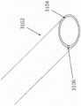
Fig. 9A and 9B illustrate an embodiment of a guidewire guard.
FIG. 10 illustrates an embodiment of an outer hypotube.
FIG. 11 illustrates an embodiment of a medial axis hypotube.
FIG. 12A illustrates an embodiment of the medial axis hypotube of FIG. 11 in a flattened format.
Fig. 12B illustrates an embodiment of an outer retaining ring.
FIG. 13 illustrates an embodiment of a track assembly.
Figure 14 illustrates an embodiment of an inner assembly.
FIG. 15 illustrates a cross-section of the bladder.
Fig. 16 illustrates an embodiment of a delivery system handle.
Fig. 17 illustrates a cross-section of the handle of the delivery system of fig. 16.
Fig. 18 illustrates a schematic diagram of a spaced delivery path.
Fig. 19 illustrates a schematic view of a valve prosthesis positioned within a native mitral valve.
Fig. 20 shows a valve prosthesis frame positioned within a heart.
Fig. 21-23 show steps of a method for delivering a valve prosthesis to an anatomical location.
Fig. 24A-24B illustrate a method of a track delivery system.
FIGS. 25A-25B illustrate an embodiment of a planetary gear design.
Fig. 26A-26B illustrate embodiments of a flexible shaft and a stiffening sheath.
Fig. 27 illustrates an embodiment of a threaded component.
Fig. 28A-28C illustrate bendable, aligned shafts.
29A-29C illustrate embodiments of the disclosed rotatable shaft.
Fig. 30, 31A, and 31B illustrate axial configurations of non-keyed (fig. 30) and keyed (fig. 31, 31A, and 31B).
32A-36 illustrate an embodiment of a tether release mechanism.
Fig. 37-39B illustrate an embodiment of a capsule configuration.
Fig. 40 illustrates another embodiment of a delivery system handle with an embodiment of a failsafe knob (failsafe knob).
Fig. 41A illustrates a cross-section of the failsafe knob of fig. 40 in a first configuration.
Fig. 41B illustrates a cross-section of the failsafe knob of fig. 40 in a second configuration.
Fig. 41C-41F illustrate schematic diagrams of example attachment mechanisms.
Fig. 42A illustrates a cross-section of an embodiment of an indicator knob in a first configuration.
FIG. 42B illustrates a cross-section of the indicating knob of FIG. 42A in a second configuration.
Detailed Description
The present specification and drawings provide aspects and features of the present disclosure in the context of several embodiments of replacement heart valves, delivery systems, and methods configured for use in the vasculature of a patient (e.g., for replacing a native heart valve in a patient). These embodiments may be discussed in connection with replacing a particular valve, such as a patient's aortic, tricuspid, or mitral valves. However, it should be understood that the features and concepts discussed herein may be applied to products other than heart valve implants. For example, the controlled positioning, deployment, and fixation features described herein may be applied to medical implants, such as other types of expandable prostheses, for use elsewhere in the body, such as within arteries, veins, or other body cavities or locations. In addition, the specific features of the valve, delivery system, etc. should not be considered limiting, and features of any one embodiment discussed herein can be combined with features of other embodiments as desired and appropriate. While certain embodiments described herein are described in connection with transfemoral delivery routes, it should be understood that these embodiments may be used with other delivery routes, such as, for example, transapical or transjugular routes. Moreover, it is to be understood that certain features described in connection with some embodiments may be combined with other embodiments, including those described in connection with different delivery paths.
Delivery system
Fig. 1 illustrates an embodiment of a delivery device, system or assembly 10. The delivery system 10 may be used to deploy a prosthesis, such as a replacement heart valve, in vivo. In some embodiments, the delivery system 10 can use a bi-planar deflection path to properly deliver the prosthesis. The replacement heart valve can be delivered to the mitral or tricuspid annulus or other heart valve location of the patient in various ways, such as through open-view surgery, minimally invasive surgery, and percutaneous or transcatheter delivery through the patient's vasculature. An exemplary transfemoral route can be found in U.S. patent publication No. 2015/0238315 (incorporated herein by reference in its entirety), filed on day 2, month 20, 2015. Although the delivery system 10 is described in connection with a percutaneous delivery pathway, and more specifically in connection with a trans-femoral arterial delivery pathway, it should be understood that the features of the delivery system 10 are applicable to other delivery systems, including delivery systems for transapical delivery pathways.
The delivery system 10 may be used to deploy a prosthesis in vivo, such as a replacement heart valve as described elsewhere in this specification. The delivery system 10 may receive and/or cover portions of a prosthesis, such as the first end 301 and the second end 303 of the prosthesis 70 shown in fig. 3A below. For example, the delivery system 10 may be used to deliver an expandable implant or prosthesis 70, wherein the prosthesis 70 includes a first end 301 and a second end 303, and wherein the second end 303 is configured to deploy or expand prior to the first end 301.
Fig. 2A further shows an example of a prosthesis 70 that may be inserted into the delivery system 10, particularly into the implant holding area 16. For ease of understanding, in fig. 2A, the prosthesis is shown with only the bare metal frame illustrated. The implant or prosthesis 70 may take any number of different forms. While a specific example of a frame of a prosthesis is shown in fig. 3A, it will be understood that other designs may be used. The prosthesis 70 may include one or more sets of anchors, such as a distal (or ventricular) anchor 80 extending proximally when the prosthetic frame is in the expanded configuration and a proximal (or atrial) anchor 82 extending distally when the prosthetic frame is in the expanded configuration. The prosthesis may further include struts 72, and the struts 72 may terminate at a first end 301 in a mushroom-shaped projection 74. Further discussion can be found in U.S. publication No. 2015/0328000A1, published 2015, 11, 19, which is incorporated herein by reference in its entirety.
In some embodiments, the delivery system 10 may be used in conjunction with a replacement aortic valve such as that shown in fig. 3B. In some embodiments, the delivery system 10 can be modified to support and deliver a replacement aortic valve. However, the procedures and structures discussed below may be similarly used to replace a mitral valve, tricuspid valve, or aortic valve.
Other details and exemplary designs of prostheses are described in U.S. patent nos. 8,403,983, 8,414,644, 8,652,203 and U.S. patent publication nos. 2011/0313515, 2012/0215303, 2014/0277390, 2014/0277422, 2014/0277427, 2018/0021129, and 2018/0055629, which are incorporated herein in their entirety by reference and made a part of this specification. Further details and embodiments of the replacement heart valve or prosthesis and methods of implanting the same are described in U.S. publication nos. 2015/0328000 and 2016/0317301, each of which is incorporated herein by reference in its entirety and made a part of this specification.
The delivery system 10 may be relatively flexible. In some embodiments, the delivery system 10 is particularly adapted to deliver a replacement heart valve to a mitral valve location via a transseptal approach (e.g., between the right atrium and the left atrium, via a transseptal puncture).
As shown in fig. 1, the delivery system 10 may include a shaft assembly 12, the shaft assembly 12 including a proximal end 11 and a distal end 13, with a handle 14 coupled to the proximal end of the assembly 12. The shaft assembly 12 may be used to hold a prosthesis to advance the prosthesis through the vasculature to a treatment site. The delivery system 10 may further include a relatively rigid integral (live-on) sheath 51 surrounding the shaft assembly 12, which may prevent unwanted movement of the shaft assembly 12. The integral sheath 51 may be attached to the proximal end of the shaft assembly 12 proximal to the handle 14 (e.g., at the sheath hub). The shaft assembly 12 may include an implant holding area 16 at its distal end that may be used for this purpose (which is shown in fig. 2A-2B, where fig. 2A shows the prosthesis 70 and fig. 2B with the prosthesis 70 removed). In some embodiments, the shaft assembly 12 may retain the expandable prosthesis in a compressed state at the implant retention area 16 to advance the prosthesis 70 in vivo. The shaft assembly 12 may then be used to allow controlled expansion of the prosthesis 70 at the treatment site. In some embodiments, the shaft assembly 12 may be used to allow for orderly controlled expansion of the prosthesis 70, as discussed in detail below. The implant holding area 16 is shown in fig. 2A-2B at the distal end of the delivery system 10, but may be at other locations. In some embodiments, the prosthesis 70 may be rotated within the implant holding region 16, such as selected by rotation of the inner shaft assembly 18 discussed herein.
As shown in the cross-sectional views of fig. 2A-2B, the distal end of the delivery system 10 may include one or more subassemblies, such as an outer sheath assembly 22, a middle shaft assembly 21, a track assembly 20, an inner shaft assembly 18, and a nose cone assembly 31, which will be described in more detail below. In some embodiments, the delivery system 10 may not have all of the assemblies disclosed herein. For example, in some embodiments, as described in the embodiments of fig. 25-36 below, a complete bottom bracket assembly may not be incorporated into the delivery system 10. In some embodiments, the assemblies disclosed below may be in a different radial order than that discussed.
In particular, embodiments of the disclosed delivery system 10 may utilize steerable tracks in the track assembly 20 to steer the distal end of the delivery system 10, allowing for proper positioning of the implant within the patient. As discussed in detail below, the steerable track may be, for example, a track shaft that extends from the handle 14 through the delivery system 10 generally to the distal end. In some embodiments, the steerable track has a distal end that terminates proximate the implant holding area 16. The user may manipulate the bending of the distal end of the track, thereby bending the track in a particular direction. In a preferred embodiment, the track has more than one bend along its length, thereby providing multiple bend directions. When the track is curved, it presses against the other assemblies to also curve them, and thus, the other assemblies of the delivery system 10 can be configured to maneuver with the track as a single unit that mates to provide full maneuverability of the distal end of the delivery system.
Once the track is maneuvered to a particular location within the patient's body, the prosthesis 70 may be advanced along or relative to the track and released into the body by movement of the other sheath/shaft relative to the track. For example, the track may be bent into a desired location within the body to guide the prosthesis 70, such as toward the native mitral valve. Other assemblies (e.g., the outer sheath assembly 22, the middle shaft assembly 21, the inner assembly 18, and the nose cone assembly 31) can passively follow the curvature of the track. In addition, other assemblies (e.g., the outer sheath assembly 22, the middle shaft assembly 21, the inner assembly 18, and the nose cone assembly 31) can be advanced together (e.g., relatively together, sequentially, simultaneously, nearly simultaneously with one actuator) relative to the track while maintaining the prosthesis 70 in the compressed position, without releasing or expanding the prosthesis 70 (e.g., within the implant holding region 16). Other assemblies (e.g., the outer sheath assembly 22, the hub assembly 21, the inner assembly 18, and the nose cone assembly 31) can be advanced together distally or proximally relative to the track. In some embodiments, only the outer sheath assembly 22, the bottom bracket assembly 21, and the inner assembly 18 are advanced together over the track. Thus, the nose cone assembly 31 may still be in the same position. The assemblies may be translated relative to the inner assembly 18 separately, sequentially or simultaneously to release the implant 70 from the implant holding area 16.
Fig. 2C illustrates the sheath assembly (in particular the outer sheath assembly 22), the bottom bracket assembly 21, the inner shaft assembly 18, and the nose cone assembly 31 having been translated distally along the track assembly 20, with further details regarding the assemblies below. In some embodiments, the sheath assembly 22, the bottom bracket assembly 21, the inner shaft assembly 18, and the nose cone assembly 31 translate together (e.g., relatively together, sequentially, simultaneously, nearly simultaneously with one actuator). This distal translation may occur while the implant 70 is still in the compressed configuration within the implant holding area 16.
As shown in fig. 2A-2C and further shown in fig. 4-8, starting with the outermost assembly, the delivery system may include an outer sheath assembly 22, the outer sheath assembly 22 forming a radially outer covering or sheath to surround the implant holding area 16 and prevent radial expansion of the implant. In particular, the outer sheath assembly 22 may prevent radial expansion of the distal end of the implant. Moving radially inward, the midshaft assembly 21 may be comprised of a midshaft hypotube 43, the distal end of which is attached to an outer retaining member or ring 42 to radially retain a portion of the prosthesis, such as the proximal end of the prosthesis 70, in a compact configuration. The bottom bracket assembly 21 may be located within the cavity of the outer sheath assembly 22. Further moving inward, track assembly 20 may be configured for maneuverability, as described above and further below. Track assembly 20 may be located within a cavity of bottom bracket assembly 21. Further inward movement, the inner shaft assembly 18 may consist of an inner shaft with a distal end attached to an inner retaining member or ring 40 (such as a PEEK ring) to axially retain a prosthesis (e.g., a proximal end of a prosthesis). The inner shaft assembly 18 may be located within a cavity of the track assembly 20. Further, the most radially inward assembly is a nose cone assembly 31, which includes a nose cone shaft 27, the distal end of which is connected to a nose cone 28. The nose cone 28 may have a tapered tip. The nose cone assembly 31 is preferably located within the lumen of the inner shaft assembly 18. The nose cone assembly 31 may include a lumen for passing a guidewire therethrough.
The shaft assembly 12, and more particularly the nose cone assembly 31, the inner assembly 18, the track assembly 20, the middle shaft assembly 21, and the outer sheath assembly 22, may be collectively configured to deliver a prosthesis 70 (shown in figure 2A) located within the implant holding area 16 to a treatment site. One or more of the subassemblies may then be moved to allow the prosthesis 70 to be released at the treatment site. For example, one or more subassemblies may be moved relative to one or more other subassemblies. The handle 14 can include various control mechanisms that can be used to control the movement of the various subassemblies, which will also be described in more detail below. In this manner, the prosthesis 70 may be controllably loaded onto the delivery system 10 and then deployed within the body. Further, handle 14 may provide steering to track assembly 20, thereby providing bending/flexing/steering to the distal end of delivery system 10.
As will be discussed below, the inner retaining member 40, the outer retaining ring 42, and the outer sheath assembly 22 may cooperate to retain the prosthesis 70 in a compact configuration. In fig. 2A, internal retaining member 40 is shown engaging strut 72 at proximal end 301 of prosthesis 70. For example, slots located between radially extending teeth on the internal retaining member 40 may receive and engage the struts 72, and the struts 72 may terminate in mushroom-shaped projections 74 on the proximal end of the prosthesis 70. The bottom bracket assembly 21 may be positioned on the inner retaining member 40 such that the first end 301 of the prosthesis 70 is captured between the inner retaining member 40 and the outer retaining ring 42, thereby securely attaching it to the delivery system 10 between the bottom bracket assembly 21 and the outer retaining ring 42. The outer sheath assembly 22 may be positioned to cover the second end 303 of the prosthesis 70.
The outer retaining member 42 may be attached to the distal end of the medial axis hypotube 43, the medial axis hypotube 43 may in turn be attached proximally to the proximal tube 44, and the proximal tube 44 may in turn be attached proximally to the handle 14. When in the compressed position, the external retaining member 42 may provide further stability to the prosthesis 70. The outer retaining member 42 may be positioned over the inner retaining member 40 such that the proximal end of the prosthesis 70 is captured therebetween, thereby securely attaching it to the delivery system 10. The outer retaining member 42 can encircle a portion of the prosthesis 70, specifically the first end 301, to prevent expansion of the prosthesis 70. Further, the bottom bracket assembly 21 may be translated proximally relative to the inner assembly 18 into the outer sheath assembly 22, thereby exposing the first end 301 of the prosthesis 70 held within the outer retaining member 42. In this manner, the external retaining member 42 may be used to help secure or release the prosthesis 70 from the delivery system 10. Although the outer retaining member 42 may have a cylindrical or elongated tubular shape and may be referred to as an outer retaining ring, the specific shape is not limited.
The central axis hypotube 43 itself may be made of, for example, high Density Polyethylene (HDPE) as well as other suitable materials described herein. The central axial hypotube 43 may be formed from longitudinally pre-compressed HDPE tubing, which may provide certain benefits. For example, a pre-compressed HDPE tube may apply a force distally to the outer retaining member 42, thereby preventing accidental, unintended, and/or premature release of the prosthesis 70. Specifically, the distal end of outer retaining member 42 is retained distal to inner retaining member 40 by the distal force of medial axis hypotube 43, thereby preventing outer retaining member 42 from moving proximally of inner retaining member 40 until the user desires to release prosthesis 70. This may still be true even when delivery system 10 is bent/deflected at an acute angle. Further disclosure regarding outer retaining member 42 and mid-shaft hypotube 43 may be found in U.S. patent publication No. 2016/0317301, which is incorporated herein by reference in its entirety.
As shown in fig. 2A, the distal anchor 80 can be in a delivery configuration in which the distal anchor 80 is generally directed distally (axially away from the body of the prosthetic frame and away from the handle of the delivery system as shown). The outer sheath assembly 22 may constrain the distal anchor 80 in this delivery configuration. Thus, when the outer sheath 22 is proximally withdrawn, the distal anchor 80 may flip over (e.g., bend approximately 180 degrees) to a deployed configuration (e.g., point generally proximally). Fig. 2A also shows a proximal anchor 82 that extends distally within the outer sheath assembly 22 in its delivery configuration. In other embodiments, the distal anchor 80 can be held to point generally proximally and be compressed against the body of the prosthetic frame in the delivery configuration.
The delivery system 10 with the prosthesis 70 pre-installed may be provided to the user. In other embodiments, the prosthesis 70 may be loaded onto the delivery system shortly before use, such as by a physician or nurse.
Delivery system assembly
Fig. 4-8 illustrate additional views of the delivery system 10 with the various assemblies translated proximally and described in detail.
Starting with the outermost assembly shown in fig. 4, the outer sheath assembly 22 may include an outer proximal shaft 102 attached directly to the handle 14 at its proximal end and an outer hypotube 104 attached at its distal end. Balloon 106 may then be attached generally at the distal end of outer hypotube 104. In some embodiments, the size of capsule 106 may be 28French or less. These components of the outer sheath assembly 22 may form a cavity for other subassemblies to pass therethrough.
The outer proximal shaft 102 may be a tube, and is preferably formed of plastic, but may also be a metal hypotube or other material. Outer hypotube 104 may be a metal hypotube, which in some embodiments may be cut or have slots, as discussed in detail below. Outer hypotube 104 may be covered or encapsulated with ePTFE, PTFE, or other polymer/material layers such that the outer surface of outer hypotube 104 is substantially smooth.
A capsule 106 may be located at the distal end of outer proximal shaft 102. Bladder 106 may be a tube formed from a plastic or metal material. In some embodiments, bladder 106 is formed from ePTFE or PTFE. In some embodiments, this capsule 106 is relatively thick to prevent tearing and to help maintain the self-expanding implant in a compact configuration. In some embodiments, the material of bladder 106 is the same as the coating on outer hypotube 104. As shown, the diameter of bladder 106 may be larger than outer hypotube 104, but in some embodiments, the diameter of bladder 106 may be similar to hypotube 104. In some embodiments, bladder 106 can include a larger diameter distal portion and a smaller diameter proximal portion. In some embodiments, there may be a step or taper between the two portions. Bladder 106 may be configured to retain prosthesis 70 in a compressed position within bladder 106. Further construction details of bladder 106 are discussed below.
The sheath assembly 22 is configured to be individually slidable relative to the other assemblies. Further, the outer sheath assembly 22 can slide distally and proximally with respect to the track assembly 22, along with the midshaft assembly 21, the inner assembly 18 and the nose cone assembly 31.
Moving radially inward, the next assembly is a bottom bracket assembly 21. FIG. 5 shows a view similar to FIG. 4, but with the outer sheath assembly 22 removed, exposing the bottom bracket assembly 21.
The bottom bracket assembly 21 may include a bottom bracket hypotube 43 attached generally at its proximal end to a bottom bracket proximal tube 44, which in turn may be attached at its proximal end to the handle 14; and an outer retaining ring 42 located at the distal end of the medial hypotube 43. Thus, the outer retaining ring 42 may be attached substantially at the distal end of the medial axis hypotube 43. These components of bottom bracket assembly 21 may form a cavity for other subassemblies to pass therethrough.
Similar to the other assemblies, the medial axis hypotube 43 and/or the medial axis proximal tube 44 may comprise a tube, such as a hypotube or hypotube (not shown). The tube may be made of one of any number of different materials, including nitinol, stainless steel, and medical grade plastic. The tube may be a single piece of tube or multiple pieces of tube joined together. The use of a tube made of multiple pieces allows the tube to provide different properties, such as rigidity and flexibility, along different sections of the tube. The medial hypotube 43 may be a metal hypotube, which in some embodiments may be cut or slotted, as discussed in detail below. The central axial hypotube 43 may be covered or encapsulated with a layer of ePTFE, PTFE, or other material such that the outer surface of the central axial hypotube 43 is substantially smooth.
The outer retention ring 42 may be configured as a prosthesis retention mechanism that may be used to engage the prosthesis 70, as discussed with respect to fig. 2A. For example, the outer retention ring 42 may be a ring or covering configured to radially cover the struts 72 on the prosthesis 70. The outer retention ring 42 may also be considered part of the implant holding area 16 and may be proximal to the implant holding area 16. With the struts or other portions of the prosthesis 70 engaged with the internal retaining member 40, the external retaining ring 42 can cover both the prosthesis 70 and the internal retaining member 40 to secure the prosthesis 70 to the delivery system 10, as described below. Thus, the prosthesis 70 can be sandwiched between the inner retention member 40 of the inner shaft assembly 18 and the outer retention ring 42 of the middle shaft assembly 21.
The bottom bracket assembly 21 is arranged to be individually slidable relative to the other assemblies. Further, the bottom bracket assembly 21 is slidable distally and proximally relative to the track assembly 22, along with the outer sheath assembly 22, the intermediate inner assembly 18, and the nose cone assembly 31.
Next, radially inward of bottom bracket assembly 21 is track assembly 20. FIG. 6A shows substantially the same view as FIG. 5, but with bottom bracket assembly 21 removed, exposing track assembly 20. Fig. 6B further shows a cross section of track assembly 20 to view the pulling wire. Track assembly 20 may include a track shaft 132 (or track) attached to handle 14 generally at a proximal end thereof. The rail shaft 132 may be comprised of a rail proximal shaft 134 attached directly to the handle at the proximal end and a rail hypotube 136 attached to the distal end of the rail proximal shaft 134. The rail hypotube 136 may also include an atraumatic rail tip at its distal end. Further, as shown in fig. 6, the distal end of the rail hypotube 136 may abut the proximal end of the inner retaining member 40. In some embodiments, the distal end of the rail hypotube 136 may be spaced apart from the internal retaining member 40. These components of the rail shaft assembly 20 may form a cavity for other subassemblies to pass therethrough.
As shown in fig. 6B, one or more puller wires are attached to the inner surface of rail hypotube 136, which can be used to apply force to rail hypotube 136 and manipulate rail assembly 20. The puller wire may extend distally from a knob in the handle 14 discussed below to the track hypotube 136. In some embodiments, the pull wires may be attached at different longitudinal locations on the rail hypotube 136, thereby providing multiple bending locations in the rail hypotube 136 to allow multi-dimensional manipulation.
In some embodiments, the distal puller wire 138 may extend to the distal section of the orbital hypotube 136 and the two proximal puller wires 140 may extend to the proximal section of the orbital hypotube 136, however, other numbers of puller wires may be used and the specific number of puller wires is not limited. For example, two pull wires may extend to a distal position, while a single pull wire may extend to a proximal position. In some embodiments, ring-like structures attached to the interior of the orbital hypotube 136, such as the proximal ring 137 and the distal ring 135, referred to as pull wire connectors, may be used as attachment locations for pull wires. In some embodiments, track assembly 20 may include a distal pull wire connector 135 and a proximal pull wire connector 139. In some embodiments, the puller wire may be directly connected to the inner surface of the rail hypotube 136.
The distal puller wire 138 may be connected (alone or through the connector 135) at approximately the distal end of the orbital hypotube 136. A proximal puller wire 140 may be attached (alone or through connector 137) from the proximal end at a location along approximately one quarter, one third, or one half of the length of the orbital hypotube 136. In some embodiments, the distal puller wire 138 may pass through a small diameter puller wire lumen 139 (e.g., tube, hypotube, cylinder) attached on the interior of the orbital hypotube 136. This may prevent the wire 138 from pulling the orbital hypotube 136 at a location near the distal connection. In addition, the lumen 139 can act as a compression coil to reinforce the proximal portion of the orbital hypotube 136 and prevent unwanted bending. Thus, in some embodiments, lumen 139 is located only on the proximal half of orbital hypotube 136. In some embodiments, each distal wire 139 may use a plurality of lumens 139, such as longitudinally spaced apart or adjacent. In some embodiments, a single lumen 139 is used for each distal wire 139. In some embodiments, the lumen 139 can extend into the distal half of the orbital hypotube 136. In some embodiments, the lumen 139 is attached to the outer surface of the orbital hypotube 136. In some embodiments, the cavity 139 is not used.
For pairs of proximal puller wires 140, the wires may be spaced approximately 180 ° from each other to allow manipulation in both directions. Similarly, if a pair of distal pull wires 138 are used, the wires may be spaced approximately 180 ° from each other to allow manipulation in both directions. In some embodiments, the pair of distal puller wires 138 and the pair of proximal puller wires 140 can be spaced approximately 90 ° from each other. In some embodiments, the pair of distal puller wires 138 and the pair of proximal puller wires 140 can be spaced approximately 0 ° from each other. However, other locations for pulling the filament may be used, and the particular location for pulling the filament is not limited. In some embodiments, the distal puller wire 138 may pass through a lumen 139 attached within the lumen of the orbital hypotube 136. This may prevent axial forces on the distal puller wire 138 from bending in the proximal section of the orbital hypotube 136.
Moving radially inward, the next assembly is the inner shaft assembly 18. FIG. 7 shows substantially the same view as FIG. 6A, but with the track assembly 20 removed, exposing the inner shaft assembly 18.
The inner shaft assembly 18 can include an inner shaft 122 attached to the handle 14 generally at its proximal end, and an inner retaining ring 40 at the distal end of the inner shaft 122. The inner shaft 122 itself may be comprised of an inner proximal shaft 124 attached directly to the handle 14 at a proximal end and a distal section 126 attached to a distal end of the inner proximal shaft 124. Thus, the inner retaining ring 40 may be attached generally at the distal end of the distal section 126. These components of the inner shaft assembly 18 may form a cavity for other subassemblies to pass therethrough.
Similar to the other assemblies, the inner proximal shaft 124 may comprise a tube, such as a hypotube or hypotube (not shown). The tube may be made of one of any number of different materials, including nitinol, cobalt chromium alloy, stainless steel, and medical grade plastic. The tube may be a single piece of tube or multiple pieces of tube joined together. A tube comprising multiple pieces may provide different properties, such as rigidity and flexibility, along different sections of the tube. Distal section 126 may be a metal hypotube, which in some embodiments may be cut or slotted, as discussed in detail below. Distal section 126 may be covered or encapsulated by a layer of ePTFE, PTFE, or other material such that the outer surface of distal section 126 is substantially smooth.
The inner shaft assembly 18 is arranged so as to be separately slidable relative to the other assemblies. Further, the inner assembly 18 can slide distally and proximally relative to the track assembly 22, along with the outer sheath assembly 22, the midshaft assembly 21 and the nose cone assembly 31.
Moving further inwardly from the inner shaft assembly 18 is a nose cone assembly 31, also shown in fig. 8. This may be a nose cone shaft 27 and, in some embodiments, may have a nose cone 28 on its distal end. The nose cone 28 may be made of polyurethane for atraumatic access and to minimize damage to the venous vasculature. The nose cone 28 may also be radiopaque to provide visibility under fluoroscopy.
The nosecone shaft 27 can include a lumen sized and configured to slidably receive a guidewire such that the delivery system 10 can be advanced over the guidewire through the vasculature. However, embodiments of the system 10 discussed herein may not use a guidewire, and thus the nosecone shaft 27 may be solid. The nose cone shaft 27 may be connected from the nose cone 28 to the handle, or may be formed from different parts such as other components. Further, the nose cone shaft 27 may be formed of a different material (e.g., plastic or metal) similar to the materials described in detail above.
In some embodiments, the nose cone shaft 27 includes a guide wire guard 1200 located on a portion of the nose cone shaft 27. An example of such a guide wire guard can be found in fig. 9A-B. In some embodiments, the guidewire guard 1200 may be proximal to the nose cone 28. In some embodiments, the guidewire guard 1200 may translate along the nose cone axis 27. In some embodiments, the guidewire guard 1200 may be locked in place along the nose cone shaft 27. In some embodiments, the guidewire guard 1200 may be located at least partially within the nose cone 28.
Advantageously, the guide wire guard 1200 may allow for smooth tracking of the guide wire with the implant 70 loaded and may provide a large axial diameter landing zone (plating zone) for the distal end of the implant so that the distal end of the implant 70 may be properly deployed and arranged in a uniform radial arrangement. This uniformity allows for proper expansion. In addition, the guidewire guard 1200 may prevent kinking or damage to the nose cone shaft 27 during compression/crimping of the prosthesis 70, which may exert large compressive forces on the nose cone shaft 27. The guide wire guard 1200 may provide a protective surface as the prosthesis 70 may be crimped over the guide wire guard 1200 rather than directly over the nose cone shaft 27.
As shown, the guidewire guard 1200 may include a lumen 1202 configured to surround the nose cone shaft 27. The guidewire guard 1200 may include a larger diameter distal end 1204 and a smaller diameter proximal end 1206. In some embodiments, the dimensional change between the two ends may be tapered, or may be a step 1208 as shown in fig. 9A. The distal end 1204 may include a plurality of indentations (indices) 1210 to make grasping easier by a user, but may not be included in all embodiments. Both the proximal end 1206 and the distal end 1204 may be generally cylindrical, but the particular shape of the guidewire guard 1200 is not limited.
The distal end of the prosthesis 70 may be crimped such that it is in radial contact with the proximal end 1206 of the guidewire guard 1200. This may allow the prosthesis 70 to properly deploy around the circumference of the proximal end 1206 of the guidewire guard 1200. In some embodiments, the distal end of prosthesis 70 may abut longitudinally against the proximal end of distal end 1204 (e.g., at step 1208), thereby providing a longitudinal stop.
Fig. 9B shows an alternative embodiment of a guidewire guard 1200' having a more tapered configuration. As shown, the proximal end 1206 'of the guide wire guard 1200' can be a single radially outward taper 1208 'to the distal end 1204' of the guide wire guard 1200', and the distal end 1204' can be substantially cylindrical. The guidewire guard 1200 'may also include a lumen 1202' for receiving the nosecone shaft 27.
The nose cone assembly 31 is arranged so as to be individually slidable relative to the other assemblies. Further, the nose cone assembly 31 can slide distally and proximally with the outer sheath assembly 22, the bottom bracket assembly 21, and the inner assembly 18 relative to the track assembly 22.
In some embodiments, one or more spacer sleeves (not shown) may be used between different assemblies of the delivery system 10. For example, a spacer sleeve may be concentrically located between the bottom bracket assembly and track assembly 20, generally between mid hypotube 43 and track hypotube 136. In some embodiments, the spacer sleeve may be substantially embedded in hypotube 43 of bottom bracket assembly 21, such as on an inner surface of bottom bracket assembly 21. In some embodiments, a spacer sleeve may be concentrically located between the track assembly 20 and the inner assembly 18, generally within the track hypotube 136. In some embodiments, a spacer sleeve may be used between the outer sheath assembly 22 and the bottom bracket assembly 21. In some embodiments, a spacer sleeve may be used between the inner assembly 18 and the nose cone assembly 31. In some embodiments, 4, 3, 2, or 1 of the spacer sleeves described above may be used. Spacer sleeves may be used in any of the above-described positions.
The spacer sleeve may be made of a polymeric material (e.g. braided) ) Made and may be lined on the inside diameter with, for example, PTFE, although the specific material is not limiting. The spacer sleeves may advantageously reduce friction between the
 steerable track assembly 20 and its surrounding assemblies. Thus, the spacer sleeve may act as a buffer between the track assembly 20 and the inner assembly 18/nose cone assembly/30. Further, the spacer sleeve may occupy any radial gap between the assemblies, preventing compression or buckling (snaging) of the assemblies during handling. In some embodiments, the spacer sleeve may include cuts or slots to facilitate bending of the spacer sleeve. In some embodiments, the spacer sleeve may not include any slots and may be a smooth cylindrical feature.
The spacer sleeve may be mechanically accommodated by other cavities and components, and thus not physically attached to any other component, thereby allowing the spacer sleeve to "float" in this region. The floating aspect of the spacer sleeve allows it to move to where it is needed during deflection and provides a bearing surface/bearing surfaces for support and/or lubrication. Thus, the floating aspect allows the delivery system 10 to maintain the deflection force. However, in some embodiments, the spacer sleeve may be connected to other components.
Hypotube/shaft construction
As discussed above, the outer sheath assembly 22, the central shaft assembly 21, the inner assembly 18, and the track assembly 20 may include an outer hypotube 104, a central shaft hypotube 43, a distal section 126, and a track hypotube 136, respectively. Each of the hypotubes/segments/shafts can be laser cut to include a number of slots to create a curved pathway for the delivery system. Although different slot assemblies are discussed below, it should be understood that any hypotube can have the slot configuration discussed below. Fig. 10-14 show different hypotubes in isolation.
As shown in fig. 10, outer hypotube 104 may generally be formed from a metal coil or a plurality of metal coils. In some embodiments, outer hypotube 104 may be formed from a proximal metal coil 107 and a distal metal coil 108. As shown in fig. 10, the proximal metal coil 107 and the distal metal coil 108 may be longitudinally separated by a tube segment 110. However, in some embodiments, the proximal metal coil 107 and the distal metal coil 108 are connected. The proximal and distal metal coils 107, 108 may be attached to the outer surface of the tube segment 110, for example, at the distal end of the proximal metal coil 107 and the proximal end of the distal metal coil 108, to form the complete outer hypotube 104. In some embodiments, the proximal metal coil 107 and the distal metal coil 108 are substantially identical. In some embodiments, the proximal metal coil 107 and the distal metal coil 110 are different, for example, in terms of spacing between coils, curvature, diameter, and the like. In some embodiments, such as when distal metal coil 108 forms the large diameter of capsule 106, distal metal coil 108 has a larger diameter than proximal metal coil 107. In some embodiments, they have the same diameter. In some embodiments, one or both of the metal coils 108/107 may form the bladder 106. The coils may be coated with a polymer layer, such as described in detail below with respect to the bladder configuration. The coil configuration may allow the outer hypotube 104 to follow the trajectory in any desired direction.
Moving radially inward, FIGS. 11-12B show that the medial axis hypotube 43 may be a metal laser cut hypotube, such as a laser cut Nitinol hypotube. Fig. 12A illustrates the planar pattern of fig. 11. As shown in the figures, hypotube 43 may have a plurality of slots/holes cut into the hypotube. In some embodiments, the cutting pattern may be the same throughout. In some embodiments, the medial axis hypotube 43 may have different sections with different cutting patterns.
For example, the proximal end of the medial hypotube 43 may be a first section 210 having a plurality of circumferentially extending pairs of slots 213 longitudinally spaced along the first section 211. In general, two slots are cut around each circumferential location, forming almost half of a circumference. Thus, two backbones 215 are formed between the slots 213 that extend along the length of the first section 211. The slot pair 213 may consist of a first thin slot 217. The second slot 221 of each slot pair 213 may be thicker than the first slot 217, such as 1, 2,3, 4, or 5 times thicker. In some embodiments, the second slot 217 may have substantially the same longitudinal thickness throughout the slot. In some embodiments, each slot of the pair of slots 213 may terminate in a tear drop shape 219 to facilitate bending.
Moving distally, the medial axis hypotube 43 may include a second section 220 having a plurality of slot pairs 222. Similar to the first section 211, the second section 220 may have a plurality of circumferentially extending slots longitudinally spaced along the second section 220. In general, two slots (e.g., one slot pair 222) are cut around each circumferential location, forming almost half of a circumference. Thus, a "backbone" 224 is formed between the slots that extends along the length of the second section 220. Each slot pair 222 may include a first slot 226 that is generally thin and without a particular shape (e.g., which may appear the same as slot 213 in the first section 211) and a second slot 228 that is significantly thicker in the longitudinal direction than the first slot 226. The second slot 228 may be narrower at its ends and thicker in the longitudinal direction at its middle portion, thereby forming a curved slot. Moving longitudinally along the second section 220, each slot pair 222 may be offset by approximately 45 degrees or 90 degrees compared to longitudinally adjacent slot pairs 222. In some embodiments, the second slot pair 222 is offset by 90 degrees from the adjacent first slot pair 222, and a third slot pair 222 adjacent to the second slot pair 222 may have the same configuration as the first slot pair 222. This repeating pattern may extend along the length of the second section 220, providing a particular direction of bending caused by the second slot 228 of the pair of slots 222. Therefore, the "stem" 224 is shifted in circumferential position by the offset of the adjacent shift groove pair 222. In some embodiments, each slot of the pair of slots 222 may terminate in a teardrop shape 229 to facilitate bending.
Moving distally, the medial hypotube 43 can have a third section 230, the third section 230 having a plurality of slots. An outer retaining ring 240 may be attached to the distal end of the third section 230. The third section 230 can have circumferentially extending pairs of slots 232, each slot of the pair extending about halfway circumferentially to form two spines 234. The slot pair 232 may consist of a first thin slot 236, similar to the slot 213 discussed in the first section 211. The second slot 238 of each slot pair 232 may be thicker than the first slot 236, such as 1, 2,3, 4, or 5 times thicker. In some embodiments, unlike the second slot 228 of the second section 220, the second slot 238 may have substantially the same longitudinal thickness throughout the slot. The first and second slots 236, 238 may be circumferentially aligned along the length of the third section 230 such that all of the first slots 236 are in the same circumferential position and all of the second slots 238 are in the same circumferential position. The second slot 238 may be aligned with one of the circumferential positions of the second slot 228 of the second section 220. In some embodiments, each slot of the pair of slots 232 may terminate in a teardrop shape 239 to facilitate bending.
In some embodiments, the outer retaining ring stiffener (strengzhener) 240, which may partially or completely circumferentially surround the outer retaining member 40, may also have a plurality of slots/holes/bores, as shown in fig. 11-12. This may allow it to bend along curves (bend over curves), especially along small radius curves (light curves). In some embodiments, the distal end of the stiffening member 240 includes a plurality of substantially circular/elliptical holes 242. This may last for about half the length of the stiffener 240. On the proximal half, one circumferential half of the stiffener 240 may include repeating thin slots 244 spaced by elongated oval holes 246. For example, two circumferentially spaced elongated oval shaped apertures 246 may be between each thin slot 244. In some embodiments, each of the slots 244 may terminate in a tear drop shape 249 to facilitate bending. On the other circumferential half of the proximal section, the stiffener 240 may include a plurality of large slots 248, such as 1, 2,3, 4, or 5 large slots 248 spaced longitudinally. The large slot 248 may be larger in the middle, narrowing toward each circumferential end. The large slot 248 may include a distal flare 247 to promote flexibility.
In addition, the external retention reinforcement 240 may provide strength to reduce deployment forces, protect the prosthesis 70 from any metal layers, and may increase strength. In some embodiments, the liner 240 may be a polymer (e.g., PTFE), but the type of polymer or material is not limited. In some embodiments, the stiffener 240 may be a metal. In some embodiments, the strength member 240 may further include an outer polymer layer/jacket, such as A sheath. This prevents the stiffening
 member 240 from catching on the sheath assembly 22.
In certain embodiments, the outer retention ring 42 may further include a liner for a smooth transition over the prosthesis 70. The liner may be PTFE or etched PTFE, but the specific material is not limited and other friction reducing polymers may be used. As shown in fig. 12B, to prevent delamination during loading of the implant 70, the liner 251 may not be flush at the distal end of the outer retention ring 42. Instead, the liner 251 may be extended and folded over (inverted) at the distal end to cover the distal end of the outer retaining ring 42. In some embodiments, the liner 251 may also cover the outer surface of the stiffener 240. This may form a seamless rolled reinforcement tip of the liner 251. The liner 251 may completely or partially cover the outer surface of the outer retaining ring 42, such as 1/4, 1/3, 1/2, 2/3, 3/4 (or more than 1/4, 1/3, 1/2, 3/4) or all of the outer retaining ring 42. This solution is superior to previously known methods, such as the method disclosed in U.S. patent No. 6,622,367, which is incorporated herein by reference in its entirety, because the application of lined PTFE is not particularly well affixed to the reinforcement or outer jacket. By folding the liner 251 over and fusing it to the outer polymer jacket over the outer retention ring 42 and/or the stiffener 240/outer retention ring 42, this forms a seamless reinforced tip that reduces delamination. Delamination is a serious problem because the delaminated liner can tear and plug during deployment, and the delaminated layers can result in extremely high loading and deployment forces. The layered layers may also cause problems with translation of the cavity by locking the shaft, thereby increasing the need for translation forces.
Next, moving radially inward again, fig. 13 shows an embodiment of an orbital hypotube 136 (distal towards the right). The orbital hypotube 136 may also include a plurality of circumferential slots. The track hypotube 136 may be generally broken into a plurality of different sections. At the proximal end is an uncut (or ungrooved) hypotube section 231. Moving distally, the next section is the proximally slotted hypotube section 133. This section includes a plurality of circumferential slots cut into the orbital hypotube 136. In general, two slots are cut around each circumferential location, forming almost half of a circumference. Thus, two spines are formed between the slots that extend along the length of hypotube 136. This is the section that can be guided by the proximal puller wire 140. Further distal movement is proximal pulling of the location 237 where the wire 140 is attached, thus avoiding the slot. Thus, the section is just distal to the proximal slotted section.
Distal to the proximal pull wire connection region is a distal slotted hypotube section 235. This section is similar to the proximally slotted hypotube section 233, but with significantly more slots cut out of equal length. Thus, distally slotted hypotube section 235 provides easier bending than proximally slotted hypotube section 233. In some embodiments, the proximal slotted section 233 can be configured to undergo approximately 90 degrees of bending at a half inch radius, while the distal slotted section 135 can be bent at approximately 180 degrees within a half inch. Further, as shown in fig. 13, the ridges of the distally slotted hypotube section 235 are offset from the ridges of the proximally slotted hypotube section 233. Thus, the two sections will achieve different bending patterns, allowing for three-dimensional manipulation of track assembly 20. In some embodiments, the ridges may be offset by 30, 45, or 90 degrees, although the specific offset is not limiting. In some embodiments, the proximal slotted hypotube section 233 can comprise a compression coil. This allows the proximal slotted hypotube section 233 to remain rigid to allow the distal slotted hypotube section 235 to make a specific bend.
At the most distal end of the distal slotted hypotube segment 235 is a distal pull wire connection region 241, which in turn is a non-slotted segment of the orbital hypotube 136.
Moving radially inwardly, in fig. 14, the inner assembly 18 is generally comprised of two sections. The proximal section is a slotted or non-slotted hypotube 129. The distal section 126, which at least partially overlaps the outer surface of the proximal hypotube 129, may be designed to be particularly flexible. For example, the distal section 126 may be more flexible than any of the other shafts discussed herein. In some embodiments, the distal section 126 may be more flexible than any of the shafts discussed herein, except for the nosecone shaft 27. In some embodiments, distal section 126 may be a flexible tube or a hypotube. In some embodiments, distal section 126 may be a cable, such as a flexible cable. For example, the cable may wrap several strands of wire, such as metal, plastic, polymer, ceramic, etc., together to form a rope or cable. Because the cable is so flexible, it can more easily bend with track assembly 20. Furthermore, the cables may be smooth, which allows track assembly 20 to track on a smooth surface, eliminating the need for any lining on track assembly 20.
Capsule structure


Fig. 15 shows an embodiment of a capsule 106 that can be used with embodiments of the delivery system 10. Bladder 106 may include any of the materials and properties discussed above. In the case of multiple implant capsules, compression resistance and flexibility are generally balanced, as improved flexibility results in less compression resistance. Therefore, a choice tends to be made between compression resistance and flexibility. However, embodiments of bladder 106 are disclosed that achieve high compression resistance and high flexibility. In particular, bladder 106 may be curved in multiple directions.
In particular, a metal hypotube can provide radial strength and resistance to compression, while a particular slot/cut in the hypotube can enable flexibility of capsule 106. In some embodiments, a thin liner and sheath may surround bladder 106 (e.g., a polymer layer) to prevent any negative interaction between implant 70 and bladder 106.
In some embodiments, bladder 106 may have a particular configuration as shown in fig. 15 to allow it to achieve advantageous properties. Bladder 106 may be made of several different layers to provide this property.
In some embodiments, bladder 106 may be formed from a metal layer 404, with metal layer 404 providing bladder 106 with its structure. This metal layer 404 may include the coil discussed with respect to fig. 10, or may be one or more hypotubes. Bladder 106 is then covered on the outer surface with a polymer layer and on the inner surface with a liner. All of these features will be discussed in detail below.
As described, the metal layer 404 may be, for example, a metal hypotube or a laser cut hypotube. In some embodiments, the metal layer 404 may be a metal coil or spiral as discussed in detail above with respect to fig. 10. Although not limited, the metal layer 404 may have a thickness of 0.007 inches (or about 0.007 inches).
If a metal coil as shown in fig. 10 is used, the coil dimensions may remain the same throughout the length of metal layer 404. However, in some embodiments, the coil dimensions may vary along the length of the metal layer 404. For example, the coils may vary between coils having a gap of 0.014 inches and a pitch of 0.021 inches (e.g., small coils), coils having a gap of 0.020 inches and a pitch of 0.02 inches (e.g., large coils), and coils having a gap of 0.020 and a pitch of 0.027 inches (e.g., large coils spaced). However, these particular dimensions are merely examples, and other designs may be used.
The most distal end of metal layer 404 may be formed by a small coil. Moving proximally, the metal layer 404 may then transition to a large coil section, followed by a small coil section, and then finally, the most proximal section may be the spaced large coil. As an exemplary set of lengths, but without limitation, the length of the distal-most small coil section may be 10mm (or about 10 mm). Moving proximally, the length of adjacent large coil segments may extend 40mm (or about 40 mm) to 60mm (or about 60 mm). These two sections can be found in the distal metal coil 108 shown in fig. 10. Moving to the proximal metal coil 107 shown in fig. 10, the small coil section may be 10mm (or about 10 mm) in length. The remainder of the proximal metal coil 107 may be spaced large coil sections. The length of the spaced large coil sections may be 40mm (or about 40 mm) to 60mm (or about 60 mm) or more.
As noted, the metal layer 404 (coil or hypotube) may be covered by an outer polymer layer or jacket 402. In some embodiments, the outer polymer 402 layer is an elastomer, but the specific material is not limited. In some embodiments, the outer polymer layer 402 may comprise Polytetrafluoroethylene (PTFE) or expanded polytetrafluoroethylene (ePTFE). ePTFE can have very different mechanical properties than PTFE. For example, ePTFE can have much greater flexibility while still maintaining good tensile/elongation properties. In some embodiments, the outer polymer layer 402 may include a thermoplastic elastomer, such as In some embodiments, the
 outer polymer layer 402 may be pre-axially stressed prior to application to the bladder. The thickness of the outer polymer layer 402 can be about 0.006 to 0.008 inches, although the specific thickness is not limited.
The outer polymer layer 402 may be applied to the metal layer 404 to form an outer sheath, such as by reflowing the polymer. In some embodiments, the outer polymer layer 402 may be applied directly onto the metal layer 404. In some embodiments, an adhesive layer 406 may be disposed between the metal layer 404 and the outer polymer layer 402 to facilitate attachment of the outer polymer layer to the metal layer. For example, a fluoropolymer or other soft-hard fluoroelastomer may be applied between the metal layer 404 and the outer layer 402 to attach the two layers together and prevent delamination. In some embodiments, adhesive layer 406 is not used.
In some embodiments, other materials may be included between the metal layer 404 and the outer polymer layer 402 to improve properties. For example, fluorinated Ethylene Propylene (FEP) sections 408 may improve radial strength, particularly when the implant is in a compressed configuration. Although the FEP layer 408 is discussed as a specific material, other high strength polymers, metals, or ceramics may be used, and the specific material is not limited. In some cases, the FEP layer 408 may also act as an adhesive.
Given that there is no limitation on a particular length, the FEP section 408 at the distal end of capsule 106 may have a length of 10mm (or about 10 mm). In some embodiments, the thickness of the FEP section 408 is about 0.003 inches, but this thickness can vary and is not limited by this disclosure. In some embodiments, the different FEP sections 408 (e.g., proximal section and distal portion) may have different thicknesses. In some embodiments, all of the FEP 408 layers have the same thickness. Exemplary thicknesses may be 0.006 inches or 0.003 inches.
Moving to the interior of the metal layer 404, a liner 410 may be included on its radially inner surface. Liner 410 may be formed from a low friction and/or high lubricity material that allows bladder 106 to translate over prosthesis 70 without seizing or damaging portions of prosthesis 70. In some embodiments, the liner 410 may be PTFE, which resists radial expansion and reduces friction with the prosthesis 70.
In some embodiments, the liner 410 is made of ePTFE. However, it can be difficult to reflow solder a standard ePTFE liner 410 onto the inner layer of bladder 106. Accordingly, ePTFE backing layer 410 may be pre-compressed prior to application to the inner layer of bladder 106. In some embodiments, portions of the outer polymer layer 402 and the liner 410 may be in contact with each other. Thus, the ePTFE liner 410 and/or the outer polymer layer 402 can be axially compressed prior to bonding the two layers together. The layers may then be bonded together during manufacturing using reflow soldering techniques. For example, the ePTFE liner 410 may be axially compressed, such as on a mandrel, and the outer polymer layer 402 may be placed thereon. The two layers may then be reflow soldered (e.g., melted under pressure) to make the connection. The combined layers may be slid into and/or around the metal layer 404 discussed herein, and may again be melted under pressure to form the final capsule 106. This technique may allow bladder 106 to maintain flexibility and prevent rupture/tearing.
As noted, in some embodiments, the inner liner 410 may be ePTFE. The surface friction of ePTFE may be about 15% less than standard PTFE and about 40% less than standard extruded thermoplastics used in the art.
In some embodiments, backing layer 410 may extend only along the inner surface of bladder 106 and terminate at a distal end. However, to prevent delamination during loading of implant 70, liner 410 may not be flush at the distal end of capsule 106. Instead, liner 410 can be extended and folded over at the distal end to cover the distal end of bladder 106 and the outer diameter of a portion of outer polymer layer 402. This may form a seamless rolled reinforcement tip of the liner 410. This solution is superior to previously known methods, such as the method disclosed in U.S. patent No. 6,622,367, which is incorporated herein by reference in its entirety, because the application of lined PTFE is not particularly well affixed to the reinforcement or outer jacket. By folding the liner 410 over and fusing it to the outer polymer layer 402, this forms a seamless reinforced bladder that can reduce delamination. Delamination is a serious problem because the delaminated liner can tear and plug during deployment, and the delaminated layers can result in extremely high loading and deployment forces. The layered layers may also cause problems with translation of the cavity by locking the shaft, thereby increasing the need for translation forces.
In some embodiments, another FEP section 412 may be included between liner 410 and metal layer 404. The FEP section 412 may be located on the distal metal coil 108, and the tube 110 transitions between the distal metal coil 108 and the proximal metal coil 107. In some embodiments, the FEP section 412 may extend partially or completely into the proximal metal coil 107.
In some embodiments, the FEP section 412 may be included in the most proximal portion of the proximal metal coil 107. The length of this FEP section 412 is approximately 0.5 inches. In some embodiments, there is a longitudinal gap extending over the distal metal coil 108 between the proximal-most FEP section 412 and the FEP section 412. In some embodiments, the previously mentioned FEP section 412 is continuous.
As shown in fig. 15, the metal layer 404 may stop near the edges of the outer polymer layer 402, liner 410, and FEP section 412. If so, a thicker portion of adhesive layer 409 may be applied at the distal end of metal layer 404 to mate with the distal end of the other layer. However, this section may be removed during manufacturing, so the distal end of metal layer 404 is the distal end of bladder 106, and may then be covered by liner 410. In some embodiments, an extension section distal to metal layer 404 is not used.
Handle (CN)
The track housing 202 may contain two rotatable knobs — a distal pull wire knob 206 and a proximal pull wire knob 208. However, the number of rotatable knobs on the track housing 202 may vary depending on the number of puller wires used. Rotation of the distal pull wire knob 206 may provide a proximal force, providing an axial tension on the distal pull wire 138 and bending the distal slotted section 135 of the orbital hypotube 136. The distal pull wire knob 206 may be rotated in either direction, allowing bending in either direction, which may control the anterior-posterior angle. Rotation of the proximal puller wire knob 208 can provide a proximal force on the proximal puller wire 140 and thus an axial pulling force, bending the proximal slotted section 133 of the orbital hypotube 136, which can control the inside-outside angle. The proximal pull wire knob 108 may be rotated in either direction, allowing bending in either direction. Thus, when both knobs are actuated, there may be two bends in the track hypotube 136, allowing three-dimensional manipulation of the track shaft 132 and thus the distal end of the delivery system 10. In addition, the proximal end of the track shaft 132 is attached to the inner surface of the track housing 202.
The curvature of the rail shaft 132 may be used to position the system, particularly the distal end, at a desired patient location, such as at the native mitral valve. In some embodiments, rotation of the puller wire knob 206/208 may assist in manipulating the distal end of the delivery system 10 through the septum and left atrium and into the left ventricle so that the prosthesis 70 is located at the native mitral valve.
Moving to the delivery housing 204, the proximal ends of the inner shaft assembly 19, outer sheath assembly 22, middle shaft assembly 21, and nose cone assembly 30 can be connected to the inner surface of the delivery housing 204 of the handle 14. Thus, they are axially movable relative to track assembly 20 and track housing 202.
A rotatable outer sheath knob 210 may be located on the distal end of the delivery housing 204, distal to the track housing 202. Rotation of the outer sheath knob 210 will pull the outer sheath assembly 22 proximally in an axial direction, pulling the capsule 106 away from the implant 70 and releasing the distal end 301 of the implant 70. Thus, the outer sheath assembly 22 is separately translated relative to the other shafts in the delivery system 10. Distal end 303 of implant 70 may be released first while proximal end 301 of implant 70 may remain radially compressed between inner retaining member 40 and outer retaining member 42.
A rotatable middle shaft knob 214 may be located on the delivery housing 204, and in some embodiments, the rotatable middle shaft knob 214 is proximal to the rotatable outer sheath knob 210, distal to the track housing 202. Rotation of the bottom bracket knob 214 will pull the bottom bracket assembly 212 proximally in the axial direction, pulling the outer retaining ring 42 away from the implant 70 and exposing the inner retaining member 40 and the proximal end 301 of the implant 70, thereby releasing the implant 70. Thus, the central shaft assembly 21 translates separately relative to the other shafts in the delivery system 10.
A rotatable depth knob 212 may be located on the proximal end of the delivery housing 204, and thus proximal of the track housing 202. When the depth knob 212 is rotated, the entire delivery housing 204 moves distally or proximally relative to the track housing 202, which will still be in the same position. Thus, at the distal end of the delivery system 10, the inner shaft assembly 18, the outer sheath assembly 22, the middle shaft assembly 21, and the nose cone assembly 31 move proximally or distally together (e.g., simultaneously) relative to the track assembly 20 while the implant 70 is still in the compressed configuration. In some implementations, actuation of the depth knob 212 can sequentially move the inner shaft assembly 18, the outer sheath assembly 22, the bottom bracket assembly 21, and the nose cone assembly 31 relative to the track assembly 20. In some implementations, actuation of the depth knob 212 can move the inner shaft assembly 18, the outer sheath assembly 22, and the middle shaft assembly 21 together relative to the track assembly 20. Thus, track shaft 132 may be aligned in a particular direction, and the other assemblies may be moved distally or proximally relative to track shaft 132 for final positioning without releasing implant 70. These components may advance about 1, 2,3, 5, 6, 7, 8, 9, or 10 centimeters along the rail axis 132. These components may advance along the rail axis 132 by more than about 1, 2,3, 5, 6, 7, 8, 9, or 10 centimeters. An example of this is shown in fig. 2C. Then, as discussed above, in some embodiments, capsule 106 and outer retention ring 42 may be separately withdrawn relative to inner assembly 18, thereby sequentially releasing implant 70 in some embodiments. Assemblies other than track assembly 20 can then be withdrawn onto track shaft 132 by rotating depth knob 212 in the opposite direction.
The handle 14 may further include a mechanism (knob, button, handle) 216 for moving the nose cone shaft 27 and thus the nose cone 28. For example, the knob 216 may be a portion of the nose cone assembly 31 that extends from the proximal end of the handle 14. Thus, the user may pull or push the knob 216 to translate the nosecone shaft 27 distally or proximally relative to the other shafts individually. This is advantageous for translating the nose cone 28 proximally into the outer sheath assembly 22/capsule 106, facilitating withdrawal of the delivery system 10 from the patient.
In some embodiments, the handle 14 may provide a lock 218 (e.g., a snap lock) to prevent the nose cone shaft 27 from being translated by the knob 216 discussed above. In some embodiments, the lock 218 may be active at all times, so the nose cone 27 will not move without the user disengaging the lock 218. The lock may be, for example, a snap lock that is engaged until button 218 on handle 14 is pressed, thereby releasing the snap lock and allowing nose cone shaft 27 to translate proximally/distally. In some embodiments, the snap lock 218 allows for one-way movement (proximal or distal) of the nosecone shaft 27, but prevents movement in the opposite direction.
The handle 14 may further include a communication flush port for flushing the different lumens of the delivery system 10. In some embodiments, a single flush port on the handle 14 may provide fluid connection to multiple assemblies. In some embodiments, the irrigation port may provide a fluid connection with the outer sheath assembly 22. In some embodiments, the irrigation port may provide a fluid connection with the outer sheath assembly 22 and the central shaft assembly 21. In some embodiments, the irrigation port can provide fluid connection with the sheath assembly 22, the hub assembly 21, and the track assembly 20. In some embodiments, the flush port may provide fluid connection with the outer sheath assembly 22, the hub assembly 21, the track assembly 20, and the inner assembly 18. Thus, in some embodiments, the rail shaft 132, outer retention ring 42, and capsule 406 may all be flushed through a single flush port.
Valve delivery positioning
A method of using the delivery system 10 in conjunction with replacing a mitral valve will now be described. In particular, the delivery system 10 may be used in a method of percutaneously delivering a replacement mitral valve to treat a patient with moderate to severe mitral regurgitation. The following method is merely an example of how the subject system may be used. It will be understood that the delivery systems described herein may also be used as part of other methods.
As shown in fig. 18, in one embodiment, the delivery system 10 may be placed in the ipsilateral femoral vein 1074 and advanced toward the right atrium 1076. A spaced puncture using known techniques may then be performed to access the left atrium 1078. The delivery system 10 may then be advanced into the left atrium 1078, and then into the left ventricle 1080. Fig. 18 shows the delivery system 10 extending from the ipsilateral femoral vein 1074 to the left atrium 1078. In embodiments of the present disclosure, no guidewire is required to position the delivery system 10 in place, but in other embodiments, one or more guidewires may be used.
Accordingly, it would be advantageous for a user to be able to manipulate the delivery system 10 through complex regions of the heart to position a replacement mitral valve in alignment with the native mitral valve (in line with). This task can be performed with the system disclosed above, with or without the use of a guidewire. The distal end of the delivery system may be advanced into the left atrium 1078. The user may then manipulate track assembly 20 to target the distal end of delivery system 10 to the appropriate area. The user may then continue to advance the curved delivery system 10 into the left atrium 1078 by puncturing through the septum. The user may then further manipulate delivery system 10 to create a greater bend in track assembly 20. In addition, the user may twist the entire delivery system 10 to further manipulate and control the position of the delivery system 10. The user may then place the replacement mitral valve in the proper position in the fully flexed configuration. This may advantageously allow for delivery of the replacement valve to an in situ implantation site, such as the native mitral valve, via a wider variety of pathways (e.g., a transseptal pathway).
Referring now to fig. 19, a schematic diagram of a portion of an embodiment of a replacement heart valve (prosthesis 70) positioned within a native mitral valve of a heart 83 is illustrated. Further details on how the prosthesis 70 may be positioned at the native mitral valve are described in U.S. publication No. 2015/0328000A1, which is incorporated herein by reference in its entirety, including, but not limited to, fig. 13A-15 and embodiment 28-embodiment 37. A portion of the native mitral valve is schematically shown representing a typical anatomy, including a left atrium 1078 located above the annulus 1106 and a left ventricle 1080 located below the annulus 1106. The left atrium 1078 and the left ventricle 1080 communicate with each other through the mitral annulus 1106. Also schematically shown in fig. 19 is a native mitral valve leaflet 1108 having chordae tendineae 1110, the chordae tendineae 1110 connecting the downstream end of the mitral valve leaflet 1108 to papillary muscles of the left ventricle 1080. The portion of the prosthesis 70 disposed upstream (toward the left atrium 1078) of the annulus 1106 may be referred to as being on the annulus. The portion generally within the annulus 1106 is referred to as being located within the annulus. The portion of the annulus 1106 downstream is said to be located below the annulus (toward the left ventricle 1080).
As shown in fig. 19, a replacement heart valve (e.g., prosthesis 70) may be positioned such that the mitral annulus 1106 is between the distal anchor 80 and the proximal anchor 82. In some cases, the prosthesis 70 may be positioned such that the tips or tips of the distal anchors 80 contact the annulus 1106, such as shown in fig. 19. In some cases, the prosthesis 70 may be positioned such that the tip or tip of the distal anchor 80 does not contact the annulus 1106. In some cases, the prosthesis 70 can be positioned such that the distal anchor 80 does not extend around the leaflets 1108.
As exemplified in fig. 19, the replacement heart valve 70 may be positioned such that the tip or tip of the distal anchor 80 is on the ventricular side of the mitral annulus 1106 and the tip or tip of the proximal anchor 82 is on the atrial side of the mitral annulus 1106. Distal anchor 80 may be positioned such that the tip or tip of distal anchor 80 is on the ventricular side of the native leaflet beyond the location where chordae tendineae 1110 connect to the free end of the native leaflet. The distal anchor 80 can extend between at least some of the chordae 1110 and, in some cases (in those cases as shown in fig. 19), can contact or engage the ventricular side of the annulus 1106. It is also contemplated that in some instances, the distal anchor 80 may not contact the annulus 1106, although the distal anchor 80 may still contact the native leaflets 1108. In some cases, the distal anchor 80 may reach the tissue of the left ventricle 104 beyond the valve annulus 1106 and/or the ventricular side of the leaflet.
During delivery, the distal anchor 80 (along with the frame) can be moved toward the ventricular side of the annulus 1106, such as by translating the other components (e.g., the outer sheath assembly 22, the middle shaft assembly 21, the inner assembly 18, and the nose cone assembly 31) proximally relative to the track assembly 20, with the distal anchor 80 extending between at least some of the chordae tendineae 1110 to provide a pulling force on the chordae tendineae 1110. The degree of tension provided on chordae 1110 may vary. For example, there may be little or no tension in chordae tendineae 1110, with leaflets 1108 sized smaller than or similar to distal anchor 80. There may be a greater degree of tension in chordae tendineae 1110, with leaflets 1108 being longer than distal anchor 80 and therefore being in a compact form and pulled proximally. A greater degree of tension may be present in chordae tendineae 1110, with leaflets 1108 even longer relative to distal anchor 80. The leaflets 1108 can be long enough so that the distal anchor 80 does not contact the annulus 1106.
The proximal anchors 82 (if present) may be positioned such that the ends or tips of the proximal anchors 82 pass beyond the annulus 1106 adjacent to the atrial side of the annulus 1106 and/or the tissue of the left atrium 1078. In some cases, some or all of the proximal anchors 82 may extend beyond the annulus 1106 and only occasionally contact or engage tissue of the atrial side of the annulus 1106 and/or the left atrium 1078. For example, as illustrated in fig. 19, the proximal anchor 82 may be spaced beyond the annulus 1106 from tissue of the atrial side of the annulus 1106 and/or the left atrium 1078. The proximal anchor 82 may provide axial stability to the prosthesis 70. It is also contemplated that some or all of the proximal anchors 82 may reach beyond the annulus 1106 to contact tissue of the atrial side of the annulus 1106 and/or the left atrium 1078. Fig. 20 illustrates a prosthesis 70 implanted in a heart. While the example replacement heart valve includes both a proximal anchor and a distal anchor, it should be understood that the proximal and distal anchors are not required in all instances. For example, a replacement heart valve with only a distal anchor may be able to securely maintain the replacement heart valve in the annulus. This is because during systole, the maximum force on the replacement heart valve is directed towards the left atrium. Thus, the distal anchor is most important for anchoring the replacement heart valve in the annulus and preventing migration.
Delivery method
Fig. 21-23 illustrate the release mechanism of the delivery system 10. During initial insertion of the prosthesis 70 and delivery system 10 into the body, the prosthesis 70 may be positioned within the system 10, similar to that shown in fig. 2A. The distal end 303 of the prosthesis 70, and in particular the distal anchor 80, is constrained within the capsule 106 of the outer sheath assembly 22, thereby preventing expansion of the prosthesis 70. Similar to that shown in fig. 2A, the distal anchor 80 can extend distally when positioned in the capsule. Proximal end 301 of prosthesis 70 is constrained within capsule 106 and within a portion of internal retaining member 40, and is therefore generally constrained between capsule 106 and internal retaining member 40.
Using the steering mechanism or other techniques discussed herein, the system 10 may first be positioned to a particular location within the patient's body, such as at the native mitral valve.
Once the prosthesis 70 is loaded into the delivery system 10, the user may thread a guidewire into the patient to the desired location. The guidewire passes through the lumen of the nose cone assembly 31 so the delivery system 10 as a whole can be advanced through the body of the patient following the guidewire. The delivery system 10 may be advanced by a user manually moving the handle 14 in an axial direction. In some embodiments, the delivery system 10 may be placed on a stand while being controlled by the operating handle 14.
Once inside the heart, the user can begin manipulating the operation of the track assembly 20 using the distal pull wire knob 206 and/or the proximal pull wire knob 208. By turning either of the knobs, the user can provide flexing/bending (at the distal or proximal end) of track assembly 20 to bend the distal end of delivery system 10 into a desired configuration at one, two, or more locations. As discussed above, a user may provide multiple bends in track assembly 20 to guide delivery system 10 toward the mitral valve. In particular, the curved portion of track assembly 20 may guide the distal end of delivery system 10, and thus capsule 106, along a central axis through the native mitral valve. Thus, when the outer sheath assembly 22, the middle shaft assembly 21, the inner assembly 18, and the nose cone assembly 31 are advanced together on the track assembly 20 with the prosthesis 70 compressed, the capsule 106 travels directly into alignment with the axis to properly release the prosthesis 70.
The user may also rotate and/or move the handle 14 itself within the stent to further adjust (tuning) the distal end of the delivery system 10. The user may continue to rotate the proximal puller wire knob 208 and/or the distal puller wire knob 206, as well as move the handle 14 itself, to orient the delivery system 10 to release the prosthesis 70 into the body. The user may also move the other assemblies further relative to track assembly 20, such as proximally or distally.
In the next step, the user may rotate the depth knob 212. As discussed, rotation of this knob 212 advances the inner shaft assembly 18, the bottom bracket assembly 21, the outer sheath assembly 22, and the nose cone assembly 31 together on/through the track assembly 20 while the prosthesis 70 is still in a compressed configuration within the implant holding area 16. Due to the rigidity of, for example, the inner shaft assembly 18, the bottom bracket assembly 21, and/or the outer sheath assembly 22, these assemblies travel straight ahead in the direction aligned by the track assembly 20.
Once in the release position, the user may rotate the sheath knob 210, the sheath knob 210 causing the sheath assembly 22 to translate (and thus the capsule 106) individually in the proximal direction relative to the other assemblies (particularly the inner assembly 18) toward the handle 14, as shown in fig. 21. By doing so, the distal end 303 of the prosthesis 70 is exposed in the body, allowing for the initiation of expansion. At this point, the distal anchor 80 may be everted proximally and the distal end 303 begins to expand radially outward. For example, if the system 10 has been delivered to the native mitral valve location via a transseptal approach, the nose cone is positioned in the left ventricle, preferably with the prosthesis 70 aligned such that the prosthesis 70 is approximately perpendicular to the mitral annulus plane. The distal anchor 80 expands radially outward within the left ventricle. The distal anchor 80 may be located on the nipple-shaped head, but below the mitral annulus and mitral leaflets. In some embodiments, the distal anchor 80 can contact and/or extend between chordae tendineae in the left ventricle and contact the leaflets when the distal anchor 80 radially expands. In some embodiments, the distal anchor 80 may not contact the chordae tendineae and/or extend between the chordae tendineae or contact the leaflets. Depending on the position of the prosthesis 70, the distal end of the distal anchor 80 may be at or below the free edge where the chordae tendineae connect to the native leaflets.
As shown in the illustrated embodiment, the distal end 303 of the prosthesis 70 flares outwardly. It should be noted that during this step, the proximal end 301 of the prosthesis 70 may still be covered by the outer retaining ring such that the proximal end 301 is still in a radially compressed configuration. At this point, the system 10 may be withdrawn proximally so that the distal anchor 80 captures and engages the leaflets of the mitral valve, or may be moved proximally to reposition the prosthesis 70. For example, the assembly may move proximally relative to track assembly 20. In addition, the system 10 can be twisted, which can cause the distal anchors 80 to exert a pulling force on the chordae tendineae, at least some of the distal anchors can extend between the chordae tendineae by the pulling force. However, in some embodiments, the distal anchor 80 may not exert a pulling force on the chordae tendineae. In some embodiments, after the outer sheath assembly 22 is withdrawn, the distal anchor 80 may capture the native leaflets and may be positioned between the chordae tendineae without any further movement of the system 10.
During this step, the system 10 can be moved proximally or distally to cause the distal or ventricular anchor 80 to properly capture the native mitral valve leaflets. This may be accomplished by moving the outer sheath assembly 22, the bottom bracket assembly 21, the inner assembly 18, and the nose cone assembly 31 relative to the track assembly 20. In particular, the tip of the ventricular anchor 80 can be moved proximally to engage the ventricular side of the native annulus so that the native leaflets are positioned between the anchor 80 and the main body of the prosthesis 70. While the distal anchor 80 may be located between at least some of the chordae tendineae when the prosthesis 70 is in its final position, there may or may not be a pulling force on the chordae tendineae.
After bladder 106 is retracted, proximal end 301 of prosthesis 70 will remain in outer retention ring 42. As shown in fig. 22, once the distal end 303 of the prosthesis 70 is fully expanded (or as fully expanded as possible at this point), the outer retaining ring 42 may be separately withdrawn proximally relative to the other assemblies (particularly relative to the inner assembly 18) to expose the inner retaining member 40 to begin expansion of the proximal end 301 of the prosthesis 70. For example, in a mitral valve replacement procedure, the proximal end 301 of the prosthesis 70 may be expanded in the left atrium after positioning the distal or ventricular anchor 80 between at least some of the chordae tendineae and/or engaging the native mitral annulus.
The outer retention ring 42 may be moved proximally such that the proximal end 310 of the prosthesis 70 may radially expand to its fully expanded configuration, as shown in fig. 23. After expansion and release of the prosthesis 70, the inner assembly 18, nose cone assembly 31, middle shaft assembly 21, and outer sheath assembly 22 may be simultaneously withdrawn proximally along the rail assembly 20 or relative to the rail assembly 20 to their original positions. In some embodiments, they are not withdrawn relative to track assembly 20, but are still in the expanded position. In addition, the nose cone 28 may be withdrawn through the center of the expanded prosthesis 70 and into the outer sheath assembly 22, such as by proximally translating the knob 216. The system 10 may then be removed from the patient.
Fig. 24A-24B illustrate the advancement of different assemblies over track assembly 20. Figure 24A illustrates the assembly in its most proximal position on track assembly 20. Figure 24B illustrates the assembly in its most distal position as compared to track assembly 20, such as shown in figure 2C. As a result, these assemblies meander and extend distally along track assembly 20.
In some embodiments, the prosthesis 70 may be delivered under fluoroscopy such that the user may view certain reference points to properly position the prosthesis 70. In addition, echocardiography may be used to properly position the prosthesis 70.
Following is a discussion of alternative implantation methods for delivering a replacement mitral valve to a mitral valve location. The following elements may be incorporated into the above discussion, and vice versa. The access site to the patient may be expanded prior to insertion of the delivery system 10. In addition, prior to use, the dilator may be flushed with, for example, heparinized saline. The delivery system 10 can then be inserted over the guidewire. In some embodiments, any irrigation port on the delivery system 10 may be directed vertically. Furthermore, if a guide tube is used (in an integrated or other manner), this guide tube may be stabilized. The delivery system 10 may be advanced through the septum until the distal end of the delivery system 10 is positioned across the septum into the left atrium 1078. Thus, the distal end of the delivery system 10 may be located in the left atrium 1078. In some embodiments, the delivery system 10 may be rotated into a desired position, such as under fluoroscopy. The track may be flexible such that the distal end of the delivery system 10 may be directed toward the septum and mitral valve. Echocardiography and fluoroscopic guidance may be used to verify the location of the delivery system 10 and the prosthesis 70 inside.
In some embodiments, the prosthesis 70 may be positioned on the mitral annulus 1106, aligned with the mitral annulus 1106, or positioned below the mitral annulus 1106 prior to release. In some embodiments, the prosthesis 70 may be positioned entirely on the mitral annulus 1106, aligned with the mitral annulus 1106, directly below the mitral annulus 1106 (just below ), or entirely below the mitral annulus 1106 prior to expansion. In some embodiments, the prosthesis 70 may be partially on the mitral annulus 1106, aligned with the mitral annulus 1106, or partially under the mitral annulus 1106 prior to expansion. In some embodiments, a pigtail (pigtail) catheter may be introduced into the heart to perform a ventricular angiogram for proper viewing.
In some embodiments, the location of the mitral valve plane and the height of any papillary muscles may be marked on a fluoroscopy monitor to indicate an exemplary target landing zone. If desired, the delivery system 10 may be undeflected, rotated less, and retracted to reduce tension on the delivery system 10 and to reduce contact with the left ventricular wall, the left atrial wall, and/or the mitral annulus 1106.
Further, the delivery system 10 may be positioned coaxially with the mitral annulus 1106, or at least as coaxially as possible, while still reducing contact with the left ventricular wall, left atrial wall, and/or the mitral annulus 1106 and reducing drag on the delivery system. Echogenic probes (echo probes) can be placed to view the Anterior Mitral Leaflet (AML), the Posterior Mitral Leaflet (PML) (leaflet 1108), the mitral annulus 1106, and the outflow tract. The prosthesis 1010, positioned at a particular depth and coaxiality with the mitral annulus 1106, can be identified using fluoroscopy and echographic imaging.
Thereafter, the outer sheath assembly 22 may be retracted to expose the ventricular anchor 80, releasing it. In some embodiments, once exposed, the outer sheath assembly 22 may be reversed in direction (reversed) to relieve tension on the outer sheath assembly 22. In some embodiments, reversing the direction may also be used to partially or fully capture the prosthesis 70.
The distal anchor 80 may be released in the left atrium 1078. In addition, the proximal anchor 82 (if included in the prosthesis 70) is not yet exposed. In addition, at this point the body of the prosthesis 70 has not undergone any expansion. However, in some embodiments, one or more of the distal anchors 80 can be released in the left atrium 1078 (e.g., supra-annular release) or substantially aligned with the mitral annulus 1106 (e.g., intra-annular release), or released just below the mitral annulus 1106 (e.g., infra-annular release). In some embodiments, all of the distal anchors 80 can be released together. In other embodiments, one subset of the distal anchors 80 can be released when in the first position, while another subset of the distal anchors 80 can be released when in the second position. For example, some of the distal anchors 80 may be released in the left atrium 1078, while some of the distal anchors 80 may be released when generally aligned with the mitral annulus 1106 or just below the mitral annulus 1106.
If the distal anchor 80 is released "just below" the mitral annulus 1106, it can be released 1, 3/4, 1/2, 1/4, 1/8, 1/10, or 1/20 inch below the mitral annulus 1106. In some embodiments, the distal anchor 80 can be released less than 1, 3/4, 1/2, 1/4, 1/8, 1/10, or 1/20 inch below the mitral annulus 1106. This may allow the distal anchor 80 to kink through the chordae tendineae when released. This may advantageously allow the prosthesis 70 to slightly contract when sharply turning (sharp turn down) down towards the mitral valve. In some embodiments, this may eliminate the need for a guidewire to assist in crossing the mitral valve. In some embodiments, the guidewire may be withdrawn into the delivery system 10 before or after the distal anchor 80 is released.
In some embodiments, the distal anchor 80 may be released immediately after crossing the septum and the final trajectory of the delivery system 10 may then be determined. Thus, the delivery system 10 can cross the septum, release the ventricular anchor 80, establish a trajectory, and move into the left ventricle to capture the leaflets.
As discussed in detail above, the distal anchor 80 can be everted from distal extension to proximal extension upon release from the delivery system 10. This flip is approximately 180. Thus, in some embodiments, the distal anchor 80 may be everted in the left atrium 1078 (e.g., an supraannular eversion), everted in substantial alignment with the mitral annulus 1106 (e.g., an intra-annular eversion), or everted just below the mitral annulus 1106 (e.g., an infra-annular eversion). The proximal anchor 82 (if any) may remain within the delivery system 10. In some embodiments, all of the distal anchors 80 can be everted together. In other embodiments, a subset of the distal anchors 80 can be everted when in the first position, while another subset of the distal anchors 80 can be released when in the second position. For example, some of the distal anchors 80 may evert in the left atrium 1078, while some of the distal anchors 80 may evert when generally aligned with the mitral annulus 1106 or just below the mitral annulus 1106.
In some embodiments, in the non-everted position, the distal anchor 80 may be positioned in alignment with the annulus 1106 or directly below the annulus 1106. In some embodiments, in the everted position, the distal anchor 80 may be positioned in alignment with the annulus 1106 or directly below the annulus 1106. In some embodiments, the distal-most portion of the prosthesis 70 may be positioned within or below the mitral annulus 1106, such as just below the mitral annulus 1106, prior to everting it. However, inverting the anchor may cause the distal-most portion of the prosthesis 70/anchor 80 to move upward, into the left atrium 1078 or into alignment with the mitral annulus 1106, without any other movement of the delivery system 10. Thus, in some embodiments, the distal anchor 80 may begin to evert at the annulus 1106, but be entirely within the left atrium 1078 after eversion. In some embodiments, the distal anchor 80 may begin to evert under the annulus 1106, but after everting is completely within the annulus 1106.
In some embodiments, after release and eversion, the distal anchor 80 may be proximal to the free edge of the mitral leaflet 1108 (e.g., toward the left atrium 1078). In some embodiments, after release and eversion, the distal anchor 80 may be aligned with the free edge of the mitral valve leaflet 1108 (e.g., toward the left atrium 078). In some embodiments, after release and eversion, the distal anchor 80 may be proximal to the free edge of the mitral annulus 1106 (e.g., toward the left atrium 1078). In some embodiments, after release and eversion, the distal anchor 80 may be aligned with the free edge of the mitral annulus 1106 (e.g., toward the left atrium 1078).
Thus, in some embodiments, the distal anchor 80 can be released/everted over the free edges of the chordae tendineae 1110 attached to the native leaflets 1108. In some embodiments, the distal anchor 80 can be released/everted over the free edges of certain chordae tendineae 1110 attached to the native leaflets 1108. In some embodiments, the distal anchor 80 can be released/everted over the free edges of all chordae tendineae 1110 attached to the native leaflets 1108. In some embodiments, the distal anchor 80 may be released/everted over the mitral annulus 1106. In some embodiments, the distal anchor 80 can be released/everted over the mitral valve leaflet 1108. In some embodiments, the distal anchor 80 may be released/everted in general alignment with the mitral annulus 1106. In some embodiments, the distal anchor 80 can be released/everted in general alignment with the mitral valve leaflet 1108. In some embodiments, the tip of the distal anchor 80 may be released/everted in substantial alignment with the mitral annulus 1106. In some embodiments, the tip of the distal anchor 80 may be released/everted in substantial alignment with the mitral valve leaflet 1108. In some embodiments, the distal anchor 80 can be released/everted under the free edges of certain chordae tendineae 1110 attached to the native leaflets 1108. In some embodiments, the distal anchor 80 can be released/everted under the free edges of all chordae tendineae 1110 attached to the native leaflets 1108. In some embodiments, the distal anchor 80 may be released/everted below the mitral annulus 1106. In some embodiments, the distal anchor 1024 can be released/everted under the mitral valve leaflet 1108.
Once the distal anchor 80 is released and everted, the delivery system 10 may be translated through the mitral annulus 1106 toward the left ventricle 1080 such that the distal anchor 80 enters the left ventricle 1080. In some embodiments, the distal anchor 80 may compress when passing through the mitral annulus 1106. In some embodiments, the prosthesis 70 may compress when passing through the mitral annulus 1106. In some embodiments, the prosthesis 70 does not compress when the prosthesis 70 passes through the mitral annulus 1106. The distal anchor 80 can be delivered anywhere between the leaflet 1108 and the papillary head in the left ventricle 1080.
In some embodiments, the distal anchor 80 is fully expanded prior to passing through the mitral annulus 1106. In some embodiments, the distal anchor 80 is partially expanded prior to passage through the mitral annulus 1106, and continued operation of the delivery system 10 can fully expand the distal anchor 80 in the left ventricle 1080.
When the distal anchor 80 enters the left ventricle 1080, the distal anchor 80 can pass through the chordae tendineae 1110 and move behind the mitral valve leaflets 1108, capturing the leaflets 1108. In some embodiments, the distal anchor 80 and/or other portions of the prosthesis 1010 can push the chordae tendineae 1110 and/or the mitral valve leaflets 1108 outward.
Thus, after release of the distal anchor 80, the delivery system 10 can then be repositioned as desired so that the tip of the remaining distal anchor 80 is level with the free edges of the native mitral leaflets 1108. The delivery system 10 may also be positioned coaxially with the mitral valve annulus 1106, if possible, while still reducing contact with the left ventricular wall, left atrial wall, and/or the annulus 1106.
In some embodiments, only the distal anchor 80 is released in the left atrium 1078 before the prosthesis 70 is moved into position within the valve annulus or under the annulus. In some alternative embodiments, the distal end of the prosthesis 70 may be further expanded in the left atrium 1078. Thus, instead of the distal anchor 80 being everted and the body of the prosthesis 70 not having any portion expanded, a portion of the prosthesis 70 may be exposed and allowed to expand in the left atrium 1078. This partially exposed prosthesis 1010 may then pass through the annulus 1106 into the left ventricle 1080. In addition, the proximal anchors (if any) may be exposed. In some embodiments, the entirety of the prosthesis 70 may expand within the left atrium 1078.
To facilitate passage through the annulus 1106, the delivery system 10 may include a leader element (not shown) that passes through the annulus 1106 before the prosthesis 70 passes through the annulus 1106. For example, the leading element may include an expandable member, such as an expandable balloon, which may help maintain or expand the shape of the annulus 1106. The leading element can have a tapered or rounded shape (e.g., conical, frustoconical, hemispherical) to facilitate positioning through the annulus 1106 and dilation of the annulus 1106. In some embodiments, the delivery system 10 can include an engagement element (not shown) that can exert a force on the prosthesis 70 to force the prosthesis 70 through the annulus 1106. For example, the engagement element may include an expandable member, such as an expandable balloon, positioned within or on the prosthesis 70.
In some embodiments, to facilitate passage through the annulus 1106, the user may reorient the prosthesis 70 prior to passing the prosthesis 70 through the annulus 1106. For example, the user may reorient the prosthesis 70 such that the prosthesis 70 passes laterally (sideways) through the annulus 1106.
However, if only the distal anchor 80 is everted, and no other expansion occurs, the prosthesis may partially expand in the ventricle 1080. Thus, when the prosthesis 70 is in place, the distal end may be allowed to expand to capture the leaflets 1108. If the distal end has been expanded, expansion does not occur, or the distal end may be expanded further.
Further, PML and AML 1106 can be captured, for example, by adjusting the depth and angle of the prosthesis 70. If a larger prosthesis diameter is required to capture the leaflets 1106, the outer sheath assembly 22 can be retracted until the desired diameter of the prosthesis 70 is achieved. The capture of the leaflet 1106 can be confirmed by echographic imaging. In some embodiments, the user may confirm that the prosthesis 70 is still at the proper depth and has not advanced into the left ventricle 1080. The position can be adjusted as required.
In some embodiments, once the distal anchor 80 enters the left ventricle 1080, the system 10 can be pulled back (e.g., toward the left atrium 1078) to fully capture the leaflet 1108. In some embodiments, the system 10 does not need to be pulled back to capture the leaflet 1108. In some embodiments, the systolic pressure can push the leaflets 1108 upward to be captured by the distal anchor 80. In some embodiments, the systolic pressure may push the entire prosthesis 70 upward toward the mitral annulus 1106 after the leaflets 1108 are captured and the prosthesis 70 is fully or partially released. In some embodiments, the user may rotate the delivery system 10 and/or prosthesis 70 before and/or while pulling the delivery system 10 backward. In some cases, this may be beneficial to engage a greater number of chordae.
The outer sheath assembly 22 may be further retracted to fully expand the prosthesis. Once the prosthesis 70 is fully exposed, the delivery system 10 can be manipulated to be coaxial and high (height) relative to the mitral annulus 1106, such as by flexing, translating, or rotating the delivery system 10. The prosthesis 70 may be repositioned to capture the free edges of the native mitral valve leaflet 1108, as desired. Once full coaptation of the leaflets 1108 is confirmed, the prosthesis 70 can be positioned perpendicular (or substantially perpendicular) to the plane of the mitral annulus.
Subsequently, the bottom bracket assembly 21 may be withdrawn. The orientation of the bottom bracket assembly 21 may then be reversed to relieve any tension on the delivery system 10.
The following is a discussion of the proximal anchors 82, but some embodiments of the prosthesis 70 may not include them. In some embodiments, the proximal anchor 82 may not be released from the system 10 until the distal anchor 80 has captured the leaflet 1108. In some embodiments, the proximal anchor 82 can be released from the system 10 before the distal anchor 80 captures the leaflet 1108. In some embodiments, when the distal anchors 80 are on or within the annulus, the proximal anchors 82 may be released and the expanded prosthesis 70 (partially or fully expanded) may be translated through the mitral annulus 1106. In some embodiments, when the distal anchor 80 is below the loop, the proximal anchor 82 may be released and the entire prosthesis 70 may be pulled up into the left atrium 1078 such that the proximal anchor 82 is on the loop prior to release. In some embodiments, the proximal anchors 82 can be in the loop prior to release, and the systolic pressure can push the prosthesis 70 toward the atrium, such that the proximal anchors 82 are eventually on the loop.
Thereafter, the leaflet capture and positioning of the prosthesis 70 may be confirmed, along with the relative vertical position with respect to the mitral annulus plane. In some embodiments, the nose cone 28 may then be withdrawn until it is within the prosthesis 70. The bottom bracket assembly 21 may be further retracted until the prosthesis 70 is released from the delivery system 10. Proper positioning of the prosthesis 70 may be confirmed using TEE and fluoroscopic imaging.
The delivery system 10 may then be centered within the prosthesis 70. The nose cone 28 and delivery system 10 may then be retracted into the left atrium 1078 and removed.
Such intra-annuloplasty release may have a number of advantages. This allows the distal anchor 82 to be properly aligned when contacting chordae tendineae 1110, for example. If the distal anchor 82 is released in the left ventricle 1080, this may result in misalignment or damage to cardiac tissue (e.g., leaflets 1108 or chordae tendineae 1110).
In an alternative delivery path, the delivery system 10 may be translated into the left ventricle 1080 prior to releasing the prosthesis 70. Thus, the distal end of the prosthesis 70, and thus the distal anchor 82, may be partially or fully released and everted within the left ventricle 1080. Thus, in some embodiments, the anchor 70 may be released/everted under the mitral annulus 1106, just under the mitral annulus 1106, and/or under the free edges of the leaflets 1108. Furthermore, the anchor 70 may be released on the nipple-shaped head. The prosthesis 70 may then be properly positioned using similar methods as discussed above, and the delivery system 10 removed to deliver the prosthesis 1010. Further, in some embodiments, the distal anchor 82 can be released without first expanding the prosthesis in the ventricle 1080.
Planetary handle gear
As discussed above, the delivery system 10 may include multiple shafts and one or more pull wires, some or all of which may be longitudinally/axially translated relative to each other. However, having more movable parts, which require some axial translation, means that the handle 14 tends to become longer. This occurs because the various components within the handle 14 are typically moved in tandem, and therefore there must be sufficient longitudinal space between the handle components.
To prevent further lengthening of the handle 14, or even to reduce the size of the handle 14, a planetary gear system may be used in the handle 14. Such a planetary handle gear system may be used in conjunction with or in lieu of the existing linear screw in the delivery system 10. An embodiment of the planetary gear is shown in fig. 25A and 25B, where the components may be located within a handle housing, such as handle 14. By incorporating the disclosed planetary gear, the rotational motion can be converted into linear motion in such a way that: it allows space for multiple linearly translating members to occupy the same area in the handle 14, thereby shortening the handle design. Thus, these different components are not connected in series, but in parallel. The disclosed planetary gear system may allow knobs or other rotatable actuation mechanisms on handle 14 that control axial movement or bending of various shafts or lumens of delivery system 10 to be placed closer to one another.
In some embodiments, the handle 14 can include one or more outermost gears (e.g., ring gear 2502) that can be connected to a rotatable knob on the handle 14, such as the rotatable knobs disclosed above. The ring gear 2502 may encompass the entire circumference or substantially the entire circumference of the handle 14 and thus be directly connected to the knob. Alternatively, the ring gear 2502 may be smaller than the handle 14 and connected to the knob through one or more intermediate components.
In addition, the handle 14 may include one or more planet gears 2504 within the ring gear 2502. The planet gears 2504 can be smaller in circumference/diameter than the ring gear 2502 and can interlock within the inner surface of the ring gear 2504. Planetary gear 2504 may be axially and circumferentially fixed in place, but in some embodiments it may not. If fixed in position, the planet gears 2504 are only allowed to rotate into position by rotation of the ring gear 2504 and therefore do not translate around the circumference of the ring gear 2502. This may prevent any components attached to the gear system from moving circumferentially around the ring gear 2504.
Additionally, the planet gears 2504 can have internal threads that can mate with the linear travel screw 2506, the linear travel screw 2506 can be attached to any of the axially translating members discussed above (e.g., a shaft assembly, such as the outer sheath assembly 22, the middle shaft assembly 21, the inner assembly 18, and/or the nose cone assembly 31). Thus, when ring gear 2502 is rotated by handle 14, ring gear 2502 will rotate planet gears 2504 into position, and planet gears 2504 will each, in turn, translate linear travel screw 2506 in an axial direction. Thus, rotational movement of the ring gear 2502 can be converted to linear translation of the traveling screw 2506, thereby providing the linear translation discussed above.
As shown in fig. 25A and 25B, a planetary gear system may control a plurality of planet gears 2504 of a ring gear 2502. In some embodiments, the handle 14 may include multiple planetary gear systems, such as 2,3, 4, or 5 gear systems. In some embodiments, each ring gear 2502 can include 1, 2,3, 4, 5, or 6 planet gears 2504.
Valve deployment simulation catheter
As discussed above, the delivery system 10 (or other delivery system) may include rigid components that are attached to the prosthesis 70 prior to full deployment of the implant. For example, prosthesis 70 generally surrounds the nose cone axis 27, and nose cone axis 27 may be a generally rigid axis. While still partially or fully within the delivery system 10, the prosthesis 70 may be forced into place by the delivery system 10, which may abut against the native anatomy of the valve region. However, the prosthesis 70, once separated from the delivery system 10, such as when exposed by the outer retention ring 42 or capsule 106, may jump or move within the patient's anatomy. This can occur because when the prosthesis 70 is removed from the delivery system 10, it can lose support of the delivery system 10 and move to an unobstructed position within the native valve anatomy.
Thus, if the prosthesis 70 is not coaxial with the native anatomy, or not perpendicular to the native annulus, the prosthesis 70 loses the rigid support exerted by the delivery system 10 when the prosthesis 70 is deployed. If the prosthetic 70 does not capture the leaflets, the valve may move to a position where paravalvular leaks form around the prosthetic valve leaflets.
For example, as shown in fig. 26A-26B, the delivery system 10 can include a rigid shaft 2602 and a bendable (e.g., flexible) shaft 2604 for connection to a nose cone 2606. These components may be substituted for the nosecone shaft 27 discussed above. The rigid shaft 2602 may still have some flexibility, but is only less bendable than the bendable shaft 2604.
As shown, the rigid shaft 2602 may surround the bendable shaft 2604 such that the bendable shaft 2604 extends within a lumen of the rigid shaft 2602. Thus, the rigid shaft 2602 prevents the bendable shaft 2604 from bending significantly. The rigid shaft 2602 may extend all the way to the nose cone 2606 or may extend only partially over the bendable shaft 2604. The bendable shaft 2604 may be attached to a nose cone 2606, as discussed in connection with the nose cone shaft 27. The bendable shaft 2604 may be, for example, a wire, a cut shaft, a bendable polymer, or other material, although the specific material is not limited.
As shown in fig. 26A, while delivering the prosthesis 70, the rigid shaft 2602 may be in a fully distal position covering the bendable shaft 2604. Once in the desired position, the rigid shaft 2602 can be proximally withdrawn, as shown in fig. 26B, and the prosthesis 70 can be partially released from the delivery system 10. Thus, the bendable shaft 2604 will allow the prosthesis 70 to conform to the patient's natural anatomy while the prosthesis 70 remains attached to the delivery system 10. If not properly positioned, the operator may cover the prosthesis 70 and/or distally translate the rigid shaft 2602 and attempt another position. The bendable shaft 2604 may eliminate most of the rigid support that the delivery system would impose on the prosthesis 70 once exposed by the rigid shaft 2602.
In some embodiments, instead of using a rigid shaft 2602, the bendable shaft 2604 may transition from a "rigid" structure to a less rigid "bendable" structure. In some embodiments, the rigid shaft 2602 may be located within a lumen of the bendable shaft 2604.
Lock shaft release
Although the delivery system 10 disclosed above includes multiple shafts and components that are fixed at their proximal ends, such as at the handle 14, until movement of a different actuator, it may be advantageous for the components to instead be locked (or fixed) at their distal ends. The layers may be rotated relative to each other in order to engage/disengage each other.
Specifically, inner retaining member 40 and outer retaining member 42 may be locked together until any movement is required. In some embodiments, the members 40/42 may be threaded together. In some embodiments, these components may have additional locking features that an operator may unlock when the operator desires to axially move outer retaining member 42 relative to inner retaining member 40.
As shown in FIG. 27, internal retaining member 40 may include external (or external) threads 2702 at its proximal end. Alternatively, or in combination, the inner shaft 126 may include external threads. Outer retaining member 42 may include internal threads for attachment to inner retaining member 40. Alternatively, or in combination with any of the configurations described above, the central axle 43 may include internal threads.
Thus, the operator may translate the prosthesis 70 within the delivery system 10 to a position while the inner and outer retaining members 40, 42 are locked together (e.g., threaded together). An operator may twist or rotate one or both of inner retaining member 40 and outer retaining member 42 to unlock members 40/42 from one another, in some embodiments. The operator may then axially withdraw the outer retaining ring 42 to release the prosthesis 70. By connecting the two components at their distal ends, the risk of inadvertent release is reduced since the members 40/42 cannot move relative to each other when locked together.
Although the inner and outer retention members 40, 42 are disclosed as having the torsional features discussed herein, other components, such as the track assembly 20, nose cone assembly 31, or outer sheath assembly 22, may additionally include these features to connect different shaft assemblies.
Stabilization of ridge alignment deflection
In some embodiments, it may be advantageous to further include additional structural elements that may be configured to reduce deflection of the plane of flexure about certain axes in the delivery system 10. This may improve delivery system 10 under compressive load by preventing uncontrolled deflection. For example, during advancement of the delivery system 10 or when the delivery system 10 is under a compressive load, the delivery system 10 may inadvertently deflect in the direction of the plane of flexure, which may lead to procedural complications or accidental release of the prosthesis 70.
28A-28C illustrate designs that do not incorporate stabilization features as discussed herein. As shown, the ridges 2810 of the different shafts 2802/2804 are aligned in fig. 28A such that when tension is applied to the pull wire 2806, the shafts 2802/2804 bend along the cutting pattern 2808, as shown in fig. 28B. However, if a compressive force is applied, the shafts 2802/2804 may transition to uncontrolled bending as shown in FIG. 28C, which may result in accidental release or movement of the prosthesis 70.
To avoid uncontrolled bending as shown in fig. 28C, the delivery system 10 may allow the different shafts 2802/2804 to rotate relative to each other as shown in fig. 29A-29C. Either or both of the shafts 2802/2804 may be configured to rotate. During delivery, the shafts 2802/2804 can be rotated relative to one another such that the ridges 2810 of one shaft (e.g., shaft 2802) are aligned with the cutting pattern 2808 of the other shaft (e.g., shaft 2804). Thus, when a load is applied, the shafts 2802/2804 stabilize each other, preventing uncontrolled flexing, as shown in FIG. 28C, but instead only partially bending, as shown in FIG. 29C. When flexing is desired, the shafts 2802/2804 can be rotated to align the cutting patterns 2808, allowing the pulling wire 2806 to bend the shafts 2802/2804 in a desired direction, as shown in fig. 29B.
The shaft configurations disclosed above may be used for the inner assembly 18, the intermediate shaft assembly 21, the track assembly 20, the nose cone assembly 31, and/or the outer sheath assembly 22 and may additionally include such features to connect different shaft assemblies of other delivery systems not specifically exemplified herein.
Keyed delivery component
In some delivery systems, the inner and outer shafts/lumens are not "keyed," meaning that the shafts or lumens may rotate relative to one another, as shown in fig. 30. This may cause inadvertent (e.g., undesired) rotation of the shaft while using the delivery system 10, as the inner shaft 3004 may rotate freely within the outer shaft 3002 without binding. To avoid such rotation, the handle 14 may utilize a different connector to prevent rotation. However, since the handle is located at the proximal end of the shaft or lumen, this type of delivery system does not ensure that the two shafts are locked or keyed along the length of the shaft all the way to the distal end, or at least at the distal end.
Thus, in some embodiments, the shafts or lumens disclosed herein (e.g., the puller wire lumen 139 of the track assembly 20) can be "keyed" as shown in fig. 31, 31A, and 31B. A "keyed" configuration can prevent accidental (e.g., undesired, inadvertent, accidental) rotation of a shaft or lumen relative to another shaft or lumen, while still allowing translation (e.g., axial translation) relative to one another. The keyed connection may occur at a discrete portion of the shaft, such as at a distal or intermediate section, or may extend partially or completely along the length of the shaft.
As shown in fig. 31, 31A, and 31B, to key two concentrically arranged shafts or cavities together, one of the shafts 3102/3014 may be larger than the orthogonal axis (e.g., have a longer length). The illustrated arrangement may form a generally oval lumen (e.g., an eccentric or elliptical lumen) rather than a circular lumen as shown in fig. 30. Thus, the inner shaft 3104 is prevented from rotating within the outer shaft 3102 by physical constraint of the shape of the shaft (e.g., the outer shaft 3102 and/or the inner shaft 3104). While oval (e.g., eccentric or elliptical) configurations are disclosed, other configurations, such as square or triangular shafts, may also be used. In some embodiments, a circular shaft may include an inner or outer member that creates an oval shape, which may also prevent rotation while still allowing relative translation.
In addition, other keyed embodiments may also be used. For example, as shown in fig. 31A and 31B, one of the shafts (e.g., the outer shaft 3102 or the inner shaft 3104 as shown in the example of fig. 31A and 31B) can include a protrusion 3106 that fits into a slot 3108 on the other shaft (e.g., the inner shaft 3104 or the outer shaft 3102 as shown in the example of fig. 31A and 31B) to prevent rotation. The particular keying structure is not limiting.
The keyed shaft configurations disclosed above may be used for the inner assembly 18, the intermediate shaft assembly 21, the track assembly 20, the nose cone assembly 31, and/or the outer sheath assembly 22, or other shafts or lumens of the delivery system, and may additionally include such features to connect different shaft assemblies or lumens. The keyed shaft configuration may also be used for a pull wire lumen (e.g., pull wire lumen 139 of track assembly 20) of a delivery system (e.g., delivery system 10).
Valve suture locking and releasing mechanism
In some embodiments, the tether/suture may be used as an attachment mechanism between valve delivery systems (e.g., the delivery systems disclosed herein or delivery systems configured for delivering replacement heart valves to replace atrioventricular, mitral, tricuspid, or other heart valves), in place of, or in combination with, the particular prosthesis 70 attachment mechanisms disclosed above. Fig. 32A-36B illustrate an embodiment of a tether/suture attachment mechanism.
As shown in fig. 32A, a tether 3202 may extend from the prosthesis 70 (e.g., a replacement heart valve) to a shaft having a manifold 3204 such that the prosthesis 70 may be fully expanded, such as with the methods disclosed above, while still remaining connected to the delivery system 10 through the tether 3202. Manifold 3204 may be used in place of internal retaining member 40 disclosed above. In some embodiments, both components may be used such that when prosthesis 70 is released from internal retention member 40, it remains attached to delivery system 10 by tether 3202.
The manifold 3204 may include a plurality of radially extending holes 3201 through which loops 3208 (such as looped ends) of the tether 3202 extend. Thus, the tether 3202 may extend into a lumen of the manifold 3204 (e.g., from a distal direction) and partially through the aperture 3201 to an outer surface (e.g., a radial surface or a side surface) of the manifold 3204. Releasing (or locking) the tether/suture 3206 may extend through the loop 3208, thereby preventing the prosthesis (e.g., valve) 70 from being released from the manifold 3204 prior to preparation.
The release tether 3206 may be withdrawn such that the free end 3210 of the release tether 3206 may pass through the loop 3208, thereby releasing the prosthesis (e.g., valve) 70 from tethered attachment with the manifold 3204, as shown in fig. 32B. Multiple release (or locking) tethers/sutures 3206 may be used in some embodiments (e.g., one for each loop 3208 or one for multiple loops 3208).
Fig. 33 illustrates an example of a manifold 3204 having an aperture 3201. The number of apertures 3201 and the arrangement pattern of the apertures 3201 may vary as needed and/or desired.
Advantageously, the natural tension applied by prosthesis 70 to suture loop 3208 when prosthesis 70 is loaded may also tighten to release (or lock) tether 3206, so the catheter or user need not maintain a constant tension on releasing (or locking) tether 3206. When the prosthesis 70 is ready to be released, the user may pull to release (or lock) one end of the tether 3206 until it does not pass through any of the loops 3208, thereby enabling the loops 3208 to be separated from the prosthesis 70 and the prosthesis 70 to be thereby separated from the manifold 3204 of the delivery system.
FIG. 34 illustrates an alternative embodiment of a tether release system. As shown, the manifold assembly, or combination, may be comprised of a modified outer retaining member 3211 and a modified inner retaining member 3212. One end of tether 3202 may be attached to inner retaining member 3212. Tether 3202 may then be passed through a portion of prosthesis 70 (e.g., an eyelet extending from a proximal end of prosthesis 70) and returned to outer retaining member 3211, where a second end of tether 3202 extends through aperture 3201 and contains loop 3208 through which release/lock tether 3206 passes. Members 3212/3211 may move relative to each other to tighten or loosen tether 3202. Tether 3202 may include a single continuous strand or a plurality of separate strands.
Fig. 35A and 35B illustrate another embodiment of a suture attachment mechanism in a locked (fig. 35A) and unlocked (fig. 35B) position or configuration. The suture attachment mechanism facilitates tethered attachment and release between the prosthesis (e.g., replacement heart valve) and a delivery system (e.g., delivery device or catheter). As shown, a tether 3502 (e.g., a tether or suture loop) can be attached (e.g., non-removably attached or permanently attached via a glue or other adhesive coupling) to a distal end of the inner shaft manifold 3504, then can extend through a portion (e.g., an eyelet or other retaining member) of the prosthesis (e.g., prosthesis 70), and then be looped back to the outer shaft member 3510 (e.g., a sleeve, shaft, or lumen). The outer shaft member 3510 may include at least one radial bore 3506. The inner manifold 3504 can include at least one bore 3505 adapted to align with the at least one radial bore 3506 of the outer shaft member 3510, and vice versa. The number of apertures 3505, 3506 may be the same or different. For example, the outer shaft member 3510 can have a single radial bore 3506 extending circumferentially around all or a portion of the distal end portion of the outer shaft member 3510, while the inner manifold 3504 can have a plurality of circumferentially spaced radial bores 3505. As another example, the outer shaft member 3510 can include the same number of holes as the inner manifold 3504, and the corresponding holes can be configured to be circumferentially aligned with one another. At least one bore 3505 of the inner manifold 3504 includes proximally and/or radially outwardly facing teeth 3508 that extend from a distal edge of the bore 3505 to a proximal edge of the bore 3505. The tether 3502 (e.g., one looped end of the tether 3502) can be wrapped around the teeth 3508. The outer shaft member 3510 of the manifold assembly can cover at least a proximal portion of the bore 3505 in a locked position or configuration, thereby preventing the tether 3502 (e.g., looped end of the tether 3502) from being released (e.g., from being able to fall off or be released from the teeth 3508) when in the locked position of fig. 35A. The outer shaft member 3510 and/or the inner shaft manifold 3504 can be axially translatable relative to each other. When the outer shaft member 3510 is proximally withdrawn or the inner manifold 3504 is distally advanced to the unlocked configuration, the proximal ends of the teeth 3508 are exposed and the tether 3502 (e.g., the looped end of the tether 3502) can be released from the teeth 3508, thereby facilitating decoupling of the prosthesis 70 from the manifold assembly of the delivery system while the tether 3502 remains attached to the inner manifold 3504. When the delivery system is withdrawn or removed from the desired implantation location (e.g., mitral valve annulus, tricuspid valve annulus, atrioventricular valve annulus as shown in fig. 19 or 20), the tether 3502 is pulled through the eyelet or other retaining member of the prosthesis 70 such that the prosthesis 70 is no longer tethered by the eyelet of the prosthesis 70 as schematically shown in fig. 35B, without the tether 3502. The suture attachment mechanism may include a plurality of tethers 3502, but a single tether is shown for simplicity.
Fig. 36A and 36B illustrate an alternative locking and releasing tether/suture mechanism with multiple lumens. As shown, a suture 3602 (e.g., a suture or tether loop) may extend from an attachment point of the inner shaft 3604. The suture 3602 may extend through the lumen of the intermediate shaft 3606 and out the distal end of the intermediate shaft 3606. The intermediate shaft 3606 may have a release disc 3608 on or within the distal end of the intermediate shaft 3606. The suture 3602 may be looped proximally (e.g., from the distal side of the release disc 3608) through the holes 3613 in the release disc 3608 and extend proximally to wrap around the teeth 3614 of the outer ring 3610.
In the locked position or configuration shown in fig. 36A, the release disc 3608 may be withdrawn proximally to abut the teeth 3614, thereby preventing the suture 3602 from being released. The disc 3608 may be advanced distally to allow release of the tether or suture 3602.
The tether/suture attachment mechanisms described herein may be used in conjunction with any prosthesis (e.g., a replacement heart valve) that includes a retention component (e.g., an eyelet) through which one or more tethers may be looped. For example, the prosthesis may be a modified version of the prosthesis 70 shown in fig. 3A that includes eyelets as shown in one or more of fig. 32A-36B instead of or in addition to the mushroom-shaped projections 74. The prosthesis may be a replacement mitral valve, a replacement tricuspid valve, or other replacement heart valve. The tether/suture attachment mechanisms described herein (e.g., manifold assemblies) may be incorporated into the delivery systems described herein (e.g., delivery system 10) or other delivery systems (e.g., transcatheter, transfemoral, transseptal delivery systems in conjunction with mitral valve replacement, tricuspid valve replacement, or other native heart valve replacement procedures).
High compression and flexibility implant shell
In some embodiments, bladder 106 can have an alternative configuration to that discussed above, which is shown in fig. 37-39B. The valve and its location in the human anatomy are challenging to navigate in order to reposition or retrieve a replacement device (e.g., a prosthesis or replacement valve 70) as disclosed herein.
Advantageously, this alternative configuration may allow for repositioning or retrieving the implant (e.g., replacing a heart valve). To this end, bladder 3702 can be flexible, good in compressibility, and good in stretchability. Accordingly, embodiments of bladder 3702 can be generally flexible, capable of delivering high compressive and tensile forces, and have a low profile.
As shown in fig. 37, bladder 3702 may have a similar configuration as bladder 106 disclosed above. The capsule 3702 may be formed from a distal section 3704 and a proximal section 3706. In some embodiments, the distal section 3704 has a larger diameter than the proximal section 3706. In some embodiments, the diameters may be the same.
Fig. 38A illustrates a flat version of the distal section 3704. The distal section 3704 may be formed by laser cutting the hypotube 3802. As discussed above, the metal component may be a laser cut hypotube with an interrupted helix. The hypotube 3802 may include a number of cut-outs and window sizes, which determine the flexibility of the metal structure.
Further, the distal section 3704 can include an outer sheath 3804 that can partially or completely surround the hypotube 3802, as shown in fig. 38B. For example, the sheath 3804 may cover more than 70, 80, 90, or 95% of the length of the hypotube 3802. In some embodiments, a thermoplastic may be used on the outer diameter of the hypotube 3802 to form the outer sheath 3804. An optional porous fluoropolymer may also be added externally, i.e., the "coated length" of fig. 37. Advantageously, the metal structure of the hypotube 3802 may provide compression resistance, while the liner and/or jacket material 3804 may provide tension resistance.
Further, the hypotube 3802 may have a liner. In some embodiments, the liner is a fluoropolymer. In certain embodiments, the liner may be porous. The liner may then be bonded to the metal structure of the hypotube 3802, such as with a reflow soldering process. Polymers that bond the liner to the metal may be used. For example, a low durometer thermoplastic elastomer or thermoplastic polyurethane may be used.
The proximal section 3706 may also include a laser cut hypotube 3902, as shown in fig. 39A, which may be surrounded by an outer polymeric sheath 3904, as shown in fig. 39B.
Fail-safe or load indicating knob
Another embodiment of the handle 14' is shown in fig. 40. The handle 14' is similar to the handle 14 shown in fig. 16-17, except for the differences described below. The handle 14' may include one or more fail-safe knobs 500. The failsafe knob 500 may advantageously prevent the delivery system 10 from reaching a certain unacceptable or undesirable force or load level (e.g., shear or bending forces) that may cause the device to fail. According to several embodiments, the failsafe knob 500 may function as a "fuse" that permanently or temporarily disables the continued advancement of one or more lumens or shafts of the delivery system 10 once a threshold level of force or load is reached. As one example, the failsafe knob 500 may be integral with the distal puller wire knob 206, the proximal puller wire knob 208, or each of the knobs 206, 208, such that the failsafe knob 500 may include the same functionality as the distal puller wire knob 206 or the proximal puller wire knob 208 described above with respect to fig. 16-17. In some embodiments, the failsafe knob 500 may be integral with any knob on the handle 14' (e.g., the distal pull wire knob 206, the proximal pull wire knob 208, the outer sheath knob 210, the depth knob 212, the medial axis knob 214, the knob 216, or other knobs) or a separate, stand-alone knob.
The failsafe knob 500 may be configured to decouple the lumen or shaft of the delivery system 10 from the handle 14' when a threshold force is applied to the shaft assembly 12 of the delivery system 10 (e.g., to one or more lumens or shafts). For example, the failsafe knob 500 may include a first portion 502 and a second portion 506. In some embodiments, the first portion 502 may be positioned on the handle 14' distal to the second portion 506. In a first configuration, as shown in fig. 41A, the first portion 502 and the second portion 506 may be coupled via, for example, a releasable coupling mechanism. In some configurations, the coupling mechanism may include a spring 504 and a protrusion 508. For example, the first portion 502 may include a spring 504, and the spring 504 may be configured to receive a protrusion 508 of the second portion 506. In some embodiments, the protrusion 508 may include one or more grooves configured to engage the spring 504 when the first portion 502 and the second portion 506 are coupled. In some configurations, the first portion 502 may include a protrusion 508, while the second portion 506 may include a spring 504. The first portion 502 may be configured to be detachable from the second portion 506. For example, in a second configuration, as shown in fig. 41B, the first portion 502 and the second portion 506 are uncoupled. The spring 504 may include a nitinol spring or finger, a projection that deflects under a load, a custom spring, or other mechanism. In some configurations, the coupling mechanism may be a quick connect coupling set or a quick disconnect coupling set. For example, the quick disconnect coupling set may be a quick disconnect hydraulic coupling set. The spring 504 may be a female component in the link set and the protrusion 508 may be a male component in the link set. The female component may be configured to releasably receive the male component. For example, when a threshold force exerted on the system 10 is reached, the two components may be disconnected, as described further below.
Fig. 41C-41F are schematic views of alternative coupling mechanisms. In some configurations, the coupling mechanism may include a spring tab, as shown in fig. 41C. For example, one of the first portion 502a or the second portion 506a may include a spring projection 508a configured to engage with a hole or recess 504a of the other of the first portion 502a or the second portion 506a when the first portion 502a and the second portion 506a are coupled. When a threshold force is exerted on the delivery system 10, as described further below, the spring tab 508a can deflect such that the first portion 502a and the second portion 506a are decoupled. The solid lines in fig. 41C illustrate that the spring tab 508a is received in the aperture 504a in the first configuration when the first portion 502a and the second portion 506a are coupled. The dashed lines in fig. 41C illustrate spring tab 508a in the second configuration when first portion 502a and second portion 506a are uncoupled and spring tab 508a is deflected from the first configuration. In some configurations, the coupling mechanism can include a ratchet coupling, as shown in fig. 41D. For example, one of first portion 502b or second portion 506b may include an angled recess 508b, while the other of first portion 502b or second portion 506b may include an angled protrusion 504b configured to be received by angled recess 508b when first portion 502b and second portion 506b are coupled. When a threshold force exerted on the system 10 is reached, the angled protrusion 504b may deflect such that the first portion 502b and the second portion 506b are decoupled. In some configurations, the coupling mechanism may include a shear coupling, as shown in fig. 41E. For example, one of the first portion 502d or the second portion 506d may include a shear pin or other protrusion 508d configured to be received by a recess 504d in the other of the first portion 502d or the second portion 506 d. When a threshold force is applied to the system 10, the shear pin or other protrusion 508d may shear or break such that the first portion 502d and the second portion 506d may be permanently uncoupled. In some configurations, the coupling mechanism may include a spring plunger, as shown in fig. 41F. For example, one of the first portion 502e or the second portion 506e may include a spring plunger, while the other of the first portion 502e or the second portion 506e may include a recess 508e, the recess 508e configured to receive a pin or nose of the spring plunger 504 e. When a threshold force is applied to the system 10, the spring plunger 504e may decouple from the recess 508e such that the first portion 502e decouples from the second portion 506 e.
The first portion 502 of the failsafe knob 500 may be coupled to an adapter 510 of or within the handle 14'. Adapter 510 may be positioned radially inward of failsafe knob 500 and engaged with delivery housing 204. The second portion 506 of the failsafe knob 506 may include an engagement portion configured to engage with the delivery housing 204. For example, the delivery housing 204 may be threaded, and the engagement portion may be a protrusion (e.g., a V-shaped protrusion or lug) configured to engage the threads in the delivery housing 204.
In use, a force F may be applied to the adapter 510, which may be related to the force applied on the shaft assembly 12 (e.g., one or more lumens or shafts) as a user navigates the shaft assembly 12 of the delivery system 10 using the failsafe knob 500. When the force F reaches a threshold force, the first portion 502 may move distally until the protrusion 508 of the second portion 506 disengages from the spring 504 of the first portion 502. When the first portion 502 and the second portion 506 are decoupled, the user is no longer able to rotate the failsafe knob 500 (either permanently or temporarily, until the user reduces the force exerted on the shaft assembly 12 such that the force F is less than the threshold force). If temporary, once the force F is reduced, the user can couple the first portion 502 with the second portion 506 and begin the procedure anew. Advantageously, the failsafe knob 500 may prevent the delivery system 10 from failing due to excessive forces or loads exerted on the delivery system 10 (e.g., shear forces or loads are exerted on the delivery system 10 (e.g., one or more shafts or lumens of the delivery system 10)). The threshold force may be a force or load level that is well below the calculated failure level during testing, such that the risk of failure is reduced. For example, if one or more lumens or shafts in the shaft assembly 12 have an ultimate tensile strength of 20lb, the threshold force may be 10lb with a factor of safety of 2, or may be 15lb with a factor of safety of 1.5. In some configurations, the threshold force may be between about 1lb and about 50lb, about 10lb, about 40lb, or about 20lb and about 30lb. In some configurations, the threshold force may be configured with respect to a safety factor of between about 1.0 and about 5.0, about 1.5 and about 4.5, about 2.0 and about 4.0, or about 2.5 and about 3.5.
In some embodiments, the second portion 506 may be positioned on the handle 14' distal to the first portion 502. When a force F is applied to the adapter 510, the first portion 502 may move distally toward the second portion 506 such that the spring 504 is gradually compressed. When the force F reaches a threshold force, the compressive force may decouple the first portion 502 and the second portion 506. Any of the releasable coupling mechanisms described herein can be configured to decouple the first portion 502 from the second portion 506 based on a compressive force applied to the first portion 502 and the second portion 506.
In some embodiments, the knob may not be mechanically decoupled or decoupled into two components, but may instead provide a visual indication of the amount of force exerted on or by one or more shafts controlled by the knob. One embodiment of an indicating knob 600 is shown in fig. 42A-42B. In addition to or in lieu of failsafe knob 500, handle 14' may include one or more indicator knobs 600. For example, the indication knob 600 may be integral with the distal puller wire knob 206, the proximal puller wire knob 208, or each of the knobs 206, 208, such that the indication knob 600 may include the same functionality as the distal puller wire knob 206 or the proximal puller wire knob 208 described above with respect to fig. 16-17. In some embodiments, the indicator knob 600 may be integral with any knob on the handle 14' (e.g., the distal pull wire knob 206, the proximal pull wire knob 208, the outer sheath knob 210, the depth knob 212, the medial shaft knob 214, the knob 216, or other knobs) or may be a separate, stand-alone knob. In some embodiments, the indicator knob 600 may be integral with the failsafe knob 500.
The indication knob 600 may be configured to indicate (e.g., visually): when the force applied to the shaft assembly 12 of the delivery system 10 (e.g., one or more lumens or shafts controlled by the indicating knob 600 or operably coupled to the indicating knob 600) increases and/or decreases, a "real-time" amount of force applied, or when a threshold amount of force is reached. For example, the indicating knob 600 may include a first portion 602 and a second portion 606. The first portion 602 may be positioned distal to the second portion 606. The first portion 602 may be connected to the second portion 606 via a connector 604. A first or distal end of connector 604 is movably secured in first portion 602, and a second or proximal end of connector 604 is movably secured in second portion 606. For example, the first portion 602 and the second portion 606 can have a recess (e.g., groove, notch, slot) extending from an opening of the first portion 602 or the second portion 606. The recess of first portion 602 may be configured to receive a first end and/or a distal portion of connector 604. The recess of second portion 606 may be configured to receive the second end and/or the proximal portion of connector 604. The second portion 606 may include a spring 608 surrounding the connector 604 within the second portion 606.
As shown in fig. 42A, when the first portion 602 and the second portion 606 are in the first configuration, the connector 604 may be substantially or completely surrounded by the first portion 602 and the second portion 606. Further, the second end of the connector 604 may be enlarged such that the second end has a larger diameter than an adjacent portion of the connector 604. For example, the enlarged second end may have a larger diameter than the opening of the recess of the second portion 606, such that the connector 604 may not be removed from the second portion 606. Additionally, a spring 608 may be positioned between the enlarged second end of the connector 604 and the opening of the second portion 606 to apply a force on the second portion 606 toward the first portion 602. When first portion 602 and second portion 606 are in the second configuration, connector 604 may be at least partially or substantially exposed such that the distance between first portion 602 and second portion 606 is greater in the second configuration than in the first configuration. Further, the spring 608 may be compressed in the second configuration.
The first portion 602 of the indicating knob 600 may be coupled to an adapter 610 of or within the handle 14'. The adapter 610 may be positioned radially inward of the indicating knob 600 and engaged with the delivery housing 204. The second portion 606 of the indicator knob 606 may include an engagement portion configured to engage with the delivery housing 204. For example, the delivery housing 204 may be threaded and the engagement portion may be a protrusion (e.g., a V-shaped protrusion) configured to engage the threads in the delivery housing 204.
In use, a force F may be applied to the adapter 610, which may be related to a force applied on the shaft assembly 12 (e.g., one or more lumens or shafts of the shaft assembly 12) as a user navigates the shaft assembly 12 of the delivery system 10 using the indication knob 600. When a force is applied on the shaft assembly 12 (e.g., one or more shafts or lumens of the shaft assembly 12), the force F applied to the adapter 610 may cause the first portion 602 to move distally while the position of the second portion 604 may remain unchanged. In some implementations, both portions 602, 606 can be configured to move in response to an applied force F. As the force exerted on the shaft assembly 12 (e.g., one or more shafts or cavities of the shaft assembly 12 operably coupled to the indicating knob 600) increases, the force F applied to the adapter 610 increases may cause the distance between the first portion 602 and the second portion 606 to increase. The increased force F may cause an increased length of the connector 604 to be exposed. The distance between the first portion 602 and the second portion 606 and the uncovered length of the connector 604 may be related (e.g., proportional) to the amount of force F exerted on the adapter 610. For example, the shorter the distance between the first portion 602 and the second portion 606 and the greater the exposed length of the connector 604, the less force F may be applied to the adapter 610. Further, the greater the distance between the first portion 602 and the second portion 606 and the greater the uncovered length of the connector 604, the greater the force F that can be applied to the adapter 610. Thus, as the force F decreases, the distance between the first portion 602 and the second portion 606 and the uncovered length of the connector 604 may decrease. In some embodiments, the distance between the first portion 602 and the second portion 606 may be inversely related to the applied force F.
The connector 604 may include an indicator along the length of the connector 604 that may be related to the force F applied to the delivery system 10. For example, the indicator may include a color, a band, a stripe, a number, a shape, a symbol, or the like. The connector 604 may include any number of indicator(s). For example, the connector 604 may include one, two, three, four, five, six, or more than six indicators. In some embodiments, the connector 604 may include three indicators. The three indicators may comprise bands of different colors. For example, the three indicators may include one or more red color bands, one or more yellow color bands, and one or more green color bands. The one or more green strips may include a single green strip at or near the middle of the connector 604. The one or more red color bands may include two red color bands that may be positioned adjacent to first portion 602 and second portion 606. The one or more yellow bands may include two yellow bands that may be located between a green band and a red band. The green band may indicate that the amount of force applied to the delivery system 10 is within an acceptable range or a preferred range. The red color band may indicate that the amount of force exerted on the delivery system 10 is within an unacceptable range and that the user should reduce the amount of force. The yellow band may indicate that the amount of force applied to the delivery system 10 is within an acceptable range, but the amount of force is increasing to an unacceptable range or the amount of force is decreasing to a preferred range.
In some embodiments, the second portion 606 may be positioned on the handle 14' distal to the first portion 602. The distance between the first portion 602 and the second portion 606 may be inversely related to the force F exerted on the delivery system 10. For example, the greater the distance between the first portion 602 and the second portion 606 and the greater the uncovered length of the connector 604, the less force F may be applied to the adapter 610. Thus, as the force F increases, the distance between the first portion 602 and the second portion 606 and the uncovered length of the connector 604 may decrease.
In some embodiments, the indicator knob 600 may include the same or similar functionality as the failsafe knob 500. For example, the distance between the first portion 602 and the second portion 606 of the indicating knob 600 may increase as the force F exerted on the delivery system 10 increases, as described above. Once the force F reaches the threshold force, the first portion 602 and the second portion 606 may be decoupled.
From the foregoing description, it will be appreciated that inventive products and methods for an implant delivery system are disclosed. Although several components, techniques, and aspects have been described with a certain degree of particularity, it is manifest that various changes may be made in the specific designs, constructions and methodology described above without departing from the spirit and scope of this disclosure.
Certain features that are described in this disclosure in the context of separate embodiments can also be implemented in combination in a single embodiment. Conversely, various features that are described in the context of a single embodiment can also be implemented in multiple embodiments separately or in any suitable subcombination. Moreover, although features may be described above as acting in certain combinations, one or more features from a combination can in some cases be excised from the combination, and the combination may be claimed as a combination of any subcombination or variation of any subcombination.
Moreover, although the methods may be depicted in the drawings and described in the specification in a particular order, the methods need not be performed in the particular order shown or in sequential order, and all methods need not be performed to achieve desirable results. Other methods not depicted or described may be incorporated into the example methods and processes. For example, one or more other methods may be performed before, after, concurrently with, or between any of the methods described. Furthermore, the methods may be rearranged or reordered in other embodiments. Moreover, the separation of various system components in the embodiments described above should not be understood as requiring such separation in all embodiments, and it should be understood that the components and systems described can generally be integrated in a single product or packaged into multiple products. Additionally, other embodiments are also within the scope of the present disclosure.
Conditional language (e.g., "may," "might," or "might") is generally intended to convey that certain embodiments include or exclude certain features, elements, and/or steps, unless specifically stated otherwise or understood otherwise in the context of usage. Thus, such conditional language is not generally intended to imply that features, elements, and/or steps are in any way required for one or more embodiments.
Unless specifically stated otherwise, a connectivity language (such as the phrase "X, Y and at least one of Z") is understood in the context that is commonly used to convey that a certain item, term, etc. may be X, Y or Z. Thus, such connectivity language is not generally intended to imply that certain embodiments require the presence of at least one of X, at least one of Y, and at least one of Z.
The terms "about," "approximately," and "substantially," as used herein, mean a value, amount, or characteristic that is close to the recited value, amount, or characteristic, that still performs the desired function or still achieves the desired result. For example, the terms "about," "approximately," and "substantially" may refer to an amount of: within less than or equal to 10% of said amount, within less than or equal to 5% of said amount, within less than or equal to 1% of said amount, within less than or equal to 0.1% of said amount, within less than or equal to 0.01% of said amount. If the amount is 0 (e.g., none), the range defined above can be a specific range and not within a specified percentage of that value. For example, within less than or equal to 10wt./vol.% of the amount, within less than or equal to 5wt./vol.% of the amount, within less than or equal to 1wt./vol.% of the amount, within less than or equal to 0.1wt./vol.% of the amount, and within less than or equal to 0.01wt./vol.% of the amount.
Some embodiments have been described in connection with the accompanying drawings. The figures are drawn to scale, but such proportions are not intended to be limiting, as other dimensions and proportions than those shown are contemplated and are within the scope of the disclosed invention. Distances, angles, etc. are exemplary only and do not necessarily have an exact relationship to the actual size and layout of the illustrated devices. Components may be added, removed, and/or rearranged. Moreover, any particular feature, aspect, method, property, characteristic, quality, attribute, element, etc. in this disclosure may be used in combination with various embodiments in all other embodiments described herein. Additionally, it will be recognized that any of the methods described herein may be practiced using any apparatus adapted to perform the defined steps.
Although several embodiments and variations thereof have been described in detail, other modifications and methods of using them will be apparent to those skilled in the art. Thus, it should be understood that various applications, modifications, materials, and alternatives may be made by equivalents without departing from the scope of the unique and inventive disclosure or claims.
Claims (66)
1. A delivery system for replacing a heart valve, the delivery system comprising:
an inner shaft having a proximal end and a distal end,
wherein the distal end of the inner shaft comprises a manifold,
wherein the manifold comprises a plurality of circumferentially spaced apertures, each of the apertures having a tooth extending from a distal edge of the aperture toward a proximal edge of the aperture;
an outer shaft member configured to cover the aperture of the manifold when in a distal position to prevent release of a looped end of an attached tether,
wherein the outer shaft member comprises at least one aperture configured to align with the plurality of circumferentially spaced apertures of the manifold;
at least one attachment tether configured to releasably connect to at least one eyelet of the replacement heart valve,
wherein the first looped end of the at least one attachment tether is configured to attach to a distal end of the inner shaft,
wherein the second looped end of the at least one attachment tether is configured to extend through the at least one eyelet of the replacement heart valve, through the at least one aperture of the outer sleeve into a respective one of the apertures of the manifold, and then looped over the free proximal ends of the teeth,
wherein at least one of the outer shaft member and inner manifold is configured to translate axially relative to the other to expose the second looped end of the at least one attachment tether such that the second looped end is removable from the teeth to facilitate release of the replacement heart valve from the delivery system.
2. The delivery system of claim 1, wherein the at least one bore of the outer shaft member comprises a plurality of circumferentially spaced apart bores.
3. The delivery system of claim 1, wherein the outer shaft member is configured to move proximally relative to the inner shaft to expose a second looped end of the at least one attachment tether.
4. The delivery system of claim 1, wherein the inner shaft is configured to move distally relative to the outer shaft member to expose a second looped end of the at least one attachment tether.
5. The delivery system of claim 1, wherein the outer shaft member comprises a sleeve.
6. The delivery system of claim 1, wherein the at least one attachment member comprises a plurality of attachment tethers, wherein a first looped end of each of the plurality of attachment tethers is configured to attach to a distal end of the inner shaft, and wherein a second looped end of each of the plurality of attachment tethers is configured to extend through the at least one eyelet of the replacement heart valve, through the at least one aperture of the outer sleeve into a respective one of the apertures of the manifold, and then looped over a free proximal end of a tooth of the respective one of the apertures of the manifold.
7. A method of facilitating delivery of a replacement heart valve within a body of a patient, the method comprising:
advancing the distal portion of the delivery system to a desired implantation location within the patient's heart,
wherein the delivery system comprises an inner shaft and an outer shaft member,
wherein the distal end of the inner shaft comprises at least one radial hole having teeth extending from a distal edge of the at least one radial hole toward a proximal edge of the at least one radial hole,
wherein the outer shaft member includes at least one radial hole configured to align with the at least one radial hole of the inner shaft,
wherein the first looped end of the attachment tether is attached to the distal end of the inner shaft,
wherein the second looped end of the attachment tether is removably coupled to the teeth of the at least one radial hole of the inner shaft after being inserted through the eyelet of the replacement heart valve;
transitioning the outer shaft member and the inner shaft from a locked configuration in which the second looped end of the attachment member is not removable from the teeth to an unlocked configuration in which the second looped end of the attachment member is removable from the teeth, thereby decoupling the replacement heart valve from the delivery system and allowing the replacement heart valve to remain at the desired implantation location; and
removing the delivery system from the patient.
8. The method of claim 7, wherein the desired implant location is a native mitral valve.
9. The method of claim 7, wherein the desired implant location is a native tricuspid valve.
10. The method of claim 7, wherein transitioning the outer shaft member and the inner shaft from the locked configuration to the unlocked configuration comprises moving the inner shaft in a distal direction.
11. The method of claim 7, wherein transitioning the outer shaft member and the inner shaft from the locked configuration to the unlocked configuration comprises moving the outer shaft member in a proximal direction.
12. A delivery system for replacing a heart valve, the delivery system comprising:
a shaft having a proximal end and a distal end;
a manifold on a distal end of the shaft, wherein the manifold comprises a plurality of radially extending holes, each hole having teeth;
at least one attachment tether configured to releasably connect to the replacement heart valve, wherein a looped portion of the at least one attachment tether extends through a radially extending aperture of the manifold to surround the teeth; and
a sleeve configured to cover the radially extending aperture at a distal location to prevent release of the looped portion, wherein the sleeve is configured to translate proximally to a proximal location to expose the looped portion such that the replacement heart valve is released from the at least one attachment tether.
13. A delivery system for replacing a heart valve, the delivery system comprising:
a shaft having a proximal end and a distal end;
a manifold on a distal end of the shaft, wherein the manifold comprises a plurality of radially extending apertures;
at least one attachment tether configured to releasably connect to the replacement heart valve, wherein a looped portion of the at least one attachment tether extends through a radially extending aperture of the manifold; and
a release tether configured to extend through a looped portion of the at least one attachment tether;
wherein the replacement heart valve is released from the at least one attachment tether when the release tether is withdrawn from the looped portion.
14. The delivery system of claim 13, wherein the manifold comprises an inner manifold and an outer manifold.
15. The delivery system of claim 14, wherein the outer manifold comprises the radially extending aperture for receiving a looped portion of a distal end of the at least one attachment tether.
16. The delivery system of claim 15, wherein a proximal end of the at least one attachment tether is attached to the inner manifold.
17. The delivery system of claim 13, wherein the at least one attachment tether comprises one and only one attachment tether.
18. The delivery system of claim 13, wherein the at least one attachment tether comprises a plurality of attachment tethers.
19. A handle for a replacement heart valve delivery system, the handle comprising:
a housing;
at least one knob located on the housing;
at least one ring gear in communication with the at least one knob, wherein the at least one knob is configured to rotate the at least one ring gear;
at least one planet gear located within and in communication with the at least one ring gear, wherein the at least one planet gear remains in the same circumferential position relative to the at least one ring gear during rotation of the at least one ring gear; and
a linearly traveling screw in communication with the at least one planetary gear, wherein the linearly traveling screw is configured to move in an axial direction upon rotation of the at least one knob.
20. The handle of claim 19, wherein the at least one ring gear comprises a plurality of planetary gears, each planetary gear of the plurality of planetary gears in communication with one of a plurality of linearly traveling screws.
21. A delivery system for use with a replacement heart valve, the system comprising:
a bendable nose cone shaft having a proximal end and a distal end;
a nose cone attached to a distal end of the nose cone shaft; and
a rigid shaft at least partially covering the bendable nose cone shaft, wherein the rigid shaft is configured to translate axially relative to the bendable nose cone shaft to cover or uncover the bendable nose cone shaft,
wherein, when the bendable nose cone shaft is exposed by the rigid shaft, the bendable nose cone shaft is configured to allow the replacement heart valve attached to the system to conform to a native anatomy of a native heart valve.
22. The delivery system of claim 21, wherein the bendable nosecone shaft comprises a bendable polymer.
23. A delivery system for use with a replacement heart valve, the system comprising:
an inner retaining member configured to releasably retain a replacement heart valve; and
an outer retaining member configured to at least partially cover the replacement heart valve and a portion of the inner retaining member,
wherein the outer retaining member and the inner retaining member are configured to have a locked configuration and an unlocked configuration, wherein when in the unlocked configuration the outer retaining member is configured to move axially relative to the inner retaining member and when in the locked configuration the outer retaining member is prevented from moving axially relative to the inner retaining member.
24. The delivery system of claim 23, wherein the inner retaining member comprises external threads and the outer retaining member comprises internal threads, and wherein the locked position occurs when the external threads are threaded onto the internal threads.
25. The delivery system of claim 23, wherein the inner and outer retention members include a locking feature that can be unlocked by an operator when the operator desires to move the outer retention member axially relative to the inner retention member.
26. A delivery system for use with a replacement heart valve, the system comprising:
an inner shaft having a proximal end and a distal end, the inner shaft having a cutting pattern that allows the inner shaft to bend, and a spine;
an outer shaft surrounding the inner shaft and having a proximal end and a distal end, the outer shaft having a cutting pattern that allows the outer shaft to bend, and a spine; and
at least one pull wire configured to bend one or more of the inner shaft and the outer shaft,
wherein one of the inner shaft and the outer shaft is configured to rotate relative to each other between a flexed configuration and an unflexed configuration,
wherein, in the flexed configuration, the cutting pattern of the inner shaft is aligned with the cutting pattern of the outer shaft, and
wherein, in the unflexed configuration, the ridges of the inner shaft align with the cutting pattern of the outer shaft.
27. The delivery system of claim 26, wherein the cutting pattern of the inner shaft is the same as the cutting pattern of the outer shaft.
28. The delivery system of claim 26, wherein the cutting pattern of the inner shaft is different than the cutting pattern of the outer shaft.
29. The delivery system of claim 26, wherein the at least one pull filament comprises a plurality of pull filaments, wherein a first pull filament is configured to cause the inner shaft to bend, and wherein a second pull filament is configured to cause the outer shaft to bend.
30. A method of facilitating controlled bending of a bendable coaxial shaft of a delivery system, the method comprising:
providing a delivery system, the delivery system comprising:
an inner shaft having a proximal end and a distal end, the inner shaft having a cutting pattern that allows the inner shaft to bend, and a spine;
an outer shaft surrounding the inner shaft and having a proximal end and a distal end, the outer shaft having a cutting pattern that allows the outer shaft to bend, and a spine; and
at least one pull wire configured to bend one or more of the inner shaft and the outer shaft;
rotating one of the inner shaft and the outer shaft relative to the other between a flexed configuration and an unflexed configuration;
wherein, in the flexed configuration, the cutting pattern of the inner shaft is aligned with the cutting pattern of the outer shaft to allow the outer shaft to bend upon actuation of the at least one pull wire; and is
Wherein, in the unflexed configuration, the ridges of the inner shaft align with the cutting pattern of the outer shaft to prevent the outer shaft from bending upon actuation of the at least one pull wire.
31. The method of claim 30, wherein the cutting pattern of the inner shaft is the same as the cutting pattern of the outer shaft.
32. The method of claim 30, wherein the cutting pattern of the inner shaft is different than the cutting pattern of the outer shaft.
33. The method of claim 30, wherein the at least one pull filament comprises a plurality of pull filaments, wherein a first pull filament is configured to cause the inner shaft to bend, and wherein a second pull filament is configured to cause the outer shaft to bend.
34. A delivery system for use with a replacement heart valve, the system comprising:
an inner shaft having a proximal end and a distal end; and
an outer shaft surrounding the inner shaft and having a proximal end and a distal end,
wherein the inner shaft and the outer shaft are keyed together at a distal end of the outer shaft and a distal end of the inner shaft to prevent rotation of the inner shaft relative to the outer shaft.
35. The delivery system of claim 34, wherein the inner shaft and the outer shaft each have an oval cross-section.
36. The delivery system of claim 34, wherein at least a distal end of the inner shaft comprises a locking tab and at least a distal end of the outer shaft comprises a notch or slot configured to receive the locking tab to prevent rotation of the inner shaft relative to the outer shaft.
37. The delivery system of claim 34, wherein at least a distal end of the outer shaft comprises a locking tab and at least a distal end of the inner shaft comprises a notch or slot configured to receive the locking tab to prevent rotation of the inner shaft relative to the outer shaft.
38. The delivery system of claim 34, wherein the outer shaft comprises an outer pull wire lumen, and wherein the inner shaft comprises an inner pull wire lumen.
39. A delivery system for replacing a heart valve, the delivery system comprising:
an inner shaft having a proximal end and a distal end;
a middle shaft surrounding the inner shaft and having a proximal end and a distal end and a lumen, the middle shaft having a disk at the distal end, the disk having a diameter greater than a diameter of the inner shaft, wherein the disk comprises a bore extending longitudinally radially outward of the lumen; and
an outer shaft surrounding the intermediate shaft, the outer shaft including a radially extending bore having teeth; and
an attachment tether configured to releasably connect to the replacement heart valve, wherein the attachment tether has a first end connected to the inner shaft, wherein the attachment tether extends through the lumen of the intermediate shaft and out of a distal end of the intermediate shaft, and wherein the attachment tether extends proximally through the longitudinally extending bore and attaches to the teeth of the outer shaft,
wherein when the disc translates proximally, it prevents the attachment tether from releasing from the tooth, and
wherein when the disk is translated distally, it releases the tether from the teeth such that the replacement heart valve is released.
40. A delivery system for replacing a heart valve, the delivery system comprising:
a capsule configured to surround the replacement heart valve and configured to radially compress the replacement heart valve, wherein the capsule comprises:
a distal portion, wherein the distal portion comprises a hypotube having an interrupted helical cut pattern, an outer polymer sheath configured to at least partially cover a radially outer surface of the hypotube, a fluoropolymer liner on a radially inner surface of the hypotube, and a porous fluoropolymer outer coating on one of the hypotube or the outer polymer sheath; and
a proximal portion having a smaller diameter than the distal portion, wherein the proximal portion comprises a hypotube having a cut pattern, the hypotube surrounded by an outer polymer sheath.
41. The delivery system of claim 40, wherein the outer polymer sheath of the distal portion covers greater than 90% of the length of the hypotube of the distal portion.
42. The delivery system of claim 40, wherein a hypotube of the distal portion is configured to provide compression resistance and the liner and/or outer polymer sheath of the distal portion is configured to provide tension resistance.
43. The delivery system of claim 40, wherein the liner of the distal portion is porous.
44. The delivery system of claim 43, wherein the liner of the distal portion is bonded to a metal structure of a hypotube of the distal portion using a reflow soldering process.
45. A handle for a replacement heart valve delivery system, the handle comprising:
a housing including a threaded portion;
at least one adapter; and
at least one knob located on the housing, the at least one knob comprising:
a first portion configured to couple to the at least one adapter, an
A second portion configured to detachably couple to the first portion, wherein the first portion and the second portion are configured to separate when a threshold force is exerted on the at least one adapter.
46. The handle of claim 45, wherein the first portion comprises a recess and an internal spring within the recess.
47. The handle of claim 46, wherein the second portion comprises a protrusion configured to be received by a recess of the first portion.
48. The handle of claim 47, wherein the internal spring of the first portion releasably retains the protrusion of the second portion when the first and second portions are coupled.
49. The handle of claim 45, wherein the first portion comprises an aperture and the second portion comprises a spring tab, the aperture of the first portion configured to receive the spring tab of the second portion when the first and second portions are coupled.
50. The handle of claim 49, wherein the spring tab of the second portion is configured to deflect from the aperture of the first portion to decouple the first portion and the second portion when the threshold force is exerted on the at least one adapter.
51. The handle of claim 45, wherein the first portion comprises an angled recess and the second portion comprises an angled protrusion, the angled recess of the first portion configured to receive the angled protrusion of the second portion when the first and second portions are coupled.
52. The handle of claim 51, wherein the angled protrusion of the second portion is configured to deflect from the angled recess of the first portion when the threshold force is exerted on the at least one adapter to decouple the first portion and the second portion.
53. The handle of claim 45, wherein the first portion comprises a recess and the second portion comprises a pin, the recess of the first portion configured to receive the pin of the second portion when the first and second portions are coupled.
54. The handle of claim 53, wherein the pin of the second portion is configured to break from the second portion when the threshold force is applied on the at least one adapter to decouple the first portion and the second portion.
55. The handle of claim 45, wherein the first portion comprises a recess and the second portion comprises a spring plunger, the recess of the first portion configured to receive a portion of the spring plunger of the second portion when the first and second portions are coupled.
56. The handle of claim 55, wherein the portion of the spring plunger of the second portion is configured to decouple from the sloped recess of the first portion to decouple the first portion and the second portion when the threshold force is exerted on the at least one adapter.
57. The handle of claim 45, wherein the second portion is configured to engage with the threaded portion.
58. A handle for a replacement heart valve delivery system, the handle comprising:
a housing including a threaded portion;
at least one adapter; and
at least one knob located on the housing, the at least one knob comprising:
a first portion configured to couple to the at least one adapter, an
A second portion coupled to the first portion, wherein a distance between the first portion and the second portion is related to a force exerted on the at least one adapter.
59. The handle of claim 58, wherein the at least one knob further comprises a connector configured to extend between and couple the first portion and the second portion, the connector comprising a distal portion and a proximal portion.
60. The handle of claim 59, wherein the first portion is configured to receive a distal portion of the connector and the second portion is configured to receive a proximal portion of the connector.
61. The handle of claim 59, wherein the connector comprises one or more indicators.
62. The handle of claim 61, wherein the one or more indicators indicate a force exerted on the adapter.
63. The handle of claim 58, wherein a distance between the first portion and the second portion increases with increasing force exerted on the at least one adapter.
64. The handle of claim 58, wherein a distance between the first portion and the second portion decreases with decreasing force exerted on the at least one adapter.
65. The handle of claim 58, wherein the first portion and the second portion are configured to separate when a force exerted on the adapter reaches a threshold force.
66. The handle of claim 58, wherein the second portion is configured to engage with the threaded portion.
Applications Claiming Priority (3)
| Application Number | Priority Date | Filing Date | Title |
|---|---|---|---|
| US202062993885P | 2020-03-24 | 2020-03-24 | |
| US62/993,885 | 2020-03-24 | ||
| PCT/US2021/023303 WO2021194899A1 (en) | 2020-03-24 | 2021-03-19 | Delivery system configurations |
Publications (1)
| Publication Number | Publication Date |
|---|---|
| CN115515534A true CN115515534A (en) | 2022-12-23 |
Family
ID=75478272
Family Applications (1)
| Application Number | Title | Priority Date | Filing Date |
|---|---|---|---|
| CN202180032714.9A Pending CN115515534A (en) | 2020-03-24 | 2021-03-19 | Delivery system configuration |
Country Status (4)
| Country | Link |
|---|---|
| US (1) | US20230000624A1 (en) |
| EP (1) | EP4099955A1 (en) |
| CN (1) | CN115515534A (en) |
| WO (1) | WO2021194899A1 (en) |
Families Citing this family (4)
| Publication number | Priority date | Publication date | Assignee | Title |
|---|---|---|---|---|
| CN114681181B (en) * | 2021-11-19 | 2022-09-23 | 鑫依医疗科技(北京)有限公司 | Interventional valve delivery system implanted through apex of heart |
| WO2023129678A1 (en) * | 2021-12-30 | 2023-07-06 | Calyxo, Inc. | Force-limiting access system |
| WO2023154250A1 (en) * | 2022-02-09 | 2023-08-17 | Edwards Lifesciences Corporation | Systems and methods for force reduction in delivery systems |
| CN114699221B (en) * | 2022-06-02 | 2022-09-20 | 上海介入医疗器械有限公司 | Adjustable bend delivery system |
Family Cites Families (16)
| Publication number | Priority date | Publication date | Assignee | Title |
|---|---|---|---|---|
| US6622367B1 (en) | 1998-02-03 | 2003-09-23 | Salient Interventional Systems, Inc. | Intravascular device and method of manufacture and use |
| EP2367505B1 (en) | 2008-09-29 | 2020-08-12 | Edwards Lifesciences CardiAQ LLC | Heart valve |
| EP2419050B2 (en) | 2009-04-15 | 2023-10-18 | Edwards Lifesciences CardiAQ LLC | Vascular implant and delivery system |
| US20110313515A1 (en) | 2010-06-21 | 2011-12-22 | Arshad Quadri | Replacement heart valve |
| US9730790B2 (en) | 2009-09-29 | 2017-08-15 | Edwards Lifesciences Cardiaq Llc | Replacement valve and method |
| WO2012040655A2 (en) | 2010-09-23 | 2012-03-29 | Cardiaq Valve Technologies, Inc. | Replacement heart valves, delivery devices and methods |
| US20140277427A1 (en) | 2013-03-14 | 2014-09-18 | Cardiaq Valve Technologies, Inc. | Prosthesis for atraumatically grasping intralumenal tissue and methods of delivery |
| US9730791B2 (en) | 2013-03-14 | 2017-08-15 | Edwards Lifesciences Cardiaq Llc | Prosthesis for atraumatically grasping intralumenal tissue and methods of delivery |
| US9681951B2 (en) | 2013-03-14 | 2017-06-20 | Edwards Lifesciences Cardiaq Llc | Prosthesis with outer skirt and anchors |
| US9925045B2 (en) * | 2013-10-21 | 2018-03-27 | Medtronic Vascular Galway | Systems, devices and methods for transcatheter valve delivery |
| CN106170269B (en) | 2014-02-21 | 2019-01-11 | 爱德华兹生命科学卡迪尔克有限责任公司 | The delivery apparatus of controlled deployment for valve substitutes |
| CN106456328A (en) | 2014-05-19 | 2017-02-22 | 爱德华兹生命科学卡迪尔克有限责任公司 | Replacement mitral valve with annular flap |
| US10376363B2 (en) | 2015-04-30 | 2019-08-13 | Edwards Lifesciences Cardiaq Llc | Replacement mitral valve, delivery system for replacement mitral valve and methods of use |
| US10342660B2 (en) * | 2016-02-02 | 2019-07-09 | Boston Scientific Inc. | Tensioned sheathing aids |
| US10350062B2 (en) | 2016-07-21 | 2019-07-16 | Edwards Lifesciences Corporation | Replacement heart valve prosthesis |
| EP3503848B1 (en) | 2016-08-26 | 2021-09-22 | Edwards Lifesciences Corporation | Multi-portion replacement heart valve prosthesis |
-
2021
- 2021-03-19 WO PCT/US2021/023303 patent/WO2021194899A1/en unknown
- 2021-03-19 CN CN202180032714.9A patent/CN115515534A/en active Pending
- 2021-03-19 EP EP21718385.4A patent/EP4099955A1/en active Pending
-
2022
- 2022-09-08 US US17/940,868 patent/US20230000624A1/en active Pending
Also Published As
| Publication number | Publication date |
|---|---|
| US20230000624A1 (en) | 2023-01-05 |
| WO2021194899A1 (en) | 2021-09-30 |
| EP4099955A1 (en) | 2022-12-14 |
Similar Documents
| Publication | Publication Date | Title |
|---|---|---|
| US11883287B2 (en) | Steerable rail delivery system | |
| US11253364B2 (en) | Steerable delivery system for replacement mitral valve and methods of use | |
| US11389292B2 (en) | Replacement mitral valve, delivery system for replacement mitral valve and methods of use | |
| KR102581821B1 (en) | Heart valve docking devices and systems | |
| CN109789017B (en) | Steerable delivery system for replacing a mitral valve and methods of use | |
| US20220142777A1 (en) | Delivery system for medical implant | |
| US20230000624A1 (en) | Delivery system configurations | |
| WO2022194858A1 (en) | Catheter device for delivering a medical implant allowing resheathing of the implant |
Legal Events
| Date | Code | Title | Description |
|---|---|---|---|
| PB01 | Publication | ||
| PB01 | Publication | ||
| SE01 | Entry into force of request for substantive examination | ||
| SE01 | Entry into force of request for substantive examination |