EP4211397B1 - Bloc de grille refroidi par eau pour une installation d'incinération - Google Patents
Bloc de grille refroidi par eau pour une installation d'incinération Download PDFInfo
- Publication number
- EP4211397B1 EP4211397B1 EP21777426.4A EP21777426A EP4211397B1 EP 4211397 B1 EP4211397 B1 EP 4211397B1 EP 21777426 A EP21777426 A EP 21777426A EP 4211397 B1 EP4211397 B1 EP 4211397B1
- Authority
- EP
- European Patent Office
- Prior art keywords
- cavity
- grate
- fluid
- block according
- wall
- Prior art date
- Legal status (The legal status is an assumption and is not a legal conclusion. Google has not performed a legal analysis and makes no representation as to the accuracy of the status listed.)
- Active
Links
Images


Classifications
-
- F—MECHANICAL ENGINEERING; LIGHTING; HEATING; WEAPONS; BLASTING
- F23—COMBUSTION APPARATUS; COMBUSTION PROCESSES
- F23H—GRATES; CLEANING OR RAKING GRATES
- F23H3/00—Grates with hollow bars
- F23H3/02—Grates with hollow bars internally cooled
-
- F—MECHANICAL ENGINEERING; LIGHTING; HEATING; WEAPONS; BLASTING
- F23—COMBUSTION APPARATUS; COMBUSTION PROCESSES
- F23G—CREMATION FURNACES; CONSUMING WASTE PRODUCTS BY COMBUSTION
- F23G5/00—Incineration of waste; Incinerator constructions; Details, accessories or control therefor
- F23G5/002—Incineration of waste; Incinerator constructions; Details, accessories or control therefor characterised by their grates
-
- F—MECHANICAL ENGINEERING; LIGHTING; HEATING; WEAPONS; BLASTING
- F23—COMBUSTION APPARATUS; COMBUSTION PROCESSES
- F23G—CREMATION FURNACES; CONSUMING WASTE PRODUCTS BY COMBUSTION
- F23G5/00—Incineration of waste; Incinerator constructions; Details, accessories or control therefor
- F23G5/44—Details; Accessories
- F23G5/442—Waste feed arrangements
- F23G5/444—Waste feed arrangements for solid waste
-
- F—MECHANICAL ENGINEERING; LIGHTING; HEATING; WEAPONS; BLASTING
- F23—COMBUSTION APPARATUS; COMBUSTION PROCESSES
- F23H—GRATES; CLEANING OR RAKING GRATES
- F23H11/00—Travelling-grates
- F23H11/12—Travelling-grates inclined travelling grates; Stepped travelling grates
-
- F—MECHANICAL ENGINEERING; LIGHTING; HEATING; WEAPONS; BLASTING
- F23—COMBUSTION APPARATUS; COMBUSTION PROCESSES
- F23H—GRATES; CLEANING OR RAKING GRATES
- F23H7/00—Inclined or stepped grates
- F23H7/12—Inclined or stepped grates with movable bars disposed transversely to direction of fuel feeding
- F23H7/14—Inclined or stepped grates with movable bars disposed transversely to direction of fuel feeding reciprocating along their axis
-
- F—MECHANICAL ENGINEERING; LIGHTING; HEATING; WEAPONS; BLASTING
- F23—COMBUSTION APPARATUS; COMBUSTION PROCESSES
- F23G—CREMATION FURNACES; CONSUMING WASTE PRODUCTS BY COMBUSTION
- F23G2203/00—Furnace arrangements
- F23G2203/101—Furnace arrangements with stepped or inclined grate
-
- F—MECHANICAL ENGINEERING; LIGHTING; HEATING; WEAPONS; BLASTING
- F23—COMBUSTION APPARATUS; COMBUSTION PROCESSES
- F23H—GRATES; CLEANING OR RAKING GRATES
- F23H2700/00—Grates characterised by special features or applications
- F23H2700/009—Grates specially adapted for incinerators
-
- F—MECHANICAL ENGINEERING; LIGHTING; HEATING; WEAPONS; BLASTING
- F23—COMBUSTION APPARATUS; COMBUSTION PROCESSES
- F23H—GRATES; CLEANING OR RAKING GRATES
- F23H2900/00—Special features of combustion grates
- F23H2900/03021—Liquid cooled grates
Definitions
- combustion grates for the large-scale incineration of waste have been known to experts for a long time.
- Such combustion grates can be in the form of pusher combustion grates, for example, which include moving parts in order to carry out stoking strokes.
- the fuel is conveyed in the transport direction from an inlet end of the combustion grate to an outlet end and is burned in the process.
- appropriate air inlets are provided through the combustion grate, through which the air - also known as primary air - is introduced.
- a frequently used combustion grate is the so-called stepped grate.
- This comprises grate blocks arranged next to one another, each forming a row of grate blocks.
- the rows of grate blocks are arranged one above the other in a stepped manner, whereby in the case of so-called pusher grates, the front end of a grate block, viewed in the push direction, rests on a support surface of the adjacent (underlying) grate block in the transport direction and is moved on this support surface with the corresponding push movement.
- each grate block Due to the fuel being transported over the grate blocks, the former are generally exposed to relatively high levels of wear.
- the fuel is removed from the support surface via a corresponding discharge edge (also called a nose) onto the support surface of the following or adjacent grate block below.
- the mechanical abrasion caused by the fuel is particularly high in this front end area of the support surface.
- the grate blocks are also exposed to very high thermal loads.
- this thermal load is particularly high in the area of the support surface, although the combustion material lying on the grate block has a certain insulating effect.
- Temperature peaks and the associated load peaks occur particularly when the combustion material is unevenly distributed on the combustion grate and therefore only forms a thin insulating layer in some places, or when this insulating layer is completely missing.
- the thermal load promotes erosion through abrasion and chemical reactions taking place on the support surface, which further damage the support surface. All of this ultimately leads to a shortening of the service life of the grate block.
- the grate bars are normally cooled with a coolant or cooling fluid from below, i.e. on the side of the combustion grate opposite the combustion.
- Water or air is usually used as a coolant, which is why grate blocks are often referred to as air- or water-cooled.
- the type of cooling or cooling Coolant supply is the subject of a large number of patent applications or patents:
- the EP 1 760 400 B1 reveals a water-cooled grate element made of cast steel with deflection elements that form meandering water channels.
- the disadvantage of such a water flow is that the cooling performance is impaired directly above the deflection elements, since the cooling liquid has no contact with the upper wall there and thus cannot transport away the heat generated by the combustion. Consequently, a combustion surface with so-called "heat hotspots" is created at these points.
- the DE 10 2015 101 356 A1 and the EP 1 315 936 B1 reveal a grate bar with a cooling coil extending parallel to the combustion surface and the front wall.
- EP 0 811 803 B1 discloses cooled grate blocks in which the cooling lines run at right angles to the feed direction and are diverted outside the grate blocks by means of brackets.
- the EP 0 989 364 A1 discloses a grate element for a plant for the thermal treatment of waste, comprising a plurality of grate blocks arranged one behind the other in a longitudinal direction, which are designed as fixed grate blocks and grate blocks movable in the longitudinal direction, wherein only the fixed grate blocks are designed for cooling with a fluid.
- the EP 1 191 282 A2 discloses the design of a block body in which the upper and front walls are thickened at their meeting point in such a way that a wall transition is created which fills the corner space between the two walls and whose inner surface delimits the cooling space in its uppermost region.
- the focus is on maximising the surface available for heat exchange.
- the flow is also as uniform as possible. of the coolant is of central importance. Otherwise, turbulence and bubble formation can occur in the cooling lines, which reduces the cooling performance of the grate blocks.
- the invention relates to a cooled grate block as part of a grate for a plant for the thermal treatment of waste.
- the grate blocks are usually arranged one above the other in a stepped manner and are designed in such a way that they shift and convey the fuel during combustion by means of pushing movements carried out relative to one another.
- the grate block according to the invention comprises a block body designed as a cast part with an upper wall.
- the upper wall forms an outer support surface for the waste to be treated, which runs at least partially parallel to a longitudinal axis L of the block body.
- the grate block according to the invention also comprises a flat cavity arranged directly below the support surface for receiving a cooling fluid.
- the flat cavity is formed on the upper side by the upper wall, bounded at the front by a front wall, at the bottom by a floor, at the back by a rear wall and at the sides by side walls, the floor being at least partially formed by a base plate.
- the grate block according to the invention further comprises a fluid supply line and a fluid discharge line, both of which are connected to the cavity, as well as at least one deflection element arranged in the cavity in order to direct the cooling fluid in the cavity from the fluid supply line to the fluid discharge line.
- a distribution element for distributing the cooling fluid fed into the cavity through the fluid supply line.
- the at least one deflection element is located in the cavity in a rear region of the rear wall.
- grate blocks arranged one above the other in a staircase-like manner are defined as grate blocks on a grate which are arranged like the steps of an ascending or descending staircase.
- pressing movements that can be carried out relative to one another refers to pushing movements that can be carried out parallel to the longitudinal axis of the grate consisting of grate blocks. In the case of a stepped grate, the direction of movement is therefore parallel to the incline or slope of the grate.
- the "longitudinal axis of the grate block” refers to an axis which is parallel to the axis of the stepped grate - i.e. from the front wall to the rear wall of the grate block - and thus runs parallel to the direction of movement of the waste to be treated. If the grate block is aligned so that the longitudinal axis and a width axis running at right angles to it are arranged in the horizontal plane, then the front wall is preferably arranged at least approximately in the vertical plane.
- a "supporting surface” is understood to mean a surface that is arranged on the outer upper side, i.e. on the opposite side of the cavity, and on which the waste (combustible material) intended for thermal treatment rests. As mentioned at the beginning, this supporting surface is known to be exposed to increased thermal stress in incineration plants and is susceptible to erosion and caking of combustion products.
- a fluid flow or cooling fluid flow is defined as a flow of cooling fluid - preferably water - which is conducted from the fluid supply line to the fluid discharge line or vice versa through the cavity.
- flat cavity in the sense of the present invention means that the cavity has a shape whose extent in the horizontal direction (length and width) is greater than in the vertical direction (height).
- the cavity has a cuboid shape at least in sections, with the largest area parallel to the support surface.
- no pipes are provided in the flat cavity, which transport the fluid from the fluid supply line to the fluid drain line.
- fluid supply line and fluid discharge line are understood to be lines that are suitable for guiding cooling fluid into the cavity and discharging it from it. It should be expressly mentioned here that the fluid flow can flow in both directions, i.e. can be alternately supplied and discharged through both lines.
- front side or front face is understood to mean the side in the region of the front wall.
- a distribution element is defined as an obstacle which is designed in such a way that it enables a restriction and/or change in the direction of the flow and thus a distribution of the incoming cooling fluid.
- the distribution of the cooling fluid preferably takes place before or in the area where the cooling fluid enters the flat cavity.
- the distribution element can have various shapes, as will be explained in more detail below.
- the grate block according to the invention has the advantage over the prior art that the cooling fluid flow flowing into the cavity can be distributed evenly across the width of the cavity thanks to the distribution element. This means that the formation of cooling fluid turbulence and foam formation can be reduced or even completely prevented, which leads to an increased cooling capacity of the grate block.
- the increased cooling capacity brings the The advantage is that the thermal load and wear on the grate blocks is reduced and less burnt-out material is baked onto the grate blocks, meaning that they need to be cleaned and maintained less often. This ultimately means that less maintenance work needs to be carried out and the incineration plant can be operated more profitably.
- the flat cavity usually does not have any pipes that could impair the even distribution of the cooling fluid in the cavity and thus reduce the cooling performance.
- the distribution element extends at least in sections along a width axis which runs at least approximately parallel to the front wall. This enables a regular distribution of the cooling fluid across the width of the planar cavity (or a compartment of the planar cavity).
- the flat cavity is connected to a front chamber.
- Said chamber preferably extends essentially parallel to - and preferably at least over half the length of - the front wall. It is preferably designed in such a way that the cooling fluid inflow into the flat cavity or the cooling fluid outflow from the flat cavity takes place through the chamber.
- Such an embodiment is shown in the attached Figure 2 shown.
- the flat cavity and the chamber are preferably connected to each other via several inflow openings. This preferably enables a pre-distribution of the cooling fluid before it hits the distribution element and thus also contributes to a better distribution of the cooling fluid in the flat cavity.
- the feeding of the cooling fluid through the chamber into the cavity allows the front wall, often referred to as the nose, to be cooled as well.
- the front wall is usually subjected to a slightly lower thermal load than the support surface, its cooling helps to prevent caking of fly ash or other combustion products.
- the flat cavity has a partition wall extending from the bottom to the upper wall.
- This partition wall preferably extends from the front wall towards the rear wall of the cavity and preferably forms a passage in the region of the rear wall, so that the cavity is divided into two fluid-conductingly connected compartments.
- the fluid flow preferably flows through a first compartment of the cavity, which extends from the front wall along the longitudinal axis over a desired length of the cavity.
- the fluid flow is guided through the passage, whereby it is diverted and flows back through a second compartment adjacent to the first compartment in the opposite direction, ie towards the front wall.
- the grate block according to the invention therefore preferably comprises at least one vent opening for venting the cavity or the compartments in order to transport any such air inclusions out of the grate block. At the same time, the venting of the cavity or the compartments prevents air from being carried along with the cooling fluid over the entire length of the fluid flow.
- the vent opening is preferably formed in the partition wall, preferably in the region of the front wall, in order to enable ventilation of the cavity or the compartments created by the partition wall.
- the vent opening has a diameter of 2 - 12 mm, particularly preferably 4 - 5 mm. This size enables the grate block including the ventilation opening to be produced using the known casting processes.
- the partition wall runs at least approximately parallel to one of the side walls and is preferably arranged in the middle of the cavity.
- the partition wall divides the flat cavity into two compartments of at least approximately equal size. This ensures that the fluid flow flows evenly through the cavity or through the compartments and is not accelerated or slowed down due to a change in the cavity or compartment geometry. This prevents turbulence from occurring due to acceleration or slowing down of the fluid flow within the cavity or the compartments.
- the fluid supply line and the fluid drainage line are connected to the flat cavity in the area of the front wall.
- both the fluid supply line and the fluid discharge line have an inner diameter of 20 - 32 mm, preferably 22 - 30 mm and particularly preferably 26 - 28 mm.
- Line diameters of this size have the advantage that for the usual cooling fluid circulation volume, a flow rate is obtained at which the flow automatically vents the entire line system of the grate block including the cavity.
- the distribution element can extend over the entire width of the cavity or only over parts of it.
- the distribution element is designed in such a way that it only allows a limited flow of cooling fluid past the distribution element - or over it - in order to enable an even distribution of the cooling fluid within the cavity. This even distribution of the cooling fluid flow enables increased cooling performance, since turbulence of the cooling fluid and foam formation are reduced or prevented.
- the cooling fluid flowing in through the fluid supply line first hits the distribution element, thereby calming turbulence.
- the water can preferably flow through openings in the distribution element (if present) or over or around them.
- the distribution element is designed in the form of a baffle plate or a baffle plate.
- Other preferred embodiments comprise a distribution element that is designed as a hump, cover, perforated plate or crossbar.
- the longitudinal axis of the distribution element preferably runs approximately parallel to the front wall.
- the distribution element is designed as a hump, this means that the distribution element has a hill- or ramp-shaped cross-section in the width direction, i.e. parallel to the front wall.
- the cooling fluid therefore flows perpendicular to the front wall and opposite to the direction of movement of the combustion material over the distribution element.
- the distribution element consists of a plate which has a front surface facing the fluid flow with at least one opening through which the fluid flow is passed.
- the distribution element forms a wall or a beam over or under which the cooling fluid can flow.
- the beam preferably extends along the entire width of the grate block and at least approximately parallel to the front wall.
- the distribution element enables the cooling fluid flow to be evenly distributed over as much of the cavity as possible and, if the cavity has compartments, over the width of the compartments. This even distribution of the cooling fluid flow allows for increased cooling performance, as turbulence of the cooling fluid and foam formation can be reduced or prevented. Distribution usually takes place in the area where the cooling fluid enters the cavity and can be achieved using a simply designed distribution element.
- the distribution element can preferably be cast in or subsequently inserted as a separate component.
- the distribution element preferably extends in the width direction at least over the width of an opening cross-section of the fluid supply line.
- the distribution element is connected to the base and/or to the upper wall on the top. If the distribution element is designed as a crossbeam, it preferably forms a slot-like fluid passage opening with the upper wall and/or the base.
- the fluid passage opening is particularly preferably formed between an upper edge of the crossbeam and the upper wall.
- the fluid passage opening preferably has a clear width of 1 to 15 mm, preferably 2 to 10 mm and particularly preferably 3 to 6 mm.
- the above-described embodiment of the distribution element as a crossbar with the above properties has proven to be particularly effective.
- the distribution element is located in the mouth area of the at least one inflow line. It has been found that turbulence in the cooling fluid occurs particularly frequently when it enters the cavity - i.e. in the mouth area of the inflow line. Since the thermal load in the front area of the grate block is particularly high, a reduced cooling capacity due to air inclusions has a doubly negative effect there. If the distribution element is arranged in the mouth area of the inflow line, a rapid calming down is achieved when the cooling fluid enters the cavity.
- the distribution element preferably comprises a hump-, ramp- or hill-like obstacle which restricts or diverts the flow of the cooling fluid from the fluid supply line.
- the distribution element preferably has a height of 5 - 15 mm, particularly preferably 8 - 12 mm and very particularly preferably 10 mm and a width of preferably 20 - 40 mm, particularly preferably 25 - 35 mm and very particularly preferably 30 mm.
- a hump-shaped or hill-like distribution element which is located in the mouth area of the inflow line, has proven to be highly effective in distributing the cooling fluid flow in the cavity. Furthermore, the production of such a distribution element is easy to accomplish using the known casting processes and is therefore preferred.
- the distribution element preferably has an area which is at least 50% of the vertical cross-sectional area of the cavity or the respective compartment.
- the crossbeam preferably has a thickness of 2 mm to 10 mm and a length of 50 mm to 250 mm.
- the distribution element is designed as a crossbar, this preferably extends over at least 50%, preferably over at least 75% and particularly preferably over at least 90% of the width of the cavity or the respective compartment.
- the upper wall and/or the front wall has at least one air supply opening.
- This air supply opening makes it possible to transport additional air into the combustion chamber to ensure optimal combustion.
- the air supply opening can expand concentrically downwards (volcano-shaped), which prevents the air supply opening from becoming blocked with thermally treated waste.
- Such volcano-shaped air supply openings are preferably arranged in the upper wall. Furthermore, they preferably have an oval opening cross-section with a diameter of 33 - 45 mm by 4 - 12 mm. In addition, they preferably expand in the direction of the base plate at an angle of 18 - 22° to a smaller diameter of 22 - 28 mm.
- the block body is preferably manufactured in one piece as a cast part and preferably also comprises a piece of the base.
- the base plate which preferably forms the base at least partially, is preferably welded to the block body and thus delimits the cavity.
- a part of the base is preferably formed as an integral part of the block body and the cavity is further delimited at least partially on the base side by the base plate.
- This enables the cavity to be manufactured easily, since the cast part can be cast in one step and the cavity can then be formed by attaching, preferably by welding, the base plate.
- Such a manufacture of the block body is particularly inexpensive and makes the block body particularly durable and low-maintenance.
- the person skilled in the art is of course aware that the cast part can be further processed before the base plate is attached, for example by using a blasting agent.
- the cavity extends over at least 2/3 of the length of the support surface. Furthermore, the cavity preferably extends over at least 3/4 of the width of the support surface. This ensures that the largest possible area is available for heat exchange.
- the cavity should preferably cover at least the support surface for the waste to be treated, so that no thermally stressed, uncooled surface of the block body is created.
- the cooling fluid preferably has a temperature of 20 - 140 °C during operation of the grate block, i.e. during the combustion of high-calorie waste such as household waste or commercial waste, which means that operating temperatures of up to 250 °C can be achieved for the grate block.
- the cooling fluid - preferably water - from a closed circuit is used to prevent the entry of oxygen and thus the formation of corrosion.
- water When water is used as the cooling fluid, it preferably contains no or only a small amount of lime.
- the invention further relates to a grate comprising several of the grate blocks described above.
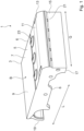
- the illustrated grate block 1 is used for the thermal treatment of waste as combustion material (not shown), which is moved or conveyed over the grate in a direction of movement B.
- the grate block 1 comprises a block body 3 with an upper wall 5 and side walls 6.
- the upper wall 5 comprises an outer support surface 7, which extends along a longitudinal axis L of the grate block 1 from a rear region 9 of the block body 3 in the direction of a front region 11 of the block body 3.
- the block body 3 comprises in the front region 11 a rounded overhang 13 (hereinafter referred to as nose), which connects the front region 11 to a front wall 15.
- a sliding surface 17 adjacent to the front wall 15 rests on the support surface 7 of another grate block (not shown).
- Thermally treated waste is transported in the direction of movement B by means of pushing movements carried out relative to one another.
- the sliding surfaces 17 slide on the support surfaces 7 of the grate blocks arranged underneath (not shown).
- the relative pushing movements are carried out along the longitudinal axis L and driven by a drive device (not shown), which Movement is transmitted to the block body via a holder 19.
- several grate blocks can lie next to one another, so that the side walls 6 of the grate block 1 border on the side walls of other grate blocks.
- the block body 3 comprises air supply openings 21, 23 which are arranged in the front wall 15 and the upper wall 5 and through which the thermally treated waste can be supplied with air to promote combustion. Embodiments which do not have air supply openings are also conceivable, but are not shown here.
- the air supply openings 23 in the upper wall 5 are preferably designed as passages which widen downwards, so that parts of the waste to be treated do not get caught in the opening if they pass through.
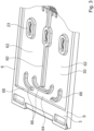
- the block body 3 further comprises a flat hollow space 50.
- the flat cavity 50 is delimited opposite the upper wall 5 of the block body 3 by a base 51 and a base plate 53.
- the cavity 50 further comprises a fluid supply line 52 and a fluid discharge line 54, which are each connected to a chamber 56.
- the chamber 56 extends essentially parallel to the front wall 15 ( Fig. 1 ) and is connected to the flat cavity 50 via inflow openings 58.
- the flat cavity 50 further comprises a partition wall 60, which extends from the front wall (reference number 15 in Fig. 1 ) towards a rear wall 68 ( Fig. 3 ) and forms a passage 64 so that the cavity 50 is divided into two compartments 62.
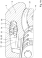
- Fig. 3 shows a view from below of a section through the grate block 1 from Fig. 1 in connection with the Fig. 2 described flat cavity 50.
- the base plate 53 made of Fig. 2 which delimits the cavity 50, has been removed here.
- the flat cavity 50 comprises deflection elements 66, which direct the fluid flow from the fluid supply line 52 ( Fig. 2 ) to the fluid drain line 54 ( Fig. 2 ) redirect.
- Fig. 3 It is also clearly visible how the flat cavity 50 in the rear area 9 of the block body 3 is delimited by the side walls 6 and the rear wall 68.
- Fig. 3 clearly visible that the air supply openings 23 pass from the upper wall through the flat cavity 50.
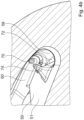
- Fig. 4a and 4b show a longitudinal section along the longitudinal axis L through the front area of the block body from Fig. 1 with the air supply openings 21 in the front wall 15.
- the partition wall 60 which divides the cavity 50, has an opening 70, which serves to ventilate the compartments 62 created by the partition wall 60.
- the inflow opening 58 comprises a distribution element 74 in an opening area 72 facing the cavity 50, which is designed here as a hump-like or hill-like obstacle.
- the fluid flow which is guided into the cavity 50 via the inflow opening 58, is distributed using the distribution element 74, so that no turbulences form within the flat cavity 50, which could lead to foam formation or air bubbles and thus to a reduced cooling performance.
- the bottom 51 limits the cavity 50 at the bottom.
- the bottom plate 53 made of Fig. 2 , which would be connected to the ground in the longitudinal direction L.
- the distribution element 74 could also be designed as a crossbar instead of the hump- or hill-like obstacle (not shown).
- Figure 5 shows a cross section through the front wall 15 with the Fig. 2 shown chambers 56, into which the fluid supply line 52 and the fluid discharge line 54 open.
- the cooling fluid flows through the fluid supply line 52 into the chamber 56 and is distributed via the inflow openings 58 in the cavity (not shown). After passing through the cavity, the cooling fluid flows through the inflow openings 58' into the chamber 56' and exits the block body 3 through the fluid discharge line 54.
- the fluid discharge line 54 can be connected to a further fluid supply line of a further block body (not shown).
- the block bodies shown have a length in the longitudinal direction L of 400 - 800 mm, preferably 500 - 750 mm and particularly preferably 650 - 700 mm.
- the block bodies shown have a width in the width direction Q of 280 - 500 mm, preferably 320 - 460 mm and particularly preferably 380 - 420 mm.
- the block bodies shown have a height of 100 - 200 mm, preferably 130 - 180 mm and particularly preferably 150 - 160 mm.
- the block body is preferably made of low-alloy to high-alloy cast steel.
- low-alloy to high-alloy cast steel also contains alloying elements such as chromium, nickel, Molybdenum, vanadium, tungsten and others.
- the block body is preferably manufactured by means of a casting or injection molding process.
- the inflow openings preferably have a diameter of 12 - 28 mm and particularly preferably a diameter of 16 - 22 mm.
- Figure 6 shows a longitudinal section along the longitudinal axis L through the block body 3 from Fig. 1 , whereby the distribution element in a front region 76 of the cavity 50 is not shown.
- the base 51 is designed as an integral part of the block body 3 and, together with the base plate 53, delimits the cavity 50 downwards.
- the cavity 50 is further delimited by the rear wall 68 and the front wall 15.
- the base plate 53 has the air supply openings 21 analogously to the upper wall 5.
- the air supply openings 21 widen from the upper wall 5 concentrically towards the base plate 53.
Landscapes
- Engineering & Computer Science (AREA)
- Mechanical Engineering (AREA)
- General Engineering & Computer Science (AREA)
- Chemical & Material Sciences (AREA)
- Combustion & Propulsion (AREA)
- Environmental & Geological Engineering (AREA)
- Incineration Of Waste (AREA)
- Tunnel Furnaces (AREA)
- Furnace Charging Or Discharging (AREA)
Claims (15)
- Bloc de grille refroidi (1) en tant que partie d'une grille pour une installation de traitement thermique de déchets, dans lequel les blocs de grille sont disposés les uns au-dessus des autres à la manière d'un escalier et sont conçus de telle sorte qu'au moyen de mouvements de poussée exécutés les uns par rapport aux autres, le produit à brûler est réarrangé et transporté pendant la combustion, comprenantun corps de bloc (3) réalisé sous forme de pièce coulée avec une paroi supérieure (5) qui forme une surface d'appui extérieure (7) pour les déchets à traiter, s'étendant au moins partiellement parallèlement à un axe longitudinal (L) du corps de bloc (1),une cavité plane (50) disposée directement en dessous de la surface d'appui (7) pour recevoir un fluide de refroidissement, qui est délimitée du côté supérieur par la paroi supérieure (5), du côté frontal par une paroi avant (15), du côté inférieur par un fond (51), du côté arrière par une paroi arrière (68) et latéralement par des parois latérales (6), le fond (51) étant formé au moins partiellement par une plaque de fond (53),un conduit d'alimentation en fluide (52) et un conduit d'évacuation de fluide (54), qui sont reliés à la cavité (50),au moins un élément de déviation (66) disposé dans la cavité (50) pour diriger un fluide de refroidissement dans la cavité (50) depuis la conduite d'alimentation en fluide (52) vers la conduite d'évacuation de fluide (54), etun élément de distribution (74) disposé dans une zone frontale (76) de la cavité (50) pour distribuer le fluide alimenté dans la cavité (50) par la conduite d'alimentation en fluide (52),caractérisé en ce que la conduite d'alimentation en fluide (52) et la conduite d'évacuation de fluide (54) sont reliées à la cavité plane (50) au niveau de la paroi avant (15).
- Bloc de grille selon la revendication 1, caractérisé en ce que l'élément de distribution (74) s'étend au moins par sections le long d'un axe latéral (Q) qui est au moins approximativement parallèle à la paroi avant (15).
- Bloc de grille selon l'une des revendications 1, caractérisé en ce que la cavité plane(50) est reliée à une chambre frontale (56) qui s'étend sensiblement parallèlement à la paroi avant (15) et par laquelle s'effectue l'arrivée du fluide de refroidissement dans la cavité plane(50) ou l'évacuation du fluide de refroidissement hors de la cavité (50).
- Bloc de grille selon l'une des revendications 3, caractérisé en ce que la cavité plane (50) et la chambre (56) sont reliées entre elles par plusieurs ouvertures d'alimentation (58).
- Bloc de grille selon l'une des revendications 1, caractérisé en ce que la cavité plane (50) présente une paroi de séparation (60) s'étendant du fond (51) à la paroi supérieure (5), qui s'étend de la paroi avant (15) en direction de la paroi arrière (68) de la cavité (50), forme un passage (64) dans la zone de la paroi arrière (68) et divise la cavité (50) en deux compartiments (62) reliés par conduction de fluide
- Bloc de grille selon la revendication 5, caractérisé en ce que la paroi de séparation (60) présente, dans la zone de la paroi avant, une ouverture (70) pour l'aération de la cavité (50) ou des compartiments (62) créés par la paroi de séparation (60).
- Bloc de grille selon l'une des revendications 5 ou 6, caractérisé en ce que la paroi de séparation (60) est au moins approximativement parallèle à l'une des parois latérales (6).
- Bloc de grille selon l'une des revendications 1 à 7, caractérisé en ce que l'élément de distribution (74) se présente de préférence sous la forme d'un bossage, d'un écran, d'une plaque perforée ou d'une barre transversale, qui s'étend au moins approximativement parallèlement à la paroi avant (15) .
- Bloc de grille selon l'une des revendications 4 à 8, caractérisé en ce que l'élément de distribution (74) se trouve dans une zone d'embouchure (72) d'au moins l'un des ouvertures d'alimentation (58).
- Bloc de grille selon l'une quelconque des revendications 1 à 9, caractérisé en ce que l'élément de distribution (74) comprend une saillie en forme de tremplin ou de colline qui limite ou dévie l'écoulement du fluide de refroidissement provenant de la conduite d'alimentation en fluide (52) .
- Bloc de grille selon l'une quelconque des revendications 1 à 10, caractérisé en ce que l'élément de distribution (74) est conçu pour permettre uniquement un écoulement limité de fluide de refroidissement devant l'élément de distribution (74) afin de permettre une distribution uniforme du fluide de refroidissement à l'intérieur de la cavité (50) .
- Bloc de grille selon l'une des revendications 1 à 11, caractérisé en ce que la paroi supérieure (5) et/ou la paroi avant (15) comporte au moins une ouverture d'alimentation en air (21, 23).
- Bloc de grille selon l'une des revendications 1 à 12, caractérisé en ce que le corps de bloc (3) est fabriqué d'une seule pièce en tant que pièce coulée et la plaque de fond (53) est de préférence soudée au corps de bloc (3) pour délimiter la cavité (50).
- Bloc de grille selon l'une des revendications 1 à 13, caractérisé en ce que la cavité (50) s'étend sur au moins 2/3 de la longueur et/ou sur au moins 3/4 de la largeur de la surface d'appui (7).
- Grille comprenant plusieurs blocs de grille selon l'une quelconque des revendications 1 à 14.
Priority Applications (1)
| Application Number | Priority Date | Filing Date | Title |
|---|---|---|---|
| EP24210864.5A EP4477948A3 (fr) | 2020-09-09 | 2021-09-09 | Bloc de grille refroidi par eau pour un incinérateur |
Applications Claiming Priority (2)
| Application Number | Priority Date | Filing Date | Title |
|---|---|---|---|
| EP20195293.4A EP3967927B1 (fr) | 2020-09-09 | 2020-09-09 | Bloc de grille refroidi par eau pour une installation d'incinération |
| PCT/EP2021/074784 WO2022053550A1 (fr) | 2020-09-09 | 2021-09-09 | Bloc de grille refroidi par eau pour incinérateur |
Related Child Applications (2)
| Application Number | Title | Priority Date | Filing Date |
|---|---|---|---|
| EP24210864.5A Division EP4477948A3 (fr) | 2020-09-09 | 2021-09-09 | Bloc de grille refroidi par eau pour un incinérateur |
| EP24210864.5A Division-Into EP4477948A3 (fr) | 2020-09-09 | 2021-09-09 | Bloc de grille refroidi par eau pour un incinérateur |
Publications (3)
| Publication Number | Publication Date |
|---|---|
| EP4211397A1 EP4211397A1 (fr) | 2023-07-19 |
| EP4211397B1 true EP4211397B1 (fr) | 2025-01-08 |
| EP4211397C0 EP4211397C0 (fr) | 2025-01-08 |
Family
ID=72470170
Family Applications (3)
| Application Number | Title | Priority Date | Filing Date |
|---|---|---|---|
| EP20195293.4A Active EP3967927B1 (fr) | 2020-09-09 | 2020-09-09 | Bloc de grille refroidi par eau pour une installation d'incinération |
| EP24210864.5A Pending EP4477948A3 (fr) | 2020-09-09 | 2021-09-09 | Bloc de grille refroidi par eau pour un incinérateur |
| EP21777426.4A Active EP4211397B1 (fr) | 2020-09-09 | 2021-09-09 | Bloc de grille refroidi par eau pour une installation d'incinération |
Family Applications Before (2)
| Application Number | Title | Priority Date | Filing Date |
|---|---|---|---|
| EP20195293.4A Active EP3967927B1 (fr) | 2020-09-09 | 2020-09-09 | Bloc de grille refroidi par eau pour une installation d'incinération |
| EP24210864.5A Pending EP4477948A3 (fr) | 2020-09-09 | 2021-09-09 | Bloc de grille refroidi par eau pour un incinérateur |
Country Status (9)
| Country | Link |
|---|---|
| US (1) | US20230332769A1 (fr) |
| EP (3) | EP3967927B1 (fr) |
| JP (1) | JP2023540142A (fr) |
| AU (1) | AU2021339933A1 (fr) |
| CA (1) | CA3191998A1 (fr) |
| ES (2) | ES2987363T3 (fr) |
| MX (1) | MX2023002697A (fr) |
| PL (2) | PL3967927T3 (fr) |
| WO (1) | WO2022053550A1 (fr) |
Families Citing this family (1)
| Publication number | Priority date | Publication date | Assignee | Title |
|---|---|---|---|---|
| FI20215661A1 (fi) * | 2021-06-07 | 2022-12-08 | Ariterm Service Oy | Nestejäähdytteinen arina kiinteän polttoaineen polttimessa |
Family Cites Families (15)
| Publication number | Priority date | Publication date | Assignee | Title |
|---|---|---|---|---|
| JPH02106613A (ja) * | 1988-10-13 | 1990-04-18 | Hitachi Zosen Corp | 焼却炉の火格子構造 |
| CH684118A5 (de) * | 1993-04-20 | 1994-07-15 | Doikos Investments Ltd | Verfahren zum Verbrennen von Kehricht auf einem Verbrennungsrost sowie Verbrennungsrost zur Ausübung des Verfahrens und Rostplatte für einen solchen Verbrennungsrost. |
| DE4400992C1 (de) * | 1994-01-14 | 1995-05-11 | Noell Abfall & Energietech | Roststab und Rost mit Kühleinrichtung |
| WO1996029544A1 (fr) * | 1995-03-23 | 1996-09-26 | Theodor Koch | Grille de combustion et procede d'optimisation du fonctionnement d'une grille de combustion |
| DE19622424C2 (de) | 1996-06-04 | 1998-10-29 | Martin Umwelt & Energietech | Rostelement und Rost mit Flüssigkeitskühlung |
| EP0989364B1 (fr) * | 1998-09-24 | 2000-04-26 | Von Roll Umwelttechnik AG | Elément de grille et procédé de refroidissement de ce dernier |
| WO2002021049A1 (fr) | 2000-09-04 | 2002-03-14 | Theodor Koch | Barreau de grille a refroidissement par du liquide pour des incinerateurs |
| ATE237784T1 (de) * | 2000-09-22 | 2003-05-15 | Von Roll Umwelttechnik Ag | Gekühlter rostblock |
| PL1760400T3 (pl) | 2005-09-06 | 2009-08-31 | Ernst Schenkel | Chłodzony wodą element rusztu |
| US10180254B2 (en) * | 2014-09-16 | 2019-01-15 | Hitachi Zosen Inova Ag | Method and device for processing slag occurring in a combustion chamber of a refuse incineration plant |
| DE102015101356B4 (de) | 2015-01-30 | 2025-11-13 | Standardkessel Baumgarte Service GmbH | Roststab mit Kühlmittel-Kanal |
| KR101560714B1 (ko) * | 2015-05-26 | 2015-10-16 | 지이큐솔루션 주식회사 | 수냉식화격자 제작방법 및 이에 의해 제작된 수냉식화격자 |
| KR101701720B1 (ko) * | 2016-06-20 | 2017-02-03 | 지이큐솔루션 주식회사 | 수냉식 화격자 및 수냉식 화격자용 스토커를 구비한 소각로 |
| US10309648B2 (en) * | 2016-11-22 | 2019-06-04 | General Electric Company | System and method for active cooling of a grate bar for an incinerator of a waste-to-energy plant |
| KR102110167B1 (ko) * | 2018-12-19 | 2020-05-13 | 지이큐솔루션 주식회사 | 연소공기 토출구를 분할배치시켜 바이오매스 연소속도에 대응하는 수냉 및 공냉 일체형 화격자 |
-
2020
- 2020-09-09 ES ES20195293T patent/ES2987363T3/es active Active
- 2020-09-09 EP EP20195293.4A patent/EP3967927B1/fr active Active
- 2020-09-09 PL PL20195293.4T patent/PL3967927T3/pl unknown
-
2021
- 2021-09-09 US US18/025,418 patent/US20230332769A1/en active Pending
- 2021-09-09 CA CA3191998A patent/CA3191998A1/fr active Pending
- 2021-09-09 JP JP2023515636A patent/JP2023540142A/ja active Pending
- 2021-09-09 EP EP24210864.5A patent/EP4477948A3/fr active Pending
- 2021-09-09 PL PL21777426.4T patent/PL4211397T3/pl unknown
- 2021-09-09 WO PCT/EP2021/074784 patent/WO2022053550A1/fr not_active Ceased
- 2021-09-09 MX MX2023002697A patent/MX2023002697A/es unknown
- 2021-09-09 EP EP21777426.4A patent/EP4211397B1/fr active Active
- 2021-09-09 AU AU2021339933A patent/AU2021339933A1/en active Pending
- 2021-09-09 ES ES21777426T patent/ES3014401T3/es active Active
Also Published As
| Publication number | Publication date |
|---|---|
| WO2022053550A1 (fr) | 2022-03-17 |
| US20230332769A1 (en) | 2023-10-19 |
| PL4211397T3 (pl) | 2025-04-28 |
| EP4477948A2 (fr) | 2024-12-18 |
| EP3967927A1 (fr) | 2022-03-16 |
| MX2023002697A (es) | 2023-05-24 |
| ES3014401T3 (en) | 2025-04-22 |
| PL3967927T3 (pl) | 2024-11-04 |
| EP3967927C0 (fr) | 2024-07-03 |
| EP3967927B1 (fr) | 2024-07-03 |
| AU2021339933A1 (en) | 2023-03-02 |
| EP4477948A3 (fr) | 2025-03-12 |
| JP2023540142A (ja) | 2023-09-21 |
| ES2987363T3 (es) | 2024-11-14 |
| EP4211397C0 (fr) | 2025-01-08 |
| EP4211397A1 (fr) | 2023-07-19 |
| CA3191998A1 (fr) | 2022-03-17 |
Similar Documents
| Publication | Publication Date | Title |
|---|---|---|
| EP0757206B1 (fr) | Grille pour un foyer | |
| DE102009016577B4 (de) | Verfahren zum Betrieb einer Batteriekühlplatte | |
| DE2835854C2 (de) | Schlackenrinne für Hochöfen | |
| DE4105330C1 (fr) | ||
| DE2804106C2 (de) | Wärmetauscher | |
| EP0537523A1 (fr) | Refroidisseur à grilles | |
| EP4211397B1 (fr) | Bloc de grille refroidi par eau pour une installation d'incinération | |
| DE69602906T2 (de) | Giessrohr zum Einleiten eines flüssigen Metalles in einer Stranggiesskokille zum Giessen metallischer Produkte mit diesem ausgerüstete Stranggiessvorrichtung | |
| WO2012104111A1 (fr) | Barreau de grille | |
| LU85119A1 (de) | Fluessigkeitsgekuehlte metallische abstichrinne | |
| DE3230597C1 (de) | Roststab fuer Rostbelaege,insbesondere von Feuerungen | |
| DE102015101356B4 (de) | Roststab mit Kühlmittel-Kanal | |
| EP2184540B1 (fr) | Bloc de grille à refroidissement par air | |
| WO1999032831A1 (fr) | Barreau de grille pour grille de combustion et procede pour son refroidissement | |
| EP3994393B1 (fr) | Bloc de grillage pour une grille de combustion | |
| EP1760400B1 (fr) | Elément de grille avec refroidissement à liquide | |
| DE3149548C2 (de) | Rost für eine Feuerungsanlage | |
| DE29707180U1 (de) | Schachtkühler | |
| EP3967926B1 (fr) | Bloc de grillage pourvu de nez montant | |
| EP3023694B1 (fr) | Barreau de grille et grille pour un foyer a grille | |
| EP1191282A1 (fr) | Barreau de grille refroidi | |
| EP4253840B1 (fr) | Grille de combustion et unité de combustion | |
| DE69702002T2 (de) | Vorrichtung und verfahren zum metallschmelzen | |
| DE19860553A1 (de) | Flüssigkeitsgekühlter Verbrennungsrost | |
| DE29618460U1 (de) | Schachtkühler |
Legal Events
| Date | Code | Title | Description |
|---|---|---|---|
| STAA | Information on the status of an ep patent application or granted ep patent |
Free format text: STATUS: UNKNOWN |
|
| STAA | Information on the status of an ep patent application or granted ep patent |
Free format text: STATUS: THE INTERNATIONAL PUBLICATION HAS BEEN MADE |
|
| PUAI | Public reference made under article 153(3) epc to a published international application that has entered the european phase |
Free format text: ORIGINAL CODE: 0009012 |
|
| STAA | Information on the status of an ep patent application or granted ep patent |
Free format text: STATUS: REQUEST FOR EXAMINATION WAS MADE |
|
| 17P | Request for examination filed |
Effective date: 20230328 |
|
| AK | Designated contracting states |
Kind code of ref document: A1 Designated state(s): AL AT BE BG CH CY CZ DE DK EE ES FI FR GB GR HR HU IE IS IT LI LT LU LV MC MK MT NL NO PL PT RO RS SE SI SK SM TR |
|
| DAV | Request for validation of the european patent (deleted) | ||
| DAX | Request for extension of the european patent (deleted) | ||
| GRAP | Despatch of communication of intention to grant a patent |
Free format text: ORIGINAL CODE: EPIDOSNIGR1 |
|
| STAA | Information on the status of an ep patent application or granted ep patent |
Free format text: STATUS: GRANT OF PATENT IS INTENDED |
|
| INTG | Intention to grant announced |
Effective date: 20240730 |
|
| GRAS | Grant fee paid |
Free format text: ORIGINAL CODE: EPIDOSNIGR3 |
|
| RAP3 | Party data changed (applicant data changed or rights of an application transferred) |
Owner name: KANADEVIA INOVA AG |
|
| GRAA | (expected) grant |
Free format text: ORIGINAL CODE: 0009210 |
|
| STAA | Information on the status of an ep patent application or granted ep patent |
Free format text: STATUS: THE PATENT HAS BEEN GRANTED |
|
| AK | Designated contracting states |
Kind code of ref document: B1 Designated state(s): AL AT BE BG CH CY CZ DE DK EE ES FI FR GB GR HR HU IE IS IT LI LT LU LV MC MK MT NL NO PL PT RO RS SE SI SK SM TR |
|
| REG | Reference to a national code |
Ref country code: GB Ref legal event code: FG4D Free format text: NOT ENGLISH |
|
| REG | Reference to a national code |
Ref country code: CH Ref legal event code: EP |
|
| REG | Reference to a national code |
Ref country code: DE Ref legal event code: R096 Ref document number: 502021006374 Country of ref document: DE |
|
| REG | Reference to a national code |
Ref country code: IE Ref legal event code: FG4D Free format text: LANGUAGE OF EP DOCUMENT: GERMAN |
|
| U01 | Request for unitary effect filed |
Effective date: 20250114 |
|
| U07 | Unitary effect registered |
Designated state(s): AT BE BG DE DK EE FI FR IT LT LU LV MT NL PT RO SE SI Effective date: 20250120 |
|
| REG | Reference to a national code |
Ref country code: ES Ref legal event code: FG2A Ref document number: 3014401 Country of ref document: ES Kind code of ref document: T3 Effective date: 20250422 |
|
| REG | Reference to a national code |
Ref country code: GR Ref legal event code: EP Ref document number: 20250400477 Country of ref document: GR Effective date: 20250409 |
|
| PG25 | Lapsed in a contracting state [announced via postgrant information from national office to epo] |
Ref country code: RS Free format text: LAPSE BECAUSE OF FAILURE TO SUBMIT A TRANSLATION OF THE DESCRIPTION OR TO PAY THE FEE WITHIN THE PRESCRIBED TIME-LIMIT Effective date: 20250408 |
|
| PG25 | Lapsed in a contracting state [announced via postgrant information from national office to epo] |
Ref country code: IS Free format text: LAPSE BECAUSE OF FAILURE TO SUBMIT A TRANSLATION OF THE DESCRIPTION OR TO PAY THE FEE WITHIN THE PRESCRIBED TIME-LIMIT Effective date: 20250508 |
|
| PG25 | Lapsed in a contracting state [announced via postgrant information from national office to epo] |
Ref country code: HR Free format text: LAPSE BECAUSE OF FAILURE TO SUBMIT A TRANSLATION OF THE DESCRIPTION OR TO PAY THE FEE WITHIN THE PRESCRIBED TIME-LIMIT Effective date: 20250108 |
|
| REG | Reference to a national code |
Ref country code: CH Ref legal event code: U11 Free format text: ST27 STATUS EVENT CODE: U-0-0-U10-U11 (AS PROVIDED BY THE NATIONAL OFFICE) Effective date: 20251001 |
|
| PG25 | Lapsed in a contracting state [announced via postgrant information from national office to epo] |
Ref country code: SM Free format text: LAPSE BECAUSE OF FAILURE TO SUBMIT A TRANSLATION OF THE DESCRIPTION OR TO PAY THE FEE WITHIN THE PRESCRIBED TIME-LIMIT Effective date: 20250108 |
|
| PGFP | Annual fee paid to national office [announced via postgrant information from national office to epo] |
Ref country code: NO Payment date: 20250923 Year of fee payment: 5 Ref country code: GR Payment date: 20250922 Year of fee payment: 5 |
|
| PGFP | Annual fee paid to national office [announced via postgrant information from national office to epo] |
Ref country code: TR Payment date: 20250902 Year of fee payment: 5 Ref country code: PL Payment date: 20250829 Year of fee payment: 5 |
|
| PGFP | Annual fee paid to national office [announced via postgrant information from national office to epo] |
Ref country code: GB Payment date: 20250919 Year of fee payment: 5 |
|
| PGFP | Annual fee paid to national office [announced via postgrant information from national office to epo] |
Ref country code: IE Payment date: 20250918 Year of fee payment: 5 Ref country code: CZ Payment date: 20250903 Year of fee payment: 5 |
|
| U20 | Renewal fee for the european patent with unitary effect paid |
Year of fee payment: 5 Effective date: 20250917 |
|
| PG25 | Lapsed in a contracting state [announced via postgrant information from national office to epo] |
Ref country code: SK Free format text: LAPSE BECAUSE OF FAILURE TO SUBMIT A TRANSLATION OF THE DESCRIPTION OR TO PAY THE FEE WITHIN THE PRESCRIBED TIME-LIMIT Effective date: 20250108 |
|
| PLBE | No opposition filed within time limit |
Free format text: ORIGINAL CODE: 0009261 |
|
| STAA | Information on the status of an ep patent application or granted ep patent |
Free format text: STATUS: NO OPPOSITION FILED WITHIN TIME LIMIT |