EP4209367B1 - Verfahren zum auslösen eines rtr-ventils, steuergerät, druckluftsystem und anhängefahrzeug - Google Patents
Verfahren zum auslösen eines rtr-ventils, steuergerät, druckluftsystem und anhängefahrzeug Download PDFInfo
- Publication number
- EP4209367B1 EP4209367B1 EP22211841.6A EP22211841A EP4209367B1 EP 4209367 B1 EP4209367 B1 EP 4209367B1 EP 22211841 A EP22211841 A EP 22211841A EP 4209367 B1 EP4209367 B1 EP 4209367B1
- Authority
- EP
- European Patent Office
- Prior art keywords
- valve
- rtr
- reservoir
- pressure
- electrical pulse
- Prior art date
- Legal status (The legal status is an assumption and is not a legal conclusion. Google has not performed a legal analysis and makes no representation as to the accuracy of the status listed.)
- Active
Links
Images

Classifications
-
- B—PERFORMING OPERATIONS; TRANSPORTING
- B60—VEHICLES IN GENERAL
- B60G—VEHICLE SUSPENSION ARRANGEMENTS
- B60G17/00—Resilient suspensions having means for adjusting the spring or vibration-damper characteristics, for regulating the distance between a supporting surface and a sprung part of vehicle or for locking suspension during use to meet varying vehicular or surface conditions, e.g. due to speed or load
- B60G17/02—Spring characteristics, e.g. mechanical springs and mechanical adjusting means
- B60G17/04—Spring characteristics, e.g. mechanical springs and mechanical adjusting means fluid spring characteristics
- B60G17/052—Pneumatic spring characteristics
- B60G17/0523—Regulating distributors or valves for pneumatic springs
- B60G17/0525—Height adjusting or levelling valves
-
- B—PERFORMING OPERATIONS; TRANSPORTING
- B60—VEHICLES IN GENERAL
- B60G—VEHICLE SUSPENSION ARRANGEMENTS
- B60G17/00—Resilient suspensions having means for adjusting the spring or vibration-damper characteristics, for regulating the distance between a supporting surface and a sprung part of vehicle or for locking suspension during use to meet varying vehicular or surface conditions, e.g. due to speed or load
- B60G17/005—Suspension locking arrangements
-
- B—PERFORMING OPERATIONS; TRANSPORTING
- B60—VEHICLES IN GENERAL
- B60G—VEHICLE SUSPENSION ARRANGEMENTS
- B60G2202/00—Indexing codes relating to the type of spring, damper or actuator
- B60G2202/10—Type of spring
- B60G2202/15—Fluid spring
- B60G2202/152—Pneumatic spring
-
- B—PERFORMING OPERATIONS; TRANSPORTING
- B60—VEHICLES IN GENERAL
- B60G—VEHICLE SUSPENSION ARRANGEMENTS
- B60G2204/00—Indexing codes related to suspensions per se or to auxiliary parts
- B60G2204/40—Auxiliary suspension parts; Adjustment of suspensions
- B60G2204/46—Means for locking the suspension
-
- B—PERFORMING OPERATIONS; TRANSPORTING
- B60—VEHICLES IN GENERAL
- B60G—VEHICLE SUSPENSION ARRANGEMENTS
- B60G2300/00—Indexing codes relating to the type of vehicle
- B60G2300/04—Trailers
-
- B—PERFORMING OPERATIONS; TRANSPORTING
- B60—VEHICLES IN GENERAL
- B60G—VEHICLE SUSPENSION ARRANGEMENTS
- B60G2400/00—Indexing codes relating to detected, measured or calculated conditions or factors
- B60G2400/20—Speed
- B60G2400/204—Vehicle speed
-
- B—PERFORMING OPERATIONS; TRANSPORTING
- B60—VEHICLES IN GENERAL
- B60G—VEHICLE SUSPENSION ARRANGEMENTS
- B60G2400/00—Indexing codes relating to detected, measured or calculated conditions or factors
- B60G2400/25—Stroke; Height; Displacement
- B60G2400/252—Stroke; Height; Displacement vertical
-
- B—PERFORMING OPERATIONS; TRANSPORTING
- B60—VEHICLES IN GENERAL
- B60G—VEHICLE SUSPENSION ARRANGEMENTS
- B60G2500/00—Indexing codes relating to the regulated action or device
- B60G2500/30—Height or ground clearance
-
- B—PERFORMING OPERATIONS; TRANSPORTING
- B60—VEHICLES IN GENERAL
- B60G—VEHICLE SUSPENSION ARRANGEMENTS
- B60G2600/00—Indexing codes relating to particular elements, systems or processes used on suspension systems or suspension control systems
- B60G2600/02—Retarders, delaying means, dead zones, threshold values, cut-off frequency, timer interruption
Definitions
- the invention also relates to a control device, a compressed air system and a trailer vehicle.
- an adjusting lever that can be moved by an operator can be moved back and forth between these positions.
- the height of the vehicle body can be adjusted to external conditions, for example to the level of a loading ramp or a rail transport that has to be carried out with the vehicle body lowered.
- the RtR valve When driving, the RtR valve should be in the drive position. Only in the drive position does the RtR valve enable automatic level compensation using a normally provided air suspension valve.
- the RtR valve can remain in the four positions outside the driving position. It must therefore be ensured that a condition-dependent return to the driving position is possible.
- the RtR valve is specially designed and can be controlled by a control unit. Once the trailer vehicle exceeds a certain minimum speed, the RtR valve automatically switches to the driving position. This is where the name of the valve comes from. RtR means "Return to Ride” or "Reset to Ride”.
- a component of the RtR valve is a locking device for the control lever.
- the control lever is subjected to a restoring force outside of the driving position.
- the locking device holds the control lever in position in such a way that the control lever can still be adjusted by the operator, but cannot automatically return to the driving position.
- the The locking device must be released, which is referred to here as the RtR valve being triggered.
- the triggering takes place electro-pneumatically after the minimum speed is exceeded.
- the supply of compressed air to an actuating cylinder of the locking device is controlled by a solenoid valve that can be controlled by an electrical pulse. As soon as compressed air is supplied, the effect of the locking device is canceled and the RtR valve is triggered.
- the actuating lever can automatically return to the driving position if it was previously in a non-driving position.
- RtR valve with the functions mentioned above is, for example, Fig.1 the EP 3 643 543 B1
- the RtR valve is referred to in the associated description as "valve device 1", the locking device as “locking valve 32" and "return-to-ride valve 33".
- the function of the locking device in connection with a RtR valve is also in Fig. 2 and 3 the EN 10 2010 011 433 A1
- the RtR valve is referred to in the associated description as “valve device 6" and the locking device as "locking device 30".
- the trailer vehicle has two reservoirs for compressed air, namely a reservoir for the braking system and a reservoir for the air suspension system or other auxiliary consumers. If the air reservoirs are empty, the air reservoir for the braking system is first filled via a supply line from the towing vehicle. As soon as this has reached an overflow pressure, the air reservoir for the air suspension system is also filled.
- the RtR valve is not in the driving position and at least the reservoir for the air suspension is depressurised, undesirable or even dangerous situations can occur when driving off.
- the trailer is connected to the towing vehicle and set in motion. If a minimum speed is exceeded, the RtR valve is triggered by a control unit briefly controlled with an electrical pulse. Due to a lack of pressure in the reservoir, no compressed air is supplied to the locking device in the RtR valve to unlock it. The RtR valve is then not triggered and does not return to its driving position.
- the vehicle body remains, for example, in the maximum raised or maximum lowered position.
- the object of the present invention is to ensure that the driving position is assumed.
- the method according to the invention has the features of claim 1.
- the RtR valve is triggered depending on the minimum speed and on a supply pressure in the brake system.
- the supply pressure in the brake system is also the pressure in the reservoir of the brake system and is monitored anyway for other reasons and is therefore present. If the supply pressure in the brake system is stable or relatively high over a period of time, it can be assumed that there is sufficient pressure in the reservoir for the air suspension system to trigger it.
- the minimum speed is preferably 10 km/h to 30 km/h, in particular 30 km/h.
- the electrical pulse is repeated until the reservoir pressure in the brake system exceeds a defined limit value.
- the reservoir pressure in the brake system is compared with the defined limit value. The repetition of the pulse ensures that the system is triggered. At the same time, excessive heating of the electromagnetic components involved can be avoided.
- the limit value is exceeded, the specified process steps are carried out.
- the defined limit value should be selected so that the reservoir for the air suspension system also has a minimum pressure in parallel with the reservoir for the brake system, although the filling of the reservoir for the air suspension system does not have to be completed yet.
- the electrical pulse is maintained until the reservoir pressure in the brake system exceeds a defined limit. Maintaining the pulse also ensures triggering. At the same time, triggering occurs immediately after the condition is met and is not delayed by a pause between pulses.
- the RtR valve is only activated by the electrical pulse when, in addition to reaching the minimum speed, the reservoir pressure in the brake system exceeds a defined limit. The activation takes place without delay, the electrical pulse can be relatively short and does not have to be repeated.
- the overflow pressure is a parameter of the combination of braking system and air suspension system and is therefore known.
- the pressure difference is added to the overflow pressure to calculate the limit value and can be determined empirically or from characteristics of the RtR valve.
- the pressure difference is 0.2 bar to 1.3 bar, in particular 0.4 bar to 1 bar, in particular 0.5 bar.
- the specified ranges and numerical values have proven to be advantageous in tests. This also takes into account the properties of the locking device in the RtR valve, including restoring or holding forces which counteract the pneumatic unlocking of the locking device.
- the electrical pulse is repeated with a pulse interval of 10 seconds to 20 seconds, in particular with a pulse interval of 15 seconds.
- a sufficiently large pulse interval prevents excessive heating of a solenoid valve subjected to the electrical pulse.
- the pulse interval is the period between the start of a certain pulse and the start of the subsequent pulse.
- the pause between two electrical pulses should be between 5 seconds and 15 seconds, and in particular 10 seconds. This also prevents the components involved from becoming excessively hot.
- the electrical pulse has a pulse duration of 2 seconds to 10 seconds, in particular a pulse duration of 5 seconds.
- the pulse duration should be long enough to be able to trigger the RtR valve safely. At the same time, excessive heating of the solenoid valve controlled by the electrical pulse should be avoided.
- the invention also relates to a control device with the features of claim 13, including a computer program for carrying out the method according to the invention.
- the invention also relates to a compressed air system with the features of claim 14, including a control device according to the invention. Finally, the invention also relates to a trailer vehicle with the features of claim 15.
- Fig.1 and 2 show both the state of the art and the invention, depending on the configuration of an electronic control unit 10 in an air suspension system 11.
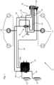
- FIG.1 the air suspension system 11 for a trailer vehicle with a pneumatic braking system and three axles is shown.
- the braking system and axles are not shown in detail.
- a reservoir 12 for the air suspension system, a reservoir 13 for the braking system, an air suspension valve 14, an RtR valve 15, air suspension bellows 16 on one side of the vehicle and air suspension bellows 17 on another side of the vehicle, as well as pneumatic lines 18, 19, an electrical line 20 and an electrical output 20a of the control unit 10 can be seen.
- a pressure sensor for detecting the pressure in the reservoir 13 of the braking system is present in the control unit 10 but is not shown separately. Also present but not shown separately are speed sensors from whose signals the control unit 10 can determine the speed. Alternatively, the control unit 10 can receive a speed signal from a towing vehicle via a line (not shown).
- Supply pressure is provided from the storage tank 12 via the pneumatic lines 18.
- the air suspension bellows 16, 17 are connected to the RtR valve 15 via the pneumatic lines 19 and indirectly to the air suspension valve 14.
- a rod 21 is shown, which is connected on the one hand to the air suspension valve 14 and a height sensor integrated therein and on the other hand to an axle (not shown) or another part of a chassis.
- the RtR valve 15 is internally designed in such a way that a Fig.1
- the adjusting lever 22 shown can be moved to a "lower” position and can engage there.
- the operator can release the adjusting lever 22 in the "lower” position while the air bellows 16, 17 continue to be deflated until the vehicle body is completely lowered, for example for rail transport of the trailer.
- Fig.1 the adjusting lever 22 is in a driving position. Between the driving position and the "lowering" position, the adjusting lever 22 can assume a stop position in which the previously lowered position of the vehicle body is maintained while the air suspension valve 14 remains blocked. The same applies to a stop position between the driving position and the "raising" position.
- the control unit 10 monitors the speed of the trailer vehicle and, when a previously defined minimum speed is reached, sends an electrical pulse E via the output 20a and the line 20 to the RtR valve 15, which then returns to the driving position.
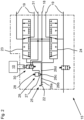
- the RtR valve 15 has its own multi-way valves 23, 24 internally for the air spring bellows 16, 17, in this case 4/5-way valves. These are adjusted by the adjusting lever 22.
- Part of an adjustment mechanism 25 connected to the adjusting lever 22 is a locking device 29 with a locking element 27 entering locking grooves 26a, 26b, 26c, 26d.
- the locking element 27 is loaded by a compression spring 28 and can be pneumatically lifted out of the locking grooves 26a, 26b, 26c, 26d against the force of the compression spring 28 so that unlocking takes place.
- the locking device 29 can be pneumatically controlled via a solenoid valve 30.
- the solenoid valve 30 receives the electrical pulse already mentioned above from the control unit 10 when the minimum speed is exceeded.
- the locking device 29 can be connected either to the supply pressure line 18 or to a vent 31 by adjusting the solenoid valve 30. As soon as supply pressure is applied, the locking device 29 is unlocked; when connected to the vent 31, the locking device 29 is effective.
- the Fig. 2 The circuit diagram shown is in a very similar form also in Fig.1 the EP 3 643 543 B1 with associated description. Reference is made to this for better understanding and as an optional supplement to the disclosure.
- the adjusting lever 22 is in the driving position, as well as in Fig.1 Accordingly, the locking element 27 is located in a locking groove 26c belonging to the driving position.
- the locking grooves 26b, 26d for stop positions are shown, on the far left the locking groove 26a for the "lower” position, exactly as in Fig.1 the EP 3 643 543 B1 A locking groove for the "lifting" position is not shown, but can be provided.
- the control unit 10 controls the triggering of the RtR valve 15 in a special way: In addition to the speed, the control unit 10 checks the supply pressure in the reservoir 13 for the brake system. If the reservoirs 12, 13 are completely empty, they are refilled one after the other via a supply line from the towing vehicle.
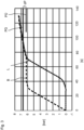
- the reservoir pressure curves are shown in Fig.3 shown.
- the reservoir 13 for the brake system is filled first, see coarsely dashed curve B. Only when the reservoir pressure in the reservoir 13 has exceeded a so-called overflow pressure PÜ of, for example, 6.2 bar, is the reservoir 12 for the air suspension system 11 also filled, see finely dashed curve L. After a certain time, here after about 70 seconds from the start of filling of the reservoir 13, the pressures in the two reservoirs 12, 13 increase to almost the same level until the full pressure of 7.5 bar or a similar pressure is reached.
- the locking device 29 is unlocked using the pressure in the reservoir 12 of the air suspension system.
- the control unit 10 controls the electrical pulse E several times until the reservoir pressure in the reservoir 13 of the brake system exceeds a limit value PG.
- the limit value PG is calculated from the overflow pressure PÜ plus a pressure difference dP.
- the pressure difference dP is preferably 0.5 bar, but can also deviate from this value upwards or downwards and is preferably between 0.2 bar and 1.3 bar.
- the upper right corner Fig. 3 Only a short line is drawn for the overflow pressure PÜ. This is not intended to represent a time limit or change in the overflow pressure PÜ.
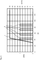
- the electrical pulse E can be limited in time and can be controlled repeatedly, see Fig.4
- the solid line v indicates the speed of the trailer, while the dashed line E represents the electrical pulses.
- Fig.4 Four electrical pulses E are emitted one after the other, starting from the minimum speed of 30 km/h and with short pauses between each electrical pulse E.
- Pulse interval a and pulse duration d are in Fig.5
- the pulse interval as the period between the beginning of two consecutive pulses E is 15 seconds, with a pulse duration of 5 seconds. Accordingly, the pauses are each 10 seconds.
- the last pulse E is controlled as long as the pressure B has not yet exceeded the limit PG, in the example of the Fig.4 at approximately 85 seconds after the start of filling of the storage containers 12, 13. As soon as the limit value PG is exceeded, no further pulse E is output.
- the first controlled electrical pulse E can be maintained until the limit value PG is exceeded.
- the electrical pulse E is only activated when the limit value PG is exceeded, again in conjunction with the minimum speed being exceeded.
Landscapes
- Engineering & Computer Science (AREA)
- Mechanical Engineering (AREA)
- Vehicle Body Suspensions (AREA)
Description
- Die Erfindung betrifft ein Verfahren zum elektropneumatischen Auslösen eines manuell betätigbaren RtR-Ventils in einem Anhängefahrzeug mit pneumatischer Bremsanlage und Luftfedersystem und mit getrennten Vorratsbehältern für die Bremsanlage und für das Luftfedersystem, wobei
- das RtR-Ventil durch das Auslösen aus einer Nicht-Fahrstellung in eine Fahrstellung zurückkehrt,
- Druckluft aus dem Vorratsbehälter für die Bremsanlage nur nach Erreichen eines Überströmdrucks in den Vorratsbehälter für das Luftfedersystem strömt und nur der Vorratsbehälter für das Luftfedersystem Druckluft zum Auslösen des RtR-Ventils zur Verfügung stellt,
- und das RtR-Ventil zum Auslösen desselben durch einen elektrischen Puls angesteuert wird, wenn das Fahrzeug bei zunehmender Geschwindigkeit eine Mindestgeschwindigkeit erreicht hat.
- Daneben betrifft die Erfindung ein Steuergerät, ein Druckluftsystem und ein Anhängefahrzeug.
- Anhängefahrzeuge mit pneumatischer Bremsanlage und Luftfedersystem können ein sogenanntes RtR-Ventil aufweisen. Dieses wird manuell betätigt und ist zum pneumatischen Heben oder Senken eines Fahrzeugaufbaus relativ zum Fahrwerk vorgesehen. Vorzugsweise kann das RtR-Ventil fünf Stellungen einnehmen, nämlich
- Heben,
- Stopp,
- Fahrstellung,
- Stopp,
- Senken.
- Entsprechend ist ein von einem Bediener bewegbarer Stellhebel zwischen diesen Positionen hin- und herbewegbar. Mit dem Heben oder Senken soll die Höhe des Fahrzeugaufbaus an äußere Gegebenheiten angepasst werden, beispielsweise an ein Niveau einer Laderampe oder einen Bahntransport, welcher mit abgesenktem Fahrzeugaufbau durchzuführen ist.
- Während der Fahrt soll das RtR-Ventil in Fahrstellung stehen. Nur in Fahrstellung ermöglicht das RtR-Ventil einen automatischen Niveauausgleich durch ein üblicherweise vorgesehenes Luftfederventil.
- Das RtR-Ventil kann in den vier Positionen außerhalb der Fahrstellung verharren. Es muss deshalb sichergestellt sein, dass eine bedingungsabhängige Rückkehr in die Fahrstellung möglich ist. Zu diesem Zweck ist das RtR-Ventil in besonderer Weise ausgebildet und von einem Steuergerät ansteuerbar. Nach Überschreiten einer bestimmten Mindestgeschwindigkeit des Anhängefahrzeugs schaltet das RtR-Ventil automatisch in die Fahrstellung. Aus diesem Zweck ergibt sich der Name des Ventils. RtR bedeutet "Return to Ride" oder "Reset to Ride".
- Bestandteil des RtR-Ventils ist eine Rastvorrichtung für den Stellhebel. Der Stellhebel ist außerhalb der Fahrstellung mit einer Rückstellkraft belastet. Die Rastvorrichtung hält den Stellhebel derart in Position, dass der Stellhebel zwar noch vom Bediener verstellbar ist, nicht jedoch selbsttätig in die Fahrstellung zurückkehren kann. Für die selbsttätige Rückkehr in die Fahrstellung muss die Rastvorrichtung gelöst werden, was hier als Auslösen des RtR-Ventils bezeichnet wird. Das Auslösen erfolgt elektropneumatisch nach Überschreiten der Mindestgeschwindigkeit. Über ein durch einen elektrischen Puls ansteuerbares Magnetventil wird die Zufuhr von Druckluft zu einem Stellzylinder der Rastvorrichtung gesteuert. Sobald Druckluft zugeführt wird, wird die Wirkung der Rastvorrichtung aufgehoben und das RtR-Ventil wird ausgelöst. Der Stellhebel kann kehrt selbsttätig in die Fahrstellung zurück, sofern zuvor eine Nicht-Fahrstellung vorlag.
- Ein RtR-Ventil mit den zuvor genannten Funktionen ist beispielsweise in
Fig. 1 derEP 3 643 543 B1 offenbart. Das RtR-Ventil ist in der zugehörigen Beschreibung als "valve device 1" bezeichnet, die Rastvorrichtung als "locking valve 32" und "return-to-ride valve 33". - Die Funktion der Rastvorrichtung im Zusammenhang mit einem RtR-Ventil ist auch in
Fig. 2 und3 derDE 10 2010 011 433 A1 offenbart. Das RtR-Ventil ist in der zugehörigen Beschreibung als "Ventileinrichtung 6" bezeichnet, die Rastvorrichtung als "Rasteinrichtung 30". - Aus Sicherheitsgründen weist das Anhängefahrzeug zwei Vorratsbehälter für Druckluft auf, nämlich einen Vorratsbehälter für die Bremsanlage und einen Vorratsbehälter für das Luftfedersystem oder sonstige Nebenverbraucher. Bei entleerten Luftbehältern wird über eine Vorratsleitung vom Zugfahrzeug zunächst der Luftbehälter für die Bremsanlage befüllt. Sobald dieser einen Überströmdruck erreicht hat, wird auch der Luftbehälter für das Luftfedersystem befüllt.
- Wenn das Anhängefahrzeug abgestellt ist, das RtR-Ventil sich nicht in Fahrstellung befindet und zumindest der Vorratsbehälter für die Luftfederung drucklos ist, können beim Anfahren unerwünschte oder sogar gefährliche Situationen auftreten. Das Anhängefahrzeug wird an das Zugfahrzeug angeschlossen und in Bewegung gesetzt. Bei Überschreiten einer Mindestgeschwindigkeit wird das RtR-Ventil zum Auslösen von einem Steuergerät mit einem elektrischen Puls kurz angesteuert. Mangels Druck im Vorratsbehälter wird der Rastvorrichtung im RtR-Ventil aber keine Druckluft zum Entriegeln zugeführt. Das RtR-Ventil wird dann nicht ausgelöst und kehrt nicht in seine Fahrstellung zurück. Der Fahrzeugaufbau verbleibt beispielsweise in maximal angehobener oder maximal abgesenkter Position.
- Ausgehend von der zuvor beschriebenen Konfiguration ist es Aufgabe der vorliegenden Erfindung, das Einnehmen der Fahrstellung sicherzustellen.
- Zur Lösung der Aufgabe weist das erfindungsgemäße Verfahren die Merkmale des Anspruchs 1 auf. Das RtR-Ventil wird in Abhängigkeit von der Mindestgeschwindigkeit und von einem Vorratsdruck in der Bremsanlage ausgelöst. Der Vorratsdruck in der Bremsanlage ist zugleich der Druck im Vorratsbehälter der Bremsanlage und wird ohnehin aus anderen Gründen überwacht und liegt somit vor. Ist der Vorratsdruck in der Bremsanlage über einen Zeitraum stabil oder relativ hoch, kann von einem zum Auslösen ausreichenden Druck im Vorratsbehälter für das Luftfedersystem ausgegangen werden. Die Mindestgeschwindigkeit beträgt vorzugsweise 10 km/h bis 30 km/h, insbesondere 30 km/h.
- Nach einem weiteren Gedanken der Erfindung wird der elektrische Puls wiederholt, bis der Vorratsdruck in der Bremsanlage einen definierten Grenzwert überschreitet. Der Vorratsdruck in der Bremsanlage wird mit dem definierten Grenzwert verglichen. Durch die Wiederholung des Pulses wird das Auslösen sichergestellt. Zugleich kann eine zu starke Erwärmung von beteiligten elektromagnetischen Bauteilen vermieden werden. Nach Überschreiten des Grenzwertes werden die angegebenen Verfahrensschritte ausgeführt. Der definierte Grenzwert ist in der Praxis so zu wählen, dass parallel zum Vorratsbehälter für die Bremsanlage auch der Vorratsbehälter für das Luftfedersystem einen Mindestdruck aufweist, wobei die Befüllung des Vorratsbehälters für das Luftfedersystem noch nicht abgeschlossen sein muss.
- Nach einem weiteren Gedanken der Erfindung wird der elektrische Puls aufrechterhalten, bis der Vorratsdruck in der Bremsanlage einen definierten Grenzwert überschreitet. Die Aufrechterhaltung des Pulses stellt ebenfalls das Auslösen sicher. Zugleich erfolgt das Auslösen unmittelbar nach Erfüllung der Bedingung und wird nicht durch eine Pause zwischen Pulsen verzögert.
- Nach einem weiteren Gedanken der Erfindung wird das RtR-Ventil erst dann durch den elektrischen Puls angesteuert, wenn zusätzlich zum Erreichen der Mindestgeschwindigkeit der Vorratsdruck in der Bremsanlage einen definierten Grenzwert überschreitet. Das Auslösen erfolgt ohne Verzögerung, der elektrische Puls kann relativ kurz sein und muss nicht wiederholt werden.
- Nach einem weiteren Gedanken der Erfindung wird der definierte Grenzwert aus einer Druckdifferenz zum Überstromdruck berechnet, mit

- Durch die Bezugnahme auf den Überstromdruck kann das Auslösen des RtR-Ventils besonders vorteilhaft geregelt werden. Der Überstromdruck ist ein Parameter der Kombination aus Bremsanlage und Luftfedersystem und daher bekannt. Die Druckdifferenz wird zur Berechnung des Grenzwertes auf den Überströmdruck aufgeschlagen und kann empirisch oder aus Charakteristika des RtR-Ventils bestimmt werden.
- Nach einem weiteren Gedanken der Erfindung beträgt die Druckdifferenz 0,2 bar bis 1,3 bar, insbesondere 0,4 bar bis 1 bar, insbesondere 0,5 bar. Die angegebenen Bereiche und Zahlenwerte haben sich in Versuchen als vorteilhaft herausgestellt. Auch werden dadurch die Eigenschaften der Rastvorrichtung im RtR-Ventil berücksichtigt, einschließlich von Rückstell- oder Haltekräften, welche der pneumatischen Entriegelung der Rastvorrichtung entgegenwirken.
- Nach einem weiteren Gedanken der Erfindung wird der elektrische Puls mit einem Pulsabstand von 10 Sekunden bis 20 Sekunden wiederholt, insbesondere mit einem Pulsabstand von 15 Sekunden. Durch einen ausreichend großen Pulsabstand wird eine übermäßige Erwärmung eines mit dem elektrischen Puls beaufschlagten Magnetventils vermieden. Als Pulsabstand wird der Zeitraum zwischen dem Beginn eines bestimmten Pulses und dem Beginn des daran anschließenden Pulses verstanden.
- Als Pause zwischen zwei elektrischen Pulsen sind insbesondere 5 Sekunden bis 15 Sekunden vorgesehen, insbesondere 10 Sekunden. Auch dies vermeidet eine übermäßige Erwärmung der beteiligten Bauteile.
- Nach einem weiteren Gedanken der Erfindung weist der elektrische Puls eine Pulsdauer von 2 Sekunden bis 10 Sekunden auf, insbesondere eine Pulsdauer von 5 Sekunden. Die Pulsdauer soll ausreichend lang sein, um das RtR-Ventil sicher auslösen zu können. Zugleich soll eine übermäßige Erwärmung des mit dem elektrischen Puls angesteuerten Magnetventils vermieden werden. Gegenstand der Erfindung ist auch ein Steuergerät mit den Merkmalen des Anspruchs 13, einschließlich eines Computerprogramms zur Durchführung des erfindungsgemäßen Verfahrens.
- Ebenfalls Gegenstand der Erfindung ist ein Druckluftsystem mit den Merkmalen des Anspruchs 14, einschließlich eines erfindungsgemäßen Steuergeräts. Schließlich ist Gegenstand der Erfindung auch ein Anhängefahrzeug mit den Merkmalen des Anspruchs 15.
- Weitere Merkmale der Erfindung ergeben sich aus der Beschreibung im Übrigen und aus den Patentansprüchen. Vorteilhafte Ausführungsbeispiele der Erfindung werden nachfolgend anhand von Zeichnungen näher erläutert. Es zeigen:
- Fig. 1
- ein Luftfedersystem für ein Anhängefahrzeug mit pneumatischer Bremsanlage und RtR-Ventil,
- Fig. 2
- ein pneumatisches Schaltbild des RtR-Ventils,
- Fig. 3
- ein Diagramm zur Darstellung eines zeitlichen Verlaufs von Drücken in Vorratsbehältern für ein Bremssystem und das Luftfedersystem des Anhängefahrzeugs,
- Fig. 4
- ein Diagramm zur Darstellung einer Abfolge von elektrischen Pulsen,
- Fig. 5
- ein Diagramm entsprechend
Fig. 4 , hier zur Erläuterung von Pulsabstand und Pulsdauer. - Die
Fig. 1 und2 zeigen sowohl den Stand der Technik, als auch die Erfindung, je nach Konfiguration eines elektronischen Steuergerätes 10 in einem Luftfedersystem 11. - In
Fig. 1 ist das Luftfedersystem 11 für ein Anhängefahrzeug mit pneumatischer Bremsanlage und drei Achsen dargestellt. Bremsanlage und Achsen sind nicht im Detail gezeigt. Erkennbar sind ein Vorratsbehälter 12 für das Luftfedersystem, ein Vorratsbehälter 13 für die Bremsanlage, ein Luftfederventil 14, ein RtR-Ventil 15, Luftfederbälge 16 auf einer Fahrzeugseite und Luftfederbälge 17 auf einer anderen Fahrzeugseite, sowie pneumatische Leitungen 18, 19, eine elektrische Leitung 20 und ein elektrischer Ausgang 20a des Steuergerätes 10. Im Steuergerät 10 vorhanden, aber nicht gesondert dargestellt, ist ein Drucksensor zur Erfassung des Drucks im Vorratsbehälter 13 der Bremsanlage. Ebenfalls vorhanden, aber nicht extra dargestellt, sind Drehzahlsensoren, aus deren Signalen das Steuergerät 10 die Geschwindigkeit ermitteln kann. Alternativ kann das Steuergerät 10 ein Geschwindigkeitssignal über eine nicht dargestellte Leitung von einem Zugfahrzeug erhalten. - Über die pneumatischen Leitungen 18 wird Vorratsdruck aus dem Vorratsbehälter 12 bereitgestellt. Über die pneumatischen Leitungen 19 sind die Luftfederbälge 16, 17 mit dem RtR-Ventil 15 und darüber mittelbar mit dem Luftfederventil 14 verbunden.
- Über das Luftfederventil 14 erfolgt in bekannter Weise eine automatische Niveauregulierung. In
Fig. 1 ist hierzu ein Gestänge 21 eingezeichnet, welches einerseits mit dem Luftfederventil 14 und einem darin integrierten Höhensensor und andererseits mit einer nicht gezeigten Achse oder einem anderen Teil eines Fahrwerks verbunden ist. - Mit dem RtR-Ventil 15 kann eine Bedienungsperson in bekannter Weise manuell die Luftfederbälge 16, 17 belüften oder entlüften und so einen Fahrzeugaufbau relativ zum Fahrwerk heben oder senken. Dabei wird die Funktion des Luftfederventils 14 blockiert. Das RtR-Ventil 15 ist intern so konstruiert, dass ein in
Fig. 1 gezeigter Stellhebel 22 in eine Stellung "Senken" bewegt werden und dort einrasten kann. Der Bediener kann den Stellhebel 22 in der Stellung "Senken" loslassen, während die Luftfederbälge 16, 17 weiter entlüftet werden, bis der Fahrzeugaufbau vollständig abgesenkt ist, beispielsweise für einen Bahntransport des Anhängefahrzeugs. Analog gilt dies für eine Stellung "Heben" des Stellhebels 22. - In
Fig. 1 befindet sich der Stellhebel 22 in einer Fahrstellung. Zwischen der Fahrstellung und der Stellung "Senken" kann der Stellhebel 22 noch eine Stoppstellung einnehmen, in der die bis dahin abgesenkte Position des Fahrzeugaufbaus gehalten wird, bei weiterhin blockiertem Luftfederventil 14. Analog gilt dies für eine Stoppstellung zwischen der Fahrstellung und der Stellung "Heben". - Sobald das Anhängefahrzeug wieder bewegt wird, soll das RtR-Ventil 15 wieder seine Fahrstellung einnehmen, damit das Luftfederventil 14 nicht weiter blockiert wird. Um dies sicherzustellen, überwacht das Steuergerät 10 die Geschwindigkeit des Anhängefahrzeugs und steuert bei Erreichen einer zuvor festgelegten Mindestgeschwindigkeit einen elektrischen Puls E über den Ausgang 20a und die Leitung 20 an das RtR-Ventil 15 aus, welches daraufhin in die Fahrstellung zurückkehrt.
- Das RtR-Ventil 15 weist intern in bekannter Weise für die Luftfederbälge 16, 17 jeweils eigene Mehrwegeventile 23, 24 auf, in diesem Fall 4/5-Wegeventile. Diese werden vom Stellhebel 22 verstellt. Bestandteil eines mit dem Stellhebel 22 verbundenen Verstellmechanismus 25 ist eine Rasteinrichtung 29 mit einem in Rastnuten 26a, 26b, 26c, 26d eintretenden Rastelement 27. Das Rastelement 27 ist durch eine Druckfeder 28 belastet und pneumatisch gegen die Kraft der Druckfeder 28 aus den Rastnuten 26a, 26b, 26c, 26d heraus anhebbar, sodass eine Entriegelung stattfindet. Hierzu ist die Rasteinrichtung 29 über ein Magnetventil 30 pneumatisch ansteuerbar. Das Magnetventil 30 erhält vom Steuergerät 10 den oben bereits genannten elektrischen Puls bei Überschreiten der Mindestgeschwindigkeit. Sobald das Rastelement 27 nicht mehr in einer der Rastnuten 26a, 26b, 26d steht, fährt der Stellhebel 22 aufgrund der Wirkung einer nicht gezeigten Rückstellfeder in die Fahrstellung mit der Rastnut 26c zurück. Dieser Vorgang wird hier als Auslösen des RtR-Ventils 15 bezeichnet.
- Gemäß
Fig. 2 kann die Rasteinrichtung 29 durch Verstellung des Magnetventils 30 wahlweise mit der Vorratsdruck führenden Leitung 18 oder einer Entlüftung 31 verbunden werden. Sobald Vorratsdruck anliegt, wird die Rasteinrichtung 29 entriegelt, bei Verbindung mit der Entlüftung 31 ist die Rasteinrichtung 29 wirksam. - Das in
Fig. 2 gezeigte Schaltbild ist in sehr ähnlicher Form auch inFig. 1 derEP 3 643 543 B1 mit zugehöriger Beschreibung offenbart. Zum besseren Verständnis und zur fakultativen Ergänzung der Offenbarung wird darauf Bezug genommen. - Die Funktion der Rasteinrichtung 29 mit pneumatischer Entriegelung des Rastelements 27 ist auch in der
DE 10 2010 011 433 A1 , dortFig. 3 mit zugehöriger Beschreibung, dargestellt. Zum besseren Verständnis und zur fakultativen Ergänzung der Offenbarung wird auch darauf Bezug genommen. - In der beiliegenden
Fig. 2 befindet sich der Stellhebel 22 in Fahrstellung, ebenso inFig. 1 . Entsprechend liegt das Rastelement 27 in einer zur Fahrstellung gehörenden Rastnut 26c. Hierzu links und rechts benachbart sind inFig. 2 die Rastnuten 26b, 26d für Stoppstellungen eingezeichnet, ganz links die Rastnut 26a für die Stellung "Senken", genau wie inFig. 1 derEP 3 643 543 B1 . Eine Rastnut für die Stellung "Heben" ist nicht dargestellt, kann aber vorgesehen sein. - Das Steuergerät 10 steuert das Auslösen des RtR-Ventils 15 in besonderer Weise:
Zusätzlich zur Geschwindigkeit prüft das Steuergerät 10 den Vorratsdruck im Vorratsbehälter 13 für die Bremsanlage. Bei vollständig entleerten Vorratsbehältern 12, 13 werden diese über eine Vorratsleitung vom Zugfahrzeug nacheinander wieder befüllt. Verläufe der Vorratsdrücke sind inFig. 3 dargestellt. Aus Sicherheitsgründen wird zunächst der Vorratsbehälter 13 für die Bremsanlage befüllt, siehe grob gestrichelte Kurve B. Erst wenn der Vorratsdruck im Vorratsbehälter 13 einen sogenannten Überstromdruck PÜ von beispielsweise 6,2 bar überschritten hat, wird auch der Vorratsbehälter 12 für das Luftfedersystem 11 befüllt, siehe feiner gestrichelte Kurve L. Nach einer gewissen Zeit, hier nach etwa 70 Sekunden ab Beginn der Befüllung des Vorratsbehälters 13, verlaufen die Drücke in den beiden Vorratsbehältern 12, 13 ansteigend nahezu gleich, bis zum Erreichen des vollen Drucks von 7,5 bar oder eines ähnlichen Drucks. - Die Entriegelung der Rasteinrichtung 29 erfolgt mit Hilfe des Drucks im Vorratsbehälter 12 des Luftfedersystems. Um sicherzustellen, dass für die Entriegelung ausreichend Druck im Vorratsbehälter 12 vorliegt, steuert das Steuergerät 10 den elektrischen Puls E mehrfach aus, bis der Vorratsdruck im Vorratsbehälter 13 der Bremsanlage einen Grenzwert PG überschreitet. Der Grenzwert PG berechnet sich aus dem Überströmdruck PÜ zuzüglich einer Druckdifferenz dP. Die Druckdifferenz dP beträgt vorzugsweise 0,5 bar, kann aber von diesem Wert auch nach oben oder unten abweichen und liegt vorzugsweise zwischen 0,2 bar und 1,3 bar. Um die gestrichelte Kurve B nicht zu überdecken, ist rechts oben in
Fig 3 für den Überströmdruck PÜ nur eine kurze Linie eingezeichnet. Eine zeitliche Begrenzung oder Veränderung des Überströmdrucks PÜ soll damit nicht dargestellt werden. - Der elektrische Puls E kann zeitlich begrenzt und wiederholt ausgesteuert werden, siehe
Fig. 4 . Mit der durchgezogenen Linie v ist die Geschwindigkeit des Anhängefahrzeugs angegeben, während die gestrichelte Linie E die elektrischen Pulse darstellt. GemäßFig. 4 werden nacheinander vier elektrische Pulse E ausgesteuert, ab Beginn der Mindestgeschwindigkeit von 30 km/h und jeweils mit kleinen Pausen zwischen den elektrischen Pulsen E. - Pulsabstand a und Pulsdauer d sind in
Fig. 5 dargestellt. Vorzugsweise beträgt der Pulsabstand als Zeitraum zwischen dem Beginn zweier aufeinanderfolgender Pulse E 15 Sekunden, bei einer Pulsdauer von 5 Sekunden. Entsprechend betragen die Pausen jeweils 10 Sekunden. Der letzte Puls E wird ausgesteuert, solange der Druck B den Grenzwert PG noch nicht überschritten hat, im Beispiel derFig. 4 bei etwa 85 Sekunden nach Beginn der Befüllung der Vorratsbehälter 12, 13. Sobald der Grenzwert PG überschritten ist, wird kein weiterer Puls E ausgesteuert. - Gemäß einem nicht dargestellten Ausführungsbeispiel kann der erste ausgesteuerte elektrische Puls E solange aufrechterhalten werden, bis der Grenzwert PG überschritten ist.
- Gemäß einem ebenfalls nicht dargestellten Ausführungsbeispiel wird der elektrische Puls E erst dann ausgesteuert, wenn der Grenzwert PG überschritten ist, wiederum in Verbindung mit dem Überschreiten der Mindestgeschwindigkeit.
- Durch die Berücksichtigung des Grenzwertes PG ist sichergestellt, dass das RtR-Ventil 15 auch nach einer vorangegangenen vollständigen Entleerung der Vorratsbehälter 12, 13 auslöst.
-
- 10 Steuergerät
- 11 Luftfedersystem
- 12 Vorratsbehälter Luftfederung
- 13 Vorratsbehälter Bremsanlage
- 14 Luftfederventil
- 15 RtR-Ventil
- 16 Luftfederbälge
- 17 Luftfederbälge
- 18 pneumatische Leitungen
- 19 pneumatische Leitungen
- 20 elektrische Leitungen
- 20a Anschluss
- 21 Gestänge
- 22 Stellhebel
- 23 Mehrwegeventil
- 24 Mehrwegeventil
- 25 Verstellmechanismus
- 26a Rastnut
- 26b Rastnut
- 26c Rastnut
- 26d Rastnut
- 27 Rastelement
- 28 Druckfeder
- 29 Rasteinrichtung
- 30 Magnetventil
- 31 Entlüftung
- a Pulsabstand
- d Pulsdauer
- dP Druckdifferenz
- v Geschwindigkeit
- B Druck im Vorratsbehälter 13
- E elektrischer Puls
- L Druck im Vorratsbehälter 12
- PG Grenzwert
- PÜ Überströmdruck
Claims (15)
- Verfahren zum elektropneumatischen Auslösen eines manuell betätigbaren RtR-Ventils (15) in einem Anhängefahrzeug mit pneumatischer Bremsanlage und Luftfedersystem (11), wobei- das RtR-Ventil (15) durch das Auslösen aus einer Nicht-Fahrstellung in eine Fahrstellung zurückkehrt,- und das RtR-Ventil (15) zum Auslösen desselben durch einen elektrischen Puls (E) angesteuert wird, wenn das Fahrzeug bei zunehmender Geschwindigkeit eine Mindestgeschwindigkeit erreicht hat,dadurch gekennzeichnet, dass das Anhängerfahrzeug getrennte Vorratsbehälter (12, 13) für die Bremsanlage und für das Luftfedersystem umfasst, dass Druckluft aus dem Vorratsbehälter (13) für die Bremsanlage nur nach Erreichen eines Überströmdrucks in den Vorratsbehälter (12) des Luftfedersystems (11) strömt und nur der Vorratsbehälter (12) des Luftfedersystems (11) Druckluft zum Auslösen des RtR-Ventils (15) zur Verfügung stellt, und dass das RtR-Ventil in Abhängigkeit von der Mindestgeschwindigkeit und von einem Vorratsdruck (B) in der Bremsanlage ausgelöst wird.
- Verfahren nach Anspruch 1, dadurch gekennzeichnet, dass der elektrische Puls (E) wiederholt wird, bis der Vorratsdruck (B) in der Bremsanlage einen definierten Grenzwert (PG) überschreitet.
- Verfahren nach Anspruch 1, dadurch gekennzeichnet, dass der elektrische Puls (E) aufrechterhalten wird, bis der Vorratsdruck (B) in der Bremsanlage einen definierten Grenzwert (PG) überschreitet.
- Verfahren nach Anspruch 1, dadurch gekennzeichnet, dass das RtR-Ventil (15) erst dann durch den elektrischen Puls (E) angesteuert wird, wenn der Vorratsdruck (B) in der Bremsanlage einen definierten Grenzwert (PG) überschreitet.
- Verfahren nach einem der Ansprüche 2-4, dadurch gekennzeichnet, dass der definierte Grenzwert (PG) aus einer Druckdifferenz (dP) zum Überströmdruck (PÜ) berechnet wird, mit
Grenzwert (PG) = Überströmdruck (PÜ) plus Druckdifferenz (dP). - Verfahren nach Anspruch 5, dadurch gekennzeichnet, dass die Druckdifferenz (dP) 0,2 bar bis 1,3 bar beträgt.
- Verfahren nach Anspruch 5 oder 6, dadurch gekennzeichnet, dass die Druckdifferenz (dP) 0,4 bar bis 1 bar beträgt.
- Verfahren nach einem der Ansprüche 5-7, dadurch gekennzeichnet, dass die Druckdifferenz (dP) 0,5 bar beträgt.
- Verfahren nach Anspruch 2, dadurch gekennzeichnet, dass der elektrische Puls (E) mit einem Pulsabstand von 10 s bis 20 s wiederholt wird.
- Verfahren nach einem der Ansprüche 2 und 9, dadurch gekennzeichnet, dass der elektrische Puls (E) mit einem Pulsabstand von 15 s wiederholt wird
- Verfahren nach einem der Ansprüche 1-10, dadurch gekennzeichnet, dass der elektrische Puls (E) eine Pulsdauer von 2 s bis 10 s aufweist.
- Verfahren nach einem der Ansprüche 1-11, dadurch gekennzeichnet, dass der elektrische Puls (E) eine Pulsdauer von 5 s aufweist.
- Steuergerät (10) mit einem elektrischen Ausgang (20a) zur Abgabe eines elektrischen Pulses (E) zum Auslösen eines manuell betätigbaren RtR-Ventils (15), wobei das RtR-Ventil (15) durch das Auslösen aus einer Nicht-Fahrstellung in eine Fahrstellung zurückkehrt, mit einem Computerprogramm zur Durchführung des Verfahrens nach einem der Ansprüche 1-12.
- Druckluftsystem (11) für ein Anhängefahrzeug mit pneumatischer Bremsanlage und Geschwindigkeitsgeber, wobei- ein manuell betätigbares, elektropneumatisch auslösbares RtR-Ventil (15) vorgesehen ist,- das RtR-Ventil (15) durch das Auslösen aus einer Nicht-Fahrstellung in eine Fahrstellung zurückkehrt- und das RtR-Ventil (15) zum Auslösen desselben durch einen elektrischen Puls (E) ansteuerbar ist,dadurch gekennzeichnet, dass das Druckluftsystem getrennte Vorratsbehälter (12, 13) für die Bremsanlage und für das Luftfedersystem (11), Druckgeber für Bremsen-Vorratsdruck und ein Steuergerät (10) nach Anspruch 13 aufweist, wobei Luft aus dem Vorratsbehälter (13) für die Bremsanlage nur nach Erreichen eines Überströmdrucks in den Vorratsbehälter (12) des Luftfedersystems (11) strömt und nur der Vorratsbehälter (12) des Luftfedersystems (11) Luft zum Auslösen des RtR-Ventils (15) zur Verfügung stellt.
- Anhängefahrzeug mit einem Druckluftsystem (11) nach Anspruch 14.
Applications Claiming Priority (1)
| Application Number | Priority Date | Filing Date | Title |
|---|---|---|---|
| DE102022100288.8A DE102022100288A1 (de) | 2022-01-07 | 2022-01-07 | Verfahren zum Auslösen eines RtR-Ventils, Steuergerät, Luftfedersystem und Anhängefahrzeug |
Publications (2)
| Publication Number | Publication Date |
|---|---|
| EP4209367A1 EP4209367A1 (de) | 2023-07-12 |
| EP4209367B1 true EP4209367B1 (de) | 2024-08-21 |
Family
ID=84439826
Family Applications (1)
| Application Number | Title | Priority Date | Filing Date |
|---|---|---|---|
| EP22211841.6A Active EP4209367B1 (de) | 2022-01-07 | 2022-12-07 | Verfahren zum auslösen eines rtr-ventils, steuergerät, druckluftsystem und anhängefahrzeug |
Country Status (2)
| Country | Link |
|---|---|
| EP (1) | EP4209367B1 (de) |
| DE (1) | DE102022100288A1 (de) |
Citations (7)
| Publication number | Priority date | Publication date | Assignee | Title |
|---|---|---|---|---|
| EP0520147B1 (de) | 1991-06-24 | 1995-07-19 | Grau Gmbh | Steueranlage zum willkürlichen Heben und Senken des Fahrzeugaufbaus von luftgefedertern Fahrzeugen |
| DE102005019479B3 (de) | 2005-04-27 | 2007-01-18 | Haldex Brake Products Gmbh | Anhängerbremsventil für einen Kraftfahrzeug-Anhänger |
| DE102007045012A1 (de) | 2007-09-20 | 2009-04-02 | Wabco Gmbh | Ventileinrichtung für eine Luftfederungsanlage |
| EP2263892A1 (de) | 2009-06-10 | 2010-12-22 | Haldex Brake Products GmbH | Schaltventileinheit zum Be- und Entlüften von Federbälgen eines Fahrzeugs oder Anhängers |
| DE102010010605A1 (de) | 2010-03-08 | 2011-09-08 | Knorr-Bremse Systeme für Nutzfahrzeuge GmbH | Vorrichtung zur Steuerung von pneumatischen Einrichtungen eines Anhängers |
| US20190299952A1 (en) | 2018-03-30 | 2019-10-03 | Bendix Commercial Vehicle Systems Llc | System and method for filling a trailer reservoir |
| EP3444155B1 (de) | 2017-08-14 | 2020-08-05 | Haldex Brake Products Aktiebolag | Elektronisch gesteuerte anhänger-bremssteuereinheit und anhänger-bremsanlage |
Family Cites Families (2)
| Publication number | Priority date | Publication date | Assignee | Title |
|---|---|---|---|---|
| DE102010011433B4 (de) | 2009-12-23 | 2019-08-29 | Wabco Gmbh | Ventileinrichtung für eine Luftfederungsanlage |
| EP3643543B1 (de) | 2018-10-26 | 2021-06-30 | ZF CV Systems Europe BV | Doppelmagnetventil in der steuerungsvorrichtung einer anhängerluftfederung |
-
2022
- 2022-01-07 DE DE102022100288.8A patent/DE102022100288A1/de active Pending
- 2022-12-07 EP EP22211841.6A patent/EP4209367B1/de active Active
Patent Citations (7)
| Publication number | Priority date | Publication date | Assignee | Title |
|---|---|---|---|---|
| EP0520147B1 (de) | 1991-06-24 | 1995-07-19 | Grau Gmbh | Steueranlage zum willkürlichen Heben und Senken des Fahrzeugaufbaus von luftgefedertern Fahrzeugen |
| DE102005019479B3 (de) | 2005-04-27 | 2007-01-18 | Haldex Brake Products Gmbh | Anhängerbremsventil für einen Kraftfahrzeug-Anhänger |
| DE102007045012A1 (de) | 2007-09-20 | 2009-04-02 | Wabco Gmbh | Ventileinrichtung für eine Luftfederungsanlage |
| EP2263892A1 (de) | 2009-06-10 | 2010-12-22 | Haldex Brake Products GmbH | Schaltventileinheit zum Be- und Entlüften von Federbälgen eines Fahrzeugs oder Anhängers |
| DE102010010605A1 (de) | 2010-03-08 | 2011-09-08 | Knorr-Bremse Systeme für Nutzfahrzeuge GmbH | Vorrichtung zur Steuerung von pneumatischen Einrichtungen eines Anhängers |
| EP3444155B1 (de) | 2017-08-14 | 2020-08-05 | Haldex Brake Products Aktiebolag | Elektronisch gesteuerte anhänger-bremssteuereinheit und anhänger-bremsanlage |
| US20190299952A1 (en) | 2018-03-30 | 2019-10-03 | Bendix Commercial Vehicle Systems Llc | System and method for filling a trailer reservoir |
Also Published As
| Publication number | Publication date |
|---|---|
| DE102022100288A1 (de) | 2023-07-13 |
| EP4209367A1 (de) | 2023-07-12 |
Similar Documents
| Publication | Publication Date | Title |
|---|---|---|
| EP3129264B1 (de) | Elektropneumatische parkbremssteuereinrichtung | |
| DE102015116317B4 (de) | Elektro-pneumatische Parkbremseinrichtung eines Fahrzeugs mit weiterem Steuerkreis und Zugfahrzeug mit elektro-pneumatischer Parkbremseinrichtung | |
| EP3678909B1 (de) | Elektropneumatische parkbremssteuereinrichtung und bremsanlage eines fahrzeugs | |
| DE102007008159B4 (de) | Luftfederungseinrichtung mit elektrisch betätigtem Sperrventil | |
| EP2125398B1 (de) | Luftfederungseinrichtung mit ausschliesslich druckmittelbetätigten steuerventilen | |
| EP3368387B1 (de) | Elektro-pneumatische feststellbremseinrichtung mit redundanter pneumatischer steuerung | |
| DE102009005229B4 (de) | Luftfederanlage mit Höhenbegrenzung | |
| WO2009132895A1 (de) | Verfahren zum steuern oder regeln einer niveauregelanlage | |
| DE69014487T2 (de) | Druckluftbremsanlage. | |
| EP2069155B1 (de) | Verfahren zur steuerung und/oder regelung des niveaus eines fahrzeugaufbaus eines kraftfahrzeuges | |
| DE102008047801B3 (de) | Vorrichtung zur Steuerung von pneumatischen Einrichtungen eines Anhängers | |
| EP4209367B1 (de) | Verfahren zum auslösen eines rtr-ventils, steuergerät, druckluftsystem und anhängefahrzeug | |
| DE102013223529B4 (de) | Anhänger | |
| DE102010010605B4 (de) | Vorrichtung zur Steuerung von pneumatischen Einrichtungen eines Anhängers | |
| DE1192229B (de) | Elektropneumatische Fuehrerbremsventil-einrichtung, insbesondere fuer Schienenfahrzeuge | |
| DE2113204C3 (de) | Indirekt wirkende, lastabhängige Druckluftbremse, insbesondere für Schienenfahrzeuge | |
| DE4136572C2 (de) | Fahrzeug mit Nivelliereinrichtung | |
| DE102014108557A1 (de) | Luftfederungseinrichtung zum Heben und Senken eines Fahrzeugaufbaus | |
| DE2501070C3 (de) | Zweileitungs-Druckluftbremsanlage für Kraftfahrzeuge mit Anhänger, mit einem Anhängersteuerventil und einem Sperrventil | |
| DE102022105565A1 (de) | Pneumatisch gesteuerte Ventileinheit, Ventilanlage und Verfahren zum Betreiben einer Ventileinheit | |
| DE4013670A1 (de) | Omnibus, insbesondere niederflurbus | |
| DE69723281T2 (de) | Niveauregeleinrichtung | |
| DE19845925C1 (de) | Steueranlage für ein luftgefedertes Fahrzeug mit Niveauregelung | |
| EP0017260A1 (de) | Schnellbremsbeschleuniger | |
| EP1067033B1 (de) | Verfahren zum Lösen der Bremsen eines Druckluftbremssystems mittels eines Füllstosses |
Legal Events
| Date | Code | Title | Description |
|---|---|---|---|
| PUAI | Public reference made under article 153(3) epc to a published international application that has entered the european phase |
Free format text: ORIGINAL CODE: 0009012 |
|
| STAA | Information on the status of an ep patent application or granted ep patent |
Free format text: STATUS: THE APPLICATION HAS BEEN PUBLISHED |
|
| AK | Designated contracting states |
Kind code of ref document: A1 Designated state(s): AL AT BE BG CH CY CZ DE DK EE ES FI FR GB GR HR HU IE IS IT LI LT LU LV MC ME MK MT NL NO PL PT RO RS SE SI SK SM TR |
|
| STAA | Information on the status of an ep patent application or granted ep patent |
Free format text: STATUS: REQUEST FOR EXAMINATION WAS MADE |
|
| 17P | Request for examination filed |
Effective date: 20230724 |
|
| RBV | Designated contracting states (corrected) |
Designated state(s): AL AT BE BG CH CY CZ DE DK EE ES FI FR GB GR HR HU IE IS IT LI LT LU LV MC ME MK MT NL NO PL PT RO RS SE SI SK SM TR |
|
| GRAP | Despatch of communication of intention to grant a patent |
Free format text: ORIGINAL CODE: EPIDOSNIGR1 |
|
| STAA | Information on the status of an ep patent application or granted ep patent |
Free format text: STATUS: GRANT OF PATENT IS INTENDED |
|
| INTG | Intention to grant announced |
Effective date: 20240126 |
|
| GRAJ | Information related to disapproval of communication of intention to grant by the applicant or resumption of examination proceedings by the epo deleted |
Free format text: ORIGINAL CODE: EPIDOSDIGR1 |
|
| STAA | Information on the status of an ep patent application or granted ep patent |
Free format text: STATUS: REQUEST FOR EXAMINATION WAS MADE |
|
| INTC | Intention to grant announced (deleted) | ||
| GRAP | Despatch of communication of intention to grant a patent |
Free format text: ORIGINAL CODE: EPIDOSNIGR1 |
|
| STAA | Information on the status of an ep patent application or granted ep patent |
Free format text: STATUS: GRANT OF PATENT IS INTENDED |
|
| GRAJ | Information related to disapproval of communication of intention to grant by the applicant or resumption of examination proceedings by the epo deleted |
Free format text: ORIGINAL CODE: EPIDOSDIGR1 |
|
| STAA | Information on the status of an ep patent application or granted ep patent |
Free format text: STATUS: REQUEST FOR EXAMINATION WAS MADE |
|
| INTG | Intention to grant announced |
Effective date: 20240429 |
|
| GRAP | Despatch of communication of intention to grant a patent |
Free format text: ORIGINAL CODE: EPIDOSNIGR1 |
|
| STAA | Information on the status of an ep patent application or granted ep patent |
Free format text: STATUS: GRANT OF PATENT IS INTENDED |
|
| INTC | Intention to grant announced (deleted) | ||
| INTG | Intention to grant announced |
Effective date: 20240603 |
|
| GRAS | Grant fee paid |
Free format text: ORIGINAL CODE: EPIDOSNIGR3 |
|
| GRAA | (expected) grant |
Free format text: ORIGINAL CODE: 0009210 |
|
| STAA | Information on the status of an ep patent application or granted ep patent |
Free format text: STATUS: THE PATENT HAS BEEN GRANTED |
|
| AK | Designated contracting states |
Kind code of ref document: B1 Designated state(s): AL AT BE BG CH CY CZ DE DK EE ES FI FR GB GR HR HU IE IS IT LI LT LU LV MC ME MK MT NL NO PL PT RO RS SE SI SK SM TR |
|
| REG | Reference to a national code |
Ref country code: GB Ref legal event code: FG4D Free format text: NOT ENGLISH |
|
| REG | Reference to a national code |
Ref country code: CH Ref legal event code: EP |
|
| REG | Reference to a national code |
Ref country code: DE Ref legal event code: R096 Ref document number: 502022001514 Country of ref document: DE |
|
| REG | Reference to a national code |
Ref country code: IE Ref legal event code: FG4D Free format text: LANGUAGE OF EP DOCUMENT: GERMAN |
|
| REG | Reference to a national code |
Ref country code: LT Ref legal event code: MG9D |
|
| REG | Reference to a national code |
Ref country code: NL Ref legal event code: MP Effective date: 20240821 |
|
| PGFP | Annual fee paid to national office [announced via postgrant information from national office to epo] |
Ref country code: DE Payment date: 20241001 Year of fee payment: 3 |
|
| PG25 | Lapsed in a contracting state [announced via postgrant information from national office to epo] |
Ref country code: NO Free format text: LAPSE BECAUSE OF FAILURE TO SUBMIT A TRANSLATION OF THE DESCRIPTION OR TO PAY THE FEE WITHIN THE PRESCRIBED TIME-LIMIT Effective date: 20241121 |
|
| PG25 | Lapsed in a contracting state [announced via postgrant information from national office to epo] |
Ref country code: PT Free format text: LAPSE BECAUSE OF FAILURE TO SUBMIT A TRANSLATION OF THE DESCRIPTION OR TO PAY THE FEE WITHIN THE PRESCRIBED TIME-LIMIT Effective date: 20241223 Ref country code: PL Free format text: LAPSE BECAUSE OF FAILURE TO SUBMIT A TRANSLATION OF THE DESCRIPTION OR TO PAY THE FEE WITHIN THE PRESCRIBED TIME-LIMIT Effective date: 20240821 Ref country code: GR Free format text: LAPSE BECAUSE OF FAILURE TO SUBMIT A TRANSLATION OF THE DESCRIPTION OR TO PAY THE FEE WITHIN THE PRESCRIBED TIME-LIMIT Effective date: 20241122 Ref country code: FI Free format text: LAPSE BECAUSE OF FAILURE TO SUBMIT A TRANSLATION OF THE DESCRIPTION OR TO PAY THE FEE WITHIN THE PRESCRIBED TIME-LIMIT Effective date: 20240821 Ref country code: NL Free format text: LAPSE BECAUSE OF FAILURE TO SUBMIT A TRANSLATION OF THE DESCRIPTION OR TO PAY THE FEE WITHIN THE PRESCRIBED TIME-LIMIT Effective date: 20240821 |
|
| PG25 | Lapsed in a contracting state [announced via postgrant information from national office to epo] |
Ref country code: BG Free format text: LAPSE BECAUSE OF FAILURE TO SUBMIT A TRANSLATION OF THE DESCRIPTION OR TO PAY THE FEE WITHIN THE PRESCRIBED TIME-LIMIT Effective date: 20240821 |
|
| PG25 | Lapsed in a contracting state [announced via postgrant information from national office to epo] |
Ref country code: LV Free format text: LAPSE BECAUSE OF FAILURE TO SUBMIT A TRANSLATION OF THE DESCRIPTION OR TO PAY THE FEE WITHIN THE PRESCRIBED TIME-LIMIT Effective date: 20240821 |
|
| PG25 | Lapsed in a contracting state [announced via postgrant information from national office to epo] |
Ref country code: IS Free format text: LAPSE BECAUSE OF FAILURE TO SUBMIT A TRANSLATION OF THE DESCRIPTION OR TO PAY THE FEE WITHIN THE PRESCRIBED TIME-LIMIT Effective date: 20241221 |
|
| PG25 | Lapsed in a contracting state [announced via postgrant information from national office to epo] |
Ref country code: HR Free format text: LAPSE BECAUSE OF FAILURE TO SUBMIT A TRANSLATION OF THE DESCRIPTION OR TO PAY THE FEE WITHIN THE PRESCRIBED TIME-LIMIT Effective date: 20240821 |
|
| PG25 | Lapsed in a contracting state [announced via postgrant information from national office to epo] |
Ref country code: ES Free format text: LAPSE BECAUSE OF FAILURE TO SUBMIT A TRANSLATION OF THE DESCRIPTION OR TO PAY THE FEE WITHIN THE PRESCRIBED TIME-LIMIT Effective date: 20240821 Ref country code: RS Free format text: LAPSE BECAUSE OF FAILURE TO SUBMIT A TRANSLATION OF THE DESCRIPTION OR TO PAY THE FEE WITHIN THE PRESCRIBED TIME-LIMIT Effective date: 20241121 |
|
| PG25 | Lapsed in a contracting state [announced via postgrant information from national office to epo] |
Ref country code: RS Free format text: LAPSE BECAUSE OF FAILURE TO SUBMIT A TRANSLATION OF THE DESCRIPTION OR TO PAY THE FEE WITHIN THE PRESCRIBED TIME-LIMIT Effective date: 20241121 Ref country code: PT Free format text: LAPSE BECAUSE OF FAILURE TO SUBMIT A TRANSLATION OF THE DESCRIPTION OR TO PAY THE FEE WITHIN THE PRESCRIBED TIME-LIMIT Effective date: 20241223 Ref country code: PL Free format text: LAPSE BECAUSE OF FAILURE TO SUBMIT A TRANSLATION OF THE DESCRIPTION OR TO PAY THE FEE WITHIN THE PRESCRIBED TIME-LIMIT Effective date: 20240821 Ref country code: NO Free format text: LAPSE BECAUSE OF FAILURE TO SUBMIT A TRANSLATION OF THE DESCRIPTION OR TO PAY THE FEE WITHIN THE PRESCRIBED TIME-LIMIT Effective date: 20241121 Ref country code: NL Free format text: LAPSE BECAUSE OF FAILURE TO SUBMIT A TRANSLATION OF THE DESCRIPTION OR TO PAY THE FEE WITHIN THE PRESCRIBED TIME-LIMIT Effective date: 20240821 Ref country code: LV Free format text: LAPSE BECAUSE OF FAILURE TO SUBMIT A TRANSLATION OF THE DESCRIPTION OR TO PAY THE FEE WITHIN THE PRESCRIBED TIME-LIMIT Effective date: 20240821 Ref country code: IS Free format text: LAPSE BECAUSE OF FAILURE TO SUBMIT A TRANSLATION OF THE DESCRIPTION OR TO PAY THE FEE WITHIN THE PRESCRIBED TIME-LIMIT Effective date: 20241221 Ref country code: HR Free format text: LAPSE BECAUSE OF FAILURE TO SUBMIT A TRANSLATION OF THE DESCRIPTION OR TO PAY THE FEE WITHIN THE PRESCRIBED TIME-LIMIT Effective date: 20240821 Ref country code: GR Free format text: LAPSE BECAUSE OF FAILURE TO SUBMIT A TRANSLATION OF THE DESCRIPTION OR TO PAY THE FEE WITHIN THE PRESCRIBED TIME-LIMIT Effective date: 20241122 Ref country code: FI Free format text: LAPSE BECAUSE OF FAILURE TO SUBMIT A TRANSLATION OF THE DESCRIPTION OR TO PAY THE FEE WITHIN THE PRESCRIBED TIME-LIMIT Effective date: 20240821 Ref country code: ES Free format text: LAPSE BECAUSE OF FAILURE TO SUBMIT A TRANSLATION OF THE DESCRIPTION OR TO PAY THE FEE WITHIN THE PRESCRIBED TIME-LIMIT Effective date: 20240821 Ref country code: BG Free format text: LAPSE BECAUSE OF FAILURE TO SUBMIT A TRANSLATION OF THE DESCRIPTION OR TO PAY THE FEE WITHIN THE PRESCRIBED TIME-LIMIT Effective date: 20240821 |
|
| PG25 | Lapsed in a contracting state [announced via postgrant information from national office to epo] |
Ref country code: SM Free format text: LAPSE BECAUSE OF FAILURE TO SUBMIT A TRANSLATION OF THE DESCRIPTION OR TO PAY THE FEE WITHIN THE PRESCRIBED TIME-LIMIT Effective date: 20240821 Ref country code: DK Free format text: LAPSE BECAUSE OF FAILURE TO SUBMIT A TRANSLATION OF THE DESCRIPTION OR TO PAY THE FEE WITHIN THE PRESCRIBED TIME-LIMIT Effective date: 20240821 Ref country code: RO Free format text: LAPSE BECAUSE OF FAILURE TO SUBMIT A TRANSLATION OF THE DESCRIPTION OR TO PAY THE FEE WITHIN THE PRESCRIBED TIME-LIMIT Effective date: 20240821 |
|
| PG25 | Lapsed in a contracting state [announced via postgrant information from national office to epo] |
Ref country code: EE Free format text: LAPSE BECAUSE OF FAILURE TO SUBMIT A TRANSLATION OF THE DESCRIPTION OR TO PAY THE FEE WITHIN THE PRESCRIBED TIME-LIMIT Effective date: 20240821 |
|
| PG25 | Lapsed in a contracting state [announced via postgrant information from national office to epo] |
Ref country code: CZ Free format text: LAPSE BECAUSE OF FAILURE TO SUBMIT A TRANSLATION OF THE DESCRIPTION OR TO PAY THE FEE WITHIN THE PRESCRIBED TIME-LIMIT Effective date: 20240821 |
|
| PG25 | Lapsed in a contracting state [announced via postgrant information from national office to epo] |
Ref country code: IT Free format text: LAPSE BECAUSE OF FAILURE TO SUBMIT A TRANSLATION OF THE DESCRIPTION OR TO PAY THE FEE WITHIN THE PRESCRIBED TIME-LIMIT Effective date: 20240821 Ref country code: SK Free format text: LAPSE BECAUSE OF FAILURE TO SUBMIT A TRANSLATION OF THE DESCRIPTION OR TO PAY THE FEE WITHIN THE PRESCRIBED TIME-LIMIT Effective date: 20240821 |
|
| REG | Reference to a national code |
Ref country code: DE Ref legal event code: R026 Ref document number: 502022001514 Country of ref document: DE |
|
| PLBI | Opposition filed |
Free format text: ORIGINAL CODE: 0009260 |
|
| PLAX | Notice of opposition and request to file observation + time limit sent |
Free format text: ORIGINAL CODE: EPIDOSNOBS2 |
|
| 26 | Opposition filed |
Opponent name: KNORR-BREMSESYSTEME FUER NUTZFAHRZEUGE GMBH Effective date: 20250520 |
|
| PG25 | Lapsed in a contracting state [announced via postgrant information from national office to epo] |
Ref country code: MC Free format text: LAPSE BECAUSE OF FAILURE TO SUBMIT A TRANSLATION OF THE DESCRIPTION OR TO PAY THE FEE WITHIN THE PRESCRIBED TIME-LIMIT Effective date: 20240821 |
|
| PG25 | Lapsed in a contracting state [announced via postgrant information from national office to epo] |
Ref country code: LU Free format text: LAPSE BECAUSE OF NON-PAYMENT OF DUE FEES Effective date: 20241207 |
|
| PG25 | Lapsed in a contracting state [announced via postgrant information from national office to epo] |
Ref country code: SE Free format text: LAPSE BECAUSE OF FAILURE TO SUBMIT A TRANSLATION OF THE DESCRIPTION OR TO PAY THE FEE WITHIN THE PRESCRIBED TIME-LIMIT Effective date: 20240821 |
|
| PLBB | Reply of patent proprietor to notice(s) of opposition received |
Free format text: ORIGINAL CODE: EPIDOSNOBS3 |
|
| REG | Reference to a national code |
Ref country code: BE Ref legal event code: MM Effective date: 20241231 |
|
| PG25 | Lapsed in a contracting state [announced via postgrant information from national office to epo] |
Ref country code: BE Free format text: LAPSE BECAUSE OF NON-PAYMENT OF DUE FEES Effective date: 20241231 |
|
| PGFP | Annual fee paid to national office [announced via postgrant information from national office to epo] |
Ref country code: FR Payment date: 20250930 Year of fee payment: 4 |
|
| PG25 | Lapsed in a contracting state [announced via postgrant information from national office to epo] |
Ref country code: IE Free format text: LAPSE BECAUSE OF NON-PAYMENT OF DUE FEES Effective date: 20241207 |