EP4206015A1 - Vorrichtung und verfahren zum steuern eines hybridfahrzeugs - Google Patents
Vorrichtung und verfahren zum steuern eines hybridfahrzeugs Download PDFInfo
- Publication number
- EP4206015A1 EP4206015A1 EP22192808.8A EP22192808A EP4206015A1 EP 4206015 A1 EP4206015 A1 EP 4206015A1 EP 22192808 A EP22192808 A EP 22192808A EP 4206015 A1 EP4206015 A1 EP 4206015A1
- Authority
- EP
- European Patent Office
- Prior art keywords
- engine
- motor
- cylinders
- torque
- hybrid vehicle
- Prior art date
- Legal status (The legal status is an assumption and is not a legal conclusion. Google has not performed a legal analysis and makes no representation as to the accuracy of the status listed.)
- Pending
Links
- 238000000034 method Methods 0.000 title claims description 28
- 230000007704 transition Effects 0.000 claims abstract description 54
- 239000000446 fuel Substances 0.000 claims abstract description 45
- 238000002485 combustion reaction Methods 0.000 claims abstract description 34
- 230000003247 decreasing effect Effects 0.000 claims abstract description 7
- 230000008878 coupling Effects 0.000 claims abstract description 5
- 238000010168 coupling process Methods 0.000 claims abstract description 5
- 238000005859 coupling reaction Methods 0.000 claims abstract description 5
- 230000005540 biological transmission Effects 0.000 claims description 18
- 230000001360 synchronised effect Effects 0.000 claims description 3
- MWUXSHHQAYIFBG-UHFFFAOYSA-N Nitric oxide Chemical compound O=[N] MWUXSHHQAYIFBG-UHFFFAOYSA-N 0.000 description 27
- 239000007789 gas Substances 0.000 description 16
- 238000002156 mixing Methods 0.000 description 12
- 230000008569 process Effects 0.000 description 5
- 230000007423 decrease Effects 0.000 description 4
- 230000035939 shock Effects 0.000 description 4
- 238000012986 modification Methods 0.000 description 3
- 230000004048 modification Effects 0.000 description 3
- 238000013500 data storage Methods 0.000 description 2
- 238000012545 processing Methods 0.000 description 2
- XUIMIQQOPSSXEZ-UHFFFAOYSA-N Silicon Chemical compound [Si] XUIMIQQOPSSXEZ-UHFFFAOYSA-N 0.000 description 1
- 238000013461 design Methods 0.000 description 1
- 230000006870 function Effects 0.000 description 1
- 230000003287 optical effect Effects 0.000 description 1
- 229910052710 silicon Inorganic materials 0.000 description 1
- 239000010703 silicon Substances 0.000 description 1
- 239000007787 solid Substances 0.000 description 1
- 239000007858 starting material Substances 0.000 description 1
- 230000033772 system development Effects 0.000 description 1
Images


Classifications
-
- B—PERFORMING OPERATIONS; TRANSPORTING
- B60—VEHICLES IN GENERAL
- B60W—CONJOINT CONTROL OF VEHICLE SUB-UNITS OF DIFFERENT TYPE OR DIFFERENT FUNCTION; CONTROL SYSTEMS SPECIALLY ADAPTED FOR HYBRID VEHICLES; ROAD VEHICLE DRIVE CONTROL SYSTEMS FOR PURPOSES NOT RELATED TO THE CONTROL OF A PARTICULAR SUB-UNIT
- B60W20/00—Control systems specially adapted for hybrid vehicles
- B60W20/40—Controlling the engagement or disengagement of prime movers, e.g. for transition between prime movers
-
- B—PERFORMING OPERATIONS; TRANSPORTING
- B60—VEHICLES IN GENERAL
- B60K—ARRANGEMENT OR MOUNTING OF PROPULSION UNITS OR OF TRANSMISSIONS IN VEHICLES; ARRANGEMENT OR MOUNTING OF PLURAL DIVERSE PRIME-MOVERS IN VEHICLES; AUXILIARY DRIVES FOR VEHICLES; INSTRUMENTATION OR DASHBOARDS FOR VEHICLES; ARRANGEMENTS IN CONNECTION WITH COOLING, AIR INTAKE, GAS EXHAUST OR FUEL SUPPLY OF PROPULSION UNITS IN VEHICLES
- B60K6/00—Arrangement or mounting of plural diverse prime-movers for mutual or common propulsion, e.g. hybrid propulsion systems comprising electric motors and internal combustion engines ; Control systems therefor, i.e. systems controlling two or more prime movers, or controlling one of these prime movers and any of the transmission, drive or drive units Informative references: mechanical gearings with secondary electric drive F16H3/72; arrangements for handling mechanical energy structurally associated with the dynamo-electric machine H02K7/00; machines comprising structurally interrelated motor and generator parts H02K51/00; dynamo-electric machines not otherwise provided for in H02K see H02K99/00
- B60K6/20—Arrangement or mounting of plural diverse prime-movers for mutual or common propulsion, e.g. hybrid propulsion systems comprising electric motors and internal combustion engines ; Control systems therefor, i.e. systems controlling two or more prime movers, or controlling one of these prime movers and any of the transmission, drive or drive units Informative references: mechanical gearings with secondary electric drive F16H3/72; arrangements for handling mechanical energy structurally associated with the dynamo-electric machine H02K7/00; machines comprising structurally interrelated motor and generator parts H02K51/00; dynamo-electric machines not otherwise provided for in H02K see H02K99/00 the prime-movers consisting of electric motors and internal combustion engines, e.g. HEVs
- B60K6/22—Arrangement or mounting of plural diverse prime-movers for mutual or common propulsion, e.g. hybrid propulsion systems comprising electric motors and internal combustion engines ; Control systems therefor, i.e. systems controlling two or more prime movers, or controlling one of these prime movers and any of the transmission, drive or drive units Informative references: mechanical gearings with secondary electric drive F16H3/72; arrangements for handling mechanical energy structurally associated with the dynamo-electric machine H02K7/00; machines comprising structurally interrelated motor and generator parts H02K51/00; dynamo-electric machines not otherwise provided for in H02K see H02K99/00 the prime-movers consisting of electric motors and internal combustion engines, e.g. HEVs characterised by apparatus, components or means specially adapted for HEVs
- B60K6/38—Arrangement or mounting of plural diverse prime-movers for mutual or common propulsion, e.g. hybrid propulsion systems comprising electric motors and internal combustion engines ; Control systems therefor, i.e. systems controlling two or more prime movers, or controlling one of these prime movers and any of the transmission, drive or drive units Informative references: mechanical gearings with secondary electric drive F16H3/72; arrangements for handling mechanical energy structurally associated with the dynamo-electric machine H02K7/00; machines comprising structurally interrelated motor and generator parts H02K51/00; dynamo-electric machines not otherwise provided for in H02K see H02K99/00 the prime-movers consisting of electric motors and internal combustion engines, e.g. HEVs characterised by apparatus, components or means specially adapted for HEVs characterised by the driveline clutches
- B60K6/387—Actuated clutches, i.e. clutches engaged or disengaged by electric, hydraulic or mechanical actuating means
-
- B—PERFORMING OPERATIONS; TRANSPORTING
- B60—VEHICLES IN GENERAL
- B60K—ARRANGEMENT OR MOUNTING OF PROPULSION UNITS OR OF TRANSMISSIONS IN VEHICLES; ARRANGEMENT OR MOUNTING OF PLURAL DIVERSE PRIME-MOVERS IN VEHICLES; AUXILIARY DRIVES FOR VEHICLES; INSTRUMENTATION OR DASHBOARDS FOR VEHICLES; ARRANGEMENTS IN CONNECTION WITH COOLING, AIR INTAKE, GAS EXHAUST OR FUEL SUPPLY OF PROPULSION UNITS IN VEHICLES
- B60K6/00—Arrangement or mounting of plural diverse prime-movers for mutual or common propulsion, e.g. hybrid propulsion systems comprising electric motors and internal combustion engines ; Control systems therefor, i.e. systems controlling two or more prime movers, or controlling one of these prime movers and any of the transmission, drive or drive units Informative references: mechanical gearings with secondary electric drive F16H3/72; arrangements for handling mechanical energy structurally associated with the dynamo-electric machine H02K7/00; machines comprising structurally interrelated motor and generator parts H02K51/00; dynamo-electric machines not otherwise provided for in H02K see H02K99/00
- B60K6/20—Arrangement or mounting of plural diverse prime-movers for mutual or common propulsion, e.g. hybrid propulsion systems comprising electric motors and internal combustion engines ; Control systems therefor, i.e. systems controlling two or more prime movers, or controlling one of these prime movers and any of the transmission, drive or drive units Informative references: mechanical gearings with secondary electric drive F16H3/72; arrangements for handling mechanical energy structurally associated with the dynamo-electric machine H02K7/00; machines comprising structurally interrelated motor and generator parts H02K51/00; dynamo-electric machines not otherwise provided for in H02K see H02K99/00 the prime-movers consisting of electric motors and internal combustion engines, e.g. HEVs
- B60K6/42—Arrangement or mounting of plural diverse prime-movers for mutual or common propulsion, e.g. hybrid propulsion systems comprising electric motors and internal combustion engines ; Control systems therefor, i.e. systems controlling two or more prime movers, or controlling one of these prime movers and any of the transmission, drive or drive units Informative references: mechanical gearings with secondary electric drive F16H3/72; arrangements for handling mechanical energy structurally associated with the dynamo-electric machine H02K7/00; machines comprising structurally interrelated motor and generator parts H02K51/00; dynamo-electric machines not otherwise provided for in H02K see H02K99/00 the prime-movers consisting of electric motors and internal combustion engines, e.g. HEVs characterised by the architecture of the hybrid electric vehicle
- B60K6/44—Series-parallel type
- B60K6/442—Series-parallel switching type
-
- B—PERFORMING OPERATIONS; TRANSPORTING
- B60—VEHICLES IN GENERAL
- B60W—CONJOINT CONTROL OF VEHICLE SUB-UNITS OF DIFFERENT TYPE OR DIFFERENT FUNCTION; CONTROL SYSTEMS SPECIALLY ADAPTED FOR HYBRID VEHICLES; ROAD VEHICLE DRIVE CONTROL SYSTEMS FOR PURPOSES NOT RELATED TO THE CONTROL OF A PARTICULAR SUB-UNIT
- B60W10/00—Conjoint control of vehicle sub-units of different type or different function
- B60W10/02—Conjoint control of vehicle sub-units of different type or different function including control of driveline clutches
-
- B—PERFORMING OPERATIONS; TRANSPORTING
- B60—VEHICLES IN GENERAL
- B60W—CONJOINT CONTROL OF VEHICLE SUB-UNITS OF DIFFERENT TYPE OR DIFFERENT FUNCTION; CONTROL SYSTEMS SPECIALLY ADAPTED FOR HYBRID VEHICLES; ROAD VEHICLE DRIVE CONTROL SYSTEMS FOR PURPOSES NOT RELATED TO THE CONTROL OF A PARTICULAR SUB-UNIT
- B60W10/00—Conjoint control of vehicle sub-units of different type or different function
- B60W10/04—Conjoint control of vehicle sub-units of different type or different function including control of propulsion units
- B60W10/06—Conjoint control of vehicle sub-units of different type or different function including control of propulsion units including control of combustion engines
-
- B—PERFORMING OPERATIONS; TRANSPORTING
- B60—VEHICLES IN GENERAL
- B60W—CONJOINT CONTROL OF VEHICLE SUB-UNITS OF DIFFERENT TYPE OR DIFFERENT FUNCTION; CONTROL SYSTEMS SPECIALLY ADAPTED FOR HYBRID VEHICLES; ROAD VEHICLE DRIVE CONTROL SYSTEMS FOR PURPOSES NOT RELATED TO THE CONTROL OF A PARTICULAR SUB-UNIT
- B60W10/00—Conjoint control of vehicle sub-units of different type or different function
- B60W10/04—Conjoint control of vehicle sub-units of different type or different function including control of propulsion units
- B60W10/08—Conjoint control of vehicle sub-units of different type or different function including control of propulsion units including control of electric propulsion units, e.g. motors or generators
-
- B—PERFORMING OPERATIONS; TRANSPORTING
- B60—VEHICLES IN GENERAL
- B60W—CONJOINT CONTROL OF VEHICLE SUB-UNITS OF DIFFERENT TYPE OR DIFFERENT FUNCTION; CONTROL SYSTEMS SPECIALLY ADAPTED FOR HYBRID VEHICLES; ROAD VEHICLE DRIVE CONTROL SYSTEMS FOR PURPOSES NOT RELATED TO THE CONTROL OF A PARTICULAR SUB-UNIT
- B60W20/00—Control systems specially adapted for hybrid vehicles
- B60W20/10—Controlling the power contribution of each of the prime movers to meet required power demand
- B60W20/15—Control strategies specially adapted for achieving a particular effect
- B60W20/16—Control strategies specially adapted for achieving a particular effect for reducing engine exhaust emissions
-
- B—PERFORMING OPERATIONS; TRANSPORTING
- B60—VEHICLES IN GENERAL
- B60W—CONJOINT CONTROL OF VEHICLE SUB-UNITS OF DIFFERENT TYPE OR DIFFERENT FUNCTION; CONTROL SYSTEMS SPECIALLY ADAPTED FOR HYBRID VEHICLES; ROAD VEHICLE DRIVE CONTROL SYSTEMS FOR PURPOSES NOT RELATED TO THE CONTROL OF A PARTICULAR SUB-UNIT
- B60W30/00—Purposes of road vehicle drive control systems not related to the control of a particular sub-unit, e.g. of systems using conjoint control of vehicle sub-units, or advanced driver assistance systems for ensuring comfort, stability and safety or drive control systems for propelling or retarding the vehicle
- B60W30/18—Propelling the vehicle
- B60W30/188—Controlling power parameters of the driveline, e.g. determining the required power
- B60W30/1882—Controlling power parameters of the driveline, e.g. determining the required power characterised by the working point of the engine, e.g. by using engine output chart
-
- B—PERFORMING OPERATIONS; TRANSPORTING
- B60—VEHICLES IN GENERAL
- B60W—CONJOINT CONTROL OF VEHICLE SUB-UNITS OF DIFFERENT TYPE OR DIFFERENT FUNCTION; CONTROL SYSTEMS SPECIALLY ADAPTED FOR HYBRID VEHICLES; ROAD VEHICLE DRIVE CONTROL SYSTEMS FOR PURPOSES NOT RELATED TO THE CONTROL OF A PARTICULAR SUB-UNIT
- B60W30/00—Purposes of road vehicle drive control systems not related to the control of a particular sub-unit, e.g. of systems using conjoint control of vehicle sub-units, or advanced driver assistance systems for ensuring comfort, stability and safety or drive control systems for propelling or retarding the vehicle
- B60W30/18—Propelling the vehicle
- B60W30/192—Mitigating problems related to power-up or power-down of the driveline, e.g. start-up of a cold engine
-
- B—PERFORMING OPERATIONS; TRANSPORTING
- B60—VEHICLES IN GENERAL
- B60K—ARRANGEMENT OR MOUNTING OF PROPULSION UNITS OR OF TRANSMISSIONS IN VEHICLES; ARRANGEMENT OR MOUNTING OF PLURAL DIVERSE PRIME-MOVERS IN VEHICLES; AUXILIARY DRIVES FOR VEHICLES; INSTRUMENTATION OR DASHBOARDS FOR VEHICLES; ARRANGEMENTS IN CONNECTION WITH COOLING, AIR INTAKE, GAS EXHAUST OR FUEL SUPPLY OF PROPULSION UNITS IN VEHICLES
- B60K6/00—Arrangement or mounting of plural diverse prime-movers for mutual or common propulsion, e.g. hybrid propulsion systems comprising electric motors and internal combustion engines ; Control systems therefor, i.e. systems controlling two or more prime movers, or controlling one of these prime movers and any of the transmission, drive or drive units Informative references: mechanical gearings with secondary electric drive F16H3/72; arrangements for handling mechanical energy structurally associated with the dynamo-electric machine H02K7/00; machines comprising structurally interrelated motor and generator parts H02K51/00; dynamo-electric machines not otherwise provided for in H02K see H02K99/00
- B60K6/20—Arrangement or mounting of plural diverse prime-movers for mutual or common propulsion, e.g. hybrid propulsion systems comprising electric motors and internal combustion engines ; Control systems therefor, i.e. systems controlling two or more prime movers, or controlling one of these prime movers and any of the transmission, drive or drive units Informative references: mechanical gearings with secondary electric drive F16H3/72; arrangements for handling mechanical energy structurally associated with the dynamo-electric machine H02K7/00; machines comprising structurally interrelated motor and generator parts H02K51/00; dynamo-electric machines not otherwise provided for in H02K see H02K99/00 the prime-movers consisting of electric motors and internal combustion engines, e.g. HEVs
- B60K6/22—Arrangement or mounting of plural diverse prime-movers for mutual or common propulsion, e.g. hybrid propulsion systems comprising electric motors and internal combustion engines ; Control systems therefor, i.e. systems controlling two or more prime movers, or controlling one of these prime movers and any of the transmission, drive or drive units Informative references: mechanical gearings with secondary electric drive F16H3/72; arrangements for handling mechanical energy structurally associated with the dynamo-electric machine H02K7/00; machines comprising structurally interrelated motor and generator parts H02K51/00; dynamo-electric machines not otherwise provided for in H02K see H02K99/00 the prime-movers consisting of electric motors and internal combustion engines, e.g. HEVs characterised by apparatus, components or means specially adapted for HEVs
- B60K6/26—Arrangement or mounting of plural diverse prime-movers for mutual or common propulsion, e.g. hybrid propulsion systems comprising electric motors and internal combustion engines ; Control systems therefor, i.e. systems controlling two or more prime movers, or controlling one of these prime movers and any of the transmission, drive or drive units Informative references: mechanical gearings with secondary electric drive F16H3/72; arrangements for handling mechanical energy structurally associated with the dynamo-electric machine H02K7/00; machines comprising structurally interrelated motor and generator parts H02K51/00; dynamo-electric machines not otherwise provided for in H02K see H02K99/00 the prime-movers consisting of electric motors and internal combustion engines, e.g. HEVs characterised by apparatus, components or means specially adapted for HEVs characterised by the motors or the generators
- B60K2006/268—Electric drive motor starts the engine, i.e. used as starter motor
-
- B—PERFORMING OPERATIONS; TRANSPORTING
- B60—VEHICLES IN GENERAL
- B60W—CONJOINT CONTROL OF VEHICLE SUB-UNITS OF DIFFERENT TYPE OR DIFFERENT FUNCTION; CONTROL SYSTEMS SPECIALLY ADAPTED FOR HYBRID VEHICLES; ROAD VEHICLE DRIVE CONTROL SYSTEMS FOR PURPOSES NOT RELATED TO THE CONTROL OF A PARTICULAR SUB-UNIT
- B60W2510/00—Input parameters relating to a particular sub-units
- B60W2510/02—Clutches
- B60W2510/0208—Clutch engagement state, e.g. engaged or disengaged
-
- B—PERFORMING OPERATIONS; TRANSPORTING
- B60—VEHICLES IN GENERAL
- B60W—CONJOINT CONTROL OF VEHICLE SUB-UNITS OF DIFFERENT TYPE OR DIFFERENT FUNCTION; CONTROL SYSTEMS SPECIALLY ADAPTED FOR HYBRID VEHICLES; ROAD VEHICLE DRIVE CONTROL SYSTEMS FOR PURPOSES NOT RELATED TO THE CONTROL OF A PARTICULAR SUB-UNIT
- B60W2510/00—Input parameters relating to a particular sub-units
- B60W2510/06—Combustion engines, Gas turbines
- B60W2510/0614—Position of fuel or air injector
- B60W2510/0619—Air-fuel ratio
-
- B—PERFORMING OPERATIONS; TRANSPORTING
- B60—VEHICLES IN GENERAL
- B60W—CONJOINT CONTROL OF VEHICLE SUB-UNITS OF DIFFERENT TYPE OR DIFFERENT FUNCTION; CONTROL SYSTEMS SPECIALLY ADAPTED FOR HYBRID VEHICLES; ROAD VEHICLE DRIVE CONTROL SYSTEMS FOR PURPOSES NOT RELATED TO THE CONTROL OF A PARTICULAR SUB-UNIT
- B60W2510/00—Input parameters relating to a particular sub-units
- B60W2510/06—Combustion engines, Gas turbines
- B60W2510/0638—Engine speed
-
- B—PERFORMING OPERATIONS; TRANSPORTING
- B60—VEHICLES IN GENERAL
- B60W—CONJOINT CONTROL OF VEHICLE SUB-UNITS OF DIFFERENT TYPE OR DIFFERENT FUNCTION; CONTROL SYSTEMS SPECIALLY ADAPTED FOR HYBRID VEHICLES; ROAD VEHICLE DRIVE CONTROL SYSTEMS FOR PURPOSES NOT RELATED TO THE CONTROL OF A PARTICULAR SUB-UNIT
- B60W2510/00—Input parameters relating to a particular sub-units
- B60W2510/06—Combustion engines, Gas turbines
- B60W2510/0685—Engine crank angle
-
- B—PERFORMING OPERATIONS; TRANSPORTING
- B60—VEHICLES IN GENERAL
- B60W—CONJOINT CONTROL OF VEHICLE SUB-UNITS OF DIFFERENT TYPE OR DIFFERENT FUNCTION; CONTROL SYSTEMS SPECIALLY ADAPTED FOR HYBRID VEHICLES; ROAD VEHICLE DRIVE CONTROL SYSTEMS FOR PURPOSES NOT RELATED TO THE CONTROL OF A PARTICULAR SUB-UNIT
- B60W2510/00—Input parameters relating to a particular sub-units
- B60W2510/08—Electric propulsion units
- B60W2510/081—Speed
-
- B—PERFORMING OPERATIONS; TRANSPORTING
- B60—VEHICLES IN GENERAL
- B60W—CONJOINT CONTROL OF VEHICLE SUB-UNITS OF DIFFERENT TYPE OR DIFFERENT FUNCTION; CONTROL SYSTEMS SPECIALLY ADAPTED FOR HYBRID VEHICLES; ROAD VEHICLE DRIVE CONTROL SYSTEMS FOR PURPOSES NOT RELATED TO THE CONTROL OF A PARTICULAR SUB-UNIT
- B60W2510/00—Input parameters relating to a particular sub-units
- B60W2510/08—Electric propulsion units
- B60W2510/083—Torque
-
- B—PERFORMING OPERATIONS; TRANSPORTING
- B60—VEHICLES IN GENERAL
- B60W—CONJOINT CONTROL OF VEHICLE SUB-UNITS OF DIFFERENT TYPE OR DIFFERENT FUNCTION; CONTROL SYSTEMS SPECIALLY ADAPTED FOR HYBRID VEHICLES; ROAD VEHICLE DRIVE CONTROL SYSTEMS FOR PURPOSES NOT RELATED TO THE CONTROL OF A PARTICULAR SUB-UNIT
- B60W2710/00—Output or target parameters relating to a particular sub-units
- B60W2710/02—Clutches
- B60W2710/021—Clutch engagement state
-
- B—PERFORMING OPERATIONS; TRANSPORTING
- B60—VEHICLES IN GENERAL
- B60W—CONJOINT CONTROL OF VEHICLE SUB-UNITS OF DIFFERENT TYPE OR DIFFERENT FUNCTION; CONTROL SYSTEMS SPECIALLY ADAPTED FOR HYBRID VEHICLES; ROAD VEHICLE DRIVE CONTROL SYSTEMS FOR PURPOSES NOT RELATED TO THE CONTROL OF A PARTICULAR SUB-UNIT
- B60W2710/00—Output or target parameters relating to a particular sub-units
- B60W2710/06—Combustion engines, Gas turbines
- B60W2710/0616—Position of fuel or air injector
- B60W2710/0622—Air-fuel ratio
-
- B—PERFORMING OPERATIONS; TRANSPORTING
- B60—VEHICLES IN GENERAL
- B60W—CONJOINT CONTROL OF VEHICLE SUB-UNITS OF DIFFERENT TYPE OR DIFFERENT FUNCTION; CONTROL SYSTEMS SPECIALLY ADAPTED FOR HYBRID VEHICLES; ROAD VEHICLE DRIVE CONTROL SYSTEMS FOR PURPOSES NOT RELATED TO THE CONTROL OF A PARTICULAR SUB-UNIT
- B60W2710/00—Output or target parameters relating to a particular sub-units
- B60W2710/06—Combustion engines, Gas turbines
- B60W2710/0644—Engine speed
-
- B—PERFORMING OPERATIONS; TRANSPORTING
- B60—VEHICLES IN GENERAL
- B60W—CONJOINT CONTROL OF VEHICLE SUB-UNITS OF DIFFERENT TYPE OR DIFFERENT FUNCTION; CONTROL SYSTEMS SPECIALLY ADAPTED FOR HYBRID VEHICLES; ROAD VEHICLE DRIVE CONTROL SYSTEMS FOR PURPOSES NOT RELATED TO THE CONTROL OF A PARTICULAR SUB-UNIT
- B60W2710/00—Output or target parameters relating to a particular sub-units
- B60W2710/06—Combustion engines, Gas turbines
- B60W2710/0666—Engine torque
-
- B—PERFORMING OPERATIONS; TRANSPORTING
- B60—VEHICLES IN GENERAL
- B60W—CONJOINT CONTROL OF VEHICLE SUB-UNITS OF DIFFERENT TYPE OR DIFFERENT FUNCTION; CONTROL SYSTEMS SPECIALLY ADAPTED FOR HYBRID VEHICLES; ROAD VEHICLE DRIVE CONTROL SYSTEMS FOR PURPOSES NOT RELATED TO THE CONTROL OF A PARTICULAR SUB-UNIT
- B60W2710/00—Output or target parameters relating to a particular sub-units
- B60W2710/08—Electric propulsion units
- B60W2710/081—Speed
-
- B—PERFORMING OPERATIONS; TRANSPORTING
- B60—VEHICLES IN GENERAL
- B60W—CONJOINT CONTROL OF VEHICLE SUB-UNITS OF DIFFERENT TYPE OR DIFFERENT FUNCTION; CONTROL SYSTEMS SPECIALLY ADAPTED FOR HYBRID VEHICLES; ROAD VEHICLE DRIVE CONTROL SYSTEMS FOR PURPOSES NOT RELATED TO THE CONTROL OF A PARTICULAR SUB-UNIT
- B60W2710/00—Output or target parameters relating to a particular sub-units
- B60W2710/08—Electric propulsion units
- B60W2710/083—Torque
-
- Y—GENERAL TAGGING OF NEW TECHNOLOGICAL DEVELOPMENTS; GENERAL TAGGING OF CROSS-SECTIONAL TECHNOLOGIES SPANNING OVER SEVERAL SECTIONS OF THE IPC; TECHNICAL SUBJECTS COVERED BY FORMER USPC CROSS-REFERENCE ART COLLECTIONS [XRACs] AND DIGESTS
- Y02—TECHNOLOGIES OR APPLICATIONS FOR MITIGATION OR ADAPTATION AGAINST CLIMATE CHANGE
- Y02T—CLIMATE CHANGE MITIGATION TECHNOLOGIES RELATED TO TRANSPORTATION
- Y02T10/00—Road transport of goods or passengers
- Y02T10/60—Other road transportation technologies with climate change mitigation effect
- Y02T10/62—Hybrid vehicles
Definitions
- the present disclosure relates to an apparatus of controlling a hybrid vehicle and a method thereof, and more particularly, to a method for controlling a hybrid vehicle and a method thereof which can enhance efficiency of an engine and reduce discharge of nitrogen oxide (NOx) in a transition section in which the engine moves from a stop state to an optimal operation area.
- NOx nitrogen oxide
- a hybrid vehicle as a vehicle of an intermediate stage of a vehicle using an internal combustion engine and an electric vehicle is a vehicle that utilizes two or more power sources, such as the power of an engine and the power of a battery.
- the hybrid vehicle may have various structures by use of two or more power sources constituted by the engine and a motor.
- a powertrain apparatus of a transmission mounted electric device (TMED) scheme in which a driving motor and a transmission, and a driveshaft are connected in series may be used.
- TMED transmission mounted electric device
- a clutch is provided between the engine and the driving motor, and the hybrid vehicle is operated in an electric vehicle (EV) mode or a hybrid electric vehicle (HEV) mode according to the clutch being coupled.
- EV electric vehicle
- HEV hybrid electric vehicle
- the EV mode is a mode in which a vehicle is driven only with driving force of the motor and the HEV mode is a mode in which the vehicle is driven with the driving force of the motor and the engine.
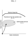
- the engine applied to the hybrid vehicle operates mainly at a maximum thermal efficiency operation point (or optimal operation point).
- a combustion temperature is lowered, and as a result, a specific heat ratio increases, which enhance efficiency of the hybrid vehicle.
- the engine may be operated in a theoretical air-fuel ratio mode except for the maximum thermal efficiency operation point.
- an engine speed synchronizes with a driving motor speed, and the clutch is coupled. Furthermore, a torque of the engine is gradually increased to a target torque, and the torque of the driving motor is gradually decreased, so an input-side torque of the transmission is controlled to reach a final torque required for driving.
- Such a process is referred to as torque blending.
- torque blending When the torque of the engine is increased in the torque blending process, the engine is operated in the theoretical air-fuel ratio mode, and as a result, a large amount of nitrogen oxide (NOx) is generated.
- NOx nitrogen oxide
- Various aspects of the present disclosure are directed to providing a hybrid vehicle which can enhance efficiency of an engine and reduce discharge of nitrogen oxide in a transition section in which the engine moves from a stop state to an optimal operation point area in which the engine operates in a lean burn combustion mode
- a hybrid vehicle including: an engine including a plurality of cylinders for generating power required for driving the hybrid vehicle by combustion of fuel; a first motor starting the engine, and selectively operating as a generator to generate electrical energy; a second motor generating power required for driving the hybrid vehicle; a clutch provided between the engine and the second motor; and a controller configured for synchronizing a velocity of the second motor and an engine velocity and for coupling the clutch, in a transition section in which the engine moves from a stop state to an optimal operation point area as an operation area of the engine, and gradually decreasing a torque of the second motor and gradually adjusting the number of combusted cylinders among the plurality of combustion chambers to gradually increase the engine torque.
- the number of combusted cylinders in the transition section may be increased stepwise whenever a set engine cycle elapses.
- the torque of the second motor in the transition section may be reduced as a ratio of the number of combusted cylinders increased whenever the set engine cycle elapses to a total number of cylinders.
- the cylinder of the engine may operate in a lean burn combustion mode in the transition section.
- An air-fuel ratio in the transition section may be set to be different from the air-fuel ratio in the optimal operation point area.
- the air-fuel ratio of the engine in the optimal operation point area may be set to be greater than the air-fuel ratio of the engine in the transition section.
- An engine torque output from a combusted cylinder may be gradually increased by adjusting an ignition time of the engine during the set engine cycle.
- the ignition time of the engine may be gradually advanced during the set engine cycle.
- Various aspects of the present disclosure are directed to providing a method for controlling a hybrid vehicle, including: in a transition section in which an engine moves from a stop state to an optimal operation point area as an operation area of the engine, increasing a velocity of the engine through power of a first motor and synchronizing the velocity of the engine with a velocity of a second motor; when the velocity of the engine is synchronized with the velocity of the second motor, coupling a clutch provided between the engine and the second motor; and when the clutch is coupled, gradually increasing a torque of the engine and gradually decreasing the torque of the second motor to output a final torque input into a transmission, in which in the outputting of the final torque, the torque of the engine may be gradually increased by adjusting the number of combusted cylinders among a plurality of combustion chambers of the engine.
- the number of combusted cylinders in the transition section may be increased stepwise whenever a set engine cycle elapses.
- the torque of the second motor in the transition section may be reduced at a ratio of the number of combusted cylinders to a total number of cylinders whenever the set engine cycle elapses.
- the cylinder of the engine may operate in a lean burn combustion mode in the transition section.
- An air-fuel ratio in the transition section may be set to be different from the air-fuel ratio in the optimal operation point area.
- the air-fuel ratio of the engine in the optimal operation point area may be set to be greater than the air-fuel ratio of the engine in the transition section.
- An engine torque output from a combusted cylinder may be gradually increased by adjusting an ignition time of the engine during the set engine cycle.
- the ignition time of the engine may be gradually advanced during the set engine cycle.
- discharge of nitrogen oxide may be minimized and unnecessary fuel consumption may be reduced in a transition section in which an engine moves from a stop state to an optimal operation point area.
- vibration or shock generated from the engine is minimized, and as a result, the shock applied to a power transmission system of a vehicle may be minimized.
- the hybrid vehicle according to the exemplary embodiment of the present disclosure described below will be described by taking a structure of a transmission mounted electric device (TMED) scheme as an ex.
- TMED transmission mounted electric device
- the scope of the present disclosure is not limited thereto, and the present disclosure may also be applied to other schemes of hybrid vehicles, of course.
- FIG. 1 is a conceptual view exemplarily illustrating a configuration of a hybrid vehicle according to various exemplary embodiments of the present disclosure.
- the hybrid vehicle may include an engine 10, a first motor 20, a second motor 30, a clutch 40, and a controller 60.
- the engine 10 includes a plurality of cylinders 11 for generating power required for driving the hybrid vehicle by combustion of fuel.
- the engine 10 may be a gasoline engine 10.
- the engine 10 according to the exemplary embodiment of the present disclosure may be a 4-cylinder engine, a 3-cylinder engine 10, or a 6-cylinder engine 10, and the scope of the present disclosure is not limited according to the number of cylinders of the engine 10.
- the first motor 20 may start the engine 10 and as necessary, selectively operates as a generator to generate electrical energy.
- the first motor 20 may be a kind of starter and generator.
- the second motor 30 generates the power required for driving the vehicle, and assists the power of the engine 10 as necessary. Furthermore, the second motor 30 selectively operates as the generator to generate the electrical energy.
- the clutch 40 is provided between the engine 10 and the second motor 30, and the hybrid vehicle is driven in an electric vehicle (EV) mode or a hybrid electric vehicle (HEV) mode according to the clutch 40 being coupled.
- EV electric vehicle
- HEV hybrid electric vehicle
- a mode in which the vehicle is driven only by the power of the second motor 30 is the electric vehicle (EV) mode and a mode in which the vehicle is driven by the power of the engine 10 and the power of the second motor 30 is a hybrid electric vehicle (HEV) mode.
- EV electric vehicle
- HEV hybrid electric vehicle
- the power outputted from the engine 10 and the second motor 30 is transmitted to a driving wheel provided in the vehicle though final drive (FD).
- the transmission 50 is provided between the clutch 40 and the driving wheel.
- a transmission gear is embedded in the transmission 50, and the power outputted from the engine 10 and the second motor 30 is changed according to a transmission gear stage.
- the controller 60 is configured to control components of the hybrid vehicle, which include the engine 10, the first motor 20, the second motor 30, and the clutch 40. Furthermore, the controller 60 is configured to control to synchronize a velocity of the second motor 30 and an engine velocity in a transition section in which the engine 10 moves from a stop state to an optimal operation point area as an operation area of the engine 10, and then decrease a torque of the second motor 30 and increase the torque of the engine 10, and output a final torque input into the transmission 50.
- the controller 60 may be provided as one or more processors which operate by a set program and the set program may be configured to perform each step of a method for controlling the hybrid vehicle according to the exemplary embodiment of the present disclosure.
- FIG. 2 is a graph illustrating an operating area of an engine applied to the hybrid vehicle according to the exemplary embodiment of the present disclosure.
- the operating area of the engine 10 applied to the hybrid vehicle according to the exemplary embodiment of the present disclosure may be divided into the optimal operation point area and a remaining area other than the optimal operation point area.
- the start of the engine 10 is stopped and the engine 10 is restarted or the engine 10 is idle-stopped and restarted according to the operation of an idle stop and go (ISG) system or when the vehicle is decelerated and accelerated, the start of the engine 10 is stopped and the engine 10 is restarted.
- ISG idle stop and go
- the engine 10 is stopped and restarted and the transition section frequently occurs in which the operation area of the engine 10 moves to the optimal operation point area.
- the transition section efficiency of the engine 10 is enhanced, and the discharge of the nitrogen oxide is reduced, and in a torque blending process, a continuous final toque input into the transmission 50 is outputted.
- FIG. 4 is a flowchart illustrating a method for controlling a hybrid vehicle according to various exemplary embodiments of the present disclosure.
- the controller 60 synchronizes the velocity of the second motor 30 with the engine velocity (S20).
- the controller 60 synchronizes the engine velocity with the velocity of the second motor 30 by increasing the engine velocity through the power of the first motor 20.
- the controller 60 couples the clutch 40 (S30).
- the controller 60 gradually decreases the torque of the second motor 30 and gradually increases the number of combusted cylinders 11 among the plurality of combustion chambers to gradually increase the engine torque (S40).
- a sum of an engine torque and the torque of the second motor 30 becomes the final torque input into the transmission 50.
- a section in which the engine torque is increased and the torque of the second motor 30 is decreased to maintain the final torque input into the transmission constantly is referred to as a torque blending section.
- the controller 60 increases the number of combusted cylinders 11 stepwise whenever a set engine cycle elapses.
- one cylinder 11 is combusted during the set engine cycle (e.g., an engine cycle of 3 times or 4 times), when the set engine cycle (e.g., the engine cycle of 3 times or 4 times) elapses, two cylinders 11 are combusted, when the set engine cycle (e.g., the engine cycle of 3 times or 4 times) elapses, three cylinders 11 are combusted, and when the set engine cycle (e.g., the engine cycle of 3 times or 4 times) elapses, four cylinders 11 are combusted.
- the set engine cycle e.g., the engine cycle of 3 times or 4 times
- one cylinder 11 is combusted during the set engine cycle (e.g., an engine cycle of 3 times or 4 times), and when the set engine cycle (e.g., the engine cycle of 3 times or 4 times) elapses, two cylinders 11 are combusted, when the set engine cycle (e.g., the engine cycle of 3 times or 4 times) elapses, three cylinders 11 are combusted, when the set engine cycle (e.g., the engine cycle of 3 times or 4 times) elapses, four cylinders 11 are combusted, when the set engine cycle (e.g., the engine cycle of 3 times or 4 times) elapses, five cylinders 11 are combusted, and when the engine cycle last set (e.g., the engine cycle of 3 times or 4 times) elapses, six cylinders 11 are combusted.
- the set engine cycle e.g., the engine cycle of 3 times or 4 times
- six cylinders 11 are combusted.
- two cylinders 11 may be combusted during the set engine cycle (e.g., an engine cycle of 3 times or 4 times), when the set engine cycle (e.g., the engine cycle of 3 times or 4 times) elapses, four cylinders 11 may be combusted, and when the set engine cycle (e.g., the engine cycle of 3 times or 4 times) elapses, six cylinders 11 may be combusted.
- the set engine cycle e.g., the engine cycle of 3 times or 4 times
- the number of cylinders 11 increased whenever the set engine cycle elapses may be appropriately determined according to a need of a designer.
- the torque output from the engine 10 increases stepwise in the torque blending section.
- the torque output from the engine 10 increases stepwise by 1/4 each.
- the motor torque output from the second motor 30 reduces the motor torque stepwise whenever the set engine cycle elapses so that the final torque input into the transmission 50 is maintained constantly.
- the motor torque output from the second motor 30 in the transition section is reduced as a ratio of the number of combusted cylinders increased whenever the set engine cycle elapses to a total number of cylinders.
- the motor torque output from the second motor 30 may decrease by 1/4 each of an initial motor torque.
- the motor torque output from the second motor 30 may decrease by 1/6 each of the initial motor torque.
- the final torque which is the sum of the engine torque output from the engine 10 and the motor torque output from the second motor 30 is constantly output.
- the cylinder 11 of the engine 10 is operated in the lean burn combustion mode.
- the air-fuel ratio of the engine 10 is set to be greater than the theoretical air-fuel ratio so that the engine 10 operates in the lean burn combustion mode.
- the controller 60 may determine an air amount for satisfying the air-fuel ratio for the engine 10 to operate in the lean burn combustion mode, and control a throttle valve, a boosting apparatus (e.g., a turbocharger, an electric supercharger, etc.), a continuously variable valve timing apparatus (CVVT), etc, to supply an air amount for the engine 10 to operate in the lean burn combustion to the cylinder 11.
- a throttle valve e.g., a turbocharger, an electric supercharger, etc.
- CVVT continuously variable valve timing apparatus
- a composition of exhaust gas discharged in the transition section in which all cylinders 11 of the engine 10 are not combusted and the composition of the exhaust gas discharged in the optimal operation point area in which all cylinders 11 of the engine 10 are combusted may be different, when an air amount for reaching the air-fuel ratio for performing lean burn combustion at the optimal operation point is supplied to the cylinder 11 in the transition section, there may be a difference between the air-fuel ratio of the cylinder 11 in the transition section and the air-fuel ratio at the optimal operation point.
- the temperature of the residual gas or the EGR gas amount in the optimal operation point area in which all cylinders 11 are combusted is different.
- the residual gas means exhaust gas which flows backward to the inside of the cylinder 11, in which all exhaust gas generated from the cylinder 11 is not discharged to an exhaust system.
- the temperature of the residual gas which flows backward in the optimal operation point area in which all cylinders 11 are combusted may be higher than the temperature of the residual gas which flows backward in the transition section, and the EGR gas amount in the optimal operation point area in which all cylinders 11 are combusted may be greater than the EGR gas amount in the transition section.
- the composition of the exhaust gas in the transition section is different from the composition of the exhaust gas in the optimal operation point area, when the air amount supplied to the cylinder 11 in the transition section is set to be equal to the air amount supplied to the cylinder 11 in the optimal operation point area, there may be a difference between the air-fuel ratio for implementing the lean burn combustion mode in the transition section and a set air-fuel ratio.
- the air-fuel ratio in the transition section and the air-fuel ratio in the optimal operation point area are set to be different, and as a result, the air amount supplied to the cylinder 11 in the transition section is set to made to be different from the air amount supplied to the cylinder 11 in the optimal operation point area. Therefore the air-fuel ratio in the transition section may be equal to the air-fuel ratio in the optimal operation point area.
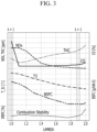
- the air-fuel ratio transit in the transition section may be set to be lower than the air-fuel ratio ⁇ steady in the optimal operation point area (see FIG. 6 ).
- controller 60 may adjust an ignition time of the engine 10 during the set engine cycle to continuously output the engine torque in the torque blending section as possible.
- the ignition time may be gradually advanced during the set engine cycle so that the engine torque may increase continuously and gently as possible.
- the engine torque output during the set engine cycle may gradually increase and the engine torque may be continuously output in the torque blending section.
- the hybrid vehicle and the control method thereof according to the exemplary embodiments of the present disclosure have been described by taking the 4-cylinder engine as an example.
- the scope of the present disclosure is not limited thereto, and the hybrid vehicle and the control method thereof may also be applied to the 3-cylinder engine 10 or the 6-cylinder engine 10, and the number of cylinders of the engine 10 may be appropriately changed and applied according to the designer.
- the hybrid vehicle and the control method thereof because the cylinder 11 combusted in the transition section in which the engine 10 is stopped and moves to the optimal operation point area of operating in the lean burn combustion mode operates in the lean burn combustion mode, the discharge of the nitrogen oxide may be minimized.
- the engine is not operated at the theoretical air-fuel ratio, but operates in the lean burn combustion mode in the transition section, unnecessary fuel consumption may be reduced.
- the output of the engine 10 in the transition section continuously increases, and as a result, vibration and shock generated from the engine 10 are minimized, minimizing the shock applied to a power transmission system of the vehicle.
- control device such as “controller”, “control apparatus”, “control unit”, “control device”, “control module”, or “server”, etc refers to a hardware device including a memory and a processor configured to execute one or more steps interpreted as an algorithm structure.
- the memory stores algorithm steps
- the processor executes the algorithm steps to perform one or more processes of a method in accordance with various exemplary embodiments of the present disclosure.
- the control device according to exemplary embodiments of the present disclosure may be implemented through a nonvolatile memory configured to store algorithms for controlling operation of various components of a vehicle or data about software commands for executing the algorithms, and a processor configured to perform operation to be described above using the data stored in the memory.
- the memory and the processor may be individual chips.
- the memory and the processor may be integrated in a single chip.
- the processor may be implemented as one or more processors.
- the processor may include various logic circuits and operation circuits, may process data according to a program provided from the memory, and may generate a control signal according to the processing result.
- the control device may be at least one microprocessor operated by a predetermined program which may include a series of commands for carrying out the method included in the aforementioned various exemplary embodiments of the present disclosure.
- the aforementioned invention can also be embodied as computer readable codes on a computer readable recording medium.
- the computer readable recording medium is any data storage device that can store data which may be thereafter read by a computer system and store and execute program instructions which may be thereafter read by a computer system.
- Examples of the computer readable recording medium include Hard Disk Drive (HDD), solid state disk (SSD), silicon disk drive (SDD), read-only memory (ROM), random-access memory (RAM), CD-ROMs, magnetic tapes, floppy discs, optical data storage devices, etc and implementation as carrier waves (e.g., transmission over the Internet).
- Examples of the program instruction include machine language code such as those generated by a compiler, as well as high-level language code which may be executed by a computer using an interpreter or the like.
- each operation described above may be performed by a control device, and the control device may be configured by a plurality of control devices, or an integrated single control device.
- control device may be implemented in a form of hardware or software, or may be implemented in a combination of hardware and software.
- unit for processing at least one function or operation, which may be implemented by hardware, software, or a combination thereof.
Applications Claiming Priority (1)
| Application Number | Priority Date | Filing Date | Title |
|---|---|---|---|
| KR1020210191405A KR20230102015A (ko) | 2021-12-29 | 2021-12-29 | 하이브리드 차량의 제어 장치 및 방법 |
Publications (1)
| Publication Number | Publication Date |
|---|---|
| EP4206015A1 true EP4206015A1 (de) | 2023-07-05 |
Family
ID=83151702
Family Applications (1)
| Application Number | Title | Priority Date | Filing Date |
|---|---|---|---|
| EP22192808.8A Pending EP4206015A1 (de) | 2021-12-29 | 2022-08-30 | Vorrichtung und verfahren zum steuern eines hybridfahrzeugs |
Country Status (3)
| Country | Link |
|---|---|
| US (1) | US20230202458A1 (de) |
| EP (1) | EP4206015A1 (de) |
| KR (1) | KR20230102015A (de) |
Citations (4)
| Publication number | Priority date | Publication date | Assignee | Title |
|---|---|---|---|---|
| US20030217877A1 (en) * | 2002-05-23 | 2003-11-27 | Honda Giken Kogyo Kabushiki Kaisha | Hybrid vehicle |
| US20110174256A1 (en) * | 2010-01-19 | 2011-07-21 | Toyota Jidosha Kabushiki Kaisha | Control apparatus and control method for internal combustion engine |
| DE102016204936A1 (de) * | 2016-03-24 | 2017-09-28 | Volkswagen Aktiengesellschaft | Verfahren zum Betrieb einer Antriebsvorrichtung für ein Hybrid-Kraftfahrzeug |
| DE102018122543A1 (de) * | 2018-09-14 | 2020-03-19 | Iav Gmbh Ingenieurgesellschaft Auto Und Verkehr | Verfahren zum Starten einer Brennkraftmaschine in einem Hybridfahrzeug mittels selektiver Zylinderabschaltung |
-
2021
- 2021-12-29 KR KR1020210191405A patent/KR20230102015A/ko unknown
-
2022
- 2022-08-30 EP EP22192808.8A patent/EP4206015A1/de active Pending
- 2022-08-31 US US17/900,034 patent/US20230202458A1/en active Pending
Patent Citations (4)
| Publication number | Priority date | Publication date | Assignee | Title |
|---|---|---|---|---|
| US20030217877A1 (en) * | 2002-05-23 | 2003-11-27 | Honda Giken Kogyo Kabushiki Kaisha | Hybrid vehicle |
| US20110174256A1 (en) * | 2010-01-19 | 2011-07-21 | Toyota Jidosha Kabushiki Kaisha | Control apparatus and control method for internal combustion engine |
| DE102016204936A1 (de) * | 2016-03-24 | 2017-09-28 | Volkswagen Aktiengesellschaft | Verfahren zum Betrieb einer Antriebsvorrichtung für ein Hybrid-Kraftfahrzeug |
| DE102018122543A1 (de) * | 2018-09-14 | 2020-03-19 | Iav Gmbh Ingenieurgesellschaft Auto Und Verkehr | Verfahren zum Starten einer Brennkraftmaschine in einem Hybridfahrzeug mittels selektiver Zylinderabschaltung |
Also Published As
| Publication number | Publication date |
|---|---|
| US20230202458A1 (en) | 2023-06-29 |
| KR20230102015A (ko) | 2023-07-07 |
Similar Documents
| Publication | Publication Date | Title |
|---|---|---|
| JP4519085B2 (ja) | 内燃機関の制御装置 | |
| JP4175361B2 (ja) | ハイブリッド車及びその制御方法 | |
| JP6926656B2 (ja) | ハイブリッド車両の制御装置 | |
| US10029675B2 (en) | Control device for hybrid vehicle | |
| JP2008121498A (ja) | 内燃機関装置およびこれを備える動力出力装置並びにこれを搭載する車両、内燃機関装置の制御方法 | |
| JP4876953B2 (ja) | 車両およびその制御方法 | |
| JP5772963B2 (ja) | ハイブリッド車両およびハイブリッド車両の制御方法 | |
| JP6464947B2 (ja) | ハイブリッド車両の制御装置 | |
| JP2009262753A (ja) | ハイブリッド自動車およびその制御方法 | |
| JP2008121497A (ja) | 内燃機関装置およびこれを備える動力出力装置並びにこれを搭載する車両、内燃機関装置の制御方法 | |
| JP2009052487A (ja) | 車両および車両に搭載された内燃機関の制御方法 | |
| JP2009137530A (ja) | 車両の動力出力装置 | |
| EP4206015A1 (de) | Vorrichtung und verfahren zum steuern eines hybridfahrzeugs | |
| JP2008115819A (ja) | 内燃機関装置およびこれを備える動力出力装置並びにこれを搭載する車両、内燃機関装置の点火制御方法 | |
| JP2006347430A (ja) | ハイブリッド車およびその制御方法 | |
| JP2007309113A (ja) | 動力出力装置、それを搭載した車両及び動力出力装置の制御方法 | |
| JP2006249983A (ja) | 動力出力装置およびこれを搭載する自動車並びにその制御方法 | |
| US11712959B2 (en) | System and method for controlling lock-up of engine clutch of hybrid vehicle | |
| JP2006316663A (ja) | 動力出力装置およびこれが備える内燃機関の始動方法 | |
| JP5569374B2 (ja) | 内燃機関装置および自動車 | |
| JP5330968B2 (ja) | 車両およびその制御方法 | |
| JP7192659B2 (ja) | ハイブリッド車両 | |
| JP6160463B2 (ja) | ハイブリッド車両の制御装置 | |
| JP2012153250A (ja) | 車両の制御装置 | |
| JP2008138606A (ja) | 内燃機関装置およびこれを備える動力出力装置並びにこれを搭載する車両、内燃機関装置の制御方法 |
Legal Events
| Date | Code | Title | Description |
|---|---|---|---|
| PUAI | Public reference made under article 153(3) epc to a published international application that has entered the european phase |
Free format text: ORIGINAL CODE: 0009012 |
|
| STAA | Information on the status of an ep patent application or granted ep patent |
Free format text: STATUS: THE APPLICATION HAS BEEN PUBLISHED |
|
| AK | Designated contracting states |
Kind code of ref document: A1 Designated state(s): AL AT BE BG CH CY CZ DE DK EE ES FI FR GB GR HR HU IE IS IT LI LT LU LV MC MK MT NL NO PL PT RO RS SE SI SK SM TR |
|
| P01 | Opt-out of the competence of the unified patent court (upc) registered |
Effective date: 20230707 |
|
| STAA | Information on the status of an ep patent application or granted ep patent |
Free format text: STATUS: REQUEST FOR EXAMINATION WAS MADE |
|
| 17P | Request for examination filed |
Effective date: 20231206 |
|
| RBV | Designated contracting states (corrected) |
Designated state(s): AL AT BE BG CH CY CZ DE DK EE ES FI FR GB GR HR HU IE IS IT LI LT LU LV MC MK MT NL NO PL PT RO RS SE SI SK SM TR |