EP4202173B1 - Elektromechanischer aktuator, verdunkelungsvorrichtung mit solch einem aktuator und verfahren zur montage solch eines aktuators - Google Patents
Elektromechanischer aktuator, verdunkelungsvorrichtung mit solch einem aktuator und verfahren zur montage solch eines aktuators Download PDFInfo
- Publication number
- EP4202173B1 EP4202173B1 EP22215374.4A EP22215374A EP4202173B1 EP 4202173 B1 EP4202173 B1 EP 4202173B1 EP 22215374 A EP22215374 A EP 22215374A EP 4202173 B1 EP4202173 B1 EP 4202173B1
- Authority
- EP
- European Patent Office
- Prior art keywords
- casing
- wall
- barrel
- electromechanical actuator
- end piece
- Prior art date
- Legal status (The legal status is an assumption and is not a legal conclusion. Google has not performed a legal analysis and makes no representation as to the accuracy of the status listed.)
- Active
Links
Images




Classifications
-
- E—FIXED CONSTRUCTIONS
- E06—DOORS, WINDOWS, SHUTTERS, OR ROLLER BLINDS IN GENERAL; LADDERS
- E06B—FIXED OR MOVABLE CLOSURES FOR OPENINGS IN BUILDINGS, VEHICLES, FENCES OR LIKE ENCLOSURES IN GENERAL, e.g. DOORS, WINDOWS, BLINDS, GATES
- E06B9/00—Screening or protective devices for wall or similar openings, with or without operating or securing mechanisms; Closures of similar construction
- E06B9/24—Screens or other constructions affording protection against light, especially against sunshine; Similar screens for privacy or appearance; Slat blinds
- E06B9/26—Lamellar or like blinds, e.g. venetian blinds
- E06B9/28—Lamellar or like blinds, e.g. venetian blinds with horizontal lamellae, e.g. non-liftable
- E06B9/30—Lamellar or like blinds, e.g. venetian blinds with horizontal lamellae, e.g. non-liftable liftable
- E06B9/32—Operating, guiding, or securing devices therefor
- E06B9/322—Details of operating devices, e.g. pulleys, brakes, spring drums, drives
-
- H—ELECTRICITY
- H02—GENERATION; CONVERSION OR DISTRIBUTION OF ELECTRIC POWER
- H02K—DYNAMO-ELECTRIC MACHINES
- H02K5/00—Casings; Enclosures; Supports
- H02K5/04—Casings or enclosures characterised by the shape, form or construction thereof
- H02K5/10—Casings or enclosures characterised by the shape, form or construction thereof with arrangements for protection from ingress, e.g. water or fingers
-
- H—ELECTRICITY
- H02—GENERATION; CONVERSION OR DISTRIBUTION OF ELECTRIC POWER
- H02K—DYNAMO-ELECTRIC MACHINES
- H02K5/00—Casings; Enclosures; Supports
- H02K5/04—Casings or enclosures characterised by the shape, form or construction thereof
- H02K5/22—Auxiliary parts of casings not covered by groups H02K5/06-H02K5/20, e.g. shaped to form connection boxes or terminal boxes
- H02K5/225—Terminal boxes or connection arrangements
-
- H—ELECTRICITY
- H02—GENERATION; CONVERSION OR DISTRIBUTION OF ELECTRIC POWER
- H02K—DYNAMO-ELECTRIC MACHINES
- H02K2207/00—Specific aspects not provided for in the other groups of this subclass relating to arrangements for handling mechanical energy
- H02K2207/03—Tubular motors, i.e. rotary motors mounted inside a tube, e.g. for blinds
Definitions
- the present invention relates to an electromechanical actuator of a concealment device, in other words an electromechanical actuator for a concealment device.
- the present invention also relates to a screening device comprising a rail and a screen.
- the screen is driven into movement by such an electromechanical actuator disposed inside the rail.
- the present invention further relates to a method of assembling such an electromechanical actuator.
- the present invention relates to the field of occultation devices comprising a motorized drive device setting a screen in motion, between at least a first position and at least a second position.
- a motorized drive device comprises an electromechanical actuator of a movable sun protection or closing element, such as a blind, in particular a slatted blind, a shutter, a door, a grille, a curtain or any other equivalent material, hereinafter called a screen.
- a movable sun protection or closing element such as a blind, in particular a slatted blind, a shutter, a door, a grille, a curtain or any other equivalent material, hereinafter called a screen.
- the pins can be contaminated by pollutants or wetted by flowing water.
- This type of electromechanical actuator has the disadvantage that the anchoring of the power supply cable to the housing is not permanent, to the point that tearing of the power supply cable cannot be ruled out.
- EP-A2-0 844 633 which describes an electromechanical actuator of a blackout device comprising an electric motor, a control unit configured to control the electric motor, a housing inside which The electric motor and the control unit are housed, as well as an electrical power cable that passes through a wall of the housing, being connected to the control unit.
- the anchoring of the power supply cable can be permanent, because tearing it off is difficult to achieve.
- a seal is threaded around the power supply cable and assembled inside the tapped hole of the housing stud, to ensure the seal between the ring placed around the power supply cable and the housing stud, by crushing the seal.
- Such an assembly requires not forgetting to place the seal in the tapped hole of the housing stud, during assembly, otherwise the seal is not ensured.
- EP 1 764 474 A1 which describes an electromechanical actuator of a concealment device.
- the electromechanical actuator comprises an electric motor, a control unit, a housing, a console, a plug and an electrical power cable.
- the control unit is configured to control the electric motor.
- the electric motor and the control unit are housed inside the housing.
- the electrical power cable passes through the console and is electrically connected to the control unit.
- the plug is configured to be attached to the console, so as to close an opening of a housing of the console, so that a passage of the electrical power cable is defined when the plug is assembled on the console.
- the present invention aims to solve the aforementioned drawbacks and to propose an electromechanical actuator for a concealment device, a concealment device comprising such an electromechanical actuator, as well as a method of assembling such an electromechanical actuator, making it possible to guarantee a durable and sealed anchoring of the electrical power supply cable on the casing and to prevent its twisting, thanks to a reliable, economical and easy to industrialize structure.
- the end of the power supply cable provides a triple function of anti-tearing of the power supply cable, anti-rotation and sealing, with respect to the wall of the housing.
- the end of the power supply cable makes it possible to make the mechanical connection between the power supply cable and the casing more reliable, while avoiding risks linked to a lack of sealing, in particular liquid leakage or dust passing into the casing, so as to effectively protect the electric motor and the control unit against power supply cuts and against pollution.
- the operation of the electromechanical actuator is made more reliable and it can meet a given protection rating, for example IP54, within the meaning of standard EN 60335.
- the invention relates to a method of assembling an electromechanical actuator for a blackout device, as mentioned above.
- This assembly process is quick to implement and provides a permanent and watertight anchoring of the electrical power cable, in particular without risk of liquid leakage or dust passing through, relative to the wall of the casing, with a limited number of steps, each step being simple to industrialize, in particular manually, by an operator.
- This installation 100 comprises an opening, window or door, equipped with a screen 2 belonging to a screening device 1, in accordance with an embodiment of the invention, in the example a screening device 1 of the Venetian blind type forming a slatted blind.
- the concealment device 1 may be, in particular, a pleated blind, a roller shutter, a rolling gate, a grille or a door.
- the occultation device 1 is preferably arranged outside the building.
- the occultation device 1 is arranged inside the building.
- the occulting device 1 comprises slats 3, in particular adjustable slats.
- the occulting device 1 further comprises a load bar 4.
- the screen 2 is formed of the slats 3 and the load bar 4.
- the load bar 4 makes it possible to exert tension on the screen 2.
- the load bar 4 is fixed at a lower end of the screen 2, in particular in an assembled configuration of the occultation device 1 in the installation 100.
- the screen 2 includes a final blade replacing the load bar 4, the latter being able to be weighted.
- the occulting device 1 comprises drive cords 5 configured to allow vertical movement of the blades 3 and the load bar 4.
- the drive cords 5 can also be called laces.
- the blades 3 respectively comprise openings, not shown, for the passage of each drive cord 5.
- the occultation device 1 further comprises orientation cords 6 configured to allow the orientation of the blades 3.
- the orientation cords 6 are also called ladders.
- each blade 3 of the screen 2 rests on a portion of orientation cord 6, in particular horizontal and which can be called a bar, connecting two strands of orientation cord 6, in particular vertical.
- orientation cords 6 make it possible to guarantee regular vertical spacing of the blades 3 of the screen 2.
- the orientation of the 3 blades allows, in particular, to adjust the brightness inside a room of the building.
- the concealment device 1 comprises two slides. Each of the slides is arranged along one side of the screen 2 of the concealment device 1. The slides are configured to cooperate with the blades 3 of the screen 2, so as to guide the blades 3, during the deployment and retraction of the screen 2.
- the blades 3 are guided by two cables. Each of the cables is arranged along one side of the screen 2 of the occultation device 1.
- the occulting device 1 comprises a motorized drive device 7.
- the motorized drive device 7 comprises at least one electromechanical actuator 8.
- the electromechanical actuator 8 is configured to drive, in other words, move the screen 2.
- the electromechanical actuator 8 makes it possible to lower or raise the slats 3 and the load bar 4, in other words to deploy or fold the screen 2, according to a vertical movement.
- the electromechanical actuator 8 also makes it possible to orient the slats 3.
- the occulting device 1 further comprises a rail 9, inside which is arranged the motorized drive device 7, in particular the electromechanical actuator 8, in particular in an assembled configuration of the occulting device 1.
- the rail 9 is arranged, in other words is configured to be arranged, above the screen 2, in particular in the assembled configuration of the occultation device 1.
- rail 9 is arranged above the building opening, or in the upper part of the building opening.
- the rail 9 comprises at least one bottom wall 9a and two side walls 9b.
- rail 9 has a “U” shaped section.
- the motorized drive device 7 further comprises a plurality of winders.
- the winders are configured to wind and unwind the drive cords 5, so as to drive the vertical movement of the blades 3 and the load bar 4.
- the motorized drive device 7 comprises two winders, not visible in the figure 1 .
- the number of reels is not limiting and may be different, in particular greater than two.
- the winders are arranged inside the rail 9.
- the drive cords 5 are connected, on the one hand, to the load bar 4 and, on the other hand, to the reels.
- each drive cord 5 is connected to the load bar 4 and the upper end of each drive cord 5 is connected to one of the winders.
- the motorized drive device 7 comprises tilting devices 13, generally called “tilters”. Each winder is respectively arranged inside a tilter 13. This is why the winders are not visible at the figure 1 .
- rockers 13 are arranged, in other words are configured to be arranged, inside the rail 9, in particular in the assembled configuration of the occultation device 1.
- the motorized drive device 7 comprises two rockers 13.
- the number of rockers is not limiting and may be different, in particular strictly greater than two. In the case where the number of rockers is greater than or equal to two, the electromechanical actuator may be arranged between two of the rockers.
- each rocker 13 is arranged on either side of the electromechanical actuator 8.
- each rocker 13 is arranged in the vicinity of one end of the rail 9, in the longitudinal direction thereof.
- the rockers 13 are configured to drive in rotation, over a limited range of rotation angle values, the orientation cords 6, so as to orient the blades 3.
- the motorized drive device 7, in particular the electromechanical actuator 8 is controlled by a control unit.
- the control unit is configured to control, i.e. command, the motorized drive device 7, in particular the electromechanical actuator 8.
- the control unit may be, for example, a local control unit 14 or a central control unit 15.
- the local control unit 14 can be connected, by wired or wireless connection, to the central control unit 15.
- the central control unit 15 can control the local control unit 14, as well as other similar local control units distributed throughout the building.
- the motorized drive device 7 is preferably configured to execute the movement commands, in particular for raising or lowering and, possibly, for orienting the screen 2 of the occultation device 1, which can be issued, in particular, by the local control unit 14 or the central control unit 15.
- the installation 100 and, more particularly, the concealment device 1 comprises either the local control unit 14, or the central control unit 15, or the local control unit 14 and the central control unit 15.
- Means for controlling the electromechanical actuator 8, allowing the movement of the screen 2 of the occultation device 1 as well as the orientation of the blades 3 of the screen 2, comprise at least one control unit 19, in particular an electronic control unit, illustrated in FIG. figure 3 .
- the control unit 19 is capable of operating an electric motor 18 of the electromechanical actuator 8 and, in particular, of enabling the supply of electrical energy to the electric motor 18.
- the electric motor 18 may be of the brushless type with electronic commutation, also called “BLDC” (acronym for the English term BrushLess Direct Current) or “synchronous with permanent magnets”, of the asynchronous type or of the direct current type.
- BLDC brushless type with electronic commutation
- synchronous with permanent magnets of the asynchronous type or of the direct current type.
- control unit 19 is integrated into the electromechanical actuator 8.
- control unit 19 controls, in particular, the electric motor 18, so as to open or close the screen 2, as well as so as to orient the blades 3 of the screen 2, as described previously.
- control unit 19 comprises a printed circuit board 42 which supports various electronic components necessary for controlling the electric motor 18, including those mentioned below.
- control unit 19 may comprise several printed circuit boards.
- control unit 19 comprises at least one communication module 49, in particular for receiving control orders, the control orders being sent by an order transmitter, such as the local control unit 14 or central 15, these orders being intended to control the motorized drive device 7.
- the communication module 49 of the control unit 19 is of the wired type, in other words it allows the reception and, possibly, the transmission of control orders transmitted by wired means.
- control unit 19, the local control unit 14 and/or the central control unit 15 can be in communication with a weather station, not shown, arranged inside the building or remote to the outside of the building, including, in particular, one or more sensors that can be configured to determine, for example, a temperature, a brightness or even a wind speed, in the case where the weather station is remote to the outside of the building.
- the control unit 19, the local control unit 14 and/or the central control unit 15 may also be in communication with a server 27, so as to control the electromechanical actuator 8 according to data made available remotely via a communication network, in particular an internet network which can be connected to the server 27.
- the control unit 19 can be controlled from the local control unit 14 or central control unit 15.
- the local control unit 14 or central control unit 15 is provided with a control keyboard.
- the control keyboard of the local control unit 14 or central control unit 15 comprises one or more selection elements 50 and, optionally, one or more display elements 51.
- the selection elements may be push buttons or sensitive keys
- the display elements may be light-emitting diodes, an LCD (acronym for the English term “Liquid Crystal Display”) or TFT (acronym for the English term “Thin Film Transistor”) display.
- the selection and display elements may also be produced by means of a touch screen.
- the local control unit 14 or central control unit 15 comprises at least one communication module 48.
- the communication module 48 of the local control unit 14 or central control unit 15 is configured to transmit, in other words emit, control orders, in particular by wired means.
- the communication module 48 of the local control unit 14 or central control unit 15 can also be configured to receive, in other words receive, control orders, in particular via the same means.
- the communication module 48 of the local control unit 14 or central control unit 15 is hereinafter referred to as the first communication module. Furthermore, the communication module 49 of the control unit 19 is hereinafter referred to as the second communication module.
- the first communication module 48 of the local control unit 14 or central control unit 15 is configured to communicate, in other words communicates, with the second communication module 49 of the control unit 19.
- the first communication module 48 of the local control unit 14 or central control unit 15 exchanges control orders with the second communication module 49 of the control unit 19, either in a one-way or two-way manner.
- the local control unit 14 is a control point, which may be fixed or mobile.
- a fixed control point may be a control box intended to be fixed on a facade of a wall of the building or on a face of the fixed frame of a window or a door.
- a mobile control point may be a remote control, a smartphone or a tablet.
- the local control unit 14 or central control unit 15 further comprises a controller 52.
- the control means of the electromechanical actuator 8 comprise hardware and/or software means.
- the hardware means may comprise at least one microcontroller 29 mounted on the printed circuit board 42.
- the motorized drive device 7, in particular the control unit 19, is preferably configured to execute movement control orders, in particular for deploying or retracting the screen 2 of the occultation device 1, as well as for orienting the slats 3. These control orders can be issued, in particular, by the local control unit 14 or by the central control unit 15.
- the motorized drive device 7 can be controlled by the user, for example by receiving a control command corresponding to pressing the or one of the selection elements 50 of the local 14 or central 15 control unit.
- the motorized drive device 7 can also be controlled automatically, for example by receiving a control command corresponding to at least one signal from at least one sensor, not shown, and/or a signal from a clock, not shown.
- the sensor and/or the clock can, alternatively, be integrated into the local control unit 14 or the central control unit 15.
- the sensor and/or clock may also be considered as corresponding to a control unit, in particular a local control unit 14.
- the electromechanical actuator 8 comprises, among other things, the electric motor 18 and the control unit 19.
- the electric motor 18 comprises a stator 182, a rotor 184 and a rotation shaft 186.
- the rotation shaft 186 is integral with the rotor 184.
- the rotation shaft 186 is configured to be driven in rotation, in other words is driven in rotation, about an axis of rotation X.
- the rotation shaft 186 protrudes at the two opposite ends of the electromechanical actuator 8 and constitutes an output shaft for this electromechanical actuator 8.
- the rotation shaft 186 is axially limited to the length of the electric motor 18 and connected to two output shafts of the electromechanical actuator 8 which respectively protrude at each of the ends thereof, or even to an output shaft which only protrudes at one end thereof.
- stator 182 and the rotor 184 are positioned coaxially around the axis of rotation X. Furthermore, the rotation shaft 186 is integrated or coupled to the rotor 184.
- the axis of rotation X is also the axis of rotation of the winders, in a mounted configuration of the motorized drive device 7.
- the electromechanical actuator 8 makes it possible to move the screen 2 of the occultation device 1, in particular in a vertical movement, as well as to orient the slats of the screen 2.
- the electromechanical actuator 8 further comprises an electrical power supply cable 10.
- the electromechanical actuator 8 is configured to be powered, in other words is powered, with electrical energy by a main electrical power source 54, via the electrical power supply cable 10.
- the main electrical power source 54 may be a mains electrical power supply network or a battery, which may be recharged, for example, by a photovoltaic panel or a charger, not shown.
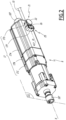
- the electromechanical actuator 8 further comprises a casing 17, in particular tubular.
- the electric motor 18 and the control unit 19 are housed, in other words mounted, inside the housing 17, in particular in an assembled configuration of the actuator. electromechanical 8.
- the casing 17 of the electromechanical actuator 8 comprises a plurality of sections, including at least three sections designated by the references 17A, 17B, 17C. It is of parallelepiped shape and, more particularly, has a generally rectangular section.
- the casing 17 of the electromechanical actuator 8 is cylindrical in shape with a circular section.
- the housing 17 is made at least partly of a metallic material.
- the material of the housing of the electromechanical actuator is not limiting and may be different. It may, in particular, be a plastic material.
- the electromechanical actuator 8 further comprises at least one reducer 12.
- the reducer 12 comprises at least one reduction stage.
- the reduction stage may be an epicyclic type gear train.
- the type and number of reduction stages of the reducer are not limiting.
- the reduction stages may be, for example, two or three in number.
- Each end of the rotation shaft 186 carries a sleeve 187 for coupling to a drive shaft 11 of one of the winders.
- Each reel is thus driven in rotation, at the level of one of the rockers 13, by one of the drive shafts 11 coupled with the rotation shaft 186 of the electromechanical actuator 8.
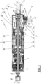
- the electromechanical actuator 8 further comprises a brake 46, as illustrated in figure 3 .
- the brake 46 may be a spring brake, a cam brake, a magnetic brake or an electromagnetic brake.
- the reducer 12 and the brake 46 are also housed in the casing 17 of the electromechanical actuator 8.
- the reducer 12 and the brake 46 are arranged outside the casing 17 of the electromechanical actuator 8.
- the electromechanical actuator 8 further comprises an end-of-travel detection device 21.
- the screen 2 comprises the plurality of blades 3, including a first blade 3h.
- the first blade 3h faces the bottom wall 9a of the rail 9, in particular in the assembled configuration of the occultation device 1.
- the first blade 3h of the screen 2 corresponds to the upper blade 3 of the screen 2.
- a high position in particular a safety position, corresponds to the first slat 3h of the screen 2 resting against an element of the end-of-travel detection device 21.
- the end-of-travel detection device 21 makes it possible, in particular, to determine whether the upper end-of-travel position of the screen 2 has been reached.
- the end-of-travel detection device 21 is generally called a “mushroom”.
- An upper end position in particular an operating end position, corresponds to a predetermined upper end position, in particular programmed by means of the control unit 19 and determined by means of a counting device 35.
- a lower end-of-travel position corresponds to a predetermined lower end-of-travel position, in particular programmed by means of the control unit 19 and determined by means of the counting device 35, or to the support of the load bar 4 against a threshold of the opening of the building, or even to the complete deployment of the screen 2.
- the counting device 35 may be of the magnetic type.
- Such a counting device 35 comprises at least one wheel, which can be assembled on the rotation shaft 186 of the electric motor 18, and Hall effect sensors, which are not shown in detail.
- the type of counting device 35 is not limiting and may be different, in particular of the optical type or of the time type and produced through the microcontroller 29 of the control unit 19.
- the end-of-travel detection device 21 comprises a member 22, movable inside a housing 17D formed by a part of the casing 17, in the example in one piece with the part 17A of the casing 17, and, optionally, an elastic return member 23 formed by a helical spring.
- the housing 17D of the end-of-travel detection device 21 may be formed by a part of the casing 17 attached to the part 17A of the casing 17 and fixed thereto, for example by means of fixing elements by screwing or by elastic snap-fastening.
- the housing 17D of the end-of-travel detection device 21 is cylindrical and has an internal section of generally circular shape.
- the housing 17D of the end-of-travel detection device 21 is parallelepipedal in shape.
- the elastic return member 23 may be other than a helical spring, for example a block of elastically deformable material.
- the member 22 is movable in translation along an axis A22 radial to the axis of rotation X.
- the member 22 is provided with a rectilinear rod 22A which is engaged in a hollow tube 17E, formed by a part of the casing 17 and which is centered on the axis A22.
- the translational movement of the member 22 along the axis A22 is guided by the cooperation of shapes of the parts 17E and 22A.
- the member 22 comprises a head 22B projecting from the housing 17D and intended to receive the first blade 3h in support, when the screen 2 reaches its upper end-of-travel position. To do this, the housing 17D and the member 22 are engaged from above in a slot, not shown, formed in the bottom wall 9a of the rail 9. When it is pushed back by the first blade 3h along the axis A22, the member 22 actuates a switch 43 carried by the printed circuit board 42. This allows the control unit 19 to detect that the screen 2 is in the upper end-of-travel position.
- the electromechanical actuator 8 further comprises a tilting control device 25.
- the tilt control device 25 is configured to switch, in other words toggles, the electronic control unit 19 between a first operating mode and a second operating mode.
- the electronic control unit 19 supplies electrical energy to the electric motor 18 according to the upward or downward movements to be performed by the screen 2, as well as the orientation movements to be performed by the slats 3 of the screen 2.
- the electronic control unit 19 implements the counting device 35 to determine and store one or more end-of-travel positions of the screen 2.
- the tilt control device 25 comprises a flap 26 pivotally mounted, around an axis A25, in a housing 17F, formed by a part of the casing 17, in the example in one piece with the part 17A of the casing 17.
- the casing 17 comprises at least one wall 17G.
- the wall 17G is an end wall of the assembled casing 17, in other words configured to be assembled, on the casing 17, in this case on the section 17A of the casing 17, in particular in the assembled configuration of the electromechanical actuator 8.
- the wall 17G is an integrated end wall of the casing 17, in other words forming an integral part of one of the sections 17A, 17B, 17C of the casing 17.
- the electrical power supply cable 10 passes through, in other words is configured to pass through, the wall 17G of the casing 17, in particular in the assembled configuration of the electromechanical actuator 8.
- the power supply cable 10 is electrically connected, i.e. is configured to be electrically connected, to the control unit 19, in particular in the assembled configuration of the electromechanical actuator 8.
- the wall 17G of the card 17 comprises an orifice 172 for the passage of the rotation shaft 186.
- This orifice 172 is aligned with the axis of rotation X, in the assembled configuration of the electromechanical actuator 8.
- X17 a longitudinal axis of the wall 17G which is defined as the central axis of the orifice 172 and which is coincident with the axis of rotation X, in the assembled configuration of the electromechanical actuator 8.
- the wall 17G of the casing 17 has an internal side S1, oriented towards the inside of the casing 17, in particular towards the electric motor 18 and the control unit 19, and an external side S2, oriented towards the outside of the casing 17, the internal side S1 being opposite the external side S2.
- the wall 17G of the casing 17 comprises a first sleeve 174.
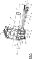
- the first sleeve 174 extends inside the casing 17, from the internal side S1 of the wall 17G, as illustrated in Figures 5 to 8 .
- the orifice 172 opens relative to the wall 17G of the casing 17 on the external side S2 and extends to the inside of the first sleeve 174.
- a bushing 187 is mounted on the rotation shaft 186, on the external side S2 of the wall 17G of the housing 17, as visible in the figure 4 .
- the wall 17G of the casing 17 further comprises a housing 176.
- the housing 176 opens onto the external side S2 of the wall 17G of the casing 17. Furthermore, the section of the housing 176, taken perpendicular to the longitudinal axis X17, is non-circular.
- the section, transverse to the longitudinal axis X17, of the housing 176 is rectangular with rounded corners.
- the section of the housing 176 may be different, for example oval or elliptical, while remaining non-circular.
- the wall 17G of the casing 17 further comprises a through opening 178. Furthermore, the through opening 178 is formed in the wall 17G of the casing 17, in particular in the extension of the non-circular section housing 176 formed in the wall 17G of the casing 17, in a direction parallel to the longitudinal axis X17.
- the wall 17G of the casing 17 further comprises a first shoulder 177, visible in the figure 7 . Furthermore, the first shoulder 177 forms a junction between the non-circular section housing 176 and the through opening 178 of the wall 17G of the casing 17.
- the through opening 178 is surrounded by a second sleeve 179 of the wall 17G of the casing 17.
- the second sleeve 179 extends projecting from the internal side S1 of the wall 17G of the casing 17, in particular beyond the first shoulder 177.
- the non-circular section housing 176 constitutes a mouth of the through opening 178, from the external side S2 of the wall 17G of the casing 17.
- the second sleeve 179 constitutes an internal relief of the wall 17G of the casing 17.
- S176 a surface of the housing with non-circular section 176, which delimits the latter, between the first shoulder 177 and the external side S2 of the wall 17G of the casing 17, and which can be called “internal surface”.
- S179 a surface of the second sleeve 179, which delimits the through opening 178, between the first shoulder 177 and the edge 179A, and which can be called “internal radial surface”.
- the surface S179 is cylindrical with a circular base.
- the through opening 178 is therefore a cylinder with a circular base.
- the second sleeve 179 is provided, on its surface S179, with two cutouts 179B which enlarge its internal diameter d179.
- the electrical power cable 10 includes electrical conductors 102, 104, 106, 108 and, optionally, an electrical insulation sheath 101. Further, the electrical insulation sheath 101 surrounds the electrical conductors 102, 104, 106, 108 over most of the length of the electrical power cable 10.
- 10A an end 10A of the electric power cable 10, from which the electric conductors 102, 104, 106, 108 are released from the electric insulation sheath 101.
- Each of the electrical conductors 102, 104, 106, 108 is equipped with an electrical terminal 103, 105, 107, 109 for connection to the control unit 19.
- each of the electrical conductors 102, 104, 106, 108 not protected by the electrical insulation sheath 101 is arranged inside the casing 17 and does not risk being damaged, or even cut, by an element external to the casing 17.
- the electromechanical actuator 8 further comprises an end piece 200. Furthermore, the end piece 200 is immobilized on the electrical power supply cable 10, in particular near its end 10A.
- the power supply cable 10 carries the tip 200.
- X10 a longitudinal axis of the electric power cable 10 and X200 a longitudinal axis of the end piece 200.
- the longitudinal axes X10 and X200 are merged in the vicinity of the end 10A of the electric power cable 10.
- the tip 200 comprises a frame 202, as visible in the figure 7 , in particular formed by a ring, which may be, for example, metallic.
- the armature 202 is tightened around the electrical power cable 10 and, more particularly, around the electrical insulation sheath 101, preferably in the vicinity of the end 10A of the electrical power cable 10.
- the frame 202 may be formed by a different part.
- the end piece 200 further comprises a part 204.
- the part 204 of the end piece 200 is immobilized on the electrical power cable 10.
- the frame 202 is visible by a partial tearing of the part 204.
- the part 204 of the end piece 200 is overmolded around the electrical power cable 10 and, more particularly, the frame 202 and the electrical insulation sheath 101, in this case close to the end 10A of the electrical power cable 10.
- the part 204 of the end piece 200 is overmolded both around the frame 202 and the electrical insulation sheath 101, to the point that the frame 202 is protected by the part 204 after overmolding.
- the end piece 200 is devoid of a frame 202.
- the part 204 is directly immobilized, in particular, overmolded on the electrical power cable 10 and, more particularly, on the electrical insulation sheath 101.
- the part 204 of the end piece 200 is not overmolded onto the electrical power supply cable 10, but is fixed thereto by another assembly technique, in particular by gluing or welding.
- the material constituting the part 204 of the end piece 200 is electrically insulating.
- it may be a plastic material.
- the end piece 200 further comprises a non-circular section portion 206, in particular in cross-section to the longitudinal axis X200. Furthermore, the non-circular section portion 206 of the end piece 200 is engaged in the non-circular section housing 176 formed in the wall 17G of the casing 17.
- the end piece 200 further comprises a barrel 208. Furthermore, the barrel 208 is engaged in the through opening 178 of the wall 17G of the casing 17.
- the barrel 208 which could also be called a “barrel” or “barrel”, is an elongated part of the end piece 200 which extends mainly along the longitudinal axis X200.
- a portion 209 of the barrel 208 protrudes from the through opening 178 on the internal side S1 of the wall 17G of the casing 17, in particular in the assembled configuration of the electromechanical actuator 8.
- the part 204 constitutes at least the non-circular section part 206 of the end piece 200 and the barrel 208 of the end piece 200.
- the non-circular section portion 206 of the end piece 200 is a heel.
- the non-circular section portion 206 of the tip 200 is configured to be received, i.e. is received, in the non-circular section housing 176, in particular in the assembled configuration of the electromechanical actuator 8. Furthermore, the barrel 208 of the tip 200 is configured to extend, i.e. extends, through the through opening 178, in particular in the assembled configuration of the electromechanical actuator 8.
- the barrel 208 is closer to the end 10A of the power supply cable 10 than the non-circular section portion 206 of the end piece 200.
- the cross-section at the axis X200 of the non-circular section part 206 of the end piece 200 is complementary to the section of the non-circular section housing 176, transverse to the longitudinal axis X17.
- the end piece 200 is immobilized in rotation, around the longitudinal axes X10, X200, with respect to the wall 17G of the casing 17, by cooperation of shapes between the part with non-circular section 206 and the housing with non-circular section 176.
- the cross-section at the longitudinal axis X200 of the non-circular section portion 206 of the end piece 200 is rectangular with rounded corners, like that of the non-circular section housing 176 formed in the wall 17G of the casing 17.
- the electrical conductors 102, 104, 106, 108 are inserted into the non-circular section housing 176 formed in the wall 17G of the casing 17 and through the through opening 178 formed in the wall 17G of the casing 17, from the external side S2 of the wall 17G, in the direction of arrow F1 to figures 7 And 8 , which makes them move from the configuration of figures 6 And 7 to the configuration of the figure 8 , then to the configuration of the figures 4 And 5 , where the barrel 208 protrudes from the through opening 178, beyond the edge 179A of the second sleeve 179.
- the end piece 200 further comprises a second shoulder 207. Furthermore, the second shoulder 207 is provided at an interface between the non-circular section portion 206 and the barrel 208 of the end piece 200.
- L179 denotes the length of the second sleeve 179 of the wall 17G of the casing 17, measured parallel to the longitudinal axis X17.
- the length L179 is equal to the length of the through opening 178 formed in the wall 17G of the casing 17, measured parallel to the longitudinal axis X17.
- the section of the barrel 208 of the end piece 200, in particular at the level of the part 209 of the barrel 208, taken perpendicular to the longitudinal axis X200, is circular.
- D208 is the diameter of the barrel 208 of the end piece 200, over the greater part of its length, in particular at the level of the part 209 of the barrel 208.
- the diameter D208 of the barrel 208 of the end piece 200 is chosen to be less than or equal to the internal diameter d179 of the second sleeve 179 of the wall 17G of the casing 17, to allow the barrel 208 to pass through the through opening 178.
- the barrel 208 comprises, on the part 209 of the barrel 208 extending beyond the through opening 178 on the internal side S1 of the wall 17G of the casing 17, one or more collar portions 210, which may be, for example, two in number, as illustrated in FIG. figure 6 .
- the collar portion(s) 210 are provided on the barrel 208 at one end of the end piece 200 opposite the non-circular section portion 206 of the end piece 200.
- the or each of the collar portions 210 extends over a portion of the circumference of the barrel 208 and locally increases its external diameter. Furthermore, the or each collar portion 210 is provided on the barrel 208 so as to pass through the or one of the cutouts 179B of the second sleeve 179, when the barrel 208 is introduced through the through opening 178 provided in the wall 17G of the casing 17, as explained below.
- the collar portion(s) 210 are arranged inside the casing 17, at a distance from the edge 179A of the second sleeve 179.
- the number and distribution of the collar portions is not limiting. They may be different, for example, one, three or more, with a distribution adapted to the geometry of the edge of the second sleeve.
- L208 the length of the barrel 208, measured parallel to the longitudinal axis X200, between the second shoulder 207 and the collar portion(s) 210.
- the length L208 is strictly greater than the length L179, to the point that the part 209 of the barrel 208 protrudes beyond the edge 179A of the second sleeve 179, in other words the through opening 178, on the internal side S1 of the wall 17G of the casing 17, when the first and second shoulders 177, 207 are in abutment against each other.
- the part 209 of the barrel 208 is grayed out at figure 8 .
- L209 the length of the part 209 of the barrel 208, measured parallel to the longitudinal axis X200.
- L209 L208 ⁇ L179
- the electromechanical actuator 8 further comprises a retaining member 220. Furthermore, the retaining member 220 is mounted, in other words is configured to be mounted, on the part 209 of the barrel 208, in particular in the assembled configuration of the electromechanical actuator 8.
- the retaining member 220 is installed around the part 209 of the barrel 208, between the edge 179A of the second sleeve 179 of the wall 17G of the casing 17 and the collar portion(s) 210 of the barrel 208.
- the barrel 208 forms a receiving zone for the retaining member 220, in other words configured to receive the retaining member 220, in this case the external peripheral surface of the part 209 of the barrel 208, outside the collar portion(s) 210, and this receiving zone has a diameter D208.
- the retaining member 220 axially retains the end piece 200 relative to the wall 17G of the casing 17, in its position where the second shoulder 207 is pressed against the first shoulder 177, with the non-circular section part 206 of the end piece 200 in place in the non-circular section housing 176.
- the retaining member 220 can be installed between the collar portion(s) 210 of the barrel 208 and another internal relief of the wall 17G of the casing 17 different from the edge 179A of the second sleeve 179.
- the retaining member 220 is a ring, which may be, for example, made of metal, such as spring steel.
- the ring forming the retaining member 220 is elastically deformable, between a first configuration, called “rest” or “initial”, where its internal diameter d220 is less than or equal to the diameter D208 of the barrel 208, on the zone formed by the barrel 208 for receiving the retaining member 220, and a second configuration, called “assembly”, where its internal diameter d220 is strictly greater than a maximum diameter D210 of the barrel 208.
- the retaining member 220 comprises two tabs 222, 224. Furthermore, the tabs 222, 224 make it possible to exert a pinching force, represented by the arrows F2 in the figure. figure 7 , so as to elastically deform the retaining member 220, to temporarily increase its internal diameter d220.
- the pinching force exerted on the tabs 222, 224 makes it possible to engage the retaining member 220 on the part 209 of the barrel 208, protruding from the second sleeve 179 of the wall 17G of the casing 17 towards the inside of the casing 17.
- the retaining member 220 passes from its first configuration, where its internal diameter d220 is less than or equal to the diameter D208 of the barrel 208, to its second configuration, where its internal diameter d220 is greater than or equal to the external diameter D210 of the collar portion(s) 210, which constitutes a maximum diameter of the barrel 208.
- the retaining member 220 returns to its first configuration, by elastic return.
- the geometry of the retaining member 220 is determined such that its unstressed internal diameter d220, i.e. in the absence of pinching force on the tabs 222, 224, is less than or equal to the diameter D208 of the barrel 208. In this way, immobilization of the end piece 200 relative to the wall 17G of the casing 17, in the direction of the longitudinal axis X200, is guaranteed by elastic clamping of the retaining member 220 on the barrel 208 and, more particularly, on the part 209 of the barrel 208.
- t220 the width of the retaining member 220, measured parallel to a central axis A220 of the retaining member 220.
- the central axis A220 of the retaining member 220 coincides with the longitudinal axis X200 of the end piece 200, in an assembled configuration of the retaining member 220 on the barrel 208.
- the width e220 of the retaining member 220 is equal to or less, for example, to within 5%, compared to the length L209 of the part 209 of the barrel 208.
- the output member 220 covers most of this part 209 of the barrel 208, so as to avoid a tearing movement of the end piece 200 relative to the wall 17G of the casing 17 or to limit an amplitude of such a movement.
- width e220 of the retaining member 220 is equal to the length L209 of the part 209 of the barrel 208, then no axial movement of the end piece 200 in the non-circular section housing 176 and in the through opening 178 of the wall 17G of the casing 17 is possible.
- width e220 of the retaining member 220 is strictly less than the length L209 of the part 209 of the barrel 208, then axial movement is possible, over a stroke equal to the difference between these dimensions.
- the barrel 208 carries at least one first sealing lip 212. Furthermore, the or each first sealing lip 212 is in contact with the surface S179, delimiting the through opening 178 formed in the wall 17G of the casing 17.
- the barrel 208 comprises a plurality of first sealing lips 212, in particular three in number.
- the first sealing lips 212 are axially offset along the longitudinal axis X200 of the end piece 200.
- the first sealing lips 212 surround the barrel 208 over its entire circumference.
- the first sealing lips 212 are located near the non-circular section portion 206 of the end piece 200, that is to say on the side of the barrel 208 opposite the side of the barrel 208 having the collar portion(s) 210.
- the first sealing lips 212 are provided on a portion of the barrel 208 distinct from the portion 209 of the barrel 208 projecting from the through opening 178 on the internal side S1 of the wall 17G of the casing 17.
- the number of first sealing lips is not limiting. It may be different from three, for example equal to one or two, or even greater than or equal to four.
- the non-circular section portion 206 of the end piece 200 and the portion 209 of the barrel 208 are arranged, along the longitudinal axis X200, on either side of the first sealing lip(s) 212. In other words, the non-circular section portion 206 of the end piece 200 is opposite, relative to the first sealing lips 212, the portion 209 of the barrel 208.
- the diameter D208 is the diameter of the barrel 208 between the collar portions 210 and the first sealing lips 212.
- the or each first sealing lip 212 is configured to be in contact, in other words is in contact, with the surface S179 of the second sleeve 179 of the wall 17G of the casing 17, in particular in an assembled configuration of the end piece 200 with the wall 17G of the casing 17, so as to guarantee a seal between the end piece 200 of the electrical power supply cable 10 and the wall 17G of the casing 17, inside the through opening 178 formed in the wall 17G of the casing 17.
- the or each first sealing lip 212 prevents liquid from flowing or dust from infiltrating from the outside of the housing 17 to the inside of the housing 17.
- the or each first sealing lip 212 is in one piece with the part 204 of the end piece 200.
- each first sealing lip 212 may be formed by a segment attached around the barrel 208.
- the non-circular section portion 206 of the end piece 200 carries at least one second sealing lip 213. Furthermore, in the assembled configuration of the end piece 200 with the wall 17G of the casing 17, the or each second sealing lip 213 is in contact with the surface S176, delimiting the non-circular section housing 176 formed in the wall 17G of the casing 17.
- the non-circular section portion 206 of the end piece 200 comprises two second sealing lips 213. Furthermore, the second sealing lips 213 surround the non-circular section portion 206 of the end piece 200 over its entire circumference.
- the number of second sealing lips is not limiting. It may be different from two, for example equal to one or greater than or equal to three.
- the or each second sealing lip 213 is configured to be in contact, in other words is in contact, with the surface S176 of the non-circular section housing 176 formed in the wall 17G of the casing 17, in particular in the assembled configuration of the end piece 200 with the wall 17G of the casing 17, so as to ensure a seal between the end piece 200 of the electrical power supply cable 10 and the wall 17G of the casing 17, inside the non-circular section housing 176 formed in the wall 17G of the casing 17.
- the or each second sealing lip 213 prevents liquid from flowing or dust from infiltrating from the outside of the housing 17 to the inside of the housing 17.
- the or each second sealing lip 213 is in one piece with the part 204 of the end piece 200.
- each second sealing lip 213 may be formed by a segment added around the non-circular section portion 206.
- FIG. Figures 2 to 8 An embodiment of a method of assembling the electromechanical actuator 8, illustrated in FIG. Figures 2 to 8 , in accordance with the invention, and, more particularly, a part relating to the assembly of the electrical power supply cable 10 with the wall 17G of the casing 17.
- the assembly method comprises a first step of inserting the electrical conductors 102, 104, 106, 108 of the electrical power supply cable 10 into the through opening 178 formed in the wall 17G of the casing 17, in particular through the non-circular section housing 176 formed in the wall 17G of the casing 17, starting from the external side S2 of the wall 17G of the casing 17 towards the inside of the casing 17, in the direction of the arrow F1 at figures 7 And 8 .
- This insertion step is carried out until the non-circular section portion 206 of the end piece 200 of the electrical power supply cable 10 is received in the non-circular section housing 176 formed in the wall 17G of the casing 17 and the or each first sealing lip 212 is in contact with the surface S179, delimiting the through opening 178 formed in the wall 17G of the casing 17.
- the assembly method comprises a second step of mounting the retaining member 220 on the part 209 of the barrel 208 protruding from the through opening 178 on the internal side S1 of the wall 17G of the casing 17, by axially locking the end piece 200 relative to the wall 17G of the casing 17, in the position reached at the end of the first insertion step.
- the retaining member 220 is put in place around the part 209 of the barrel 208. Furthermore, the retaining member 220 axially locks, along the longitudinal axes X10, X17, X200, the end piece 200 in the position reached at the end of the first insertion step, where the end piece 200 extends through the wall 17G of the casing 17, by means of the non-circular section housing 176 and the through opening 178.
- the retaining member 220 is held in abutment against the edge 179A of the second sleeve 179 of the wall 17G of the casing 17 and against the collar portion(s) 210 of the barrel 208, in a position where the non-circular section part 206 of the end piece 200 is received in the non-circular section housing 176 formed in the wall 17G of the casing 17, while being blocked in rotation about the longitudinal axes X10, X200.
- this assembly makes it possible to avoid risks of twisting of the electrical power supply cable 10, while the or each first sealing lip 212 is in contact with the surface S179 of the through opening 178, so as to improve the sealing of the assembly thus produced.
- the assembly of the power supply cable on the wall of the housing is simple and quick, while the end piece of the power supply cable ensures a triple function of anti-tearing of the power supply cable, anti-rotation and sealing, with respect to the wall of the housing.
- the end piece of the power supply cable makes it possible to make the mechanical connection between the power supply cable and the housing more reliable, while avoiding risks linked to a lack of sealing, in particular liquid leakage or dust passage, towards the inside of the housing.
- the operation of the electromechanical actuator is made more reliable and it can meet a given protection rating, in particular a protection rating according to standard EN 60335.
- the motorized drive device 7 comprises, in addition to a plurality of first winders of the drive cords 5, a plurality of second winders of the orientation cords 6.
- the drive cords 5 are connected, on the one hand, to the load bar 4 and, on the other hand, to the first winders.
- the orientation cords 6 are connected, on the one hand, to the load bar 4 and to the blades 3 and, on the other hand, to the second winders.
- the lower end of each drive cord 5 is connected to the load bar 4 and the upper end of each drive cord 5 is connected to one of the first winders, in particular in the assembled configuration of the occultation device 1 in the installation 100.
- each orientation cord 6 is connected to the load bar 4 and the upper end of each orientation cord 6 is connected to one of the second winders, in particular in the assembled configuration of the occultation device 1 in the installation 100.
- the first and second winders are arranged inside the rail 9.
- the motorized drive device 7 comprises two chains for driving and orienting the blades 3 of the screen 2, replacing the drive cords 5 and the orientation cords 6.
- each chain is arranged inside one of the slides, arranged along one side of the screen 2 of the occultation device 1.
- the second communication module 49 of the control unit 19 is configured to receive, in other words receives, and, optionally, to transmit, in other words transmits, control orders transmitted by wireless means, in particular, radioelectric control orders.
- the first communication module 48 of the local control unit 14 or central control unit 15 is configured to transmit, in other words transmits, and, optionally, to receive, in other words receives, control orders, in particular by wireless means, for example radioelectric.
Landscapes
- Engineering & Computer Science (AREA)
- Power Engineering (AREA)
- Structural Engineering (AREA)
- Architecture (AREA)
- Civil Engineering (AREA)
- Power-Operated Mechanisms For Wings (AREA)
- Motor Or Generator Frames (AREA)
Claims (10)
- Elektromechanischer Aktuator (8) für eine Verdunkelungsvorrichtung (1),der elektromechanische Aktuator (8) mindestens umfassend:- einen Elektromotor (18),- eine Steuereinheit (19), wobei die Steuereinheit (19) konfiguriert ist, um den Elektromotor (18) zu steuern,- ein Gehäuse (17), wobei der Elektromotor (18) und die Steuereinheit (19) im Inneren des Gehäuses (17) untergebracht sind,- ein Stromversorgungskabel (10), wobei das Stromversorgungskabel (10) eine Wand (17G) des Gehäuses (17) durchquert und elektrisch mit der Steuereinheit (19) verbunden ist, wobei die Wand (17G) des Gehäuses (17) eine Innenseite (S1), die zum Inneren des Gehäuses (17) gerichtet ist, und eine Außenseite (S2), die zum Äußeren des Gehäuses (17) gerichtet ist, aufweist, wobei die Innenseite (S1) gegenüber der Außenseite (S2) ist, und- ein Halteelement (220),dadurch gekennzeichnet,dass der elektromechanische Aktuator (8) ferner Folgendes umfasst:- ein Endstück (200), wobei das Endstück (200) an dem Stromversorgungskabel (10) fixiert ist,dass das Gehäuse (17) mindestens Folgendes umfasst:- ein Gehäuse (176) mit nicht kreisförmigem Querschnitt, wobei das Gehäuse (176) mit nicht kreisförmigem Querschnitt in der Wand (17G) des Gehäuses (17) ausgebildet ist, und- eine Durchgangsöffnung (178), wobei die Durchgangsöffnung (178) in der Wand (17G) des Gehäuses (17) ausgebildet ist,dass das Endstück (200) mindestens Folgendes umfasst:- einen Teil (206) mit nicht kreisförmigem Querschnitt, wobei der Teil (206) mit nicht kreisförmigem Querschnitt der Spitze (200) in die Aufnahme (176) mit nicht kreisförmigem Querschnitt eingreift, die in der Wand (17G) des Gehäuses (17) ausgebildet ist, und- einen Schaft (208), wobei der Schaft (208) in die Durchgangsöffnung (178) der Wand (17G) des Gehäuses (17) eingreift, wobei ein Teil (209) des Schafts (208) aus der Durchgangsöffnung (178) auf der Innenseite (S1) der Wand (17G) des Gehäuses (17) hervorsteht, wobei das Halteelement (220) an dem Abschnitt (209) des Schafts (208) montiert ist,und dadurch, dass der Schaft (208) mindestens eine Dichtlippe (212) trägt, wobei die oder jede Dichtlippe (212) in Kontakt mit einer Oberfläche (S179) ist, die die Durchgangsöffnung (178) begrenzt, die in der Wand (17G) des Gehäuses (17) ausgebildet ist.
- Elektromechanischer Aktuator (8) für eine Verdunkelungsvorrichtung (1) nach Anspruch 1, dadurch gekennzeichnet, dass die Endkappe (200) ferner eine Armatur (202) umfasst, wobei die Armatur (202) um das Stromversorgungskabel (10) geklemmt ist.
- Elektromechanischer Aktuator (8) für eine Verdunkelungsvorrichtung (1) nach Anspruch 1 oder nach Anspruch 2, dadurch gekennzeichnet, dass das Endstück (200) ferner ein Teil (204) umfasst, wobei das Teil (204) zumindest den Teil mit nicht kreisförmigem Querschnitt (206) des Endstücks (200) und den Schaft (208) des Endstücks (200) bildet, wobei das Teil (204) an dem Stromversorgungskabel (10) fixiert ist.
- Elektromechanischer Aktuator (8) für eine Verdunkelungsvorrichtung (1) nach einem der Ansprüche 1 bis 3, dadurch gekennzeichnet, dass die in der Wand (17G) des Gehäuses (17) gebildete Aufnahme (176) mit nicht kreisförmigem Querschnitt eine Mündung der in der Wand (17G) des Gehäuses (17) gebildeten Durchgangsöffnung (178) bildet, die von der Außenseite (S2) der Wand (17G) des Gehäuses (17) aus gebildet ist.
- Elektromechanischer Aktuator (8) für eine Abdeckvorrichtung (1) nach Anspruch 4, dadurch gekennzeichnet,
dass der Teil mit nicht kreisförmigem Querschnitt (206) des Endstücks (200) ein Absatz ist, und dass die Dichtlippe(n) (212) an einem Abschnitt des Schafts (208) bereitgestellt ist (sind), der von dem Teil (209) des Schafts (208) getrennt ist, der aus der Durchgangsöffnung (178) auf der Innenseite (S1) der Wand (17G) des Gehäuses (17) hervorsteht. - Elektromechanischer Aktuator (8) für eine Verdunkelungsvorrichtung (1) nach Anspruch 5, dadurch gekennzeichnet, dass die oder jede Dichtlippe (212) an dem Schaft (208) in der Nähe des Teils mit nicht kreisförmigem Querschnitt (206) des Endstücks (200) ausgebildet ist.
- Elektromechanischer Aktuator (8) für eine Abdeckvorrichtung (1) nach einem der Ansprüche 1 bis 6, dadurch gekennzeichnet,dass der Schaft (208) an dem Teil (209) des Schafts (208), der aus der Durchgangsöffnung (178) an der Innenseite (S1) der Wand (17G) des Gehäuses (17) hervorsteht, mindestens einen Flanschabschnitt (210) umfasst,und dass das Halteelement (220) zwischen dem oder jedem Flanschabschnitt (210) des Schafts (208) und einem Relief (179A) der Wand (17G) des Gehäuses (17) eingefügt ist, wenn die Spitze (200) mit der Wand (17G) des Gehäuses (17) zusammengesetzt ist.
- Elektromechanischer Aktuator (8) für eine Verdunkelungsvorrichtung (1) nach einem der Ansprüche 1 bis 7, dadurch gekennzeichnet, dass das Halteelement (220) ein elastisch verformbarer Ring zwischen einer ersten Konfiguration, in der sein Innendurchmesser (d220) kleiner als oder gleich wie ein Durchmesser (D208) des Schafts (208) ist, über einen Bereich, der durch den Schaft (208) zum Aufnehmen des Halteelements (220) gebildet ist, und einer zweiten Konfiguration, in der sein Innendurchmesser (d220) strikt größer ist als ein maximaler Durchmesser (D210) des Schafts (208), ist.
- Verdunkelungsvorrichtung (1), die Verdunkelungsvorrichtung (1) mindestens umfassend:- eine Schiene (9),- einen Schirm (2), und- einen elektromechanischen Aktuator (8) nach einem der Ansprüche 1 bis 8, wobei der elektromechanische Aktuator (8) in der Schiene (9) angeordnet ist, wobei der Schirm (2) durch den elektromechanischen Aktuator (8) in Bewegung versetzt wird.
- Verfahren zur Montage eines elektromechanischen Aktuators (8) für eine Verdunkelungsvorrichtung (1) nach einem der Ansprüche 1 bis 8, dadurch gekennzeichnet, dass das Verfahren mindestens die folgenden Schritte umfasst:- Einführen von elektrischen Leitern (102, 104, 106, 108) des Stromversorgungskabels (10) in die Durchgangsöffnung (178) in der Wand (17G) des Gehäuses (17), bis der nicht kreisförmige Teil (206) des Endstücks (200) des Stromkabels (10) in der nicht kreisförmigen Aufnahme (176) in der Wand (17G) des Gehäuses (17) aufgenommen ist und die oder jede Dichtlippe (212) die Oberfläche (S179) berührt, die die Durchgangsöffnung (178) in der Wand (17G) des Gehäuses (17) begrenzt, und- Montieren des Halteelements (220) an dem Teil (209) des Schafts (208), der aus der Durchgangsöffnung (178) auf der Innenseite (S1) der Wand (17G) des Gehäuses (17) hervorsteht, durch axiales Verriegeln der Spitze (200) in Bezug auf die Wand (17G) des Gehäuses (17) in der Position, die am Ende des Einführschritts erreicht wird.
Applications Claiming Priority (1)
| Application Number | Priority Date | Filing Date | Title |
|---|---|---|---|
| FR2114290A FR3130871B1 (fr) | 2021-12-22 | 2021-12-22 | Actionneur électromécanique, dispositif d’occultation comprenant un tel actionneur et procédé d’assemblage d’un tel actionneur |
Publications (2)
| Publication Number | Publication Date |
|---|---|
| EP4202173A1 EP4202173A1 (de) | 2023-06-28 |
| EP4202173B1 true EP4202173B1 (de) | 2025-01-01 |
Family
ID=80786524
Family Applications (1)
| Application Number | Title | Priority Date | Filing Date |
|---|---|---|---|
| EP22215374.4A Active EP4202173B1 (de) | 2021-12-22 | 2022-12-21 | Elektromechanischer aktuator, verdunkelungsvorrichtung mit solch einem aktuator und verfahren zur montage solch eines aktuators |
Country Status (3)
| Country | Link |
|---|---|
| EP (1) | EP4202173B1 (de) |
| FR (1) | FR3130871B1 (de) |
| PL (1) | PL4202173T3 (de) |
Family Cites Families (4)
| Publication number | Priority date | Publication date | Assignee | Title |
|---|---|---|---|---|
| DE19648825A1 (de) | 1996-11-26 | 1998-05-28 | Alsthom Cge Alcatel | Endlagenschaltvorrichtung einer elektromotorisch angetriebenen Jalousie |
| FR2891001B1 (fr) * | 2005-09-19 | 2007-11-30 | Somfy Sas | Actionneur electrique |
| FR2891413B1 (fr) * | 2005-09-28 | 2008-02-08 | Fp2X Groupement D Interet Econ | Dispositif de moteur electrique tubulaire |
| FR2923329B1 (fr) * | 2007-11-05 | 2015-04-24 | Fp2X | Dispositif d'obturation et de passage de cable electrique pour moteur tubulaire |
-
2021
- 2021-12-22 FR FR2114290A patent/FR3130871B1/fr active Active
-
2022
- 2022-12-21 PL PL22215374.4T patent/PL4202173T3/pl unknown
- 2022-12-21 EP EP22215374.4A patent/EP4202173B1/de active Active
Also Published As
| Publication number | Publication date |
|---|---|
| FR3130871A1 (fr) | 2023-06-23 |
| EP4202173A1 (de) | 2023-06-28 |
| FR3130871B1 (fr) | 2023-12-22 |
| PL4202173T3 (pl) | 2025-03-17 |
Similar Documents
| Publication | Publication Date | Title |
|---|---|---|
| EP3880930B1 (de) | Elektromechanischer aktuator und beschattungsvorrichtung mit einem solchen aktuator | |
| EP4172452B1 (de) | Beschattungsvorrichtung mit einer motorischen antriebseinrichtung | |
| EP3695086B1 (de) | Rohrmotor, heimautomatisierung mit diesem motor und sein herstellungsverfahren | |
| WO2019072837A1 (fr) | Actionneur électromécanique tubulaire et installation domotique comprenant un tel actionneur | |
| EP3695087B1 (de) | Rohrförmiger elektromechanischer aktuator, heimautomatisierungsausrüstung mit solch einem aktuator und verfahren zur verbindung solch eines aktuators | |
| EP3695085B1 (de) | Rohrmotor und heimautomatisierung mit diesem motor | |
| EP3969715B1 (de) | Elektromechanischer aktuator und verschluss-, abdeck- oder sonnenschutzinstallation mit solch einem elektromechanischen aktuator | |
| EP4008876B1 (de) | Elektromechanisches stellglied und verschluss-, verdunkelungs- oder sonnenschutzanlage, die ein solches stellglied umfasst | |
| EP3372774B1 (de) | Konfigurations- und funktionssteuerungsverfahren einer motorisierten antriebsvorrichtung einer haustechnikanlage, entsprechende motorisierte antriebsvorrichtung und entsprechende anlage | |
| EP4174276B1 (de) | Elektromechanischer aktuator, verdunkelungsvorrichtung mit solch einem aktuator und verfahren zur steuerung solch eines aktuators | |
| EP4202173A1 (de) | Elektromechanischer aktuator, verdunkelungsvorrichtung mit solch einem aktuator und verfahren zur montage solch eines aktuators | |
| EP4355975B1 (de) | Verdunkelungsvorrichtung | |
| EP3190253B1 (de) | Dreh-kippfenster für ein gebäude, und hausanlage, die ein solches dreh-kippfenster umfasst | |
| EP4162139B1 (de) | Elektromechanischer aktuator für eine beschattungsvorrichtung und beschattungsvorrichtung mit einem solchen elektromechanischen aktuator | |
| EP4290745B1 (de) | Elektromechanischer aktuator und verdunkelungsvorrichtung mit solch einem aktuator | |
| EP3954857B1 (de) | Abdeckvorrichtung, die eine motorisierte antriebsvorrichtung umfasst | |
| EP4047170B1 (de) | Elektromechanisches stellglied, motorbetriebene antriebsvorrichtung mit einem solchen elektromechanischen stellglied und verdunkelungsvorrichtung mit einer solchen motorbetriebenen antriebsvorrichtung | |
| EP3835538B1 (de) | Elektromechanisches stellglied, das ein aufhängungsorgan umfasst, und schliess- oder sonnenschutzanlage, die ein solches elektromechanisches stellglied umfasst | |
| FR3157978A1 (fr) | Actionneur électromécanique, dispositif d'occultation comprenant un tel actionneur électromécanique et procédé d’assemblage d’un tel actionneur électromécanique | |
| WO2022207133A1 (fr) | Actionneur électromécanique et installation de fermeture, d'occultation ou de protection solaire comprenant un tel actionneur électromécanique | |
| EP4704313A1 (de) | Elektromechanischer aktuator und verdunkelungsvorrichtung mit solch einem elektromechanischen aktuator | |
| EP4704501A1 (de) | Stromversorgungsvorrichtung, motorantriebsvorrichtung mit einer solchen stromversorgungsvorrichtung und verdunkelungsvorrichtung dafür | |
| FR3163684A1 (fr) | Actionneur électromécanique, dispositif d’occultation comprenant un tel actionneur et procédé de fabrication d’un tel actionneur | |
| WO2020169588A1 (fr) | Dispositif de transmission de mouvement et dispositif d'occultation comprenant un tel dispositif de transmission de mouvement |
Legal Events
| Date | Code | Title | Description |
|---|---|---|---|
| PUAI | Public reference made under article 153(3) epc to a published international application that has entered the european phase |
Free format text: ORIGINAL CODE: 0009012 |
|
| STAA | Information on the status of an ep patent application or granted ep patent |
Free format text: STATUS: THE APPLICATION HAS BEEN PUBLISHED |
|
| AK | Designated contracting states |
Kind code of ref document: A1 Designated state(s): AL AT BE BG CH CY CZ DE DK EE ES FI FR GB GR HR HU IE IS IT LI LT LU LV MC ME MK MT NL NO PL PT RO RS SE SI SK SM TR |
|
| STAA | Information on the status of an ep patent application or granted ep patent |
Free format text: STATUS: REQUEST FOR EXAMINATION WAS MADE |
|
| 17P | Request for examination filed |
Effective date: 20231220 |
|
| RBV | Designated contracting states (corrected) |
Designated state(s): AL AT BE BG CH CY CZ DE DK EE ES FI FR GB GR HR HU IE IS IT LI LT LU LV MC ME MK MT NL NO PL PT RO RS SE SI SK SM TR |
|
| GRAP | Despatch of communication of intention to grant a patent |
Free format text: ORIGINAL CODE: EPIDOSNIGR1 |
|
| STAA | Information on the status of an ep patent application or granted ep patent |
Free format text: STATUS: GRANT OF PATENT IS INTENDED |
|
| GRAJ | Information related to disapproval of communication of intention to grant by the applicant or resumption of examination proceedings by the epo deleted |
Free format text: ORIGINAL CODE: EPIDOSDIGR1 |
|
| STAA | Information on the status of an ep patent application or granted ep patent |
Free format text: STATUS: REQUEST FOR EXAMINATION WAS MADE |
|
| INTG | Intention to grant announced |
Effective date: 20240603 |
|
| INTC | Intention to grant announced (deleted) | ||
| GRAP | Despatch of communication of intention to grant a patent |
Free format text: ORIGINAL CODE: EPIDOSNIGR1 |
|
| STAA | Information on the status of an ep patent application or granted ep patent |
Free format text: STATUS: GRANT OF PATENT IS INTENDED |
|
| INTG | Intention to grant announced |
Effective date: 20240729 |
|
| GRAS | Grant fee paid |
Free format text: ORIGINAL CODE: EPIDOSNIGR3 |
|
| GRAA | (expected) grant |
Free format text: ORIGINAL CODE: 0009210 |
|
| STAA | Information on the status of an ep patent application or granted ep patent |
Free format text: STATUS: THE PATENT HAS BEEN GRANTED |
|
| AK | Designated contracting states |
Kind code of ref document: B1 Designated state(s): AL AT BE BG CH CY CZ DE DK EE ES FI FR GB GR HR HU IE IS IT LI LT LU LV MC ME MK MT NL NO PL PT RO RS SE SI SK SM TR |
|
| REG | Reference to a national code |
Ref country code: GB Ref legal event code: FG4D Free format text: NOT ENGLISH |
|
| REG | Reference to a national code |
Ref country code: CH Ref legal event code: EP |
|
| REG | Reference to a national code |
Ref country code: DE Ref legal event code: R096 Ref document number: 602022009342 Country of ref document: DE |
|
| REG | Reference to a national code |
Ref country code: IE Ref legal event code: FG4D Free format text: LANGUAGE OF EP DOCUMENT: FRENCH |
|
| REG | Reference to a national code |
Ref country code: LT Ref legal event code: MG9D |
|
| REG | Reference to a national code |
Ref country code: NL Ref legal event code: MP Effective date: 20250101 |
|
| REG | Reference to a national code |
Ref country code: AT Ref legal event code: MK05 Ref document number: 1756399 Country of ref document: AT Kind code of ref document: T Effective date: 20250101 |
|
| PG25 | Lapsed in a contracting state [announced via postgrant information from national office to epo] |
Ref country code: NL Free format text: LAPSE BECAUSE OF FAILURE TO SUBMIT A TRANSLATION OF THE DESCRIPTION OR TO PAY THE FEE WITHIN THE PRESCRIBED TIME-LIMIT Effective date: 20250101 |
|
| PG25 | Lapsed in a contracting state [announced via postgrant information from national office to epo] |
Ref country code: FI Free format text: LAPSE BECAUSE OF FAILURE TO SUBMIT A TRANSLATION OF THE DESCRIPTION OR TO PAY THE FEE WITHIN THE PRESCRIBED TIME-LIMIT Effective date: 20250101 |
|
| PG25 | Lapsed in a contracting state [announced via postgrant information from national office to epo] |
Ref country code: ES Free format text: LAPSE BECAUSE OF FAILURE TO SUBMIT A TRANSLATION OF THE DESCRIPTION OR TO PAY THE FEE WITHIN THE PRESCRIBED TIME-LIMIT Effective date: 20250101 |
|
| PG25 | Lapsed in a contracting state [announced via postgrant information from national office to epo] |
Ref country code: NO Free format text: LAPSE BECAUSE OF FAILURE TO SUBMIT A TRANSLATION OF THE DESCRIPTION OR TO PAY THE FEE WITHIN THE PRESCRIBED TIME-LIMIT Effective date: 20250401 Ref country code: IS Free format text: LAPSE BECAUSE OF FAILURE TO SUBMIT A TRANSLATION OF THE DESCRIPTION OR TO PAY THE FEE WITHIN THE PRESCRIBED TIME-LIMIT Effective date: 20250501 |
|
| PG25 | Lapsed in a contracting state [announced via postgrant information from national office to epo] |
Ref country code: HR Free format text: LAPSE BECAUSE OF FAILURE TO SUBMIT A TRANSLATION OF THE DESCRIPTION OR TO PAY THE FEE WITHIN THE PRESCRIBED TIME-LIMIT Effective date: 20250101 |
|
| PG25 | Lapsed in a contracting state [announced via postgrant information from national office to epo] |
Ref country code: PT Free format text: LAPSE BECAUSE OF FAILURE TO SUBMIT A TRANSLATION OF THE DESCRIPTION OR TO PAY THE FEE WITHIN THE PRESCRIBED TIME-LIMIT Effective date: 20250502 Ref country code: LV Free format text: LAPSE BECAUSE OF FAILURE TO SUBMIT A TRANSLATION OF THE DESCRIPTION OR TO PAY THE FEE WITHIN THE PRESCRIBED TIME-LIMIT Effective date: 20250101 |
|
| PG25 | Lapsed in a contracting state [announced via postgrant information from national office to epo] |
Ref country code: GR Free format text: LAPSE BECAUSE OF FAILURE TO SUBMIT A TRANSLATION OF THE DESCRIPTION OR TO PAY THE FEE WITHIN THE PRESCRIBED TIME-LIMIT Effective date: 20250402 Ref country code: BG Free format text: LAPSE BECAUSE OF FAILURE TO SUBMIT A TRANSLATION OF THE DESCRIPTION OR TO PAY THE FEE WITHIN THE PRESCRIBED TIME-LIMIT Effective date: 20250101 |
|
| PG25 | Lapsed in a contracting state [announced via postgrant information from national office to epo] |
Ref country code: AT Free format text: LAPSE BECAUSE OF FAILURE TO SUBMIT A TRANSLATION OF THE DESCRIPTION OR TO PAY THE FEE WITHIN THE PRESCRIBED TIME-LIMIT Effective date: 20250101 |
|
| PG25 | Lapsed in a contracting state [announced via postgrant information from national office to epo] |
Ref country code: CZ Free format text: LAPSE BECAUSE OF FAILURE TO SUBMIT A TRANSLATION OF THE DESCRIPTION OR TO PAY THE FEE WITHIN THE PRESCRIBED TIME-LIMIT Effective date: 20250101 |
|
| PG25 | Lapsed in a contracting state [announced via postgrant information from national office to epo] |
Ref country code: SE Free format text: LAPSE BECAUSE OF FAILURE TO SUBMIT A TRANSLATION OF THE DESCRIPTION OR TO PAY THE FEE WITHIN THE PRESCRIBED TIME-LIMIT Effective date: 20250101 |
|
| REG | Reference to a national code |
Ref country code: DE Ref legal event code: R097 Ref document number: 602022009342 Country of ref document: DE |
|
| PG25 | Lapsed in a contracting state [announced via postgrant information from national office to epo] |
Ref country code: SM Free format text: LAPSE BECAUSE OF FAILURE TO SUBMIT A TRANSLATION OF THE DESCRIPTION OR TO PAY THE FEE WITHIN THE PRESCRIBED TIME-LIMIT Effective date: 20250101 |
|
| PG25 | Lapsed in a contracting state [announced via postgrant information from national office to epo] |
Ref country code: DK Free format text: LAPSE BECAUSE OF FAILURE TO SUBMIT A TRANSLATION OF THE DESCRIPTION OR TO PAY THE FEE WITHIN THE PRESCRIBED TIME-LIMIT Effective date: 20250101 |
|
| PG25 | Lapsed in a contracting state [announced via postgrant information from national office to epo] |
Ref country code: IT Free format text: LAPSE BECAUSE OF FAILURE TO SUBMIT A TRANSLATION OF THE DESCRIPTION OR TO PAY THE FEE WITHIN THE PRESCRIBED TIME-LIMIT Effective date: 20250101 |
|
| PG25 | Lapsed in a contracting state [announced via postgrant information from national office to epo] |
Ref country code: EE Free format text: LAPSE BECAUSE OF FAILURE TO SUBMIT A TRANSLATION OF THE DESCRIPTION OR TO PAY THE FEE WITHIN THE PRESCRIBED TIME-LIMIT Effective date: 20250101 |
|
| PG25 | Lapsed in a contracting state [announced via postgrant information from national office to epo] |
Ref country code: RO Free format text: LAPSE BECAUSE OF FAILURE TO SUBMIT A TRANSLATION OF THE DESCRIPTION OR TO PAY THE FEE WITHIN THE PRESCRIBED TIME-LIMIT Effective date: 20250101 |
|
| PG25 | Lapsed in a contracting state [announced via postgrant information from national office to epo] |
Ref country code: SK Free format text: LAPSE BECAUSE OF FAILURE TO SUBMIT A TRANSLATION OF THE DESCRIPTION OR TO PAY THE FEE WITHIN THE PRESCRIBED TIME-LIMIT Effective date: 20250101 |
|
| PLBE | No opposition filed within time limit |
Free format text: ORIGINAL CODE: 0009261 |
|
| STAA | Information on the status of an ep patent application or granted ep patent |
Free format text: STATUS: NO OPPOSITION FILED WITHIN TIME LIMIT |
|
| REG | Reference to a national code |
Ref country code: CH Ref legal event code: L10 Free format text: ST27 STATUS EVENT CODE: U-0-0-L10-L00 (AS PROVIDED BY THE NATIONAL OFFICE) Effective date: 20251112 |
|
| 26N | No opposition filed |
Effective date: 20251002 |
|
| REG | Reference to a national code |
Ref country code: CH Ref legal event code: U11 Free format text: ST27 STATUS EVENT CODE: U-0-0-U10-U11 (AS PROVIDED BY THE NATIONAL OFFICE) Effective date: 20260101 |
|
| REG | Reference to a national code |
Ref country code: CH Ref legal event code: R18 Free format text: ST27 STATUS EVENT CODE: U-0-0-R10-R18 (AS PROVIDED BY THE NATIONAL OFFICE) Effective date: 20260106 |
|
| PGFP | Annual fee paid to national office [announced via postgrant information from national office to epo] |
Ref country code: FR Payment date: 20251114 Year of fee payment: 4 |
|
| PGFP | Annual fee paid to national office [announced via postgrant information from national office to epo] |
Ref country code: PL Payment date: 20251121 Year of fee payment: 4 |
|
| PGFP | Annual fee paid to national office [announced via postgrant information from national office to epo] |
Ref country code: DE Payment date: 20251231 Year of fee payment: 4 |
|
| PGFP | Annual fee paid to national office [announced via postgrant information from national office to epo] |
Ref country code: CH Payment date: 20260101 Year of fee payment: 4 |