EP3969715B1 - Elektromechanischer aktuator und verschluss-, abdeck- oder sonnenschutzinstallation mit solch einem elektromechanischen aktuator - Google Patents
Elektromechanischer aktuator und verschluss-, abdeck- oder sonnenschutzinstallation mit solch einem elektromechanischen aktuator Download PDFInfo
- Publication number
- EP3969715B1 EP3969715B1 EP20725543.1A EP20725543A EP3969715B1 EP 3969715 B1 EP3969715 B1 EP 3969715B1 EP 20725543 A EP20725543 A EP 20725543A EP 3969715 B1 EP3969715 B1 EP 3969715B1
- Authority
- EP
- European Patent Office
- Prior art keywords
- torque support
- casing
- electromechanical actuator
- configuration
- assembly
- Prior art date
- Legal status (The legal status is an assumption and is not a legal conclusion. Google has not performed a legal analysis and makes no representation as to the accuracy of the status listed.)
- Active
Links
- 238000009434 installation Methods 0.000 title claims description 31
- 238000004804 winding Methods 0.000 claims description 39
- 238000004891 communication Methods 0.000 description 14
- 239000000463 material Substances 0.000 description 5
- 230000009467 reduction Effects 0.000 description 4
- 230000001419 dependent effect Effects 0.000 description 3
- 238000003780 insertion Methods 0.000 description 3
- 230000037431 insertion Effects 0.000 description 3
- 238000005259 measurement Methods 0.000 description 3
- 238000003825 pressing Methods 0.000 description 3
- 239000003638 chemical reducing agent Substances 0.000 description 2
- 238000004146 energy storage Methods 0.000 description 2
- 238000004519 manufacturing process Methods 0.000 description 2
- 238000005096 rolling process Methods 0.000 description 2
- 230000037072 sun protection Effects 0.000 description 2
- 238000001514 detection method Methods 0.000 description 1
- 239000004973 liquid crystal related substance Substances 0.000 description 1
- 239000007769 metal material Substances 0.000 description 1
- 238000012986 modification Methods 0.000 description 1
- 230000004048 modification Effects 0.000 description 1
- 230000035515 penetration Effects 0.000 description 1
- 238000011084 recovery Methods 0.000 description 1
- 238000010079 rubber tapping Methods 0.000 description 1
- 239000004753 textile Substances 0.000 description 1
- 239000010409 thin film Substances 0.000 description 1
- 230000007704 transition Effects 0.000 description 1
- 238000013519 translation Methods 0.000 description 1
- 230000000007 visual effect Effects 0.000 description 1
Images


Classifications
-
- E—FIXED CONSTRUCTIONS
- E06—DOORS, WINDOWS, SHUTTERS, OR ROLLER BLINDS IN GENERAL; LADDERS
- E06B—FIXED OR MOVABLE CLOSURES FOR OPENINGS IN BUILDINGS, VEHICLES, FENCES OR LIKE ENCLOSURES IN GENERAL, e.g. DOORS, WINDOWS, BLINDS, GATES
- E06B9/00—Screening or protective devices for wall or similar openings, with or without operating or securing mechanisms; Closures of similar construction
- E06B9/56—Operating, guiding or securing devices or arrangements for roll-type closures; Spring drums; Tape drums; Counterweighting arrangements therefor
- E06B9/68—Operating devices or mechanisms, e.g. with electric drive
- E06B9/72—Operating devices or mechanisms, e.g. with electric drive comprising an electric motor positioned inside the roller
-
- E—FIXED CONSTRUCTIONS
- E06—DOORS, WINDOWS, SHUTTERS, OR ROLLER BLINDS IN GENERAL; LADDERS
- E06B—FIXED OR MOVABLE CLOSURES FOR OPENINGS IN BUILDINGS, VEHICLES, FENCES OR LIKE ENCLOSURES IN GENERAL, e.g. DOORS, WINDOWS, BLINDS, GATES
- E06B9/00—Screening or protective devices for wall or similar openings, with or without operating or securing mechanisms; Closures of similar construction
- E06B9/02—Shutters, movable grilles, or other safety closing devices, e.g. against burglary
- E06B9/08—Roll-type closures
- E06B9/11—Roller shutters
- E06B9/17—Parts or details of roller shutters, e.g. suspension devices, shutter boxes, wicket doors, ventilation openings
- E06B9/174—Bearings specially adapted therefor
-
- E—FIXED CONSTRUCTIONS
- E06—DOORS, WINDOWS, SHUTTERS, OR ROLLER BLINDS IN GENERAL; LADDERS
- E06B—FIXED OR MOVABLE CLOSURES FOR OPENINGS IN BUILDINGS, VEHICLES, FENCES OR LIKE ENCLOSURES IN GENERAL, e.g. DOORS, WINDOWS, BLINDS, GATES
- E06B9/00—Screening or protective devices for wall or similar openings, with or without operating or securing mechanisms; Closures of similar construction
- E06B9/24—Screens or other constructions affording protection against light, especially against sunshine; Similar screens for privacy or appearance; Slat blinds
- E06B9/40—Roller blinds
- E06B9/42—Parts or details of roller blinds, e.g. suspension devices, blind boxes
- E06B9/50—Bearings specially adapted therefor
Definitions
- the present invention relates to an electromechanical actuator comprising a torque support, intended to be mounted at least partly inside a casing of the electromechanical actuator, as well as a closing, concealment or solar protection installation. comprising a roll-up screen on a winding tube rotated by such an electromechanical actuator.
- the present invention relates to the field of concealment devices comprising a motorized drive device setting in motion a screen, between at least a first position and at least a second position.
- a motorized drive device comprises an electromechanical actuator of a mobile closing, concealment or solar protection element, such as a shutter, a door, a grille, a blind or any other equivalent material, called hereinafter screen.
- a mobile closing, concealment or solar protection element such as a shutter, a door, a grille, a blind or any other equivalent material, called hereinafter screen.
- Electromechanical actuators are already known, such as for example in the document WO 2019/072842 A1 , for a closing, concealment or solar protection installation. These electromechanical actuators include an electric motor, a housing and a torque support.
- the electric motor is mounted inside the housing, in an electromechanical actuator assembled configuration.
- the torque support is disposed at a first end of the housing, in the assembled configuration of the electromechanical actuator.
- the torque bracket includes two mounting elements. These torque support mounting elements are two notches, each in the form of a radial projection, diametrically opposed to an axis of rotation of the electromechanical actuator.
- the housing includes two mounting elements. These housing mounting elements are two diametrically opposed notches, relative to the axis of rotation.
- the torque support notches are configured to be mounted with the housing notches, in the assembled configuration of the electromechanical actuator, so as to lock the torque support in rotation relative to the housing.
- the mounting elements of the torque bracket and the housing only allow mounting of the torque support relative to the casing in a first position or in a second position, with an orientation of 180° relative to each other, in a functional assembly configuration of the electromechanical actuator .
- the functional assembly configuration of the electromechanical actuator corresponds to a final assembly configuration of the electromechanical actuator in which the electromechanical actuator is capable of being put into service in the closing, concealment or protection installation solar.
- the first and second mounting positions of the torque support relative to the casing allow ease of industrialization of the electromechanical actuator, since the torque support and the casing are respectively symmetrical around the axis of rotation.
- the assembly of the torque bracket relative to the housing has only two mounting positions to ensure functional assembly of the electromechanical actuator.
- the present invention aims to resolve the aforementioned drawbacks and to propose an electromechanical actuator for a closing, concealment or solar protection installation, as well as a closure, concealment or solar protection installation comprising such an actuator.
- electromechanical making it possible to guarantee mounting of a torque support of the electromechanical actuator relative to a casing of the electromechanical actuator in at least a first position, in a first functional assembly configuration of the electromechanical actuator, and according to at least a second position, in a second assembly configuration of the additional electromechanical actuator, different from the first functional assembly configuration of the electromechanical actuator.
- the first torque support mounting member is configured to be mounted with the housing mounting member, according to a first mounting configuration of the torque support relative to the housing, the first mounting configuration corresponding to an assembly configuration functional of the electromechanical actuator.
- the torque support further comprises at least one second mounting element.
- the second torque bracket mounting member is different from the first torque bracket mounting member.
- the second torque support mounting element is configured to be mounted with the housing mounting element, according to a second mounting configuration of the torque support relative to the housing, the second mounting configuration corresponding to a control configuration of the electromechanical actuator.
- the torque support is configured to be oriented relative to the housing, around an axis of rotation of the electromechanical actuator and in the first mounting configuration, with a first orientation of the torque support relative to the housing.
- the torque bracket is also configured to be oriented relative to the housing, about the axis of rotation and in the second mounting configuration, with a second orientation of the torque bracket relative to the housing.
- the first and second orientations of the torque support relative to the casing are offset relative to each other, around the axis of rotation, by a predetermined non-zero angular value.
- the first mounting element of the torque support is different from the second mounting element of the torque support, so that, according to the first mounting configuration of the torque support relative to the casing, the first mounting element of the torque support torque is mounted with the housing mounting element to ensure a functional assembly configuration of the electromechanical actuator and that, according to the second mounting configuration of the torque support relative to the housing, the second mounting element of the torque support Torque is mounted with the housing mounting element to ensure a control configuration of the electromechanical actuator.
- such an electromechanical actuator makes it possible to guarantee mounting of the torque support relative to the casing in at least a first position, in a first functional assembly configuration of the electromechanical actuator, and in at least a second position, in a second assembly configuration of the additional electromechanical actuator which is that of controlling the electromechanical actuator and which is therefore different from the first functional assembly configuration of the electromechanical actuator.
- the torque support comprises at least one notch.
- the notch of the torque support is configured to be closed by the casing, in the first mounting configuration, and to be unobstructed relative to the casing, in the second mounting configuration.
- the notch of the torque support is formed in the or each second mounting element of the torque support.
- the notch of the torque support is configured for the passage of at least one electrical power cable, from the inside of the casing to the outside of the casing, in the second mounting configuration.
- the first and second orientations of the torque support relative to the casing are determined by an angular positioning of the first mounting element of the torque support relative to the second mounting element of the torque support, around the axis of rotation.
- each of the first and second mounting elements of the torque support and the mounting element of the casing are press-fit mounting elements. Furthermore, each of the first and second mounting elements of the torque support is configured to cooperate with the mounting element of the housing by cooperation of shapes.
- the first mounting element of the torque support comprises a first stop.
- the second torque bracket mounting member includes a second stop.
- the housing includes an edge at the first end of the housing. The edge of the housing is configured to abut with the first stop of the first mounting element of the torque support, in the first mounting configuration, so that the torque support is inserted partly inside the housing according to a first predetermined distance parallel to an axis of rotation of the electromechanical actuator.
- the edge of the housing is also configured to abut with the second stop of the second mounting member of the torque bracket, in the second mounting configuration, such that the torque bracket is inserted partially inside the housing according to a second predetermined distance parallel to the axis of rotation.
- the first predetermined distance is greater than the second predetermined distance.
- the actuator electromechanical includes at least one battery, the battery being disposed inside the housing, in the assembled configuration of the electromechanical actuator.
- the electromechanical actuator comprises an electronic control unit. Furthermore, the electronic control unit is configured to be electrically connected to a control tool by an electrical connection, in the second mounting configuration.
- the electrical connection between the electronic control unit and the control tool is implemented by the electrical power cable extending to the through the notch in the torque support.
- the present invention aims, according to a second aspect, at a closing, concealment or solar protection installation comprising a screen, a winding tube and an electromechanical actuator, according to the invention and as mentioned above, the screen being rollable on the winding tube and the winding tube being arranged so as to be rotated by the electromechanical actuator.
- the closing, concealment or sun protection device 3 is hereinafter called “concealment device”.
- the concealment device 3 includes the screen 2.
- the concealment device 3 may include a blind, in particular a rollable canvas, a pleated or slatted blind.
- the concealment device 3 can also include a rolling shutter or a rolling gate.
- the present invention applies to all types of concealment devices.
- the concealment device 3 comprises a winding tube 4 and a motorized drive device 5.
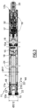
- the motorized drive device 5 comprises an electromechanical actuator 11, as illustrated in Fig. Figure 3 .
- the screen 2 of the concealment device 3 is wound on the winding tube 4 driven by the motorized drive device 5.
- the screen 2 is movable between a rolled up position, in particular high, and an unrolled position , especially bass.
- the screen 2 of the concealment device 3 is a closing, concealment and/or sun protection screen, winding and unrolling around the winding tube 4, the internal diameter of which is significantly greater than the external diameter of the electromechanical actuator 11, so that the electromechanical actuator 11 can be inserted into the winding tube 4, during the assembly of the concealment device 3.
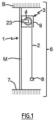
- the concealment device 3 comprises a holding device 9, 23.
- the holding device 9, 23 may comprise two supports 23.
- a support 23 is arranged at each end of the winding tube 4, in an assembled configuration of the concealment device 3.
- the winding tube 4 is held by means of the supports 23. Only one of the supports 23 is visible at the figure 1 .
- the supports 23 make it possible to mechanically connect the concealment device 3 to the structure of building B, in particular to a wall M of building B.
- the holding device 9, 23 may comprise a box 9.
- the winding tube 4 and at least part of the screen 2 are housed inside the box 9, in the assembled configuration of the device concealment 3.
- the box 9 is arranged above the opening 1, or even in the upper part of the opening 1.
- the supports 23 are also housed inside the box 9.
- the winding tube 4 is held via the box 9, in particular via the cheeks 10 of the box 9, without using supports, such as the supports 23 mentioned above.
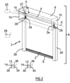
- the concealment device 3 can also comprise two lateral slides 26, as illustrated in figure 2 .
- Each side slide 26 comprises a groove 29.
- Each groove 29 of one of the side slides 26 cooperates, in other words is configured to cooperate, with a side edge 2a of the screen 2, in the assembled configuration of the concealment device 3 , so as to guide the screen 2, during the winding and unwinding of the screen 2 around the winding tube 4.
- the electromechanical actuator 11 is, for example, of the tubular type. This makes it possible to rotate the winding tube 4 around an axis of rotation X, so as to unwind or roll up the screen 2 of the concealment device 3.
- the screen 2 can be rolled up and unrolled on the winding tube 4.
- the electromechanical actuator 11 is inserted into the winding tube 4.
- the concealment device 3 also includes a load bar 8 to exert tension on the screen 2.
- the roll-up blind which forms the concealment device 3, comprises a canvas, forming the screen 2 of the roll-up blind 3.
- a first end of the screen 2, in particular the upper end of the screen 2, in the assembled configuration of the concealment device 3, is fixed to the winding tube 4.
- a second end of the screen 2, in particular the lower end of the screen 2, in the assembled configuration of the concealment device 3, is fixed to the load bar 8.
- the canvas forming the screen 2 is made from a textile material.
- the first end of the screen 2 has a hem through which a rod, in particular made of plastic material, is placed.
- This hem produced at the first end of the screen 2 is obtained by means of a seam of the canvas forming the screen 2.
- the hem and the rod located at the first end of the screen 2 are inserted by sliding into a groove provided on the external face of the winding tube 4, in particular over the entire length of the winding tube 4, of so as to secure the screen 2 with the winding tube 4 and to be able to wind and unwind the screen 2 around the winding tube 4.
- the rolled up position corresponds to a predetermined upper end position, or to the pressing of the load bar 8 of the screen 2 against an edge of a box 9 of the rollable blind 3
- the lower unrolled position corresponds to a predetermined lower end position, or to the pressing of the load bar 8 of the screen 2 against a threshold 7 of the opening 1, or else to the complete progress of screen 2.
- the motorized drive device 5 is controlled by a control unit.
- the control unit can be, for example, a local control unit 12 or a central control unit 13.
- the local control unit 12 can be connected, in a wired or non-wired connection, with the central control unit 13.
- the central control unit 13 can control the local control unit 12, as well as other similar local control units distributed throughout the building.
- the motorized drive device 5 is preferably configured to execute the commands for unwinding or winding the screen 2 of the concealment device 3, which can be issued, in particular, by the local control unit 12 or the central control unit 13.
- the installation 6 comprises either the local control unit 12, or the central control unit 13, or the local control unit 12 and the central control unit 13.
- the electromechanical actuator 11 comprises an electric motor 16.
- the electric motor 16 comprises a rotor and a stator, not shown, positioned coaxially around the axis of rotation motorized drive 5.
- Means for controlling the electromechanical actuator 11, allowing the movement of the screen 2 of the concealment device 3, comprise at least one electronic control unit 15.
- This electronic control unit 15 is capable of putting the motor into operation electrical 16 of the electromechanical actuator 11, and, in particular, allow the supply of electrical energy to the electric motor 16.
- the electronic control unit 15 controls, in particular, the electric motor 16, so as to open or close the screen 2, as described previously.
- the means for controlling the electromechanical actuator 11 comprise hardware and/or software means.
- the hardware means may include at least one microcontroller, not shown.
- the electronic control unit 15 also comprises a first communication module 27, as illustrated in figure 2 , in particular for receiving control orders, the control orders being issued by an order transmitter, such as the local control unit 12 or the central control unit 13, these orders being intended to control the device motorized drive 5.
- a first communication module 27 as illustrated in figure 2 , in particular for receiving control orders, the control orders being issued by an order transmitter, such as the local control unit 12 or the central control unit 13, these orders being intended to control the device motorized drive 5.
- the first communication module 27 of the electronic control unit 15 is of the wireless type.
- the first communication module 27 is configured to receive radio control orders.
- the first communication module 27 can also allow the reception of control orders transmitted by wired means.
- the electronic control unit 15, the local control unit 12 and/or the central control unit 13 can be in communication with a meteorological station located inside the building B or remote outside the building.
- building B including, in particular, one or more sensors that can be configured to determine, for example, a temperature, a brightness, or even a wind speed, in the case where the meteorological station is remote outside of building B.
- the electronic control unit 15, the local control unit 12 and/or the central control unit 13 can also be in communication with a server 28, as illustrated in Fig. figure 2 , so as to control the electromechanical actuator 11 according to data made available remotely by via a communications network, in particular an internet network that can be connected to the server 28.
- a communications network in particular an internet network that can be connected to the server 28.
- the electronic control unit 15 can be controlled from the local 12 or central 13 control unit.
- the local 12 or central 13 control unit is provided with a control keyboard.
- the control keyboard of the local or central control unit 12 or central 13 comprises one or more selection elements 14 and, optionally, one or more display elements 34.
- the selection elements may include push buttons and/or sensitive keys.
- the display elements may include light-emitting diodes and/or an LCD display (acronym for the Anglo-Saxon term “Liquid Crystal Display”) or TFT (acronym for the Anglo-Saxon term “Thin Film Transistor”).
- the selection and display elements can also be carried out using a touch screen.
- the local or central control unit 12 comprises at least one second communication module 36.
- the second communication module 36 of the local or central control unit 12 or central 13 is configured to emit, in other words emits, control orders, in particular by wireless means, for example radio, or by wired means .
- the second communication module 36 of the local or central control unit 12 or central 13 can also be configured to receive, in other words receive, control orders, in particular via the same means.
- the second communication module 36 of the local control unit 12 or central control unit 13 is configured to communicate, in other words communicate, with the first communication module 27 of the electronic control unit 15.
- the second communication module 36 of the local or central control unit 12 or central 13 exchanges control orders with the first communication module 27 of the electronic control unit 15, either monodirectionally or bidirectionally.
- the local control unit 12 is a control point, which can be fixed or nomadic.
- a fixed control point can be a control box intended to be fixed on a facade of a wall of building B or on a face of a frame of a window or a door.
- a portable control point can be a remote control, a smartphone or a tablet.
- the local control unit 12 or central 13 also includes a controller 35.
- the motorized drive device 5, in particular the electronic control unit 15, is preferably configured to execute movement control orders, in particular closing as well as opening, of the screen 2 of the device. concealment 3. These control orders can be issued, in particular, by the local control unit 12 or by the central control unit 13.
- the motorized drive device 5 can be controlled by the user, for example by receiving a control order corresponding to pressing one or more of the selection elements 14 of the local control unit 12 or central 13.
- the motorized drive device 5 can also be controlled automatically, for example by receiving a control order corresponding to at least one signal coming from at least one sensor and/or to a signal coming from a clock of the electronic control unit 15, in particular of the microcontroller.
- the sensor and/or the clock can be integrated into the local control unit 12 or the central control unit 13.
- the electromechanical actuator 11 comprises a casing 17, in particular tubular.
- the electric motor 16 is mounted inside the casing 17, in an assembled configuration of the electromechanical actuator 11, in particular according to a first and a second mounting configuration of a torque support 21 relative to the casing 17.
- the casing 17 of the electromechanical actuator 11 is of cylindrical shape, in particular of revolution.
- the casing 17 is made of a metallic material.
- the material of the electromechanical actuator housing is not restrictive and may be different. It may be, in particular, a plastic material.
- the electromechanical actuator 11 comprises at least one battery 24.
- the battery 24 is arranged inside the casing 17, in the assembled configuration of the electromechanical actuator 11, in particular according to the first mounting configuration of the torque support 21 relative to the casing 17.
- the electromechanical actuator 11 is supplied with electrical energy by means of the battery 24.
- the electromechanical actuator 11 comprises an electrical power cable 18 allowing the supply of electrical energy to the electronic control unit 15 and the electric motor 16, in particular from the battery 24.
- the battery 24 is of the rechargeable type.
- the battery 24 comprises one or more energy storage elements, not shown.
- the energy storage elements of the battery 24 can be, in particular, rechargeable accumulators or even rechargeable batteries.
- the motorized drive device 5 and, in particular, the electronic control unit 15, comprises charging elements configured to charge the battery 24 from the electrical energy supplied by an external electrical power source 25 , as illustrated in figure 2 .
- the external electrical power source 25 is a charger that can be plugged into a wall electrical outlet, so as to recharge the battery 24 from a mains power supply network.
- the external electrical power source 25 is an auxiliary battery, so as to recharge the battery 24.
- the battery 24 can be recharged by means of the auxiliary battery forming the external electrical power source 25, in particular in the case where the concealment device 3 is far from a wall electrical outlet.
- the electronic control unit 15 comprises a first electronic card 15a and a second electronic card 15b.
- the first electronic card 15a is configured to control the electric motor 16.
- the second electronic card 15b is configured to, in particular, allow the recharging of the battery 24, by means of an electrical connector, not shown, and , optionally, access settings and/or configuration functions of the electromechanical actuator 11, by means of selection and, possibly, display elements, not shown.
- the loading elements are arranged at the level of the second electronic card 15b.
- the electromechanical actuator 11 also comprises a reduction gear 19 and an output shaft 20.
- the reducer 19 comprises at least one reduction stage.
- the reduction stage can be an epicyclic type gear train.
- the type and number of reduction stages of the gearbox are not limiting.
- the electromechanical actuator 11 also includes a brake 32.
- the brake 32 can be a spring brake, a cam brake or an electromagnetic brake.
- the reducer 19 and, optionally, the brake 32 are arranged inside the casing 17 of the electromechanical actuator 11, in the assembled configuration of the electromechanical actuator 11, in particular according to the first and second mounting configurations of the torque support 21 relative to the casing 17.
- the electromechanical actuator 11 may also include an end of stroke and/or obstacle detection device, which may be mechanical or electronic.
- the winding tube 4 is rotated around the axis of rotation
- the first pivot connection is made at a first end of the winding tube 4 by means of a crown, not shown, inserted around a first end 17a of the casing 17 of the electromechanical actuator 11.
- the crown allows thus to achieve a level.
- the second pivot connection, not shown, is made at a second end of the winding tube 4.
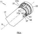
- the electromechanical actuator 11 includes the torque support 21, which can also be called “actuator head”.
- the torque support 21 is arranged at the first end 17a of the casing 17 of the electromechanical actuator 11, in the assembled configuration of the electromechanical actuator 11, in particular according to the first and second mounting configurations of the torque support 21 relative to casing 17.
- the torque support 21 makes it possible to take up the forces exerted by the electromechanical actuator 11 and, in particular, to ensure the resumption of the forces exerted by the electromechanical actuator 11, in particular the torque exerted by the electromechanical actuator 11, by the structure of the building B.
- the torque support 21 advantageously makes it possible to take up, in addition, the forces exerted by the winding tube 4, in particular the weight of the winding tube 4, of the electromechanical actuator 11 and of the screen 2, and to ensure the recovery of these efforts by the structure of building B.
- the torque support 21 of the electromechanical actuator 11 makes it possible to fix the electromechanical actuator 11 on the holding device 9, 23, in particular to one of the supports 23 or to one of the cheeks 10 of the box 9 .
- the torque support 21 projects at the level of the first end 17a of the casing 17 of the electromechanical actuator 11, in particular the end 17a of the casing 17 receiving the crown.
- the crown constitutes, in other words is configured to constitute, a bearing for guiding the rotation of the winding tube 4, in the assembled configuration of the concealment device 3.
- the torque support 21 of the electromechanical actuator 11 can also make it possible to close the first end 17a of the casing 17.
- the torque support 21 of the electromechanical actuator 11 can make it possible to support at least part of the electronic control unit 15.
- the torque support 21 comprises a first part 21a and a second part 21b.
- the first part 21a of the torque support 21 is configured to cooperate, in other words cooperates, with the casing 17 of the electromechanical actuator 11, in particular in the assembled configuration of the electromechanical actuator 11 and, more particularly, according to the first and second mounting configurations of the torque support 21 relative to the casing 17.
- the second part 21b of the torque support 21 is configured to cooperate, in other words cooperates, with the holding device 9, 23, in particular in the assembled configuration of the electromechanical actuator 11 in the installation 6 and, more particularly, according to the first mounting configuration of the torque support 21 relative to the casing 17.
- the torque support 21 comprising the first and second parts 21a, 21b in a single piece makes it possible to improve the rigidity of the torque support 21.
- At least a portion of the first part 21a of the torque support 21 is of generally cylindrical shape and is arranged inside the casing 17 of the electromechanical actuator 11, in the assembled configuration of the electromechanical actuator 11, in particular according to the first and second mounting configurations of the torque support 21 relative to the casing 17.
- an outer diameter ⁇ 212 of at least a portion of the second part 21b of the torque support 21 is greater than an outer diameter ⁇ 17 of the casing 17 of the electromechanical actuator 11.
- the torque support 21 comprises a stop 33 configured to cooperate, in other words which cooperates, with the casing 17, at the first end 17a of the casing 17, in the assembled configuration of the electromechanical actuator 11, in particular according to the first mounting configuration of the torque support 21 relative to the casing 17.
- the stop 33 of the torque support 21 makes it possible to limit the penetration of the first part 21a of the torque support 21 into the casing 17, in the direction of the axis of rotation X.
- the stop 33 of the torque support 21 delimits the first and second parts 21 a, 21b of the torque support 21 relative to each other.
- the first part 21a of the torque support 21 is arranged inside the casing 17 of the electromechanical actuator 11, following the fitting of the torque support 21 inside the casing 17, up to the stop 33, in the assembled configuration of the electromechanical actuator 11, in particular according to the first mounting configuration of the torque support 21 relative to the casing 17.
- the stop 33 of the torque support 21 is made in the form of a shoulder and, more particularly, in the form of a collar, in particular of cylindrical shape and with a rectilinear generator.
- the electronic control unit 15 can be supplied with electrical energy by means of the electrical power cable 18.
- the electronic control unit 15 can be arranged at least partly inside the casing 17 of the electromechanical actuator 11.
- the electronic control unit 15 can be arranged at least partly outside the casing 17 of the electromechanical actuator 11 and, in particular, mounted on one of the two supports 23, on one of the cheeks 10 of the box 9 or in the torque support 21.
- the first electronic card 15a of the electronic control unit 15 is arranged inside the casing 17 of the electromechanical actuator 11.
- the second electronic card 15b is arranged inside the torque support 21 of the electromechanical actuator 11.
- the torque support 21 comprises a cover 22.
- the second electronic card 15b is arranged inside a housing formed between the second part 21b of the torque support 21 and the cover 22.
- the torque support 21 comprises at least one button, not shown.
- buttons can make it possible to adjust the electromechanical actuator 11 through one or more configuration modes, to pair one or more control units 12, 13 with the electromechanical actuator 11, to reset one or more several parameters, which can be, for example, an end position, to reset the paired control unit(s) 12, 13 or even to control the movement of the screen 2.
- the torque support 21 includes a single button.
- the number of torque support buttons is not limiting and may be different. It may, in particular, be greater than or equal to two.
- the torque support 21 comprises at least one display device, not shown, so as to allow a visual indication, which may be, for example, a state of charge of the battery 24.
- the display device comprises at least one lighting source, not shown, in particular a light-emitting diode, mounted on the second electronic card 15b and, optionally, a transparent or translucent cover and/or a light guide, for allow the passage of light emitted by the source lighting.
- a lighting source not shown, in particular a light-emitting diode, mounted on the second electronic card 15b and, optionally, a transparent or translucent cover and/or a light guide, for allow the passage of light emitted by the source lighting.
- the torque support 21 comprises a single display device.
- the number of display devices is not limiting and may be different. It may, in particular, be greater than or equal to two.
- the output shaft 20 of the electromechanical actuator 11 is arranged inside the winding tube 4 and at least partly outside the casing 17 of the electromechanical actuator 11.
- one end of the output shaft 20 projects relative to the casing 17 of the electromechanical actuator 11, in particular relative to a second end 17b of the casing 17 opposite the first end 17a.
- the output shaft 20 of the electromechanical actuator 11 is configured to rotate a connecting element, not shown, connected to the winding tube 4.
- the connecting element is made in the form of a wheel .
- the electric motor 16 and the gearbox 19 rotate the output shaft 20.
- the output shaft 20 of the electromechanical actuator 11 rotates the winding tube 4 via the connecting element.
- the winding tube 4 rotates the screen 2 of the concealment device 3, so as to open or close the opening 1.
- the casing 17 comprises at least one mounting element 37.
- the or each mounting element 37 of the casing 17 can also be called “indexing element” of the casing 17.
- the or each mounting element 37 of the casing 17 is provided at the level of the first end 17a of the casing 17.
- the casing 17 includes two mounting elements 37.
- the two mounting elements 37 of the casing 17 are arranged at an angle of 180° relative to each other, around the axis of rotation X. In other words, the two mounting elements 37 of the casing 17 are diametrically opposed to the axis of rotation X.
- the number and angular position of the casing mounting elements are not limiting and may be different.
- the housing mounting elements may be one or more in number and, for example, three in number and arranged at an angle of 120° to each other, around the axis of rotation.
- each mounting element 37 of the casing 17 is produced by a recessed zone of the casing 17, in other words by a deformation of the external surface of the casing 17 in the direction of the axis of rotation X.
- the or each mounting element 37 of the casing 17 can also be called “third mounting element”.
- the torque support 21, in particular the first part 21a of the torque support 21, comprises at least one first mounting element 38 and at least one second mounting element 39.
- the or each first mounting element 38 of the torque support 21 can also be called “first indexing element” of the torque support 21.
- the or each second mounting element 39 of the torque support 21 can also be called “second indexing element” of the torque support 21.
- the torque support 21 comprises two first mounting elements 38 and two second mounting elements 39.
- the two first mounting elements 38 of the torque support 21 are arranged at an angle of 180° relative to each other. other, around the axis of rotation 21 are arranged at an angle of 180° relative to each other, around the axis of rotation axis of rotation
- the number and angular position of the first and second mounting elements of the torque support are not limiting and may be different and, more particularly, are dependent on the number of mounting elements of the housing.
- the first and second mounting elements of the torque support can be respectively one in number or strictly greater than two and, for example, three in number and arranged at an angle of 120° relative to each other , around the axis of rotation.
- each of the first and second mounting elements 38, 39 of the torque support 21 and the or each mounting element 37 of the casing 17 are press-fit mounting elements. Furthermore, each of the first and second mounting elements 38, 39 of the torque support 21 is configured to cooperate, in other words cooperates, with the or one of the mounting elements 37 of the casing 17 by cooperation of shapes.
- each first mounting element 38 of the torque support 21 is produced by a hollow zone of the torque support 21, in other words by a deformation in the direction of the axis of rotation X.
- each second mounting element 39 of torque support 21 is produced by a hollow zone of the torque support 21, in other words by a deformation in the direction of the axis of rotation X.
- first mounting elements 38 are identical to each other and the second mounting elements 39 are identical to each other.
- Each first mounting element 38 of the torque support 21 is configured to be mounted, in other words is mounted, with one of the mounting elements 37 of the casing 17, according to the first mounting configuration of the torque support 21 relative to the casing 17.
- the first mounting configuration corresponds to a functional assembly configuration of the electromechanical actuator 11.
- the functional assembly configuration of the electromechanical actuator 11 corresponds to a final assembly configuration of the electromechanical actuator 11 in which the electromechanical actuator 11 is capable of being put into service in the installation 6, in other words assembled and configured to rotate the winding tube 4 of the concealment device 3.
- the torque support 21 is oriented and locked in rotation around the axis of rotation mounting 37 of the casing 17.
- Each second mounting element 39 of the torque support 21 is different from a first mounting element 38 of the torque support 21.
- each second mounting element 39 has a shape different from that of a first mounting element 38.
- Each second mounting element 39 of the torque support 21 is configured to be mounted, in other words is mounted, with one of the mounting elements 37 of the casing 17, according to the second mounting configuration of the torque support 21 relative to the casing 17.
- the second mounting configuration corresponds to a control configuration of the electromechanical actuator 11.
- the torque support 21 is oriented and locked in rotation around the axis of rotation mounting 37 of the casing 17.
- the or each first mounting element 38 of the torque support 21 is different from the or each second mounting element 39 of the torque support 21, so that, according to the first mounting configuration of the torque support 21 relative to the casing 17, the or each first mounting element 38 of the torque support 21 is mounted, in other words is configured to be mounted, with the or one of the elements mounting 37 of the casing 17 to guarantee a functional assembly configuration of the electromechanical actuator 11 and that, according to the second mounting configuration of the torque support 21 relative to the casing 17, the or each second mounting element 39 of the support torque 21 is mounted, in other words is configured to be mounted, with the or one of the mounting elements 37 of the casing 17 to guarantee a control configuration of the electromechanical actuator 11.
- such an electromechanical actuator 11 makes it possible to guarantee mounting of the torque support 21 relative to the casing 17 in at least a first position, in a first functional assembly configuration of the electromechanical actuator 11, and in at least a second position, in a second additional assembly configuration of the electromechanical actuator 11 which is that of controlling the electromechanical actuator 11 and which is therefore different from the first functional assembly configuration of the electromechanical actuator 11.
- the torque support 21 can thus be mounted relative to the casing 17 in at least two distinct positions, in particular according to the first and second mounting configurations, of which a first mounting position of the torque support 21 relative to the casing 17 is a functional assembly position of the electromechanical actuator 11, where the torque support 21 is configured to be fixed to the casing 17, and a second mounting position of the torque support 21 relative to the casing 17 is a control position of the electromechanical actuator 11, where the control position is different from the functional assembly position of the electromechanical actuator 11.
- an electromechanical actuator 11 allows the mounting of the torque support 21 relative to the casing 17 according to the first and second mounting configurations on the same station of a manufacturing unit, so as to minimize assembly time of the electromechanical actuator 11 and to limit investments to obtain the manufacturing unit.
- the second mounting configuration corresponding to a control configuration of the electromechanical actuator 11, is intended to be used in the factory to carry out a control of the electromechanical actuator 11.
- the second mounting configuration corresponding to a control configuration of the electromechanical actuator 11, is intended to be used in the factory to measure the intensity of an electric current circulating in the electromechanical actuator 11, in particular when it is configured to be equipped with the battery 24.
- the intensity measurement of the electromechanical actuator 11 is implemented before assembling the battery 24 inside of the casing 17 and before the electrical connection of the battery 24 to the electronic control unit 15, in particular to the first electronic card 15a, by means of the electrical power cable 18.
- an intensity measurement of the electromechanical actuator 11 can be implemented in the absence of the battery 24 and when the torque support 21, in particular the first part 21a of the torque support 21, is partially inserted in the casing 17, in particular according to the second mounting configuration of the torque support 21 relative to the casing 17.
- measuring the intensity of the electromechanical actuator 11 makes it possible to check the compatibility of the battery 24 to be assembled in the electromechanical actuator 11 with the electronic control unit 15 and the electric motor 16, before assembly. of the battery 24 inside the casing 17 and before the electrical connection of the battery 24 to the electronic control unit 15, in particular to the first electronic card 15a, by means of the electrical power cable 18.
- the transition from the first mounting configuration to the second mounting configuration, and vice versa is implemented by a rotational movement R, around the axis of rotation X, of the torque support 21 relative to the casing 17 .
- the torque support 21 is configured to be oriented, in other words is oriented, relative to the casing 17, around the axis of rotation X of the electromechanical actuator 11 and in the first mounting configuration, with a first orientation of the support torque 21 relative to the casing 17.
- the torque support 21 is also configured to be oriented, in other words is oriented, relative to the casing 17, around the axis of rotation X and in the second mounting configuration, with a second orientation of the torque support 21 relative to the casing 17.
- the first and second orientations of the torque support 21 relative to the casing 17 are offset relative to each other, around the axis of rotation X, of a predetermined non-zero angular value ⁇ .
- the predetermined angular value ⁇ is included in a range of values extending between 20° and 160° and is preferably of the order of 90°.
- the first and second orientations of the torque support 21 relative to the casing 17 are determined by an angular positioning of the or each first mounting element 38 of the torque support 21 relative to the or each second mounting element 39 of the support of torque 21, around the axis of rotation X.
- the or each second mounting element 39 of the torque support 21 is configured to be housed, in other words is housed, inside the casing 17, according to the first mounting configuration.
- the or each second mounting element 39 of the torque support 21 is offset relative to the or one of the mounting elements 37 of the casing 17, around the axis of rotation X, so as not to interfere with the or one of the mounting elements 37 of the casing 17.
- the or each first mounting element 38 of the torque support 21 is configured to be housed, in other words is housed, inside the casing 17, according to the second mounting configuration.
- the or each first mounting element 38 of the torque support 21 is offset relative to the or one of the mounting elements 37 of the casing 17, around the axis of rotation X, so as not to interfere with the or one of the mounting elements 37 of the casing 17.
- the first mounting element 38 of the torque support 21 comprises a first stop 43.
- the second mounting element 39 of the torque support 21 comprises a second stop 44.
- the casing 17 comprises an edge 45 at the first end 17a of the casing 17.
- the edge 45 of the casing 17 is configured to be placed in support, in other words is placed in support, with the first stop 43 of the first mounting element 38 of the torque support 21, in the first mounting configuration, of so that the torque support 21, in particular the first part 21a of the torque support 21, is inserted partly inside the casing 17 at a first predetermined distance L1 parallel to the axis of rotation X of the electromechanical actuator 11.
- the edge 45 of the casing 17 is also configured to be placed in support, in other words is placed in support, with the second stop 44 of the second mounting element 39 of the torque support 21, in the second mounting configuration, so that the torque support 21, in particular the first part 21a of the torque support 21, is inserted partly inside the casing 17 at a second predetermined distance L2 parallel to the axis of rotation predetermined distance L1 is greater than the second predetermined distance L2.
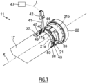
- each of the first and second predetermined distances L1, L2 for insertion of the torque support 21 inside the casing 17, along the axis of rotation X and in each of the first and second mounting configurations is defined by a length between the edge 45 of the casing 17, at the level of the first end 17a of the casing 17, and an edge 46 of the torque support 21, in particular of the first part 21a of the torque support 21, at the level of an end 21c torque support 21 configured to be inserted into the casing 17.
- the torque support 21 comprises at least one notch 40.
- the notch 40 of the torque support 21 is configured to be closed by the casing 17, in the first mounting configuration, and to be unobstructed relative to the casing 17, that is to say not being totally obstructed by it, in the second mounting configuration.
- the notch 40 is configured to allow the control of the electromechanical actuator 11, in particular the measurement of intensity of the latter, when the torque support 21 is mounted relative to the casing 17, according to the second mounting configuration .
- the notch 40 of the torque support 21 can also be called “opening", in particular through, or "notch".
- the notch 40 of the torque support 21 is formed in the or each second mounting element 39 of the torque support 21.
- the notch 40 of the torque support 21 is configured for the passage of at least one electrical power cable 41, from the inside of the casing 17 to the outside of the casing 17, in the second configuration of assembly.
- the electrical power cable 41 extends, on the one hand, inside the casing 17 and, on the other hand, outside the casing 17 and crosses the notch 40 of the torque support 21.
- the electronic control unit 15, in particular the first electronic card 15a is configured to be electrically connected to a control tool 47 by an electrical connection L, in the second mounting configuration.
- the electrical connection L between the electronic control unit 15, in particular the first electronic card 15a, and the control tool 47 is implemented by the electrical supply cable 41 extending through the notch 40 made in the torque support 21.
- the electrical supply cable 41 is configured to be electrically connected, in other words is electrically connected, to the electronic control unit 15, in particular to the first electronic card 15a of the electronic control unit 15, in the first and second mounting configurations.
- the electrical power cable 41 comprises an electrical connector 42.
- the electrical connector 42 of the electrical power cable 41 is configured to cooperate with an electrical connector, not shown, of the control tool 47.
- the battery 24 is inserted inside the casing 17 then the torque support 21 is assembled with the casing 17 according to the first mounting configuration.
- the battery 24 includes an electrical connector, not shown. Furthermore, the electrical connector of the battery 24 is configured to be electrically connected, in other words is electrically connected, to the electrical connector 42 of the electrical power cable 41, prior to the insertion of the battery 24 inside the casing 17.
- the electrical connector 42 of the electrical power cable 41 makes it possible, on the one hand, to supply electrical energy to the electronic control unit 15, in particular the first electronic card 15a, and the electric motor 16, according to the first mounting configuration, and, on the other hand, to implement the control of the electromechanical actuator 11, according to the second mounting configuration.
- the casing 17 and the torque support 21 are configured to be fixed together, in other words are fixed together, by means of at least one fixing element 48, only according to the first mounting configuration.
- the fixing of the casing 17 with the torque support 21 makes it possible to block the torque support 21 in translation relative to the casing 17.
- the fixing of the casing 17 with the torque support 21 is implemented according to the first mounting configuration and not according to the second mounting configuration.
- the second mounting configuration is a temporary assembly configuration of the torque support 21 with the casing 17.
- the fixing of the casing 17 and the torque support 21, according to the first mounting configuration is implemented following the insertion of the battery 24 inside the casing 17.
- the fixing element(s) 48 of the casing 17 with the torque support 21 are screw fixing elements, in particular fixing screws which can be, for example, self-tapping.
- housing fixing elements with the torque support is not limiting and may be different. These may be, for example, fastening elements by riveting or by elastic snap-fastening.
- the casing 17 comprises at least one through hole 49 of a fixing element 48.
- the torque support 21 comprises at least one through hole 49. fixing 50 of a fixing element 48.
- the electromechanical actuator 11 comprises two fixing elements 48.
- the casing 17 comprises two through holes 49.
- the torque support 21 comprises two fixing holes 50. The number of through holes 49 of the casing 17 and of fixing holes 50 of the torque support 21 is dependent on the number of fixing elements 48.
- the number of fixing elements, housing passage holes and torque support fixing holes is not limiting and may be different. It can be, for example, one or strictly greater than two.
- each fixing screw 48 passes through one of the through holes 49 of the casing 17 and is screwed into one of the fixing holes 50 of the torque support 21.
- At least one through hole 49 of the casing 17 is provided in a mounting element 37 of the casing 17.
- at least one fixing hole 50 of the torque support 21 is provided in a first mounting element 38 of the support of torque 21.
- the number of through holes 49 of the casing 17 and of fixing holes 50 of the torque support 21 is dependent on the number of first mounting elements 38 of the torque support 21, and vice versa.
- each through hole 49 of the casing 17 is provided in one of the mounting elements 37 of the casing 17.
- each fixing hole 50 of the torque support 21 is provided in one of the first mounting elements 38 of the torque support 21.
- the first torque bracket mounting member is different from the second torque bracket mounting member, such that the first torque bracket mounting member is mounted with the crankcase mounting member for ensure a functional assembly configuration of the electromechanical actuator, in the first mounting configuration of the torque bracket relative to the housing, and that the second mounting element of the torque bracket is mounted with the mounting element of the housing to guarantee a control configuration of the electromechanical actuator, in the second mounting configuration of the torque support relative to the housing.
- such an electromechanical actuator makes it possible to guarantee mounting of the torque support relative to the casing in at least a first position, in a first functional assembly configuration of the electromechanical actuator, and in at least a second position, in a second assembly configuration of the additional electromechanical actuator which is that of controlling the electromechanical actuator and which is therefore different from the first functional assembly configuration of the electromechanical actuator.
- the electromechanical actuator 11 is inserted in a rail, in particular of square or rectangular section, which can be opened at one or both ends, in the assembled configuration of the concealment device 3.
- the electromechanical actuator 11 can be configured to drive a drive shaft on which cords for moving and/or orienting the screen 2 are wound.
- the electromechanical actuator 11 is supplied with electrical energy by a sector electrical energy supply network.
Landscapes
- Engineering & Computer Science (AREA)
- Structural Engineering (AREA)
- Architecture (AREA)
- Civil Engineering (AREA)
- Operating, Guiding And Securing Of Roll- Type Closing Members (AREA)
- Connection Of Motors, Electrical Generators, Mechanical Devices, And The Like (AREA)
- Power-Operated Mechanisms For Wings (AREA)
Claims (11)
- Elektromechanischer Aktuator (11) für eine Schließ-, Verdunkelungs- oder Sonnenschutzanlage (6),wobei der elektromechanische Aktuator (11) mindestens Folgendes umfasst:- einen Elektromotor (16),- ein Gehäuse (17), wobei der Elektromotor (16) innerhalb des Gehäuses (17) in einer zusammengebauten Konfiguration des elektromechanischen Aktuators (11) montiert ist, wobei das Gehäuse (17) mindestens ein Montageelement (37) umfasst, und- eine Drehmomentstütze (21), wobei die Drehmomentstütze (21) an einem ersten Ende (17a) des Gehäuses (17) in der zusammengebauten Konfiguration des elektromechanischen Aktuators (11) angeordnet ist, wobei die Drehmomentstütze (21) mindestens ein erstes Montageelement (38) umfasst,das erste Montageelement (38) der Drehmomentstütze (21) so konfiguriert ist, dass es mit dem Montageelement (37) des Gehäuses (17) in einer ersten Montagekonfiguration der Drehmomentstütze (21) in Bezug auf das Gehäuse (17) montiert werden kann, wobei die erste Montagekonfiguration einer funktionalen Montagekonfiguration des elektromechanischen Aktuators (11) entspricht, dadurch gekennzeichnet dass die Drehmomentstütze (21) ferner mindestens ein zweites Montageelement (39) umfasst, wobei das zweite Montageelement (39) der Drehmomentstütze (21) von dem ersten Montageelement (38) der Drehmomentstütze (21) verschieden ist,dass das zweite Montageelement (39) der Drehmomentstütze (21) so konfiguriert ist, dass es mit dem Montageelement (37) des Gehäuses (17) gemäß einer zweiten Montagekonfiguration der Drehmomentstütze (21) in Bezug auf das Gehäuse (17) montiert werden kann, wobei die zweite Montagekonfiguration einer Steuerkonfiguration des elektromechanischen Aktuators (11) entspricht,dass die Drehmomentstütze (21) so konfiguriert ist, dass sie in Bezug auf das Gehäuse (17) um eine Drehachse (X) des elektromechanischen Aktuators (11) und in der ersten Montagekonfiguration mit einer ersten Ausrichtung der Drehmomentstütze (21) in Bezug auf das Gehäuse (17) orientiert ist,dass die Drehmomentstütze (21) auch so konfiguriert ist, dass sie in Bezug auf das Gehäuse (17) um die Drehachse (X) und in der zweiten Montagekonfiguration mit einer zweiten Ausrichtung der Drehmomentstütze (21) in Bezug auf das Gehäuse (17) ausgerichtet ist, unddass die erste und zweite Ausrichtung der Drehmomentstütze (21) in Bezug auf das Gehäuse (17) um die Drehachse (X) um einen vorbestimmten Winkelwert (α) ungleich Null gegeneinander verschoben sind.
- Elektromechanischer Aktuator (11) für eine Schließ-, Verdunkelungs- oder Sonnenschutzanlage (6) nach Anspruch 1, dadurch gekennzeichnet, dass die Drehmomentstütze (21) mindestens eine Kerbe (40) umfasst und dass die Kerbe (40) der Drehmomentstütze (21) so konfiguriert ist, dass sie so ausgebildet ist, dass sie in der ersten Montagekonfiguration durch das Gehäuse (17) verschlossen ist und in der zweiten Montagekonfiguration in Bezug auf das Gehäuse (17) nicht verschlossen ist.
- Elektromechanischer Aktuator (11) für eine Schließ-, Verdunkelungs- oder Sonnenschutzanlage (6) nach Anspruch 2, dadurch gekennzeichnet, dass die Kerbe (40) der Drehmomentstütze (21) in dem zweiten Montageelement (39) der Drehmomentstütze (21) ausgebildet ist.
- Elektromechanischer Aktuator (11) für eine Schließ-, Verdunkelungs- oder Sonnenschutzanlage (6) nach Anspruch 2 oder nach Anspruch 3, dadurch gekennzeichnet, dass die Kerbe (40) der Drehmomentstütze (21) für die Durchführung mindestens eines Stromversorgungskabels (41) von der Innenseite des Gehäuses (17) zur Außenseite des Gehäuses (17) in der zweiten Montagekonfiguration konfiguriert ist.
- Elektromechanischer Aktuator (11) für eine Schließ-, Verdunkelungs- oder Sonnenschutzanlage (6) nach einem der Ansprüche 1 bis 4, dadurch gekennzeichnet, dass die erste und zweite Ausrichtung der Drehmomentstütze (21) in Bezug auf das Gehäuse (17) durch eine Winkelpositionierung des ersten Montageelements (38) der Drehmomentstütze (21) in Bezug auf das zweite Montageelement (39) der Drehmomentstütze (21) um die Drehachse (X) bestimmt werden.
- Elektromechanischer Aktuator (11) für eine Schließ-, Verdunkelungs- oder Sonnenschutzanlage (6) nach einem der Ansprüche 1 bis 5, dadurch gekennzeichnet, dass jedes der ersten und zweiten Montageelemente (38, 39) der Drehmomentstütze (21) und das Montageelement (37) des Gehäuses (17) Einpressmontageelemente sind und dass jedes der ersten und zweiten Montageelemente (38, 39) der Drehmomentstütze (21) so konfiguriert ist, dass es mit dem Montageelement (37) des Gehäuses (17) formschlüssig zusammenwirkt.
- Elektromechanischer Aktuator (11) für eine Schließ-, Verdunkelungs- oder Sonnenschutzanlage (6) nach einem der Ansprüche 1 bis 6, dadurch gekennzeichnet, dass:- das erste Montageelement (38) der Drehmomentstütze (21) einen ersten Anschlag (43) umfasst,- das zweite Montageelement (39) der Drehmomentstütze (21) einen zweiten Anschlag (44) umfasst,- das Gehäuse (17) einen Rand (45) an dem ersten Ende (17a) des Gehäuses (17) aufweist,- der Rand (45) des Gehäuses (17) so konfiguriert ist, dass er in der ersten Montagekonfiguration an dem ersten Anschlag (43) des ersten Montageelements (38) der Drehmomentstütze (21) anliegt, so dass die Drehmomentstütze (21) um einen ersten vorbestimmten Abstand (L1) parallel zu einer Drehachse (X) des elektromechanischen Aktuators (11) teilweise in das Innere des Gehäuses (17) eingeschoben wird,- der Rand (45) des Gehäuses (17) auch so konfiguriert ist, dass er in der zweiten Montageposition an dem zweiten Anschlag (44) des zweiten Montageelements (39) der Drehmomentstütze (21) anliegt, so dass die Drehmomentstütze (21) um einen zweiten vorbestimmten Abstand (L2) parallel zur Drehachse (X) teilweise in das Innere des Gehäuses (17) eingeführt wird, und- der erste vorbestimmte Abstand (L1) größer als der zweite vorbestimmte Abstand (L2) ist.
- Elektromechanischer Aktuator (11) für eine Schließ-, Verdunkelungs- oder Sonnenschutzanlage (6) nach einem der Ansprüche 1 bis 7, dadurch gekennzeichnet, dass der elektromechanische Aktuator (11) mindestens eine Batterie (24) umfasst, wobei die Batterie (24) in der zusammengebauten Konfiguration des elektromechanischen Aktuators (11) im Inneren des Gehäuses (17) angeordnet ist.
- Elektromechanischer Aktuator (11) für eine Schließ-, Verdunkelungs- oder Sonnenschutzanlage (6) nach einem der Ansprüche 1 bis 8, dadurch gekennzeichnet, dass der elektromechanische Aktuator (11) eine elektronische Steuereinheit (15) umfasst und dass die elektronische Steuereinheit (15) so konfiguriert ist, dass sie in der zweiten Montagekonfiguration über eine elektrische Verbindung (L) mit einem Steuerwerkzeug (47) elektrisch verbunden ist.
- Elektromechanischer Aktuator (11) für eine Schließ-, Verdunkelungs- oder Sonnenschutzanlage (6) nach Anspruch 4 und nach Anspruch 9, dadurch gekennzeichnet, dass in der zweiten Montagekonfiguration die elektrische Verbindung (L) zwischen der elektronischen Steuereinheit (15) und dem Steuerwerkzeug (47) durch das Stromversorgungskabel (41) hergestellt wird, das sich durch die in der Drehmomentstütze (21) ausgebildete Kerbe (40) erstreckt.
- Schließ-, Verdunkelungs- oder Sonnenschutzanlage (6) mit einem Schirm (2), einem Wickelrohr (4) und einem elektromechanischen Aktuator (11) nach einem der Ansprüche 1 bis 10, wobei der Schirm (2) auf das Wickelrohr (4) aufwickelbar ist und das Wickelrohr (4) so angeordnet ist, dass es durch den elektromechanischen Aktuator (11) in Drehung versetzt wird.
Applications Claiming Priority (2)
| Application Number | Priority Date | Filing Date | Title |
|---|---|---|---|
| FR1905072A FR3096194B1 (fr) | 2019-05-15 | 2019-05-15 | Actionneur électromécanique et installation de fermeture, d’occultation ou de protection solaire comprenant un tel actionneur électromécanique |
| PCT/EP2020/063456 WO2020229596A1 (fr) | 2019-05-15 | 2020-05-14 | Actionneur électromécanique et installation de fermeture, d'occultation ou de protection solaire comprenant un tel actionneur électromécanique |
Publications (2)
| Publication Number | Publication Date |
|---|---|
| EP3969715A1 EP3969715A1 (de) | 2022-03-23 |
| EP3969715B1 true EP3969715B1 (de) | 2024-03-27 |
Family
ID=67957045
Family Applications (1)
| Application Number | Title | Priority Date | Filing Date |
|---|---|---|---|
| EP20725543.1A Active EP3969715B1 (de) | 2019-05-15 | 2020-05-14 | Elektromechanischer aktuator und verschluss-, abdeck- oder sonnenschutzinstallation mit solch einem elektromechanischen aktuator |
Country Status (4)
| Country | Link |
|---|---|
| US (1) | US20220228437A1 (de) |
| EP (1) | EP3969715B1 (de) |
| FR (1) | FR3096194B1 (de) |
| WO (1) | WO2020229596A1 (de) |
Families Citing this family (1)
| Publication number | Priority date | Publication date | Assignee | Title |
|---|---|---|---|---|
| US11596053B2 (en) * | 2020-10-22 | 2023-02-28 | Dell Products L.P. | Parallel printed circuit board assembly |
Family Cites Families (5)
| Publication number | Priority date | Publication date | Assignee | Title |
|---|---|---|---|---|
| FR2945314B1 (fr) * | 2009-05-05 | 2011-07-01 | Somfy Sas | Actionneur tubulaire d'entrainement d'un volet roulant |
| NL1039407C2 (en) * | 2012-02-27 | 2013-08-28 | Hunter Douglas Ind Bv | Architectural covering having a drive mechanism for extending and retracting a covering member between opposite first and second end positions. |
| WO2017051214A1 (en) * | 2015-09-23 | 2017-03-30 | Nice S.P.A. | Tubular driver for shutters |
| FR3072117B1 (fr) * | 2017-10-10 | 2019-11-08 | Somfy Activites Sa | Actionneur electromecanique tubulaire, installation domotique comprenant un tel actionneur et procede d'assemblage d'un tel actionneur |
| FR3072115B1 (fr) * | 2017-10-10 | 2019-11-08 | Somfy Activites Sa | Actionneur electromecanique tubulaire, installation domotique comprenant un tel actionneur et procede d'assemblage d'un tel actionneur |
-
2019
- 2019-05-15 FR FR1905072A patent/FR3096194B1/fr active Active
-
2020
- 2020-05-14 WO PCT/EP2020/063456 patent/WO2020229596A1/fr unknown
- 2020-05-14 US US17/610,275 patent/US20220228437A1/en active Pending
- 2020-05-14 EP EP20725543.1A patent/EP3969715B1/de active Active
Also Published As
| Publication number | Publication date |
|---|---|
| WO2020229596A1 (fr) | 2020-11-19 |
| FR3096194A1 (fr) | 2020-11-20 |
| EP3969715A1 (de) | 2022-03-23 |
| FR3096194B1 (fr) | 2021-07-16 |
| US20220228437A1 (en) | 2022-07-21 |
Similar Documents
| Publication | Publication Date | Title |
|---|---|---|
| EP3695087B1 (de) | Rohrförmiger elektromechanischer aktuator, heimautomatisierungsausrüstung mit solch einem aktuator und verfahren zur verbindung solch eines aktuators | |
| EP3695086B1 (de) | Rohrmotor, heimautomatisierung mit diesem motor und sein herstellungsverfahren | |
| WO2020025711A1 (fr) | Module mécanique de filtrage de vibrations, actionneur électromécanique comprenant un tel module mécanique de filtrage de vibrations et installation de fermeture, d'occultation ou de protection solaire comprenant un tel actionneur électromécanique | |
| EP4008876A1 (de) | Elektromechanisches stellglied und verschluss-, verdunkelungs- oder sonnenschutzanlage, die ein solches stellglied umfasst | |
| EP3803021A1 (de) | Rollladenvorrichtung für eine heimautomatisierungs- oder sonnenschutzvorrichtung in einem gebäude und zugehörige heimautomatisierungsinstallation | |
| EP3969715B1 (de) | Elektromechanischer aktuator und verschluss-, abdeck- oder sonnenschutzinstallation mit solch einem elektromechanischen aktuator | |
| EP3857014B1 (de) | Elektromechanischer aktuator mit einem modul zur filterung von vibrationen und verschluss, abdeckung oder sonnenschutzsystem mit einem solchen elektromechanischen aktuator | |
| EP4232680A1 (de) | Verfahren zur steuerung des betriebs einer beschattungsvorrichtung und zugehörige beschattungsvorrichtung | |
| EP3263821B1 (de) | Heimtechnikanlage und verfahren zur inbetriebnahme dieser anlage | |
| FR3100266A1 (fr) | Dispositif d’alimentation en énergie électrique autonome, dispositif d’entraînement motorisé, installation et fenêtre associés | |
| WO2022233708A1 (fr) | Accessoire d'un actionneur électromécanique d'un dispositif d'occultation, actionneur électromécanique comprenant un tel accessoire et dispositif d'occultation associé | |
| EP4172452A1 (de) | Beschattungsvorrichtung mit einer motorischen antriebseinrichtung | |
| EP4047170B1 (de) | Elektromechanisches stellglied, motorbetriebene antriebsvorrichtung mit einem solchen elektromechanischen stellglied und verdunkelungsvorrichtung mit einer solchen motorbetriebenen antriebsvorrichtung | |
| FR3140109A1 (fr) | Actionneur électromécanique et dispositif d’occultation comprenant un tel actionneur électromécanique | |
| WO2022148734A1 (fr) | Dispositif d'entraînement motorisé pour un dispositif d'occultation, dispositif d'occultation et procédé de commande en fonctionnement associés | |
| FR3139592A1 (fr) | Dispositif d’entraînement motorisé d’un dispositif d’occultation et dispositif d’occultation associé | |
| FR3135295A1 (fr) | Accessoire de câblage électrique à un réseau d’alimentation électrique d’un actionneur électromécanique pour un dispositif d’occultation et dispositif d’occultation associé | |
| WO2022207133A1 (fr) | Actionneur électromécanique et installation de fermeture, d'occultation ou de protection solaire comprenant un tel actionneur électromécanique | |
| WO2022253874A1 (fr) | Actionneur électromécanique d'un dispositif d'occultation et dispositif d'occultation associé | |
| FR3123678A1 (fr) | Actionneur électromécanique d’un dispositif d’occultation, dispositif d’occultation associé et procédé d’assemblage d’un tel actionneur | |
| EP3954857A1 (de) | Abdeckvorrichtung, die eine motorisierte antriebsvorrichtung umfasst | |
| EP4230835A1 (de) | Elektromechanischer aktuator und verdunkelungsvorrichtung mit solch einem elektromechanischen aktuator | |
| WO2022175518A1 (fr) | Actionneur électromécanique, dispositif d'entraînement motorisé comprenant un tel actionneur électromécanique et dispositif d'occultation comprenant un tel dispositif d'entraînement motorisé | |
| EP4345243A1 (de) | Verdunkelungsvorrichtung | |
| EP4175119A1 (de) | Motorisierte antriebsvorrichtung, verdunkelungsvorrichtung und steuerungsverfahren dafür |
Legal Events
| Date | Code | Title | Description |
|---|---|---|---|
| STAA | Information on the status of an ep patent application or granted ep patent |
Free format text: STATUS: UNKNOWN |
|
| STAA | Information on the status of an ep patent application or granted ep patent |
Free format text: STATUS: THE INTERNATIONAL PUBLICATION HAS BEEN MADE |
|
| PUAI | Public reference made under article 153(3) epc to a published international application that has entered the european phase |
Free format text: ORIGINAL CODE: 0009012 |
|
| STAA | Information on the status of an ep patent application or granted ep patent |
Free format text: STATUS: REQUEST FOR EXAMINATION WAS MADE |
|
| 17P | Request for examination filed |
Effective date: 20211112 |
|
| AK | Designated contracting states |
Kind code of ref document: A1 Designated state(s): AL AT BE BG CH CY CZ DE DK EE ES FI FR GB GR HR HU IE IS IT LI LT LU LV MC MK MT NL NO PL PT RO RS SE SI SK SM TR |
|
| RIN1 | Information on inventor provided before grant (corrected) |
Inventor name: PETITE, SEBASTIEN Inventor name: GARCIA, THOMAS Inventor name: CAILLAT, JONATHAN |
|
| DAV | Request for validation of the european patent (deleted) | ||
| DAX | Request for extension of the european patent (deleted) | ||
| GRAP | Despatch of communication of intention to grant a patent |
Free format text: ORIGINAL CODE: EPIDOSNIGR1 |
|
| STAA | Information on the status of an ep patent application or granted ep patent |
Free format text: STATUS: GRANT OF PATENT IS INTENDED |
|
| INTG | Intention to grant announced |
Effective date: 20231023 |
|
| GRAS | Grant fee paid |
Free format text: ORIGINAL CODE: EPIDOSNIGR3 |
|
| GRAA | (expected) grant |
Free format text: ORIGINAL CODE: 0009210 |
|
| STAA | Information on the status of an ep patent application or granted ep patent |
Free format text: STATUS: THE PATENT HAS BEEN GRANTED |
|
| AK | Designated contracting states |
Kind code of ref document: B1 Designated state(s): AL AT BE BG CH CY CZ DE DK EE ES FI FR GB GR HR HU IE IS IT LI LT LU LV MC MK MT NL NO PL PT RO RS SE SI SK SM TR |
|
| REG | Reference to a national code |
Ref country code: GB Ref legal event code: FG4D Free format text: NOT ENGLISH |
|
| REG | Reference to a national code |
Ref country code: CH Ref legal event code: EP |
|
| REG | Reference to a national code |
Ref country code: DE Ref legal event code: R096 Ref document number: 602020027925 Country of ref document: DE |
|
| REG | Reference to a national code |
Ref country code: IE Ref legal event code: FG4D Free format text: LANGUAGE OF EP DOCUMENT: FRENCH |
|
| PGFP | Annual fee paid to national office [announced via postgrant information from national office to epo] |
Ref country code: NL Payment date: 20240424 Year of fee payment: 5 |