EP3969715B1 - Electromechanical actuator and closure, covering or solar protection installation comprising such an electromechanical actuator - Google Patents
Electromechanical actuator and closure, covering or solar protection installation comprising such an electromechanical actuator Download PDFInfo
- Publication number
- EP3969715B1 EP3969715B1 EP20725543.1A EP20725543A EP3969715B1 EP 3969715 B1 EP3969715 B1 EP 3969715B1 EP 20725543 A EP20725543 A EP 20725543A EP 3969715 B1 EP3969715 B1 EP 3969715B1
- Authority
- EP
- European Patent Office
- Prior art keywords
- torque support
- casing
- electromechanical actuator
- configuration
- assembly
- Prior art date
- Legal status (The legal status is an assumption and is not a legal conclusion. Google has not performed a legal analysis and makes no representation as to the accuracy of the status listed.)
- Active
Links
- 238000009434 installation Methods 0.000 title claims description 31
- 238000004804 winding Methods 0.000 claims description 39
- 238000004891 communication Methods 0.000 description 14
- 239000000463 material Substances 0.000 description 5
- 230000009467 reduction Effects 0.000 description 4
- 230000001419 dependent effect Effects 0.000 description 3
- 238000003780 insertion Methods 0.000 description 3
- 230000037431 insertion Effects 0.000 description 3
- 238000005259 measurement Methods 0.000 description 3
- 238000003825 pressing Methods 0.000 description 3
- 239000003638 chemical reducing agent Substances 0.000 description 2
- 238000004146 energy storage Methods 0.000 description 2
- 238000004519 manufacturing process Methods 0.000 description 2
- 238000005096 rolling process Methods 0.000 description 2
- 230000037072 sun protection Effects 0.000 description 2
- 238000001514 detection method Methods 0.000 description 1
- 239000004973 liquid crystal related substance Substances 0.000 description 1
- 239000007769 metal material Substances 0.000 description 1
- 238000012986 modification Methods 0.000 description 1
- 230000004048 modification Effects 0.000 description 1
- 230000035515 penetration Effects 0.000 description 1
- 238000011084 recovery Methods 0.000 description 1
- 238000010079 rubber tapping Methods 0.000 description 1
- 239000004753 textile Substances 0.000 description 1
- 239000010409 thin film Substances 0.000 description 1
- 230000007704 transition Effects 0.000 description 1
- 238000013519 translation Methods 0.000 description 1
- 230000000007 visual effect Effects 0.000 description 1
Images


Classifications
-
- E—FIXED CONSTRUCTIONS
- E06—DOORS, WINDOWS, SHUTTERS, OR ROLLER BLINDS IN GENERAL; LADDERS
- E06B—FIXED OR MOVABLE CLOSURES FOR OPENINGS IN BUILDINGS, VEHICLES, FENCES OR LIKE ENCLOSURES IN GENERAL, e.g. DOORS, WINDOWS, BLINDS, GATES
- E06B9/00—Screening or protective devices for wall or similar openings, with or without operating or securing mechanisms; Closures of similar construction
- E06B9/56—Operating, guiding or securing devices or arrangements for roll-type closures; Spring drums; Tape drums; Counterweighting arrangements therefor
- E06B9/68—Operating devices or mechanisms, e.g. with electric drive
- E06B9/72—Operating devices or mechanisms, e.g. with electric drive comprising an electric motor positioned inside the roller
-
- E—FIXED CONSTRUCTIONS
- E06—DOORS, WINDOWS, SHUTTERS, OR ROLLER BLINDS IN GENERAL; LADDERS
- E06B—FIXED OR MOVABLE CLOSURES FOR OPENINGS IN BUILDINGS, VEHICLES, FENCES OR LIKE ENCLOSURES IN GENERAL, e.g. DOORS, WINDOWS, BLINDS, GATES
- E06B9/00—Screening or protective devices for wall or similar openings, with or without operating or securing mechanisms; Closures of similar construction
- E06B9/02—Shutters, movable grilles, or other safety closing devices, e.g. against burglary
- E06B9/08—Roll-type closures
- E06B9/11—Roller shutters
- E06B9/17—Parts or details of roller shutters, e.g. suspension devices, shutter boxes, wicket doors, ventilation openings
- E06B9/174—Bearings specially adapted therefor
-
- E—FIXED CONSTRUCTIONS
- E06—DOORS, WINDOWS, SHUTTERS, OR ROLLER BLINDS IN GENERAL; LADDERS
- E06B—FIXED OR MOVABLE CLOSURES FOR OPENINGS IN BUILDINGS, VEHICLES, FENCES OR LIKE ENCLOSURES IN GENERAL, e.g. DOORS, WINDOWS, BLINDS, GATES
- E06B9/00—Screening or protective devices for wall or similar openings, with or without operating or securing mechanisms; Closures of similar construction
- E06B9/24—Screens or other constructions affording protection against light, especially against sunshine; Similar screens for privacy or appearance; Slat blinds
- E06B9/40—Roller blinds
- E06B9/42—Parts or details of roller blinds, e.g. suspension devices, blind boxes
- E06B9/50—Bearings specially adapted therefor
Definitions
- the present invention relates to an electromechanical actuator comprising a torque support, intended to be mounted at least partly inside a casing of the electromechanical actuator, as well as a closing, concealment or solar protection installation. comprising a roll-up screen on a winding tube rotated by such an electromechanical actuator.
- the present invention relates to the field of concealment devices comprising a motorized drive device setting in motion a screen, between at least a first position and at least a second position.
- a motorized drive device comprises an electromechanical actuator of a mobile closing, concealment or solar protection element, such as a shutter, a door, a grille, a blind or any other equivalent material, called hereinafter screen.
- a mobile closing, concealment or solar protection element such as a shutter, a door, a grille, a blind or any other equivalent material, called hereinafter screen.
- Electromechanical actuators are already known, such as for example in the document WO 2019/072842 A1 , for a closing, concealment or solar protection installation. These electromechanical actuators include an electric motor, a housing and a torque support.
- the electric motor is mounted inside the housing, in an electromechanical actuator assembled configuration.
- the torque support is disposed at a first end of the housing, in the assembled configuration of the electromechanical actuator.
- the torque bracket includes two mounting elements. These torque support mounting elements are two notches, each in the form of a radial projection, diametrically opposed to an axis of rotation of the electromechanical actuator.
- the housing includes two mounting elements. These housing mounting elements are two diametrically opposed notches, relative to the axis of rotation.
- the torque support notches are configured to be mounted with the housing notches, in the assembled configuration of the electromechanical actuator, so as to lock the torque support in rotation relative to the housing.
- the mounting elements of the torque bracket and the housing only allow mounting of the torque support relative to the casing in a first position or in a second position, with an orientation of 180° relative to each other, in a functional assembly configuration of the electromechanical actuator .
- the functional assembly configuration of the electromechanical actuator corresponds to a final assembly configuration of the electromechanical actuator in which the electromechanical actuator is capable of being put into service in the closing, concealment or protection installation solar.
- the first and second mounting positions of the torque support relative to the casing allow ease of industrialization of the electromechanical actuator, since the torque support and the casing are respectively symmetrical around the axis of rotation.
- the assembly of the torque bracket relative to the housing has only two mounting positions to ensure functional assembly of the electromechanical actuator.
- the present invention aims to resolve the aforementioned drawbacks and to propose an electromechanical actuator for a closing, concealment or solar protection installation, as well as a closure, concealment or solar protection installation comprising such an actuator.
- electromechanical making it possible to guarantee mounting of a torque support of the electromechanical actuator relative to a casing of the electromechanical actuator in at least a first position, in a first functional assembly configuration of the electromechanical actuator, and according to at least a second position, in a second assembly configuration of the additional electromechanical actuator, different from the first functional assembly configuration of the electromechanical actuator.
- the first torque support mounting member is configured to be mounted with the housing mounting member, according to a first mounting configuration of the torque support relative to the housing, the first mounting configuration corresponding to an assembly configuration functional of the electromechanical actuator.
- the torque support further comprises at least one second mounting element.
- the second torque bracket mounting member is different from the first torque bracket mounting member.
- the second torque support mounting element is configured to be mounted with the housing mounting element, according to a second mounting configuration of the torque support relative to the housing, the second mounting configuration corresponding to a control configuration of the electromechanical actuator.
- the torque support is configured to be oriented relative to the housing, around an axis of rotation of the electromechanical actuator and in the first mounting configuration, with a first orientation of the torque support relative to the housing.
- the torque bracket is also configured to be oriented relative to the housing, about the axis of rotation and in the second mounting configuration, with a second orientation of the torque bracket relative to the housing.
- the first and second orientations of the torque support relative to the casing are offset relative to each other, around the axis of rotation, by a predetermined non-zero angular value.
- the first mounting element of the torque support is different from the second mounting element of the torque support, so that, according to the first mounting configuration of the torque support relative to the casing, the first mounting element of the torque support torque is mounted with the housing mounting element to ensure a functional assembly configuration of the electromechanical actuator and that, according to the second mounting configuration of the torque support relative to the housing, the second mounting element of the torque support Torque is mounted with the housing mounting element to ensure a control configuration of the electromechanical actuator.
- such an electromechanical actuator makes it possible to guarantee mounting of the torque support relative to the casing in at least a first position, in a first functional assembly configuration of the electromechanical actuator, and in at least a second position, in a second assembly configuration of the additional electromechanical actuator which is that of controlling the electromechanical actuator and which is therefore different from the first functional assembly configuration of the electromechanical actuator.
- the torque support comprises at least one notch.
- the notch of the torque support is configured to be closed by the casing, in the first mounting configuration, and to be unobstructed relative to the casing, in the second mounting configuration.
- the notch of the torque support is formed in the or each second mounting element of the torque support.
- the notch of the torque support is configured for the passage of at least one electrical power cable, from the inside of the casing to the outside of the casing, in the second mounting configuration.
- the first and second orientations of the torque support relative to the casing are determined by an angular positioning of the first mounting element of the torque support relative to the second mounting element of the torque support, around the axis of rotation.
- each of the first and second mounting elements of the torque support and the mounting element of the casing are press-fit mounting elements. Furthermore, each of the first and second mounting elements of the torque support is configured to cooperate with the mounting element of the housing by cooperation of shapes.
- the first mounting element of the torque support comprises a first stop.
- the second torque bracket mounting member includes a second stop.
- the housing includes an edge at the first end of the housing. The edge of the housing is configured to abut with the first stop of the first mounting element of the torque support, in the first mounting configuration, so that the torque support is inserted partly inside the housing according to a first predetermined distance parallel to an axis of rotation of the electromechanical actuator.
- the edge of the housing is also configured to abut with the second stop of the second mounting member of the torque bracket, in the second mounting configuration, such that the torque bracket is inserted partially inside the housing according to a second predetermined distance parallel to the axis of rotation.
- the first predetermined distance is greater than the second predetermined distance.
- the actuator electromechanical includes at least one battery, the battery being disposed inside the housing, in the assembled configuration of the electromechanical actuator.
- the electromechanical actuator comprises an electronic control unit. Furthermore, the electronic control unit is configured to be electrically connected to a control tool by an electrical connection, in the second mounting configuration.
- the electrical connection between the electronic control unit and the control tool is implemented by the electrical power cable extending to the through the notch in the torque support.
- the present invention aims, according to a second aspect, at a closing, concealment or solar protection installation comprising a screen, a winding tube and an electromechanical actuator, according to the invention and as mentioned above, the screen being rollable on the winding tube and the winding tube being arranged so as to be rotated by the electromechanical actuator.
- the closing, concealment or sun protection device 3 is hereinafter called “concealment device”.
- the concealment device 3 includes the screen 2.
- the concealment device 3 may include a blind, in particular a rollable canvas, a pleated or slatted blind.
- the concealment device 3 can also include a rolling shutter or a rolling gate.
- the present invention applies to all types of concealment devices.
- the concealment device 3 comprises a winding tube 4 and a motorized drive device 5.
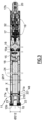
- the motorized drive device 5 comprises an electromechanical actuator 11, as illustrated in Fig. Figure 3 .
- the screen 2 of the concealment device 3 is wound on the winding tube 4 driven by the motorized drive device 5.
- the screen 2 is movable between a rolled up position, in particular high, and an unrolled position , especially bass.
- the screen 2 of the concealment device 3 is a closing, concealment and/or sun protection screen, winding and unrolling around the winding tube 4, the internal diameter of which is significantly greater than the external diameter of the electromechanical actuator 11, so that the electromechanical actuator 11 can be inserted into the winding tube 4, during the assembly of the concealment device 3.
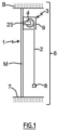
- the concealment device 3 comprises a holding device 9, 23.
- the holding device 9, 23 may comprise two supports 23.
- a support 23 is arranged at each end of the winding tube 4, in an assembled configuration of the concealment device 3.
- the winding tube 4 is held by means of the supports 23. Only one of the supports 23 is visible at the figure 1 .
- the supports 23 make it possible to mechanically connect the concealment device 3 to the structure of building B, in particular to a wall M of building B.
- the holding device 9, 23 may comprise a box 9.
- the winding tube 4 and at least part of the screen 2 are housed inside the box 9, in the assembled configuration of the device concealment 3.
- the box 9 is arranged above the opening 1, or even in the upper part of the opening 1.
- the supports 23 are also housed inside the box 9.
- the winding tube 4 is held via the box 9, in particular via the cheeks 10 of the box 9, without using supports, such as the supports 23 mentioned above.
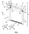
- the concealment device 3 can also comprise two lateral slides 26, as illustrated in figure 2 .
- Each side slide 26 comprises a groove 29.
- Each groove 29 of one of the side slides 26 cooperates, in other words is configured to cooperate, with a side edge 2a of the screen 2, in the assembled configuration of the concealment device 3 , so as to guide the screen 2, during the winding and unwinding of the screen 2 around the winding tube 4.
- the electromechanical actuator 11 is, for example, of the tubular type. This makes it possible to rotate the winding tube 4 around an axis of rotation X, so as to unwind or roll up the screen 2 of the concealment device 3.
- the screen 2 can be rolled up and unrolled on the winding tube 4.
- the electromechanical actuator 11 is inserted into the winding tube 4.
- the concealment device 3 also includes a load bar 8 to exert tension on the screen 2.
- the roll-up blind which forms the concealment device 3, comprises a canvas, forming the screen 2 of the roll-up blind 3.
- a first end of the screen 2, in particular the upper end of the screen 2, in the assembled configuration of the concealment device 3, is fixed to the winding tube 4.
- a second end of the screen 2, in particular the lower end of the screen 2, in the assembled configuration of the concealment device 3, is fixed to the load bar 8.
- the canvas forming the screen 2 is made from a textile material.
- the first end of the screen 2 has a hem through which a rod, in particular made of plastic material, is placed.
- This hem produced at the first end of the screen 2 is obtained by means of a seam of the canvas forming the screen 2.
- the hem and the rod located at the first end of the screen 2 are inserted by sliding into a groove provided on the external face of the winding tube 4, in particular over the entire length of the winding tube 4, of so as to secure the screen 2 with the winding tube 4 and to be able to wind and unwind the screen 2 around the winding tube 4.
- the rolled up position corresponds to a predetermined upper end position, or to the pressing of the load bar 8 of the screen 2 against an edge of a box 9 of the rollable blind 3
- the lower unrolled position corresponds to a predetermined lower end position, or to the pressing of the load bar 8 of the screen 2 against a threshold 7 of the opening 1, or else to the complete progress of screen 2.
- the motorized drive device 5 is controlled by a control unit.
- the control unit can be, for example, a local control unit 12 or a central control unit 13.
- the local control unit 12 can be connected, in a wired or non-wired connection, with the central control unit 13.
- the central control unit 13 can control the local control unit 12, as well as other similar local control units distributed throughout the building.
- the motorized drive device 5 is preferably configured to execute the commands for unwinding or winding the screen 2 of the concealment device 3, which can be issued, in particular, by the local control unit 12 or the central control unit 13.
- the installation 6 comprises either the local control unit 12, or the central control unit 13, or the local control unit 12 and the central control unit 13.
- the electromechanical actuator 11 comprises an electric motor 16.
- the electric motor 16 comprises a rotor and a stator, not shown, positioned coaxially around the axis of rotation motorized drive 5.
- Means for controlling the electromechanical actuator 11, allowing the movement of the screen 2 of the concealment device 3, comprise at least one electronic control unit 15.
- This electronic control unit 15 is capable of putting the motor into operation electrical 16 of the electromechanical actuator 11, and, in particular, allow the supply of electrical energy to the electric motor 16.
- the electronic control unit 15 controls, in particular, the electric motor 16, so as to open or close the screen 2, as described previously.
- the means for controlling the electromechanical actuator 11 comprise hardware and/or software means.
- the hardware means may include at least one microcontroller, not shown.
- the electronic control unit 15 also comprises a first communication module 27, as illustrated in figure 2 , in particular for receiving control orders, the control orders being issued by an order transmitter, such as the local control unit 12 or the central control unit 13, these orders being intended to control the device motorized drive 5.
- a first communication module 27 as illustrated in figure 2 , in particular for receiving control orders, the control orders being issued by an order transmitter, such as the local control unit 12 or the central control unit 13, these orders being intended to control the device motorized drive 5.
- the first communication module 27 of the electronic control unit 15 is of the wireless type.
- the first communication module 27 is configured to receive radio control orders.
- the first communication module 27 can also allow the reception of control orders transmitted by wired means.
- the electronic control unit 15, the local control unit 12 and/or the central control unit 13 can be in communication with a meteorological station located inside the building B or remote outside the building.
- building B including, in particular, one or more sensors that can be configured to determine, for example, a temperature, a brightness, or even a wind speed, in the case where the meteorological station is remote outside of building B.
- the electronic control unit 15, the local control unit 12 and/or the central control unit 13 can also be in communication with a server 28, as illustrated in Fig. figure 2 , so as to control the electromechanical actuator 11 according to data made available remotely by via a communications network, in particular an internet network that can be connected to the server 28.
- a communications network in particular an internet network that can be connected to the server 28.
- the electronic control unit 15 can be controlled from the local 12 or central 13 control unit.
- the local 12 or central 13 control unit is provided with a control keyboard.
- the control keyboard of the local or central control unit 12 or central 13 comprises one or more selection elements 14 and, optionally, one or more display elements 34.
- the selection elements may include push buttons and/or sensitive keys.
- the display elements may include light-emitting diodes and/or an LCD display (acronym for the Anglo-Saxon term “Liquid Crystal Display”) or TFT (acronym for the Anglo-Saxon term “Thin Film Transistor”).
- the selection and display elements can also be carried out using a touch screen.
- the local or central control unit 12 comprises at least one second communication module 36.
- the second communication module 36 of the local or central control unit 12 or central 13 is configured to emit, in other words emits, control orders, in particular by wireless means, for example radio, or by wired means .
- the second communication module 36 of the local or central control unit 12 or central 13 can also be configured to receive, in other words receive, control orders, in particular via the same means.
- the second communication module 36 of the local control unit 12 or central control unit 13 is configured to communicate, in other words communicate, with the first communication module 27 of the electronic control unit 15.
- the second communication module 36 of the local or central control unit 12 or central 13 exchanges control orders with the first communication module 27 of the electronic control unit 15, either monodirectionally or bidirectionally.
- the local control unit 12 is a control point, which can be fixed or nomadic.
- a fixed control point can be a control box intended to be fixed on a facade of a wall of building B or on a face of a frame of a window or a door.
- a portable control point can be a remote control, a smartphone or a tablet.
- the local control unit 12 or central 13 also includes a controller 35.
- the motorized drive device 5, in particular the electronic control unit 15, is preferably configured to execute movement control orders, in particular closing as well as opening, of the screen 2 of the device. concealment 3. These control orders can be issued, in particular, by the local control unit 12 or by the central control unit 13.
- the motorized drive device 5 can be controlled by the user, for example by receiving a control order corresponding to pressing one or more of the selection elements 14 of the local control unit 12 or central 13.
- the motorized drive device 5 can also be controlled automatically, for example by receiving a control order corresponding to at least one signal coming from at least one sensor and/or to a signal coming from a clock of the electronic control unit 15, in particular of the microcontroller.
- the sensor and/or the clock can be integrated into the local control unit 12 or the central control unit 13.
- the electromechanical actuator 11 comprises a casing 17, in particular tubular.
- the electric motor 16 is mounted inside the casing 17, in an assembled configuration of the electromechanical actuator 11, in particular according to a first and a second mounting configuration of a torque support 21 relative to the casing 17.
- the casing 17 of the electromechanical actuator 11 is of cylindrical shape, in particular of revolution.
- the casing 17 is made of a metallic material.
- the material of the electromechanical actuator housing is not restrictive and may be different. It may be, in particular, a plastic material.
- the electromechanical actuator 11 comprises at least one battery 24.
- the battery 24 is arranged inside the casing 17, in the assembled configuration of the electromechanical actuator 11, in particular according to the first mounting configuration of the torque support 21 relative to the casing 17.
- the electromechanical actuator 11 is supplied with electrical energy by means of the battery 24.
- the electromechanical actuator 11 comprises an electrical power cable 18 allowing the supply of electrical energy to the electronic control unit 15 and the electric motor 16, in particular from the battery 24.
- the battery 24 is of the rechargeable type.
- the battery 24 comprises one or more energy storage elements, not shown.
- the energy storage elements of the battery 24 can be, in particular, rechargeable accumulators or even rechargeable batteries.
- the motorized drive device 5 and, in particular, the electronic control unit 15, comprises charging elements configured to charge the battery 24 from the electrical energy supplied by an external electrical power source 25 , as illustrated in figure 2 .
- the external electrical power source 25 is a charger that can be plugged into a wall electrical outlet, so as to recharge the battery 24 from a mains power supply network.
- the external electrical power source 25 is an auxiliary battery, so as to recharge the battery 24.
- the battery 24 can be recharged by means of the auxiliary battery forming the external electrical power source 25, in particular in the case where the concealment device 3 is far from a wall electrical outlet.
- the electronic control unit 15 comprises a first electronic card 15a and a second electronic card 15b.
- the first electronic card 15a is configured to control the electric motor 16.
- the second electronic card 15b is configured to, in particular, allow the recharging of the battery 24, by means of an electrical connector, not shown, and , optionally, access settings and/or configuration functions of the electromechanical actuator 11, by means of selection and, possibly, display elements, not shown.
- the loading elements are arranged at the level of the second electronic card 15b.
- the electromechanical actuator 11 also comprises a reduction gear 19 and an output shaft 20.
- the reducer 19 comprises at least one reduction stage.
- the reduction stage can be an epicyclic type gear train.
- the type and number of reduction stages of the gearbox are not limiting.
- the electromechanical actuator 11 also includes a brake 32.
- the brake 32 can be a spring brake, a cam brake or an electromagnetic brake.
- the reducer 19 and, optionally, the brake 32 are arranged inside the casing 17 of the electromechanical actuator 11, in the assembled configuration of the electromechanical actuator 11, in particular according to the first and second mounting configurations of the torque support 21 relative to the casing 17.
- the electromechanical actuator 11 may also include an end of stroke and/or obstacle detection device, which may be mechanical or electronic.
- the winding tube 4 is rotated around the axis of rotation
- the first pivot connection is made at a first end of the winding tube 4 by means of a crown, not shown, inserted around a first end 17a of the casing 17 of the electromechanical actuator 11.
- the crown allows thus to achieve a level.
- the second pivot connection, not shown, is made at a second end of the winding tube 4.
- the electromechanical actuator 11 includes the torque support 21, which can also be called “actuator head”.
- the torque support 21 is arranged at the first end 17a of the casing 17 of the electromechanical actuator 11, in the assembled configuration of the electromechanical actuator 11, in particular according to the first and second mounting configurations of the torque support 21 relative to casing 17.
- the torque support 21 makes it possible to take up the forces exerted by the electromechanical actuator 11 and, in particular, to ensure the resumption of the forces exerted by the electromechanical actuator 11, in particular the torque exerted by the electromechanical actuator 11, by the structure of the building B.
- the torque support 21 advantageously makes it possible to take up, in addition, the forces exerted by the winding tube 4, in particular the weight of the winding tube 4, of the electromechanical actuator 11 and of the screen 2, and to ensure the recovery of these efforts by the structure of building B.
- the torque support 21 of the electromechanical actuator 11 makes it possible to fix the electromechanical actuator 11 on the holding device 9, 23, in particular to one of the supports 23 or to one of the cheeks 10 of the box 9 .
- the torque support 21 projects at the level of the first end 17a of the casing 17 of the electromechanical actuator 11, in particular the end 17a of the casing 17 receiving the crown.
- the crown constitutes, in other words is configured to constitute, a bearing for guiding the rotation of the winding tube 4, in the assembled configuration of the concealment device 3.
- the torque support 21 of the electromechanical actuator 11 can also make it possible to close the first end 17a of the casing 17.
- the torque support 21 of the electromechanical actuator 11 can make it possible to support at least part of the electronic control unit 15.
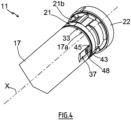
- the torque support 21 comprises a first part 21a and a second part 21b.
- the first part 21a of the torque support 21 is configured to cooperate, in other words cooperates, with the casing 17 of the electromechanical actuator 11, in particular in the assembled configuration of the electromechanical actuator 11 and, more particularly, according to the first and second mounting configurations of the torque support 21 relative to the casing 17.
- the second part 21b of the torque support 21 is configured to cooperate, in other words cooperates, with the holding device 9, 23, in particular in the assembled configuration of the electromechanical actuator 11 in the installation 6 and, more particularly, according to the first mounting configuration of the torque support 21 relative to the casing 17.
- the torque support 21 comprising the first and second parts 21a, 21b in a single piece makes it possible to improve the rigidity of the torque support 21.
- At least a portion of the first part 21a of the torque support 21 is of generally cylindrical shape and is arranged inside the casing 17 of the electromechanical actuator 11, in the assembled configuration of the electromechanical actuator 11, in particular according to the first and second mounting configurations of the torque support 21 relative to the casing 17.
- an outer diameter ⁇ 212 of at least a portion of the second part 21b of the torque support 21 is greater than an outer diameter ⁇ 17 of the casing 17 of the electromechanical actuator 11.
- the torque support 21 comprises a stop 33 configured to cooperate, in other words which cooperates, with the casing 17, at the first end 17a of the casing 17, in the assembled configuration of the electromechanical actuator 11, in particular according to the first mounting configuration of the torque support 21 relative to the casing 17.
- the stop 33 of the torque support 21 makes it possible to limit the penetration of the first part 21a of the torque support 21 into the casing 17, in the direction of the axis of rotation X.
- the stop 33 of the torque support 21 delimits the first and second parts 21 a, 21b of the torque support 21 relative to each other.
- the first part 21a of the torque support 21 is arranged inside the casing 17 of the electromechanical actuator 11, following the fitting of the torque support 21 inside the casing 17, up to the stop 33, in the assembled configuration of the electromechanical actuator 11, in particular according to the first mounting configuration of the torque support 21 relative to the casing 17.
- the stop 33 of the torque support 21 is made in the form of a shoulder and, more particularly, in the form of a collar, in particular of cylindrical shape and with a rectilinear generator.
- the electronic control unit 15 can be supplied with electrical energy by means of the electrical power cable 18.
- the electronic control unit 15 can be arranged at least partly inside the casing 17 of the electromechanical actuator 11.
- the electronic control unit 15 can be arranged at least partly outside the casing 17 of the electromechanical actuator 11 and, in particular, mounted on one of the two supports 23, on one of the cheeks 10 of the box 9 or in the torque support 21.
- the first electronic card 15a of the electronic control unit 15 is arranged inside the casing 17 of the electromechanical actuator 11.
- the second electronic card 15b is arranged inside the torque support 21 of the electromechanical actuator 11.
- the torque support 21 comprises a cover 22.
- the second electronic card 15b is arranged inside a housing formed between the second part 21b of the torque support 21 and the cover 22.
- the torque support 21 comprises at least one button, not shown.
- buttons can make it possible to adjust the electromechanical actuator 11 through one or more configuration modes, to pair one or more control units 12, 13 with the electromechanical actuator 11, to reset one or more several parameters, which can be, for example, an end position, to reset the paired control unit(s) 12, 13 or even to control the movement of the screen 2.
- the torque support 21 includes a single button.
- the number of torque support buttons is not limiting and may be different. It may, in particular, be greater than or equal to two.
- the torque support 21 comprises at least one display device, not shown, so as to allow a visual indication, which may be, for example, a state of charge of the battery 24.
- the display device comprises at least one lighting source, not shown, in particular a light-emitting diode, mounted on the second electronic card 15b and, optionally, a transparent or translucent cover and/or a light guide, for allow the passage of light emitted by the source lighting.
- a lighting source not shown, in particular a light-emitting diode, mounted on the second electronic card 15b and, optionally, a transparent or translucent cover and/or a light guide, for allow the passage of light emitted by the source lighting.
- the torque support 21 comprises a single display device.
- the number of display devices is not limiting and may be different. It may, in particular, be greater than or equal to two.
- the output shaft 20 of the electromechanical actuator 11 is arranged inside the winding tube 4 and at least partly outside the casing 17 of the electromechanical actuator 11.
- one end of the output shaft 20 projects relative to the casing 17 of the electromechanical actuator 11, in particular relative to a second end 17b of the casing 17 opposite the first end 17a.
- the output shaft 20 of the electromechanical actuator 11 is configured to rotate a connecting element, not shown, connected to the winding tube 4.
- the connecting element is made in the form of a wheel .
- the electric motor 16 and the gearbox 19 rotate the output shaft 20.
- the output shaft 20 of the electromechanical actuator 11 rotates the winding tube 4 via the connecting element.
- the winding tube 4 rotates the screen 2 of the concealment device 3, so as to open or close the opening 1.
- the casing 17 comprises at least one mounting element 37.
- the or each mounting element 37 of the casing 17 can also be called “indexing element” of the casing 17.
- the or each mounting element 37 of the casing 17 is provided at the level of the first end 17a of the casing 17.
- the casing 17 includes two mounting elements 37.
- the two mounting elements 37 of the casing 17 are arranged at an angle of 180° relative to each other, around the axis of rotation X. In other words, the two mounting elements 37 of the casing 17 are diametrically opposed to the axis of rotation X.
- the number and angular position of the casing mounting elements are not limiting and may be different.
- the housing mounting elements may be one or more in number and, for example, three in number and arranged at an angle of 120° to each other, around the axis of rotation.
- each mounting element 37 of the casing 17 is produced by a recessed zone of the casing 17, in other words by a deformation of the external surface of the casing 17 in the direction of the axis of rotation X.
- the or each mounting element 37 of the casing 17 can also be called “third mounting element”.
- the torque support 21, in particular the first part 21a of the torque support 21, comprises at least one first mounting element 38 and at least one second mounting element 39.
- the or each first mounting element 38 of the torque support 21 can also be called “first indexing element” of the torque support 21.
- the or each second mounting element 39 of the torque support 21 can also be called “second indexing element” of the torque support 21.
- the torque support 21 comprises two first mounting elements 38 and two second mounting elements 39.
- the two first mounting elements 38 of the torque support 21 are arranged at an angle of 180° relative to each other. other, around the axis of rotation 21 are arranged at an angle of 180° relative to each other, around the axis of rotation axis of rotation
- the number and angular position of the first and second mounting elements of the torque support are not limiting and may be different and, more particularly, are dependent on the number of mounting elements of the housing.
- the first and second mounting elements of the torque support can be respectively one in number or strictly greater than two and, for example, three in number and arranged at an angle of 120° relative to each other , around the axis of rotation.
- each of the first and second mounting elements 38, 39 of the torque support 21 and the or each mounting element 37 of the casing 17 are press-fit mounting elements. Furthermore, each of the first and second mounting elements 38, 39 of the torque support 21 is configured to cooperate, in other words cooperates, with the or one of the mounting elements 37 of the casing 17 by cooperation of shapes.
- each first mounting element 38 of the torque support 21 is produced by a hollow zone of the torque support 21, in other words by a deformation in the direction of the axis of rotation X.
- each second mounting element 39 of torque support 21 is produced by a hollow zone of the torque support 21, in other words by a deformation in the direction of the axis of rotation X.
- first mounting elements 38 are identical to each other and the second mounting elements 39 are identical to each other.
- Each first mounting element 38 of the torque support 21 is configured to be mounted, in other words is mounted, with one of the mounting elements 37 of the casing 17, according to the first mounting configuration of the torque support 21 relative to the casing 17.
- the first mounting configuration corresponds to a functional assembly configuration of the electromechanical actuator 11.
- the functional assembly configuration of the electromechanical actuator 11 corresponds to a final assembly configuration of the electromechanical actuator 11 in which the electromechanical actuator 11 is capable of being put into service in the installation 6, in other words assembled and configured to rotate the winding tube 4 of the concealment device 3.
- the torque support 21 is oriented and locked in rotation around the axis of rotation mounting 37 of the casing 17.
- Each second mounting element 39 of the torque support 21 is different from a first mounting element 38 of the torque support 21.
- each second mounting element 39 has a shape different from that of a first mounting element 38.
- Each second mounting element 39 of the torque support 21 is configured to be mounted, in other words is mounted, with one of the mounting elements 37 of the casing 17, according to the second mounting configuration of the torque support 21 relative to the casing 17.
- the second mounting configuration corresponds to a control configuration of the electromechanical actuator 11.
- the torque support 21 is oriented and locked in rotation around the axis of rotation mounting 37 of the casing 17.
- the or each first mounting element 38 of the torque support 21 is different from the or each second mounting element 39 of the torque support 21, so that, according to the first mounting configuration of the torque support 21 relative to the casing 17, the or each first mounting element 38 of the torque support 21 is mounted, in other words is configured to be mounted, with the or one of the elements mounting 37 of the casing 17 to guarantee a functional assembly configuration of the electromechanical actuator 11 and that, according to the second mounting configuration of the torque support 21 relative to the casing 17, the or each second mounting element 39 of the support torque 21 is mounted, in other words is configured to be mounted, with the or one of the mounting elements 37 of the casing 17 to guarantee a control configuration of the electromechanical actuator 11.
- such an electromechanical actuator 11 makes it possible to guarantee mounting of the torque support 21 relative to the casing 17 in at least a first position, in a first functional assembly configuration of the electromechanical actuator 11, and in at least a second position, in a second additional assembly configuration of the electromechanical actuator 11 which is that of controlling the electromechanical actuator 11 and which is therefore different from the first functional assembly configuration of the electromechanical actuator 11.
- the torque support 21 can thus be mounted relative to the casing 17 in at least two distinct positions, in particular according to the first and second mounting configurations, of which a first mounting position of the torque support 21 relative to the casing 17 is a functional assembly position of the electromechanical actuator 11, where the torque support 21 is configured to be fixed to the casing 17, and a second mounting position of the torque support 21 relative to the casing 17 is a control position of the electromechanical actuator 11, where the control position is different from the functional assembly position of the electromechanical actuator 11.
- an electromechanical actuator 11 allows the mounting of the torque support 21 relative to the casing 17 according to the first and second mounting configurations on the same station of a manufacturing unit, so as to minimize assembly time of the electromechanical actuator 11 and to limit investments to obtain the manufacturing unit.
- the second mounting configuration corresponding to a control configuration of the electromechanical actuator 11, is intended to be used in the factory to carry out a control of the electromechanical actuator 11.
- the second mounting configuration corresponding to a control configuration of the electromechanical actuator 11, is intended to be used in the factory to measure the intensity of an electric current circulating in the electromechanical actuator 11, in particular when it is configured to be equipped with the battery 24.
- the intensity measurement of the electromechanical actuator 11 is implemented before assembling the battery 24 inside of the casing 17 and before the electrical connection of the battery 24 to the electronic control unit 15, in particular to the first electronic card 15a, by means of the electrical power cable 18.
- an intensity measurement of the electromechanical actuator 11 can be implemented in the absence of the battery 24 and when the torque support 21, in particular the first part 21a of the torque support 21, is partially inserted in the casing 17, in particular according to the second mounting configuration of the torque support 21 relative to the casing 17.
- measuring the intensity of the electromechanical actuator 11 makes it possible to check the compatibility of the battery 24 to be assembled in the electromechanical actuator 11 with the electronic control unit 15 and the electric motor 16, before assembly. of the battery 24 inside the casing 17 and before the electrical connection of the battery 24 to the electronic control unit 15, in particular to the first electronic card 15a, by means of the electrical power cable 18.
- the transition from the first mounting configuration to the second mounting configuration, and vice versa is implemented by a rotational movement R, around the axis of rotation X, of the torque support 21 relative to the casing 17 .
- the torque support 21 is configured to be oriented, in other words is oriented, relative to the casing 17, around the axis of rotation X of the electromechanical actuator 11 and in the first mounting configuration, with a first orientation of the support torque 21 relative to the casing 17.
- the torque support 21 is also configured to be oriented, in other words is oriented, relative to the casing 17, around the axis of rotation X and in the second mounting configuration, with a second orientation of the torque support 21 relative to the casing 17.
- the first and second orientations of the torque support 21 relative to the casing 17 are offset relative to each other, around the axis of rotation X, of a predetermined non-zero angular value ⁇ .
- the predetermined angular value ⁇ is included in a range of values extending between 20° and 160° and is preferably of the order of 90°.
- the first and second orientations of the torque support 21 relative to the casing 17 are determined by an angular positioning of the or each first mounting element 38 of the torque support 21 relative to the or each second mounting element 39 of the support of torque 21, around the axis of rotation X.
- the or each second mounting element 39 of the torque support 21 is configured to be housed, in other words is housed, inside the casing 17, according to the first mounting configuration.
- the or each second mounting element 39 of the torque support 21 is offset relative to the or one of the mounting elements 37 of the casing 17, around the axis of rotation X, so as not to interfere with the or one of the mounting elements 37 of the casing 17.
- the or each first mounting element 38 of the torque support 21 is configured to be housed, in other words is housed, inside the casing 17, according to the second mounting configuration.
- the or each first mounting element 38 of the torque support 21 is offset relative to the or one of the mounting elements 37 of the casing 17, around the axis of rotation X, so as not to interfere with the or one of the mounting elements 37 of the casing 17.
- the first mounting element 38 of the torque support 21 comprises a first stop 43.
- the second mounting element 39 of the torque support 21 comprises a second stop 44.
- the casing 17 comprises an edge 45 at the first end 17a of the casing 17.
- the edge 45 of the casing 17 is configured to be placed in support, in other words is placed in support, with the first stop 43 of the first mounting element 38 of the torque support 21, in the first mounting configuration, of so that the torque support 21, in particular the first part 21a of the torque support 21, is inserted partly inside the casing 17 at a first predetermined distance L1 parallel to the axis of rotation X of the electromechanical actuator 11.
- the edge 45 of the casing 17 is also configured to be placed in support, in other words is placed in support, with the second stop 44 of the second mounting element 39 of the torque support 21, in the second mounting configuration, so that the torque support 21, in particular the first part 21a of the torque support 21, is inserted partly inside the casing 17 at a second predetermined distance L2 parallel to the axis of rotation predetermined distance L1 is greater than the second predetermined distance L2.
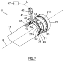
- each of the first and second predetermined distances L1, L2 for insertion of the torque support 21 inside the casing 17, along the axis of rotation X and in each of the first and second mounting configurations is defined by a length between the edge 45 of the casing 17, at the level of the first end 17a of the casing 17, and an edge 46 of the torque support 21, in particular of the first part 21a of the torque support 21, at the level of an end 21c torque support 21 configured to be inserted into the casing 17.
- the torque support 21 comprises at least one notch 40.
- the notch 40 of the torque support 21 is configured to be closed by the casing 17, in the first mounting configuration, and to be unobstructed relative to the casing 17, that is to say not being totally obstructed by it, in the second mounting configuration.
- the notch 40 is configured to allow the control of the electromechanical actuator 11, in particular the measurement of intensity of the latter, when the torque support 21 is mounted relative to the casing 17, according to the second mounting configuration .
- the notch 40 of the torque support 21 can also be called “opening", in particular through, or "notch".
- the notch 40 of the torque support 21 is formed in the or each second mounting element 39 of the torque support 21.
- the notch 40 of the torque support 21 is configured for the passage of at least one electrical power cable 41, from the inside of the casing 17 to the outside of the casing 17, in the second configuration of assembly.
- the electrical power cable 41 extends, on the one hand, inside the casing 17 and, on the other hand, outside the casing 17 and crosses the notch 40 of the torque support 21.
- the electronic control unit 15, in particular the first electronic card 15a is configured to be electrically connected to a control tool 47 by an electrical connection L, in the second mounting configuration.
- the electrical connection L between the electronic control unit 15, in particular the first electronic card 15a, and the control tool 47 is implemented by the electrical supply cable 41 extending through the notch 40 made in the torque support 21.
- the electrical supply cable 41 is configured to be electrically connected, in other words is electrically connected, to the electronic control unit 15, in particular to the first electronic card 15a of the electronic control unit 15, in the first and second mounting configurations.
- the electrical power cable 41 comprises an electrical connector 42.
- the electrical connector 42 of the electrical power cable 41 is configured to cooperate with an electrical connector, not shown, of the control tool 47.
- the battery 24 is inserted inside the casing 17 then the torque support 21 is assembled with the casing 17 according to the first mounting configuration.
- the battery 24 includes an electrical connector, not shown. Furthermore, the electrical connector of the battery 24 is configured to be electrically connected, in other words is electrically connected, to the electrical connector 42 of the electrical power cable 41, prior to the insertion of the battery 24 inside the casing 17.
- the electrical connector 42 of the electrical power cable 41 makes it possible, on the one hand, to supply electrical energy to the electronic control unit 15, in particular the first electronic card 15a, and the electric motor 16, according to the first mounting configuration, and, on the other hand, to implement the control of the electromechanical actuator 11, according to the second mounting configuration.
- the casing 17 and the torque support 21 are configured to be fixed together, in other words are fixed together, by means of at least one fixing element 48, only according to the first mounting configuration.
- the fixing of the casing 17 with the torque support 21 makes it possible to block the torque support 21 in translation relative to the casing 17.
- the fixing of the casing 17 with the torque support 21 is implemented according to the first mounting configuration and not according to the second mounting configuration.
- the second mounting configuration is a temporary assembly configuration of the torque support 21 with the casing 17.
- the fixing of the casing 17 and the torque support 21, according to the first mounting configuration is implemented following the insertion of the battery 24 inside the casing 17.
- the fixing element(s) 48 of the casing 17 with the torque support 21 are screw fixing elements, in particular fixing screws which can be, for example, self-tapping.
- housing fixing elements with the torque support is not limiting and may be different. These may be, for example, fastening elements by riveting or by elastic snap-fastening.
- the casing 17 comprises at least one through hole 49 of a fixing element 48.
- the torque support 21 comprises at least one through hole 49. fixing 50 of a fixing element 48.
- the electromechanical actuator 11 comprises two fixing elements 48.
- the casing 17 comprises two through holes 49.
- the torque support 21 comprises two fixing holes 50. The number of through holes 49 of the casing 17 and of fixing holes 50 of the torque support 21 is dependent on the number of fixing elements 48.
- the number of fixing elements, housing passage holes and torque support fixing holes is not limiting and may be different. It can be, for example, one or strictly greater than two.
- each fixing screw 48 passes through one of the through holes 49 of the casing 17 and is screwed into one of the fixing holes 50 of the torque support 21.
- At least one through hole 49 of the casing 17 is provided in a mounting element 37 of the casing 17.
- at least one fixing hole 50 of the torque support 21 is provided in a first mounting element 38 of the support of torque 21.
- the number of through holes 49 of the casing 17 and of fixing holes 50 of the torque support 21 is dependent on the number of first mounting elements 38 of the torque support 21, and vice versa.
- each through hole 49 of the casing 17 is provided in one of the mounting elements 37 of the casing 17.
- each fixing hole 50 of the torque support 21 is provided in one of the first mounting elements 38 of the torque support 21.
- the first torque bracket mounting member is different from the second torque bracket mounting member, such that the first torque bracket mounting member is mounted with the crankcase mounting member for ensure a functional assembly configuration of the electromechanical actuator, in the first mounting configuration of the torque bracket relative to the housing, and that the second mounting element of the torque bracket is mounted with the mounting element of the housing to guarantee a control configuration of the electromechanical actuator, in the second mounting configuration of the torque support relative to the housing.
- such an electromechanical actuator makes it possible to guarantee mounting of the torque support relative to the casing in at least a first position, in a first functional assembly configuration of the electromechanical actuator, and in at least a second position, in a second assembly configuration of the additional electromechanical actuator which is that of controlling the electromechanical actuator and which is therefore different from the first functional assembly configuration of the electromechanical actuator.
- the electromechanical actuator 11 is inserted in a rail, in particular of square or rectangular section, which can be opened at one or both ends, in the assembled configuration of the concealment device 3.
- the electromechanical actuator 11 can be configured to drive a drive shaft on which cords for moving and/or orienting the screen 2 are wound.
- the electromechanical actuator 11 is supplied with electrical energy by a sector electrical energy supply network.
Landscapes
- Engineering & Computer Science (AREA)
- Structural Engineering (AREA)
- Architecture (AREA)
- Civil Engineering (AREA)
- Operating, Guiding And Securing Of Roll- Type Closing Members (AREA)
- Connection Of Motors, Electrical Generators, Mechanical Devices, And The Like (AREA)
- Power-Operated Mechanisms For Wings (AREA)
Description
La présente invention concerne un actionneur électromécanique comprenant un support de couple, destiné à être monté au moins en partie à l'intérieur d'un carter de l'actionneur électromécanique, ainsi qu'une installation de fermeture, d'occultation ou de protection solaire comprenant un écran enroulable sur un tube d'enroulement entraîné en rotation par un tel actionneur électromécanique.The present invention relates to an electromechanical actuator comprising a torque support, intended to be mounted at least partly inside a casing of the electromechanical actuator, as well as a closing, concealment or solar protection installation. comprising a roll-up screen on a winding tube rotated by such an electromechanical actuator.
De manière générale, la présente invention concerne le domaine des dispositifs d'occultation comprenant un dispositif d'entraînement motorisé mettant en mouvement un écran, entre au moins une première position et au moins une deuxième position.Generally speaking, the present invention relates to the field of concealment devices comprising a motorized drive device setting in motion a screen, between at least a first position and at least a second position.
Un dispositif d'entraînement motorisé comprend un actionneur électromécanique d'un élément mobile de fermeture, d'occultation ou de protection solaire, tel qu'un volet, une porte, une grille, un store ou tout autre matériel équivalent, appelé par la suite écran.A motorized drive device comprises an electromechanical actuator of a mobile closing, concealment or solar protection element, such as a shutter, a door, a grille, a blind or any other equivalent material, called hereinafter screen.
On connaît déjà des actionneurs électromécaniques, tel que par exemple dans le document
Cependant, ces actionneurs électromécaniques présentent l'inconvénient que les deux éléments de montage du support de couple sont identiques et que les deux éléments de montage du carter sont identiques.However, these electromechanical actuators have the disadvantage that the two mounting elements of the torque support are identical and the two mounting elements of the housing are identical.
De cette manière, les éléments de montage du support de couple et du carter permettent uniquement un montage du support de couple par rapport au carter selon une première position ou selon une deuxième position, avec une orientation de 180° l'une par rapport à l'autre, dans une configuration d'assemblage fonctionnel de l'actionneur électromécanique.In this way, the mounting elements of the torque bracket and the housing only allow mounting of the torque support relative to the casing in a first position or in a second position, with an orientation of 180° relative to each other, in a functional assembly configuration of the electromechanical actuator .
La configuration d'assemblage fonctionnel de l'actionneur électromécanique correspond à une configuration d'assemblage final de l'actionneur électromécanique dans laquelle l'actionneur électromécanique est apte à être mis en service dans l'installation de fermeture, d'occultation ou de protection solaire.The functional assembly configuration of the electromechanical actuator corresponds to a final assembly configuration of the electromechanical actuator in which the electromechanical actuator is capable of being put into service in the closing, concealment or protection installation solar.
Les première et deuxième positions de montage du support de couple par rapport au carter permettent une facilité d'industrialisation de l'actionneur électromécanique, puisque le support de couple et le carter sont respectivement symétriques autour de l'axe de rotation.The first and second mounting positions of the torque support relative to the casing allow ease of industrialization of the electromechanical actuator, since the torque support and the casing are respectively symmetrical around the axis of rotation.
Par conséquent, l'assemblage du support de couple par rapport au carter présente deux positions de montage seulement pour garantir un assemblage fonctionnel de l'actionneur électromécanique.Therefore, the assembly of the torque bracket relative to the housing has only two mounting positions to ensure functional assembly of the electromechanical actuator.
La présente invention a pour but de résoudre les inconvénients précités et de proposer un actionneur électromécanique pour une installation de fermeture, d'occultation ou de protection solaire, ainsi qu'une installation de fermeture, d'occultation ou de protection solaire comprenant un tel actionneur électromécanique, permettant de garantir un montage d'un support de couple de l'actionneur électromécanique par rapport à un carter de l'actionneur électromécanique selon au moins une première position, dans une première configuration d'assemblage fonctionnel de l'actionneur électromécanique, et selon au moins une deuxième position, dans une deuxième configuration d'assemblage de l'actionneur électromécanique additionnelle, différente de la première configuration d'assemblage fonctionnel de l'actionneur électromécanique.The present invention aims to resolve the aforementioned drawbacks and to propose an electromechanical actuator for a closing, concealment or solar protection installation, as well as a closure, concealment or solar protection installation comprising such an actuator. electromechanical, making it possible to guarantee mounting of a torque support of the electromechanical actuator relative to a casing of the electromechanical actuator in at least a first position, in a first functional assembly configuration of the electromechanical actuator, and according to at least a second position, in a second assembly configuration of the additional electromechanical actuator, different from the first functional assembly configuration of the electromechanical actuator.
A cet égard, la présente invention vise, selon un premier aspect, un actionneur électromécanique pour une installation de fermeture, d'occultation ou de protection solaire,
l'actionneur électromécanique comprenant au moins :
- un moteur électrique,
- un carter, le moteur électrique étant monté à l'intérieur du carter dans une configuration assemblée de l'actionneur électromécanique, le carter comprenant au moins un élément de montage, et
- un support de couple, le support de couple étant disposé au niveau d'une première extrémité du carter dans la configuration assemblée de l'actionneur électromécanique, le support de couple comprenant au moins un premier élément de montage.
the electromechanical actuator comprising at least:
- an electric motor,
- a housing, the electric motor being mounted inside the housing in an assembled configuration of the electromechanical actuator, the housing comprising at least one mounting element, and
- a torque support, the torque support being disposed at a first end of the housing in the assembled configuration of the electromechanical actuator, the torque support comprising at least a first mounting element.
Le premier élément de montage du support de couple est configuré pour être monté avec l'élément de montage du carter, selon une première configuration de montage du support de couple par rapport au carter, la première configuration de montage correspondant à une configuration d'assemblage fonctionnel de l'actionneur électromécanique.The first torque support mounting member is configured to be mounted with the housing mounting member, according to a first mounting configuration of the torque support relative to the housing, the first mounting configuration corresponding to an assembly configuration functional of the electromechanical actuator.
Selon l'invention, le support de couple comprend, en outre, au moins un deuxième élément de montage. Le deuxième élément de montage du support de couple est différent du premier élément de montage du support de couple. Le deuxième élément de montage du support de couple est configuré pour être monté avec l'élément de montage du carter, selon une deuxième configuration de montage du support de couple par rapport au carter, la deuxième configuration de montage correspondant à une configuration de contrôle de l'actionneur électromécanique. Le support de couple est configuré pour être orienté par rapport au carter, autour d'un axe de rotation de l'actionneur électromécanique et dans la première configuration de montage, avec une première orientation du support de couple par rapport au carter. Le support de couple est également configuré pour être orienté par rapport au carter, autour de l'axe de rotation et dans la deuxième configuration de montage, avec une deuxième orientation du support de couple par rapport au carter. En outre, les première et deuxième orientations du support de couple par rapport au carter sont décalées l'une par rapport à l'autre, autour de l'axe de rotation, d'une valeur angulaire prédéterminée non nulle.According to the invention, the torque support further comprises at least one second mounting element. The second torque bracket mounting member is different from the first torque bracket mounting member. The second torque support mounting element is configured to be mounted with the housing mounting element, according to a second mounting configuration of the torque support relative to the housing, the second mounting configuration corresponding to a control configuration of the electromechanical actuator. The torque support is configured to be oriented relative to the housing, around an axis of rotation of the electromechanical actuator and in the first mounting configuration, with a first orientation of the torque support relative to the housing. The torque bracket is also configured to be oriented relative to the housing, about the axis of rotation and in the second mounting configuration, with a second orientation of the torque bracket relative to the housing. In addition, the first and second orientations of the torque support relative to the casing are offset relative to each other, around the axis of rotation, by a predetermined non-zero angular value.
Ainsi, le premier élément de montage du support de couple est différent du deuxième élément de montage du support de couple, de sorte que, selon la première configuration de montage du support de couple par rapport au carter, le premier élément de montage du support de couple est monté avec l'élément de montage du carter pour garantir une configuration d'assemblage fonctionnel de l'actionneur électromécanique et que, selon la deuxième configuration de montage du support de couple par rapport au carter, le deuxième élément de montage du support de couple est monté avec l'élément de montage du carter pour garantir une configuration de contrôle de l'actionneur électromécanique.Thus, the first mounting element of the torque support is different from the second mounting element of the torque support, so that, according to the first mounting configuration of the torque support relative to the casing, the first mounting element of the torque support torque is mounted with the housing mounting element to ensure a functional assembly configuration of the electromechanical actuator and that, according to the second mounting configuration of the torque support relative to the housing, the second mounting element of the torque support Torque is mounted with the housing mounting element to ensure a control configuration of the electromechanical actuator.
De cette manière, un tel actionneur électromécanique permet de garantir un montage du support de couple par rapport au carter selon au moins une première position, dans une première configuration d'assemblage fonctionnel de l'actionneur électromécanique, et selon au moins une deuxième position, dans une deuxième configuration d'assemblage de l'actionneur électromécanique additionnelle qui est celle du contrôle de l'actionneur électromécanique et qui est donc différente de la première configuration d'assemblage fonctionnel de l'actionneur électromécanique.In this way, such an electromechanical actuator makes it possible to guarantee mounting of the torque support relative to the casing in at least a first position, in a first functional assembly configuration of the electromechanical actuator, and in at least a second position, in a second assembly configuration of the additional electromechanical actuator which is that of controlling the electromechanical actuator and which is therefore different from the first functional assembly configuration of the electromechanical actuator.
Selon une caractéristique avantageuse de l'invention, le support de couple comprend au moins une encoche. En outre, l'encoche du support de couple est configurée pour être obturée par le carter, dans la première configuration de montage, et pour être désobstruée par rapport au carter, dans la deuxième configuration de montage.According to an advantageous characteristic of the invention, the torque support comprises at least one notch. In addition, the notch of the torque support is configured to be closed by the casing, in the first mounting configuration, and to be unobstructed relative to the casing, in the second mounting configuration.
Selon une autre caractéristique avantageuse de l'invention, l'encoche du support de couple est ménagée dans le ou chaque deuxième élément de montage du support de couple.According to another advantageous characteristic of the invention, the notch of the torque support is formed in the or each second mounting element of the torque support.
Selon une autre caractéristique avantageuse de l'invention, l'encoche du support de couple est configurée pour le passage d'au moins un câble d'alimentation électrique, à partir de l'intérieur du carter vers l'extérieur du carter, dans la deuxième configuration de montage.According to another advantageous characteristic of the invention, the notch of the torque support is configured for the passage of at least one electrical power cable, from the inside of the casing to the outside of the casing, in the second mounting configuration.
Selon une autre caractéristique avantageuse de l'invention, les première et deuxième orientations du support de couple par rapport au carter sont déterminées par un positionnement angulaire du premier élément de montage du support de couple par rapport au deuxième élément de montage du support de couple, autour de l'axe de rotation.According to another advantageous characteristic of the invention, the first and second orientations of the torque support relative to the casing are determined by an angular positioning of the first mounting element of the torque support relative to the second mounting element of the torque support, around the axis of rotation.
Selon une autre caractéristique avantageuse de l'invention, chacun des premier et deuxième éléments de montage du support de couple et l'élément de montage du carter sont des éléments de montage par emmanchement. En outre, chacun des premier et deuxième éléments de montage du support de couple est configuré pour coopérer avec l'élément de montage du carter par coopération de formes.According to another advantageous characteristic of the invention, each of the first and second mounting elements of the torque support and the mounting element of the casing are press-fit mounting elements. Furthermore, each of the first and second mounting elements of the torque support is configured to cooperate with the mounting element of the housing by cooperation of shapes.
Selon une autre caractéristique avantageuse de l'invention, le premier élément de montage du support de couple comprend une première butée. Le deuxième élément de montage du support de couple comprend une deuxième butée. Le carter comprend un bord au niveau de la première extrémité du carter. Le bord du carter est configuré pour être mis en appui avec la première butée du premier élément de montage du support de couple, dans la première configuration de montage, de sorte que le support de couple est inséré en partie à l'intérieur du carter selon une première distance prédéterminée parallèle à un axe de rotation de l'actionneur électromécanique. Le bord du carter est également configuré pour être mis en appui avec la deuxième butée du deuxième élément de montage du support de couple, dans la deuxième configuration de montage, de sorte que le support de couple est inséré en partie à l'intérieur du carter selon une deuxième distance prédéterminée parallèle à l'axe de rotation. En outre, la première distance prédéterminée est supérieure à la deuxième distance prédéterminée.According to another advantageous characteristic of the invention, the first mounting element of the torque support comprises a first stop. The second torque bracket mounting member includes a second stop. The housing includes an edge at the first end of the housing. The edge of the housing is configured to abut with the first stop of the first mounting element of the torque support, in the first mounting configuration, so that the torque support is inserted partly inside the housing according to a first predetermined distance parallel to an axis of rotation of the electromechanical actuator. The edge of the housing is also configured to abut with the second stop of the second mounting member of the torque bracket, in the second mounting configuration, such that the torque bracket is inserted partially inside the housing according to a second predetermined distance parallel to the axis of rotation. Furthermore, the first predetermined distance is greater than the second predetermined distance.
Selon une autre caractéristique avantageuse de l'invention, l'actionneur électromécanique comprend au moins une batterie, la batterie étant disposée à l'intérieur du carter, dans la configuration assemblée de l'actionneur électromécanique.According to another advantageous characteristic of the invention, the actuator electromechanical includes at least one battery, the battery being disposed inside the housing, in the assembled configuration of the electromechanical actuator.
Selon une autre caractéristique avantageuse de l'invention, l'actionneur électromécanique comprend une unité électronique de contrôle. En outre, l'unité électronique de contrôle est configurée pour être reliée électriquement à un outil de contrôle par une liaison électrique, dans la deuxième configuration de montage.According to another advantageous characteristic of the invention, the electromechanical actuator comprises an electronic control unit. Furthermore, the electronic control unit is configured to be electrically connected to a control tool by an electrical connection, in the second mounting configuration.
Selon une autre caractéristique avantageuse de l'invention, dans la deuxième configuration de montage, la liaison électrique entre l'unité électronique de contrôle et l'outil de contrôle est mise en oeuvre par le câble d'alimentation d'électrique s'étendant au travers de l'encoche ménagée dans le support de couple.According to another advantageous characteristic of the invention, in the second mounting configuration, the electrical connection between the electronic control unit and the control tool is implemented by the electrical power cable extending to the through the notch in the torque support.
La présente invention vise, selon un deuxième aspect, une installation de fermeture, d'occultation ou de protection solaire comprenant un écran, un tube d'enroulement et un actionneur électromécanique, selon l'invention et tel que mentionné ci-dessus, l'écran étant enroulable sur le tube d'enroulement et le tube d'enroulement étant agencé de sorte à être entraîné en rotation par l'actionneur électromécanique.The present invention aims, according to a second aspect, at a closing, concealment or solar protection installation comprising a screen, a winding tube and an electromechanical actuator, according to the invention and as mentioned above, the screen being rollable on the winding tube and the winding tube being arranged so as to be rotated by the electromechanical actuator.
Cette installation présente des caractéristiques et avantages analogues à ceux décrits précédemment, en relation avec l'actionneur électromécanique selon l'invention.This installation has characteristics and advantages similar to those described above, in relation to the electromechanical actuator according to the invention.
D'autres particularités et avantages de l'invention apparaîtront encore dans la description ci-après, faite en référence aux dessins annexés, donnés à titre d'exemples non limitatifs :
- [
Fig 1 ] lafigure 1 est une vue schématique en coupe transversale d'une installation conforme à un mode de réalisation de l'invention ; - [
Fig 2 ] lafigure 2 est une vue schématique en perspective de l'installation illustrée à lafigure 1 ; - [
Fig 3 ] lafigure 3 est une vue en coupe schématique d'un actionneur électromécanique de l'installation illustrée auxfigures 1 et2 , selon un plan de coupe passant par un axe de rotation d'un arbre de sortie de l'actionneur électromécanique ; - [
Fig 4 ] lafigure 4 est une vue schématique en perspective d'une partie de l'actionneur électromécanique illustré à lafigure 3 , représentant une partie du carter de l'actionneur électromécanique et un support de couple, dans une première configuration de montage ; - [
Fig 5 ] lafigure 5 est une vue schématique éclatée et en perspective de la partie de l'actionneur électromécanique illustrée à lafigure 4 , selon la première configuration de montage ; - [
Fig 6 ] lafigure 6 est une vue schématique de côté de la partie de l'actionneur électromécanique illustrée auxfigures 4 et5 , selon la première configuration de montage ; - [
Fig 7 ] lafigure 7 est une vue schématique en perspective d'une partie de l'actionneur électromécanique illustré à lafigure 3 , représentant une partie du carter de l'actionneur électromécanique et le support de couple, dans une deuxième configuration de montage ; - [
Fig 8 ] lafigure 8 est une vue schématique éclatée et en perspective de la partie de l'actionneur électromécanique illustrée à lafigure 7 , selon la deuxième configuration de montage ; et - [
Fig 9 ] lafigure 9 est une vue schématique de côté de la partie de l'actionneur électromécanique illustrée auxfigures 7 et8 , selon la deuxième configuration de montage.
- [
Figure 1 ] therefigure 1 is a schematic cross-sectional view of an installation according to one embodiment of the invention; - [
Figure 2 ] therefigure 2 is a schematic perspective view of the installation illustrated infigure 1 ; - [
Figure 3 ] thereFigure 3 is a schematic sectional view of an electromechanical actuator of the installation illustrated infigures 1 And2 , along a section plane passing through an axis of rotation of an output shaft of the electromechanical actuator; - [
Figure 4 ] therefigure 4 is a schematic perspective view of part of the electromechanical actuator illustrated inFigure 3 , representing a part of the housing of the electromechanical actuator and a torque support, in a first mounting configuration; - [
Figure 5 ] therefigure 5 is a schematic exploded and perspective view of the part of the electromechanical actuator illustrated infigure 4 , according to the first mounting configuration; - [
Figure 6 ] thereFigure 6 is a schematic side view of the part of the electromechanical actuator illustrated infigures 4 And5 , according to the first mounting configuration; - [
Figure 7 ] thereFigure 7 is a schematic perspective view of part of the electromechanical actuator illustrated inFigure 3 , representing a part of the electromechanical actuator housing and the torque support, in a second mounting configuration; - [
Figure 8 ] therefigure 8 is a schematic exploded and perspective view of the part of the electromechanical actuator illustrated inFigure 7 , according to the second mounting configuration; And - [
Figure 9 ] thereFigure 9 is a schematic side view of the part of the electromechanical actuator illustrated infigures 7 And8 , according to the second mounting configuration.
On décrit tout d'abord, en référence aux
Le dispositif de fermeture, d'occultation ou de protection solaire 3 est par la suite appelé « dispositif d'occultation ». Le dispositif d'occultation 3 comprend l'écran 2.The closing, concealment or
Le dispositif d'occultation 3 peut comprendre un store, notamment une toile, enroulable, un store plissé ou à lames. Le dispositif d'occultation 3 peut également comprendre un volet roulant ou encore un portail roulant. La présente invention s'applique à tous les types de dispositif d'occultation.The
On décrit, en référence aux
Le dispositif d'occultation 3 comprend un tube d'enroulement 4 et un dispositif d'entraînement motorisé 5. Le dispositif d'entraînement motorisé 5 comprend un actionneur électromécanique 11, tel qu'illustré à la
L'écran 2 du dispositif d'occultation 3 est enroulé sur le tube d'enroulement 4 entraîné par le dispositif d'entraînement motorisé 5. Ainsi, l'écran 2 est mobile entre une position enroulée, en particulier haute, et une position déroulée, en particulier basse.The
L'écran 2 du dispositif d'occultation 3 est un écran de fermeture, d'occultation et/ou de protection solaire, s'enroulant et se déroulant autour du tube d'enroulement 4, dont le diamètre intérieur est sensiblement supérieur au diamètre externe de l'actionneur électromécanique 11, de sorte que l'actionneur électromécanique 11 puisse être inséré dans le tube d'enroulement 4, lors de l'assemblage du dispositif d'occultation 3.The
Avantageusement, le dispositif d'occultation 3 comprend un dispositif de maintien 9, 23.Advantageously, the
Avantageusement, le dispositif de maintien 9, 23 peut comprendre deux supports 23. Un support 23 est disposé à chaque extrémité du tube d'enroulement 4, dans une configuration assemblée du dispositif d'occultation 3.Advantageously, the holding
Ainsi, le tube d'enroulement 4 est maintenu par l'intermédiaire des supports 23. Un seul des supports 23 est visible à la
Avantageusement, le dispositif de maintien 9, 23 peut comprendre un caisson 9. En outre, le tube d'enroulement 4 et au moins une partie de l'écran 2 sont logés à l'intérieur du caisson 9, dans la configuration assemblée du dispositif d'occultation 3.Advantageously, the holding
De manière générale, le caisson 9 est disposé au-dessus de l'ouverture 1, ou encore en partie supérieure de l'ouverture 1.Generally speaking, the
Ici et comme illustré à la
En variante, représentée à la
Avantageusement, le dispositif d'occultation 3 peut également comprendre deux coulisses latérales 26, comme illustré à la
L'actionneur électromécanique 11 est, par exemple, de type tubulaire. Celui-ci permet de mettre en rotation le tube d'enroulement 4 autour d'un axe de rotation X, de sorte à dérouler ou enrouler l'écran 2 du dispositif d'occultation 3.The
Ainsi, l'écran 2 peut être enroulé et déroulé sur le tube d'enroulement 4. Dans l'état monté, l'actionneur électromécanique 11 est inséré dans le tube d'enroulement 4.Thus, the
Avantageusement, le dispositif d'occultation 3 comprend également une barre de charge 8 pour exercer une tension sur l'écran 2.Advantageously, the
Le store enroulable, qui forme le dispositif d'occultation 3, comporte une toile, formant l'écran 2 du store enroulable 3. Une première extrémité de l'écran 2, en particulier l'extrémité supérieure de l'écran 2, dans la configuration assemblée du dispositif d'occultation 3, est fixée au tube d'enroulement 4. En outre, une deuxième extrémité de l'écran 2, en particulier l'extrémité inférieure de l'écran 2, dans la configuration assemblée du dispositif d'occultation 3, est fixée à la barre de charge 8.The roll-up blind, which forms the
Ici, la toile formant l'écran 2 est réalisée à partir d'un matériau textile.Here, the canvas forming the
Dans un exemple de réalisation, non représenté, la première extrémité de l'écran 2 présente un ourlet au travers duquel est disposée une tige, en particulier en matière plastique. Cet ourlet réalisé au niveau de la première extrémité de l'écran 2 est obtenu au moyen d'une couture de la toile formant l'écran 2. Lors de l'assemblage de l'écran 2 sur le tube d'enroulement 4, l'ourlet et la tige situés au niveau de la première extrémité de l'écran 2 sont insérés par coulissement dans une rainure ménagée sur la face externe du tube d'enroulement 4, en particulier sur toute la longueur du tube d'enroulement 4, de sorte à solidariser l'écran 2 avec le tube d'enroulement 4 et à pouvoir enrouler et dérouler l'écran 2 autour du tube d'enroulement 4.In an exemplary embodiment, not shown, the first end of the
Dans le cas d'un store enroulable, la position haute enroulée correspond à une position de fin de course haute prédéterminée, ou encore à la mise en appui de la barre de charge 8 de l'écran 2 contre un bord d'un caisson 9 du store enroulable 3, et la position basse déroulée correspond à une position de fin de course basse prédéterminée, ou à la mise en appui de la barre de charge 8 de l'écran 2 contre un seuil 7 de l'ouverture 1, ou encore au déroulement complet de l'écran 2.In the case of a roller blind, the rolled up position corresponds to a predetermined upper end position, or to the pressing of the
Avantageusement, le dispositif d'entraînement motorisé 5 est commandé par une unité de commande. L'unité de commande peut être, par exemple, une unité de commande locale 12 ou une unité de commande centrale 13.Advantageously, the
Avantageusement, l'unité de commande locale 12 peut être reliée, en liaison filaire ou non filaire, avec l'unité de commande centrale 13.Advantageously, the local control unit 12 can be connected, in a wired or non-wired connection, with the
Avantageusement, l'unité de commande centrale 13 peut piloter l'unité de commande locale 12, ainsi que d'autres unités de commande locales similaires et réparties dans le bâtiment.Advantageously, the
Le dispositif d'entraînement motorisé 5 est, de préférence, configuré pour exécuter les commandes de déroulement ou d'enroulement de l'écran 2 du dispositif d'occultation 3, pouvant être émises, notamment, par l'unité de commande locale 12 ou l'unité de commande centrale 13.The
L'installation 6 comprend soit l'unité de commande locale 12, soit l'unité de commande centrale 13, soit l'unité de commande locale 12 et l'unité de commande centrale 13.The
On décrit à présent, plus en détail et en référence à la
L'actionneur électromécanique 11 comprend un moteur électrique 16. Le moteur électrique 16 comprend un rotor et un stator, non représentés, positionnés de manière coaxiale autour de l'axe de rotation X du tube d'enroulement 4 en configuration montée du dispositif d'entraînement motorisé 5.The
Des moyens de commande de l'actionneur électromécanique 11, permettant le déplacement de l'écran 2 du dispositif d'occultation 3, comprennent au moins une unité électronique de contrôle 15. Cette unité électronique de contrôle 15 est apte à mettre en fonctionnement le moteur électrique 16 de l'actionneur électromécanique 11, et, en particulier, permettre l'alimentation en énergie électrique du moteur électrique 16.Means for controlling the
Ainsi, l'unité électronique de contrôle 15 commande, notamment, le moteur électrique 16, de sorte à ouvrir ou fermer l'écran 2, comme décrit précédemment.Thus, the
Les moyens de commande de l'actionneur électromécanique 11 comprennent des moyens matériels et/ou logiciels.The means for controlling the
A titre d'exemple nullement limitatif, les moyens matériels peuvent comprendre au moins un microcontrôleur, non représenté.By way of non-limiting example, the hardware means may include at least one microcontroller, not shown.
Avantageusement, l'unité électronique de contrôle 15 comprend également un premier module de communication 27, comme illustré à la
Préférentiellement, le premier module de communication 27 de l'unité électronique de contrôle 15 est de type sans fil. En particulier, le premier module de communication 27 est configuré pour recevoir des ordres de commande radioélectriques.Preferably, the
Avantageusement, le premier module de communication 27 peut également permettre la réception d'ordres de commande transmis par des moyens filaires.Advantageously, the
Avantageusement, l'unité électronique de contrôle 15, l'unité de commande locale 12 et/ou l'unité de commande centrale 13 peuvent être en communication avec une station météorologique disposée à l'intérieur du bâtiment B ou déportée à l'extérieur du bâtiment B, incluant, notamment, un ou plusieurs capteurs pouvant être configurés pour déterminer, par exemple, une température, une luminosité, ou encore une vitesse de vent, dans le cas où la station météorologique est déportée à l'extérieur du bâtiment B.Advantageously, the
Avantageusement, l'unité électronique de contrôle 15, l'unité de commande locale 12 et/ou l'unité de commande centrale 13 peuvent également être en communication avec un serveur 28, tel qu'illustré à la
L'unité électronique de contrôle 15 peut être commandée à partir de l'unité de commande locale 12 ou centrale 13. L'unité de commande locale 12 ou centrale 13 est pourvue d'un clavier de commande. Le clavier de commande de l'unité de commande locale 12 ou centrale 13 comprend un ou plusieurs éléments de sélection 14 et, éventuellement, un ou plusieurs éléments d'affichage 34.The
A titre d'exemples nullement limitatifs, les éléments de sélection peuvent comprendre des boutons poussoirs et/ou des touches sensitives. Les éléments d'affichage peuvent comprendre des diodes électroluminescentes et/ou un afficheur LCD (acronyme du terme anglo-saxon « Liquid Crystal Display ») ou TFT (acronyme du terme anglo-saxon « Thin Film Transistor »). Les éléments de sélection et d'affichage peuvent être également réalisés au moyen d'un écran tactile.By way of non-limiting examples, the selection elements may include push buttons and/or sensitive keys. The display elements may include light-emitting diodes and/or an LCD display (acronym for the Anglo-Saxon term “Liquid Crystal Display”) or TFT (acronym for the Anglo-Saxon term “Thin Film Transistor”). The selection and display elements can also be carried out using a touch screen.
L'unité de commande locale 12 ou centrale 13 comprend au moins un deuxième module de communication 36.The local or central control unit 12 comprises at least one
Ainsi, le deuxième module de communication 36 de l'unité de commande locale 12 ou centrale 13 est configuré pour émettre, autrement dit émet, des ordres de commande, en particulier par des moyens sans fil, par exemple radioélectriques, ou par des moyens filaires.Thus, the
En outre, le deuxième module de communication 36 de l'unité de commande locale 12 ou centrale 13 peut également être configuré pour recevoir, autrement dit reçoit, des ordres de commande, en particulier par l'intermédiaire des mêmes moyens.Furthermore, the
Le deuxième module de communication 36 de l'unité de commande locale 12 ou centrale 13 est configuré pour communiquer, autrement dit communique, avec le premier module de communication 27 de l'unité électronique de contrôle 15.The
Ainsi, le deuxième module de communication 36 de l'unité de commande locale 12 ou centrale 13 échange des ordres de commande avec le premier module de communication 27 de l'unité électronique de contrôle 15, soit de manière monodirectionnelle, soit de manière bidirectionnelle.Thus, the
Avantageusement, l'unité de commande locale 12 est un point de commande, pouvant être fixe ou nomade. Un point de commande fixe peut être un boîtier de commande destiné à être fixé sur une façade d'un mur du bâtiment B ou sur une face d'un cadre dormant d'une fenêtre ou d'une porte. Un point de commande nomade peut être une télécommande, un téléphone intelligent ou une tablette.Advantageously, the local control unit 12 is a control point, which can be fixed or nomadic. A fixed control point can be a control box intended to be fixed on a facade of a wall of building B or on a face of a frame of a window or a door. A portable control point can be a remote control, a smartphone or a tablet.
Avantageusement, l'unité de commande locale 12 ou centrale 13 comprend également un contrôleur 35.Advantageously, the local control unit 12 or central 13 also includes a
Le dispositif d'entraînement motorisé 5, en particulier l'unité électronique de contrôle 15, est, de préférence, configuré pour exécuter des ordres de commande de déplacement, notamment de fermeture ainsi que d'ouverture, de l'écran 2 du dispositif d'occultation 3. Ces ordres de commande peuvent être émis, notamment, par l'unité de commande locale 12 ou par l'unité de commande centrale 13.The
Le dispositif d'entraînement motorisé 5 peut être contrôlé par l'utilisateur, par exemple par la réception d'un ordre de commande correspondant à un appui sur le ou l'un des éléments de sélection 14 de l'unité de commande locale 12 ou centrale 13.The
Le dispositif d'entraînement motorisé 5 peut également être contrôlé automatiquement, par exemple par la réception d'un ordre de commande correspondant à au moins un signal provenant d'au moins un capteur et/ou à un signal provenant d'une horloge de l'unité électronique de contrôle 15, en particulier du microcontrôleur. Le capteur et/ou l'horloge peuvent être intégrés à l'unité de commande locale 12 ou à l'unité de commande centrale 13.The
L'actionneur électromécanique 11 comprend un carter 17, en particulier tubulaire. Le moteur électrique 16 est monté à l'intérieur du carter 17, dans une configuration assemblée de l'actionneur électromécanique 11, en particulier selon une première et une deuxième configurations de montage d'un support de couple 21 par rapport au carter 17.The
Ici, le carter 17 de l'actionneur électromécanique 11 est de forme cylindrique, notamment de révolution.Here, the
Dans un exemple de réalisation, le carter 17 est réalisé dans un matériau métallique.In an exemplary embodiment, the
La matière du carter de l'actionneur électromécanique n'est pas limitative et peut être différente. Il peut s'agir, en particulier, d'une matière plastique.The material of the electromechanical actuator housing is not restrictive and may be different. It may be, in particular, a plastic material.
Avantageusement, l'actionneur électromécanique 11 comprend au moins une batterie 24. La batterie 24 est disposée à l'intérieur du carter 17, dans la configuration assemblée de l'actionneur électromécanique 11, en particulier selon la première configuration de montage du support de couple 21 par rapport au carter 17.Advantageously, the
Ainsi, l'actionneur électromécanique 11 est alimenté en énergie électrique au moyen de la batterie 24.Thus, the
Ici, l'actionneur électromécanique 11 comprend un câble d'alimentation électrique 18 permettant l'alimentation en énergie électrique de l'unité électronique de contrôle 15 et du moteur électrique 16, en particulier à partir de la batterie 24.Here, the
Avantageusement, la batterie 24 est de type rechargeable.Advantageously, the
Avantageusement, la batterie 24 comprend un ou plusieurs éléments de stockage d'énergie, non représentés. Les éléments de stockage d'énergie de la batterie 24 peuvent être, notamment, des accumulateurs rechargeables ou encore des piles rechargeables.Advantageously, the
Avantageusement, le dispositif d'entraînement motorisé 5 et, en particulier, l'unité électronique de contrôle 15, comprend des éléments de chargement configurés pour charger la batterie 24 à partir de l'énergie électrique fournie par une source d'alimentation électrique externe 25, telle qu'illustrée à la
A titre d'exemple nullement limitatif, la source d'alimentation électrique externe 25 est un chargeur pouvant être branché sur une prise électrique murale, de sorte à recharger la batterie 24 à partir d'un réseau d'alimentation électrique du secteur.By way of non-limiting example, the external
En variante, non représentée, la source d'alimentation électrique externe 25 est une batterie auxiliaire, de sorte à recharger la batterie 24.As a variant, not shown, the external
Ainsi, la batterie 24 peut être rechargée au moyen de la batterie auxiliaire formant la source d'alimentation électrique externe 25, en particulier dans le cas où le dispositif d'occultation 3 est éloigné d'une prise électrique murale.Thus, the
Avantageusement, l'unité électronique de contrôle 15 comprend une première carte électronique 15a et une deuxième carte électronique 15b.Advantageously, the
Avantageusement, la première carte électronique 15a est configurée pour contrôler le moteur électrique 16. En outre, la deuxième carte électronique 15b est configurée pour, notamment, permettre la recharge de la batterie 24, au moyen d'un connecteur électrique, non représenté, et, éventuellement, accéder à des fonctions de paramétrage et/ou de configuration de l'actionneur électromécanique 11, au moyen d'éléments de sélection et, éventuellement, d'affichage, non représentés.Advantageously, the first
Ici et de manière nullement limitative, les éléments de chargement sont disposés au niveau de la deuxième carte électronique 15b.Here and in no way limiting, the loading elements are arranged at the level of the second
Avantageusement, l'actionneur électromécanique 11 comprend également un réducteur 19 et un arbre de sortie 20.Advantageously, the
Avantageusement, le réducteur 19 comprend au moins un étage de réduction. L'étage de réduction peut être un train d'engrenages de type épicycloïdal.Advantageously, the
Le type et le nombre d'étages de réduction du réducteur ne sont pas limitatifs.The type and number of reduction stages of the gearbox are not limiting.
Avantageusement, l'actionneur électromécanique 11 comprend également un frein 32.Advantageously, the
A titre d'exemples nullement limitatifs, le frein 32 peut être un frein à ressort, un frein à came ou un frein électromagnétique.By way of non-limiting examples, the
Avantageusement, le réducteur 19 et, éventuellement, le frein 32 sont disposés à l'intérieur du carter 17 de l'actionneur électromécanique 11, dans la configuration assemblée de l'actionneur électromécanique 11, en particulier selon les première et deuxième configurations de montage du support de couple 21 par rapport au carter 17.Advantageously, the
Avantageusement, l'actionneur électromécanique 11 peut également comprendre un dispositif de détection de fin de course et/ou d'obstacle, pouvant être mécanique ou électronique.Advantageously, the
Le tube d'enroulement 4 est entraîné en rotation autour de l'axe de rotation X et du carter 17 de l'actionneur électromécanique 11 en étant soutenu par l'intermédiaire de deux liaisons pivot. La première liaison pivot est réalisée au niveau d'une première extrémité du tube d'enroulement 4 au moyen d'une couronne, non représentée, insérée autour d'une première extrémité 17a du carter 17 de l'actionneur électromécanique 11. La couronne permet ainsi de réaliser un palier. La deuxième liaison pivot, non représentée, est réalisée au niveau d'une deuxième extrémité du tube d'enroulement 4.The winding
L'actionneur électromécanique 11 comprend le support de couple 21, pouvant également être appelé « tête d'actionneur ». Le support de couple 21 est disposé au niveau de la première extrémité 17a du carter 17 de l'actionneur électromécanique 11, dans la configuration assemblée de l'actionneur électromécanique 11, en particulier selon les première et deuxième configurations de montage du support de couple 21 par rapport au carter 17.The
Le support de couple 21 permet de reprendre les efforts exercés par l'actionneur électromécanique 11 et, notamment, d'assurer la reprise des efforts exercés par l'actionneur électromécanique 11, en particulier le couple exercé par l'actionneur électromécanique 11, par la structure du bâtiment B. Le support de couple 21 permet avantageusement de reprendre, en outre, des efforts exercés par le tube d'enroulement 4, notamment le poids du tube d'enroulement 4, de l'actionneur électromécanique 11 et de l'écran 2, et d'assurer la reprise de ces efforts par la structure du bâtiment B.The
Ainsi, le support de couple 21 de l'actionneur électromécanique 11 permet de fixer l'actionneur électromécanique 11 sur le dispositif de maintien 9, 23, en particulier à l'un des supports 23 ou à l'une des joues 10 du caisson 9.Thus, the
Avantageusement, le support de couple 21 est en saillie au niveau de la première extrémité 17a du carter 17 de l'actionneur électromécanique 11, en particulier l'extrémité 17a du carter 17 recevant la couronne. La couronne constitue, autrement dit est configurée pour constituer, un palier de guidage en rotation du tube d'enroulement 4, dans la configuration assemblée du dispositif d'occultation 3.Advantageously, the
Avantageusement, le support de couple 21 de l'actionneur électromécanique 11 peut également permettre d'obturer la première extrémité 17a du carter 17.Advantageously, the
Par ailleurs, le support de couple 21 de l'actionneur électromécanique 11 peut permettre de supporter au moins une partie de l'unité électronique de contrôle 15.Furthermore, the
Avantageusement, le support de couple 21 comprend une première partie 21a et une deuxième partie 21b.Advantageously, the
Avantageusement, la première partie 21a du support de couple 21 est configurée pour coopérer, autrement dit coopère, avec le carter 17 de l'actionneur électromécanique 11, en particulier dans la configuration assemblée de l'actionneur électromécanique 11 et, plus particulièrement, selon les première et deuxième configurations de montage du support de couple 21 par rapport au carter 17. En outre, la deuxième partie 21b du support de couple 21 est configurée pour coopérer, autrement dit coopère, avec le dispositif de maintien 9, 23, en particulier dans la configuration assemblée de l'actionneur électromécanique 11 dans l'installation 6 et, plus particulièrement, selon la première configuration de montage du support de couple 21 par rapport au carter 17.Advantageously, the
Ainsi, la réalisation du support de couple 21 comprenant les première et deuxième parties 21a, 21b en une seule pièce permet d'améliorer la rigidité du support de couple 21.Thus, producing the
Avantageusement, au moins une portion de la première partie 21a du support de couple 21 est de forme générale cylindrique et est disposée à l'intérieur du carter 17 de l'actionneur électromécanique 11, dans la configuration assemblée de l'actionneur électromécanique 11, en particulier selon les première et deuxième configurations de montage du support de couple 21 par rapport au carter 17.Advantageously, at least a portion of the
Préférentiellement, un diamètre extérieur Ø212 d'au moins une portion de la deuxième partie 21b du support de couple 21 est supérieur à un diamètre extérieur Ø17 du carter 17 de l'actionneur électromécanique 11.Preferably, an outer diameter Ø212 of at least a portion of the
Avantageusement, le support de couple 21 comprend une butée 33 configurée pour coopérer, autrement dit qui coopère, avec le carter 17, au niveau de la première extrémité 17a du carter 17, dans la configuration assemblée de l'actionneur électromécanique 11, en particulier selon la première configuration de montage du support de couple 21 par rapport au carter 17.Advantageously, the
Ainsi, la butée 33 du support de couple 21 permet de limiter l'enfoncement de la première partie 21a du support de couple 21 dans le carter 17, suivant la direction de l'axe de rotation X.Thus, the
En outre, la butée 33 du support de couple 21 délimite les première et deuxième parties 21 a, 21b du support de couple 21 l'une par rapport à l'autre.Furthermore, the
Ainsi, seule la première partie 21a du support de couple 21 est disposée à l'intérieur du carter 17 de l'actionneur électromécanique 11, suite à l'emmanchement du support de couple 21 à l'intérieur du carter 17, jusqu'à la butée 33, dans la configuration assemblée de l'actionneur électromécanique 11, en particulier selon la première configuration de montage du support de couple 21 par rapport au carter 17.Thus, only the
Ici, la butée 33 du support de couple 21 est réalisée sous la forme d'un épaulement et, plus particulièrement, sous la forme d'une collerette, en particulier de forme cylindrique et à génératrice rectiligne.Here, the
Avantageusement, l'unité électronique de contrôle 15 peut être alimentée en énergie électrique au moyen du câble d'alimentation électrique 18.Advantageously, the
Avantageusement, l'unité électronique de contrôle 15 peut être disposée au moins en partie à l'intérieur du carter 17 de l'actionneur électromécanique 11.Advantageously, the
Par ailleurs, l'unité électronique de contrôle 15 peut être disposée au moins en partie à l'extérieur du carter 17 de l'actionneur électromécanique 11 et, en particulier, montée sur l'un des deux supports 23, sur l'une des joues 10 du caisson 9 ou dans le support de couple 21.Furthermore, the
Ici, la première carte électronique 15a de l'unité électronique de contrôle 15 est disposée à l'intérieur du carter 17 de l'actionneur électromécanique 11. En outre, la deuxième carte électronique 15b est disposée à l'intérieur du support de couple 21 de l'actionneur électromécanique 11.Here, the first
Ici et comme illustré aux
Avantageusement, le support de couple 21 comprend au moins un bouton, non représenté.Advantageously, the
Ce ou ces boutons peuvent permettre de réaliser un réglage de l'actionneur électromécanique 11 au travers d'un ou plusieurs modes de configuration, d'appairer avec l'actionneur électromécanique 11 une ou plusieurs unités de commande 12, 13, de réinitialiser un ou plusieurs paramètres, pouvant être, par exemple, une position de fin de course, de réinitialiser la ou les unités de commande 12, 13 appairées ou encore de commander le déplacement de l'écran 2.This or these buttons can make it possible to adjust the
Ici, le support de couple 21 comprend un seul bouton.Here, the
Le nombre de boutons du support de couple n'est pas limitatif et peut être différent. Il peut être, notamment, supérieur ou égal à deux.The number of torque support buttons is not limiting and may be different. It may, in particular, be greater than or equal to two.
Avantageusement, le support de couple 21 comprend au moins un dispositif d'affichage, non représenté, de sorte à permettre une indication visuelle, pouvant être, par exemple, un état de charge de la batterie 24.Advantageously, the
Avantageusement, le dispositif d'affichage comprend au moins une source d'éclairage, non représentée, en particulier une diode électroluminescente, montée sur la deuxième carte électronique 15b et, éventuellement, un capot transparent ou translucide et/ou un guide de lumière, pour permettre le passage de la lumière émise par la source d'éclairage.Advantageously, the display device comprises at least one lighting source, not shown, in particular a light-emitting diode, mounted on the second
Ici, le support de couple 21 comprend un seul dispositif d'affichage.Here, the
Le nombre de dispositifs d'affichage n'est pas limitatif et peut être différent. Il peut être, notamment, supérieur ou égal à deux.The number of display devices is not limiting and may be different. It may, in particular, be greater than or equal to two.
Avantageusement, l'arbre de sortie 20 de l'actionneur électromécanique 11 est disposé à l'intérieur du tube d'enroulement 4 et au moins en partie à l'extérieur du carter 17 de l'actionneur électromécanique 11.Advantageously, the
Ici, une extrémité de l'arbre de sortie 20 est en saillie par rapport au carter 17 de l'actionneur électromécanique 11, en particulier par rapport à une deuxième extrémité 17b du carter 17 opposée à la première extrémité 17a.Here, one end of the
Avantageusement, l'arbre de sortie 20 de l'actionneur électromécanique 11 est configuré pour entraîner en rotation un élément de liaison, non représenté, relié au tube d'enroulement 4. L'élément de liaison est réalisé sous la forme d'une roue.Advantageously, the
Lors de la mise en fonctionnement de l'actionneur électromécanique 11, le moteur électrique 16 et le réducteur 19 entraînent en rotation l'arbre de sortie 20. En outre, l'arbre de sortie 20 de l'actionneur électromécanique 11 entraîne en rotation le tube d'enroulement 4 par l'intermédiaire de l'élément de liaison.When the
Ainsi, le tube d'enroulement 4 entraîne en rotation l'écran 2 du dispositif d'occultation 3, de sorte à ouvrir ou fermer l'ouverture 1.Thus, the winding
On décrit à présent, en référence aux
Le carter 17 comprend au moins un élément de montage 37.The
Le ou chaque élément de montage 37 du carter 17 peut également être appelé « élément d'indexation » du carter 17.The or each mounting
Avantageusement, le ou chaque élément de montage 37 du carter 17 est ménagé au niveau de la première extrémité 17a du carter 17.Advantageously, the or each mounting
Ici, le carter 17 comprend deux éléments de montage 37.Here, the
Ici, les deux éléments de montage 37 du carter 17 sont disposés avec un angle de 180° l'un par rapport à l'autre, autour de l'axe de rotation X. Autrement dit, les deux éléments de montage 37 du carter 17 sont diamétralement opposés par rapport à l'axe de rotation X.Here, the two mounting
Le nombre et la position angulaire des éléments de montage du carter ne sont pas limitatifs et peuvent être différents. Les éléments de montage du carter peuvent être au nombre d'un ou plus et, par exemple, au nombre de trois et disposés avec un angle de 120° l'un par rapport à l'autre, autour de l'axe de rotation.The number and angular position of the casing mounting elements are not limiting and may be different. The housing mounting elements may be one or more in number and, for example, three in number and arranged at an angle of 120° to each other, around the axis of rotation.
Ici, chaque élément de montage 37 du carter 17 est réalisé par une zone en creux du carter 17, autrement dit par une déformation de la surface externe du carter 17 en direction de l'axe de rotation X.Here, each mounting
Le ou chaque élément de montage 37 du carter 17 peut également être appelé « troisième élément de montage ».The or each mounting
Le support de couple 21, en particulier la première partie 21a du support de couple 21, comprend au moins un premier élément de montage 38 et au moins un deuxième élément de montage 39.The
Le ou chaque premier élément de montage 38 du support de couple 21 peut également être appelé « premier élément d'indexation » du support de couple 21. En outre, le ou chaque deuxième élément de montage 39 du support de couple 21 peut également être appelé « deuxième élément d'indexation » du support de couple 21.The or each first mounting
Ici, le support de couple 21 comprend deux premiers éléments de montage 38 et deux deuxièmes éléments de montage 39. Les deux premiers éléments de montage 38 du support de couple 21 sont disposés avec un angle de 180° l'un par rapport à l'autre, autour de l'axe de rotation X. Autrement dit, les deux premiers éléments de montage 38 du support de couple 21 sont diamétralement opposés par rapport à l'axe de rotation X. Les deux deuxièmes éléments de montage 39 du support de couple 21 sont disposés avec un angle de 180° l'un par rapport à l'autre, autour de l'axe de rotation X. Autrement dit, les deux deuxièmes éléments de montage 39 du support de couple 21 sont diamétralement opposés par rapport à l'axe de rotation X.Here, the
Le nombre et la position angulaire des premiers et deuxièmes éléments de montage du support de couple ne sont pas limitatifs et peuvent être différents et, plus particulièrement, sont dépendants du nombre d'éléments de montage du carter. Les premiers et deuxièmes éléments de montage du support de couple peuvent être respectivement au nombre d'un ou strictement supérieur à deux et, par exemple, au nombre de trois et disposés avec un angle de 120° l'un par rapport à l'autre, autour de l'axe de rotation.The number and angular position of the first and second mounting elements of the torque support are not limiting and may be different and, more particularly, are dependent on the number of mounting elements of the housing. The first and second mounting elements of the torque support can be respectively one in number or strictly greater than two and, for example, three in number and arranged at an angle of 120° relative to each other , around the axis of rotation.
Avantageusement, chacun des premiers et deuxièmes éléments de montage 38, 39 du support de couple 21 et le ou chaque élément de montage 37 du carter 17 sont des éléments de montage par emmanchement. En outre, chacun des premiers et deuxièmes éléments de montage 38, 39 du support de couple 21 est configuré pour coopérer, autrement dit coopère, avec le ou l'un des éléments de montage 37 du carter 17 par coopération de formes.Advantageously, each of the first and second mounting
Ici, chaque premier élément de montage 38 du support de couple 21 est réalisé par une zone en creux du support de couple 21, autrement dit par une déformation en direction de l'axe de rotation X. En outre, chaque deuxième élément de montage 39 du support de couple 21 est réalisé par une zone en creux du support de couple 21, autrement dit par une déformation en direction de l'axe de rotation X.Here, each first mounting
Ici, les premiers éléments de montage 38 sont identiques entre eux et les deuxièmes éléments de montage 39 sont identiques entre eux.Here, the first mounting
Chaque premier élément de montage 38 du support de couple 21 est configuré pour être monté, autrement dit est monté, avec l'un des éléments de montage 37 du carter 17, selon la première configuration de montage du support de couple 21 par rapport au carter 17. La première configuration de montage correspond à une configuration d'assemblage fonctionnel de l'actionneur électromécanique 11.Each first mounting
La configuration d'assemblage fonctionnel de l'actionneur électromécanique 11 correspond à une configuration d'assemblage final de l'actionneur électromécanique 11 dans laquelle l'actionneur électromécanique 11 est apte à être mis en service dans l'installation 6, autrement dit assemblé et configuré pour entraîner en rotation le tube d'enroulement 4 du dispositif d'occultation 3.The functional assembly configuration of the
Selon la première configuration de montage, le support de couple 21 est orienté et bloqué en rotation autour de l'axe de rotation X par rapport au carter 17, par l'intermédiaire des premiers éléments de montage 38 du support de couple 21 et des éléments de montage 37 du carter 17.According to the first mounting configuration, the
Chaque deuxième élément de montage 39 du support de couple 21 est différent d'un premier élément de montage 38 du support de couple 21.Each second mounting
Ici, chaque deuxième élément de montage 39 a une forme différente de celle d'un premier élément de montage 38.Here, each second mounting
Chaque deuxième élément de montage 39 du support de couple 21 est configuré pour être monté, autrement dit est monté, avec l'un des éléments de montage 37 du carter 17, selon la deuxième configuration de montage du support de couple 21 par rapport au carter 17. La deuxième configuration de montage correspond à une configuration de contrôle de l'actionneur électromécanique 11.Each second mounting
Selon la deuxième configuration de montage, le support de couple 21 est orienté et bloqué en rotation autour de l'axe de rotation X par rapport au carter 17, par l'intermédiaire des deuxièmes éléments de montage 39 du support de couple 21 et des éléments de montage 37 du carter 17.According to the second mounting configuration, the
Ainsi, le ou chaque premier élément de montage 38 du support de couple 21 est différent du ou de chaque deuxième élément de montage 39 du support de couple 21, de sorte que, selon la première configuration de montage du support de couple 21 par rapport au carter 17, le ou chaque premier élément de montage 38 du support de couple 21 est monté, autrement dit est configuré pour être monté, avec le ou l'un des éléments de montage 37 du carter 17 pour garantir une configuration d'assemblage fonctionnel de l'actionneur électromécanique 11 et que, selon la deuxième configuration de montage du support de couple 21 par rapport au carter 17, le ou chaque deuxième élément de montage 39 du support de couple 21 est monté, autrement dit est configuré pour être monté, avec le ou l'un des éléments de montage 37 du carter 17 pour garantir une configuration de contrôle de l'actionneur électromécanique 11.Thus, the or each first mounting
De cette manière, un tel actionneur électromécanique 11 permet de garantir un montage du support de couple 21 par rapport au carter 17 selon au moins une première position, dans une première configuration d'assemblage fonctionnel de l'actionneur électromécanique 11, et selon au moins une deuxième position, dans une deuxième configuration d'assemblage de l'actionneur électromécanique 11 additionnelle qui est celle du contrôle de l'actionneur électromécanique 11 et qui est donc différente de la première configuration d'assemblage fonctionnel de l'actionneur électromécanique 11.In this way, such an
Le support de couple 21 peut ainsi être monté par rapport au carter 17 selon au moins deux positions distinctes, en particulier selon les première et deuxième configurations de montage, dont une première position de montage du support de couple 21 par rapport au carter 17 est une position d'assemblage fonctionnel de l'actionneur électromécanique 11, où le support de couple 21 est configuré pour être fixé au carter 17, et une deuxième position de montage du support de couple 21 par rapport au carter 17 est une position de contrôle de l'actionneur électromécanique 11, où la position de contrôle est différente de la position d'assemblage fonctionnel de l'actionneur électromécanique 11.The
Par ailleurs, un tel actionneur électromécanique 11 permet le montage du support de couple 21 par rapport au carter 17 selon les première et deuxième configurations de montage sur un même poste d'une unité de fabrication, de sorte à minimiser un temps de montage de l'actionneur électromécanique 11 et à limiter des investissements pour l'obtention de l'unité de fabrication.Furthermore, such an
Avantageusement, la deuxième configuration de montage, correspondant à une configuration de contrôle de l'actionneur électromécanique 11, est destinée à être utilisée en usine pour effectuer un contrôle de l'actionneur électromécanique 11.Advantageously, the second mounting configuration, corresponding to a control configuration of the
Plus particulièrement, la deuxième configuration de montage, correspondant à une configuration de contrôle de l'actionneur électromécanique 11, est destinée à être utilisée en usine pour effectuer une mesure d'intensité d'un courant électrique circulant dans l'actionneur électromécanique 11, en particulier lorsque celui-ci est configuré pour être équipé de la batterie 24. Préférentiellement, la mesure d'intensité de l'actionneur électromécanique 11 est mise en oeuvre avant l'assemblage de la batterie 24 à l'intérieur du carter 17 et avant la connexion électrique de la batterie 24 à l'unité électronique de contrôle 15, en particulier à la première carte électronique 15a, au moyen du câble d'alimentation électrique 18.More particularly, the second mounting configuration, corresponding to a control configuration of the
Ainsi, une mesure d'intensité de l'actionneur électromécanique 11 peut être mise en oeuvre en l'absence de la batterie 24 et lorsque le support de couple 21, en particulier la première partie 21a du support de couple 21, est inséré en partie dans le carter 17, en particulier selon la deuxième configuration de montage du support de couple 21 par rapport au carter 17.Thus, an intensity measurement of the
De cette manière, la mesure d'intensité de l'actionneur électromécanique 11 permet de contrôler la compatibilité de la batterie 24 à assembler dans l'actionneur électromécanique 11 avec l'unité électronique de contrôle 15 et le moteur électrique 16, avant l'assemblage de la batterie 24 à l'intérieur du carter 17 et avant la connexion électrique de la batterie 24 à l'unité électronique de contrôle 15, en particulier à la première carte électronique 15a, au moyen du câble d'alimentation électrique 18.In this way, measuring the intensity of the
Avantageusement, le passage de la première configuration de montage à la deuxième configuration de montage, et inversement, est mis en oeuvre par un mouvement de rotation R, autour de l'axe de rotation X, du support de couple 21 par rapport au carter 17.Advantageously, the transition from the first mounting configuration to the second mounting configuration, and vice versa, is implemented by a rotational movement R, around the axis of rotation X, of the
Le support de couple 21 est configuré pour être orienté, autrement dit est orienté, par rapport au carter 17, autour de l'axe de rotation X de l'actionneur électromécanique 11 et dans la première configuration de montage, avec une première orientation du support de couple 21 par rapport au carter 17. Le support de couple 21 est également configuré pour être orienté, autrement dit est orienté, par rapport au carter 17, autour de l'axe de rotation X et dans la deuxième configuration de montage, avec une deuxième orientation du support de couple 21 par rapport au carter 17. En outre, les première et deuxième orientations du support de couple 21 par rapport au carter 17 sont décalées l'une par rapport à l'autre, autour de l'axe de rotation X, d'une valeur angulaire prédéterminée α non nulle.The
Avantageusement, la valeur angulaire prédéterminée α est comprise dans une plage de valeurs s'étendant entre 20° et 160° et est préférentiellement de l'ordre de 90°.Advantageously, the predetermined angular value α is included in a range of values extending between 20° and 160° and is preferably of the order of 90°.
Avantageusement, les première et deuxième orientations du support de couple 21 par rapport au carter 17 sont déterminées par un positionnement angulaire du ou de chaque premier élément de montage 38 du support de couple 21 par rapport au ou à chaque deuxième élément de montage 39 du support de couple 21, autour de l'axe de rotation X.Advantageously, the first and second orientations of the
Avantageusement, le ou chaque deuxième élément de montage 39 du support de couple 21 est configuré pour être logé, autrement dit est logé, à l'intérieur du carter 17, selon la première configuration de montage.Advantageously, the or each second mounting
Ainsi, selon la première configuration de montage, le ou chaque deuxième élément de montage 39 du support de couple 21 est décalé par rapport au ou à l'un des éléments de montage 37 du carter 17, autour de l'axe de rotation X, de sorte à ne pas être en interférence avec le ou l'un des éléments de montage 37 du carter 17.Thus, according to the first mounting configuration, the or each second mounting
Avantageusement, le ou chaque premier élément de montage 38 du support de couple 21 est configuré pour être logé, autrement dit est logé, à l'intérieur du carter 17, selon la deuxième configuration de montage.Advantageously, the or each first mounting
Ainsi, selon la deuxième configuration de montage, le ou chaque premier élément de montage 38 du support de couple 21 est décalé par rapport au ou à l'un des éléments de montage 37 du carter 17, autour de l'axe de rotation X, de sorte à ne pas être en interférence avec le ou l'un des éléments de montage 37 du carter 17.Thus, according to the second mounting configuration, the or each first mounting
Avantageusement, le premier élément de montage 38 du support de couple 21 comprend une première butée 43. Le deuxième élément de montage 39 du support de couple 21 comprend une deuxième butée 44. Le carter 17 comprend un bord 45 au niveau de la première extrémité 17a du carter 17. Le bord 45 du carter 17 est configuré pour être mis en appui, autrement dit est mis en appui, avec la première butée 43 du premier élément de montage 38 du support de couple 21, dans la première configuration de montage, de sorte que le support de couple 21, en particulier la première partie 21a du support de couple 21, est inséré en partie à l'intérieur du carter 17 selon une première distance prédéterminée L1 parallèle à l'axe de rotation X de l'actionneur électromécanique 11. Le bord 45 du carter 17 est également configuré pour être mis en appui, autrement dit est mis en appui, avec la deuxième butée 44 du deuxième élément de montage 39 du support de couple 21, dans la deuxième configuration de montage, de sorte que le support de couple 21, en particulier la première partie 21a du support de couple 21, est inséré en partie à l'intérieur du carter 17 selon une deuxième distance prédéterminée L2 parallèle à l'axe de rotation X. En outre, la première distance prédéterminée L1 est supérieure à la deuxième distance prédéterminée L2.Advantageously, the first mounting
Avantageusement, chacune des première et deuxième distances prédéterminées L1, L2 d'insertion du support de couple 21 à l'intérieur du carter 17, suivant l'axe de rotation X et dans chacune des première et deuxième configurations de montage, est définie par une longueur entre le bord 45 du carter 17, au niveau de la première extrémité 17a du carter 17, et un bord 46 du support de couple 21, en particulier de la première partie 21a du support de couple 21, au niveau d'une extrémité 21c du support de couple 21 configurée pour être insérée dans le carter 17.Advantageously, each of the first and second predetermined distances L1, L2 for insertion of the
Avantageusement, le support de couple 21 comprend au moins une encoche 40. En outre, l'encoche 40 du support de couple 21 est configurée pour être obturée par le carter 17, dans la première configuration de montage, et pour être désobstruée par rapport au carter 17, c'est-à-dire ne pas être totalement obstruée par celui-ci, dans la deuxième configuration de montage.Advantageously, the
Ainsi, l'encoche 40 est configurée pour permettre le contrôle de l'actionneur électromécanique 11, en particulier la mesure d'intensité de ce dernier, lorsque le support de couple 21 est monté par rapport au carter 17, selon la deuxième configuration de montage.Thus, the
L'encoche 40 du support de couple 21 peut également être appelée « ouverture », en particulier débouchante, ou « échancrure ».The
Avantageusement, l'encoche 40 du support de couple 21 est ménagée dans le ou chaque deuxième élément de montage 39 du support de couple 21.Advantageously, the
Avantageusement, l'encoche 40 du support de couple 21 est configurée pour le passage d'au moins un câble d'alimentation électrique 41, à partir de l'intérieur du carter 17 vers l'extérieur du carter 17, dans la deuxième configuration de montage.Advantageously, the
Ainsi, selon la deuxième configuration de montage, le câble d'alimentation électrique 41 s'étend, d'une part, à l'intérieur du carter 17 et, d'autre part, à l'extérieur du carter 17 et traverse l'encoche 40 du support de couple 21.Thus, according to the second mounting configuration, the
Avantageusement, l'unité électronique de contrôle 15, en particulier la première carte électronique 15a, est configurée pour être reliée électriquement à un outil de contrôle 47 par une liaison électrique L, dans la deuxième configuration de montage.Advantageously, the
Avantageusement, dans la deuxième configuration de montage, la liaison électrique L entre l'unité électronique de contrôle 15, en particulier la première carte électronique 15a, et l'outil de contrôle 47 est mise en oeuvre par le câble d'alimentation d'électrique 41 s'étendant au travers de l'encoche 40 ménagée dans le support de couple 21.Advantageously, in the second mounting configuration, the electrical connection L between the
Ici, le câble d'alimentation d'électrique 41 est configuré pour être relié électriquement, autrement dit est relié électriquement, à l'unité électronique de contrôle 15, en particulier à la première carte électronique 15a de l'unité électronique de contrôle 15, dans les première et deuxième configurations de montage.Here, the
Avantageusement, le câble d'alimentation électrique 41 comprend un connecteur électrique 42. En outre, le connecteur électrique 42 du câble d'alimentation électrique 41 est configuré pour coopérer avec un connecteur électrique, non représenté, de l'outil de contrôle 47.Advantageously, the
Avantageusement, suite au contrôle de l'actionneur électromécanique 11, dans la deuxième configuration de montage, la batterie 24 est insérée à l'intérieur du carter 17 puis le support de couple 21 est assemblé avec le carter 17 selon la première configuration de montage.Advantageously, following the control of the
Avantageusement, la batterie 24 comprend un connecteur électrique, non représenté. En outre, le connecteur électrique de la batterie 24 est configuré pour être connecté électriquement, autrement dit est connecté électriquement, au connecteur électrique 42 du câble d'alimentation électrique 41, préalablement à l'insertion de la batterie 24 à l'intérieur du carter 17.Advantageously, the
Ainsi, le connecteur électrique 42 du câble d'alimentation électrique 41 permet, d'une part, d'alimenter en énergie électrique l'unité électronique de contrôle 15, en particulier la première carte électronique 15a, et le moteur électrique 16, selon la première configuration de montage, et, d'autre part, de mettre en oeuvre le contrôle de l'actionneur électromécanique 11, selon la deuxième configuration de montage.Thus, the
Avantageusement, le carter 17 et le support de couple 21 sont configurés pour être fixés ensemble, autrement dit sont fixés ensemble, au moyen d'au moins un élément de fixation 48, uniquement selon la première configuration de montage.Advantageously, the
Ainsi, selon la première configuration de montage, la fixation du carter 17 avec le support de couple 21 permet de bloquer en translation le support de couple 21 par rapport au carter 17.Thus, according to the first mounting configuration, the fixing of the
En outre, la fixation du carter 17 avec le support de couple 21 est mise en oeuvre selon la première configuration de montage et pas selon la deuxième configuration de montage.Furthermore, the fixing of the
De cette manière, la deuxième configuration de montage est une configuration temporaire d'assemblage du support de couple 21 avec le carter 17.In this way, the second mounting configuration is a temporary assembly configuration of the
Avantageusement, la fixation du carter 17 et du support de couple 21, selon la première configuration de montage, est mise en oeuvre suite à l'insertion de la batterie 24 à l'intérieur du carter 17.Advantageously, the fixing of the
Ici, le ou les éléments de fixation 48 du carter 17 avec le support de couple 21 sont des éléments de fixation par vissage, en particulier des vis de fixation pouvant être, par exemple, autotaraudeuses.Here, the fixing element(s) 48 of the
Le type des éléments de fixation du carter avec le support de couple n'est pas limitatif et peut être différent. Il peut s'agir, par exemple, d'éléments de fixation par rivetage ou par encliquetage élastique.The type of housing fixing elements with the torque support is not limiting and may be different. These may be, for example, fastening elements by riveting or by elastic snap-fastening.
Avantageusement, le carter 17 comprend au moins un trou de passage 49 d'un élément de fixation 48. En outre, le support de couple 21 comprend au moins un trou de fixation 50 d'un élément de fixation 48.Advantageously, the
Ici, l'actionneur électromécanique 11 comprend deux éléments de fixation 48. Le carter 17 comprend deux trous de passage 49. En outre, le support de couple 21 comprend deux trous de fixation 50. Le nombre de trous de passage 49 du carter 17 et de trous de fixation 50 du support de couple 21 est dépendant du nombre d'éléments de fixation 48.Here, the
Le nombre d'éléments de fixation, de trous de passage du carter et de trous de fixation du support de couple n'est pas limitatif et peut être différent. Il peut être, par exemple, d'un ou strictement supérieur à deux.The number of fixing elements, housing passage holes and torque support fixing holes is not limiting and may be different. It can be, for example, one or strictly greater than two.
Ici, chaque vis de fixation 48 traverse l'un des trous de passage 49 du carter 17 et est vissée dans l'un des trous de fixation 50 du support de couple 21.Here, each fixing
Avantageusement, au moins un trou de passage 49 du carter 17 est ménagé dans un élément de montage 37 du carter 17. En outre, au moins un trou de fixation 50 du support de couple 21 est ménagé dans un premier élément de montage 38 du support de couple 21.Advantageously, at least one through
Avantageusement, le nombre de trous de passage 49 du carter 17 et de trous de fixation 50 du support de couple 21 est dépendant du nombre de premiers éléments de montage 38 du support de couple 21, et réciproquement.Advantageously, the number of through
Ici, chaque trou de passage 49 du carter 17 est ménagé dans l'un des éléments de montage 37 du carter 17. En outre, chaque trou de fixation 50 du support de couple 21 est ménagé dans l'un des premiers éléments de montage 38 du support de couple 21.Here, each through
Grâce à la présente invention, le premier élément de montage du support de couple est différent du deuxième élément de montage du support de couple, de sorte que le premier élément de montage du support de couple est monté avec l'élément de montage du carter pour garantir une configuration d'assemblage fonctionnel de l'actionneur électromécanique, dans la première configuration de montage du support de couple par rapport au carter, et que le deuxième élément de montage du support de couple est monté avec l'élément de montage du carter pour garantir une configuration de contrôle de l'actionneur électromécanique, dans la deuxième configuration de montage du support de couple par rapport au carter.With the present invention, the first torque bracket mounting member is different from the second torque bracket mounting member, such that the first torque bracket mounting member is mounted with the crankcase mounting member for ensure a functional assembly configuration of the electromechanical actuator, in the first mounting configuration of the torque bracket relative to the housing, and that the second mounting element of the torque bracket is mounted with the mounting element of the housing to guarantee a control configuration of the electromechanical actuator, in the second mounting configuration of the torque support relative to the housing.
De cette manière, un tel actionneur électromécanique permet de garantir un montage du support de couple par rapport au carter selon au moins une première position, dans une première configuration d'assemblage fonctionnel de l'actionneur électromécanique, et selon au moins une deuxième position, dans une deuxième configuration d'assemblage de l'actionneur électromécanique additionnelle qui est celle du contrôle de l'actionneur électromécanique et qui est donc différente de la première configuration d'assemblage fonctionnel de l'actionneur électromécanique.In this way, such an electromechanical actuator makes it possible to guarantee mounting of the torque support relative to the casing in at least a first position, in a first functional assembly configuration of the electromechanical actuator, and in at least a second position, in a second assembly configuration of the additional electromechanical actuator which is that of controlling the electromechanical actuator and which is therefore different from the first functional assembly configuration of the electromechanical actuator.
De nombreuses modifications peuvent être apportées aux exemples de réalisation décrits précédemment, sans sortir du cadre de l'invention défini par les revendications.Numerous modifications can be made to the exemplary embodiments described above, without departing from the scope of the invention defined by the claims.
En variante, non représentée, l'actionneur électromécanique 11 est inséré dans un rail, en particulier de section carrée ou rectangulaire, pouvant être ouvert à l'une ou à ses deux extrémités, dans la configuration assemblée du dispositif d'occultation 3. Par ailleurs, l'actionneur électromécanique 11 peut être configuré pour entraîner un arbre d'entraînement sur lequel s'enroule des cordons de déplacement et/ou d'orientation de l'écran 2.As a variant, not shown, the
En variante, non représentée, l'actionneur électromécanique 11 est alimenté en énergie électrique par un réseau d'alimentation en énergie électrique du secteur.As a variant, not shown, the
En outre, les modes de réalisation et variantes envisagés peuvent être combinés pour générer de nouveaux modes de réalisation de l'invention, sans sortir du cadre de l'invention défini par les revendications.Furthermore, the embodiments and variants envisaged can be combined to generate new embodiments of the invention, without departing from the scope of the invention defined by the claims.
Claims (11)
- An electromechanical actuator (11) for a closure, covering or solar protection installation (6),
the electromechanical actuator (11) comprising at least:- an electric motor (16),- a casing (17), the electric motor (16) being assembled within the casing (17) in an assembled configuration of the electromechanical actuator (11), the casing (17) comprising at least an assembly element (37), and- a torque support (21), the torque support (21) being arranged at a first end (17a) of the casing (17) in the assembled configuration of the electromechanical actuator (11), the torque support (21) comprising at least a first assembly element (38),the first assembly element (38) of the torque support (21) is configured to be assembled with the assembly element (37) of the casing (17), according to a first assembly configuration of the torque support (21) relative to the casing (17), the first assembly configuration corresponding to a functional assembly configuration of the electromechanical actuator (11),characterizedin that the torque support (21) comprises, in addition, at least a second assembly element (39), the second assembly element (39) of the torque support (21) being different from the first assembly element (38) of the torque support (21),in that the second assembly element (39) of the torque support (21) is configured to be assembled with the assembly element (37) of the casing (17), according to a second assembly configuration of the torque support (21) relative to the casing (17), the second assembly configuration corresponding to a testing configuration of the electromechanical actuator (11),in that the torque support (21) is configured to be oriented relative to the casing (17), around an axis of rotation (X) of the electromechanical actuator (11) and in the first assembly configuration, with a first orientation of the torque support (21) relative to the casing (17), in that the torque support (21) is also configured to be oriented relative to the casing (17), around the axis of rotation (X) and in the second assembly configuration, with a second orientation of the torque support (21) relative to the casing (17), andin that the first and second orientations of the torque support (21) relative to the casing (17) are offset from each other, around the axis of rotation (X), by a predetermined non-zero angular value (α). - The electromechanical actuator (11) for a closure, covering or solar protection installation (6) according to claim 1, characterized in that the torque support (21) comprises at least a notch (40) and in that the notch (40) of the torque support (21) is configured to be closed by the casing (17), in the first assembly configuration, and to be open relative to the casing (17), in the second assembly configuration.
- The electromechanical actuator (11) for a closure, covering or solar protection installation (6) according to claim 2, characterized in that the notch (40) of the torque support (21) is arranged in the second assembly element (39) of the torque support (21).
- The electromechanical actuator (11) for a closure, covering or solar protection installation (6) according to claim 2 or according to claim 3, characterized in that the notch (40) of the torque support (21) is configured for the passage of at least one power supply cable (41), from the inside of the casing (17) to the outside of the casing (17), in the second assembly configuration.
- The electromechanical actuator (11) for a closure, covering or solar protection installation (6) according to any one of claims 1 to 4, characterized in that the first and second orientations of the torque support (21) relative to the casing (17) are determined by an angular positioning of the first assembly element (38) of the torque support (21) relative to the second assembly element (39) of the torque support (21), around the axis of rotation (X).
- The electromechanical actuator (11) for a closure, covering or solar protection installation (6) according to any one of claims 1 to 5, characterized in that each of the first and second assembly elements (38, 39) of the torque support (21) and the assembly element (37) of the casing (17) are press-fit assembly elements and in that each of the first and second assembly elements (38, 39) of the torque support (21) is configured to cooperate with the assembly element (37) of the casing (17) in a form-fit manner.
- The electromechanical actuator (11) for a closure, covering or solar protection installation (6) according to any one of claims 1 to 6, characterized in that:- the first assembly element (38) of the torque support (21) comprises a first stop (43),- the second assembly element (39) of the torque support (21) comprises a second stop (44),- the casing (17) comprises an edge (45) at the first end (17a) of the casing (17),- the edge (45) of the casing (17) is configured to abut the first stop (43) of the first assembly element (38) of the torque support (21), in the first assembly configuration, so that the torque support (21) is inserted partially within the casing (17) according to a first predetermined distance (L1) parallel to an axis of rotation (X) of the electromechanical actuator (11),- the edge (45) of the casing (17) is also configured to abut the second stop (44) of the second assembly element (39) of the torque support (21), in the second assembly configuration, so that the torque support (21) is inserted partially inside the casing (17) according to a second predetermined distance (L2) parallel to the axis of rotation (X), and- the first predetermined distance (L1) is greater than the second predetermined distance (L2).
- The electromechanical actuator (11) for a closure, covering or solar protection installation (6) according to any one of claims 1 to 7, characterized in that the electromechanical actuator (11) comprises at least a battery (24), the battery (24) being arranged inside the casing (17), in the assembled configuration of the electromechanical actuator (11).
- The electromechanical actuator (11) for a closure, covering or solar protection installation (6) according to any one of claims 1 to 8, characterized in that the electromechanical actuator (11) comprises an electronic control unit (15) and in that the electronic control unit (15) is configured to be connected electrically to a control tool (47) via an electrical connection (L), in the second assembly configuration.
- The electromechanical actuator (11) for a closure, covering or solar protection installation (6) according to claim 4 and according to claim 9, characterized in that, in the second assembly configuration, the electrical connection (L) between the electronic control unit (15) and the control tool (47) is implemented by the power supply cable (41) extending through the notch (40) provided in the torque support (21).
- A closure, covering or solar protection installation (6) comprising a screen (2), a winding tube (4) and an electromechanical actuator (11) according to any one of claims 1 to 10, the screen (2) being able to be rolled on the winding tube (4) and the winding tube (4) being arranged to be driven in rotation by the electromechanical actuator (11).
Applications Claiming Priority (2)
| Application Number | Priority Date | Filing Date | Title |
|---|---|---|---|
| FR1905072A FR3096194B1 (en) | 2019-05-15 | 2019-05-15 | Electromechanical actuator and closing, concealing or sun protection installation comprising such an electromechanical actuator |
| PCT/EP2020/063456 WO2020229596A1 (en) | 2019-05-15 | 2020-05-14 | Electromechanical actuator and closure, covering or solar protection installation comprising such an electromechanical actuator |
Publications (2)
| Publication Number | Publication Date |
|---|---|
| EP3969715A1 EP3969715A1 (en) | 2022-03-23 |
| EP3969715B1 true EP3969715B1 (en) | 2024-03-27 |
Family
ID=67957045
Family Applications (1)
| Application Number | Title | Priority Date | Filing Date |
|---|---|---|---|
| EP20725543.1A Active EP3969715B1 (en) | 2019-05-15 | 2020-05-14 | Electromechanical actuator and closure, covering or solar protection installation comprising such an electromechanical actuator |
Country Status (4)
| Country | Link |
|---|---|
| US (1) | US12078012B2 (en) |
| EP (1) | EP3969715B1 (en) |
| FR (1) | FR3096194B1 (en) |
| WO (1) | WO2020229596A1 (en) |
Families Citing this family (1)
| Publication number | Priority date | Publication date | Assignee | Title |
|---|---|---|---|---|
| US11596053B2 (en) * | 2020-10-22 | 2023-02-28 | Dell Products L.P. | Parallel printed circuit board assembly |
Family Cites Families (5)
| Publication number | Priority date | Publication date | Assignee | Title |
|---|---|---|---|---|
| FR2945314B1 (en) * | 2009-05-05 | 2011-07-01 | Somfy Sas | TUBULAR ACTUATOR FOR DRIVING A SHUTTER |
| NL1039407C2 (en) * | 2012-02-27 | 2013-08-28 | Hunter Douglas Ind Bv | Architectural covering having a drive mechanism for extending and retracting a covering member between opposite first and second end positions. |
| US20180259033A1 (en) * | 2015-09-23 | 2018-09-13 | Nice S.P.A. | Tubular driver for shutters |
| FR3072117B1 (en) * | 2017-10-10 | 2019-11-08 | Somfy Activites Sa | TUBULAR ELECTROMECHANICAL ACTUATOR, DOMOTIC INSTALLATION COMPRISING SUCH ACTUATOR AND METHOD OF ASSEMBLING SUCH ACTUATOR |
| FR3072115B1 (en) * | 2017-10-10 | 2019-11-08 | Somfy Activites Sa | TUBULAR ELECTROMECHANICAL ACTUATOR, DOMOTIC INSTALLATION COMPRISING SUCH ACTUATOR AND METHOD OF ASSEMBLING SUCH ACTUATOR |
-
2019
- 2019-05-15 FR FR1905072A patent/FR3096194B1/en active Active
-
2020
- 2020-05-14 WO PCT/EP2020/063456 patent/WO2020229596A1/en unknown
- 2020-05-14 EP EP20725543.1A patent/EP3969715B1/en active Active
- 2020-05-14 US US17/610,275 patent/US12078012B2/en active Active
Also Published As
| Publication number | Publication date |
|---|---|
| FR3096194A1 (en) | 2020-11-20 |
| EP3969715A1 (en) | 2022-03-23 |
| WO2020229596A1 (en) | 2020-11-19 |
| US20220228437A1 (en) | 2022-07-21 |
| FR3096194B1 (en) | 2021-07-16 |
| US12078012B2 (en) | 2024-09-03 |
Similar Documents
| Publication | Publication Date | Title |
|---|---|---|
| EP3695087B1 (en) | Tubular electromechanical actuator, home automation equipment comprising such an actuator and method for connecting such an actuator | |
| EP3803021A1 (en) | Shutter device for a home atuomation closure or solar protection installation in a building and associated home automation installation | |
| WO2020025711A1 (en) | Mechanical module for filtering vibrations, electromechanical actuator comprising such a mechanical module for filtering vibrations, and closure, covering or solar protection installation comprising such an electro-mechanical actuator | |
| EP3695086B1 (en) | Tubular motor, home automation installation comprising this motor and process of its assembly | |
| EP4232680A1 (en) | Method for controlling the operation of a shading device, and associated shading device | |
| EP4008876A1 (en) | Electromechanical actuator and closing, concealment or sun-protection system including such an electromechanical actuator | |
| EP3969715B1 (en) | Electromechanical actuator and closure, covering or solar protection installation comprising such an electromechanical actuator | |
| EP3857014B1 (en) | Electromechanical actuator comprising a module for filtering vibrations, and closure, covering or solar protection system comprising such an electromechanical actuator | |
| EP4172452B1 (en) | Shading device comprising a motorised drive device | |
| EP3263821B1 (en) | Home-automation installation and start up method for such an installation | |
| FR3100266A1 (en) | Autonomous electric power supply device, motorized drive device, associated installation and window | |
| EP3954857B1 (en) | Shade device comprising a motorised drive device | |
| WO2022233708A1 (en) | Accessory of an electromechanical actuator of a shading device, electromechanical actuator comprising such an accessory, and associated shading device | |
| EP4174276B1 (en) | Electromechanical actuator, blackout device comprising such an actuator and method for controlling such an actuator | |
| FR3140109A1 (en) | Electromechanical actuator and concealment device comprising such an electromechanical actuator | |
| WO2022148734A1 (en) | Motorised drive device for a shading device, associated shading device and method for controlling operation | |
| FR3144185A1 (en) | Motorized drive device, its assembly method and concealment device comprising such a motorized drive device | |
| FR3139592A1 (en) | Motorized drive device for a concealment device and associated concealment device | |
| FR3135295A1 (en) | Electrical wiring accessory to an electrical supply network of an electromechanical actuator for a concealment device and associated concealment device | |
| WO2022207133A1 (en) | Electromechanical actuator and closure, covering or solar protection installation comprising such an electromechanical actuator | |
| WO2022253874A1 (en) | Electromechanical actuator for a blackout device and associated blackout device | |
| FR3123678A1 (en) | Electromechanical actuator of a screening device, associated screening device and method of assembling such an actuator | |
| EP4295008A1 (en) | Electromechanical actuator, motorized drive device comprising such an electromechanical actuator and covering device comprising such a motorized drive device | |
| EP4345243A1 (en) | Darkening device | |
| FR3132925A1 (en) | Electromechanical actuator and screening device comprising such an electromechanical actuator |
Legal Events
| Date | Code | Title | Description |
|---|---|---|---|
| STAA | Information on the status of an ep patent application or granted ep patent |
Free format text: STATUS: UNKNOWN |
|
| STAA | Information on the status of an ep patent application or granted ep patent |
Free format text: STATUS: THE INTERNATIONAL PUBLICATION HAS BEEN MADE |
|
| PUAI | Public reference made under article 153(3) epc to a published international application that has entered the european phase |
Free format text: ORIGINAL CODE: 0009012 |
|
| STAA | Information on the status of an ep patent application or granted ep patent |
Free format text: STATUS: REQUEST FOR EXAMINATION WAS MADE |
|
| 17P | Request for examination filed |
Effective date: 20211112 |
|
| AK | Designated contracting states |
Kind code of ref document: A1 Designated state(s): AL AT BE BG CH CY CZ DE DK EE ES FI FR GB GR HR HU IE IS IT LI LT LU LV MC MK MT NL NO PL PT RO RS SE SI SK SM TR |
|
| RIN1 | Information on inventor provided before grant (corrected) |
Inventor name: PETITE, SEBASTIEN Inventor name: GARCIA, THOMAS Inventor name: CAILLAT, JONATHAN |
|
| DAV | Request for validation of the european patent (deleted) | ||
| DAX | Request for extension of the european patent (deleted) | ||
| GRAP | Despatch of communication of intention to grant a patent |
Free format text: ORIGINAL CODE: EPIDOSNIGR1 |
|
| STAA | Information on the status of an ep patent application or granted ep patent |
Free format text: STATUS: GRANT OF PATENT IS INTENDED |
|
| INTG | Intention to grant announced |
Effective date: 20231023 |
|
| GRAS | Grant fee paid |
Free format text: ORIGINAL CODE: EPIDOSNIGR3 |
|
| GRAA | (expected) grant |
Free format text: ORIGINAL CODE: 0009210 |
|
| STAA | Information on the status of an ep patent application or granted ep patent |
Free format text: STATUS: THE PATENT HAS BEEN GRANTED |
|
| AK | Designated contracting states |
Kind code of ref document: B1 Designated state(s): AL AT BE BG CH CY CZ DE DK EE ES FI FR GB GR HR HU IE IS IT LI LT LU LV MC MK MT NL NO PL PT RO RS SE SI SK SM TR |
|
| REG | Reference to a national code |
Ref country code: GB Ref legal event code: FG4D Free format text: NOT ENGLISH |
|
| REG | Reference to a national code |
Ref country code: CH Ref legal event code: EP |
|
| REG | Reference to a national code |
Ref country code: DE Ref legal event code: R096 Ref document number: 602020027925 Country of ref document: DE |
|
| REG | Reference to a national code |
Ref country code: IE Ref legal event code: FG4D Free format text: LANGUAGE OF EP DOCUMENT: FRENCH |
|
| PGFP | Annual fee paid to national office [announced via postgrant information from national office to epo] |
Ref country code: NL Payment date: 20240424 Year of fee payment: 5 |
|
| REG | Reference to a national code |
Ref country code: NL Ref legal event code: FP |
|
| PGFP | Annual fee paid to national office [announced via postgrant information from national office to epo] |
Ref country code: GB Payment date: 20240523 Year of fee payment: 5 |
|
| PG25 | Lapsed in a contracting state [announced via postgrant information from national office to epo] |
Ref country code: LT Free format text: LAPSE BECAUSE OF FAILURE TO SUBMIT A TRANSLATION OF THE DESCRIPTION OR TO PAY THE FEE WITHIN THE PRESCRIBED TIME-LIMIT Effective date: 20240327 |
|
| REG | Reference to a national code |
Ref country code: LT Ref legal event code: MG9D |
|
| PG25 | Lapsed in a contracting state [announced via postgrant information from national office to epo] |
Ref country code: GR Free format text: LAPSE BECAUSE OF FAILURE TO SUBMIT A TRANSLATION OF THE DESCRIPTION OR TO PAY THE FEE WITHIN THE PRESCRIBED TIME-LIMIT Effective date: 20240628 |
|
| PG25 | Lapsed in a contracting state [announced via postgrant information from national office to epo] |
Ref country code: HR Free format text: LAPSE BECAUSE OF FAILURE TO SUBMIT A TRANSLATION OF THE DESCRIPTION OR TO PAY THE FEE WITHIN THE PRESCRIBED TIME-LIMIT Effective date: 20240327 Ref country code: RS Free format text: LAPSE BECAUSE OF FAILURE TO SUBMIT A TRANSLATION OF THE DESCRIPTION OR TO PAY THE FEE WITHIN THE PRESCRIBED TIME-LIMIT Effective date: 20240627 |
|
| PG25 | Lapsed in a contracting state [announced via postgrant information from national office to epo] |
Ref country code: RS Free format text: LAPSE BECAUSE OF FAILURE TO SUBMIT A TRANSLATION OF THE DESCRIPTION OR TO PAY THE FEE WITHIN THE PRESCRIBED TIME-LIMIT Effective date: 20240627 Ref country code: NO Free format text: LAPSE BECAUSE OF FAILURE TO SUBMIT A TRANSLATION OF THE DESCRIPTION OR TO PAY THE FEE WITHIN THE PRESCRIBED TIME-LIMIT Effective date: 20240627 Ref country code: LT Free format text: LAPSE BECAUSE OF FAILURE TO SUBMIT A TRANSLATION OF THE DESCRIPTION OR TO PAY THE FEE WITHIN THE PRESCRIBED TIME-LIMIT Effective date: 20240327 Ref country code: HR Free format text: LAPSE BECAUSE OF FAILURE TO SUBMIT A TRANSLATION OF THE DESCRIPTION OR TO PAY THE FEE WITHIN THE PRESCRIBED TIME-LIMIT Effective date: 20240327 Ref country code: GR Free format text: LAPSE BECAUSE OF FAILURE TO SUBMIT A TRANSLATION OF THE DESCRIPTION OR TO PAY THE FEE WITHIN THE PRESCRIBED TIME-LIMIT Effective date: 20240628 Ref country code: FI Free format text: LAPSE BECAUSE OF FAILURE TO SUBMIT A TRANSLATION OF THE DESCRIPTION OR TO PAY THE FEE WITHIN THE PRESCRIBED TIME-LIMIT Effective date: 20240327 Ref country code: BG Free format text: LAPSE BECAUSE OF FAILURE TO SUBMIT A TRANSLATION OF THE DESCRIPTION OR TO PAY THE FEE WITHIN THE PRESCRIBED TIME-LIMIT Effective date: 20240327 |
|
| PGFP | Annual fee paid to national office [announced via postgrant information from national office to epo] |
Ref country code: FR Payment date: 20240411 Year of fee payment: 5 |
|
| PG25 | Lapsed in a contracting state [announced via postgrant information from national office to epo] |
Ref country code: SE Free format text: LAPSE BECAUSE OF FAILURE TO SUBMIT A TRANSLATION OF THE DESCRIPTION OR TO PAY THE FEE WITHIN THE PRESCRIBED TIME-LIMIT Effective date: 20240327 Ref country code: LV Free format text: LAPSE BECAUSE OF FAILURE TO SUBMIT A TRANSLATION OF THE DESCRIPTION OR TO PAY THE FEE WITHIN THE PRESCRIBED TIME-LIMIT Effective date: 20240327 |
|
| REG | Reference to a national code |
Ref country code: AT Ref legal event code: MK05 Ref document number: 1670074 Country of ref document: AT Kind code of ref document: T Effective date: 20240327 |