EP4008876B1 - Elektromechanisches stellglied und verschluss-, verdunkelungs- oder sonnenschutzanlage, die ein solches stellglied umfasst - Google Patents
Elektromechanisches stellglied und verschluss-, verdunkelungs- oder sonnenschutzanlage, die ein solches stellglied umfasst Download PDFInfo
- Publication number
- EP4008876B1 EP4008876B1 EP21211818.6A EP21211818A EP4008876B1 EP 4008876 B1 EP4008876 B1 EP 4008876B1 EP 21211818 A EP21211818 A EP 21211818A EP 4008876 B1 EP4008876 B1 EP 4008876B1
- Authority
- EP
- European Patent Office
- Prior art keywords
- electromechanical actuator
- electrical
- control unit
- torque support
- housing
- Prior art date
- Legal status (The legal status is an assumption and is not a legal conclusion. Google has not performed a legal analysis and makes no representation as to the accuracy of the status listed.)
- Active
Links
Images


Classifications
-
- E—FIXED CONSTRUCTIONS
- E06—DOORS, WINDOWS, SHUTTERS, OR ROLLER BLINDS IN GENERAL; LADDERS
- E06B—FIXED OR MOVABLE CLOSURES FOR OPENINGS IN BUILDINGS, VEHICLES, FENCES OR LIKE ENCLOSURES IN GENERAL, e.g. DOORS, WINDOWS, BLINDS, GATES
- E06B9/00—Screening or protective devices for wall or similar openings, with or without operating or securing mechanisms; Closures of similar construction
- E06B9/56—Operating, guiding or securing devices or arrangements for roll-type closures; Spring drums; Tape drums; Counterweighting arrangements therefor
- E06B9/68—Operating devices or mechanisms, e.g. with electric drive
- E06B9/72—Operating devices or mechanisms, e.g. with electric drive comprising an electric motor positioned inside the roller
-
- E—FIXED CONSTRUCTIONS
- E06—DOORS, WINDOWS, SHUTTERS, OR ROLLER BLINDS IN GENERAL; LADDERS
- E06B—FIXED OR MOVABLE CLOSURES FOR OPENINGS IN BUILDINGS, VEHICLES, FENCES OR LIKE ENCLOSURES IN GENERAL, e.g. DOORS, WINDOWS, BLINDS, GATES
- E06B9/00—Screening or protective devices for wall or similar openings, with or without operating or securing mechanisms; Closures of similar construction
- E06B9/02—Shutters, movable grilles, or other safety closing devices, e.g. against burglary
- E06B9/08—Roll-type closures
- E06B9/11—Roller shutters
- E06B9/17—Parts or details of roller shutters, e.g. suspension devices, shutter boxes, wicket doors, ventilation openings
- E06B9/174—Bearings specially adapted therefor
-
- E—FIXED CONSTRUCTIONS
- E06—DOORS, WINDOWS, SHUTTERS, OR ROLLER BLINDS IN GENERAL; LADDERS
- E06B—FIXED OR MOVABLE CLOSURES FOR OPENINGS IN BUILDINGS, VEHICLES, FENCES OR LIKE ENCLOSURES IN GENERAL, e.g. DOORS, WINDOWS, BLINDS, GATES
- E06B9/00—Screening or protective devices for wall or similar openings, with or without operating or securing mechanisms; Closures of similar construction
- E06B9/24—Screens or other constructions affording protection against light, especially against sunshine; Similar screens for privacy or appearance; Slat blinds
- E06B9/40—Roller blinds
- E06B9/42—Parts or details of roller blinds, e.g. suspension devices, blind boxes
- E06B9/50—Bearings specially adapted therefor
Definitions
- the present invention relates to an electromechanical actuator for a closing, occultation or sun protection installation, in other words an electromechanical actuator of a closing, occultation or sun protection installation, as well as a closing, occultation or sun protection installation comprising a screen driven in movement by such an electromechanical actuator.
- the present invention relates to the field of occultation devices comprising a motorized drive device moving a screen, between at least a first position and at least a second position.
- a motorized drive device comprises an electromechanical actuator of a movable closing, concealing or sun protection element, such as a shutter, a door, a grille, a blind or any other equivalent material, hereinafter called a screen.
- a movable closing, concealing or sun protection element such as a shutter, a door, a grille, a blind or any other equivalent material, hereinafter called a screen.
- Electromechanical actuators for a closing, shading or sun protection installation are already known.
- the actuator of such an installation comprises a housing, a torque support, an electrical power cable, an electric motor and an electrostatic charge discharge device.
- the torque support is arranged at one end of the housing.
- the electrical power cable is configured to be connected to an electrical power supply network.
- the electric motor is mounted inside the housing and is supplied with electrical power by means of the electrical power cable.
- the torque support comprises a selection device, a display device and a housing.
- the housing houses at least one of the selection device and the display device.
- electrostatic charges are generated by the friction of the screen, in particular a canvas, on a plastic or metal part, in particular a screen winding tube or a support for holding the winding tube.
- electromechanical actuators are said to be of "electrical protection class 1", that is to say that they have electrical insulation achieved by means of an earth connection to which the metal parts are electrically connected.
- Such electromechanical actuators are thus electrically connected to an earth, by means of an electrical earth conductor electrically connected to the casing of the electromechanical actuator made of a metallic material, allowing charges to be discharged. electrostatic.
- electromechanical actuators known as “electrical protection class 1”
- electrical protection class 1 have the disadvantage of only implementing simple electrical insulation, resulting in an increase in the costs of obtaining them, due to the electrical connection between the actuator casing and an electrical earth conductor.
- the housing of the electromechanical actuator is made of a material that is necessarily electrically conductive, to discharge electrostatic charges.
- electromechanical actuators known as "electrical protection class 2” can be used in closing, concealment or solar protection installations, these are not electrically connected to an earth, that is to say they have reinforced electrical insulation without any accessible metal part.
- actuators known as “electrical protection class 2”
- electrical protection class 2 have the disadvantage of discharging electrostatic charges through a printed circuit board of an electronic control unit of the electromechanical actuator, then through the electrical power supply network.
- the discharge of electrostatic charges through the printed circuit board can cause malfunctions of these electromechanical actuators and/or damage to them, in particular by the destruction of electronic components.
- the electrical protection classes of electromechanical actuators are, in particular, defined by the IEC 60-335-1 and 2 standard.
- the electromechanical actuator comprises a housing, a torque support, an electrical power supply cable, an electric motor, an electronic control unit and an electrostatic charge discharge device.
- the torque support is arranged at a first end of the housing.
- the electrical power supply cable is configured to be connected to an electrical power supply network.
- the electric motor is mounted inside the housing. The electric motor is supplied with electrical power via the electrical power supply cable.
- the electrostatic charge discharge device is implemented by means of a spark gap arranged at a printed circuit board of the electronic control unit.
- the document is also known US 2020/165866 A1 which describes an electromechanical actuator for a closing, occultation or solar protection installation.
- the electromechanical actuator comprises a housing, a torque support and an electric motor.
- the torque support is arranged at a first end of the housing.
- the electric motor is mounted inside the housing.
- An electronic control unit of the electronic actuator is mounted in a cheek of a concealing device of the installation.
- An electrical power cable is electrically connected to the electronic control unit.
- the electrical power cable is configured to be connected to an electrical power supply network to supply electrical power to the electric motor.
- the cheek of the concealing device is configured to insulate a printed circuit board from electrostatic charges, by means of a housing formed therein which is intended to receive the printed circuit board.
- the document is also known US 2015/333510 A1 which describes an electromechanical actuator for a closing, shading or sun protection installation.
- the electromechanical actuator comprises a housing, a torque support, an electric motor, an electronic control unit and an electrostatic charge discharge device.
- the torque support is arranged at a first end of the housing.
- the electric motor is mounted inside the housing. The electric motor is supplied with electrical energy via batteries.
- the present invention aims to solve the aforementioned drawbacks and to propose an electromechanical actuator, as well as a closing, occultation or solar protection installation comprising such an electromechanical actuator, making it possible to discharge electrostatic charges outside the electromechanical actuator without damaging electronic components of an electronic control unit of the actuator, so as to guarantee the operational reliability of this electromechanical actuator.
- the power supply cable comprises at least one shield.
- the electrostatic charge discharge device comprises at least one electrical connection element.
- the electrical connection element electrically connects the housing of the torque support to the shield of the power supply cable.
- the evacuation of electrostatic charges through the electrical connection element makes it possible to create a preferential discharge path between the housing of the torque support and the shielding of the electrical power cable.
- the evacuation of electrostatic charges through the electrical connection element arranged inside the electromechanical actuator, in particular the torque support and, possibly, the casing makes it possible to avoid malfunctions and/or damage to the electromechanical actuator and, in particular, to prevent the destruction of electronic components mounted on one or more printed circuit boards of the electronic control unit.
- the electrical connecting element arranged inside the electromechanical actuator allows the evacuation of electrostatic charges accumulated in the screen of the installation.
- the electrical connecting element arranged inside the electromechanical actuator makes it possible to protect the electronic control unit of the electromechanical actuator.
- the electrical connection element makes it possible to limit overvoltages at the level of the electronic components mounted on the printed circuit board(s) of the electronic control unit, so as to protect it.
- the electrical connection element is a rigid element, in particular a blade.
- the electrical connecting element is a flexible element, in particular an electric wire.
- the electrical connection element extends from the housing of the torque support to the first electrical connection element of the electronic control unit.
- the electronic control unit comprises a first electronic card and a second electronic card.
- the first electronic card is arranged inside the housing.
- the second electronic card is arranged inside the torque support.
- the torque support comprises a first part, a second part and a cover. Furthermore, the cover is mounted on the second part of the torque support.
- the second electronic card is arranged inside a recess formed between the second part of the torque support and the cover.
- the torque support further comprises a stop. Furthermore, the stop bears against the casing, at the first end of the casing.
- the present invention relates, according to a second aspect, to a closing, concealment or solar protection installation comprising a screen driven in movement by an electromechanical actuator, according to the invention and as mentioned above.
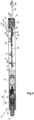
- an installation 6, comprising a closing, concealing or solar protection device 3, this installation 6 being in accordance with a first embodiment of the invention, installed in a building B comprising an opening 1, window or door.
- This installation 6 is equipped with a screen 2 belonging to the closing, concealing or solar protection device 3, in particular a motorized blind.
- the closing, concealing or sun protection device 3 is hereinafter called the “concealing device”.
- the concealing device 3 comprises the screen 2.
- the blackout device 3 may comprise a blind, in particular a canvas, roller blind, pleated blind or slatted blind.
- the present invention applies to all types of blackout device.
- roller blind which comprises an electromechanical actuator according to the first embodiment of the invention.
- the occulting device 3 comprises a winding tube 4 and a motorized drive device 5.
- the motorized drive device 5 comprises an electromechanical actuator 11, according to the first embodiment and illustrated in figures 3 to 7 .
- the screen 2 of the occulting device 3 is wound onto the winding tube 4 driven by the motorized drive device 5.
- the screen 2 is movable between a wound position, in particular high, and an unwound position, in particular low.
- the screen 2 of the occultation device 3 is a closing, occultation and/or sun protection screen, winding and unwinding around the winding tube 4, the inner diameter of which is greater than the outer diameter of the electromechanical actuator 11, so that the electromechanical actuator 11 can be inserted into the winding tube 4, when assembling the occultation device 3.
- the concealment device 3 comprises a holding device 9, 23.
- the holding device 9, 23 may comprise two supports 23.
- a support 23 is arranged at each end of the winding tube 4, in particular in an assembled configuration of the concealing device 3.
- the winding tube 4 is held by means of the supports 23. Only one of the supports 23 is visible at the Figure 1
- the supports 23 make it possible to mechanically connect the concealment device 3 to the structure of the building B, in particular to the wall M of the building B.
- the holding device 9, 23 may comprise a box 9. Furthermore, the winding tube 4 and at least part of the screen 2 are housed inside the box 9, in particular in the assembled configuration of the occulting device 3.
- the box 9 is arranged above the opening 1, or in the upper part of the opening 1.
- the supports 23 are also housed inside the box 9.
- the box 9 comprises two cheeks 10, as illustrated in the Figure 2 A cheek 10 is arranged at each end of the box 9, in particular in the assembled configuration of the concealment device 3.
- the winding tube 4 is held by means of the box 9, in particular by means of the cheeks 10 of the box 9, without using supports, such as the supports 23 mentioned above.
- the concealment device 3 can also comprise two lateral slides 26, as illustrated only in Figure 2 .
- Each side slide 26 comprises a groove 29.
- Each groove 29 of one of the side slides 26 cooperates, in other words is configured to cooperate with a lateral edge 2a of the screen 2, in particular in the assembled configuration of the occulting device 3, so as to guide the screen 2, during the winding and unwinding of the screen 2 around the winding tube 4.
- the electromechanical actuator 11 is, for example, of the tubular type. This makes it possible to rotate the winding tube 4 around an axis of rotation X, so as to unroll or roll up the screen 2 of the occulting device 3.
- the screen 2 can be rolled up and unrolled on the winding tube 4.
- the electromechanical actuator 11 is inserted into the winding tube 4.
- the occulting device 3 further comprises a load bar 8 for exerting tension on the screen 2.
- the roller blind which forms the blackout device 3, comprises a fabric, forming the screen 2 of the roller blind 3.
- a first end of the screen 2, in particular the upper end of the screen 2, in the assembled configuration of the blackout device 3, is fixed to the winding tube 4.
- a second end of the screen 2, in particular the lower end of the screen 2, in the assembled configuration of the blackout device 3, is fixed to the load bar 8.
- the canvas forming the screen 2 is made from a textile material.
- the first end of the screen 2 has a hem through which a rod, in particular made of plastic material, is arranged.
- This hem produced at the first end of the screen 2 is obtained by means of a seam of the fabric forming the screen 2.
- the hem and the rod located at the first end of the screen 2 are inserted by sliding into a groove provided on the external face of the winding tube 4, in particular over the entire length of the winding tube 4, so as to secure the screen 2 to the winding tube 4 and to be able to wind and unwind the screen 2 around the winding tube 4.
- the first end of the screen 2 is arranged at the level of the holding device 9, 23, in the sense that this first end remains above the opening 1 in the assembled configuration of the concealing device 3.
- the upper rolled-up position corresponds to a predetermined upper end-of-travel position, or to the loading bar 8 of the screen 2 resting against an edge of a box 9 of the roller blind 3
- the lower unrolled position corresponds to a predetermined lower end-of-travel position, or to the loading bar 8 of the screen 2 resting against a threshold 7 of the opening 1, or to the complete unrolling of the screen 2.
- the motorized drive device 5 is controlled by a control unit.
- the control unit may be, for example, a local control unit 12 or a central control unit 13.
- the local control unit 12 can be connected, by wired or wireless connection, with the central control unit 13.
- the central control unit 13 can control the local control unit 12, as well as other similar local control units distributed throughout the building.
- the motorized drive device 5 is preferably configured to execute the commands for unrolling or rolling up the screen 2 of the occulting device 3, which can be issued, in particular, by the local control unit 12 or the central control unit 13.
- the installation 6 comprises either the local control unit 12, or the central control unit 13, or the local control unit 12 and the central control unit 13.
- the electromechanical actuator 11 comprises an electric motor 16.
- the electric motor 16 is represented by its casing at Figure 4 , without details of its internal constituent elements, which are known per se.
- the electric motor 16 comprises a rotor and a stator, not shown, positioned coaxially around the axis of rotation X of the winding tube 4 in the mounted configuration of the motorized drive device 5.
- Means for controlling the electromechanical actuator 11, allowing the screen 2 of the occulting device 3 to be moved comprise at least one electronic control unit 15.
- This electronic control unit 15 is capable of starting the electric motor 16 of the electromechanical actuator 11, and, in particular, of allowing the electric motor 16 to be supplied with electrical energy.
- the electronic control unit 15 controls, in particular, the electric motor 16, so as to open or close the screen 2, as described previously.
- the control means of the electromechanical actuator 11 comprise hardware and/or software means.
- the hardware means may comprise at least one microcontroller 30.
- the electronic control unit 15 further comprises a first communication module 27, in particular for receiving commands from control, the control orders being issued by an order transmitter, such as the local control unit 12 or the central control unit 13, these orders being intended to control the motorized drive device 5.
- a first communication module 27 in particular for receiving commands from control, the control orders being issued by an order transmitter, such as the local control unit 12 or the central control unit 13, these orders being intended to control the motorized drive device 5.
- the first communication module 27 of the electronic control unit 15 is of the wireless type.
- the first communication module 27 is configured to receive radio control commands.
- the first communication module 27 can also allow the reception of control orders transmitted by wired means.
- the electronic control unit 15, the local control unit 12 and/or the central control unit 13 can be in communication with a weather station arranged inside the building B or remote outside the building B, including, in particular, one or more sensors which can be configured to determine, for example, a temperature, a brightness, or even a wind speed, in the case where the weather station is remote outside the building B.
- the electronic control unit 15, the local control unit 12 and/or the central control unit 13 can also be in communication with a server 28, as illustrated in Figure 2 , so as to control the electromechanical actuator 11 according to data made available remotely via a communication network, in particular an internet network which can be connected to the server 28.
- a communication network in particular an internet network which can be connected to the server 28.
- the electronic control unit 15 can be controlled from the local control unit 12 and/or central control unit 13.
- the local control unit 12 and/or central control unit 13 is provided with a control keyboard.
- the control keyboard of the local control unit 12 or central control unit 13 comprises one or more selection elements 14 and, optionally, one or more display elements 34.
- the selection elements may comprise push buttons and/or touch keys.
- the display elements may comprise light-emitting diodes and/or an LCD (acronym for the English term “Liquid Crystal Display”) or TFT (acronym for the English term “Thin Film Transistor”) display.
- the selection and display elements may also be implemented using a touch screen.
- the local control unit 12 and/or central control unit 13 comprises at least one second communication module 36.
- the second communication module 36 of the local control unit 12 or central control unit 13 is configured to transmit, in other words emit, control orders, in particular by wireless means, for example radioelectric, or by wired means.
- the second communication module 36 of the local control unit 12 or central control unit 13 can also be configured to receive, in other words receives, control orders, in particular via the same means.
- the second communication module 36 of the local control unit 12 or central control unit 13 is configured to communicate, in other words communicates, with the first communication module 27 of the electronic control unit 15.
- the second communication module 36 of the local control unit 12 or central control unit 13 exchanges control orders with the first communication module 27 of the electronic control unit 15, either unidirectionally or bidirectionally.
- the local control unit 12 is a control point, which may be fixed or mobile.
- a fixed control point may be a control box intended to be fixed on a facade of the wall M of the building B or on a face of a fixed frame of a window or a door.
- a mobile control point may be a remote control, a smartphone or a tablet.
- the local control unit 12 and/or central control unit 13 further comprises a controller 35.
- the motorized drive device 5, in particular the electronic control unit 15, is preferably configured to execute movement control orders, in particular closing and opening, of the screen 2 of the occulting device 3. These control orders can be issued, in particular, by the local control unit 12 or by the central control unit 13.
- the motorized drive device 5 can be controlled by the user, for example by receiving a control command corresponding to pressing the or one of the selection elements 14 of the local 12 or central 13 control unit.
- the motorized drive device 5 can also be controlled automatically, for example by receiving a control command corresponding to at least one signal from at least one sensor, not shown, and/or to a signal from a clock, not shown, of the electronic control unit 15, in particular of the microcontroller 30.
- the sensor and/or the clock can be integrated into the local control unit 12 or into the central control unit 13.
- the electromechanical actuator 11 comprises a casing 17, in particular a tubular casing.
- the electric motor 16 is mounted inside the casing 17, in particular in an assembled configuration of the electromechanical actuator 11.
- the casing 17 of the electromechanical actuator 11 is cylindrical in shape, in particular of revolution around the axis of rotation X.
- the casing 17 is made of a metallic material.
- the material of the electromechanical actuator housing is not limiting and may be different. In particular, it may be a plastic material.
- the occultation device 3 further comprises an electrical energy supply device 31.
- the electromechanical actuator 11 is configured to be electrically connected, in other words is electrically connected, to the electrical energy supply device 31.
- the electromechanical actuator 11 further comprises first electrical conductors 37.
- the first electrical conductors 37 extend between the electronic control unit 15 and the electric motor 16, as illustrated in the central part of the Figure 4 .
- the electromechanical actuator 11 further comprises an electrical power supply cable 18.
- the electrical power supply cable 18 comprises at least second electrical conductors 38.
- the second electrical conductors 38 are visible at figures 4 And 5 , at one end of the power supply cable 18.
- the first electrical conductors 37 are configured to be connected to an electrical power supply network 52, by means of the second electrical conductors 38.
- the electric motor 16 is supplied with electrical energy via the first electrical conductors 37, themselves electrically connected to the second electrical conductors 38.
- the electric motor 16 is configured to be supplied with electrical energy, in other words is supplied with electrical energy, by the electrical energy supply network 52, through the electrical power supply cable 18.
- the first electrical conductors 37 of the electromechanical actuator 11 are configured to be electrically connected, in other words are electrically connected, to the second electrical conductors 38 of the electrical power supply cable 18.
- the second electrical conductors 38 of the electrical power supply cable 18 are configured to be electrically connected, in other words are electrically connected, to third electrical conductors 39 of the electrical power supply network 52, for example by means of electrical connectors, such as the first electrical connector 55 of the electrical power supply cable 18 illustrated in figures 3 And 4 .
- the electromechanical actuator 11 further comprises the electronic control unit 15.
- the electronic control unit 15 comprises a first electronic card 15a and a second electronic card 15b.
- the electronic control unit 15 and, more particularly, each of the first and second electronic cards 15a, 15b comprises at least one printed circuit board 40a, 40b.
- the or each printed circuit board 40a, 40b is equipped with electronic components 56.
- the first electrical conductors 37 are configured to electrically connect, in other words electrically connect, the electrical power supply cable 18 to the electronic control unit 15, in particular to the first and second electronic cards 15a, 15b and, more particularly, to the printed circuit board 40a, 40b of each of these first and second electronic cards 15a, 15b.
- the first electrical conductors 37 are made by means of electrical wires and/or electrical tracks of the or each printed circuit board 40a, 40b of the electronic control unit 15. Only the part of the first electrical conductors 37 made by means of electrical wires is visible at the Figure 4 .
- the electrical power supply cable 18, in particular the second electrical conductors 38 are electrically connected, in other words are configured to be electrically connected, to electrical tracks, not shown, of the first printed circuit board 40a by means of a second electrical connector 59 of the electrical power supply cable 18, as illustrated in figures 4 And 5 , and an electrical connector 60 of the first electronic card 15a, as illustrated in Figure 4 .
- the electrical connector 60 of the first electronic card 15a has been omitted at the Figure 5 , just like the 56 electronic components of it.
- the voltage of the electrical power supply network 52 is, preferably, continuous and called “very low voltage”.
- the value of the voltage of the electrical power supply network 52 is, preferably, less than or equal to 120 volts and, more particularly, less than or equal to 50 volts.
- the value of the voltage of the electrical power supply network 52 may be, for example, of the order of 12 volts, 24 volts or 48 volts.
- the electrical power supply network 52 may be a so-called “PoE” network (acronym for the English term Power over Ethernet).
- the electric motor 16 can be of the brushless type with electronic commutation, also called “BLDC” (acronym for the English term BrushLess Direct Current) or “synchronous with permanent magnets”, or of the direct current type.
- BLDC brushless type with electronic commutation
- synchronous with permanent magnets or of the direct current type.
- the electrical power supply device 31 can include at least a 24 battery.
- the battery 24 can be arranged at the level of the box 9 of the occulting device 3.
- the battery 24 can thus be arranged inside or outside the box 9.
- the battery 24 can also be arranged inside the winding tube 4, while being outside the casing 17.
- the electromechanical actuator 11 can also comprise the battery 24.
- the battery 24 can thus be arranged inside the casing 17, in particular in the assembled configuration of the electromechanical actuator 11.
- the electrical energy supply device 31 may further comprise at least one concentrator 57 and, optionally, at least one adapter 58, in particular in the case where the electromechanical actuator 11 is configured to be electrically connected, in other words is electrically connected, to an electrical energy supply network known as “PoE”.
- the electrical power supply cable 18 is configured to supply electrical energy, in other words supplies electrical energy, to the electromechanical actuator 11, in particular the electronic control unit 15 and the electric motor 16, in particular from the electrical power supply device 31, in particular from the battery 24.
- the battery 24 comprises one or more energy storage elements.
- the energy storage elements of the battery 24 may be, in particular, rechargeable accumulators, in the case where the battery 24 is of the rechargeable type, or even batteries.
- the motorized drive device 5 and, in particular, the electronic control unit 15, comprises charging elements configured to charge the battery 24 from the electrical energy supplied by an external electrical energy supply source 25, as illustrated in FIG. Figure 2 .
- the external electrical power supply source 25 is a charger that can be plugged into a wall electrical outlet, so as to recharge the battery 24 from a mains electrical power supply network.
- the loading elements are arranged at the level of the second electronic card 15b.
- the electromechanical actuator 11 further comprises an output shaft 20.
- the electromechanical actuator 11 further comprises a reducer 19.
- the reducer 19 comprises at least one reduction stage.
- the reduction stage may be an epicyclic type gear train.
- the type and number of reduction stages of the reducer are not limiting.
- the electromechanical actuator 11 further comprises a brake 32.
- the brake 32 may be a spring brake, a cam brake, a magnetic brake or an electromagnetic brake.
- the brake 32 is configured to brake and/or to lock the output shaft 20 in rotation, so as to regulate the speed of rotation of the winding tube 4, during a movement of the screen 2, and to keep the winding tube 4 locked, when the electromechanical actuator 11 is electrically deactivated.
- the brake 32 is configured to be arranged, in other words is arranged, between two reduction stages 19a, 19b of the reducer 19.
- the brake 32 is configured to be arranged, in other words is arranged, between the electronic control unit 15 and the electric motor 16, in other words at the input of the electric motor 16, between the reducer 19 and the output shaft 20, in other words at the output of the reducer 19, or between the electric motor 16 and the reducer 19, that is to say at the output of the electric motor 16.
- the reducer 19 and, possibly, the brake 32 are arranged inside the casing 17 of the electromechanical actuator 11, in particular in the assembled configuration of the electromechanical actuator 11.
- the winding tube 4 is rotated about the rotation axis X and the casing 17 of the electromechanical actuator 11 while being supported by means of two pivot connections.
- the first pivot connection is made at a first end of the winding tube 4 by means of a crown 53.
- the crown 53 thus makes it possible to make a bearing.
- the second pivot connection is made at a second end of the winding tube 4.
- the electromechanical actuator 11 further comprises a torque support 21, which may also be called an “actuator head”.
- the torque support 21 is arranged at the first end 17a of the casing 17 of the electromechanical actuator 11, in particular in the assembled configuration of the electromechanical actuator 11.
- the torque support 21 makes it possible to take up the forces exerted by the electromechanical actuator 11 and, in particular, to ensure the take-up of the forces exerted by the electromechanical actuator 11, in particular the torque exerted by the electromechanical actuator 11, by the structure of the building B.
- the torque support 21 advantageously makes it possible to take up, in addition, forces exerted by the winding tube 4, in particular the weight of the winding tube 4, of the electromechanical actuator 11 and of the screen 2, and to ensure the take-up of these forces by the structure of the building B.
- the torque support 21 of the electromechanical actuator 11 makes it possible to fix the electromechanical actuator 11 to the holding device 9, 23, in particular to one of the supports 23 or to one of the cheeks 10 of the box 9.
- the torque support 21 projects at the first end 17a of the casing 17 of the electromechanical actuator 11, in particular the end 17a of the casing 17 receiving the crown 53.
- the crown 53 constitutes, in other words is configured to constitute, a bearing for guiding the winding tube 4 in rotation, in particular in the assembled configuration of the concealing device 3.
- the torque support 21 of the electromechanical actuator 11 can also make it possible to close the first end 17a of the casing 17.
- the torque support 21 of the electromechanical actuator 11 can make it possible to support at least part of the electronic control unit 15.
- the torque support 21 is fixed to the casing 17 by means of one or more fixing elements 54, in particular in the assembled configuration of the electromechanical actuator 11.
- the fixing element(s) 54 may be, in particular, bosses, as illustrated in Figure 3 , fixing screws, elastic snap-on fixing elements, grooves fitted into notches or a combination of these different fixing elements.
- the torque support 21 comprises a first part 21a and a second part 21b.
- the first part 21a of the torque support 21 is configured to cooperate, in other words cooperates, with the casing 17 of the electromechanical actuator 11, in particular in the assembled configuration of the electromechanical actuator 11.
- the second part 21b of the torque support 21 is configured to cooperate, in other words cooperates, with the holding device 9, 23, in particular in an assembled configuration of the electromechanical actuator 11 in the device occultation 3.
- the production of the torque support 21 comprising the first and second parts 21a, 21b in a single piece makes it possible to improve the rigidity of the torque support 21.
- At least a portion of the first part 21a of the torque support 21 is of generally cylindrical shape and is arranged inside the casing 17 of the electromechanical actuator 11, in particular in the assembled configuration of the electromechanical actuator 11.
- an outer diameter of at least a portion of the second part 21b of the torque support 21 is greater than an outer diameter of the casing 17 of the electromechanical actuator 11.
- the torque support 21 further comprises a stop 33.
- the stop 33 is in support, in other words is configured to be in support, with the casing 17, at the level of the first end 17a of the casing 17, in particular in the assembled configuration of the electromechanical actuator 11.
- the stop 33 of the torque support 21 makes it possible to limit the sinking of the first part 21a of the torque support 21 into the casing 17, in the direction of the axis of rotation X.
- stop 33 of the torque support 21 delimits the first and second parts 21a, 21b of the torque support 21 relative to each other.
- the first part 21a of the torque support 21 is arranged inside the casing 17 of the electromechanical actuator 11, following the fitting of the torque support 21 inside the casing 17, up to the stop 33, in particular in the assembled configuration of the electromechanical actuator 11.
- the stop 33 of the torque support 21 comprises a shoulder and, more particularly, it is produced in the form of a collar, in particular of cylindrical shape and with a rectilinear generatrix.
- the crown 53 is inserted around the torque support 21, in particular the second part 21b of the torque support 21, in particular in the assembled configuration of the electromechanical actuator 11.
- the crown 53 is inserted around a first end 17a of the casing 17 of the electromechanical actuator 11, in particular in the assembled configuration of the electromechanical actuator 11.
- the electronic control unit 15, in particular the first and second electronic cards 15a, 15, are supplied with electrical energy by means of the electrical power supply cable 18.
- the electronic control unit 15 is arranged at least partly inside the casing 17 of the electromechanical actuator 11.
- the electronic control unit 15 may be arranged at least partly outside the casing 17 of the electromechanical actuator 11 and, in particular, mounted in the torque support 21.
- the first electronic card 15a of the electronic control unit 15 is arranged inside the casing 17 of the electromechanical actuator 11, in particular in the assembled configuration of the electromechanical actuator 11. Furthermore, the second electronic card 15b is arranged inside the torque support 21 of the electromechanical actuator 11, in particular in the assembled configuration of the electromechanical actuator 11.
- the electronic control unit 15 is devoid of a housing for receiving the first electronic card 15a.
- This first electronic card 15a is, on the one hand, held, in particular plugged, in the torque support 21, in particular in a third central part 21c of the torque support 21, as illustrated in figures 4 And 5 , and, on the other hand, maintained, in particular plugged, in a support, not shown, mounted at the end of the electric motor 16, in particular in the assembled configuration of the electromechanical actuator 11.
- the torque support 21 further comprises a cover 22. Furthermore, the cover 22 is mounted on the second part 21b of the torque support 21, in particular in the assembled configuration of the electromechanical actuator 11.
- the second electronic card 15b is arranged inside a recess 43 formed between the second part 21b of the torque support 21 and the cover 22.
- the torque support 21 comprises at least one selection device 41, in particular a button, which may be, for example, of the push-button type.
- This or these selection devices 41 are configured to carry out an adjustment of the electromechanical actuator 11 through one or more configuration modes, pair with the electromechanical actuator 11 one or more control units 12, 13, reset one or more parameters, which may be, for example, an end-of-travel position, reset the paired control unit(s) 12, 13 or even control the movement of the screen 2.
- the torque support 21 comprises a single selection device 41.
- the number of torque support selection devices is not limiting and may be different. It may be, in particular, greater than or equal to two.
- the torque support 21 comprises at least one display device 42.
- This or these display devices 42 are configured to display a visual indication, which may be, for example, representative of an operating mode of the electromechanical actuator 11, in particular a configuration mode or a control mode, or even of a state of a member of the motorized drive device 5 or of the electrical energy supply device 31, in particular a state of charge of the battery 24.
- the display device 42 comprises at least one lighting source, not shown, in particular a light-emitting diode, mounted on the second electronic card 15b and, optionally, a transparent or translucent cover and/or a light guide, to allow the passage of the light emitted by the lighting source.
- a lighting source not shown, in particular a light-emitting diode, mounted on the second electronic card 15b and, optionally, a transparent or translucent cover and/or a light guide, to allow the passage of the light emitted by the lighting source.
- the torque support 21 comprises a single display device 42.
- the number of display devices is not limiting and may be different. It may be, in particular, greater than or equal to two.
- the selection device 41 and the display device 42 are electrically connected, in other words are configured to be electrically connected, to the electronic control unit 15.
- the selection device 41 and the display device 42 are electrically connected, in other words are configured to be electrically connected, to the second electronic control card 15b.
- the selection device 41 and/or the display device 42 may be electrically connected, in other words may be configured to be electrically connected, to the first electronic control card 15a.
- the torque support 21 may comprise either the selection device(s) 41 or the display device(s) 42, or the selection device(s) 41 and the display device(s) 42.
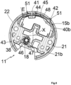
- the torque support 21 comprises at least one housing 44. Furthermore, the housing 44 houses, in other words is configured to house, at least the selection device(s) 41 or the display device(s) 42, in particular in the assembled configuration of the electromechanical actuator 11.
- the housing 44 receives, in other words is configured to receive, at least one of the selection device(s) 41 and the display device(s) 42, in particular in the assembled configuration of the electromechanical actuator 11.
- the torque support 21 comprises a single housing 44, where the selection device 41 and the display device 42 are housed.
- the torque support 21 may comprise a first housing 44 for the selection device 41 and a second housing 44 for the display device 42.
- the torque support 21 may further comprise a first housing 44 per selection device 41 or for a plurality of selection devices 41, in the case where the torque support 21 has several selection devices 41, and a second housing 44 per display device 42 or for a plurality of display devices 42, in the case where the torque support 21 has several display devices 42.
- the output shaft 20 of the electromechanical actuator 11 is arranged inside the winding tube 4 and at least partly outside the casing 17 of the electromechanical actuator 11.
- one end of the output shaft 20 projects relative to the casing 17 of the electromechanical actuator 11, in particular relative to a second end 17b of the casing 17 opposite the first end 17a.
- the electric motor 16 and the reduction gear 19 rotate the output shaft 20.
- the output shaft 20 of the electromechanical actuator 11 rotates the winding tube 4 via the connecting element.
- the winding tube 4 rotates the screen 2 of the occulting device 3, so as to open or close the opening 1.
- the electronic control unit 15 of the electromechanical actuator 11 comprises an obstacle detection and end-of-travel device, not shown, during the rolling up of the screen 2 and during the unrolling of this screen 2.
- the obstacle detection and end-of-travel device during the rolling and unrolling of the screen 2 is implemented by means of the microcontroller 30 of the electronic control unit 15 and, in particular, by means of an algorithm implemented by this microcontroller 30.
- the power supply cable 18 comprises at least one shield 46.
- the second electrical conductors 38 are arranged at inside the shield 46 of the power supply cable 18.
- the electrical power cable 18 further comprises an insulating sheath 47. Furthermore, the shielding 46 is provided between the insulating sheath 47 and the second electrical conductors 38.
- the electrical power cable 18 may comprise at least the second electrical conductors 38, a dielectric material, not shown, in other words an insulating material, the shielding 46 and the insulating sheath 47.
- the second electrical conductors 38 are surrounded by the dielectric material.
- the dielectric material is surrounded by the shielding 46.
- the shielding 46 is surrounded by the insulating sheath 47.
- the shielding 46 may be made of a conductive braid, which may be, for example, made of copper.
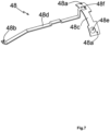
- the electrostatic charge discharge device 45 comprises at least one electrical connection element 48, shown alone in the Figure 7
- the electrical connecting element 48 electrically connects, in other words is configured to electrically connect, the housing 44 of the torque support 21 to the shielding 46 of the electrical power supply cable 18, in particular to a first end of the shielding 46 of the electrical power supply cable 18.
- the electrostatic charge discharge device 45 comprises a single electrical connection element 48.
- the number of electrical connection elements is not limiting and may be different. It may be, in particular, greater than or equal to two.
- the evacuation of electrostatic charges through the electrical connection element 45 makes it possible to create a preferential discharge path between the housing 44 of the torque support 21 and the shielding 46 of the electrical power supply cable 18.
- the evacuation of electrostatic charges through the electrical connection element 48 arranged inside the electromechanical actuator 11, in particular the torque support 21 and, possibly, the casing 17, makes it possible to avoid malfunctions and/or damage to the electromechanical actuator 11 and, in particular, to prevent the destruction of electronic components 56 mounted on the printed circuit board(s) 40a, 40b, in particular one or other of the first and second electronic cards 15a, 15b of the electronic control unit 15.
- the electrical connection element 48 arranged inside the electromechanical actuator 11 makes it possible to discharge electrostatic charges accumulated in the screen 2 of the concealment device 3 of the installation 6.
- the electrical connecting element 48 arranged inside the electromechanical actuator 11 makes it possible to protect the electronic control unit 15 from the electromechanical actuator 11, in particular the first and second electronic cards 15a, 15b.
- the electrical connection element 48 makes it possible to limit overvoltages at the level of the electronic components 56 mounted on the printed circuit board(s) 40a, 40b, in particular of one or other of the first and second electronic cards 15a, 15b of the electronic control unit 15, so as to protect the electronic control unit 15.
- Such an electrostatic charge discharge device 45 produced by means of the electrical connection element 48 electrically connecting the housing 44 of the torque support 21 to the shielding 46 of the electrical power supply cable 18 is inexpensive, simple to industrialize and makes it possible to minimize the costs of obtaining the electromechanical actuator 11.
- the electrical connecting element 48 is made of a metallic material, in particular electrically conductive, which may be, for example, copper, brass or even steel.
- the electrical connection element 48 is a rigid element, in particular a first blade, for example metallic.
- the electronic control unit 15 further comprises a first electrical connection element 49, in particular a second blade, for example metallic, and a second electrical connection element 50.
- the first electrical connection element 49 is mounted on the printed circuit board 40a, in particular of the first electronic card 15a, in particular in an assembled configuration of the electronic control unit 15.
- the electrical connection element 48 is electrically connected to the first electrical connection element 49, in particular brought into electrical contact with the first electrical connection element 49, in particular in the assembled configuration of the electromechanical actuator 11.
- the second electrical connection element 50 is electrically connected to the first electrical connection element 49, in particular electrically connected with the first electrical connection element 49, in particular in the assembled configuration of the electromechanical actuator 11.
- the second electrical connection element 50 is electrically connected to the shielding 46 of the electrical power supply cable. 18, in particular in the assembled configuration of the electromechanical actuator 11.
- the electrical connection element 48 extends from the housing 44 of the torque support 21 to the first electrical connection element 49 of the electronic control unit 15, in particular in the assembled configuration of the electromechanical actuator 11.
- the electrical connecting element 48 extends inside the first and second parts 21a, 21b of the torque support 21 and, consequently, partially inside the casing 17.
- the electrical connection element 48 comprises at least a first end 48a and a second end 48b.
- the first end 48a of the electrical connection element 48 is arranged at the housing 44 of the torque support 21, in particular inside this housing 44.
- the second end 48b of the electrical connection element 48 is arranged at the first electrical connection element 49 of the electronic control unit 15, in particular in electrical contact with the first electrical connection element 49 of the electronic control unit 15 and in this case of the first electronic card 15a.
- the housing 44 of the torque support 21 has at least one opening 51 or at least one wall, not shown, in particular of small thickness, which may be, for example, less than or equal to one millimeter thick, through which the electrostatic charges coming from the screen 2 circulate and are introduced into this housing 44.
- the first end 48a of the electrical connection element 48 is distant from the opening 51 or from the wall of the housing 44 of the torque support 21 by a determined spacing E.
- the spacing E is measured radially to the axis of rotation X.
- the spacing E can, as a variant not shown, be measured in another direction.
- the spacing E is determined based on a creepage distance value.
- the spacing E makes it possible to respect the electrical insulation distances and to evacuate electrostatic charges from a threshold value of electric current.
- the value of the spacing E is of the order of three millimeters, so as to respect a creepage line of five millimeters.
- the discharge of the electrostatic charges is implemented by the circulation of an electric current from the screen 2 then passing through the housing 44 of the torque support 21, in the electrical connection element 48, in the first and second electrical connection elements 49, 50 of the electronic control unit 15 and in the shielding 46 of the electrical power supply cable 18.
- the shielding 46 of the electrical power supply cable 18, in particular a second end thereof, is further configured to be electrically connected, in other words is electrically connected, to an earth, in particular an earth of the installation 6, in a mounted state of the electromechanical actuator 11 in the installation 6.
- the casing 17 of the electromechanical actuator 11 is not electrically connected to the ground.
- the electromechanical actuator 11 can be electrically connected to the electrical power supply network 52 without requiring an electrical ground conductor, both at the electromechanical actuator 11 and at the electrical power supply network 52, when installing the electromechanical actuator 11, so as to simplify the installation of the electromechanical actuator 11 and reduce the costs of obtaining the electromechanical actuator 11.
- the electrical connection element 48 is placed in electrical contact, in other words is configured to be placed in electrical contact, with the first electrical connection element 49 of the electronic control unit 15, in particular of the first electronic card 15a, during the assembly of the torque support 21 on the casing 17.
- the electrical connection element 48 is “L” or “T” shaped, in other words it has a first branch 48c and a second branch 48d, which may be, for example, perpendicular to each other.
- the first branch 48c can thus be made so as to be arranged, on the one hand, opposite the selection device 41 and, on the other hand, opposite the display device 42.
- the first branch 48c comprises two first ends 48a arranged at the level of the housing 44 of the torque support 21, to evacuate the electrostatic charges passing from the screen 2 to this housing 44 at the level of the selection device 41 and at the level of the display device 42.
- the second end 48b is arranged at one end of the second branch 48d, in particular the end of the second branch 48d opposite the end of the second branch 48d intended for the junction of the first branch 48c with the second branch 48d.
- the electrical connection element 48 in particular the first branch 48c, comprises at least one opening 48e, 48f. Furthermore, the or each opening 48e, 48f is configured to be crossed, in other words is crossed, by a selection device 41 or a display device 42, in particular in the assembled configuration of the electromechanical actuator 11.
- the number and arrangement of the opening(s) 48e, 48f of the electrical connection element 48 are adapted to the number and arrangement of the selection device(s) 41 and/or the display device(s) 42.
- the electrical connection element 48 is a flexible element, in particular an electric wire.
- the electrical connection element 48 is connected directly, by its second end 48b, to the shielding 46 of the electrical power supply cable 18.
- the discharge of the electrostatic charges is implemented by the circulation of an electric current from the screen 2 then passing through the housing 44 of the torque support 21, in the electrical connection element 48 and in the shielding 46 of the electrical power supply cable 18, without passing through elements mounted on the first electronic card 15a, in particular the first printed circuit board 40a.
- the evacuation of electrostatic charges through the electrical connection element makes it possible to create a preferential discharge path between the housing of the torque support and the shielding of the electrical power supply cable.
- the evacuation of electrostatic charges through the electrical connection element arranged inside the electromechanical actuator, in particular the torque support and, possibly, the casing makes it possible to avoid malfunctions and/or damage to the electromechanical actuator and, in particular, to prevent the destruction of electronic components mounted on one or more printed circuit boards of the electronic control unit.
- the electronic control unit 15 further comprises a housing. Furthermore, the first electronic card 15a is arranged inside the housing, in particular in the assembled configuration of the electronic control unit 15.
- the housing of the electronic control unit 15 makes it possible to protect the first electronic card 15a, during the assembly of the electromechanical actuator 11 and following the assembly of the latter.
- the housing of the electronic control unit 15 makes it possible to electrically isolate the first electronic card 15a from the casing. 17.
- the outer diameter of the housing of the electronic control unit 15 is smaller than the inner diameter of the casing 17, so that the housing can be inserted into the casing 17, during the assembly of the electromechanical actuator 11.
- the housing of the electronic control unit 15 may comprise two half-shells configured to cooperate together, in particular in the assembled configuration of the electronic control unit 15.
- the two half-shells are assembled together, so as to define a junction plane extending in a direction parallel to the axis of rotation X.
- at least one of the two half-shells forming the housing comprises elements for positioning and fixing the first electronic card 15a, in particular the first printed circuit board 40a, in particular in the assembled configuration of the electronic control unit 15.
- the housing of the electronic control unit 15 may comprise one or more sections, the or each section being made in the form of a hollow tube.
- the or each section is configured to house or receive, in other words houses or receives, the first electronic card 15a, in particular in the assembled configuration of the electronic control unit 15.
- the or each section of the housing comprises a first groove and a second groove.
- the first and second grooves are configured to hold in position, in other words hold in position, the first electronic card 15a, in particular the first printed circuit board 40a, inside the housing, in particular in the assembled configuration of the electronic control unit 15.
- the electromechanical actuator 11 is inserted into a rail, in particular of square or rectangular section, which can be open at one or both of its ends, in particular in the assembled configuration of the occulting device 3. Furthermore, the electromechanical actuator 11 can be configured to drive a drive shaft on which cords for moving and/or orienting the screen 2 are wound.
Landscapes
- Engineering & Computer Science (AREA)
- Structural Engineering (AREA)
- Architecture (AREA)
- Civil Engineering (AREA)
- Operating, Guiding And Securing Of Roll- Type Closing Members (AREA)
- Casings For Electric Apparatus (AREA)
- User Interface Of Digital Computer (AREA)
- Instrument Panels (AREA)
Claims (10)
- Elektromechanischer Aktuator (11) für eine Verschluss-, Verdunkelungs- oder Sonnenschutzanlage (1),der elektromechanische Aktuator (11) mindestens umfassend:- ein Gehäuse (17),- eine Drehmomentstütze (21), wobei die Drehmomentstütze (21) an einem ersten Ende (17a) des Gehäuses (17) angeordnet ist,- ein Stromversorgungskabel (18), wobei das Stromversorgungskabel (18) konfiguriert ist, um mit einem elektrischen Stromversorgungsnetz (52) verbunden zu werden,- einen Elektromotor (16), wobei der Elektromotor (16) innerhalb des Gehäuses (17) montiert ist, wobei der Elektromotor (16) über das Stromversorgungskabel (18) mit elektrischer Energie versorgt wird, und- eine elektronische Steuereinheit (15), und- eine Vorrichtung zum Ableiten elektrostatischer Ladungen (45),dadurch gekennzeichnet,dass die Drehmomentstütze (21) Folgendes umfasst:- entweder mindestens eine Auswahlvorrichtung (41) oder mindestens eine Anzeigevorrichtung (42) oder mindestens eine Auswahlvorrichtung (41) und mindestens eine Anzeigevorrichtung (42), und- mindestens eine Aufnahme (44), wobei die Aufnahme (44) mindestens die Auswahlvorrichtung (41) oder die Anzeigevorrichtung (42) aufnimmt,dass das Stromversorgungskabel (18) mindestens eine Abschirmung (46) umfasst, und dass die Vorrichtung zur Ableitung elektrostatischer Ladungen (45) mindestens ein elektrisches Verbindungselement (48) umfasst, wobei das elektrische Verbindungselement (48) die Aufnahme (44) der Drehmomentstütze (21) elektrisch mit der Abschirmung (46) des Stromversorgungskabels (18) verbindet.
- Elektromechanischer Aktuator (11) einer Verschluss-, Verdunkelungs- oder Sonnenschutzanlage (1) nach Anspruch 1, dadurch gekennzeichnet, dass das elektrische Verbindungselement (48) ein starres Element, insbesondere eine Lamelle, ist.
- Elektromechanischer Aktuator (11) einer Verschluss-, Verdunkelungs- oder Sonnenschutzanlage (1) nach Anspruch 1, dadurch gekennzeichnet, dass das elektrische Verbindungselement (48) ein flexibles Element, insbesondere ein elektrischer Draht, ist.
- Elektromechanischer Aktuator (11) einer Verschluss-, Verdunkelungs- oder Sonnenschutzanlage (1) nach einem der Ansprüche 1 bis 3, dadurch gekennzeichnet- dass die elektronische Steuereinheit (15) mindestens Folgendes umfasst:- eine Leiterplatte (40a, 40b),- ein erstes elektrisches Verbindungselement (49), wobei das erste elektrische Verbindungselement (49) auf der Leiterplatte (40a) montiert ist, und- ein zweites elektrisches Verbindungselement (50), wobei das zweite elektrische Verbindungselement (50) elektrisch mit dem ersten elektrischen Verbindungselement (49) verbunden ist,- dass das elektrische Verbindungselement (48) elektrisch mit dem ersten elektrischen Verbindungselement (49) verbunden ist,- und dass das zweite elektrische Verbindungselement (50) elektrisch mit der Abschirmung (46) des Stromversorgungskabels (18) verbunden ist.
- Elektromechanischer Aktuator (11) einer Verschluss-, Verdunkelungs- oder Sonnenschutzanlage (1) nach Anspruch 4, dadurch gekennzeichnet, dass sich das elektrische Verbindungselement (48) von der Aufnahme (44) der Drehmomentstütze (21) bis zu dem ersten elektrischen Verbindungselement (49) der elektronischen Steuereinheit (15) erstreckt.
- Elektromechanischer Aktuator (11) einer Verschluss-, Verdunkelungs- oder Sonnenschutzanlage (1) nach einem der Ansprüche 1 bis 5, dadurch gekennzeichnet- dass die elektronische Steuereinheit (15) eine erste elektronische Leiterplatte (15a) und eine zweite elektronische Leiterplatte (15b) umfasst,- dass die erste elektronische Leiterplatte (15a) im Inneren des Gehäuses (17) angeordnet ist,- und dass die zweite elektronische Leiterplatte (15b) im Inneren der Drehmomentstütze (21) angeordnet ist.
- Elektromechanischer Aktuator (11) einer Verschluss-, Verdunkelungs- oder Sonnenschutzanlage (1) nach einem der Ansprüche 1 bis 6, dadurch gekennzeichnet- dass die Drehmomentstütze (21) einen ersten Teil (21a), einen zweiten Teil (21b) und einen Deckel (22) umfasst,- und dass der Deckel (22) an dem zweiten Teil (21b) der Drehmomentstütze (21) montiert ist.
- Elektromechanischer Aktuator (11) einer Verschluss-, Verdunkelungs- oder Sonnenschutzanlage (1) nach Anspruch 6 und nach Anspruch 7, dadurch gekennzeichnet, dass die zweite elektronische Leiterplatte (15b) im Inneren einer Aussparung (43) angeordnet ist, die zwischen dem zweiten Teil (21b) der Drehmomentstütze (21) und dem Deckel (22) gebildet ist.
- Elektromechanischer Aktuator (11) einer Verschluss-, Verdunkelungs- oder Sonnenschutzanlage (1) nach einem der Ansprüche 1 bis 8, dadurch gekennzeichnet- dass die Drehmomentstütze (21) ferner einen Anschlag (33) umfasst,- und dass der Anschlag (33) an dem ersten Ende (17a) des Gehäuses (17) an dem Gehäuse (17) anliegt.
- Verschluss-, Verdunkelungs- oder Sonnenschutzanlage (6), umfassend einen Schirm (2), der durch einen elektromechanischen Aktuator (11) zur Bewegung angetrieben wird, dadurch gekennzeichnet, dass der elektromechanische Aktuator (11) einem der Ansprüche 1 bis 9 entspricht.
Applications Claiming Priority (1)
| Application Number | Priority Date | Filing Date | Title |
|---|---|---|---|
| FR2012553A FR3116956B1 (fr) | 2020-12-02 | 2020-12-02 | Actionneur électromécanique et installation de fermeture, d’occultation ou de protection solaire comprenant un tel actionneur électromécanique |
Publications (2)
| Publication Number | Publication Date |
|---|---|
| EP4008876A1 EP4008876A1 (de) | 2022-06-08 |
| EP4008876B1 true EP4008876B1 (de) | 2025-06-04 |
Family
ID=74554017
Family Applications (1)
| Application Number | Title | Priority Date | Filing Date |
|---|---|---|---|
| EP21211818.6A Active EP4008876B1 (de) | 2020-12-02 | 2021-12-01 | Elektromechanisches stellglied und verschluss-, verdunkelungs- oder sonnenschutzanlage, die ein solches stellglied umfasst |
Country Status (2)
| Country | Link |
|---|---|
| EP (1) | EP4008876B1 (de) |
| FR (2) | FR3116956B1 (de) |
Families Citing this family (2)
| Publication number | Priority date | Publication date | Assignee | Title |
|---|---|---|---|---|
| FR3136500B1 (fr) * | 2022-06-08 | 2024-06-14 | Somfy Activites Sa | Actionneur électromécanique et dispositif d’occultation comprenant un tel actionneur |
| FR3140109B1 (fr) | 2022-09-23 | 2024-10-04 | Somfy Activites Sa | Actionneur électromécanique et dispositif d’occultation comprenant un tel actionneur électromécanique |
Family Cites Families (5)
| Publication number | Priority date | Publication date | Assignee | Title |
|---|---|---|---|---|
| US9822584B2 (en) * | 2014-05-19 | 2017-11-21 | The Watt Stopper, Inc. | Electrostatic discharge protection system for window coverings |
| US10519713B2 (en) * | 2015-07-01 | 2019-12-31 | Hunter Douglas Inc. | Static mitigation end cap for a covering for an architectural opening |
| FR3055506B1 (fr) * | 2016-08-26 | 2018-09-28 | Somfy Sas | Actionneur electromecanique tubulaire et installation domotique comprenant un tel actionneur |
| FR3072116B1 (fr) * | 2017-10-10 | 2019-11-08 | Somfy Activites Sa | Actionneur electromecanique tubulaire et installation domotique comprenant un tel actionneur |
| CN210439945U (zh) * | 2019-03-18 | 2020-05-01 | 宁波利洋新材料股份有限公司 | 一种用于驱动窗帘升降的驱动装置的行程头 |
-
2020
- 2020-12-02 FR FR2012553A patent/FR3116956B1/fr active Active
-
2021
- 2021-03-31 FR FR2103355A patent/FR3116955B1/fr active Active
- 2021-12-01 EP EP21211818.6A patent/EP4008876B1/de active Active
Also Published As
| Publication number | Publication date |
|---|---|
| FR3116955A1 (fr) | 2022-06-03 |
| FR3116956B1 (fr) | 2022-12-02 |
| EP4008876A1 (de) | 2022-06-08 |
| FR3116956A1 (fr) | 2022-06-03 |
| FR3116955B1 (fr) | 2024-02-16 |
Similar Documents
| Publication | Publication Date | Title |
|---|---|---|
| EP4172452B1 (de) | Beschattungsvorrichtung mit einer motorischen antriebseinrichtung | |
| WO2022117679A2 (fr) | Actionneur électromécanique, dispositif d'occultation et installation de fermeture, d'occultation ou de protection solaire comprenant un tel actionneur électromécanique ou un tel dispositif d'occultation | |
| EP4008876B1 (de) | Elektromechanisches stellglied und verschluss-, verdunkelungs- oder sonnenschutzanlage, die ein solches stellglied umfasst | |
| EP4295008B1 (de) | Elektromechanischer aktuator, motorisierte antriebsvorrichtung mit solch einem elektromechanischen aktuator und abdeckvorrichtung mit solch einer motorisierten antriebsvorrichtung | |
| EP3969715B1 (de) | Elektromechanischer aktuator und verschluss-, abdeck- oder sonnenschutzinstallation mit solch einem elektromechanischen aktuator | |
| FR3100266A1 (fr) | Dispositif d’alimentation en énergie électrique autonome, dispositif d’entraînement motorisé, installation et fenêtre associés | |
| EP4047170B1 (de) | Elektromechanisches stellglied, motorbetriebene antriebsvorrichtung mit einem solchen elektromechanischen stellglied und verdunkelungsvorrichtung mit einer solchen motorbetriebenen antriebsvorrichtung | |
| EP4230835B1 (de) | Elektromechanischer aktuator und verdunkelungsvorrichtung mit solch einem elektromechanischen aktuator | |
| EP4195469A1 (de) | Motorisierte antriebsvorrichtung einer verdunkelungsvorrichtung und verdunkelungsvorrichtung dafür | |
| EP3954857B1 (de) | Abdeckvorrichtung, die eine motorisierte antriebsvorrichtung umfasst | |
| WO2022207133A1 (fr) | Actionneur électromécanique et installation de fermeture, d'occultation ou de protection solaire comprenant un tel actionneur électromécanique | |
| EP4290745B1 (de) | Elektromechanischer aktuator und verdunkelungsvorrichtung mit solch einem aktuator | |
| EP4442953B1 (de) | Verdunkelungsvorrichtung | |
| EP4345243B1 (de) | Verdunkelungsvorrichtung | |
| FR3111155A1 (fr) | Actionneur électromécanique d’un dispositif d’occultation et dispositif d’occultation comprenant un tel actionneur électromécanique | |
| WO2025141138A1 (fr) | Actionneur électromécanique, dispositif d'occultation comprenant un tel actionneur électromécanique et procédé d'assemblage d'un tel actionneur électromécanique | |
| WO2022253874A1 (fr) | Actionneur électromécanique d'un dispositif d'occultation et dispositif d'occultation associé | |
| EP4576463A1 (de) | Stromversorgungsvorrichtung, motorisierte antriebsvorrichtung mit solch einer stromversorgungsvorrichtung und verdunkelungsvorrichtung dafür | |
| FR3139592A1 (fr) | Dispositif d’entraînement motorisé d’un dispositif d’occultation et dispositif d’occultation associé | |
| EP4704501A1 (de) | Stromversorgungsvorrichtung, motorantriebsvorrichtung mit einer solchen stromversorgungsvorrichtung und verdunkelungsvorrichtung dafür | |
| FR3135295A1 (fr) | Accessoire de câblage électrique à un réseau d’alimentation électrique d’un actionneur électromécanique pour un dispositif d’occultation et dispositif d’occultation associé | |
| FR3140109A1 (fr) | Actionneur électromécanique et dispositif d’occultation comprenant un tel actionneur électromécanique | |
| FR3130871A1 (fr) | Actionneur électromécanique, dispositif d’occultation comprenant un tel actionneur et procédé d’assemblage d’un tel actionneur | |
| WO2025083130A1 (fr) | Dispositif d'occultation comprenant un dispositif d'entrainement motoris | |
| WO2022136496A1 (fr) | Moteur électrique de type synchrone, gamme de moteurs électriques, dispositif de fermeture, d'occultation ou de protection solaire comprenant un moteur électrique d'une telle gamme et méthode de fabrication d'un moteur électrique d'une telle gamme |
Legal Events
| Date | Code | Title | Description |
|---|---|---|---|
| PUAI | Public reference made under article 153(3) epc to a published international application that has entered the european phase |
Free format text: ORIGINAL CODE: 0009012 |
|
| STAA | Information on the status of an ep patent application or granted ep patent |
Free format text: STATUS: THE APPLICATION HAS BEEN PUBLISHED |
|
| AK | Designated contracting states |
Kind code of ref document: A1 Designated state(s): AL AT BE BG CH CY CZ DE DK EE ES FI FR GB GR HR HU IE IS IT LI LT LU LV MC MK MT NL NO PL PT RO RS SE SI SK SM TR |
|
| STAA | Information on the status of an ep patent application or granted ep patent |
Free format text: STATUS: REQUEST FOR EXAMINATION WAS MADE |
|
| 17P | Request for examination filed |
Effective date: 20221124 |
|
| RBV | Designated contracting states (corrected) |
Designated state(s): AL AT BE BG CH CY CZ DE DK EE ES FI FR GB GR HR HU IE IS IT LI LT LU LV MC MK MT NL NO PL PT RO RS SE SI SK SM TR |
|
| RIN1 | Information on inventor provided before grant (corrected) |
Inventor name: RAMOS, JOEL Inventor name: ROBERT, HELENA |
|
| GRAP | Despatch of communication of intention to grant a patent |
Free format text: ORIGINAL CODE: EPIDOSNIGR1 |
|
| STAA | Information on the status of an ep patent application or granted ep patent |
Free format text: STATUS: GRANT OF PATENT IS INTENDED |
|
| RIC1 | Information provided on ipc code assigned before grant |
Ipc: H01R 13/6594 20110101ALI20241212BHEP Ipc: H01R 13/6593 20110101ALI20241212BHEP Ipc: H01R 13/6592 20110101ALI20241212BHEP Ipc: H01R 13/648 20060101ALI20241212BHEP Ipc: H01R 12/71 20110101ALI20241212BHEP Ipc: E06B 9/72 20060101AFI20241212BHEP |
|
| INTG | Intention to grant announced |
Effective date: 20250103 |
|
| GRAS | Grant fee paid |
Free format text: ORIGINAL CODE: EPIDOSNIGR3 |
|
| GRAA | (expected) grant |
Free format text: ORIGINAL CODE: 0009210 |
|
| STAA | Information on the status of an ep patent application or granted ep patent |
Free format text: STATUS: THE PATENT HAS BEEN GRANTED |
|
| AK | Designated contracting states |
Kind code of ref document: B1 Designated state(s): AL AT BE BG CH CY CZ DE DK EE ES FI FR GB GR HR HU IE IS IT LI LT LU LV MC MK MT NL NO PL PT RO RS SE SI SK SM TR |
|
| REG | Reference to a national code |
Ref country code: GB Ref legal event code: FG4D Free format text: NOT ENGLISH |
|
| REG | Reference to a national code |
Ref country code: CH Ref legal event code: EP |
|
| REG | Reference to a national code |
Ref country code: DE Ref legal event code: R096 Ref document number: 602021031691 Country of ref document: DE |
|
| REG | Reference to a national code |
Ref country code: IE Ref legal event code: FG4D Free format text: LANGUAGE OF EP DOCUMENT: FRENCH |
|
| REG | Reference to a national code |
Ref country code: NL Ref legal event code: MP Effective date: 20250604 |
|
| PG25 | Lapsed in a contracting state [announced via postgrant information from national office to epo] |
Ref country code: FI Free format text: LAPSE BECAUSE OF FAILURE TO SUBMIT A TRANSLATION OF THE DESCRIPTION OR TO PAY THE FEE WITHIN THE PRESCRIBED TIME-LIMIT Effective date: 20250604 Ref country code: ES Free format text: LAPSE BECAUSE OF FAILURE TO SUBMIT A TRANSLATION OF THE DESCRIPTION OR TO PAY THE FEE WITHIN THE PRESCRIBED TIME-LIMIT Effective date: 20250604 |
|
| REG | Reference to a national code |
Ref country code: LT Ref legal event code: MG9D |
|
| PG25 | Lapsed in a contracting state [announced via postgrant information from national office to epo] |
Ref country code: NO Free format text: LAPSE BECAUSE OF FAILURE TO SUBMIT A TRANSLATION OF THE DESCRIPTION OR TO PAY THE FEE WITHIN THE PRESCRIBED TIME-LIMIT Effective date: 20250904 Ref country code: GR Free format text: LAPSE BECAUSE OF FAILURE TO SUBMIT A TRANSLATION OF THE DESCRIPTION OR TO PAY THE FEE WITHIN THE PRESCRIBED TIME-LIMIT Effective date: 20250905 |
|
| PG25 | Lapsed in a contracting state [announced via postgrant information from national office to epo] |
Ref country code: PL Free format text: LAPSE BECAUSE OF FAILURE TO SUBMIT A TRANSLATION OF THE DESCRIPTION OR TO PAY THE FEE WITHIN THE PRESCRIBED TIME-LIMIT Effective date: 20250604 |
|
| PG25 | Lapsed in a contracting state [announced via postgrant information from national office to epo] |
Ref country code: BG Free format text: LAPSE BECAUSE OF FAILURE TO SUBMIT A TRANSLATION OF THE DESCRIPTION OR TO PAY THE FEE WITHIN THE PRESCRIBED TIME-LIMIT Effective date: 20250604 |
|
| PG25 | Lapsed in a contracting state [announced via postgrant information from national office to epo] |
Ref country code: HR Free format text: LAPSE BECAUSE OF FAILURE TO SUBMIT A TRANSLATION OF THE DESCRIPTION OR TO PAY THE FEE WITHIN THE PRESCRIBED TIME-LIMIT Effective date: 20250604 |
|
| PG25 | Lapsed in a contracting state [announced via postgrant information from national office to epo] |
Ref country code: RS Free format text: LAPSE BECAUSE OF FAILURE TO SUBMIT A TRANSLATION OF THE DESCRIPTION OR TO PAY THE FEE WITHIN THE PRESCRIBED TIME-LIMIT Effective date: 20250904 |
|
| PG25 | Lapsed in a contracting state [announced via postgrant information from national office to epo] |
Ref country code: LV Free format text: LAPSE BECAUSE OF FAILURE TO SUBMIT A TRANSLATION OF THE DESCRIPTION OR TO PAY THE FEE WITHIN THE PRESCRIBED TIME-LIMIT Effective date: 20250604 |
|
| PG25 | Lapsed in a contracting state [announced via postgrant information from national office to epo] |
Ref country code: NL Free format text: LAPSE BECAUSE OF FAILURE TO SUBMIT A TRANSLATION OF THE DESCRIPTION OR TO PAY THE FEE WITHIN THE PRESCRIBED TIME-LIMIT Effective date: 20250604 |
|
| PG25 | Lapsed in a contracting state [announced via postgrant information from national office to epo] |
Ref country code: PT Free format text: LAPSE BECAUSE OF FAILURE TO SUBMIT A TRANSLATION OF THE DESCRIPTION OR TO PAY THE FEE WITHIN THE PRESCRIBED TIME-LIMIT Effective date: 20251006 |
|
| REG | Reference to a national code |
Ref country code: AT Ref legal event code: MK05 Ref document number: 1800489 Country of ref document: AT Kind code of ref document: T Effective date: 20250604 |
|
| PG25 | Lapsed in a contracting state [announced via postgrant information from national office to epo] |
Ref country code: IS Free format text: LAPSE BECAUSE OF FAILURE TO SUBMIT A TRANSLATION OF THE DESCRIPTION OR TO PAY THE FEE WITHIN THE PRESCRIBED TIME-LIMIT Effective date: 20251004 |
|
| PG25 | Lapsed in a contracting state [announced via postgrant information from national office to epo] |
Ref country code: AT Free format text: LAPSE BECAUSE OF FAILURE TO SUBMIT A TRANSLATION OF THE DESCRIPTION OR TO PAY THE FEE WITHIN THE PRESCRIBED TIME-LIMIT Effective date: 20250604 Ref country code: SM Free format text: LAPSE BECAUSE OF FAILURE TO SUBMIT A TRANSLATION OF THE DESCRIPTION OR TO PAY THE FEE WITHIN THE PRESCRIBED TIME-LIMIT Effective date: 20250604 |
|
| PGFP | Annual fee paid to national office [announced via postgrant information from national office to epo] |
Ref country code: FR Payment date: 20251114 Year of fee payment: 5 |
|
| PG25 | Lapsed in a contracting state [announced via postgrant information from national office to epo] |
Ref country code: CZ Free format text: LAPSE BECAUSE OF FAILURE TO SUBMIT A TRANSLATION OF THE DESCRIPTION OR TO PAY THE FEE WITHIN THE PRESCRIBED TIME-LIMIT Effective date: 20250604 |
|
| PG25 | Lapsed in a contracting state [announced via postgrant information from national office to epo] |
Ref country code: EE Free format text: LAPSE BECAUSE OF FAILURE TO SUBMIT A TRANSLATION OF THE DESCRIPTION OR TO PAY THE FEE WITHIN THE PRESCRIBED TIME-LIMIT Effective date: 20250604 |
|
| PG25 | Lapsed in a contracting state [announced via postgrant information from national office to epo] |
Ref country code: SK Free format text: LAPSE BECAUSE OF FAILURE TO SUBMIT A TRANSLATION OF THE DESCRIPTION OR TO PAY THE FEE WITHIN THE PRESCRIBED TIME-LIMIT Effective date: 20250604 Ref country code: RO Free format text: LAPSE BECAUSE OF FAILURE TO SUBMIT A TRANSLATION OF THE DESCRIPTION OR TO PAY THE FEE WITHIN THE PRESCRIBED TIME-LIMIT Effective date: 20250604 |
|
| PG25 | Lapsed in a contracting state [announced via postgrant information from national office to epo] |
Ref country code: IT Free format text: LAPSE BECAUSE OF FAILURE TO SUBMIT A TRANSLATION OF THE DESCRIPTION OR TO PAY THE FEE WITHIN THE PRESCRIBED TIME-LIMIT Effective date: 20250604 |