EP4201830A1 - Kosmetikbehälter und herstellungsverfahren dafür - Google Patents
Kosmetikbehälter und herstellungsverfahren dafür Download PDFInfo
- Publication number
- EP4201830A1 EP4201830A1 EP22182787.6A EP22182787A EP4201830A1 EP 4201830 A1 EP4201830 A1 EP 4201830A1 EP 22182787 A EP22182787 A EP 22182787A EP 4201830 A1 EP4201830 A1 EP 4201830A1
- Authority
- EP
- European Patent Office
- Prior art keywords
- bottom member
- cosmetic container
- top surface
- surface member
- overlapping
- Prior art date
- Legal status (The legal status is an assumption and is not a legal conclusion. Google has not performed a legal analysis and makes no representation as to the accuracy of the status listed.)
- Granted
Links
Images

Classifications
-
- B—PERFORMING OPERATIONS; TRANSPORTING
- B65—CONVEYING; PACKING; STORING; HANDLING THIN OR FILAMENTARY MATERIAL
- B65D—CONTAINERS FOR STORAGE OR TRANSPORT OF ARTICLES OR MATERIALS, e.g. BAGS, BARRELS, BOTTLES, BOXES, CANS, CARTONS, CRATES, DRUMS, JARS, TANKS, HOPPERS, FORWARDING CONTAINERS; ACCESSORIES, CLOSURES, OR FITTINGS THEREFOR; PACKAGING ELEMENTS; PACKAGES
- B65D1/00—Rigid or semi-rigid containers having bodies formed in one piece, e.g. by casting metallic material, by moulding plastics, by blowing vitreous material, by throwing ceramic material, by moulding pulped fibrous material or by deep-drawing operations performed on sheet material
- B65D1/02—Bottles or similar containers with necks or like restricted apertures, designed for pouring contents
- B65D1/0223—Bottles or similar containers with necks or like restricted apertures, designed for pouring contents characterised by shape
- B65D1/0261—Bottom construction
- B65D1/0276—Bottom construction having a continuous contact surface, e.g. Champagne-type bottom
-
- B—PERFORMING OPERATIONS; TRANSPORTING
- B65—CONVEYING; PACKING; STORING; HANDLING THIN OR FILAMENTARY MATERIAL
- B65D—CONTAINERS FOR STORAGE OR TRANSPORT OF ARTICLES OR MATERIALS, e.g. BAGS, BARRELS, BOTTLES, BOXES, CANS, CARTONS, CRATES, DRUMS, JARS, TANKS, HOPPERS, FORWARDING CONTAINERS; ACCESSORIES, CLOSURES, OR FITTINGS THEREFOR; PACKAGING ELEMENTS; PACKAGES
- B65D1/00—Rigid or semi-rigid containers having bodies formed in one piece, e.g. by casting metallic material, by moulding plastics, by blowing vitreous material, by throwing ceramic material, by moulding pulped fibrous material or by deep-drawing operations performed on sheet material
- B65D1/02—Bottles or similar containers with necks or like restricted apertures, designed for pouring contents
- B65D1/0223—Bottles or similar containers with necks or like restricted apertures, designed for pouring contents characterised by shape
- B65D1/0261—Bottom construction
-
- B—PERFORMING OPERATIONS; TRANSPORTING
- B29—WORKING OF PLASTICS; WORKING OF SUBSTANCES IN A PLASTIC STATE IN GENERAL
- B29D—PRODUCING PARTICULAR ARTICLES FROM PLASTICS OR FROM SUBSTANCES IN A PLASTIC STATE
- B29D22/00—Producing hollow articles
- B29D22/003—Containers for packaging, storing or transporting, e.g. bottles, jars, cans, barrels, tanks
-
- B—PERFORMING OPERATIONS; TRANSPORTING
- B65—CONVEYING; PACKING; STORING; HANDLING THIN OR FILAMENTARY MATERIAL
- B65D—CONTAINERS FOR STORAGE OR TRANSPORT OF ARTICLES OR MATERIALS, e.g. BAGS, BARRELS, BOTTLES, BOXES, CANS, CARTONS, CRATES, DRUMS, JARS, TANKS, HOPPERS, FORWARDING CONTAINERS; ACCESSORIES, CLOSURES, OR FITTINGS THEREFOR; PACKAGING ELEMENTS; PACKAGES
- B65D1/00—Rigid or semi-rigid containers having bodies formed in one piece, e.g. by casting metallic material, by moulding plastics, by blowing vitreous material, by throwing ceramic material, by moulding pulped fibrous material or by deep-drawing operations performed on sheet material
- B65D1/02—Bottles or similar containers with necks or like restricted apertures, designed for pouring contents
- B65D1/0223—Bottles or similar containers with necks or like restricted apertures, designed for pouring contents characterised by shape
- B65D1/023—Neck construction
- B65D1/0246—Closure retaining means, e.g. beads, screw-threads
-
- B—PERFORMING OPERATIONS; TRANSPORTING
- B65—CONVEYING; PACKING; STORING; HANDLING THIN OR FILAMENTARY MATERIAL
- B65D—CONTAINERS FOR STORAGE OR TRANSPORT OF ARTICLES OR MATERIALS, e.g. BAGS, BARRELS, BOTTLES, BOXES, CANS, CARTONS, CRATES, DRUMS, JARS, TANKS, HOPPERS, FORWARDING CONTAINERS; ACCESSORIES, CLOSURES, OR FITTINGS THEREFOR; PACKAGING ELEMENTS; PACKAGES
- B65D23/00—Details of bottles or jars not otherwise provided for
-
- B—PERFORMING OPERATIONS; TRANSPORTING
- B65—CONVEYING; PACKING; STORING; HANDLING THIN OR FILAMENTARY MATERIAL
- B65D—CONTAINERS FOR STORAGE OR TRANSPORT OF ARTICLES OR MATERIALS, e.g. BAGS, BARRELS, BOTTLES, BOXES, CANS, CARTONS, CRATES, DRUMS, JARS, TANKS, HOPPERS, FORWARDING CONTAINERS; ACCESSORIES, CLOSURES, OR FITTINGS THEREFOR; PACKAGING ELEMENTS; PACKAGES
- B65D25/00—Details of other kinds or types of rigid or semi-rigid containers
- B65D25/20—External fittings
-
- B—PERFORMING OPERATIONS; TRANSPORTING
- B65—CONVEYING; PACKING; STORING; HANDLING THIN OR FILAMENTARY MATERIAL
- B65D—CONTAINERS FOR STORAGE OR TRANSPORT OF ARTICLES OR MATERIALS, e.g. BAGS, BARRELS, BOTTLES, BOXES, CANS, CARTONS, CRATES, DRUMS, JARS, TANKS, HOPPERS, FORWARDING CONTAINERS; ACCESSORIES, CLOSURES, OR FITTINGS THEREFOR; PACKAGING ELEMENTS; PACKAGES
- B65D25/00—Details of other kinds or types of rigid or semi-rigid containers
- B65D25/34—Coverings or external coatings
-
- B—PERFORMING OPERATIONS; TRANSPORTING
- B65—CONVEYING; PACKING; STORING; HANDLING THIN OR FILAMENTARY MATERIAL
- B65D—CONTAINERS FOR STORAGE OR TRANSPORT OF ARTICLES OR MATERIALS, e.g. BAGS, BARRELS, BOTTLES, BOXES, CANS, CARTONS, CRATES, DRUMS, JARS, TANKS, HOPPERS, FORWARDING CONTAINERS; ACCESSORIES, CLOSURES, OR FITTINGS THEREFOR; PACKAGING ELEMENTS; PACKAGES
- B65D81/00—Containers, packaging elements, or packages, for contents presenting particular transport or storage problems, or adapted to be used for non-packaging purposes after removal of contents
- B65D81/02—Containers, packaging elements, or packages, for contents presenting particular transport or storage problems, or adapted to be used for non-packaging purposes after removal of contents specially adapted to protect contents from mechanical damage
- B65D81/022—Containers made of shock-absorbing material
Definitions
- the present invention relates to a cosmetic container and a manufacturing method thereof, and more particularly, to a cosmetic container and a manufacturing method thereof, in which a bottom surface of the cosmetic container for storing a cosmetic product is formed firmly and integrally with a side surface of the cosmetic container, and rigidity of the bottom surface is improved so that the bottom surface is prevented from being damaged even when the cosmetic container is accidentally dropped, and thus the cosmetic product may be permanently received in the cosmetic container, which improves user satisfaction.
- plastic containers including cosmetic containers, have been widely known as being manufactured mainly by a hollow molding scheme (blow molding scheme).
- the containers molded by the hollow molding scheme have very monotonous forms and shapes, which lack a visual effect.
- According to blow molding due to a limitation on a thickness, it is difficult to change an outer shape, and a visual appearance is inferior.
- blow molding is restricted to a simple cylindrical shape, so that merchantability may not be increased.
- a bottom surface and a side surface of the cosmetic container are generally formed integrally with each other. Accordingly, it is impossible to provide a separate device for reinforcing the bottom surface in a process of manufacturing the cosmetic container, so that the bottom surface may be easily damaged to allow contents to leak to an outside when a cosmetic product is dropped.
- an object of the present invention is to provide a cosmetic container and a manufacturing method thereof, in which a bottom surface of the cosmetic container for storing a cosmetic product is formed firmly and integrally with a side surface of the cosmetic container, and rigidity of the bottom surface is improved so that the bottom surface is prevented from being damaged even when the cosmetic container is accidentally dropped, and thus the cosmetic product may be permanently received in the cosmetic container, which improves user satisfaction.
- a cosmetic container including: a side surface member that forms a closed curved surface shielded from an outside so as to form a predetermined reception space for receiving a cosmetic product; a top surface member formed integrally with the side surface member on an upper portion of the side surface member, and including a cap coupling part protruding from a center region of the top surface member so as to be coupled with a cap; and a bottom member disposed on a lower portion of the side surface member so as to be fixed to the side surface member so that the reception space is shielded from the outside, wherein the bottom member is drawn inward of the side surface member by a predetermined interval, and an overlapping member that overlaps the bottom member is formed by a double injection scheme to allow the side surface member to surround a bottom surface of the bottom member, so that the bottom member and the side surface member are integrally bonded.
- the overlapping member may be provided on a side surface thereof with a tapered surface, which has a width that is gradually narrowed toward a lower side of the overlapping member and has an outer surface that is curved, and a lower inner surface of the side surface member and the tapered surface may be bonded to each other.
- a fixing sill into which a fixing bar for fixing the bottom member when the bottom member and the side surface member are bonded to each other is inserted may protrude from a center region of the bottom member.
- a reinforcing rib having a grid shape may protrude by a predetermined height from a top surface of the bottom member except for an inside of the fixing sill.
- an extension part extending by a predetermined height in a height direction of the bottom member may be provided on a periphery of a top surface of the bottom member.
- a separate reinforcing part having one side surface making contact with an inner surface of the extension part and an opposite side surface making contact with the top surface of the bottom member may be formed on the inner surface of the extension part.
- a fastening groove may be recessed on a periphery of the bottom surface of the bottom member, and a fastening protrusion inserted into the fastening groove may protrude from a periphery of a top surface of the overlapping member.
- a separate filling resin material may be applied to a top surface of the bottom member so that the top surface of the bottom member is smooth.
- top surface of the bottom member to which the filling resin material is applied may be inclined downward toward a center region of the bottom member.
- a method of manufacturing a cosmetic container including: a first step of molding a side surface member and a top surface member such that a reception space is formed by using a hollow molding scheme; a second step of allowing a fixing bar provided in a molding device to pass through a cap coupling part so as to be inserted into a fixing sill of a bottom member to fix the bottom member; a third step of arranging the side surface member such that a tapered surface of the bottom member makes contact with a lower inner surface of the side surface member while the bottom member is fixed; and a fourth step of forming an overlapping member by a double injection scheme so that the bottom member and the side surface member are bonded to each other.
- a step of separating the fixing bar from the fixing sill and allowing the cosmetic container, which has been molded, to be removed from the molding device may be performed after the fourth step.
- the bottom surface of the cosmetic container for storing the cosmetic product may be formed firmly and integrally with the side surface of the cosmetic container, so that the bottom surface can be prevented from being separated from the side surface of the cosmetic container.
- the rigidity of the bottom surface of the cosmetic container may be improved so that the bottom surface can be prevented from being damaged even when the cosmetic container is accidentally dropped, and thus the cosmetic product can be permanently received in the cosmetic container, which improves user satisfaction.
- various printing schemes can be implemented on a surface of the cosmetic container.
- contents received inside the cosmetic container are designed to collect in a center region of the bottom surface, the contents can be drawn out with a pump so as to be completely used up without leaving any residue.
- the cosmetic container according to the present invention can be erected upright by using a cap part and erected by using a flat bottom formed by the double injection scheme, so that convenience of use can be improved.
- FIG. 1 is a perspective view showing a structure of a cosmetic container according to one embodiment of the present invention
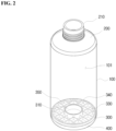
- FIG. 2 is a perspective view showing an inner structure of the cosmetic container according to one embodiment of the present invention
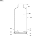
- FIG. 3 is a longitudinal sectional view showing the structure of the cosmetic container according to one embodiment of the present invention
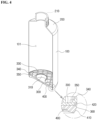
- FIG. 4 is a cutaway perspective view showing the structure of the cosmetic container according to one embodiment of the present invention
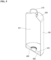
- FIG. 5 is a cutaway perspective view showing a structure of a cosmetic container according to another embodiment of the present invention
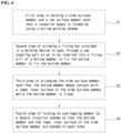
- FIG. 6 is a flowchart for sequentially describing a method of manufacturing a cosmetic container according to one embodiment of the present invention.
- a cosmetic container may include: a side surface member 100 that forms a closed curved surface shielded from an outside so as to form a predetermined reception space 101 for receiving a cosmetic product; a top surface member 200 formed integrally with the side surface member 100 on an upper portion of the side surface member 100, and including a cap coupling part 210 protruding from a center region of the top surface member 200 so as to be coupled with a cap; and a bottom member 300 disposed on a lower portion of the side surface member 100 so as to be fixed to the side surface member 100 so that the reception space 101 is shielded from the outside, wherein the bottom member 300 is drawn inward of the side surface member 100 by a predetermined interval, and an overlapping member 400 that overlaps the bottom member 300 is formed by a double injection scheme to allow the side surface member 100 to surround a bottom surface of the bottom member 300, so that the bottom member 300 and the side surface member 100 are integrally bonded.
- the side surface member 100 refers to a member that forms a side surface of the cosmetic container, in which a plate surface of the side surface member 100 may be curved to form the closed curved surface, and the reception space 101 may be provided inside the side surface member 100 to receive the cosmetic product.
- the top surface member 200 may be formed integrally with the side surface member 100 on the upper portion of the side surface member 100 so that the reception space 101 may be shielded from the outside, and the cap coupling part 210 having a hollow to allow the cosmetic product received in the cosmetic container to be selectively discharged to the outside for use may protrude from the center region of the top surface member 200.
- a screw thread may protrude from an outer surface of the cap coupling part 210 so as to engage with a screw thread formed on an inner surface of a cap (not shown) so that the cap (not shown) may be screw-coupled to the cap coupling part 210.
- the bottom member 300 refers to a member that is disposed on the lower portion of the side surface member 100 so as to be fixed to the side surface member 100 so that the reception space 101 may be shielded from the outside, in which the bottom member 300 may have a peripheral shape corresponding to a shape of a longitudinal section of the side surface member 100.
- a side surface of the bottom member 300 may make close contact with a lower inner surface of the side surface member 100 so that the lower inner surface of the side surface member 100 and the side surface of the bottom member 300 may be easily bonded to each other by the double injection scheme.
- a fixing sill 310 into which a fixing bar for fixing the bottom member 300 when the bottom member 300 and the side surface member 100 are bonded to each other is inserted may protrude from a center region of the bottom member 300.
- the fixing sill 310 may serve to allow the fixing bar to be inserted into the fixing sill 310 so as to fix the bottom member 300, so that the bottom member 300 may be prevented from fluctuating when the bottom member 300 is bonded to a bottom surface of the side surface member 100 by the double injection scheme, and thus the lower inner surface of the side surface member 100 may accurately make contact with the side surface of the bottom member 300.
- a reinforcing rib 330 having a grid shape may protrude by a predetermined height from a top surface of the bottom member 300 except for an inside of the fixing sill 310, so that rigidity of the bottom member 300 may be increased, and thus the bottom member 300 may be prevented from being damaged by an external force.
- an extension part 340 extending by a predetermined height in a height direction of the bottom member 300 may be provided on a periphery of the top surface of the bottom member 300 so that a tapered surface 410 of an overlapping member 400 that will be described below may extend.
- the extension part 340 may serve to firmly bond the bottom member 300 to the side surface member 100 by increasing a contact area between the side surface of the bottom member 300 and the lower inner surface of the side surface member 100.
- a separate reinforcing part 350 having one side surface making contact with an inner surface of the extension part 340 and an opposite side surface making contact with the top surface of the bottom member 300 may be formed on the inner surface of the extension part 340, so that even when an external force is applied, the extension part 340 and the lower inner surface of the side surface member 100 may be maintained in a bonded state, and thus the cosmetic container may be prevented from being damaged.
- a fastening groove 360 having a ring shape may be recessed on a periphery of the bottom surface of the bottom member 300, and a fastening protrusion 420 protruding from a periphery of a top surface of the overlapping member 400 may be inserted into the fastening groove 360, so that a bonding area between the bottom member 300 and the overlapping member 400 may expand, and thus firm coupling may be achieved.
- the overlapping member 400 refers to a member that overlaps the bottom member 300 to allow the side surface member 100 to surround the bottom surface of the bottom member 300 when the side surface member 100 and the bottom member 300 are bonded to each other by the double injection scheme.
- the side surface member 100 and the bottom member 300 may be formed integrally with each other, so that molding of the cosmetic container may be completed.
- the overlapping member 400 may be provided on a side surface thereof with a tapered surface 410, which has a width that is gradually narrowed toward a lower side of the overlapping member 400 and has an outer surface that is curved, and the lower inner surface of the side surface member 100 and the tapered surface 410 may be bonded to each other.
- a cosmetic container may include: a side surface member 100 that forms a closed curved surface shielded from an outside so as to form a predetermined reception space 101 for receiving a cosmetic product; a top surface member 200 formed integrally with the side surface member 100 on an upper portion of the side surface member 100, and including a cap coupling part 210 protruding from a center region of the top surface member 200 so as to be coupled with a cap; and a bottom member 300 disposed on a lower portion of the side surface member 100 so as to be fixed to the side surface member 100 so that the reception space 101 is shielded from the outside, wherein the bottom member 300 is drawn inward of the side surface member 100 by a predetermined interval, an overlapping member 400 that overlaps the bottom member 300 is formed by a double injection scheme to allow the side surface member 100 to surround a bottom surface of the bottom member 300, so that the bottom member 300 and the side surface member 100 are integrally formed, and a separate filling resin
- the filling resin material 370 refers to a member that is applied to the top surface of the bottom member 300 so as to be formed integrally with the bottom member 300, in which the filling resin material 370 may be applied to the top surface of the bottom member 300 so that a grid formed by the reinforcing rib 330 provided in the bottom member 300 may not be exposed to the outside.
- the grid may not be exposed to the outside due to the filling resin material 370 while the rigidity of the bottom member 300 is maintained by the reinforcing rib 330, so that when contents are drawn out to the outside of the cosmetic container for use by using a pump, it is possible to prevent a case in which the contents received in the grid may not be drawn out by the pump so as not to be used as the contents received in the cosmetic container are received in the grid.
- the top surface of the bottom member 300 to which the filling resin material 370 is applied may be inclined downward toward the center region of the bottom member 300, so that the contents may be collected in the center region of the bottom member 300. Accordingly, when the contents are drawn out to the outside by using the pump, a draw-out tube of the pump may be located in the center region of the bottom member 300 to facilitate the drawing-out of the contents, and the contents may be completely used up without allowing the contents to remain.
- a process of manufacturing a cosmetic container according to one embodiment of the present invention which has the configuration described above, will be described as follows.
- a first step S1 of molding a side surface member 100 and a top surface member 200 such that a reception space 101 is formed by using a hollow molding scheme may be performed.
- a second step S2 of allowing a fixing bar provided in a molding device to pass through a cap coupling part 210 formed on the top surface member 200 so as to be inserted into a fixing sill 310 of a bottom member 300 to fix the bottom member 300 may be performed.
- a third step S2 of arranging the side surface member 100 such that the bottom member 300 makes contact with a lower inner surface of the side surface member 100 while the bottom member 300 is fixed may be performed.
- a fourth step S4 of forming an overlapping member 400 to surround a bottom surface of the bottom member 300 to overlap the bottom member 300 when double injection is performed while the lower inner surface of the side surface member 100 makes contact with a side surface of the bottom member 300 so that the side surface of the bottom member 300 and the lower inner surface of the side surface member 100 are bonded to each other may be performed.
- the fixing bar may be separated from the fixing sill 310, and the cosmetic container, which has been molded, may be removed from the molding device, so that the manufacture of the cosmetic container may be completed.
- a bottom surface of the cosmetic container for storing a cosmetic product is formed firmly and integrally with a side surface of the cosmetic container, and rigidity of the bottom surface is improved so that the bottom surface is prevented from being damaged even when the cosmetic container is accidentally dropped, and thus the cosmetic product may be permanently received in the cosmetic container, which improves user satisfaction.
Landscapes
- Engineering & Computer Science (AREA)
- Mechanical Engineering (AREA)
- Ceramic Engineering (AREA)
- Containers Having Bodies Formed In One Piece (AREA)
- Manufacturing & Machinery (AREA)
- Injection Moulding Of Plastics Or The Like (AREA)
Applications Claiming Priority (1)
| Application Number | Priority Date | Filing Date | Title |
|---|---|---|---|
| KR1020210184663A KR102409223B1 (ko) | 2021-12-22 | 2021-12-22 | 화장품 용기 및 그 제조방법 |
Publications (3)
| Publication Number | Publication Date |
|---|---|
| EP4201830A1 true EP4201830A1 (de) | 2023-06-28 |
| EP4201830C0 EP4201830C0 (de) | 2025-01-22 |
| EP4201830B1 EP4201830B1 (de) | 2025-01-22 |
Family
ID=82217445
Family Applications (1)
| Application Number | Title | Priority Date | Filing Date |
|---|---|---|---|
| EP22182787.6A Active EP4201830B1 (de) | 2021-12-22 | 2022-07-04 | Kosmetikbehälter und herstellungsverfahren dafür |
Country Status (4)
| Country | Link |
|---|---|
| US (1) | US12084222B2 (de) |
| EP (1) | EP4201830B1 (de) |
| JP (1) | JP7513660B2 (de) |
| KR (1) | KR102409223B1 (de) |
Families Citing this family (1)
| Publication number | Priority date | Publication date | Assignee | Title |
|---|---|---|---|---|
| USD1036259S1 (en) * | 2019-04-09 | 2024-07-23 | Vetroelite Spa | Bottle |
Citations (4)
| Publication number | Priority date | Publication date | Assignee | Title |
|---|---|---|---|---|
| KR200384766Y1 (ko) * | 2005-03-08 | 2005-05-17 | 주식회사 태평양 | 이종내용물을 혼합하여 사용하는 화장품용기 |
| KR20150001417U (ko) * | 2013-10-02 | 2015-04-13 | (주)아모레퍼시픽 | 제2내용물보관부가 형성된 화장품 용기 |
| KR20190117061A (ko) * | 2018-04-06 | 2019-10-16 | 주식회사 삼화플라스틱 | 에어리스 펌핑형 화장품 용기 |
| KR102318862B1 (ko) * | 2020-04-20 | 2021-10-28 | 정만택 | 에어리스 펌핑형 화장품 용기 |
Family Cites Families (16)
| Publication number | Priority date | Publication date | Assignee | Title |
|---|---|---|---|---|
| KR200387285Y1 (ko) | 2005-04-02 | 2005-06-17 | 주식회사 태평양 | 고압가스로 피스톤을 밀어주는 화장품 용기 |
| KR20090065146A (ko) | 2007-12-17 | 2009-06-22 | 주식회사 생 코레 인터내셔날 | 액상 화장품 용기 |
| JP2014046979A (ja) | 2012-09-03 | 2014-03-17 | Nakayama Kogyo Kk | バリア容器およびバリア容器の製造方法 |
| JP6433112B2 (ja) | 2013-03-01 | 2018-12-05 | 大日本印刷株式会社 | 電子レンジ用紙カップ |
| KR101448957B1 (ko) | 2013-08-09 | 2014-10-13 | 쓰리애플즈코스메틱스 주식회사 | 화장품 용기 |
| KR20160033400A (ko) | 2014-09-18 | 2016-03-28 | (주)스톡미 | 식품 저장 및 보존용 밀폐 용기(100) |
| KR101520448B1 (ko) | 2014-11-27 | 2015-05-14 | 서성은 | 용기의 인서트 사출방법 |
| KR20160124487A (ko) * | 2015-04-20 | 2016-10-28 | 김재일 | 일회용 조리 용기 |
| JP6737590B2 (ja) * | 2015-12-09 | 2020-08-12 | 株式会社平和化学工業所 | 二重容器及びその製造方法 |
| IT201700029991A1 (it) | 2017-03-17 | 2018-09-17 | Caffitaly System Spa | Capsula per la preparazione di una bevanda |
| US11641923B2 (en) * | 2018-11-07 | 2023-05-09 | HCT Group Holdings Limited | Cosmetic container with a capped seal |
| KR102042978B1 (ko) | 2019-05-16 | 2019-11-11 | 이기수 | 사출식 비융착 결합구조의 안전 앰플 용기 |
| KR20200144304A (ko) | 2019-06-18 | 2020-12-29 | (주) 이니스프리 | 화장품 용기 및 이의 제조 방법 |
| KR20210005426A (ko) * | 2019-07-05 | 2021-01-14 | 펌텍코리아 (주) | 편리한 리필 구조를 갖는 화장품 용기 |
| US20210387777A1 (en) * | 2020-06-10 | 2021-12-16 | HCT Group Holdings Limited | Cosmetic bottle |
| KR102334654B1 (ko) * | 2021-09-29 | 2021-12-02 | 김경숙 | 자동 충전 스포이트형 화장품 용기 |
-
2021
- 2021-12-22 KR KR1020210184663A patent/KR102409223B1/ko active Active
-
2022
- 2022-06-27 US US17/850,461 patent/US12084222B2/en active Active
- 2022-07-04 JP JP2022107656A patent/JP7513660B2/ja active Active
- 2022-07-04 EP EP22182787.6A patent/EP4201830B1/de active Active
Patent Citations (4)
| Publication number | Priority date | Publication date | Assignee | Title |
|---|---|---|---|---|
| KR200384766Y1 (ko) * | 2005-03-08 | 2005-05-17 | 주식회사 태평양 | 이종내용물을 혼합하여 사용하는 화장품용기 |
| KR20150001417U (ko) * | 2013-10-02 | 2015-04-13 | (주)아모레퍼시픽 | 제2내용물보관부가 형성된 화장품 용기 |
| KR20190117061A (ko) * | 2018-04-06 | 2019-10-16 | 주식회사 삼화플라스틱 | 에어리스 펌핑형 화장품 용기 |
| KR102318862B1 (ko) * | 2020-04-20 | 2021-10-28 | 정만택 | 에어리스 펌핑형 화장품 용기 |
Also Published As
| Publication number | Publication date |
|---|---|
| JP7513660B2 (ja) | 2024-07-09 |
| JP2023093298A (ja) | 2023-07-04 |
| EP4201830C0 (de) | 2025-01-22 |
| US12084222B2 (en) | 2024-09-10 |
| EP4201830B1 (de) | 2025-01-22 |
| US20230192345A1 (en) | 2023-06-22 |
| KR102409223B1 (ko) | 2022-06-16 |
Similar Documents
| Publication | Publication Date | Title |
|---|---|---|
| US9924776B2 (en) | Container for a cosmetic product | |
| EP4201830A1 (de) | Kosmetikbehälter und herstellungsverfahren dafür | |
| EP0300786A2 (de) | Kombination von Sauger und Kappe aus einem Stück und Verfahren zu ihrer Herstellung | |
| US20240116680A1 (en) | Container closure | |
| US12127661B2 (en) | Cosmetic product dispenser pot with a stacked base, refill and cover | |
| CN105667925A (zh) | 瓶 | |
| KR20220050154A (ko) | 일체형 화장품 드로퍼 | |
| KR102450039B1 (ko) | 리필구조의 스틱형 화장품 용기 | |
| EP3542771B1 (de) | Behälter und herstellungsverfahren für den behälter | |
| JP6541336B2 (ja) | 少量化容器の製造方法 | |
| JP7027397B2 (ja) | プラスチック射出成形により製造された卵パック | |
| CN216165795U (zh) | 一种替换装膏霜瓶 | |
| KR102409222B1 (ko) | 화장품 용기 및 그 제조방법 | |
| KR102219284B1 (ko) | 리필 가능한 내용기 구조를 갖는 용기의 제조방법 | |
| US11780655B2 (en) | Structure for one-touch opening/closing of cap and container | |
| KR100453143B1 (ko) | 다용도 케이스 | |
| KR20110008511U (ko) | 종량제봉투가 내장되는 압착식 쓰레기통 | |
| CN209436525U (zh) | 一种多腔膏霜瓶 | |
| KR102944539B1 (ko) | 스틱형 용기 | |
| JPH038189Y2 (de) | ||
| KR102828108B1 (ko) | 길이 조절이 가능한 일회용 젖병 | |
| KR102050048B1 (ko) | 이중 튜브 뚜껑 | |
| CN213155254U (zh) | 一种可压缩勺以及带可压缩勺的盖 | |
| CN206462763U (zh) | 一种杯盖及杯子 | |
| CN219983449U (zh) | 一种容积可调节的杯子 |
Legal Events
| Date | Code | Title | Description |
|---|---|---|---|
| PUAI | Public reference made under article 153(3) epc to a published international application that has entered the european phase |
Free format text: ORIGINAL CODE: 0009012 |
|
| STAA | Information on the status of an ep patent application or granted ep patent |
Free format text: STATUS: REQUEST FOR EXAMINATION WAS MADE |
|
| 17P | Request for examination filed |
Effective date: 20220704 |
|
| AK | Designated contracting states |
Kind code of ref document: A1 Designated state(s): AL AT BE BG CH CY CZ DE DK EE ES FI FR GB GR HR HU IE IS IT LI LT LU LV MC MK MT NL NO PL PT RO RS SE SI SK SM TR |
|
| GRAP | Despatch of communication of intention to grant a patent |
Free format text: ORIGINAL CODE: EPIDOSNIGR1 |
|
| STAA | Information on the status of an ep patent application or granted ep patent |
Free format text: STATUS: GRANT OF PATENT IS INTENDED |
|
| RIC1 | Information provided on ipc code assigned before grant |
Ipc: B65D 1/02 20060101AFI20240814BHEP |
|
| INTG | Intention to grant announced |
Effective date: 20240909 |
|
| GRAS | Grant fee paid |
Free format text: ORIGINAL CODE: EPIDOSNIGR3 |
|
| GRAA | (expected) grant |
Free format text: ORIGINAL CODE: 0009210 |
|
| STAA | Information on the status of an ep patent application or granted ep patent |
Free format text: STATUS: THE PATENT HAS BEEN GRANTED |
|
| AK | Designated contracting states |
Kind code of ref document: B1 Designated state(s): AL AT BE BG CH CY CZ DE DK EE ES FI FR GB GR HR HU IE IS IT LI LT LU LV MC MK MT NL NO PL PT RO RS SE SI SK SM TR |
|
| REG | Reference to a national code |
Ref country code: GB Ref legal event code: FG4D |
|
| REG | Reference to a national code |
Ref country code: CH Ref legal event code: EP |
|
| REG | Reference to a national code |
Ref country code: IE Ref legal event code: FG4D |
|
| REG | Reference to a national code |
Ref country code: DE Ref legal event code: R096 Ref document number: 602022009735 Country of ref document: DE |
|
| U01 | Request for unitary effect filed |
Effective date: 20250210 |
|
| U07 | Unitary effect registered |
Designated state(s): AT BE BG DE DK EE FI FR IT LT LU LV MT NL PT RO SE SI Effective date: 20250214 |
|
| PG25 | Lapsed in a contracting state [announced via postgrant information from national office to epo] |
Ref country code: RS Free format text: LAPSE BECAUSE OF FAILURE TO SUBMIT A TRANSLATION OF THE DESCRIPTION OR TO PAY THE FEE WITHIN THE PRESCRIBED TIME-LIMIT Effective date: 20250422 |
|
| PG25 | Lapsed in a contracting state [announced via postgrant information from national office to epo] |
Ref country code: PL Free format text: LAPSE BECAUSE OF FAILURE TO SUBMIT A TRANSLATION OF THE DESCRIPTION OR TO PAY THE FEE WITHIN THE PRESCRIBED TIME-LIMIT Effective date: 20250122 |
|
| PG25 | Lapsed in a contracting state [announced via postgrant information from national office to epo] |
Ref country code: ES Free format text: LAPSE BECAUSE OF FAILURE TO SUBMIT A TRANSLATION OF THE DESCRIPTION OR TO PAY THE FEE WITHIN THE PRESCRIBED TIME-LIMIT Effective date: 20250122 |
|
| PG25 | Lapsed in a contracting state [announced via postgrant information from national office to epo] |
Ref country code: NO Free format text: LAPSE BECAUSE OF FAILURE TO SUBMIT A TRANSLATION OF THE DESCRIPTION OR TO PAY THE FEE WITHIN THE PRESCRIBED TIME-LIMIT Effective date: 20250422 Ref country code: IS Free format text: LAPSE BECAUSE OF FAILURE TO SUBMIT A TRANSLATION OF THE DESCRIPTION OR TO PAY THE FEE WITHIN THE PRESCRIBED TIME-LIMIT Effective date: 20250522 |
|
| PG25 | Lapsed in a contracting state [announced via postgrant information from national office to epo] |
Ref country code: HR Free format text: LAPSE BECAUSE OF FAILURE TO SUBMIT A TRANSLATION OF THE DESCRIPTION OR TO PAY THE FEE WITHIN THE PRESCRIBED TIME-LIMIT Effective date: 20250122 |
|
| PG25 | Lapsed in a contracting state [announced via postgrant information from national office to epo] |
Ref country code: GR Free format text: LAPSE BECAUSE OF FAILURE TO SUBMIT A TRANSLATION OF THE DESCRIPTION OR TO PAY THE FEE WITHIN THE PRESCRIBED TIME-LIMIT Effective date: 20250423 |
|
| U20 | Renewal fee for the european patent with unitary effect paid |
Year of fee payment: 4 Effective date: 20250729 |
|
| PG25 | Lapsed in a contracting state [announced via postgrant information from national office to epo] |
Ref country code: SM Free format text: LAPSE BECAUSE OF FAILURE TO SUBMIT A TRANSLATION OF THE DESCRIPTION OR TO PAY THE FEE WITHIN THE PRESCRIBED TIME-LIMIT Effective date: 20250122 |
|
| PG25 | Lapsed in a contracting state [announced via postgrant information from national office to epo] |
Ref country code: CZ Free format text: LAPSE BECAUSE OF FAILURE TO SUBMIT A TRANSLATION OF THE DESCRIPTION OR TO PAY THE FEE WITHIN THE PRESCRIBED TIME-LIMIT Effective date: 20250122 |
|
| PG25 | Lapsed in a contracting state [announced via postgrant information from national office to epo] |
Ref country code: SK Free format text: LAPSE BECAUSE OF FAILURE TO SUBMIT A TRANSLATION OF THE DESCRIPTION OR TO PAY THE FEE WITHIN THE PRESCRIBED TIME-LIMIT Effective date: 20250122 |
|
| PLBE | No opposition filed within time limit |
Free format text: ORIGINAL CODE: 0009261 |
|
| STAA | Information on the status of an ep patent application or granted ep patent |
Free format text: STATUS: NO OPPOSITION FILED WITHIN TIME LIMIT |
|
| REG | Reference to a national code |
Ref country code: CH Ref legal event code: L10 Free format text: ST27 STATUS EVENT CODE: U-0-0-L10-L00 (AS PROVIDED BY THE NATIONAL OFFICE) Effective date: 20251203 |
|
| 26N | No opposition filed |
Effective date: 20251023 |
|
| REG | Reference to a national code |
Ref country code: CH Ref legal event code: H13 Free format text: ST27 STATUS EVENT CODE: U-0-0-H10-H13 (AS PROVIDED BY THE NATIONAL OFFICE) Effective date: 20260224 |